

Page 1

User Guide
110259-005
RL3/3e & RL4/4e
Page 2

Page 3

Copyright Information
The Bluetooth word mark and logos are registered trademarks owned by Bluetooth SIG, Inc., and
any use of such marks by Datamax-O’Neil is under license.
This manual and any examples contained herein are provided “as is” and are subject to change without
notice. Datamax-O’Neil makes no warranty of any kind with regard to this manual, including, but not
limited to, the implied warranties of merchantability and fitness for a particular purpose. Datamax-O’Neil
shall not be liable for any errors or for incidental or consequential damages in connection with the
furnishing, performance or use of this manual, or the examples herein. This guide is copyri ghted. All rights
are reserved. This guide may not, in whole or in part, be reproduced, translated, stored in a retrieval
system or transmitted in any form, or by any means, electronic, mechanical, photographic or otherwise,
without the prior written consent of Datamax-O’Neil.
Windows
Corporation. Wavelink
All other brand and product names are trademarks, service marks, registered trademarks or registered
service marks of their respective companies.
7, Windows® 8, Windows® Mobile and Windows® CE are registered trademark of the Microsoft
®
Avalanche™ is a registered trademark of Wavelink Corporation.
Limitation of Liability
In no event shall Datamax-O’Neil be liable to the purchaser for any indirect, special or consequential
damages or lost profits arising out of or relating to Datamax-O’Neil’s products, or the performance or a
breach thereof, even if Datamax-O’Neil has been advised of the possibility thereof. Datamax-O’Neil’s liability,
if any, to the purchaser or to the customer of the purchaser hereunder shall in no event exceed the total
amounts paid to Datamax-O’Neil hereunder by the purchaser for a defective product.
In no event shall Datamax-O’Neil be liable to the purchaser for any damages resulting from or related to
any failure or delay of Datamax-O’Neil in the delivery or installation of the computer hardware, suppl ies or
software, or in the performance of any services.
Some states do not permit the exclusion of incidental or consequential damages, and in those states the
foregoing limitations may not apply. The warranties here give you specific legal rights, and you may have
other legal rights, which vary from state to state.
Firmware (Software) Agreement
The enclosed Firmware (Software) resident in the Printer is owned by Licensor or its suppliers and is
licensed for used only on a single printer in the user’s Trade or Business. The User agrees not to, and not
to authorize or permit any other person or party to, duplicate or copy the Firmware or the information
contained in the non-volatile or programmable memory. The firmware (Software) is protected by
applicable copyright laws and Licensor retains all rights not expressly granted. In no event will Licensor or
its suppliers be liable for any damages or loss, including direct, incidental, economic, special or
consequential damages, arising out of the use or inability to use the Firmware (Software).
Information in this document is subject to change without notice and does not represent a commitment on
the part of Datamax-O’Neil Corporation. No part of this manual may be reproduced or transmitted in any
form or by any means, and for any purpose other than the purchaser's personal use, without the
expressed written permission of Datamax-O’Neil Corporation.
All rights reserved.
Copyright ©2015-2018, Datamax-O’Neil Corporation
Part Number: 110259-005
Page 4

Important Safety Instructions
This printer has been carefully designed to provide many years of safe, reliable performance. As with all
types of electrical equipment, however, there are a few basic precautions you should take to avoid hurting
yourself or damaging the equipment:
• Carefully read the provided installation and operating instructions
• Read and follow all warning instruction labels on the printer
• Place the printer on a flat, firm, solid surface
• Make sure all openings on the printer remain unblocked; never insert anything into the openings or
ventilation slots
• Do not place the printer near a heat source
• Do not use your printer near water or spill liquid into it
• Be certain that your power source matches a listed voltage rating for the printer (if unsure, check with
your dealer or local utility company)
• Do not place the power cord where it can be stepped on and, if the power cord becomes damaged,
immediately replace it
• If service is required, use only qualified trained technicians to repair your printer
Page 5

The manufacturer declares under sole responsibility that this product conforms to the following
C-tick, A-tick
Agency Compliance and Approvals
UL60950-1; 2nd Edition
CSA C22.2 No. 60950-1-07 2nd Edition
standards or other normative documents:
Applicable Directive
2004/108/EC, 73/23/EEC
Applicable Standards
RL3 Printers: EN55022 Class A; RL4 Printers: EN55022 Class B
EN55024 (1998), A1 (2001), A2 (2003)
IEC60950-1 (2005) 2nd Edition
RLe Printers: FCC 15 Class B, EN55022 Class B
EN55024
IEC 60950-1 2nd edition
EAC – Customs Union
CCC, SRC
The RL3e and RL4e printers with the 802.11 a/b/g/n and Bluetooth wireless technology options has been found
compliant to the SAR requirements. The maximum SAR measured value was 0.572 W/kg averaged over 1 gram.
FCC Notice:
This equipment has been tested and found to comply with the limits for a Class B digital device, pursuant to Part 15
of the FCC Rules. These limits are designed to provide reasonable protection against harmful interference in a
residential installation.
This equipment generates, uses and can radiate radio frequency energy and, if not installed and used in accordance
with the instructions, it may cause harmful interference to radio communications. However, there is no guarantee
that interference will not occur in a particular installation. If this equipment does cause harmful interference to radio
or television reception, which can be determined by turning the equipment off and on, the user is encouraged to try
to correct the interference by one or more of the following measures:
Reorient or relocate the receiving antenna
Increase the separation between the equipment and receiver
Connect the equipment to an outlet on a circuit different from that to which the receiver is connected
Consult the dealer or an experienced radio/TV technician for help
Page 6

1 Getting Started
1.1 Introduction ............................................................................................................ 1
1.2 Unpacking ............................................................................................................... 1
1.3 Carry Accessories ..................................................................................................... 2
2 Printer Setup
2.1 Charging Your Battery ............................................................................................... 4
2.2 Interface Connections ............................................................................................... 6
2.3 Loading Media (Labels or Paper) ................................................................................. 7
2.3.1 Loading for Presenter Mode ............................................................................. 9
2.3.2 External Media Loading ................................................................................. 10
2.3
Real-Time Clock (RTC) ............................................................................................ 12
3 Printer Operation
3.1 Front Panel ............................................................................................................ 13
3.1.1 LCD Icons ................................................................................................... 13
3.1.2 Audible Alerts .............................................................................................. 13
3.1.3 Buttons....................................................................................................... 14
3.1.4 Menu .......................................................................................................... 14
3.2 Configuration Label ................................................................................................. 15
3.3
Establishing Printer Connec ti on ................................................................................ 15
3.4
NETira
3.5 Media and Calibration ............................................................................................. 19
3.6 Presenter Mode ...................................................................................................... 26
3.7 Printer Input Mode (Emulation) ................................................................................ 28
™
CT Printer Configuration Utility ..................................................................... 17
3.5.1 Selecting Media Type .................................................................................... 19
3.5.2 Quick Media Calibration ................................................................................. 21
3.5.3 Manual Media Calibration ............................................................................... 22
3.8 Saving & Loading Configuration Files ......................................................................... 29
3.9 Printer Demo ......................................................................................................... 30
3.10 Firmware Update .................................................................................................... 31
www.datamax-oneil.com i
Page 7

4 Maintenance and Adjustments
4.1 Cleaning Intervals .................................................................................................. 32
4.2 Cleaning the Printhead ............................................................................................ 33
5 Troubleshooting
5.1 Introduction .......................................................................................................... 35
5.2 Troubleshooting Tips ............................................................................................... 35
Appendix A: Specifications .................................................................................. A-1
Appendix B: Media and Supplies
B.1 Supplies ...................................................................................................................................... B-1
B.2 Peripherals and Ac c essories .................................................................................... B-3
Appendix C: Wireless LAN and Bluetooth® Setup
C.1 Introduction ......................................................................................................... C-1
C.2 Static IP/DHCP Setting ........................................................................................... C-2
C.3 Infrastructure/Ad-hoc Setting ................................................................................. C-3
C.4 Wireless LAN Security Settings ................................................................................ C-4
C.4.1 WEP 64 & 128 Bit ........................................................................................ C-4
C.4.2 WPA2-PSK w/CCMP ..................................................................................... C-5
C.4.3 WPA2-PSK w/TKIP ....................................................................................... C-5
C.4.4 WPA2-Enterprise ......................................................................................... C-6
C.4.5 WPA-PSK TKIP w/TKIP ................................................................................. C-7
C.5 Resetting the Printer .............................................................................................. C-8
C.6 Bluetooth® Setup .................................................................................................. C-8
Appendix D: USB Setup
D.1 Introduction ......................................................................................................... D-1
D.2 Printer Configuration .............................................................................................. D-2
D.3 Composite Class Installation ................................................................................... D-3
D.4 CDC Class (optional) .............................................................................................. D-7
D.5 Printer Class (optional)........................................................................................... D-8
Appendix E: Error Codes
E.1 Conditions ............................................................................................................ E-1
E.2 Warnings ............................................................................................................. E-2
E.3 Faults .................................................................................................................. E-3
Appendix F: Reflective Media-Calibration Label…………………………………………….F-1
www.datamax-oneil.com ii
Page 8
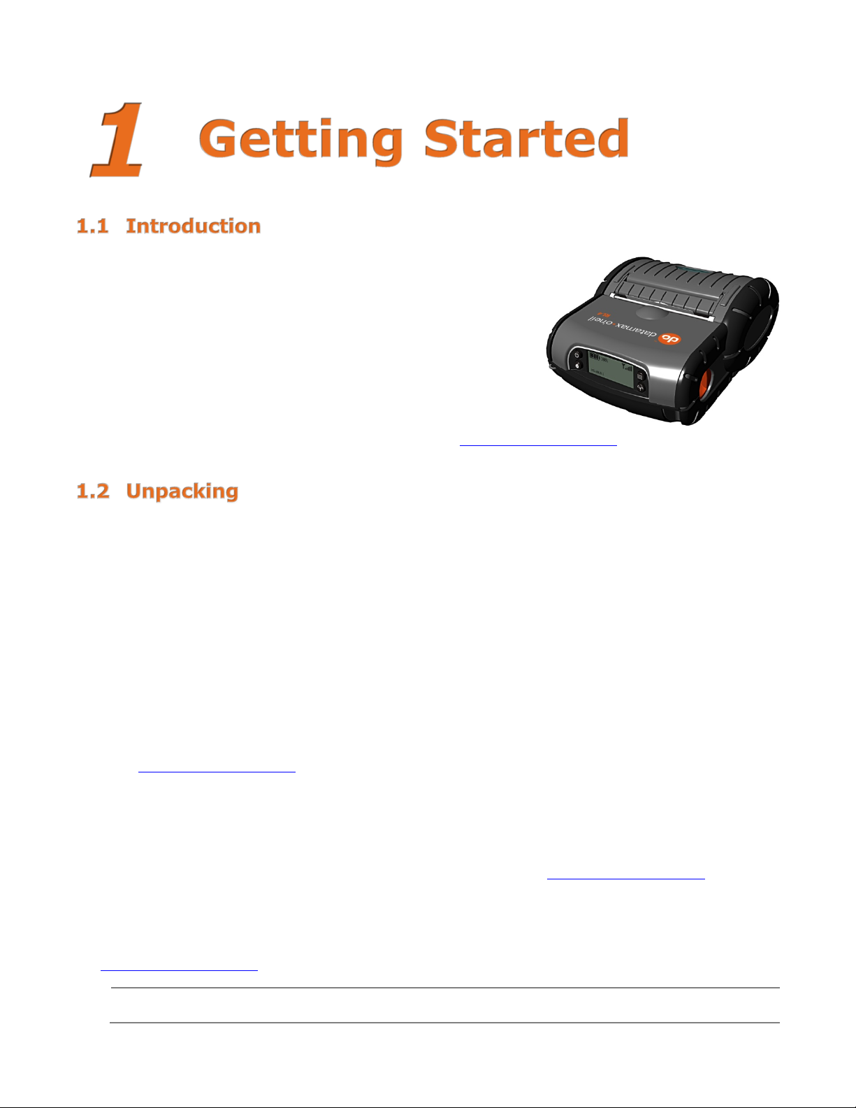
Congratulations on your RL3e/RL4e printer purchase. The RL Series
printer family, hereafter referred to as “the printer,” blends the
rugged durability with state-of-the-art electronics and user-friendly
features to redefine the standard in portable thermal printers. The
printer’s RS-232 serial, USB, or optional wireless LAN or Bluetooth
wireless technology allows easy interfacing to any host system.
This manual provides all the information necessary to operate the
printer.
To print labels or receipts, simply refer to the instructions included
with the software you have chosen to use to create the labels.
A Windows
custom program, a copy of the Programmer’s Manual can also be found on our website.
®
printer driver can be found on our website (www.datamax-oneil.com). If you wish to write a
®
After removing the printer from the packaging material, check the contents. The following items should be
included:
Printer
Belt Clip
Documentation
Additional Requirements:
In order to print from your RL Series printer, the following items are required. If you do not have these
items, contact your customer-support or sales representative for advice on where to purchase them or
download the required software items.
Power Supply (sold separately) – The appropriate power supply for your region is required and is
not included as part of the printer purchase. If you do not have an applicable power supply for your
printer, you will need to order one before getting started.
NETira
www.datamax-oneil.com
Connection Cable – If the printer you are setting up does not have a Bluetooth® wireless
connection feature, or if you are seeking to connect your printer over a wired connection, you will
need a cable. Available options: Serial Cable – Coiled
(Part No. 210191-101); or USB (Part No. 210304-100).
Print Media – Datamax-O’Neil offers a full line of applicable printing labels, receipt media and
supplies. It is recommended that Datamax-O’Neil-approved media be used to ensure the quality of
your printing and maintain the integrity of your warranty. Go to www.datamax-oneil.com
details on available supplies.
NOTE: This manual contains instructions and information regarding RL Series printers with vari ou s
options. Not all features listed in this guide may be applicable to your RL Series printer model. If you are
unsure of whether your printer contains these features, contact Datamax-O’Neil or visit our website at
www.datamax-oneil.com
™
CT Configuration Software, version 1.0.0 or greater. A v ailable for download at
(Part No. 210191-101); Serial Cable – Straight
for more
for further details.
It is a good idea to save all packaging materials in the event that shipping the printer is ever
required.
www.datamax-oneil.com 1
Page 9

Belt Clip
Belt Clip
Shoulder Strap/Hand Strap
shown.
Attachment Points
Several accessories are available for the printer to allow for ease of use and portability.
Included with printer, the Belt Clip allows easy attachment
to a belt or similar object.
(Optional Items)
Choose either a hand or longer shoulder strap for
maximum comfort and flexibility. Each strap
incorporates heavy-duty clasps for an easy and secure
attachment; however, these are not OSHA-approved
safety straps.
Both the hand strap and shoulder strap have a limited
breakaway strength. If the strap is caught or wrapped
and pulled beyond normal use the strap will come off
the Attachment Points. Do not use the straps for
mounting, hanging or as the means for a permanent
installation of the printer. If the latch appears damaged
(white stress marks in plastic) discontinue use and
replace.
Orient and connect the clip(s) to the Attachment Points
Belt Loop (Optional Available Accessory)
The Velcro® loop fastens comfortably and securely
around the belt and keeps the printer secure, yet swivels
for comfort when the user is bending over or getting in
and out of vehicles.
www.datamax-oneil.com 2
Page 10

Proper use of this case will allow the printer to be used in
used.
Never attempt to charge when the printer case or printer is wet as a short circuit could occur.
before installing the battery or charging.
IP54 Soft Case (Optional Available Accessory)
harsh, dusty or rainy environments. This case is certified to
an IP54 rating, so when properly used, it will protect your
product against particles as small as dust, and water from
any direction. This case can be used in conjunction with the
hand/shoulder straps, as well the belt-loop and belt-clip
accessories.
The IP54 case has been tested at an accredited lab for use in
dusty and heavy water environments. However, it is not
designed for extensive prolonged use in the rain. During
normal operation, water could enter into the case during
media changing. This ingress of moisture should be avoided at
all costs. The printer warranty cannot be honored for
excessive water inside the printer even if an IP54 case is
1. Open the case at the two (2) side zippers.
2. Slide the printer into the case.
3. Close the case using the two (2) side zippers and Velcro
4. Fold back the paper exit flap for each print job. The paper exit flap can also be rolled up out of the
way and secured using the Velcro® strip; doing so decreases the effectiveness of the case for water
protection.
®
closure.
Remove the printer from the case, allow to completely dry and then charge. In the event water is
believed to have entered the printer, remove the battery and allow the unit to dry for several days
www.datamax-oneil.com 3
Page 11

The maximum operating temperature of the printer is 50°C (122ºF). However, the maximum
Battery Isolator
Battery
Your printer utilizes an external auto-ranging power supply to char ge its battery. Before using your
printer, the battery should be fully charged. The printer cannot be operated through AC power alone and
requires the battery to be installed. Ensure that the operating ranges of the power supply are compatible
with your electrical service (see Appendix A) then follow these instructions:
operating temperature for charging when used with a Datamax-O’Neil power supply is limited to
40°C (104ºF). Please charge the printer in a suitable location that meets this temperature
requirement.
There is a risk of explosion if the battery is replaced by an incorrect type. Dispose of used
batteries properly.
1) Remove the Battery from the printer. Then remove the red Battery Isolator.
312
2) Re-install the Battery into the printer. Align the release tab with the same side as the charge
contacts and lock the battery into position. The latch should click into place when seated properly.
312
www.datamax-oneil.com 4
Page 12

Power Supply
Electrical Outlet
Power Jack
External Charging Contacts
3) Connect the Power Supply to Power Jack of the printer.
4) Connect the AC Power Cord to the Power Supply.
5) Connect the AC Power Cord to an Electrical Outlet.
Battery must be sufficiently charged before operating the printer while connected to an AC power
supply.
312
AC Power Cord
Battery Guidelines:
• DO NOT store batteries in cold or hot conditions
• DO NOT drop the battery pack. In the event of a drop carefully inspect the battery plastic and contacts for damage. If you
suspect damage, do not use the battery.
• DO NOT use sharp tools to remove the pack. If a pack is punctured or cracked, immediately remove from the printer.
• If the pack becomes extremely hot, or begins to smell, DO NOT touch. Place immediately in an empty metal trash can.
• DO NOT use the battery for any product other than the RL3e/RL4e or designated printer
• DO NOT tamper with or attempt to disassemble the battery pack
• DO NOT subject the battery pack to water or liquids of any kind
• Be careful when setting the battery pack down on a flat surface; always store the battery pack with the contacts facing up
• DO NOT stack batteries with the contacts facing each other
• Replacement batteries come in individual boxes, store this way
• Batteries have a shelf life of one (1) year
The printer is also designed with externalcharging capabilities (optional) using DatamaxO’Neil-approved charging accessories. For more
information on available optional charging
accessories, or a guide to using the multi-bay
charging accessory, go to
oneil.com and select the RL or RLe printer for a
list of available chargers, or the Install Guide for
information on its use.
www.datamax-oneil.com 5
www.datamax-
Page 13

Serial (RJ11)
USB
Charging Port
Before connecting Power or interface cables to the printer, be sure the printer is powered off. For
setting up the printer using Netira™ CT.
Connecting your printer to a host device can be set up using various connection options that are available
for your printer. If your RL model has the available feature, you can connect via Serial, USB, Wireless
802.11 LAN or Wireless via Bluetooth
that provides valid data. If you wish to change that connection once established, you will need to power
the printer off and back on again. Choose from the options below for instructions on using the various
options for establishing a connection to your host device. Once established, you can proceed to Section
3.3 for information on using the configuration software (NETira
serial options require the appropriate cables for use. See Section 1.3 for a list of available cables.
®
. The printer will automatically connect to the first available port
™
CT). Wired connections using USB or
hardware setup instructions, see Section 3.3 – Establishing Printer Connection. Once hardware
connection has been established, go to the corresponding Appendix listed below for instructions on
Serial Connection
The serial interface supports RS-232 communications via an RJ-11 connector. The following list of serialport settings is menu-selectable (via host software/driver) and must match the host computer’s serial-port
settings:
> Baud Rate (Default 9600 bps)
> Parity = (Default N)
> Word Length = (Default 8 bits)
> Stop Bits = (Default 1)
USB Connection (USB)
The USB Interface is supported in Windows
your host computer, installation may differ slightly. For setup information, see Appendix D
®
98 and greater. Depending upon the operating system of
.
Optional Wireless LAN and Bluetooth
For setup information on optional Wireless LAN and Bluetooth
®
®
connections, see Appendix C.
www.datamax-oneil.com 6
Page 14

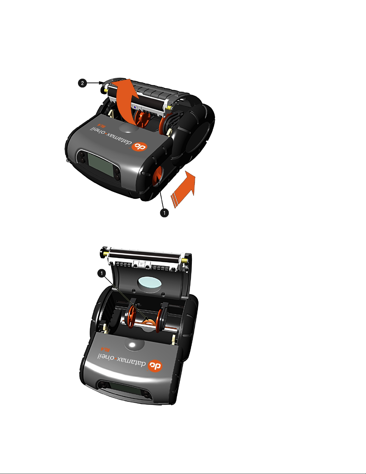
Thumb Latch
Cover
Supply Hubs
Load media into the printer as follows:
1) Slide the Thumb Latch rearward and then lift up on the printer’s Cover.
2) Slide and hold open the Supply Hubs.
www.datamax-oneil.com 7
Page 15
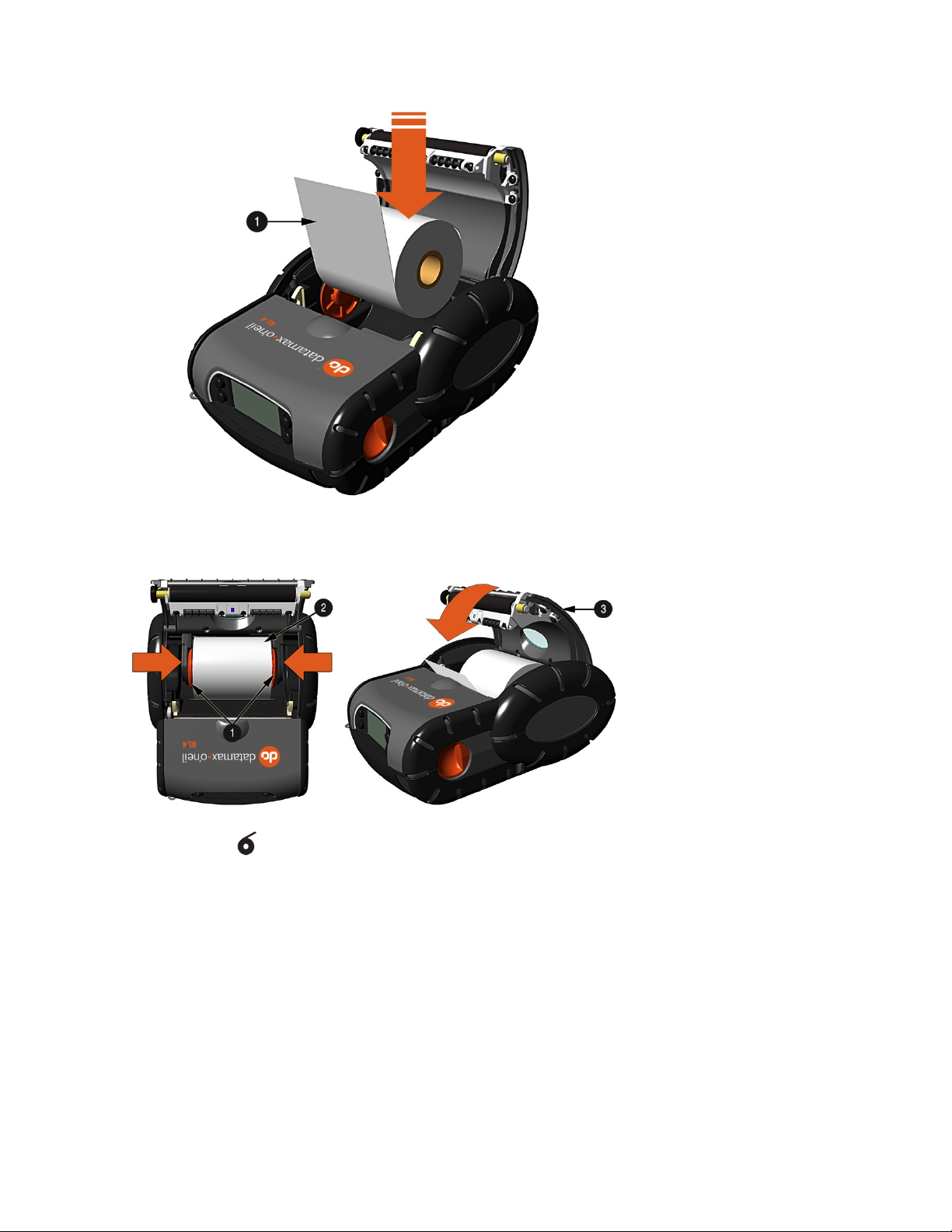
Roll of Media
Supply Hubs
Roll of Media
Cover
3) Orient the Roll of Media (paper or labels) as shown and insert it into the printer.
4) Allow the Supply Hubs to retract onto the Roll of Media. Then close the printer’s Cover and press
downward until latched.
5) Press the button two or three times to normalize tracking. The printer should advance the
media to the start of the next label for each press.
www.datamax-oneil.com 8
Page 16

Media Backing
Peeler Door
With some types of media, it may be necessary to periodically remove slack in the backing (liner)
on the backing material until the slack is removed and is tight.
2.3.1 Loading for Presenter Mode
The printer must be configured for use in “Presenter Mode.” See Section 3.6 for connecting and
configuring the printer’s settings.
1) Load media as described in Section 2.3 (steps 1-3).
2) Remove about eight (8) inches (203 mm) of labels from the Media Backing.
3) Open the Peeler D o o r. Route the media as shown below.
312
4) Pull the media backing tight and then close the Peeler Do or .
5) Press the button two or three times to normalize tracking. The printer should advance the media to
the start of the next label for each press.
material that accumulates before the Peeler Door. To remove: Hold the Peeler Door closed and pull
When using the printer in presenter mode a large amount of backing can accumulate. Be sure to
contain the backing as it can become a tripping hazard. When removing backing material from the
printer do not pull the backing as it may disturb the printer. Cut using scissors or tear using two
hands a few feet from the printer.
www.datamax-oneil.com 9
Page 17
Thumb Latch
Cover
External Media Door
2.3.2 External Media Loading
Load media into the printer as follows:
1) Slide the Thumb Latch rearward and then lift up on the printer’s Cover.
2) Open the External Media Door located in the bottom of the printer.
www.datamax-oneil.com 10
Page 18

Supply Hubs
Media Spacer
Media
3) Slide and ho l d o pen the Supply Hubs and install the Media Spacer.
4) Insert the Media through the External Media Door and through the printer as shown:
5) Close the printer’s Cover and press downward until latched.
6) Press the button a couple of times to normalize tracking. The printer should advance the
media to the start of the next label for each press.
www.datamax-oneil.com 11
Page 19
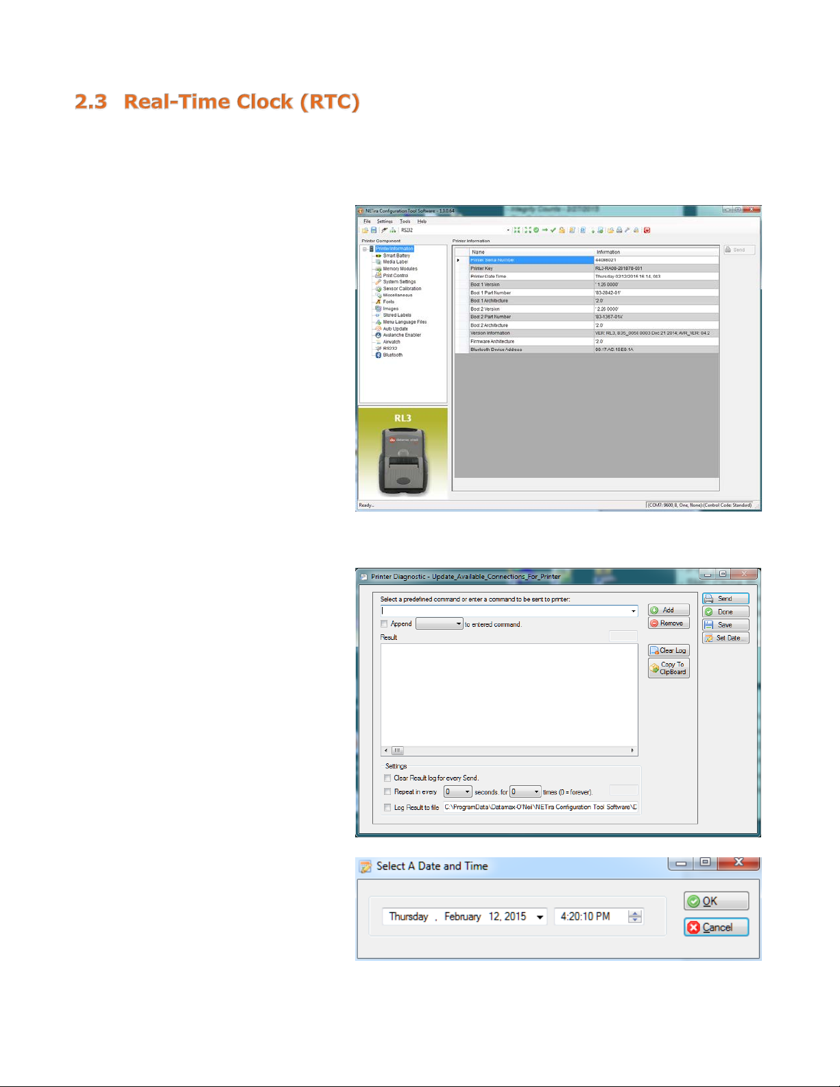
The Real-Time Clock is powered from a rechargeable coin cell. Once the RTC is set, and as long as the main
battery is in place and has a reasonable charge, the RTC will continue to keep time. If the main battery is
pulled, you have 2+ days or the time will be lost and will need to be reset once power is restored.
Viewing the RTC Setting:
1) Click on “Printer Information.”
2) View the current RTC date and
time stamp in “Printer Date
Time” section.
Resetting the RTC:
1) Click on “Printer Diagnostics.”
2) Click on “Set Date.”
3) Set the “Date” and “Time” and
click on “OK.”
www.datamax-oneil.com 12
Page 20

The RL Series printer displays will enter sleep mode after one (1) minute of inactivity; press any
NETira™ CT. When the printer is charging it will not “auto shutoff.”
Icon
Battery Charge Level. The number of bars and the % will change according to
progressing to show charging, unless at 100%
The Front Panel is an event-driven interface composed of a graphic
display and four (4) buttons. In addition to providing current printer
information, the mode-dependent panel allows the items in the main
display area and the button function s to change as operational events
require.
button to wake.
RL Series printers will turn off after 120 minutes of inactivity. This “shutdown” period can be
adjusted or disabled using the NETira
modifying the System Settings/System Power Down setting. See Sec tio n 3.3 for more information on
™
CT configuration program (Ver. 35 or greater) and by
3.1.1 LCD Icons
90%
remaining battery charge. During charging, the battery level is continuously
Wireless LAN Signal Strength.
The DC power supply is connected and the battery is charging.
IP: 192.168.0.1
IP address currently assigned to the printer (if equipped). If an IP i s no t assigned,
it will display as 0.0.0.0. Bluetooth
3.1.2 Audible Alerts
One (1) beep AC power supply disconnected
Two (2) beeps AC power supply connected
Function
®
models will display the MAC address.
Alert Event
Five (5) beeps Opened printer cover or Paper-out condition
Constant beep (10 seconds in duration) Failed download (via RS-232)
Short interval beep (for length of download) Downloading data (via Wireless LAN)
www.datamax-oneil.com 13
Page 21

Short Press: Wakes the printer from sleep or off mode.
Press and hold (~10 seconds): Resets the printer .
Short Press: Feeds one label or a preset paper length
Configuration Label with additional information.
3.1.3 Buttons
Ready Mode
Button Function
Short Press: Puts the printer into sleep mode.
Press and hold (~4 seconds) then release: Turns off the printer.
Press and hold for four (4) and seven (7) seconds and then release: Prints the Configuration
Label
Press and hold until printing starts [approximately eight (8) seconds]: Prints the
Enters the printer’s menu system.
Long Press (~4 seconds): Toggles the Wireless LAN/Bluetooth® radio on and off
Menu Mode
Button Menu Icon Function
Returns to the previous menu level, at the top level it will exit the menu system.
Scrolls downward to the next available menu item or menu branch.
Exits the menu system and returns to “Ready Mode.”
OK Selects the current highlighted item or menu branch.
3.1.4 Menu
Pressing the button allows entry into the printer’s menu system. The menu system is informational
only; configuration changes to the printer cannot be made via the menu. The menu consists of three
branches; default values are show next to each item.
Serial
Baud Rate 9600 BPS
Data Bits 8
Parity None
Stop Bits 1
Protocol Hardware
MAC Address xx:xx:xx:xx:xx:xx (varies for each printer; standard 6-octets of hexadecimal digits)
Calibrate Media The pri n ter is factory-calibrated and should not need further calibration. However,
certain types of aftermarket paper/media will need to be calibrated. Depending on the
media type being used, this function senses the gaps between labels or the black
mark on the back of the media. Once the printer senses these locations, it can
accurately position the media for printing at the start of each label.
Once selected, the printer will feed media, pause ~20 seconds and then complete the
calibration.
www.datamax-oneil.com 14
Page 22

Initiation of this mode causes the printer to print its Configuration Label . Th e Configuration Label provides
valuable printer information, including the firmware version, memory allocations, enabled options,
communications settings and label-counter data.
To print the Configuration Label:
1) Be sure the printer is properly loaded with media [at least four (4) inches wide] and that the power to
the printer is off.
2) Turn on the printer and allow it to reach a ready state.
3) Press and hold the button for four (4) to seven (7) seconds and then release. The printer will now
print the current configuration of the printer.
A printer connection to your host PC must be established before proceeding to set up the parameters of
the printer. The connection is established through various options included with the model you are using.
Below provides the setup based on your preference for conn ect ion type. Once connected, proceed to
Section 3.4 - NETira
the printer, as needed.
™
CT Printer Configuration Utility for adjusti n g the settings and parameters of
Serial Connection Setup
To set up, an RJ11 to Serial interface cable is required (optional).
Connect the RJ11 connector to the RL printer. The port is located on the side of the printer and designat ed
with COM printed on the port cover. Connector should click in place once secured.
Connect the serial-connector portion of the cable to your host computer’s serial port.
The printer will automatically be assigned to COM 1 location.
USB Connection Setup
To connect the printer via USB connection, an Internet connection may be required. You may also need
administrative access rights to your host computer for completing this installation. If you do not, you will
need to log off and log in under a profile that has such rights for your host computer.
To connect your printer to the host computer, a Standard Mini B to Standard USB A Printer Cable is
required (Optional: P/N: 210304-100).
To set up a USB connection on Windows
- Power up your printer once the cable connection is made. The Mini B connector is used for
connection to the printer. Connect to the port with the USB-symbol port cover.
- Connect the standard USB connector to an available USB port on the host Windows
®
OS 7.0 or later device:
®
PC.
- Your host computer should recognize the printer and begin “Adding Device Driver.”
www.datamax-oneil.com 15
Page 23

- If the setup operation does not start, locate the Devices and Printers section of the Control Panel
and select “Add a Printer.”
- Once initiated, select the printer model under Datamax-O’Neil Printers. If the model is not located,
follow the steps “Locate Driver thru Windows Update” and follow the instructions to complete the
installation.
- Once completed, you should see the RL Printer as an available printer from your host PC.
- The default setting will set up as a CDC Composite printer type.
Bluetooth® Connection Setup
Power on the printer and confirm that the wireless radio is on. The Radio icon should appear on the LCD
screen of the printer. If it does not and “Radio OFF” is displayed, press the Radio button on your printer
(insert Radio icon symbol) for five (5) seconds until “Turning on Radio” appears.
Next, follow your Host PC or device instructions for adding a new Bluetooth
You should not see the printer as an available printer from your Host PC. Once connected and the connection
is established, proceed to Section 3.4 - NETIra
™
CT Printer Configuration Utility.
®
device.
Wi-Fi – Wireless LAN
Before connection to the printer using Wi-Fi can be established, the printer must first be connected by using
one of the options listed above. Once the connection is established, proceed to Section 3.4 - NETIra
Printer Configuration Utility for Wireless LAN connections and use the configuration tool to complete the
setup. For advanced setup details, see Appendix C – Wireless LAN and Bluetooth
®
Setup.
™
CT
www.datamax-oneil.com 16
Page 24

The NETira™ CT Printer Configuration Utility (available for download at www.datamax-oneil.com) is a
Query Memory Modules
The NETira™ CT Printer Configuration Utility is designed to communicate to the printer using the DPL
DPL. To restore to your computer, use Tools>Set Input Mode function within NETira™ CT.
Windows®-based configuration utility that allows the user to make changes to the existing printer setup
via a serial, USB or Wireless LAN connection.
NOTE: Information shown for NETira™ CT reflects what is available on the current version of software
(v. 1.0.0.64). If you are using a version that is not the most current, some features or options may not
be available as shown.
Utility Features:
Allows Real-Time Control/Query of Printer Configuration
Define and Save Optimal Configurations for Applications
Saved Configuration s can be Shared with other Printers and Sent via Email
Download Files, Formats and Fonts
1) Once you have downloaded the software, follow the instructions as prompted to install it on your PC. Once
installed, launch the NETira
2) Ensure the battery is installed and the printer is “ON.” Connect the host to the printer (see Sectio n 2.2 -
Interface Connections).
For Serial and Bluetooth® Connections:
a) Query the printer by using the “Auto-Detect” button.
b) If the Auto-Detect is unsuccessful, close the “Open a
c) Once complete, click “OK” and then click the “Query
(or Auto) printer-language setting. This is the default setting for your printer when used for the first
time. If the printer has been set to any other input mode, the printer must be reset back to Auto or
™
CT Printer Configuration Utility.
This will connect to the printer and retrieve the
setting currently stored in the printer.
configuration file…” dialogue box and go to the
Settings dropdown menu and choose the RS-232
menu option. On this screen you can manually
select the port and its parameters.
Printer” button on toolbar. This will connect to the
printer and retrieve the setting currently stored in
the printer.
www.datamax-oneil.com 17
Page 25

For Wireless LAN Connections:
3) At this point you may browse the Printer Component
Close the “Open a configuration file…” dialogue box.
a) In the toolbar, Click on the “TCP/I P Configuration”
Icon .
b) In the “TCP/IP Configuration” dialogue box enter the
IP address of the printer and click “OK.” (The IP
address should be displayed on the home screen o f
the printer’s LCD).
c) In the toolbar, from the dropdown menu box, select
“TCP_IP.” Then click on the Query Printer Icon .
categories and make any changes necessary to the
printer configuration.
4) Once your changes are com plete, send the new settings
to the printer using the “Send” button.
NOTE: When using the “Send” button, only the changes
displayed on the current page will be sent.
The “Set current setting to printer” button will
send all changes made to all pages.
www.datamax-oneil.com 18
Page 26

Length” value to be set.
3.5.1 Selecting Media Type
To accommodate a variety of media types, the printer is equipped with t wo (2) sensors. A transmissive
sensor (for gap and notch-type label media) and a reflective sensor (for “black mark”-type label media).
Several media types and their proper sensor settings are shown below:
Media
Type
Gap Label Media
Notch Media
(Edge)
Notch Media
(Center)
Reflective Media
(Black Mark)
Continuous Media
Sensor
Setting
Gap Not Supported Gap Reflective
Continuous*
*Requires the
“Continuous Label
Most applications that use label media will use the default setting of “Gap.” However, if “black mark” or
continuous media is being used, this setting must be changed.
The Sensor Type setting can be changed using the NETira
the software utility at www.datamax-oneil.com
and download it from there to your computer’s hard drive.
™
CT Printer Configuration Utility. You can find
Follow the instructions on installing the utility to your PC.
Launch the NETira
™
CT Printer Configuration Utility and query (connect) to the printer.
1) Click on the “Media Label
Settings” printer component.
2) To ch an ge the different
parameters, select from the
pull-down values or key in a
value.
www.datamax-oneil.com 19
Page 27

Name
Value
New value
1
Continuous Label
425 Distance the printer will advance after pressing the FEED button.
2
Label Width (1/100
425 200 = 2-inch media
400 = 4-inch media
3
Maximum Label Length
800 Distance must be greater than the le ng th of your media, i.e. 1000=10
4
Sensor Type
Continuous
Gap = Labels with gap
Reflective = Labels with Q-Mark or black mark
Common Settings:
Length (1/100 inch)
inch)
(1/100 inch)
Distance is measured in 1/100 inch, i.e. 1000=10 inches.
300 = 3-inch media
inches
Continuous = Media with no gaps
3) After updating the “New Value”
columns, click the “Send”
button to send these changes
to the printer.
NOTE: NETira™ CT will change its column status from a green to an orange triangle when values are
modified and do not match current printer values. Query the printer settings and if the orange triangle is
still present, try sending the “New Value” again.
www.datamax-oneil.com 20
Page 28

3.5.2 Quick Media Calibration
The printer is factory-calibrated for operation with most media types (both gap and “black mark”). Try
your media without performing any calibration adjustments first; this will determine if the factory settings
are compatible. Only perform the calibration adjustments if you are experiencing media-registration
issues.
The Quick Media Calibration should be performed first, if it fails to detect your label media proceed to the
Manual Media Calibration procedure, see Section 3.5.3.
The Quick Media Calibration can be performed using the NETira
Section 3.4 for more information on NETira
It is recommended that the battery is charged to 50% or greater before starting media calibration.
Launch the NETira
1) Click on the “Sensor
Calibration” printer component.
2) Install your media in the
printer and click the “Quick
Media” button.
3) The printer will feed media
while the sensor is being
calibrated. At the end of the
process, the following message
will be shown, indicating a
successful calibration. Values
displayed in the “New Value”
column may change after a
calibration.
If the calibration is not
successful, repeat the
procedure. If the Quick Media
calibration continues to fail,
proceed to Section 3.5.3 -
Manual Media Calibration.
™
CT Printer Configuration Utility and query (connect) to the printer.
™
CT) or the front-panel menu (see Section 3.1).
™
CT Printer Configuration Utility, (see
www.datamax-oneil.com 21
Page 29

3.5.3 Manual Media Calibration
Manual Media Calibration is intended for use when Quick Media Calibration printer has failed to detect the
start of each label. This procedure performs a complete recalibration of the sensors and will optimize the
printer to your media. In some instances, you may need to perform a Quick Media Calibration after the
Manual Media Calibration to further optimize the printer’s sensor.
When updating the printer’s Firmware the sensor settings can be saved to a configuration file (see
Section 3.8) that will eliminate the need to recalibrate the printer.
Sensor calibration is needed to set either the black mark or the gap value of the media sensor on the
printer. The Manual Media Calibration can be performed using the NETira
(see Section 3.4 for more information on NETira
It is recommended that the battery is charged to 50% or greater before starting media calibration.
Launch the NETira™ CT Printer Configuration Utility and query (connect) to the printer.
™
CT).
Procedure for Gap-Type Media: (be sure the printer is set to sense Gap media, see Section 3.4.1).
1) Click on the “Sensor
Calibration” printer component.
2) Click the “Manual Media”
button to start the manualcalibration process.
Follow the instructions on the
following screen.
3) Select the “Interlabel/Gap”
radio button then click “OK.”
4) Load Stock: Place the face of
media over the sensor, close
the door, then click “OK.”
5) Load Special Backing Media for
Gap: Peel the label(s) off
backing and place the backing
over the sensor, close the door
and then click “OK.”
6) Remove Stock: Remove all
media from printer, close the
door and then click “OK.”
™
CT Printer Configuration Utility
www.datamax-oneil.com 22
Page 30

7) NETira™ CT will display a
message indicating the process
has finished.
In case of any error, a “FAILED
CALIBRATION” message will be
displayed. Repeat the process.
8) To confirm changes, observe
that Gap Back Value and Gap
Paper Value have changed.
Procedure for Black Mark Media:
1) Click on the “Sensor
Calibration” printer component.
2) Click the “Manual Media”
button to start the manualcalibration process.
Follow the instructions on the
following screen.
3) Select the Reflective radio
button, then click “OK.”
(be sure the printer is set to sense Black Mar k media, see Section 3.4.1).
www.datamax-oneil.com 23
Page 31

Printing Area
Q-Mark Area
Sensor
NOTE: A special media with black
marks is needed to perform this
calibration. See the image to the
right. A sample image is included
at the end of this document, it can
be printed and used for this
calibration procedure.
4) Load Stock: Place a white
section of media under the
sensor, close the door and then
click “OK.”
Sensor
5) Load Special Q-Mark Media for
Reflective Media: Place a black
section of the media under the
sensor, close the door and then
click “OK.”
6) Remove Stock: Remove all
media from printer, close the
door, then click “OK.”
www.datamax-oneil.com 24
Page 32

7) NETira™ CT will display a
message indicating that the
process has finished.
In case of any error, a “FAILED
CALIBRATION” message will be
displayed. Repeat the process.
8) To confirm changes, observe
that the Black Mark values
have changed.
www.datamax-oneil.com 25
Page 33

To set the printer to work in Presenter Mode, follow these steps:
- Set the “Presenter Sensor Equipped” parameter to enable the presenter sensor.
- Calibrate the Presenter Sensor to store the media settings (liner and media).
These setting changes can be performed using the NETira
3.4 for more information on NETira™ CT).
Launch the NETira
™
CT Printer Configuration Utility and query (connect) to the printer.
Enable the Presenter Sensor:
™
CT Printer Configuration Utility (see Section
1) Click on the “Miscellaneous”
printer component.
2) Set the “Present Sensor
Equipped” to Enabled.
3) After updating the “New Value”
column, click the “Send” button
to send this change to the
printer.
www.datamax-oneil.com 26
Page 34

1) Install the media in the printer
Media Backing
Calibrate the Presenter Sensor:
After calibration is complete, the presenter sensor will be disabled. You must re-enable the presenter
before use.
and route the liner through the
peeler door, see Section 2.3.1.
When the “FEED” key is
pressed, the label will be
peeled and presented for the
operator.
2) Click on the “Sensor
Calibration” printer component.
3) Click the “Presenter Sensor”
button to start the calibration
process.
Follow the instructions on the
following screen.
4) Type the number 6 as the
Advance Distance after
QMark/Gap. Click the “OK”
button.
This value may vary if
Datamax-O’Neil media is not
used and may require
adjustments to the Advance
Distance after QMark/Gap
parameter for the sensor to
work properly.
5) The f o llowing screen will be
shown. Click the “OK” button to
start the process.
After the calibration is
performed successfully, the
following confirmation screen
will be shown. If the sensor
calibration fails, repeat the
process.
NOTE: To test the proper operation of the printer, press the “Feed” button. The label is separated from
the liner and a message “REMOVE LABEL” is shown in the LCD. After the label is removed, the printer will
print the next label.
312
Peeler Door
www.datamax-oneil.com 27
Page 35

The NETira™ CT Configuration Utility can only communicate to the printer using the DPL printer-
Mode function within NETira™ CT.
The printer supports several printer languages, such as CPCL, ZPL, DPL, etc. However, the printer has an
AUTO input mode that will detect the type of script and switch to the desired printing language. By
default, the printer is configured as an AUTO mode. To manually change the printer language used,
perform the following steps.
These setting changes can be performed using the NETira
3.4 for more information on NETira™ CT).
™
CT Printer Configuration Utility, (see Section
Launch the NETira
1) Click on the “Systems Settings”
printer component.
2) Set the ‘Input Mode’ to the
desired emulation under the
“New Value” column.
3) After updating the “New Value”
column, click the “Send” button
to send this change to the
printer.
language input mode. If the printer has been set to use an input mode other than DPL, the printer’s
input mode must be changed back to Auto or DPL. This can be performed using the Tools>Set Input
™
CT Printer Configuration Utility and query (connect) to the printer.
www.datamax-oneil.com 28
Page 36

The NETira™ CT Printer Configuration Utility allows printer configuration files to be saved to a file. These
files can be useful for saving a printer configuration for a particular applicatio n or media. Saved
configuration files can be shared with other printers/users.
Saving and Loading a Configuration file can be performed using the NETira
Utility (see Section 3.4 for more information on NETira
Launch the NETira
™
CT Printer Configuration Utility and query (connect) to the printer.
™
CT).
To Save a Configuration File:
1) Once the printer has been
queried the current settings
can now be saved to a file.
You may also make changes to
any of the settings and have
these values saved, as well.
2) To sav e the current
configuration in a file, go to
“File/Save As” menu and
specify the filename.
The current settings will be
saved in a file with extension
“.cfg”.
™
CT Printer Configuration
To Load a Configuration File:
1) To open a saved configuration,
go to the “File/Open” menu and
choose the configuration
filename.
Optional: Check “include
Sensor Calibration Data on
Open” box to import sensor
data with the configuration.
Sensor data is printer-specific
and should only be imported to
the printer that it came from.
2) The conf iguration will now be
loaded to NETira
™
CT.
www.datamax-oneil.com 29
Page 37

There are two (2) ways to send demo-label formats to the printer, NETira™ CT and the standalone Printer
Demo program available for download at www.datamax-oneil.com
NETira
™
CT Printer Demo:
1) Launch the NETira™ CT Printer
Configuration Utility, select “Tools,” then
“Printer Demo.”
2) B r ow se to fo lder containing print files,
highlight files to be printed and click
“Add>.”
3) Click on “Print” to send the file(s) to the
printer.
Standalone Printer Demo:
.
1) Launch the Printer Demo utility.
2) Select the file to print from the dropdown
menu.
3) Select “Settings” to set the
communication parameters for the
communication type selected.
4) Click “Print Demo” to send the file to the
printer.
www.datamax-oneil.com 30
Page 38

It is recommended that the configuration be saved before downloading Firmware and restored when
the configuration. See Section 3.8 for instructions.
It is recommended that the configuration be saved before downloading Firmware and restored when
the configuration. See Section 3.8 for instructions.
When program updates and/or new features are added, they can be downloaded to the printer as
follows:
1) Identify the new version for your model of printer from the Datamax-O’Neil website at
www.datamax-oneil.com
RL4/RL4e firmware files are not interchangeable.
2) Launch the NETira™ CT Printer Configuration Utility and query (connect) to the printer (see Section
3.4 for more information on NETira™ CT). NOTE: To update your firmware, the NETira™ Printer
Configuration Utility program is required. Go to www.datamax-oneil.com
computer’s hard drive if you have not done so already.
and download it onto your computer’s hard drive. NOTE: RL3/RL3e and
and download it onto your
3) Go to the Tools>Upgrade>Firmware.
4) Click the “Send” button to start the
finished. Be sure to check the box labeled “Include Sensor Calibration Data on Open” when restoring
Select the binary file (BIN file).
firmware update.
Loading Boot 1 and Boot 2 and Firmware
Loading Boot Firmware requires a serial connection to the printer.
1) Connect the printer to your PC using a serial cable.
2) Launch the NETira™ CT Printer Configuration Utility and query (connect) to the printer (see Section
3.4 for more information on NETira
finished. Be sure to check the box labeled “Include Sensor Calibration Data on Open” when restoring
Go to the Tools>Upgrade>Firmware. Select the binary files (BIN fil es) for each of the Boot files.
3)
4) Check the “Select and Download Boot 1 file:”, “Select and Download Boot 2 file:” and “Erase System
and/or User Area” boxes and click “Send” to initiate the download.
™
CT).
Always check the “Erase System and/or User Area” box unless otherwise instructed.
5) Once the Boot Loader fil es hav e been loaded, the firmware version can be updated using the
procedure outlined in Section 3.10.
www.datamax-oneil.com 31
Page 39

This section details the cleaning, adjusting and troubleshooting tips for the RL Series printer. Proper
cleaning is critical. To maintain peak performance of the printer, Datamax-O’Neil offers a complete line of
cleaning products, including pens, cards, films and swabs. Visit www.datamax-oneil.com
The following table outlines the recommended maintenance schedule for the various printer parts.
Area Method (Std. Models) Method (Linerless Models) Interval
to learn more.
Printhead
Platen Roller
Peel-Off Roller Cleaning Pens Cleaning Pens After 3-5 rolls of media
Lid Roller
Media Sensor Compressed Air Compressed Air Monthly
Interior
Cleaning Card or Cotton
Swab w/Isopropyl Alcohol
Cotton Swab
w/Isopropyl Alcohol
Cotton Swab
w/Isopropyl Alcohol
Compressed Air Compressed Air As Needed
Cleaning Pens After 3-5 rolls of media
Cleaning Pens After 3-5 rolls of media
Cleaning Pens After 3-5 rolls of media
Isopropyl alcohol is a flammable solvent; always take the proper precautions when using this
substance.
To achieve optimum print quality and maximum printhead life, Datamax-O’Neil specifies the use of
Datamax-O’Neil-brand media and ribbons. These supplies are specially formulated for use in D-O printers;
use of non-Datamax-O’Neil supplies may affect the print quality, performance and life of the printer or its
components. For a current list of approved media and ribbons for use in direct-thermal and thermaltransfer applications, please contact a Media Representative at (407) 523-5650.
www.datamax-oneil.com 32
Page 40

If print quality declines (symptoms include non-compliant bar codes, print dropouts and streaks),
External Media Door
Cleaning Card
the typical cause is debris buildup on the printhead. Furthermore, when the buildup is not
removed it may lead to reduced service life or printhead failure. Streaks in printed labels usually
indicate a dirty or faulty printhead.
To clean the printhead (using a Datamax-O’Neil cleaning card):
The following procedure is for “standard configuration” printers. Linerless printers should only be
cleaned with the Datamax-O’Neil Cleaning Pens.
1) Open the pri n t er Cov er. Remove any media installed in the printer. Open the External Media Door
located in the bottom of the printer.
2) Remove the cleani n g card from its package. Insert the cleaning card through the External Media
Door and into the printer as shown:
www.datamax-oneil.com 33
Page 41

Cleaning Card
Cover
STEP 1
STEP2
3) Close the Cover and then Press the button several times until the cleaning card has been
completely fed through the printer. Repeat if necessary.
Feed Button
4) Reload the media. Close the Cover, push down until it latches closed. Press the button to
normalize tracking.
To clean the printhead (using Datamax-O’Neil Cleaning Pens #770189-000):
The Cleaning Pens are typically intended for use on linerless-model printers or any printer with adhesive
buildup. They are used to clean components that are exposed directly to adhesive. Two pens are included
in the kit, the first pen “Step 1” breaks up the adhesive and the second pen “Step2” removes it.
The pen’s end cap has a plastic scraper to remove large
buildup of adhesive from the printhead and other parts.
NOTE: DO NOT USE ON THE PLATEN ROLLER OR
SENSORS.
www.datamax-oneil.com 34
Page 42

Occasionally, situations arise that require troubleshooting. Possible problem situations and potential
solutions are listed below. Contact a qualified technician for problems that persist or problems not covered
in this section.
Contact Datamax-O'Neil Customer Service for further details.
For further details regarding parts availability and where to buy, contact Datamax-O'Neil by Honeywell
Customer Service.
The following section lists the symptoms and the associated User’s Guide Sections for the topics covered.
While not every situation is addressed, you may find some tips helpful. After a corrective action is taken,
press the button to clear the alarm.
Unacceptable print quality:
Dirty printhead: Clean the printhead (see Section 4.2).
The temperature setting may be incorrect for the media being used. Use the NETira™ CT Printer
Configuration Utility or software commands to adjust the Heat Setting and Print Speed.
Faulty printhead: Call for service.
The printer does not print or prints several labels at once:
The labels are incorrectly loaded: See the loading instructions in Section 2.3.
The media is not calibrated: Calibrate it as directed in Section 3.5.
The media sensor or sensor circuitry may be defective: Call for service.
Skips every other label or occasionally skips labels
The label is formatted too close to the top edge of the label: Leave white space equal to 8-dot
rows [about 0.02 inch (0.5 mm)] at the top of the label.
The media is not calibrated: Calibrate it as directed in Section 3.5.
The media sensor or media-sensor circuitry may be defective: Call for service.
Unable to print rotations:
The characters are formatted outside the dimensions of the label: Check that the row/column
values provide enough room for the height of the image being printed.
www.datamax-oneil.com 35
Page 43

Light print on the right side of the label:
The printer’s cover is not latched down: Latch it.
The printhead is not properly aligned: Call for service.
Printer fails to power ON:
The battery may need to be charged: Charge the battery (see Section 2.1).
For RL3/RL3e models, make sure the printer is turned on (see Section 3.1.3).
Label advances eight (8) inches before a fault indication:
The media may not be properly loaded: Reload it (see Section 2.3). When loading media ensure
that the supply hubs are against the media and that gaps or marks in the labels are in line with
the media sensor.
The media sensor or media-sensor circuitry may be defective: Call for service.
Labels move excessively from side to side during printing:
The media may not be properly loaded: Reload it (see Section 2.3). When loading media ensure
that the supply hubs are against the media and that gaps or marks in the labels are in line with
the media sensor.
When using Peeler Mode, slack in backing (liner) material occurs:
With some types of media it may be necessary to periodically remove slack in the liner material
that accumulates before the Peeler Door. To remove: Hold the Peeler Door closed and pull on the
liner material until the slack is removed and the liner is tight.
For list of possible error codes and conditions, please refer to Appendix E.
www.datamax-oneil.com 36
Page 44

Dimensions
RL3/RL3e: 5.6” w x 7.6” h x 3.2” d (142 x 193 x 81 mm)
RL4/RL4e: 6.5” w x 7.9” h x 3.2” d (166 x 200 x 81 mm)
RL4/RL4e: 2.16 lbs. (0.98 kg)
Drop Specifications
6 ft. (1.8 m)
Four (4)-button user interface
Operating Temperature
-4°F to 122°F (-20°C to 50°C)
Storage Temperature
40°F to 140°F (-40°C to 60°C)
Charging Temperature
40°F to 104°F (5°C to 40°C)
Relative Humidity
10% − 90% non-condensing
ESD Protection
RL4/RL4e: 8kV Air/ 6kV Contact; RL3/RL3e: 6kV Air/6kV Contact
Printhead
Direct thermal; 203 dots per inch (8 dots per mm)
RL4/RL4e: 4.125” (105 mm)
Print Speed
4” per second (102 mm per second)
Installed Memory
RLe: 64 MB RAM/128 MB Flash
RL: 32 MB RAM/64 MB Flash
Media Types
RL3/RL3e: 1.00”– 3.125” (26 – 79 mm)
sensing. External fanfold or roll supply.
Media-Thickness Range
2 mil – 6.5 mil
Media-Roll Capacity
2.65” (67 mm) O.D. on 0.75” (19 mm) I.D. core
Physical Characteristics
Weight (printer only):
User Interface
User Environment
Print Technology
Print Width
Memory
RL3/RL3e: 1.95 lbs. (0.88 kg)
128 x 64 LCD display with white LED backlighting.
RL3/RL3e: 2.8” (72 mm)
Media
RL4/RL4e: 2.00”– 4.12” (51 – 105 mm)
Linered and linerless (if equipped) labels with black mark or gap
www.datamax-oneil.com A-1
Page 45

Serial Interface
RS-232, up to 460.8 kbps
USB Interface
2.0 (full speed)
Bluetooth Interface
Supported versions: Version 4.0 LE, Class 2; Serial-port profile
Authentication: LEAP, EAP-PEAP, EAP-FAST, EAP-TTLS, EAP-LEAP:
Network Support
DHCP, TCP, UDP, DNS, BOOTP
Battery
14.8V Lithium-ion, 2200 mAh (33 W-h)
External charge contacts, 11-15V, built-in spike and surge protection
Recharging
4-6 hours
eight (8) continuous hours.
Communications
Wireless LAN
Network standard: IEEE 802.11 a/b/g/n with Dual Radio
Wireless access modes: Infrastructure and ad-hoc
Security Protocols: WEP (64/128), WPA (TKIP/RC4), WPA2 (CCMP/AES)
Power Source
DC Inputs
RL3 Endurance
RL4 Endurance
Smart Battery External DC jack, 11-15V, built-in spike and surge
protection
Prints more than 5,500 3”x1” (76.2 x 25.4 mm) labels when operating
Prints more than 320 4”x6” (100 x 150 mm) labels when operating 16
continuous hours.
Barcodes/Fonts/Graphics
The printer is equipped with the most-popular industry fonts and bar codes; see the Programmer’s Manual
for full listings and detailed information.
• Scalable Fonts:
- CG Triumvirate
character support from Monotype Imaging
• Standard fonts:
- 5.5CPI, 7.2CPI, 10.2 CPI, 10.7CPI, 18.5CPI 20.4CPI, 22.6CPI, 34.0CPI, OCR-A, OCR-B (additional fonts
available)
• Downloadable font types:
- True Type, Bitmap
• Character Sets:
- Unicode/UTF8 support; 50 international symbol sets, Big 5, JIS and Shift JIS, and more
• Optional characters:
- Arabic, Greek, Hebrew, Unicode subset, including Latin
- Asian (including Big 5, Simplified Chinese, Kanji, Hangul and Shift JIS); additional international
characters available
• Barcodes:
- Linear: Codabar, Code 3 of 9, Code 93, Code 128, EAN-8, EAN13, Interleaved 2 of 5, HIBC, PLESSEY,
MSI/Plessey, UCC/ EAN-128, UPC-A, UPC-E, UPC 2- and 5-digit addendums, Postnet, Telepen, UPS
MaxiCode, FIM, USD-8
- 2D Symbologies: PDF417, Aztec, QR Code, GS1, Datamatrix, TLC39, MicroPDF417
• Graphics:
- Supports storage of graphics/logos in Flash memory and transient “print once” graphic
TM
Bold Condensed, CG Triumvirate & CG Times with Cyrillic, Greek, Arabic and Hebrew
www.datamax-oneil.com A-2
Page 46

Software/Firmware
• NETira™ CT Configuration Tool - complete printer set-up utility
• Control Language Compatibility:
- NETira
- NETira
- EZ-Print, DPL, ZPL II
• Device Management Support and Compatibility:
- NETira™ Remote Management: Monitor and manage printers
- NETira™ MD: Mobile Device Management Utility for Smart Mobile Devices
- NETira™ Connector (CA): Access AirWatch
- Skyze and QualSoft MDM
• Network Compatibility
- TCP-IP based networks
- AS/400 (LPD)-based networks
• O/S Support:
- Windows® CE x/6.x to 6.0, Windows® Mobile and Android O/S
• Label design software compatibility:
- BarTender®, Niceware/NiceLabel and others
• ERP Systems:
- SAP, Oracle
• Software development kit:
- Android 2.1 and above, IOS 5,6 and 7
- Microsoft Windows
- C++, C Sharp, Java, Active X Control
™
MS – Menu Scripting
™
LD – Label Design Software
®
, CPCL, IPL, XML (limited)
®
Desktop up to Windows® 8, Windows® 8 Store, Windows® Mobile and Windows® CE
®
Mobile Device Management Console
www.datamax-oneil.com A-3
Page 47

To achieve optimum print quality and maximum printhead life, Datamax-O’Neil specifies the use of
applications, please contact your Datamax-O'Neil Media Representative.
Direct Thermal Linered/Linerless Labels - 0.75" Core ID, 2.65" Roll O.D.
Direct Thermal Linered/Linerl ess Labels and Receipt Paper - Im ageP ro Labels - Standard with Permanent Adhesive
Approx.
LBS/CTN
740854-912
2.0" x 1.0" Die Cut (0.125" gap) - PERM
14
50
645
740855-909
3.0" x 2.0" Die Cut (0.125" gap) - PERM
14
50
340
740855-202
*Linerless/REM 3.0" x 113'
33
30
N/A
740855-203
*Linerless/PERM 3.0" x 113'
33
30
N/A
Direct Thermal Linered/Linerless Labels and Receipt Paper - 0.75" Core I.D., 2.65" Roll O.D.
Direct Thermal Linered/Linerl ess Labels and Receipt Paper - Im ageP ro Labels - Standard with Permanent Adhesive
Approx.
LBS/CTN
740854-914
4.0" x 2.0" Die Cut (0.125" gap) - PERM
15
50
370
740854-915
4.0" x 3.0" Die Cut (0.125" gap) - PERM
15
50
245
740854-203
*Linerless/PERM 4.0" x 85'
33
30
N/A
*Must be used in linerless capable R L S eries printers. PERM = Permanant A dhesive.
Contact your sales representative for details.
Direct Thermal Receipt Paper - 0.75" Core ID, 2.65" Roll OD
Approx.
LBS/CTN
RL3e
740855-102
Premium - 3.0" x 164' - Continuous
8
50
N/A
RL4e
Datamax-O’Neil brand media. These supplies are specially formulated for use in our printers; use of nonDatamax-O’Neil supplies may affect the print quality, performance and life of the printer or its
components.
For a current list of approved media and ribbons for us e in direct-thermal and thermal-transfer
Part Number Width x Length
Part Number Width x Length
740854-916 4.0" x 4.0" Die Cut (0.125" gap) - PERM 15 50 185
740854-910 4.0" x 6.0" Die Cut (0.125" gap) - PERM 17 50 123
740854-202 *Linerless/REM 4.0" x 85' 33 30 N/A
Rolls/CTN Labels/Roll
Rolls/CTN Labels/Roll
Part Number Width x Length
740854-102 Premium - 4.125" x 171' - Continuous 9 50 N/A
www.datamax-oneil.com B-1
Rolls/CTN Labels/Roll
Page 48

Cleaning Pens and Cards - For Adhesive Applications
Approx.
LBS/CTN
Pens/Cards per CTN for
770189-000
RL3, RL3e, RL4, RL4e Label
10
2 Part Cleaning Pen
Part Number Printer Models
A two-step process designed to remove adhesive residue and give the thermal printhead, rollers and
paper path a thorough cleaning.
Each step involves inserting a chemically saturated card into the paper path. Step one will remove
adhesive residue.
Step two will remove any chemical residue remaining from the Step one card as well as all dirt and other
contaminates from the thermal printhead, rollers and paper path. Sold in carton quantities.
Step 1 and Step 2
www.datamax-oneil.com B-2
Page 49

AC Adapters - Battery Chargers
Multi-Bay Charger (Includes High Capacity AC Adapter and Multi-Unit Charging Adapter for multi-unit models)
Multi-Bay Charging Kit, RL series, 3-Upright Unit & 2 Battery Depot Charger, US
Plug
Communication Cables
Accessories
Part# Description
220515-100 AC Adapter for Charging with U.S. plug
220516-100 AC Adapter for Charging with EU plug
220517-100 AC Adapter for Charging with UK plug
220521-100 AC Adapter for Charging with Swiss plug
220518-100 AC Adapter for Charging with AU plug
220282-000 DC/DC Voltage converter (12v-60v)
220207-200 Vehicle Charge Cable Kit, [10 ft (3 m)]
510116-001 Cigarette Lighter Vehicle Power for Thermal Printers
220275-000 Battery Charging Cradle (2 bay)
550046-001 Spare Battery
220284-000 Multiple Unit Charging Adapter with Power Supply (1 to 4), US Plug
220285-000 Multiple Unit Charging Adapter with Power Supply (1 to 4), EU Plug
220286-000 Multiple Unit Charging Adapter with Power Supply (1 to 4), UK Plug
229028-000 Multi-Bay Charging Kit, RL series, 4-Upright Unit Depot Charger, US Plug
229029-000
229030-000 Single Charger Stand, RL Series - AC not included
210304-100 USB Cable (mini B to USB-A)
210164-100 Cable, Coiled, Right Angle, DB9 F
210191-101 Cable DB-9 F [7 ft (2.1 m)]
230112-000 RL Series Universal Mounting Bracket
280656-000 RL Series Belt Clip
210305-000 RL Series Belt Loop
210300-000 RL Series Hand strap
210302-000 RL Series Shoulder Strap
750332-000 RL3 / RL3e IP54 Case
220280-000 RL Series "RAM Mount" compatible Adapter and Ball
280711-000 External Media Spacer - RL3 / RL3e
280688-000 External Media Spacer - RL4 / RL4e
www.datamax-oneil.com B-3
Page 50

1) Turn the printer ON and connect it to the
The printer makes IP requests at power-up, so before making a network connection to the printer consider
how your IP addressing needs to be assigned. The IP addressing of the printer can be configured in one of
two ways: Using a static IP Address or Using IP Discovery (DHCP, BootP or RARP).
Default Network Settings:
The following table lists some of the printer’s default network settings. Any of these parameters can be
modified using the NETira™ CT Printer Configuration Utility program. )See Section 3.4 for more information
on NETira
™
CT.)
computer using the USB cable.
3.3 - Establishing Printer Connection
2) Install and Open the NETira™ CT Printer
Configuration Utility application on your PC (see
Section 3.4 for more information). This
configuration utility can be downloaded from our
website
3) Query the printer by using the “Update Available
Connection For Printer”. This will look for the
“USB Virtual COM Port.” Once it is completed,
reopen the dropdown menu and select the
assigned port. If the printer fails to detect the
USB Virtual COM port, check “Click on Settings”
and select the COM port that is assigned to the
Datamax-O’Neil USB CDC Class Device COM port.
NOTE: The message “Done query printer”
confirms that the communication process was
successfully executed.
.
Refer to
Section
.
www.datamax-oneil.com C-1
Page 51

printer.
The printer can be configured to use a static IP or a dynamic IP obtained from a DHCP server.
Using a Dynamic IP Address (DHCP):
1) Click on the “Wireless General
Network” printer component.
2) Change (or confirm) the
following parameter setting:
IP address method: DHCP
3) After updating the “New Value”
column, click the “Send” button
to send these changes to the
printer.
Values obtained from the DHCP server will be shown under the fields: Active IP address, Active
Subnet Mask and Active Gateway.
Using Static IP Address:
1) Click on the “Wireless General
Network” printer component.
2) Change (or confirm) the
following parameter settings:
IP address method: Static
Static IP address: According to
your network IP range.
Static Subnet mask: According
to your network subnet mask.
3) After updating the “New Value”
column, click the “Send” button
to send these changes to the
www.datamax-oneil.com C-2
Page 52

1) Click on the “Wi-Fi” printer
component.
2) Change (or confirm) the
following parameter settings:
ESSID: (Default: D-O) Type name
that matches the name of your
access point.
Network Type: Infrastructure or
Ad-hoc.
3) After updating the “New Value”
column, click the “Send” button
to send these changes to the
printer.
NOTE: To validate a successful Wireless LAN connection, the IP address obtained from the access point
will be shown on the LCD display of the printer.
www.datamax-oneil.com C-3
Page 53

1) Click on the “W-Fi” printer
printer.
The printer can be configured to utilize several Wireless LAN securi ty protocols. The following sections
outline the most popular configurations.
B.4.1 WEP 64 & 128 Bit
component.
2) Click the “Static WEP” radio
button.
3) Change (or confirm) the
following parameter settings:
WEP Selected Key: Select the key
number to use.
WEP AP authentication:
Users share 40-bit = 64-bit
encryption.
Users share 128-bit = 128-bit
encryption.
WEP Data Encryption:
Enable WEP Data Encryption.
WEP Key #1-4:
Enter the WEP keys that match
values used in the access point.
4) After updating the “New Value”
column, click the “Send” button
to send these changes to the
www.datamax-oneil.com C-4
Page 54

1) Click on the “Wi-Fi” printer
printer.
1) Click on the “Wi-Fi” printer
printer.
C.4.2 WPA2-PSK w/CCMP
component.
2) Click the “Click the WPA/WPA2”
radio button.
3) Change (or confirm) the
following parameter settings:
Group Cipher: CCMP
Network Authentication Type:
WPA2-PSK
4) Type the Pass Phrase under t he
“WPA_PSK_TKIP/WPA2_PSK
settings” section. Note that Pass
Phrase is case-sensitive.
5) After updating the “New Value”
column, click the “Send” button
to send these changes to the
C.4.3 WPA2-PSK w/TKIP
component.
2) Click the “Click the WPA/WPA2”
radio button.
3) Change (or confirm) the
following parameter settings:
Group Cipher: TKIP
Network Authentication Type:
WPA2-PSK
4) Type the Pass Phrase under the
“WPA_PSK_TKIP/WPA2_PSK
settings” section. Note that Pass
Phrase is case-sensitive.
5) After updating the “New Value”
column, click the “Send” button
to send these changes to the
www.datamax-oneil.com C-5
Page 55

C.4.4 WPA2-Enterprise
1) Click on the “W-Fi” printer
component.
2) Click the “Click the WPA/WPA2”
radio button.
3) Ch an ge (or confirm) the
following parameter settings:
Network Authentication Type:
WPA-Enterprise
Phase 2 Method: EAP-MSCHAPv2
EAP Type: Select EAP-PEAP
NOTE: EAP Type can be variable.
Other values supported: EAP-LEAP,
EAP-TTLS, EAP-PEAP and EAPFAST.
4) Type the username and
password under the “WPA/WPA2
Enterprise” section.
5) After updating the “New Value”
column, click the “Send” button
to send these changes to the
printer.
www.datamax-oneil.com C-6
Page 56

1) Click on the “Wi-Fi” printer
printer.
C.4.5 WPA-PSK TKIP w/TKIP
component.
2) Click the “Click the WPA/WPA2”
radio button.
3) Change (or confirm) the
following parameter settings:
Group Cipher: TKIP
Network Authentication Type:
WPA2-PSK_TKIP
4) Type the Pass Phrase under the
“WPA_PSK_TKIP/WPA2_PSK
settings” section. Note that Pass
Phrase is case-sensitive.
5) After updating the “New Value”
column, click the “Send” button
to send these changes to the
www.datamax-oneil.com C-7
Page 57

1) Click the Bluetooth® menu item in
In the event of a Wireless LAN communication problem (drop-offs, hangs, can’t communicate, etc.), the
printer can be reset.
To reset the printer:
1) Press and hold the button until the “Radio Off ” message is di splayed and then release.
2) Next, press and hold the button until the “Turning Radio On” message is displayed and then
release.
The printer will reboot and attempt to connect to the network device using the parameters previously
set in the printer.
As an alternate method, remove the battery from the printer, wait 20 seconds and then reinstall the
battery. See Section 2.1.
The printer is configured with default factory settings. To determine your printer's configuration, print a
Configuration Label (see Section 3.2).
the Printer Component section of
the configuration utility.
2) To set up the printer for
Bluetooth
®
, change (or confirm)
the following parameter settings:
Bondable: Yes
Connectable: Yes
Discoverable: Yes
PassKey: Default “0000” (must
match entry used on
host computer)
3) After updating the “New Value”
column, click the “Send” button to
send these changes to the printer.
4) Allow 30 seconds for the printer to
reset. For connection to the
printer, please refer to the
instructions included with your
Bluetooth
®
adapter or host
computer/handheld.
www.datamax-oneil.com C-8
Page 58

The printer can be connected to a PC or a handheld device using a USB cable. Before connecting the
printer to your host device, the type (or class) of USB connection must be determined. There are three (3)
classes of USB connections that are supported:
CDC (Communication Device Class, virtual COM port via emulated RS-232)
Printer Class (Typical Windows
Composite Class (CDC + Printer Class)
Whenever possible, it is recommended to use the Composite Class, as it gives the most flexibility.
However, on some systems (e.g., handheld devices) CDC or Printer Class alone should be selected, as
handheld devices have limited support.
Software/Files Needed:
The following files can be downloa ded from: www.datamax-oneil.com
NETira™ CT Printer Configuration Utility
Qualsoft
Windows® Drivers (for Printer and Composite Class installations only)
“Datamax-O'Neil Windows Printer Drivers” (for Printer Class installations only)
“Datamax-O'Neil CDC Class.inf” file (for CDC installations only)
Create a new folder on your local computer named “Drivers.” Download the necessary files and place them
in this folder.
®
Printer)
www.datamax-oneil.com D-1
Page 59

1) Turn the printer ON and connect it to the
successfully executed.
4) Click on the “Miscellaneous” printer
Before attempting a USB connection the printer must first be configured to use the desired USB class. Set
the printer to appropriate USB class for your particular application by using the NETira
Configuration Utility.
The default setting is “Composite (CDC/Printer Class).”
™
CT Printer
computer using the USB cable.
Refer to
Section 3.3 - Establishing Printer
Connection
.
2) Install and Open the NETira™ CT Printer
Configuration Utility application on your PC
(see Section 3.4 for more information).
This configuration utility can be
downloaded from our website
.
3) Query the printer by using the “Update
Available Connection For Printer.” This will
look for the “USB Virtual COM Port.” Once
it is completed, reopen the dropdown
menu and select the assigned port. If the
printer fails to detect the USB Virtual COM
port, check “Click on Settings” and select
the COM port that is assigned to the
Datamax-O’Neil USB CDC Class Device
COM port.
NOTE: The message “Done query printer”
confirms that communication process was
component.
5) Change (or confi rm ) the USB Mode
parameter setting.
6) After updating the “New Value” column,
click the “Send” button to send this change
to the printer.
7) Proceed to the appropriate section to
complete the USB connection.
Section C.3, Composite Class
Section C.4, CDC Class
Section C.5, Printer Class
www.datamax-oneil.com D-2
Page 60

2) Go to Windows® Desktop and click on “Device
Composite (CDC/Printer Class) can be accomplished by updating the Windows® printer list.
1) Do not plug the USB cable into the computer’s USB port. If you have done so, unplug it now.
and Printers.”
3) Click on “Add a printer.”
4) Click “Add a local printer.” Then, click “Next.”
5) Select “Use an existing port.” NOTE: Try setting
it for a COM Port higher than COM4.This can be
updated once the printer and CDC drivers have
been installed, if needed.
www.datamax-oneil.com D-3
Page 61

6) Scroll through the “Manufacturer” list and
Step 6 once the update is completed.
click on “Datamax-O’Neil.” Scroll through
“Printers” and select the applicable printer.
NOTE: If Datamax-O’Neil or the correct
printer does not appear in the selection
boxes, click on “Windows Update” and repeat
www.datamax-oneil.com D-4
Page 62

7) If the printer drivers were previously installed
you may see this screen. Choose the setting
that applies and click “Next.”
8) You can use the default or type in a printer
name, click “Next.”
9) Share or do not share the printer, click “Next.”
www.datamax-oneil.com D-5
Page 63

10) Uncheck or check the box “Set as the default
printer,” then click “Finish.” Do not print a test page.
11) Connect the USB cable to your printer and host PC.
Right-click on your printer and select printer
properties. Click on “Print Test Page.” If the print test
does not print, verify that the printer Com Port and the
USB CDC class device COM Port match.
www.datamax-oneil.com D-6
Page 64

12) To verify, right-click on the printer and select “Printer
Properties.” Next, click on the “Ports” tab. Verify that
the Printer COM Port and the USB CDC Class Device
COM Port match. To update the printer COM Port,
select the port that matches the USB CDC Class device
COM Port, then click “Apply” and “OK.”
www.datamax-oneil.com D-7
Page 65

1) Turn on the printer and wait
Once the printer is installed following the process in Section C.3, both the printer driver and USB CDC
drivers are installed. If the requirement is for CDC only, you need to update the printer User Mode using
the NETira
2) Open the NETira™ CT Printer
3) Query the printer by using the
4) Click on “Miscellaneous” and
5) Press “Send.”
™
CT Printer Configuration Utility.
until the “Ready” screen
appears. Connect the USB cable
to the PC.
Configuration Utility.
“Auto Detect” button. This will
connect to the printer and
retrieve the settings currently
stored in the printer. If the
printer fails to “Auto Detect,”
check your RS-232 settings to
ensure you have the correct
COM Port selected.
change the “USB Mode” to “CDC
Class.”
www.datamax-oneil.com D-8
Page 66

1) Turn on the printer and
Once the printer is installed following the process in Section C.3, both the printer driver and USB CDC
drivers are installed. If the requirement is for Printer Class only, you need to update the printer User
Mode using the NETira
wait until the “Ready”
screen appears. Connect
the USB cable to the PC.
2) Open the NETira™ CT
Printer Configuration Utility.
3) Query the printer by using
the “Auto Detect” button.
This will connect to the
printer and retrieve the
settings currently stored in
the printer. If the printer
fails to “Auto Detect,” check
your RS-232 settings to
ensure you have the correct
COM Port selected.
™
CT Printer Configuration Utility.
4) Click on “Miscellaneous”
and change the “USB Mode”
to “Printer Class.”
5) Press “Send.”
www.datamax-oneil.com D-9
Page 67

Code
Conditions Listing
0
No Conditions
1
Remove a Label
2
Waiting for a GPIO Signal
3
Thermal Printhead is Warm
4
Print Engine is Calibrating Sensors
5
FLASH is being Erased
6
FLASH is being Written
7
Network is Being Initialized
8
Print Engine is NOT Calibrated
9
Parser is in HEX DUMP Mode
10
Verifier/GPIO Mode
11
Print Engine in Print Test Rate Mode
12
Waiting for Additional Data
13
Motor is Warm
14
RFID is Active
15
Paper is Out
16
Battery is Charging
17
Battery is Dis-Charging
18
Wired Ethernet - 802.3 - Is Active
19
Wireless Ethernet - 802.11 - Is
Active
20
Bluetooth® - 802.15 - Is Active
21
Battery Charging
22
AC Plugged In
23
WIFI Attempting to Connect
24
WIFI Radio is OFF
NOTE: Codes listing is for notification information only; no user interaction required.
www.datamax-oneil.com E-1
Page 68

Code
Warning Listing
100
No Warnings
101
Ribbon Is Low
102
TPH Needs Cleaning
103
RFID Write Warning
104
Changes are Pending
105
Low Voltage
106
Power Down Imminent
107
Rewinder Full
108
Thermal Printhead Mismatch
109
High Voltage
110
Media Low
111
Battery Low
NOTE: Represents Warning notification and may require some action by user.
www.datamax-oneil.com E-1
Page 69

Code
Fault Listing
200
No Faults
201
System Fault
202
ADC Fault
203
Thermal Printhead UP
204
Ribbon Fault
205
Top Of Form Fault
206
Stock (Paper) Fault
207
Cutter Fault
208
Verifier Fault
209
Ribbon-Saver Fault
210
Positioning Fault
211
Thermal Printhead Fault
212
DMA (SPI) Data Transfer to TPH Fault
213
Print-Engine Fault
214
Motor-Too-Hot Fault
215
TPH-Too-Dirty Fault
216
Scanner Fault
217
Present-Sensor Fault
218
TPH-DOT-Failure Fault
219
Radio-Frequency-ID Fault
220
Label-Rewinder Fault
221
Feed-Clear Fault
222
Close Thermal Printhead Latch Fault
223
Invalid-Data Fault
224
802.11 (WIFI) Radio Fault
225
(Bluetooth®) Radio Fault
226
Battery Fault
227
Battery-Charger Fault
228
No-Battery Fault
NOTE: User Interaction required to restore printing. Shut down or restart the printer when error codes above
are displayed.
www.datamax-oneil.com E-1
Page 70

www.datamax-oneil.com F-1
Page 71

 Loading...