

Page 1

Page 2

Page 3
1 Safety
Warnings and Cautions
The following Warnings and Cautions are used throughout this manual:
Warning: Warnings alert you to possible safety risks.
Caution: Cautions alert you to the potential for equipment damage.
General Safety Information
Caution: This product is intended for indoor use only.
All service procedures should be done by properly trained and qualified service
personnel.
Any on-site assembly required during the installation process must be performed by
properly trained and qualified service personnel.
When operating, the product must be connected to a properly grounded and
appropriately rated AC receptacle using the supplied cord set.
Caution: This product contains sensitive electronic components that could be damaged
if exposed to excessive force.
Caution: Use only factory-approved consumables and cleaning kits. Use of any non-
approved supplies could damage the product and void the warranty.
Figure: 1 - 1 Caution - Hot
The printhead heats during printing. Do not touch.
1 Present Sensor Installation Guide
Page 4

2 Present Sensor Installation
Tools Needed
• 2.5mm Hex Head Wrench
• 3mm Hex Head Wrench
• 7mm Nut Driver
• #1 Phillips Screwdriver
• #2 Phillips Screwdriver
Safety Overview
Caution: Electrostatic discharge (ESD) protection is required when performing these
steps.
Warning: The cover set may only be removed by a Datamax-O’Neil Authorized Service
Center. Unauthorized service will void the manufacturer’s warranty.
Warning: The printer must be powered off and disconnected from utility power prior to
performing these procedures. Failure to heed this warning may result in personal injury
or damage to internal components.
• Maintain complete ESD protection in a safe, clean environment at all times while
servicing this equipment. The installer must be properly grounded.
• When handling the printhead, grasp it by its edges.
• Avoid contact between the printhead and clothing.
• Never pull on any wires to disconnect connectors. This can void the manufacturer’s warranty.
3 Present Sensor Installation Guide
Page 5
2 | Present Sensor Installation
Present Sensor Installation Procedure
Note: Retain all hardware for reassembly.
1. Open the media cover assembly.
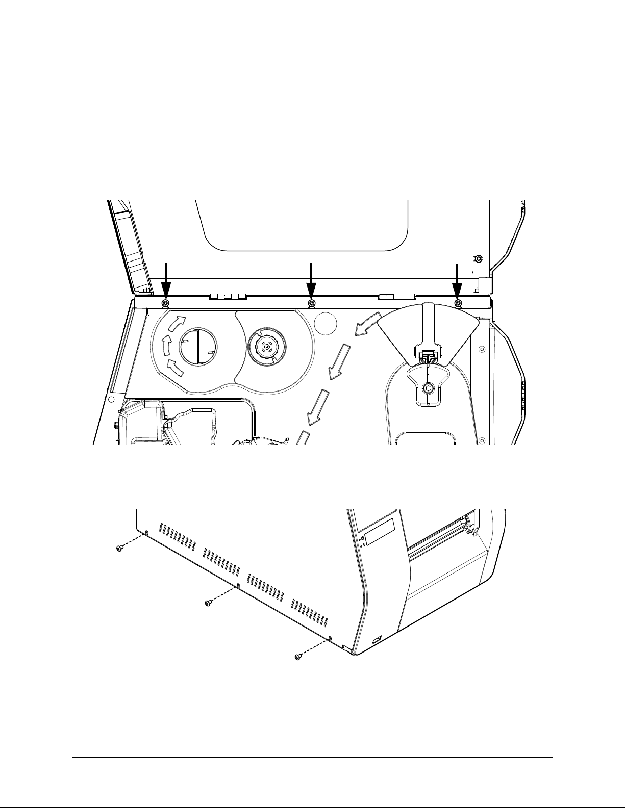
2. Loosen all three (3) 2.5mm hex head screws from the upper cover mount.
Note: For an easier re-installation, loosen but do not remove the screws.
Figure: 2 - 1 Upper Screws
3. Loosen and remove the three (3) 2.5mm hex head screws securing the right side
cover to the printer chassis.
Figure: 2 - 2 Right Side Screws
4. Lift and remove the cover assembly from the printer chassis.
Present Sensor Installation Guide 4
Page 6

Present Sensor Installation | 2
Caution: Exercise caution when removing the cover set assembly and secure it in a safe
position where it will not be damaged.
Figure: 2 - 3 Lift Cover Assembly
5. Remove the center plate plug.
Figure: 2 - 4 Center Plate Plug
5 Present Sensor Installation Guide
Page 7

2 | Present Sensor Installation
6. Press the cable chain bracket into the center plate opening.
Figure: 2 - 5 Cable Chain Bracket
7. Route the cable (SP105337) from the present sensor kit through the opening of the
cable chain bracket and to the main PCB assembly.
8. Connect the connector to junction J4 of the main PCB assembly.
Note: Ensure the cable is safely routed.
9. Connect the cable chain end to the cable chain bracket and press the wires into the
cable chain slot.
Present Sensor Installation Guide 6
Page 8

Note: The cable chain slot should face down.
Cable
slot
Figure: 2 - 6 Cable Chain
Present Sensor Installation | 2
10.Reinstall the cover assembly.
11. If not assembled, seat the present sensor sub-assembly into the support mount and
fasten it to the front panel using the supplied screw.
Note: There are three positions where the present sensor may be mounted. Select the
one that places the present sensor closest to the identifying mark on the media being
used.
7 Present Sensor Installation Guide
Page 9

2 | Present Sensor Installation
Front Panel
Present Sensor
Sub-Assembly
Support Mount
Ribbon Cable Opening
Caution: Ensure the ribbon cable is securely connected to the present sensor sub-
assembly. The cable should be routed upward through the opening in the
support mount.
Figure: 2 - 7 Present Sensor Assembly
Note: The ribbon cable should be routed through the opening.
Present Sensor Installation Guide 8
Page 10

12.Fasten the present sensor assembly to the printer front cover.
Media Cover Open
Front Cover
Ribbon Cable Connector
Extension
Cable Connection
Figure: 2 - 8 Present Sensor Panel Installation
Present Sensor Installation | 2
13.If not assembled, fasten the present sensor PCB assembly to the mounting plate
Figure: 2 - 9 Present Sensor PCB Assembly
using the supplied screws.
9 Present Sensor Installation Guide
Page 11

2 | Present Sensor Installation
Cable Route
14.Connect the ribbon cable from the present sensor to the connector on the PCB
assembly and connect the remaining extension cable connector to the other cable
connection.
Note: Ensure the ribbon cable is seated evenly in the connector before securing the
pressure fitting tab.
15.install the PCB assembly, mounting plate and cover and secure it with the two (2)
screws provided in the kit.
Note: Route the cable out of the bottom corner of the cover.
Figure: 2 - 10 Present Sensor PCB Installation
Present Sensor Installation Guide 10
Page 12

16.Ensure the cable is routed properly through the ferrite.
From Present Sensor PCB Assembly
To the Main PCB Assembly
Figure: 2 - 11 Cable Route
Present Sensor Installation | 2
Note: The cable should be routed through the ferrite as shown.
11 Present Sensor Installation Guide
Page 13

2 | Present Sensor Installation
Ferrite
Connector
Slot
17. Insert the connector through the slot in the cover.
Note: The ferrite should be adhered to the inside of the cover with tape.
Figure: 2 - 12 Present Sensor Ferrite and Cover
Note: The cable should be routed through the ferrite as shown.
18.Secure the cover to the media cover with three nuts.
Note: Ensure the cable going to the present sensor PCB assembly is routed through the
opening on the left rear of the cover.
Present Sensor Installation Guide 12
Page 14

Present Sensor Installation | 2
Note: The remaining nut will be installed on a future step.
Figure: 2 - 13 Cover Installation
19.Securely connect the connectors from the present sensor PCB assembly and the
main PCB assembly.
Figure: 2 - 14 Connectors
13 Present Sensor Installation Guide
Page 15

2 | Present Sensor Installation
20.Insert the connectors through the opening in the box cover and secure the cable
chain to the box cover.
Figure: 2 - 15 Cable Chain Connection
Note: Ensure the cable chain snaps into place over the extrusions.
Present Sensor Installation Guide 14
Page 16

Present Sensor Installation | 2
Cable
Insert this end first
Cable Cover
aution Label
21.Route the left side of the cable cover into the opening in the PCB assembly cover,
route the cable under the cover and secure the cable cover over the box cover with
the remaining nut.
Figure: 2 - 16 Cable Cover Installation
Note: Ensure the cable is positioned correctly under the cable cover to prevent damage.
22.Install the warning label on the upper printhead mechanism.
Figure: 2 - 17 Warning Label
23.Enable the present sensor in the front panel menu.
Note: Refer to the User’s Guide for more information.
15 Present Sensor Installation Guide
 Loading...