

Page 1

Page 2

Page 3

Copyright Information
CG Triumvirate is a trademark of Agfa Corporation.
CG Times based upon Times New Roman under license from the Monotype Corporation.
Windows is a registered trademark of the Microsoft Corporation.
All other brand and product names are trademarks, service marks, registered trademarks, or registered service marks
of their respective companies.
Limitation of Liability
In no event shall Datamax-O'Neil be liable to the purchaser for any indirect, special or consequential damages or lost
profits arising out of or relating to Datamax-O'Neil's products, or the performance or a breach thereof, even if DatamaxO'Neil has been advised of the possibility thereof. Datamax-O'Neil's liability, if any, to the purchaser or to the customer
of the purchaser hereunder shall in no event exceed the total amounts paid to Datamax-O'Neil hereunder by the
purchaser for a defective product.
In no event shall Datamax-O'Neil be liable to the purchaser for any damages resulting from or related to any failure or
delay of Datamax-O'Neil in the delivery or installation of the computer hardware, supplies or software or in the
performance of any services.
Some states do not permit the exclusion of incidental or consequential damages, and in those states the foregoing
limitations may not apply. The warranties here give you specific legal rights, and you may have other legal rights which
vary from state to state.
Firmware (Software) Agreement
The enclosed Firmware (Software) resident in the Printer is owned by Licensor or its suppliers and is licensed for used
only on a single printer in the user's Trade or Business. The User agrees not to, and not to authorize or permit any
other person or party to, duplicate or copy the Firmware or the information contained in the non-volatile or
programmable memory. The firmware (Software) is protected by applicable copyright laws and Licensor retains all
rights not expressly granted. In no event will Licensor or its suppliers be liable for any damages or loss, including
direct, incidental, economic, special, or consequential damages, arising out of the use or inability to use the Firmware
(Software).
Information in this document is subject to change without notice and does not represent a commitment on the part of
Datamax-O'Neil Corporation. No part of this manual may be reproduced or transmitted in any form or by any means,
for any purpose other than the purchaser's personal use, without the expressed written permission of Datamax-O'Neil
Corporation.
Important Safety Instructions
This printer has been carefully designed to provide many years of safe, reliable performance. As with all types of
electrical equipment, however, there are a few basic precautions you should take to avoid hurting yourself or damaging
the equipment:
- Carefully read the provided installation and operating instructions.
- Read and follow all warning instruction labels on the printer.
- Place the printer on a flat, firm, solid surface.
- Make sure all openings on the printer remain unblocked; never insert anything into the openings or ventilation slots.
- Do not place the printer near a heat source.
- Do not use your printer near water, or spill liquid into it.
- Be certain that your power source matches a listed voltage rating for the printer (if unsure, check with your dealer or local utility
company).
- Do not place the power cord where it can be stepped on; and, if the power cord becomes damaged, immediately replace it.
- If service is required, use only qualified trained technicians to repair your printer.
All rights reserved. Copyright © 2015, Datamax-O'Neil
Part Number 88-2362-01, Revision D
Page 4

Page 5
Agency Compliance
This product complies to the following:
CFR 47 Part 15, Class A Digital Device
This device complies with Part 15, Subpart B of the FCC Rules.
Operation is subject to the following two conditions: 1) This device
may not cause harmful interference, and 2) this device must
accept any interference received, including interference that may
cause undesired operation.
This Class A digital apparatus complies with Industry Canada ICS003 Class A requirements.
UL 60950-1, 2nd Edition. Safety of Information Technology
Equipment Including Electrical Business Equipment
CAN/CSA-C22.2 No.60950-1, 2nd Edition. Safety of Information
Technology Equipment Including Electrical Business Equipment
European Council Directive 2004/108/EC “EMC Directive”
EN55022, Emissions, Class A
EN55011, Emissions, Class A (p1120n only)
EN55024, Immunity
EN61000-3-2, Harmonics
EN61000-3-3, Voltage Fluctuations and Flicker
European Council Directive 2006/95/EC “Low Voltage Directive”
IEC 60950-1, 2nd Edition (CB Scheme)
Directive 2011/65/EU RoHS2 [EN5058
Customs Union – Russia, Kazakhstan, Belarus
CISPR 22 Class A Warning
Warning: This is a Class A product. In a domestic environment this
product may cause radio interference in which case the user may
be required to take adequate measures.
1 (2012)]
Page 6
CoC-MEX
ACMA – Australian Communications and Media Authority
EN55022; 2010 +AC:2011 Class A
Certificate of Compliance - Mexico
CoC-Mex-00588-UL; UL 60950-1, 2nd Edition, 2011-12-19
GB4943.1-2011; GB9254-2008 (Class A); GB17625.1-2012
Page 7

Table of Contents
Agency Compliance ....................................................... 5
1. Safety
Warnings and Cautions .................................................. 1
General Safety Information ............................................. 1
2. Overview
About the Printer .............................................................3
p1115 Standard Features ............................................... 6
p1115s Standard Features ............................................. 8
p1120n Standard Features ........................................... 10
p1125 Standard Features ............................................. 12
p1725 Standard Features ............................................. 14
Options .........................................................................16
Unpacking the Printer ...................................................16
Specifications ...............................................................17
3. Connections and Setup
Connections ..................................................................19
Media Loading ..............................................................19
Installing Ribbon ...........................................................32
Configuring Media and Ribbon Settings ....................... 37
Optional Rewinder ........................................................40
Top-of-Form Sensor ..................................................... 42
Removing Ribbon Wrinkle ............................................47
Manual Head Pressure Adjustment (p1115 only) ......... 49
Installing Cutter and Tray ............................................. 51
Upward-Facing Present Sensor ................................... 57
Print Driver Installation .................................................59
4. Menu System
Menu Overview .............................................................61
Layout of the Display ....................................................61
Three Button Panel .......................................................62
Home Screen ................................................................62
Information Button ....................................................... 63
Performance Series User’s Guide
Page 8

Table of Contents
Feed Button .................................................................. 69
Menu ............................................................................70
5. Cleaning and Maintenance
Overview .....................................................................109
Intervals ......................................................................109
Supplies ......................................................................109
Cleaning the Automatic Loading Sensor .................... 109
Cleaning the Top-of-Form Sensor .............................. 109
Cleaning the Paper Low Sensor ................................. 110
Cleaning the Printhead ...............................................110
Cleaning the Cutter ..................................................... 110
6. Maintenance
Safety Overview ......................................................... 111
Tools Needed ............................................................. 111
Replacing the Printhead ............................................. 111
Replacing the Upper Platen Roller ............................. 114
7. Troubleshooting
Errors ..........................................................................119
Warnings ....................................................................120
Troubleshooting .......................................................... 120
Troubleshooting Print Quality ..................................... 123
8. Terms and Definitions
Processing State ........................................................ 125
Printer State ................................................................125
Media Setup ............................................................... 125
Basic ...........................................................................125
Advanced ....................................................................126
Tools ...........................................................................131
Test .............................................................................132
9. Appendix A
Symbol Sets ............................................................... 133
Fonts ...........................................................................134
Barcodes ....................................................................136
Performance Series User’s Guide
Page 9
1 Safety
Warnings and Cautions
The following Warnings and Cautions are used throughout this manual:
Warning: Warnings alert you to possible safety risks.
Caution: Cautions alert you to the potential for equipment damage.
General Safety Information
Caution: This product is intended for indoor use only.
All service procedures should be done by properly trained and qualified service
personnel.
Any on-site assembly required during the installation process must be performed by
properly trained and qualified service personnel.
The product must be connected to a properly grounded and appropriately rated AC
receptacle using the supplied cord set.
Caution: This product contains sensitive electronic components that could be damaged
if exposed to excessive force.
Caution: Use only factory-approved consumables and cleaning kits. Use of any non-
approved supplies could damage the product and void the warranty.
Caution: Do not connect the wireless antenna connection to any outside plant
connection.
Figure: 1 - 1 Caution - Hot
The printhead heats during printing. Do not touch.
1 Performance Series User’s Guide
Page 10

1 | Safety
Performance Series User’s Guide 2
Page 11
2Overview
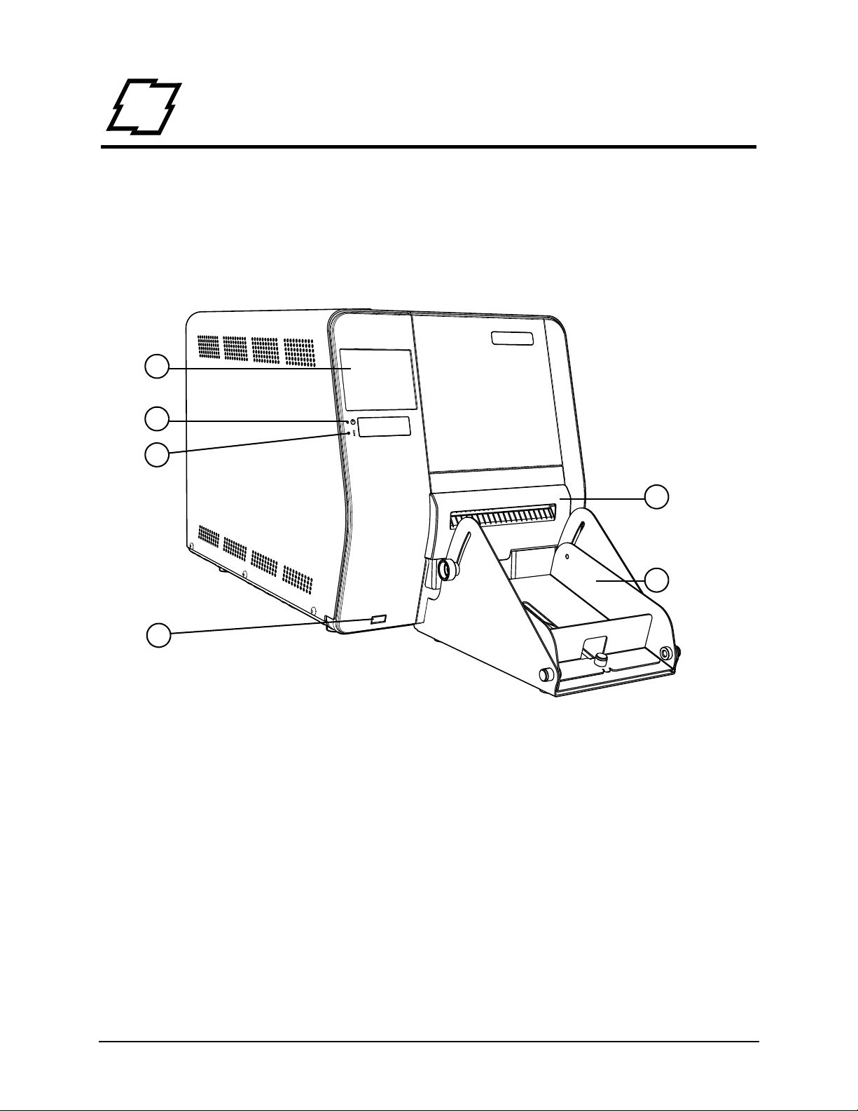
1. Touchscreen Control Panel
2. Power LED
3. Error LED
4. Cutter (Optional)
5. Cutter Tray (Optional)
6. USB Host (Optional)
1
2
3
4
5
6
Some features and options are not available on all models.
About the Printer
Product Tour
The following illustrations show some of the features and available options for the printer.
Figure: 2 - 1 Front View
3 Performance Series User’s Guide
Page 12
2 | Overview
1
2
3
4
5
6
7
8
9
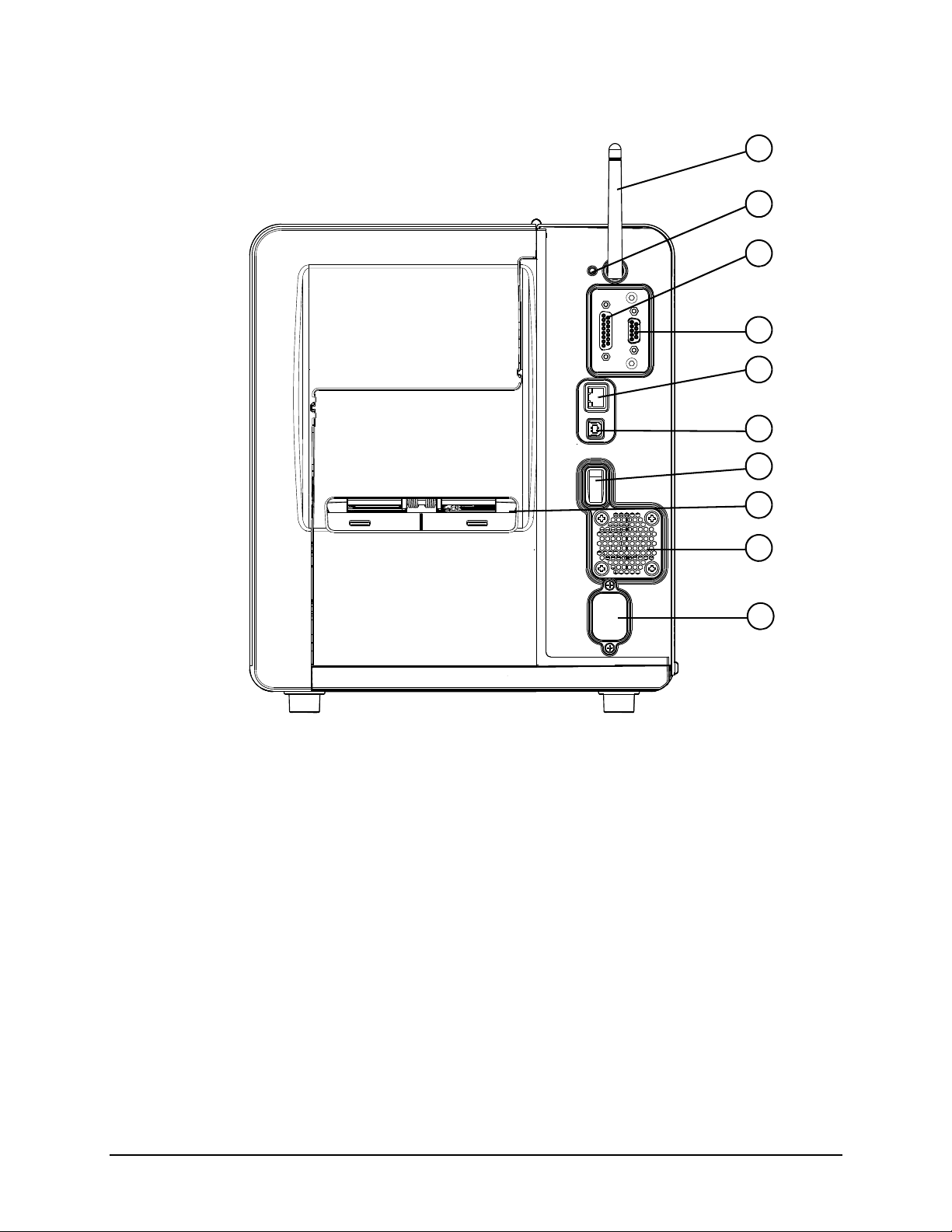
1. Wireless Antenna (Optional)
2. Reset Switch
3. GPIO Port (Optional)
4. Serial Port (Optional)
5. Ethernet/Network Port
6. USB Port
7. Power Switch
8. Fanfold Media Slot
9. Rear Compartment Vent
10. AC Power Inlet
10
Some features and options are not available on all models.
Figure: 2 - 2 Rear View
Performance Series User’s Guide 4
Page 13

Figure: 2 - 3 Media Area
.
1. Head Pressure Adjustment Wheel (p1115 Only)
2. Power Ribbon Transport Assembly (Optional)
3. Ribbon
4. Media
5. Media Hanger
6. Printhead Carriage Assembly
7. Printhead Latch
8. Printhead Latch Lever
9. Rear Fanfold Media Access Slot
10. Platen Carriage Assembly
11. Media Width Guide Adjustment Knob
12. Bouncer
13. Lower Fanfold Media Access Slot
14. Power Media Rewinder Assembly (Optional)
123
4
5
6
7
8
9
10
11
12
13
14
Some features and options are not available on all models.
Overview | 2
5 Performance Series User’s Guide
Page 14
2 | Overview
p1115 Standard Features
The p1115 thermal printer has the following standard features:
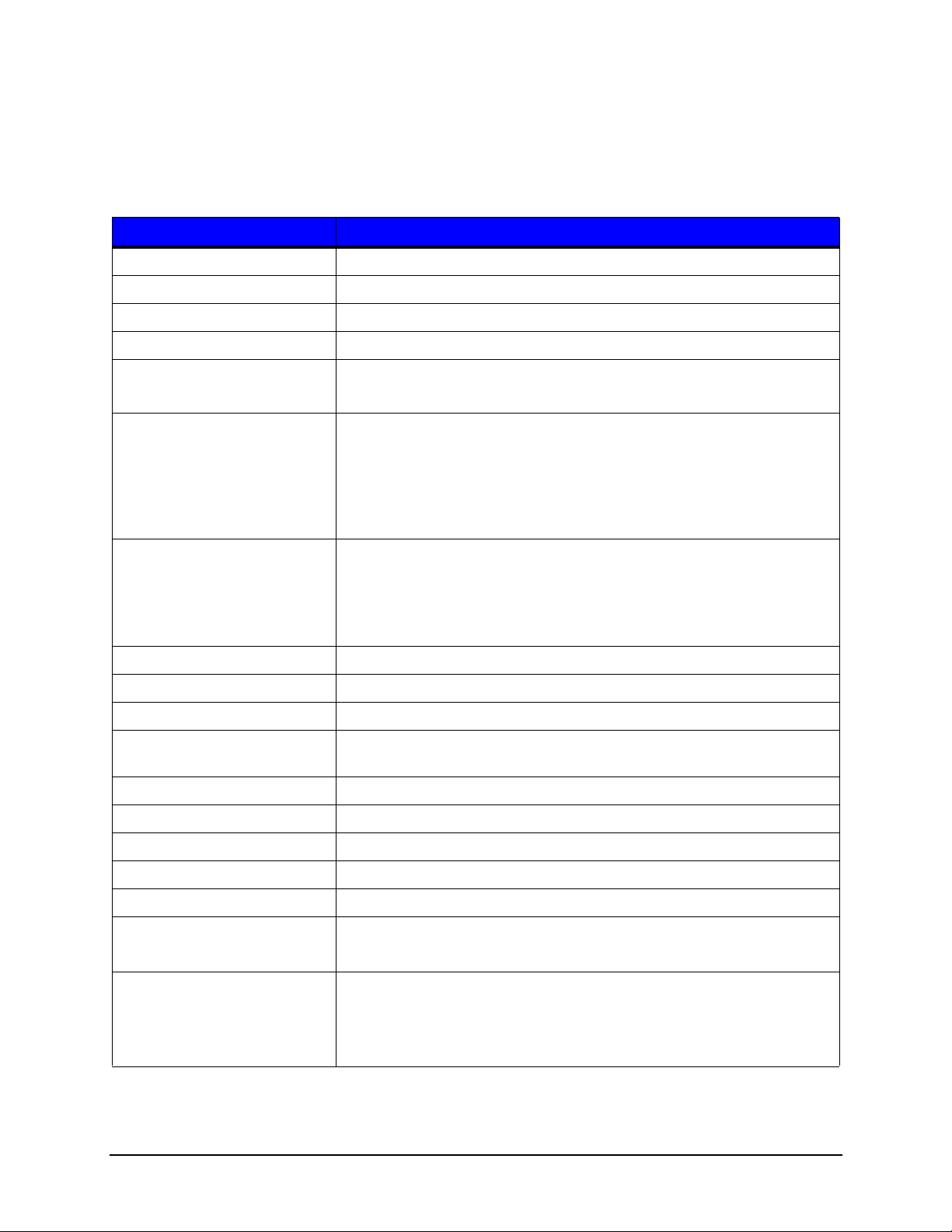
Table 1: p1115 Standard Features
Features Descriptions
Power Supply 110V to 230V
Max Print Speed 6 IPS / 152 mmps
Resolution 300 dpi / 11.8 dpmm
Memory 32 MB Flash (4MB User Space) / 64 MB DDR2 SDRAM
Printer Type • Direct Thermal
• Thermal Transfer (Optional)
Media Supply • Fan fold
• Roll-fed
• Die-cut
• Continuous Labels: perforated or continuous tag/ticket stock (8”
[203mm] roll max diameter.
Double-sided Top-of-Form
Sensor
Tea r Ba r Removable bar for tearing off gapped or continuous media.
Media Back Feed Capable of backing up at least 1.0”.
Control panel LED backlit color QVGA LCD with touchscreen.
Reset Button Inset on the rear of the unit for recovery or the resetting of the screen
LEDs Two LEDs on the front panel for Power and Error.
Power Switch Positioned on the rear of the unit.
Chassis / Media Cover Die cast construction with a clear side window.
Bar Codes See Appendix A
Fonts See Appendix A
Downloadable Font Types • True-Type Scalable
Graphics Full support of PCL5e and GL/2 graphics capability.
Adjustable position for center-biased stock:
• Label Gap
•Notch
• Reflective black mark on the bottom or the top of the form
calibration.
• PCL Bitmap
(Support for various host-based file formats [PCX, BMP] are not part of
the PCL5e standard but are supported and converted by standard
applications)
Performance Series User’s Guide 6
Page 15
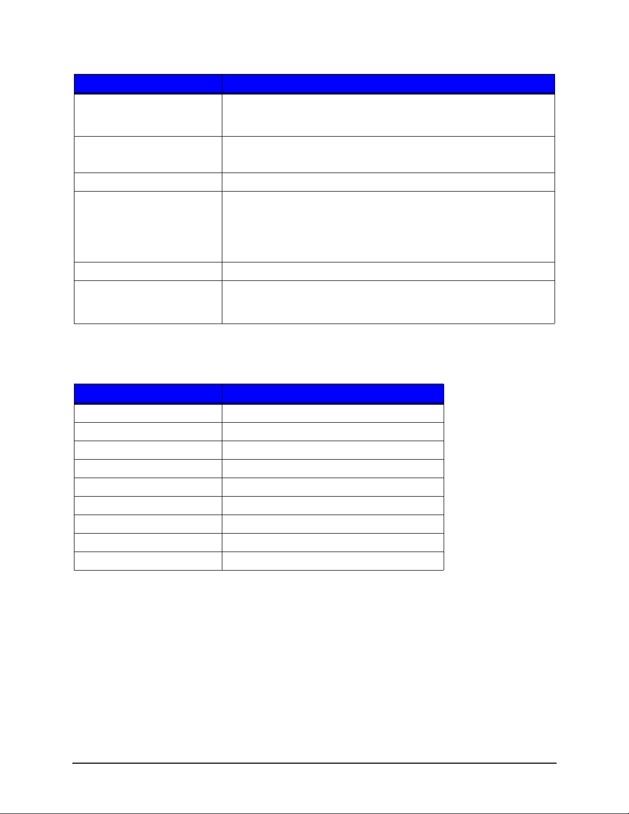
Features Descriptions
Overview | 2
Industry Standard Printer
Language
Interfaces • USB 2.0 Device
Real Time Clock User replaceable battery
Printer Driver Supported
O
perating Systems
Operating Temperature 32°F (0°C) to 104°F (40°C)
Supported Languages in the
isplay
D
HP PJL, HP PCL5e, HP GL/2 and HP XL, printer languages with autolanguage select and extensions for barcode capabilities. Bi-directional
communications capability is also supported.
LAN 10/100
•
• Windows XP
• Windows Vista
• Windows 7
• Windows 8
Front panel languages are configurable via translation files which may
be loaded on the printer. Check with your sales representative for the
most recent list of available translations.
Print Characteristics
Table 2: Print Characteristics
Variable Specifications
Print Resolution 300 dpi (11.8 dpmm)
Max Print Width 4.16” (105.7 mm)
Max Print Speed 6 IPS (152 mmps)
Max Feed Speed 8 IPS (152 mmps)
Max Back-up Speed 5 IPS (127 mmps)
Media Width Range* 1” - 4.65” (25.44 mm - 118.1 mm)
Media Thickness Range* 0.003” - 0.010” (0.076 mm - 0.254 mm)
Ribbon Width Range** 1” - 4.65” (25.44 mm - 118.1 mm)
Print Length 0.25” - 36” (6.35 mm - 915 mm)
*Media wound out.
**Coated side in (CSI) or coated side out (CSO).
7 Performance Series User’s Guide
Page 16

2 | Overview
p1115s Standard Features
The p1115s thermal printer has the following standard features:
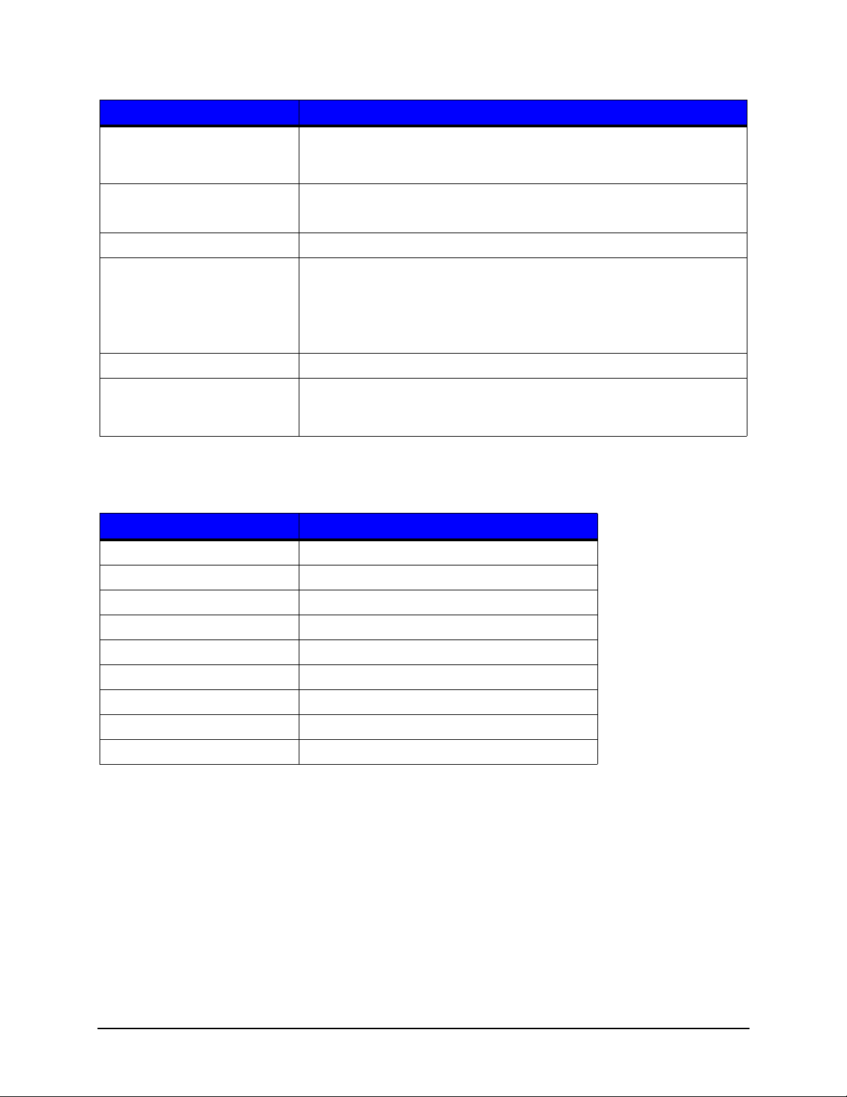
Table 3: p1115s Standard Features
Features Descriptions
Max Print Speed 6 IPS / 152 mmps
Resolution 600 dpi / 23.6 dpmm
Memory 64MB Flash (32MB User Space) / 64MB DDR2 SDRAM
Printer Type • Direct Thermal
• Thermal Transfer (Optional)
Media Supply • Fan fold
• Roll-fed
• Die-cut
• Continuous Labels: perforated or continuous tag/ticket stock (8”
[203 mm] roll max diameter on 1.0”, 1.5” or 3” [25 mm, 38 mm
or 76 mm] core).
Double-sided Top-of-Form
Sensor
Tea r Ba r Removable bar for tearing off gapped or continuous media.
Media Back Feed Capable of backing up at least 1.0”.
Control panel LED backlit color QVGA LCD with touchscreen.
Reset Button Inset on the rear of the unit for recovery or the resetting of the screen
LEDs Two LEDs on the front panel for Power and Error.
Power Switch Positioned on the rear of the unit.
Chassis / Media Cover Die-cast construction with a clear side window.
Bar Codes See Appendix A
Fonts See Appendix A
Downloadable Font Types • True-Type Scalable
Graphics Full support of PCL5e and GL/2 graphics capability.
Adjustable position for center-biased stock:
• Label Gap
•Notch
• Reflective black mark on the bottom or the top of the form
calibration.
• PCL Bitmap
(Support for various host-based file formats [PCX, BMP] are not part of
the PCL5e standard but are supported and converted by standard
applications)
Performance Series User’s Guide 8
Page 17

Features Descriptions
Overview | 2
Industry Standard Printer
Language
Interfaces • USB 2.0 Device
Real Time Clock User replaceable battery
Printer Driver Supported
O
perating Systems
Operating Temperature 32°F (0°C) to 104°F (40°C)
Supported Languages in the
isplay
D
HP PJL, HP PCL5e, HP GL/2 and HP XL, printer languages with autolanguage select and extensions for barcode capabilities. Bi-directional
communications capability is also supported.
LAN 10/100
•
• Windows XP
• Windows Vista
• Windows 7
• Windows 8
Front panel languages are configurable via translation files which may
be loaded on the printer. Check with your sales representative for the
most recent list of available translations.
Print Characteristics
Table 4: Print Characteristics
Variable Specifications
Print Resolution 600 dpi (23.6 dpmm)
Max Print Width 4.16” (105.6 mm)
Max Print Speed 6 IPS (152 mmps)
Max Feed Speed 8 IPS (152 mmps)
Max Back-up Speed 5 IPS (127 mmps)
Media Width Range* 1” - 4.65” (25.44 mm - 118.1 mm)
Media Thickness Range* 0.003” - 0.010” (0.076 mm - 0.254 mm)
Ribbon Width Range** 1” - 4.65” (25.44 mm - 118.1 mm)
Print Length 0.25” - 36” (6.35 mm - 915 mm)
*Media wound out.
**Coated side in (CSI) or coated side out (CSO).
9 Performance Series User’s Guide
Page 18

2 | Overview
p1120n Standard Features
The p1120n thermal printer has the following standard features:
Table 5: p1120n Standard Features
Features Descriptions
Max Print Speed 8 IPS / 203 mmps
Resolution 300 dpi / 11.8 dpmm
Memory 32MB Flash (4MB User Space) / 64MB DDR2 SDRAM
Printer Type • Direct Thermal
• Thermal Transfer (Optional)
Media Supply • Fan fold
• Roll-fed
• Die-cut
• Continuous Labels: perforated or continuous tag/ticket stock (8”
[203 mm] roll max diameter on 1.0”, 1.5” or 3” [25 mm, 38 mm
or 76 mm] core).
Double-sided Top-of-Form
Sensor
Tea r Ba r Removable bar for tearing off gapped or continuous media.
Media Back Feed Capable of backing up at least 1.0” (for near edge printhead).
Control panel LED backlit color QVGA LCD with touchscreen.
Reset Button Inset on the rear of the unit for recovery or the resetting of the screen
LEDs Two LEDs on the front panel for Power and Error.
Power Switch Positioned on the rear of the unit.
Chassis / Media Cover Die-cast construction with a clear side window.
Bar Codes See Appendix A
Fonts See Appendix A
Downloadable Font Types • True-Type Scalable
Graphics Full support of PCL5e and GL/2 graphics capability.
Adjustable position for center-biased stock:
• Label Gap
•Notch
• Reflective black mark on the bottom or the top of the form
calibration.
• PCL Bitmap
(Support for various host-based file formats [PCX, BMP] are not part of
the PCL5e standard but are supported and converted by standard
applications)
Performance Series User’s Guide 10
Page 19
Features Descriptions
Overview | 2
Industry Standard Printer
Language
Interfaces • USB 2.0 Device
Real Time Clock User replaceable battery
Printer Driver Supported
O
perating Systems
Operating Temperature 32°F (0°C) to 104°F (40°C)
Supported Languages in the
isplay
D
HP PJL, HP PCL5e, HP GL/2 and HP XL, printer languages with autolanguage select and extensions for barcode capabilities. Bi-directional
communications capability is also supported.
LAN 10/100
•
• Windows XP
• Windows Vista
• Windows 7
• Windows 8
Front panel languages are configurable via translation files which may
be loaded on the printer. Check with your sales representative for the
most recent list of available translations.
Print Characteristics
Table 6: Print Characteristics
4” Near Edge
Print Resolution 300 dpi (11.8 dpmm)
Max Print Width 4.27” (108.5 mm)
Max Print Speed 8 IPS (203 mmps)
Max Feed Speed 10 IPS (254 mmps)
Max Back-up Speed 5 IPS (127 mmps)
Media Width Range* 1” - 4.65” (25.44 mm - 118.1 mm)
Media Thickness Range* 0.003” - 0.020” (0.076 mm - 0.508 mm)
Ribbon Width Range** 1” - 4.65” (25.44 mm - 118.1 mm)
Print Length 0.2” - 99” (5.08 mm - 2475.6 mm)
*Media wound out.
**Coated side in (CSI) or coated side out (CSO).
11 Performance Series User’s Guide
Page 20
2 | Overview
p1125 Standard Features
The p1125 thermal printer has the following standard features:
Table 7: p1125 Standard Features
Features Descriptions
Max Print Speed 10 IPS / 254 mmps
Resolution 300 dpi / 11.8 dpmm
Memory 32 MB Flash (4 MB User Space) / 64 MB DDR2 SDRAM
Printer Type • Direct Thermal
• Thermal Transfer (Optional)
Media Supply • Fan fold
• Roll-fed
• Die-cut
• Continuous Labels: perforated or continuous tag/ticket stock (8”
[203 mm] roll max diameter on 1.0”, 1.5” or 3” [25 mm, 38 mm
or 76 mm] core).
Double-sided Top-of-Form
Sensor
Tea r Ba r Removable bar for tearing off gapped or continuous media.
Media Back Feed Capable of backing up at least 1.0”.
Control panel LED backlit color QVGA LCD with touchscreen.
Reset Button Inset on the rear of the unit for recovery or the resetting of the screen
LEDs Two LEDs on the front panel for Power and Error.
Power Switch Positioned on the rear of the unit.
Chassis / Media Cover Die-cast construction with a clear side window.
Bar Codes See Appendix A
Fonts See Appendix A
Downloadable Font Types • True-Type Scalable
Graphics Full support of PCL5e and GL/2 graphics capability.
Adjustable position for center-biased stock:
• Label Gap
•Notch
• Reflective black mark on the bottom or the top of the form
calibration.
• PCL Bitmap
(Support for various host-based file formats [PCX, BMP] are not part of
the PCL5e standard but are supported and converted by standard
applications)
Performance Series User’s Guide 12
Page 21

Features Descriptions
Overview | 2
Industry Standard Printer
Language
Interfaces • USB 2.0 Device
Real Time Clock User replaceable battery
Printer Driver Supported
O
perating Systems
Operating Temperature 32°F (0°C) to 104°F (40°C)
Supported Languages in the
isplay
D
HP PJL, HP PCL5e, HP GL/2 and HP XL, printer languages with autolanguage select and extensions for barcode capabilities. Bi-directional
communications capability is also supported.
LAN 10/100
•
• Windows XP
• Windows Vista
• Windows 7
• Windows 8
Front panel languages are configurable via translation files which may
be loaded on the printer. Check with your sales representative for the
most recent list of available translations.
Print Characteristics
Table 8: Print Characteristics
Variable Specifications
Print Resolution 300 dpi (11.8 dpmm)
Max Print Width 4.27” (108.5 mm)
Max Print Speed 10 IPS (254 mmps)
Max Feed Speed 12 IPS (254 mmps)
Max Back-up Speed 5 IPS (127 mmps)
Media Width Range* 1” - 4.65” (25.44 mm - 118.1 mm)
Media Thickness Range* 0.003” - 0.010” (0.076 mm - 0.254 mm)
Ribbon Width Range** 1” - 4.65” (25.44 mm - 118.1 mm)
Print Length 0.10” - 99” (5.08 mm - 2475.6 mm)
*Media wound out.
**Coated side in (CSI) or coated side out (CSO).
13 Performance Series User’s Guide
Page 22

2 | Overview
p1725 Standard Features
The p1725 thermal printer has the following standard features:
Table 9: p1725 Standard Features
Features Descriptions
Max Print Speed 10 IPS / 254 mmps
Resolution 300 dpi / 11.8 dpmm
Memory 64 MB Flash (32 MB User Space) / 64 MB DDR2 SDRAM
Printer Type • Direct Thermal
• Thermal Transfer (Optional)
Media Supply • Fan fold
• Roll-fed
• Die-cut
• Continuous Labels: perforated or continuous tag/ticket stock (8”
[203 mm] roll max diameter on 1.0”, 1.5” or 3” [25 mm, 38 mm
or 76 mm] core).
Double-sided Top-of-Form
Sensor
Tea r Ba r Removable bar for tearing off gapped or continuous media.
Media Back Feed Capable of backing up at least 1.0”.
Control panel LED backlit color QVGA LCD with touchscreen.
Reset Button Inset on the rear of the unit for recovery or the resetting of the screen
LEDs Two LEDs on the front panel for Power and Error.
Power Switch Positioned on the rear of the unit.
Chassis / Media Cover Die-cast construction with a clear side window.
Bar Codes See Appendix A
Fonts See Appendix A
Downloadable Font Types • True-Type Scalable
Adjustable position for center-biased stock:
• Label Gap
•Notch
• Reflective black mark on the bottom or the top of the form
calibration.
• Intellifont Scalable
• PCL Bitmap
Graphics Full support of PCL5e and GL/2 graphics capability.
(Support for various host-based file formats [PCX, BMP] are not part of
the PCL5e standard but are supported and converted by standard
applications)
Performance Series User’s Guide 14
Page 23

Features Descriptions
Overview | 2
Industry Standard Printer
Language
Interfaces • USB 2.0 Device
Real Time Clock User replaceable battery
Printer Driver Supported
O
perating Systems
Operating Temperature 32°F (0°C) to 104°F (40°C)
Supported Languages in the
isplay
D
HP PJL, HP PCL5e, HP GL/2 and HP XL, printer languages with autolanguage select and extensions for barcode capabilities. Bi-directional
communications capability is also supported.
LAN 10/100
•
• Windows XP
• Windows Vista
• Windows 7
• Windows 8
Front panel languages are configurable via translation files which may
be loaded on the printer. Check with your sales representative for the
most recent list of available translations.
Print Characteristics
Table 10: Print Characteristics
Variable Specifications
Print Resolution 300 dpi (11.8 dpmm)
Max Print Width 6.83” (173.5 mm)
Max Print Speed 10 IPS (254 mmps)
Max Feed Speed 12 IPS (254 mmps)
Max Back-up Speed 5 IPS (127 mmps)
Media Width Range* 2” - 7.1” (50.8 mm - 180.3 mm)
Media Thickness Range* 0.003” - 0.010” (0.076 mm - 0.254 mm)
Ribbon Width Range** 2” - 7.1” (50.8 mm - 180.3 mm)
Print Length 0.25” - 36” (6.35 mm - 915 mm)
*Media wound out.
**Coated side in (CSI) or coated side out (CSO).
15 Performance Series User’s Guide
Page 24

2 | Overview
Options
The following options are available:
• Thermal Transfer (Ribbon)
• Internal Power Rewind with Batch Rewind
• Media Present Sensor (Future option for the p1725)
• Peel and Present (Future option for the p1725)
• Media Cutter (Future option for the p1725)
• Media Cutter Tray (Future option for the p1725)
• Applicator Port (General Purpose I/O) and Serial Port (RS-232C)
• Wireless Module (not an available option for the p1115)
• USB Host Port (not an available option for the p1115)
• Audio Indicator (not an available option for the p1115)
• Media Hub with 1.0”,1.5” or 3” media hub adapters (not an available option for the
p1725)
• Non-US Power Cords
Unpacking the Printer
Upon receiving the printer, verify the box is undamaged. Carefully unpack the printer
from its packaging and visually check for any physical damage that may have occurred
during shipment.
Checking the Contents
The contents may vary depending on your configuration. It is recommended that all
packaging materials be saved if the printer is to be shipped again. If the packaging
material is discarded, new packaging material may be available from your reseller.
• Printer
• Power Cord
• Driver CD
• Product documentation not included on the CD
• Accessories/Options
Additional items that may be required include the following:
• All applicable communication cables
•Media
• Ribbon
Performance Series User’s Guide 16
Page 25
Specifications
Dimensions and Weight
Table 11: Dimensions and Specifications (p1115, p1115s, p1120n, p1125)
Height Width Depth Weight
11.9 in (30.3 cm) 10.8 in (27.4 cm) 18.7 in (47.5 cm) 41 lbs. (19 kg)
Table 12: Dimensions and Specifications (p1725)
Height Width Depth Weight
11.9 in (30.3 cm) 13.4 in (34 cm) 18.7 in (47.5 cm) 52 lbs. (24 kg)
Environmental
Table 13: Temperatu res
Temperature Humidity
Overview | 2
Operating 32°F to 104°F (0°C to 40°C) <=20% to 80%
Storage -4°F to 140°F (-20°C to 60°C) <=35%
Print Driver Requirements
Table 14: Print Driver Minimum System Requirements
Minimum System Requirements
Processor / Speed 500 MHz processor
RAM 512 MB
Hard Drive Space 6 MB
Supported Operating Systems Windows XP - x86 & x64
Windows Vista - x86 & x64
Windows 7 - x86 & x64
Windows 8
Configuration Utility
Table 15: Configuration Utility Minimum System Requirements
Minimum System Requirements
Processor / Speed 500 MHz processor
17 Performance Series User’s Guide
Page 26
2 | Overview
Minimum System Requirements
Supported Operating Systems Windows XP - x86 & x64
Windows Vista - x86 & x64
Windows 7 - x86 & x64
Windows 8
RAM 256 MB
Hard Drive Space 5 MB
Minimum Screen Resolution 800 x 600
.NET Framework 2.0
Performance Series User’s Guide 18
Page 27

3 Connections and Setup
Connections
Power
To connect the printer to a viable power source, please follow the steps below.
Caution: Ensure the printer power switch is off before connecting the AC power and
data/network connectivity cables to the printer.
Caution: Adhere to all environmental requirements when installing and using the printer.
Use of the product in an unsuitable environment may affect print quality and the
durability of the printer and may void the manufacturer’s warranty.
1. Place the printer on a suitable level surface capable of securely supporting 60lbs.
2. Connect the AC power cord to the AC power inlet on the back of the printer.
3. Connect the AC power cord to AC utility power.
Data
Printer data connectivity can be accomplished by the following standard or optional
interfaces:
•USB
• Ethernet/Network
• Serial (Optional)
• GPIO (Optional)
• Wireless (Optional)
Connect the appropriate interface cables for your network configuration.
Media Loading
The printer is designed to print on media that is center-aligned on the media hanger.
There are two different media mounts available for most models.
The standard self-centering media hanger synchronizes the adjustment to facilitate the
centering of the media. The optional self-centering media hub* allows for the use of 1”,
1.5” and 3” roll cores.(*Not available for all printer models.)
Please consult your sales representative to obtain the appropriate media.
Note: The printer should be connected to AC power and running during media loading.
19 Performance Series User’s Guide
Page 28
3 | Connections and Setup
1. Inside media adjustment lever
2. Paper low sensor (Optional)
3. Self-centering media hanger
4. Outside media adjustment lever
5. Media adjuster knob
1
2
3
4
5
Media Hanger Overview
Figure: 3 - 1 Self-Centering Media Hanger
Media Specifications
Media core size:
• 3” (76.199 mm)
Media roll diameter:
• Maximum -- 8”
Performance Series User’s Guide 20
Page 29
Connections and Setup | 3
Media roll width:
• Please refer to the model feature charts in the Overview section.
Media thickness:
• 0.003” to 0.01” (the p1120n can accept media thickness of up to 0.020”)
Media dimensions:
• Please refer to the model feature charts in the Overview section.
Note: Ensure there is no tape or adhesive residue on the media roll.
Installing Media on the Media Hanger
1. Open the media cover.
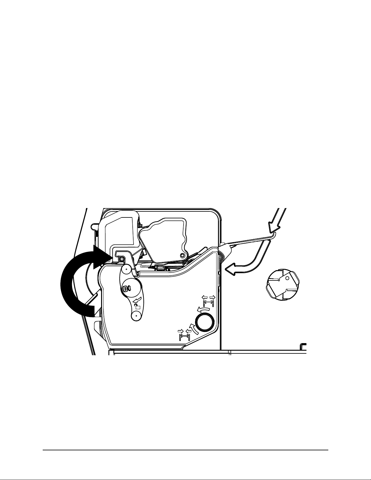
2. Unlock the printhead mechanism by turning the printhead latch lever clockwise about 190°.
Note: Do not unlatch the printhead mechanism.
Figure: 3 - 2 Unlock the Printhead Mechanism
21 Performance Series User’s Guide
Page 30
3 | Connections and Setup
3. Center the media adjuster knob and pull it to widen the gap between the two media adjustment levers.
Figure: 3 - 3 Self-Centering Media Hanger from Top
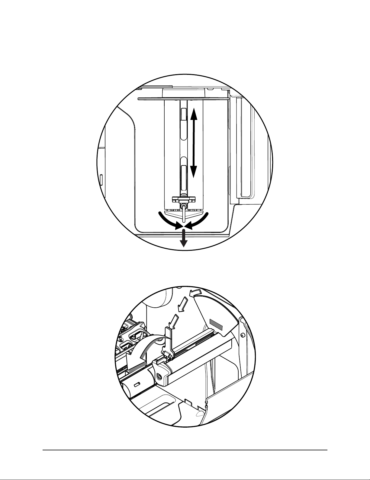
4. Rotate the outside media adjustment lever downward.
Figure: 3 - 4 Outside Media Adjustment Lever
Performance Series User’s Guide 22
Page 31

Connections and Setup | 3
5. Gently route the media core over the outside media adjustment lever onto the media hanger.
Caution: Be careful not to damage the outside media adjustment lever.
Figure: 3 - 5 Media Installation
6. Rotate the outside media adjustment lever upward.
Figure: 3 - 6 Outside Media Adjustment Lever
7. Slide the media adjuster knob inward to center the media roll on the media hanger.
23 Performance Series User’s Guide
Page 32

3 | Connections and Setup
Media Guides
Note: Ensure the media roll turns freely. There should be 0.8 mm to 1.5 mm clearance
between the media adjustment levers and the media roll.
8. Rotate the media guide adjustment knob counter clockwise to widen the guides until they are set slightly wider than the width of the media.
Figure: 3 - 7 Media Guide Adjustment Knob
9. Route the media under the bouncer and into the media guides.
Figure: 3 - 8 Media Guides
Performance Series User’s Guide 24
Page 33

Connections and Setup | 3
Pinch Roller Knob
Pinch Roller
10.Press the pinch roller knob and slide the media 0.25 inches beyond the pinch roller.
Figure: 3 - 9 Pinch Roller
11. Rotate the media guide adjustment knob clockwise to tighten the guides.
Note: Ensure the guides are neither too tight nor too loose on the media or print quality
will be affected.
Figure: 3 - 10 Tighten Media Guide Adjustment Knob
25 Performance Series User’s Guide
Page 34

3 | Connections and Setup
12.Rotate the latch lever counter-clockwise until the printhead mechanism is locked.
Figure: 3 - 11 Lock the Printhead Mechanism
Note: If the media has been installed properly and read by the autoloading sensor, it
should automatically feed under the printhead once the printhead carriage assembly has
been latched and locked. If the media does not automatically load, unlatch the printhead
assembly and manually feed the media under the printhead. Upon locking the printhead,
it would be beneficial to both feed the media by selecting the Feed button on the main
menu to properly set the next label and perform a Paper Calibration.
13.Set the Top-of-Form sensor
Note: Refer to the section called “Top-of-Form Sensor.” Setting the top-of-form sensor to
read specific media characteristics is done in the control panel.
Performance Series User’s Guide 26
Page 35

Optional Media Hub Overview
1
2
3
4
5
1. Media hub adjustment channels
2. Media hub adjustment lever
3. Hub adjustment slots
4. Media hub
5. Core holders
Figure: 3 - 12 Media Hub Layout from Top
Connections and Setup | 3
Media Specifications
Media core size:
• 3” (76.199 mm) standard
• 1” (25.4 mm) optional
• 1.5” (38.099 mm) optional
Media roll diameter:
• Maximum - 8”
Media roll width:
• Maximum - 4.65”
Media thickness:
• 0.003” to 0.01” (the p1120n can accept media thickness of up to 0.020”)
27 Performance Series User’s Guide
Page 36

3 | Connections and Setup
Media Hub
Adjustment
Lever
Hub
Handle
Media dimensions:
• Minimum specifications - 0.5” H x 1” W
Note: Ensure there is no tape or adhesive residue on the media roll.
Installing Media on the Media Hub
1. Open the media cover.
2. Press the media hub adjustment lever and pull the media hanger outward using the handle.
Figure: 3 - 13 Media installation
3. Hold the media hub adjustment lever and place the media core on the core holders.
Performance Series User’s Guide 28
Page 37

Connections and Setup | 3
Media Guide
Bouncer
Media
Guide
4. Slide the media hub inward using the handle and release the hub adjustment lever once the media is supported.
Figure: 3 - 14 Media Installation
5. Route the media under the bouncer and into the media guides.
Figure: 3 - 15 Media Guide
29 Performance Series User’s Guide
Page 38

3 | Connections and Setup
Pinch Roller Knob
Pinch Roller
6. Press the pinch roller knob and slide the media 0.25 inches beyond the pinch roller.
Figure: 3 - 16 Pinch Roller View from Top
7. While pressing the pinch roller knob, rotate the media guide adjustment wheel until the media guide touches the media on both sides.
Caution: Ensure the media guides are neither too tight nor too loose or print quality will
be affected and feed issues may develop.
Performance Series User’s Guide 30
Page 39

Connections and Setup | 3
Note: To loosen the media guides, rotate the media guide adjustment wheel counter-
clockwise. To tighten, rotate the adjustment wheel clockwise.
Figure: 3 - 17 Media Guide Adjustment Wheel
Note: The factory default media width is set to 4 inches.
31 Performance Series User’s Guide
Page 40

3 | Connections and Setup
Installing Ribbon
For thermal transfer printing, ribbon must be installed. The ribbon should be slightly
wider than the print media being used to ensure proper coverage.
1. Open the media cover.
2. Rotate the printhead latch lever clockwise to unlock and raise the printhead carriage assembly.
Figure: 3 - 18 Printhead Latch Lever
3. Slide the ribbon core over the ribbon supply hub until the core is centered on the hub.
Performance Series User’s Guide 32
Page 41

Note: Only use ribbon with a 1” diameter core.
Ribbon Supply Hub
Figure: 3 - 19 Install Ribbon
Connections and Setup | 3
4. Route the ribbon between the ribbon cam roller and the green top-of-form adjustment lever.
Note: The printer supports both coated side in (CSI) and coated side out (CSO). Ensure
the ink side faces the media.
Note: See the Menu section for information on setting the printer to run inside or outside
ink.
33 Performance Series User’s Guide
Page 42

3 | Connections and Setup
Cam Roller
Top-of-Form
Sensor Adjustment
Inside Ink Shown
Lever
Caution: Do not route the ribbon under the top-of-form sensor.
Figure: 3 - 20 Route Ribbon (Inside ink ribbon is shown)
Performance Series User’s Guide 34
Page 43

Connections and Setup | 3
5. Route the ribbon under the printhead, over the ribbon shield and clockwise around the ribbon rewinder hub.
Figure: 3 - 21 Route to Ribbon Rewinder Hub
Note: Roll the ribbon around the ribbon rewinder hub at least five (5) times to ensure it
will stay in position.
6. Ensure the thermal transfer option is selected in the control panel.
7. Set the thermal transfer option to CSI or CSO depending on the ribbon type.
Note: See the menu section for more information about the printer settings.
35 Performance Series User’s Guide
Page 44

3 | Connections and Setup
8. Rotate the printhead carriage assembly counter-clockwise until it latches.
Figure: 3 - 22 Latch the Printhead Carriage Assembly
9. Rotate the printhead latch lever counter-clockwise to lock the printhead carriage.
Note: Ensure the printhead latch lever has locked the printhead mechanism before
printing or the printer will enter a no-print condition.
Note: When removing the ribbon from the ribbon rewinder hub, grasp the center of the
ribbon, squeeze tightly and pull outward away from the rewinder hub. The rewinder hub
will collapse slightly allowing the used ribbon to slide off.
Performance Series User’s Guide 36
Page 45

Connections and Setup | 3
Configuring Media and Ribbon Settings
Once the media and ribbon have been loaded, the print parameters should be set to
match the type of media and ribbon being used. This will ensure optimal print quality.
Once set, the parameters will not need to be set again unless the media or ribbon types
are changed.
Using Media and Ribbon IDs
Media and ribbons supplied by Datamax-O’Neil and other vendors may have up to an
eight (8) digit media ID and ribbon ID assigned. Additional codes may be created in the
Utility menu and then selected from Media menu via the printer’s front panel. All relevant
print parameters will be automatically configured.
1. Select Menu > Basic > Media > Media ID.
2. Using the up and down arrows, select the appropriate Paper ID.
3. To select the Ribbon ID, navigate to tab 2 and use the scroll arrows to highlight and select the appropriate Ribbon ID.
4. Select the Home button.
5. After selecting the Home button, select the green Accept button to again confirm your selection or the red Reject button to cancel the changes.
Note: Although using media and ribbon IDs usually produce very good results, minor
adjustments may be required. Refer to the section titled Adjusting Media and Ribbon
Settings.
Selecting Media and Ribbon Types
If media and ribbon IDs are not known, the media and ribbon types may be selected
manually.
1. Select Menu > Basic > Media > Select Type.
2. Using the up and down arrows, select your paper type.
Note: If the paper type is not known, either select Coated Direct Thermal for direct
thermal printing or select Coated Thermal Transfer for printing with a ribbon.
3. Tab to the Ribbon screen.
4. Using the up and down arrow, select your ribbon type.
Note: If the ribbon type is not known, select Wax to start. This selection can always be
changed if required.
5. Tab to the Settings screen.
37 Performance Series User’s Guide
Page 46

3 | Connections and Setup
6. Select the Paper Sensor Type button until your paper type appears. The options
are as follows:
•Gap
• Mark on Top
• Mark on Bottom
•Notch
• Continuous
Note: For more information, refer to the section “Top-of-Form Sensor.”
7. Select the Paper Sensor Side button until the correct option appears. The options
are as follows:
•Outside
• Inside
Note: For more information, refer to the section “Top-of-Form Sensor.”
8. Select the Ribbon Mode button until the correct option appears. The options are as
follows:
•None
• Coated In (CSI)
• Coated Out (CSO)
Note: For more information, refer to the section “Top-of-Form Sensor.”
Note: CSI ribbon (shiny side facing outward) should be installed where the ribbon
unwinds in a counter-clockwise direction. CSO ribbon (dull side facing outward) should
be installed where the ribbon unwinds in a clockwise direction. If these settings do not
match the ribbon type being used, the ribbon supply hub will turn in the wrong direction.
Setting the Media and Ribbon Parameters Manually (Advanced)
There are times when all print parameters must be set manually. This can happen when
a new or specialized media or ribbon are being used.
Note: Some values may be grayed-out, meaning they are automatically set by default.
To change these values, select the Auto button next to the value field and then select the
green Accept button to confirm your choice to change to manual mode.
Note: Please see the Menu section for more information.
1. Select Menu > Advanced > Media.
2. Select the Paper Sensor Type field until the correct paper type appears. The
options are as follows:
•Gap
Performance Series User’s Guide 38
Page 47

Connections and Setup | 3
• Mark on Top
• Mark on Bottom
•Notch
• Continuous
3. Select the Paper Sensor Side field until the correct option appears. The options
are as follows:
•Outside
• Inside
4. Select the Ribbon Mode field until the correct option appears. The options are as
follows:
• None - for direct thermal printing
• Coated In - for thermal transfer printing
• Coated Out - for thermal transfer printing
5. Tab to the next screen and enter values for Heat and Heat Balance.
6. Tab to the next screen and enter values for Head Pressure and Rewinder Tension.
7. Tab to the next screen and enter values for Ribbon Tension Front and Ribbon Tension Rear.
8. Tab to the next screen and enter values for Ribbon Low Diameter, Gap/Mark Offset and Gap/Mark Noise.
9. If media levels are to be tracked, tab to the next screen and enter values for Ribbon Length, Form Length and Number of Forms. These parameters are used for media tracking when Paper Change Warning is enabled.
10.Select the Home button and select the green Accept button to confirm the settings.
Load a Saved Media File
For media and ribbon settings that are frequently used, media setup files can be saved to
the printer’s internal memory for easy access. For more information on saving the user
setup files, refer to the section titled Setups from the Tools > User Files menu section.
To select an internally saved media setup file, perform the following steps:
1. Select Menu > Basic > Media > User Media.
2. Using the up and down arrows, select the appropriate Internal Media Setup File.
3. Select the green Accept button and confirm the settings.
39 Performance Series User’s Guide
Page 48

3 | Connections and Setup
Counter Clockwise
Clockwise
Metal Clasp
Optional Rewinder
The rewinder is designed to rewind in either direction but the direction must be set
through the menu.
Note: Either the peel plate or the rewinder plate must be installed.
Installation of Media
1. Route the media through the platen carriage assembly.
Note: Follow the instructions for the installed media hanger.
2. Route the media under the platen carriage and around the rewinder shaft.
3. Remove the metal clasp and wind the media around the rewinder shaft in the desired direction.
Figure: 3 - 23 Rewinder
4. Insert the edge of the media into one of the two grooves on the rewinder shaft.
Performance Series User’s Guide 40
Page 49

Connections and Setup | 3
Note: For thicker labels, remove the label from the backing and insert the backing into
the groove.
Figure: 3 - 24 Media Rewinder
Note: Be sure to center align the paper on the rewinder shaft. Otherwise, the paper will
not rewind tightly.
5. Reinstall the metal clasp into the grooves.
Perform the following steps to set the rewinder direction:
1. Select Menu > Basic > Printer Mode.
2. Select the rewinder direction.
Note: Upon exiting the utility, a prompt will ask the user to accept the changes or reject
them.
Note: If the rewinder is enabled and the Auto Present Distance is set, then the printer
present distance will be set to zero (0) to avoid unnecessary backing up.
41 Performance Series User’s Guide
Page 50

3 | Connections and Setup
Note: If the rewinder is enabled, the Auto Present Distance set, and the printer in
Prompt or Applicator mode, then the actual printer present distance will be set to work
with the peel mechanism.
Top-of-Form Sensor
This printer is designed to use several types of media. The top-of-form sensor can read
media characteristics from the center to the left inside edge (viewing from the front of the
printer). Setting the top-of-form sensor to read specific media characteristics is done in
the control panel.
Media Types Supported
There are five paper types that are supported. These include gap, mark on top, mark on
bottom, notch and continuous.
The following are illustrations of the types of supported media but not every supported
media is illustrated. Please contact your reseller for assistance in selecting the
appropriate media for the printer.
Figure: 3 - 25 Gap Example
Performance Series User’s Guide 42
Page 51

Figure: 3 - 26 Notch Example
Note: The use of Notch paper disables the Out of Paper warning.
Connections and Setup | 3
43 Performance Series User’s Guide
Page 52

3 | Connections and Setup
Figure: 3 - 27 Mark on Top Example
Figure: 3 - 28 Mark on Bottom Example
Figure: 3 - 29 None
Note: For continuous paper, excessive vertical adjustment may push the print into the
next label. This mode will create labels with a 1/8” gap between them.
Performance Series User’s Guide 44
Page 53

Connections and Setup | 3
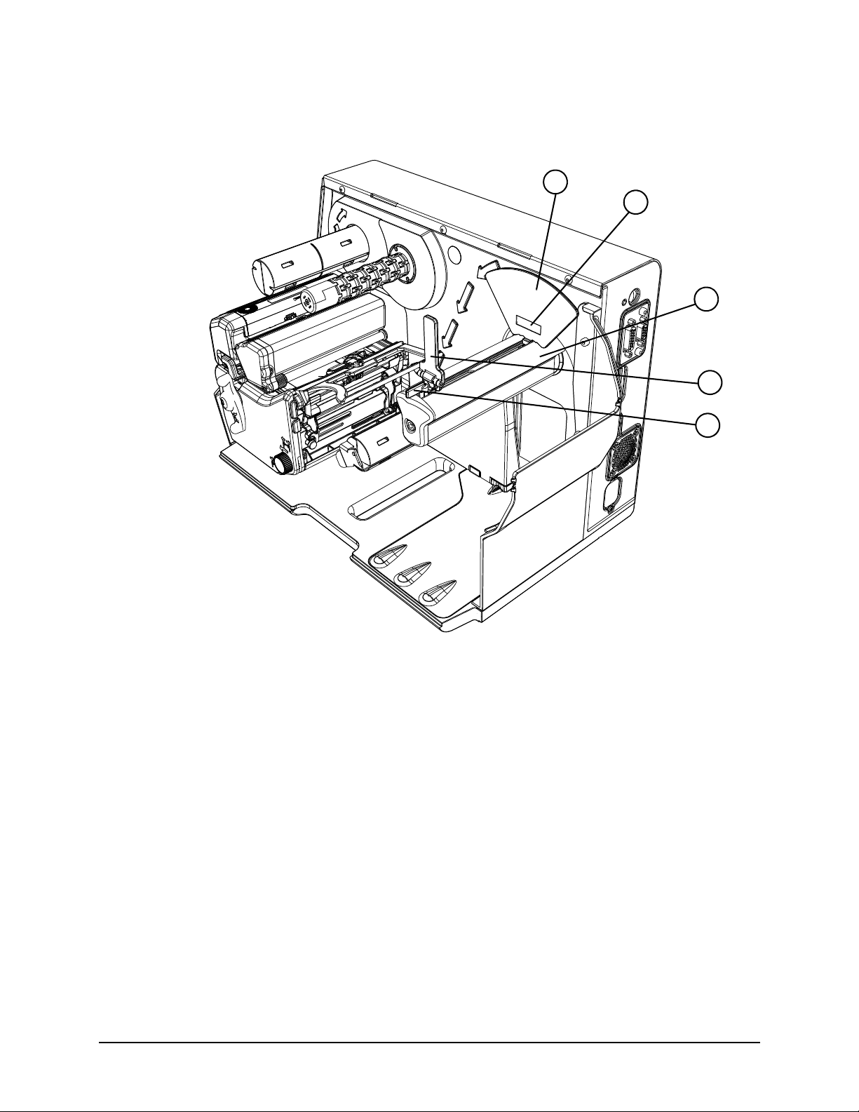
Mark
Inside Sensor Pod
Outside Sensor Pod
Lever
Top-of-Form
Adjustment
Setting the Top of Form Sensor
The top of form sensor enables the printer to determine where the print should begin and
end. Once the appropriate media has been loaded, the media type can be entered
manually into the control panel.
1. Select Menu > Basic > Media from the control panel.
2. Select Select Type.
3. Select the paper and ribbon type.
4. Select Paper Sensor Type.
5. Select the paper sensor side, either inside or outside, that correlates with the type of media being used.
Note: For example, media types with marks in the middle of the media, select Outside.
Note: The LED of the selected sensor will illuminate.
6. Unlock and release the printhead carriage assembly allowing it to open.
7. Using the adjustment lever, slide the top-of-form sensor so the appropriate LED-lit sensor pod is centered over the mark, notch or gap that was selected.
Figure: 3 - 30 Example of Top-of-Form Sensor Adjustment on “Mark on Top” media
45 Performance Series User’s Guide
Page 54

3 | Connections and Setup
Note: For illustration purposes, the image of the printhead carriage assembly was
removed in the image above. The LED sensor pods can be viewed from the front of the
printer, under the printhead carriage assembly. The active sensor pod is lit by an LED.
Note: If the wrong pod is active for your media type, check your settings.
8. Close and lock the printhead carriage assembly.
Performance Series User’s Guide 46
Page 55

Connections and Setup | 3
Front Ribbon Shield
Ribbon Shield
Adjustment Screws
Removing Ribbon Wrinkle
1. Center the supply ribbon core so the ribbon overlaps the media equally on both sides.
2. Verify there are no folds or creases in the ribbon.
3. Adjust the front ribbon shield to the middle position of the mounting slot.
Figure: 3 - 31 Ribbon Shield
4. Set the printer to print ten (10) consecutive Quality Labels from the Test menu.
a. Select Menu > Test > Test Labels.
b. Enter 10 in the Select Count field.
5. Print the labels.
6. Check for ripples drifting left or right in the ribbon between the ribbon supply and the cam roller.
47 Performance Series User’s Guide
Page 56

3 | Connections and Setup
Cam Roller
Screw
Cam Roller
Adjuster
Note: If the ripples are vertically straight, advance to step 12 to adjust the ribbon shield.
Figure: 3 - 32 Supply Side Inspection
7. If excessive ripples exist, loosen the 3 mm cam roller hex head screw enough to allow the cam roller to spin.
Figure: 3 - 33 Cam Roller
8. Turn the cam roller adjuster until the ripples are either gone or are vertical.
Performance Series User’s Guide 48
Page 57

Connections and Setup | 3
Note: The ripples must never drift left or right.
9. Tighten the cam roller screw.
10.Print ten (10) Quality Labels from the test menu.
Note: If wrinkles still appear continue with the adjustment procedure.
11. Loosen the ribbon shield adjustment screws.
12.While printing test labels, slowly adjust the lower shield until the ribbon tension is constant from left to right and the wrinkles disappear.
Note: Adjust the ribbon shield by adding tension to the side with wrinkling or light print.
Note: Adjustment should eliminate side-to-side wrinkles.
Manual Head Pressure Adjustment (p1115 only)
The printer calculates the ribbon and media settings and then suggests the optimal
printhead pressure. If the current printhead pressure setting is different from the
suggested setting, a prompt will appear on the menu screen suggesting that the head
pressure should be adjusted.
1. Select Info > Extended Status from the home screen.
2. Rotate the printhead latch lever clockwise to unlock the printhead carriage assembly.
Note: The printhead carriage assembly should be unlocked but not released.
Figure: 3 - 34 Unlock the Printhead Carriage Assembly
49 Performance Series User’s Guide
Page 58

3 | Connections and Setup
3. Rotate the printhead pressure adjustment wheel until the head pressure is set to the appropriate setting.
Note: Rotating the wheel clockwise increases the pressure while rotating the wheel
counter-clockwise decreases the pressure.
Figure: 3 - 35 Printhead Pressure Adjustment Wheel - View from Top
4. Rotate the printhead carriage assembly counter-clockwise until it latches.
Figure: 3 - 36 Latch the Printhead Carriage Assembly
Performance Series User’s Guide 50
Page 59

Connections and Setup | 3
Installing Cutter and Tray
Warning: To prevent serious injury, never place a finger or object other than media near
the cutter mechanism.
Caution: Never cut paper or media in an area where adhesives exist. Doing so will
damage the cutter and void the manufacturer’s warranty.
Caution: The media cover will not close with both the cutter and present sensor installed
at the same time for those printers with a present sensor installed in the cover..
Caution: The printer must be powered off and disconnected from AC utility power prior
to the cutter installation.
The cutter and cutting tray are available options that must be installed after receiving the
printer.
Cutter
Perform the following procedure to install the cutter.
Note: The printer and the cutter tray must be on the same level surface.
1. Power off the printer and disconnect it from utility power.
2. Remove the lower cover from the printer.
Figure: 3 - 37 Lower Cover
Note: The printer cover can be removed by carefully pulling the bottom of the cover.
51 Performance Series User’s Guide
Page 60

3 | Connections and Setup
Power/Data
Connector
3. Loosen and remove the media plate thumbscrew and the media plate.
Figure: 3 - 38 Remove Media Plate
Note: Retain the thumbscrew for cutter installation.
4. Align the cutter with the power/data connector and install the thumbscrew to secure it to the platen carriage assembly.
Figure: 3 - 39 Cutter Installation
Performance Series User’s Guide 52
Page 61

Connections and Setup | 3
Mounting Hooks
Baseplate
Slots
5. Rotate the cutter until it magnetically locks into place.
6. Activate the cutter option in the Options menu by selecting Menu > Advanced > Printer > Options > Cutter.
Note: Feed a label through the printer and observe the cut distance to ensure it cuts on
the gap. If it cuts on the label, adjust your Cut Distance Adjust settings in the
Adjustments menu. Select Menu > Advanced > Adjustments > Cut Distance Adjust.
Note: A negative value moves the cut line toward the current label being printed. A
positive value moves the cut line toward the next label to be printed.
Cutter Tray
The cutter tray collects labels and media after they have been cut. The tray may be
installed before or after the installation of the cutter.
1. Place the tray mounting hooks into the baseplate slots.
Note: For a clearer illustration, the cutter has been removed from the illustration below.
Figure: 3 - 40 Cutter Tray Installation
53 Performance Series User’s Guide
Page 62

3 | Connections and Setup
Setting Up the Cutter Tray
The cutter tray assembly is adjustable to fit various label lengths from 2” (50.8 mm) to 6”
(152.4 mm) and widths up to 4.65” (118.1 mm) for the p1115, p1115s, p1120 and p1125.
The maximum label width for the p1725 is 7.1” (180.34 mm).
1. Loosen the tray lock thumbscrews.
Figure: 3 - 41 Tray Lock Thumbscrews
Performance Series User’s Guide 54
Page 63

2. Loosen the height adjustment thumbscrews.
Figure: 3 - 42 Height Adjustment Thumbscrews
Connections and Setup | 3
3. Rotate the tray shelf to the desired position and secure all four thumbscrews that were previously loosened.
Figure: 3 - 43 Tray Shelf Adjustment
55 Performance Series User’s Guide
Page 64

3 | Connections and Setup
4. Loosen the length guide thumbscrew.
Figure: 3 - 44 Length Guide
5. Adjust the length guide to the desired position and then secure the thumbscrew.
Figure: 3 - 45 Length Guide Adjustment
Performance Series User’s Guide 56
Page 65

Connections and Setup | 3
Upward-Facing Present Sensor
Note: The upward-facing present sensor is not an available option for the p1725
Perform the following procedure for installing the upward-facing present sensor.
1. Power off the printer and disconnect it from utility power.
2. Remove the lower cover from the printer.
Figure: 3 - 46 Lower Cover
Note: The printer cover can be removed by carefully pulling the bottom of the cover.
3. Loosen and remove the media plate thumbscrew and the media plate.
Figure: 3 - 47 Remove Media Plate
57 Performance Series User’s Guide
Page 66

3 | Connections and Setup
Captive Screw
Note: Retain the thumbscrew for future re-installation of the media plate.
4. Align the present sensor with the power/data connector and tighten the captive screw to secure it to the platen carriage assembly.
Figure: 3 - 48 Present Sensor Installation
5. Close the present sensor until it magnetically locks into place.
6. Activate the present sensor option in the Options menu by selecting Menu > Basic > Printer Mode > Present Sensor Enable.
Performance Series User’s Guide 58
Page 67

Connections and Setup | 3
Print Driver Installation
Overview
This installation should be executed only on a computer where a pw Series printer driver
is not currently installed or one that the driver have been completely removed.
The Windows driver is located on the Accessories CD-ROM included with the printer. For
the latest version please visit our web site at http://www.datamax-oneil.com
Installing the Windows Driver:
1. Place the Accessories CD-ROM included with the printer into the computers CDROM drive. Once the CD-ROM starts select your printer model then “Install Driver”
from the menu. Follow the instructions on the screen to install.
If the driver was downloaded from our website, simply double click the downloaded
“.exe” file to launch the installation.
2. Check the “Remove printer drivers” radio button then click ‘Next’. If this option is not available skip to Step 6.
3. On the next screen check the “Remove printers” radio button then click ‘Next’.
4. Browse the list of installed printers, if any “Workstation” or “Performance” printers are listed check the corresponding check boxes and click ‘Next’ to remove the installed printers.
5. The next screen will show a summary of items to be removed, click ‘Finish’ to complete the removal process. Once complete return to the main screen to install the new driver.
59 Performance Series User’s Guide
Page 68

3 | Connections and Setup
6. Check the “Install printer drivers” radio button then click ‘Next’ and follow the on-screen instructions to install the driver.
7. When prompted, select your printer from the list, (i.e., Datamax-O’Neil p1xxx). Continue to follow the on-screen instructions to install the driver.
Important Notes:
The Windows driver functions the same as any other Windows printer. While built-in help
files provide information on all settings, there are some important setting parameters that
should be observed for trouble free printing:
Page Setup Tab: Stock
It is important that the Stock setting
matches the size of the label you are
using. If you cannot find a match for your
label click New and enter the dimensions
of your label.
Options Tab: Print Speed & Printhead
Temperature
These two settings will have the greatest
effect on print quality. Some label stocks
will require more heat and slower print
speeds to generate a quality image.
The Windows application software used to create the label format will likely have a "Page
Setup" screen. This will also need to match the size of the label you are using
Performance Series User’s Guide 60
Page 69

4 Menu System
Menu Overview
The printer is designed with a touchscreen display. Functions can be enabled and
disabled and settings can be changed through the on-screen menu. Press the buttons on
the screen with the light touch of a finger. Some items may be grayed out or not visible
depending on the printer model and available options.
Caution: Do not touch the screen with excessive force or by using sharp objects. Doing
so will damage the touchscreen and may void the manufacturer’s warranty.
Layout of the Display
Navigation
The menu screens have buttons for advancing or returning to screens.
Back Button
The Back button provides the user with the option to return to a previous menu
screen.
Home Button
Selecting the Home button sends the user to the main screen.
Tabbed Browsing
Blue left and right arrow buttons are provided at the bottom right of the screen to
navigate tabbed menus. Select the right arrow to advance to the next tab or the left
arrow to return to the previous tab.
Scrolling
Some menu screens allow for scrolling. Select the appropriate up or down arrow.
Changing V alues
Numeric values can be entered or changed by selecting the field and entering the
values using the numeric keypad. They can also be increased or decreased using
the subsequent plus or minus buttons.
Other menu options are changed by pressing the button until the appropriate
selection appears.
Page Return Button
The Page Return button allows the user to return to the last setup screen that was
exited after selecting the Home button.
61 Performance Series User’s Guide
Page 70

4 | Menu System
Printer Status
Buttons
Date / Time
Operator Action
Fault Information
Model ID
Connected Devices
Area
Area
and
Mode Indicators
Three Button Panel
The printer may be placed in 3-button security mode which restricts the operator from
changing any settings or printing test labels. An administrator can access the printer
menu by pressing on the “Model ID” in the taskbar and entering the appropriate security
password. Once the password has been entered and accepted, the user will be allowed
access to the full home screen.
To return the menu to the 3-button security mode, select the “Model ID” again.
Home Screen
The home screen presents several options to the user.
Printer Status
The printer status area displays the state of the printer. These states include the
following:
Performance Series User’s Guide 62
• Rea
• Bus
dy - The printer is idle and ready to accept internal or external commands.
y - Appears when printing or feeding paper.
• Fault - The printer has paused due to a fault condition.
• Wa
rning - The printer has paused due to a warning indicator.
• Coo
• W
ling Down - The printer has paused while it is cooling down.
aiting - The printer is blocked by the optional Applicator or Present Sensor.
• Configuration - The printer is connected to the Configuration Utility
• Canceling - The printer is currently canceling a print job.
.
Page 71

Menu System | 4
Operator Action Area
Information about the current printer action will be displayed in this area. For example,
“Printing 1 of 3” might be displayed when printing the first of three labels for a print job.
Date / Time
The time and date may be toggled on by pressing the upper right corner of the display.
After pressing the blank area, the current date and time will be displayed on the screen.
Once the home button is pressed, a screen will appear asking the user if the date and
time will be displayed. Select the green Accept button to display the time or the red
Reject button to cancel.
Fault Information Area
Warnings and faults will be displayed in this area. Once the fault has been corrected, the
message will disappear.
Connected Devices
The symbol for devices connected to the USB host will be presented in this area.
Mode Indicators
The printer will display modes that have been activated. If options have been installed
but not enabled, they will not appear in this area of the display.
Information Button
By selecting the information button from the task bar, the following information can be
accessed. Select the Print button in the taskbar to print the information. Not all of the
information listed below is available for every printer.
• System Info
• Settings Report
• Network Report
• Extended Status
• Serial Report
• GPIO Report
• Printhead Info
• Fonts Report
Note: Selecting the up or down arrow will display additional information.
63 Performance Series User’s Guide
Page 72

4 | Menu System
1. System Information
The following will be displayed upon selection of the System Info button:
• Printer Model
• Printhead Model
• Firmware Version
• FPGA Version
• Ribbon Version
•Boot Version
•Board ID
•RAM Size
• Flash Size
• Printer Key
• Absolute Counter
• Printhead Counter
• Setup File
• Paper
• Ribbon
• Detected Options
2. Settings Report
The settings report provides information on the printer settings.
Media Settings
• Paper Sensor Type
• Paper Sensor Side
• Ribbon Mode
•Heat
• Heat Balance
• Head Pressure
• Rewinder Tension
• Ribbon Tension Front
• Ribbon Tension Rear
• Ribbon Low Diameter
Performance Series User’s Guide 64
Page 73

• Gap/Mark Offset
• Gap/Mark Noise
• Number of Forms
• Form Length
• Ribbon Length
Printer Settings
• Cutter Mode
• Cut by Count
• Rewinder Mode
• Present Sensor
• Print Speed
• Feed Speed
• Reverse Speed
Menu System | 4
• Present Distance
• Error Sound
• Warning Sound
• Paper Low Warning
• Paper Out Warning
• Cover Open Warning
• Paper Change Warning
• Rewinder Full Warning
• Reprint on Error
• Present Timeout
• Pause Mode
Page Defaults Settings
• Print Length
•Print Width
• Vertical Offset
• Horizontal Offset
•Orientation
• Raster Mode
• Font Name (Number)
65 Performance Series User’s Guide
Page 74

4 | Menu System
• Point Size
• Pitch Size
• Symbol Set
• Print Truncation
• Print on Gap/Mark
Auto Settings
• Auto Load
• Auto Option Detect
• Auto Calibrate
• Auto Present Distance
• Auto Tension
• Auto Pressure
• Auto Speed Adjust
• Suggested Pressure (p1115)
Adjustment Settings
• Present Distance Adjust
• Cut Distance Adjust
• Cutter Rotation Adjust
• Vertical Adjust
• Horizontal Adjust
• Head Pressure Adjust
• Rewinder Tension Adjust
• Ribbon Tension Front Adjust
• Ribbon Tension Rear Adjust
• Darkness
• Contrast
Calibration Settings
• Paper Threshold (for non-continuous sensor type)
• Gap/Mark Threshold (for non-continuous sensor type)
• TOF Gain (for non-continuous sensor type)
• Autoload Empty
Performance Series User’s Guide 66
Page 75

Menu System | 4
• Autoload Current
3. Network Report
The Network Report option provides information about the network on which the printer
resides. The following information is available:
• Ethernet IP
• Ethernet Subnet Mask
• Ethernet Gateway
• Ethernet MAC
• Ethernet DHCP
• Wireless IP*
• Wireless Subnet Mask*
• Wireless Gateway*
• Wireless SSID*
• Wireless MAC*
• Wireless DHCP*
• Hostname
• Network Time Protocol
• Webpages
•SSH
•SNMP
•SNMP Trap IP
•LPD
*Available only if the wireless option is installed.
4. Extended Status
The Extended Status option provides sensor information including:
• Head Temperature
• Head Voltage
• Head Pressure
• Paper Level
• Ribbon Level
• Rewinder Level
67 Performance Series User’s Guide
Page 76

4 | Menu System
• TOF Sensor
• Auto Load Sensor
• Session Label Count
Extended Status is also available when printing by pressing the icon in the mode
indicator area.
Note: With “Paper Change Warning” enabled, levels will be shown as percentages.
5. Serial Report
The serial report provides serial connectivity information including:
• Baud Rate
• Data Bits
•Stop Bits
•Parity
• Flow Control
6. GPIO Report
The GPIO Report provides the following information:
• GPIO Mode
• Slew Speed
• Pulse Width
• Signal 1 - I/O, Function, Type
• Signal 2 - I/O, Function, Type
• Signal 3 - I/O, Function, Type
• Signal 4 - I/O, Function, Type
• Signal 5 - I/O, Function, Type
• Signal 6 - I/O, Function, Type
• Signal 7 - I/O, Function, Type
• Signal 8 - I/O, Function, Type
7. Printhead Info
The Printhead Info report provides the following information:
• Printhead Serial Number
• Printhead Model
Performance Series User’s Guide 68
Page 77

Menu System | 4
• Printer Serial Number
• Current Firmware
• Printhead Inches
• Installation Date (Initial)
• Installation Date (Current)
• Clean Schedule
• Clean Procedures
• Clean Counter Resets
• Number of Inches
8. Fonts Report
The Fonts Report provides the font name and the font number. This includes both the
resident and user downloaded or imported fonts. It will also show a sample PCL
sequence for addressing the font using the appropriate typeface number.
Note: The resident fonts are listed in the Appendix of this manual.
Note: It is the user’s responsibility to obtain the appropriate licenses for downloaded or
imported fonts.
Feed Button
Selecting the feed button will feed the media through the print mechanism one label at a
time.
69 Performance Series User’s Guide
Page 78

4 | Menu System
Menu
The Menu button provides the user with access to the system settings and also allows
for the enabling of options. The Menu screen displays the following options:
•Basic
•User
• Advanced
• Tools
• Language
•Test
1. Basic
Selecting the Basic button allows for access to the basic settings. These include the
following:
• Printer Mode
•Media
•Print Adjust
Printer Mode
The printer is available with several options which are enabled or disabled via the Printer
screen. Three of the modes cannot happen concurrently so the highest priority mode will
take precedence. The order is as follows:
1. Pause Mode (High)
2. Present Sensor (Medium)
3. GPIO Mode (Low)
a. Cutter Mode
The cutter supports the cutting of media into separate labels.
For printers with a print media cutter inst
alled, select from the following Cutter Mode
options:
•Off
• Cut By Label
• Cut By Job
• Cut By Count
Cut By Count enables the user to specify the number of labels printed prior to being cut.
Select the Cut By Count field and enter the number of labels to be printed.
Performance Series User’s Guide 70
Page 79

Menu System | 4
b. Rewinder Mode
Rewinder Mode controls the operation of the powered internal label rewinder.
For printers with a print media rewinder installed, select from the following Rewinder
Mode options:
•Off
• Clockwise
• Counter Clockwise
c. Present Sensor
The Present Sensor option controls the on-demand dispensing of labels.
To enable or disable the installed Present Sensor option, select or deselect the
corresponding checkbox.
d. GPIO Mode
The GPIO Mode enables or disables the applicator function from the printer. For printers
with an applicator connected, select from the following settings:
•Off
•Custom
d. Pause Mode
The Pause Mode option allows the user to prompt for the next label.
To enable or disable the Pause Mode, select or deselect the corresponding checkbox.
Media
Selecting the media button allows the user to change the print media and ribbon settings.
The printer may automatically set up certain parameters once the paper and ribbon types
have been inputted either using the Media ID or manual entry.
a. Media ID
The user can qualify various media and ribbon types and has assign an ID value to them.
After pressing the Media ID button, ID values can be selected which will configure the
printer to the optimum print settings.
1. Using the up and down arrows, select the appropriate Paper ID.
2. If applicable, tab to the Ribbon ID page and use the up and down arrows to
highlight the appropriate value.
3. Select the Home button and select either the green Accept button or the Red reject button.
71 Performance Series User’s Guide
Page 80

4 | Menu System
b. User Media
If media setup files have been stored internally or on a USB mass storage device
connected to the USB host, the files can be selected from this interface.
Using the up and down buttons, highlight the file and then select the green check button.
Note: The first tab displays files that have been saved internally. The second tab
displays files from the mass storage device attached to the USB host. User files may be
printed by selecting the print button in the taskbar.
Note: Further details are available in the Advanced section of the menu. Please refer to
the Advanced section of the manual for more information.
c. Select Type
For print media types that have not been qualified by the printer manufacturer, the Select
Type option allows the user to manually enter the media and ribbon types. This will
configure the printer to the approximate print settings.
The interface has three tabs:
• Paper - Using the up and down arrows, highlight the appropriate paper to be used.
• Ribbon - Using the up and down arrows, highlight the appropriate ribbon to be
used.
• Settings - Choose the appropriate settings for your media and ribbon types.
Note: Fine adjustments to print settings may be required to improve print quality. The
Select Type utility is designed to approximate the print settings.
Paper Sensor Type
Print media contains distinctive characteristics and those characteristics must be
accounted for in the settings to ensure finding Top-of-Form.
Paper Sensor Side
The Top-of-Form Sensor has two sensor pods that can sense the distinguishing
characteristics of paper types. The pods are mounted on a slider; the inside sensor can
read characteristics on the right edge of the media while the outside sensor can read
characteristics in the center of the media. Please refer to the Top-of-Form adjustment
settings in the media installation section of the manual for more information on selecting
the appropriate settings.
Select from the following options:
Performance Series User’s Guide 72
Page 81

Menu System | 4
Table 1: Paper Sensor Options
Paper Sensor Type Paper Sensor Side
Gap Inside
Outside
Mark on Top Inside
Outside
Mark on Bottom Inside
Outside
Notch Inside
Outside
Continuous Inside
Outside
Ribbon Mode
The Ribbon Mode option allows the user to enable and disable Ribbon Mode and notes
the type of ribbon being used.
Ribbon Mode has three settings:
• Coated In (CSI) - for thermal transfer printing
• Coated Out (CSO) - for thermal transfer printing
• None - for direct thermal printing
Print Adjust
The Print Adjust selection allows for the adjustments of both the darkness and the
contrast of print quality as well as horizontal and vertical adjustments.
Selecting the plus or minus buttons respectively increases or decreases the values.
Changes to the values may also be made by selecting the field and entering the
appropriate values using the numeric keyp
ad. During printing the print adjust screen will
be available via an icon in the mode indicator area of the front display. When paused the
icon will be accessible via the home screen icon.
Note: Settings that use the word “Adjust” should be considered fine adjustments and are
not main settings.
a. Darkness
The darkness adjustment is set within the range of -20 to +20. To increase darkness,
adjust the settings in a positive (+) direction.
1. Enter the appropriate value in the field.
73 Performance Series User’s Guide
Page 82

4 | Menu System
2. Upon exiting the Print Adjust panel, either select the green Accept button or the red Reject button.
b. Contrast
The contrast adjustment is set within the range of -10 to +10. To increase contrast, adjust
the settings in a positive (+) direction.
1. Enter the appropriate value in the field.
2. Upon exiting the Print Adjust panel, either select the green Accept button or the red Reject Button.
c. Vertical Adjust
The vertical adjustment is set within the range of -100 to +100 dots. To move the image
down, adjust the settings in a positive (+) direction.
1. Enter the appropriate value in the field.
2. Upon exiting the Print Adjust panel, either select the green Accept button or the red Reject button.
d. Horizontal Adjust
The horizontal adjustment is set within the range of -100 to +100 dots. To move the
image to the right, adjust the settings in a positive (+) direction.
1. Enter the appropriate value in the field.
2. Upon exiting the Print Adjust panel, either select the green Accept button or the red Reject button.
2. User
The user button allows for the usage of custom labels and custom printer configurations
that are saved internally or saved to a memory stick inserted in the USB host.
User Labels
Custom user labels that have been saved internally or in a mass storage device may be
printed.
1. Select User Labels.
2. Select the file to be printed (internally or USB hosted).
3. Select the green Accept button.
4. Select the Print button to print the label.
Performance Series User’s Guide 74
Page 83

Menu System | 4
Note: Further details are available in the Advanced section of the menu. Please refer to
the Advanced section of the manual for more information.
User Setups
Printer configurations that have been saved internally or on a mass storage device
attached to the USB host may be accessed and implemented from this utility.
1. Select User Setups.
2. Select the internally hosted user setup file.
3. Select the green Accept button.
Note: Further details are available in the Advanced section of the menu. Please refer to
the Advanced section of the manual for more information.
3. Advanced
The Advanced button provides access to the advanced settings of the printer. These
settings include the following:
• Page Defaults
• Printer
•Media
• Comm (communications)
• Adjustments
Page Defaults
The following page parameters can be modified. These settings are used only if they are
not specified in the label format settings. They are typically controlled by the application
tware or the printer driver.
sof
Table 2: Page Format Adjustments
Settings Values Ranges Default
Print Length 0.10 to 99.00 in 4.00 in
Print Width Refer to the
Ov
erview section
to find your
specific model
4.00 in
Vertical Offset 0.00 to 10.00 in 0.00 in
Horizontal Offset 0.00 to 4.00 in 0.00 in
75 Performance Series User’s Guide
Page 84

4 | Menu System
Settings Values Ranges Default
Orientation Portrait
Landscape
Reverse Portrait
Reverse Landscape
Raster Mode Transparent
Opaque
Default Font Number (Please see Appendix A
for the appropriate values)
Default Symbol Set (Please see Appendix A
for the appropriate values)
Default Point Size 4.00 to 999.75 12.00
Default Pitch Size 0.44 to 99.99 10.00
Print Truncation Enabled
Disabled
Print on Gap Enabled
Disabled
0 to 52 23 (Courier)
Portrait
Opaque
[0] PC-8
Enabled
Disabled
Note: The default settings will be used if the print job does not directly specify the
settings.
Note: Most of these settings will affect the internal Quality Label from the Test menu.
Note: Rotating oversized images with Print Truncation enabled may result in truncating
the printout entirely.
Note: Setting the raster mode to transparent will allow for texts, barcodes and images
that support transparency to be copied onto the destination without the white regions
generally associated with images. Setting the raster mode to opaque allows for texts,
barcodes and images to be applied onto the destination with the white pixels from the
source. Generally, this is only notices when text, barcodes or images are placed on top
of each other.
Note: Print on Gap when enabled in Continuous paper mode eliminates simulated gap
between labels. In this mode, vertical adjustment can be used to control the skip space
size for different TOF types.
Note: Print Truncation takes precedence over Print on Gap.
Performance Series User’s Guide 76
Page 85

Printer
The following settings may be adjusted:
• Presentation
• Auto
• Speeds
•Alarms
• Options
• Set Defaults
a. Presentation
The following settings can be adjusted.
Table 3: Presentation Settings
Presentation Values Ranges Default
Menu System | 4
Pause Mode Enable
Disable
Present Time Out 0 - 1000 s 0 (never)
Present Distance 0.00 - 4.00 Auto
Disable
Note: To manually change the Present Distance settings, select the Auto button to the
left of the value field and follow the instructions to enter and save the changes.
77 Performance Series User’s Guide
Page 86

4 | Menu System
b. Auto
The printer has several Auto settings that can be enabled or disabled.
Table 4: Auto Settings
Selection Values Default
Auto Load Enable
Disable
Auto Option Detect Enable
Disable
Auto Calibrate Enable
Disable
Auto Present Distance Enable
Disable
Auto Tension Enable
Disable
Auto Pressure Enable
Disable
Auto Speed Adjust Enable
Disable
c. Speeds
Enable
Enable
Enable
Enable
Enable
Enable
Enable
The following settings may be adjusted:
• Print Speed
• Feed Speed
• Reverse Speed
Table 5: Speed Settings
Speed Settings Speed Range (IPS)
Print Speed 2.0 - max speed; model dependent
(Increments of 0.5)
Feed Speed 2.0 - max speed; model dependent
(
Increments of 0.5) or Auto
Reverse Speed 2.0 - max speed; model dependent
(
Increments of 0.5) or Auto
Performance Series User’s Guide 78
Page 87

d. Alarms
The following alarm settings may be adjusted.
• Error Sound (depending on option installed)
• Warning Sound (depending on option installed)
Table 6: Alarm Settings
Adjustments Options Default
Menu System | 4
Paper Low Warning True
False
Paper Out Warning True
False
Cover Open Warning True
False
Paper Change
rning
Wa
Rewinder Full
rning
Wa
Reprint on Error True
True
False
True
False
False
False
True
True
False
True
True
79 Performance Series User’s Guide
Page 88

4 | Menu System
e. Options
The following settings may be adjusted:
• Cutter - Controls the cutting action of the media.
• GPIO - Controls the application of labels.
• Present Sensor - Controls the “on-demand” dispensing of labels.
• Rewinder - Controls the operation of the powered internal label rewinder.
Cutter
The following settings may be adjusted for printers with the cutter option installed:
Table 7: Cutter Settings
Adjustments Options Ranges Default
Cutter Mode Off
Cut By Label
Cut By Job
Cut By Count
Cut By Count 1
Cut Distance Adjust -100 to 100 dots 0
Cut Rotation Adjust -10 to 10* 0
Off
Note: *A positive value rotates the blade further.
GPIO
The following settings may be adjusted for printers with the GPIO option installed:
Table 8: GPIO Settings
Adjustments Values Ranges Default
GPIO Mode Off
Custom
Slew Speed 2 - 10 IPS 8 IPS
Off
Pulse Width 1 - 2000μs 1000μs
Performance Series User’s Guide 80
Page 89

Adjustments Values Ranges Default
I/O Configuration
Menu System | 4
Select Signal
Sig 1/2
Sig 3/4
Sig 5/6
Sig 7/8
Sig 1 None
Input
Output
Input
Output
Input
Output
Input
Output
Start of Print
Reprint
Slew
Pause
Input
Input
Output
Output
Start of Print 2
Start of Print 2
Sig 2 None
Start of Print
Reprint
Slew
Pause
Start of Print 2
Sig 3 None
Start of Print
Reprint
Slew
Pause
Start of Print 2
Slew
Pause
81 Performance Series User’s Guide
Page 90

4 | Menu System
Adjustments Values Ranges Default
Sig 4 None
Start of Print
Reprint
Slew
Pause
Start of Print 2
Sig 5 End of Print
Data Ready
Media Low
Service
Sig 6 End of Print
Data Ready
Media Low
Service
Sig 7 End of Print
Data Ready
Reprint
Media Low
Service
End of Print
Signal Type
Media Low
Service
Sig 8 End of Print
Data Ready
Media Low
Service
Sig 1 Low
High
Low Pulse
Hi Pulse
Sig 2 Low
High
Low Pulse
Hi Pulse
Data Ready
High
Low
Performance Series User’s Guide 82
Page 91

Adjustments Values Ranges Default
Menu System | 4
Sig 3 Low
High
Low Pulse
Hi Pulse
Sig 4 Low
High
Low Pulse
Hi Pulse
Sig 5 Low
High
Low Pulse
Hi Pulse
Sig 6 Low
High
Low Pulse
Hi Pulse
Low
Low
Low
Low
Sig 7 Low
High
Low Pulse
Hi Pulse
Sig 8 Low
High
Low Pulse
Hi Pulse
Low Pulse
Low
Present Sensor
The following settings may be adjusted for printers with the present sensor option
installed:
Table 9: Present Sensor Settings
Present Sensor Settings Values Ranges Default
Present Sensor Enable
Disable
Present Distance Adjust -100 to 100 dots 0
Disable
83 Performance Series User’s Guide
Page 92

4 | Menu System
Note: For small labels, present distance must be set to 0 to avoid becoming stuck during
backup.
Rewinder
The following settings may be adjusted for printers with the rewinder option
installed.
Table 10: Rewinder Settings
Rewinder Settings Values Ranges Default
Rewinder Mode Off
Clockwise
Counter Clockwise
Rewinder Tension Adjust -10 to 10 0
Off
f. Set Defaults
The factory default settings for the printer setup can be reset. To reset to the default
settings, select Set Defaults. Confirm your selection by selecting the green Accept
button.
Note: If the current custom settings have not been saved but will be needed again, be
sure to save them with the User Setup from the Tools menu before resetting to defaults.
Media
Select Media to change the print media settings.
Table 11: Media Settings
Media Settings Values Ranges Default
Paper Sensor Type Gap
Mark on Top
Mark on Bottom
Notch
Continuous
Paper Sensor Side Outside
Inside
Ribbon Mode Coated In
Coated Out
None
Heat 1 to 30 5*
Heat Balance 1 to 10 8*
Performance Series User’s Guide 84
Gap
Outside
Coated In
Page 93

Media Settings Values Ranges Default
Head Pressure (Suggested) 1 to 10 7*
Rewinder Tension 1 to 20 12*
Ribbon Tension Front 1 to 30 20*
Ribbon Tension Rear 1 to 20 15*
Ribbon Low Diameter 1.0 to 2.0 in. 1.5 in.
Gap/Mark Offset -2.23 to 6.0 in.* 0
Gap/Mark Noise 0 to 600 dots 0
Ribbon Length 0 to 1,000 m 0
Form Length 0 to 99 in. 4 in.
Number of Forms 0 to 10,000 0
Note: *These values may vary depending on the printer model.
Communications
Menu System | 4
Select Communications to change the communications settings.
a. Ethernet
The following Ethernet communications settings may be adjusted:
Table 12: Ethernet Communications Settings
Functions Values Actions Default
DHCP Enabled
Disabled
IP Address If DHCP is disabled, enter the
propriate value
ap
Subnet Mask If DHCP is disabled, enter the
ap
propriate value
Gateway If DHCP is disabled, enter the
ap
propriate value
Enabled
0.0.0.0
0.0.0.0
0.0.0.0
Once the data has been entered, select the Home button and then select the green
Accept button to save the changes which will require a printer reboot.
If necessary, the user may return to the default settings by selecting General > Reset
Default
s > Ethernet.
b. Wireless
The following wireless settings may be set for printers with the wireless option installed:
85 Performance Series User’s Guide
Page 94

4 | Menu System
Table 13: Wireless Settings
Functions Values Actions Default
Wireless Enable Enabled
Disabled
SSID Enter the appropriate SSID value 0.0.0.0
Wireless DHCP Enabled
Disabled
IP Address Enter the appropriate value 0.0.0.0
Subnet Mask Enter the appropriate value 0.0.0.0
Gateway Enter the appropriate value 0.0.0.0
Security None
WEP
WPA
WPA2
Password Enter the appropriate value
Show Password Enabled
Disabled
Enabled
Enabled
None
Disabled
To return to the default settings, select General > Reset Defaults > Wireless.
c. Serial
The following tabbed option settings may be adjusted for printers with the Serial Interface
option installed:
• Baud Rate - Sets the serial communications rate in bits per second
• Dat
a Bits - Sets the word length
• Stop Bits - Sets the number of stop bits
• Parity - Sets the word parity
• Protocol - Set
s the serial communications handshaking mechanism, software,
hardware or none
Performance Series User’s Guide 86
Page 95

Table 14: Serial Settings
Functions Values Ranges Default
Menu System | 4
Baud Rate 9600
19200
38400
57600
115200
Databits 7
8
Stopbits 1
2
Parity None
Even
Odd
Protocol None
Hardware
Software
Both
115200 BPS
8
1
None
None
To return to the default settings, select General > Reset Default s > Serial.
d. General
Select from the following to change the General communications settings:
Services
The following services may be enabled or disabled:
• Enable Network Time Protocol
• Enable Webpages
• Enable SSH (SSH-2 is supported)
• Enable SNMP
•SNMP Trap IP
• Enable LPD
To print using the LPD service, connect from a host using the LPR port and the
queue name “lp”.
87 Performance Series User’s Guide
Page 96

4 | Menu System
Table 15: Services
Services Default
Enable Network Time Protocol Disabled
Enable Webpages Enabled
Enable SSH Enabled
Enable SNMP Disabled
SNMP Trap IP 127.0.0.1
Enable LPD Enabled
To return to the default settings, select General > Reset Defaults > Services.
Webpages provide a printer configuration interface for the user. Users can view the
printer status, set printer parameters, print test labels and perform simple actions like
printer calibration and setting defaults.
To access the printer Webpages from a computer where the printer has been installed,
type the printer’s IP address into the Web browser URL field.
Note: The printer must be connected to the Ethernet.
To find the IP address, select Info > Network Report and record the value for Ethernet
IP.
Note: The following Web browsers are supported:
• Internet Explorer (version 8 and higher)
• Firefox (version 13 and higher)
• Google Chrome (version 23 and higher)
Host Timeout
The Host Timeout refers to the print job timeout in seconds before moving on to
monitor other ports.
Table 16: Host Timeout
Function Range Default
Host Timeout 1 to 300 seconds 1
Port Number 0 to 65535 9100
Host Name Any String Printer model number followed
b
y the last 6 digits of the MAC
address, e.g., p1115_208CB7
Hex Transfer True/False False
Reset Defaults
The Reset Defaults function allows the user to reset the communications to the
default settings.
Performance Series User’s Guide 88
Page 97

Menu System | 4
To reset the communication settings to the factory default settings, select one of the
options and select the green Accept button to make the change.
• Ethernet
• Wireless
•Serial
• Services
Adjustments
Adjustments are considered fine adjustments and should not be considered main
settings. Select from the following settings to change the values:
Table 17: Adjustment Settings
Adjustment Settings Ranges Default
Darkness -20 to 20 0
Contrast -10 to 10 0
Vertical Adjust -100 to 100 0
Horizontal Adjust -100 to 100 0
Head Pressure Adjust -5 to 5 0
Rewinder Tension Adjust -10 to 10 0
Ribbon Tension Front Adjust -10 to 10 0
Ribbon Tension Rear Adjust -10 to 10 0
Present Distance Adjust -100 to 100 0
Cut Distance Adjust -100 to 100 0
Note: Narrow labels may slip during backup if the head pressure is set too high.
4. Tools
Select from the following options to adjust the appropriate settings:
•Calibrate
• Security
• Maintenance
• User Files
• Date/Time
Calibrate
The Calibrate settings include:
• Calibrate Sensors
89 Performance Series User’s Guide
Page 98

4 | Menu System
• Calibrate Paper
• Calibrate Manually
• Calibrate Display
a. Calibrate Sensors
Select Calibrate Sensors to automatically calibrate the printer without print media.
Calibration includes changes to the following settings:
• Head Pressure (not applicable for the p1115)
• Auto Load Sensor
• Top-of-Form Sensor
Note: The print media must be removed and the printhead mechanism must be
unlatched for the Calibrate Sensors to properly calibrate the printer.
b. Calibrate Paper
When selecting Calibrate Paper, the paper is scanned to determine the top-of-form
media and top-of-form gap settings.
Upon selection, the printer will move the paper forward and backward over the gap or
mark. It may be helpful to place the identifying mark or notch just behind the TOF sensor
so that the sensor will go over the mark as the media progresses through the printer.
Calibrate Paper is intended to sample paper with the default size of 4” x 4”. If a 4” x 6”
label is used for calibration and the TOF sensor is placed just after the identifying mark or
notch, it may not calibrate properly because it is designed to move the paper only 4”.
Note: Print media must be properly installed in the printer for the Calibrate Paper
function.
Note: Manually selecting Calibrate Paper is not necessary if Auto Calibration is enabled.
However, it may help in calibrating more difficult media.
c. Calibrate Manually
Intended for advanced users, the calibrate manually section allows the user to manually
adjust the top-of-form sensor for specialized media.The TOF ADC Reading field displays
the current top-of-form sensor reading for the currently selected paper type and sensor
side.
The values for gain, paper threshold and gap/mark threshold are shown for the currently
selected paper type and sensor side as well. These values are typically set when auto
calibration is performed using the Calibrate Paper utility.
The capture feature allows the user to lift the printhead, and using the LED as a guide
place the paper under the sensor and capture the value. Then, moving the gap (media
backing) or mark under the sensor, the value can be captured.
Performance Series User’s Guide 90
Page 99

Menu System | 4
When saving changes to a threshold, auto calibration is disabled to prevent over-writing
the new values when auto-loading. Performing Calibrate Paper will overwrite the
threshold values.
Select Calibrate Manually to change the following settings:
• Top-of-Form Gain
• Paper Threshold
• Gap/Mark Threshold
Table 18: Calibrate Manually Settings
Adjustment Settings Ranges
TOF Gain 1 to 31
Paper Threshold 0 to 255
Gap/Mark Threshold 0 to 255
d. Calibrate Display
Select Calibrate Display and then select either the green Accept button to continue or the
red Reject button. Upon selecting to continue, follow the on-screen directions to properly
calibrate the touchscreen display.
If the touchscreen display becomes unusable, the printer can be calibrated during powerup as well. To calibrate during power-up, perform the following procedure beginning with
the printer powered off.
1. Press and hold the Reset button on the back of the printer.
2. Toggle the power switch to power-on the printer.
3. Continue to hold the Reset button for ten (10) seconds.
4. Follow the on-screen instructions to calibrate the display
.
Note: Allow a few minutes for power-up to complete.
Security
The Security menu settings may be adjusted. These adjustments include changing the
password as well as changing the security level.
To change the password, perform the following steps:
1. Select Change Password.
2. Enter the old password using the on-screen keyboard.
3. Select the green Accept button to accept the entry or the red Cancel button to reject the entry.
91 Performance Series User’s Guide
Page 100

4 | Menu System
4. Enter the new password and select either the green Accept button or the red Cancel button.
5. Re-enter the new password and select either the green Accept button or the red cancel button.
To change the security level, choose from the following options:
Table 19: Security Settings
Functions Options
Security Level Off
Secure
Secure All
3 Button Display
Security Descriptions
• Secure - When the “Secure” option is selected, changes to the advanced settings
and user tools will require a password.
• Secure All - When the “Secure All” option is selected, changes to any settings will
require a password.
• 3 Button Display - When this option is selected, the three button display will be
enabled on the main panel. A password will be needed to access the menu again.
Note: The factory default password is the number “0.”
Note: By default, security should be disabled.
Note: If password is forgotten, Datamax-O’neil Technical Support will provide assistance
to rest the password.
Remove Security
To remove security, select the lock icon to the right of the Change Password utility. Type
your password and then select the green Accept button. To confirm, select the green
Accept button.
Maintenance
To adjust the following Maintenance settings, select the Maintenance button. The
maintenance settings include:
• Cleaning
• Upgrade
•Odometers
Performance Series User’s Guide 92
 Loading...