

Page 1
92-2499-01 Rev.C
RFID Ready Option
Page 2

Page 3
Overview
This document describes the contents and installation of the M-Class Mark II RFID options.
Only qualified service personnel should perform this installation. After verifying the kit
contents and the tools needed, follow the steps below to install the option.
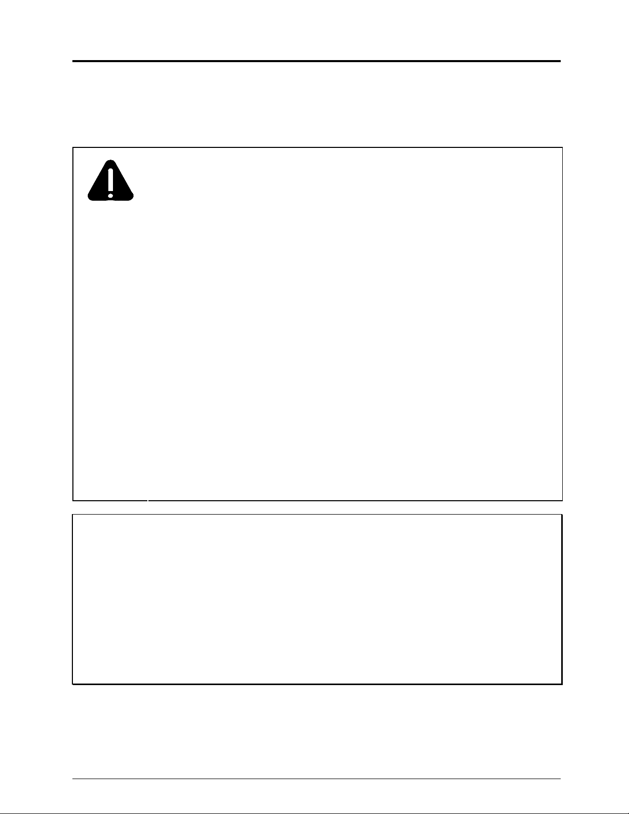
CAUTION
• This RFID device complies with FCC Radio Frequency exposure limits for an
uncontrolled environment. This equipment should be inst alled and operated
with a minimum distance of 20cm between the radiator and your body. If
20cm distance cannot be maintained, end users are to be 20cm from
printer extremity.
• Any changes or modifications to this RFID module not expressly approved
by Datamax-O’Neil Corporation will void the us er’s authority to operate the
equipment.
• RFID operation is subject to the following two conditions : (A) this device
may not cause interference, and (B) this device must accept any
interference, including interference that may cause undesired operation of
this device.
• For your safety and to avoid equipment damage, always turn OFF power
and unplug the printer’s power cord before beginning this installation and
when performing service.
•
To avoid equipment damage, never apply power to the printer with the
Antenna Cable disconnected.
Note: This equipment has been tested and found to comply with the limits for a
Class A digital device, pursuant to part 15 of the FCC Rules. These limits are
designed to provide reasonable protection against harmful interference when
the equipment is operated in a commercial environment. This equipment
generates, uses, and can radiate radio frequency energy and, if not installed
and used in accordance with the instruction manual, may cause harmful
interference to radio communications. Operation of this equipment in a
residential area is likely to cause harmful interference in which case the user
will be required to correct the interference at their own expense.
1
Page 4
Contents
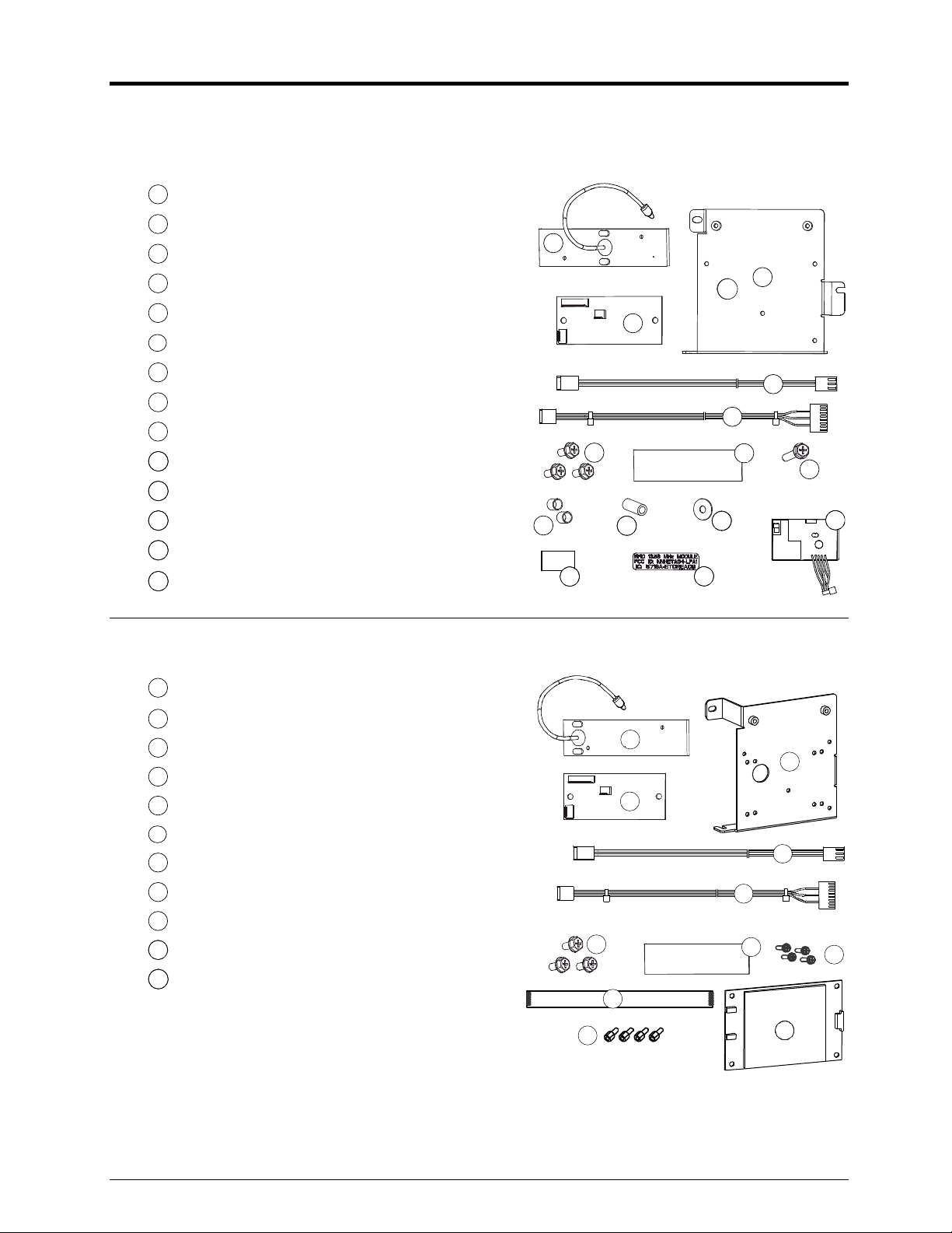
The contents of the kit differ according to the type of RFID option:
HF Option*:
1
Antenna
2
Regulator CCA
3
Mounting Plate
4
Power Cable
5
Comm Cable
6
Screw (3), M4 HD 8
7
Double-Sided Tape
8
Screw, M4 HD 25
9
Short Spacer (2), .34 X .31
10
Long Spacer, .25 X .62
11
Washer
12
RF Shield
13
FCC Label
14
HF Module
UHF Option*:
1
Antenna
2
Regulator CCA
3
Mounting Plate
4
Power Cable
5
Communications Cable
6
Screw (3), M4 x 8
7
Double-Sided Tape
8
Screw (4), M3 x 6
9
I/O Cable
10
UHF Module
11
Standoff (4) M3x13
1
6
9
10
12
1
2
6
9
3
2
4
5
7
8
11
14
13
3
4
5
7
8
11
*Also included, but not shown, is the RFID Quick Start Guide (P/N 92-2450-01).
2
10
Page 5

Tools Required
A Phillips screwdriver is needed, and a PC with an Internet conn ect ion may also be required.
Step 1: Checking Firmware
A) Verify the firmware version in the print er:
Press the TEST Button on the Control Panel.
Using the DOWN Button, scroll to PRINT
CONFIGURATION and press TEST.
READY
WED 09:32A 23APR2008
READY
PAUSE
STOP
FEED
ERROR
CANCEL
Control Panel
B) Examine the Application Version printed on
the Configuration Label and proceed
accordingly:
• If 14.09 (or greater), go to Step 2; or,
• If 14.08 (or less), go to ftp.datamax-
oneil.com and download a new version.
Follow the “Updating Firmware”
instructions in the Operator’s Manual and
install the update.
Step 2: Preparing the Printer
CAUTION
Always wear a wrist strap and follow ESD prevention measures when
handling circuit card assemblies.
MENU
CONFIGURATION
THU 09:09 AM 24APR2008
PRINTER KEY:
4210-MG10-071010-027
APPLICATION VERSION:
83-2625-10H 10.07 07/24/2007
BOOT LOADER:
83-2627-10G 10.05 06/15/2007
UNLOCKED:
CG TIMES
FPGA:
MA05
iPH:
32-56777
Configuration Label
TEST
Application Version
FORMAT ATTRIBUTES:l
XOR
LABEL ROTATION:
DISABLED
IMAGING MODE:
MULTIPLE LABEL
PAUSE MODE:
DISABLED
PEEL MODE:
DISABLED
SECURITY:
DISABLED
UNITS OF MEASURE:
IMPERIAL
INPUT MODE:
DPL
A) Turn OFF the Power Switch and unplug the
Power Switch
power cord from the AC Receptacle.
AC Receptacle
3
Page 6

B) Remove the Cover Screws on the
outside of the printer.
C) Raise the Cover. Loosen the
Cover Screws
Cover
Cover Screws
Cover Screws on the
Centerplate then remove the
Cover.
D) Remove the Fascia,
Thumbscrew and
Tearbar (or other
output attachment).
Press the Printhead
Centerplate
Printhead Latch
Printhead Assembly
Thumbscrew
Latch, and then raise
the Printhead
Assembly. Remove
media from the printer.
Fascia
Tearbar
4
Page 7

Step 3: Installing the Option
A) Peel the backing from the
Double-Sided Tape (Item 7).
Affix the Double-Sided Tape
to the recessed area of the
Antenna Mount.
If installing the HF Option,
proceed to B; otherwise, go to
C.
Double-Sided Tape
Antenna Mount
B) HF Option, only –
Peel the backing from the RF Shield (Item 12).
Affix the RF Shield to the Antenna (Item 1) in
the area as shown, right.
C) According to the option type,
cut the tape over the HF
Opening or UHF Opening in
the Antenna Mount. Route
RF Sheild
(HF Option, only)
Antenna
Antenna
Antenna Cable
the Antenna Cable through
the opening. If installing the
Antenna Mount
HF Option, orient the RF
Shield over the UHF
Opening. Affix the Antenna
HF Opening
(Item 1) in the Antenna
Mount.
UHF Opening
5
Page 8

Antenna Cable
D) Route the Antenna Cable
through the Cableway in the
Centerplate.
E) Loosen the Guide Screw
and the Heat Sink Screw
then slide the Notched
Tabs of the Mounting
Plate (Item 3)
underneath. Secure the
Mounting Plate to the
Cableway
Guide Screw
Centerplate
Centerplate
Screw
Notched
Tab
Centerplate using the
Screw (Item 6) and then
tighten the Guide Screw
and the Heat Sink Screw.
F) Secure the Regulator CCA
(Item 2) to the Mounting
Plate using the Screws
(Item 6) then proceed
according to the option
type:
Heat Sink
Screw
Mounting
Plate
Notched
Tab
Mounting
Plate
Regulator
CCA
Screws
6
Page 9

HF Option:
G) Place the Washer (Item
11) and then the Long
Spacer (Item 10) onto the
Screw (Item 8). Place a
Short Spacer (Item 9)
over the Long Spacer and
Screw. Insert the Long
Spacer and Screw
through the HF Module
(Item 14). Place a Short
Spacer (Item 9) over the
Long Spacer and Screw
then secure the assembled
parts to the Mounting
Plate, as shown.
H) Affix the FCC Label (Item
Mounting
Plate
Main Logic
CCA
Short
Spacer
HF
Module
Short
Spacer
Screw
Long
Spacer
Washer
Regulator
CCA
13) to the Mounting
Plate. Route the Antenna
Cable behind the
J12
J7
J1
J2
J3
Mounting Plate and then
connect the cables
according to the table
below:
Cable From To
Power
Supply CCA
Antenna
Cable
Antenna
Port
Mounting
Plate
I/O
Antenna Cable Antenna Antenna Port – HF Module
Power Cable (Item 4) J7 – Power Supply CCA J1 - Regulator CCA
Comm Cable (Item 5) J12 – Main Logic CCA J2 – Regulator CCA
I/O HF Module J3 – Regulator CCA
FCC Label
HF
Module
7
Page 10

UHF Option:
G) Secure the UHF Module (Item 10) to the Mounting Plate using the four Standoffs
(Item 11) and four Screws (Item 8).
Screws
Mounting
Plate
UHF
Module
Standoffs
H) Route the Antenna
Main Logic
CCA
Regulator
CCA
Cable behind the
J12
Mounting Plate and
J2
then connect the cables
according to the table
below:
Power
Supply CCA
Antenna
Cable From To
Antenna Cable Antenna
Power Cable (Item 4) J7 – Power Supply CCA
J7
Cable
J1
J1
J3
J2
Mounting
Plate
Antenna
Port
Antenna Port J1 – UHF
Module
J1 - Regulator CCA
Comm Cable (Item 5) J12 – Main Logic CCA J2 – Regulator CCA
UHF
Module
I/O Cable (Item 9) J2 – UHF Module J3 – Regulator CCA
8
Page 11

Step 3: Returning Operation
A) Dress the installed cables into the
existing cable bundle. RECHECK ALL
CONNECTIONS. Lower and latch the
Printhead Assembly. Replace the
Cover. Reinstall and tighten the three
Cover Screws.
B) Replace the Tearbar and
Thumbscrew (or other output
attachment). Replace the
Fascia. Tighten the Cover
Screws on the Centerplate.
Cover Screws
Cover Screws
Centerplate
C) Plug the power cord into the AC Receptacle
and turn ON the Power Switch.
Power Switch
AC Receptacle
9
Page 12

D) Enable the option by following the instructions
below:
READY
STOP
USER MENU
MEDIA SETTINGS
PRINT CONTROL
PRINTER OPTIONS
SYSTEM SETTINGS
EXIT
SYSTEM
ERROR
ENTER
Control Panel
MENU
TEST
Step Instruction Displayed Message
a Press the MENU Button on the Control Panel.
Using the DOWN Button, scroll to PRINTER
b
OPTIONS and press the ENTER Key.
c Scroll to RFID and press ENTER.
d Press ENTER.
USER MENU
MEDIA SETTINGS
PRINTER OPTIONS
MODULES
RFID
RFID MODULE
RFID MODULE
DISABLED
e Scroll to the installed modu le type and press ENTER.
Press the EXIT Key, and then the YES Key.
f
(A reset will occur then, following init ialization, the
RFID
RFID MODULE
READY
RFID
RFID Indicator will appear.)
Note: If an RFID FAULT occurs, ensure that the
correct module has been selected. If the
fault continues, recheck the installation.
This completes installation. Refer to the RFID Quick Start Guide to begin using the option.
10
 Loading...