

Page 1
92-2479-01 Rev.E
Peel & Present Option
Page 2

Page 3
Contents of the Peel & Present Kit
This kit contains the following items:
Peel and Present Mechanism
Assist Roller and Bushing
NOTE: If this option was ordered with the printer the Assist
Roller and Bushing will already be installed in the printer.
Proceed to Step 3: Installing the Peel & Present Mechanism.
Otherwise follow the steps below to install these items into
the printer.
Other Requirements
This option requires the Internal Rewinder option. Contact your sales representative for more information.
Tools Required
To install this option you will need a #2 Flathead and a #2 Phillips head screwdriver.
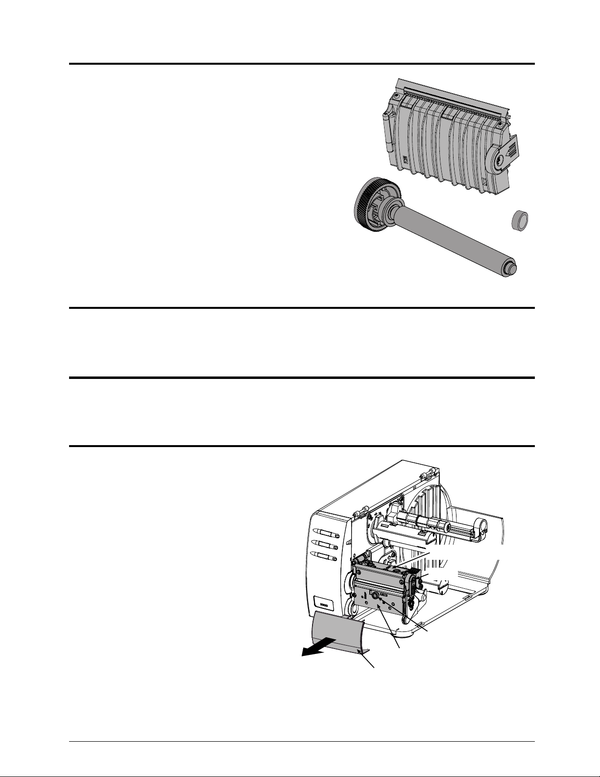
Step 1: Preparing the Printer
Turn ‘Off’ the power switch and unplug the
printer.
Open the cover. Press in Latch and raise the
Printhead Mechanism.
Remove any media from the printer.
Remove the Fascia by gently pulling it
forward.
Loosen and remove the Thumbscrew, then
remove the Tear Plate.
Tear Plate
Fascia
Printhead Mechanism
Latch
Thumbscrew
1
Page 4

Using a #2 Philips head screwdriver, remove
the Screw that secures the Side Plate to the
printer.
Remove the Side Plate.
Side Plate
Screw
Using a #2 Philips head screwdriver, remove
the Screw that secures the Bearing Cap to the
printer.
Remove the Bearing Cap and the Hole Plug.
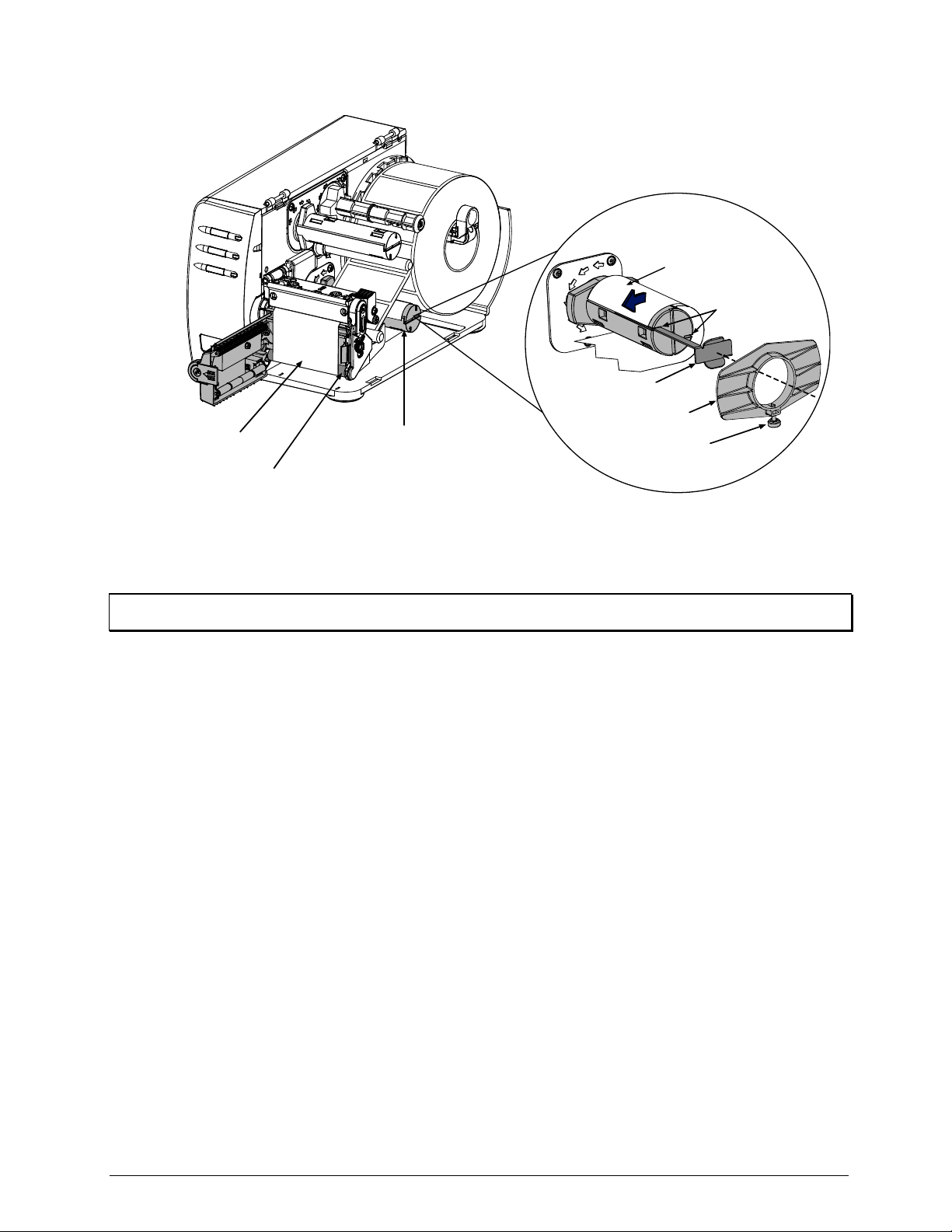
Step 2: Installing the Assist Roller
Insert the Assist Roller, as shown, gears first
into the printer.
Pivot the other end of the roller into the
Bearing Block.
Screw
Hole Plug
Bearing Cap
Assist Roller
2
Bearing Block
Page 5

Insert the Bushing completely into
the Bearing Block.
While holding the Assist Roller
Bearing against the Centerplate,
replace the Bearing Cap.
Hold the Bearing Cap in place and
secure it with the Screw.
Replace the Side Plate and start, but
tighten the Screw.
do not
Assist Roller
Bearing Cap
Screw
Centerplate
Assist Roller Bearing
Bushing
Bearing Block
Side Plate
Screw
3
Page 6

Ensure that the Leveling Cam is
loose, and then close and latch the
Printhead Assembly.
Printhead Assembly
While pushing down on the
Printhead Assembly, as shown, pull
Leveling Cam
down on the Side Plate and tighten
the Screw.
Screw
Side Plate
Verify Latch Operation:
- Open and close the printhead assembly, verify that the latch is fully engaged. If you are unable to get
the printhead to latch, the side plate is too low.
- Pressing down on the printhead assembly should not cause the latch to loosen or reveal any gap at the
latch point. If there is a gap or movement in the latch then the side plate is too high.
- Print some sample labels. If degraded print quality or ribbon tracking problems are observed then the
side plate is not positioned correctly.
Step 3: Installing the Peel & Present Mechanism
Position the Peel and Present Mechanism
for mounting on the front of the printer.
Tighten the Mounting Screw to secure
the mechanism to the printer.
This completes the installation process.
Proceed to Loading Media to begin use.
Mounting Screw
Peel and Present Mechanism
4
Page 7

Loading Media
With the Peel and Present option, labels printed in a batch will be automatically be separated from the
backing material and dispensed “on-demand”– that is, printing will occur only after a previously printed
label has been removed from the printer.
Press in the Latch to open the mechanism.
Swing the mechanism open.
Load the printer with media (see the
Operator’s Manual for detailed instructions).
Load media into the printer as you normally
would for tear-off operation (see the
Operator’s Manual for details), however,
extend an additional 12 inches (30 cm) of
media out the front of the printer.
From this 12 inches (30 cm) of media, remove
all of the labels, so that only the Backing
Material remains.
Latch
Backing Material only
5
Page 8
Route the Backing Material under the Assist Roller and around the Internal Rewinder, as shown
below.
Backing Material
Slots
Media Clip
Retainer
Backing Material
Assist Roller
Internal Rewinder
Thumbscrew
Note: The Media Retainer can be used in place of the Media Clip for a more consistent rewound roll. The Media
Clip and Media Retainer cannot be used together.
Put the leading edge of the Media into a Slot on the Internal Rewinder and insert the Media Clip. Be
sure the leading edge of the Media is cut square and that is inserted evenly into the slot.
Manually rotate the Internal Rewinder to remove slack from the Media.
Plug in and turn ‘On” the printer. After initialization, press the FEED Button to align the next label to
the top of form position. (If a peeled label is presented, remove it to proceed.) The printer is now ready
for on-demand use.
6
Page 9
Setup, Configuration, and Operation
The Peel and Present option is plug and play; no setup or configuration is required. As soon as power is
applied, the printer senses and enables the Present Sensor for operation.
During operation, when a label is present (blocking the sensor), the yellow Stop Light on the front panel of
the printer will flash to prompt you that a label awaits removal.
With printers equipped with an LCD display, the display will read “REMOVE LABEL”
Notes: (1) The operation of the Present Sensor can also be controlled via software commands from the host. Be
sure that your software program is properly configured for use with this option. (2) If the Present Sensor is
disconnected without first powering off the printer, the printer will behave as if there is a label blocking the
sensor. Turn the printer off and then back on. The printer will reconfigure itself to operate without the
Present Option
Unloading the Internal Rewinder
When the Internal Rewinder becomes full remove the Media Clip. Grasp the used backing material and
pull it from the Internal Rewinder.
Note: Never allow the outer diameter of backing material to exceed 4 inches (102 mm) on the Internal Rewinder.
Periodic Maintenance
The Peel Mechanism Rollers will need to be disassembled and cleaned approximately every 100,000
inches to ensure trouble free operation. This cleaning interval may be more or less depending on the type
of adhesive on the back of your media. Heavy or “gummy” adhesive will require more frequent cleaning.
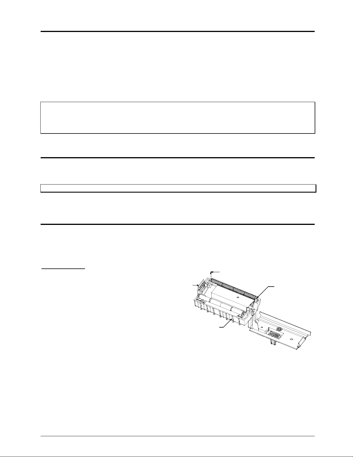
Upper Rollers:
Remove the Peel Mechanism from the printer.
Press in on the Latch and allow the Front Cover
to swing open.
Remove the small C-Clip from the Upper
Roller Shaft.
C-Clip
Latch
Front Cover
Upper Roller
Shaft
7
Page 10
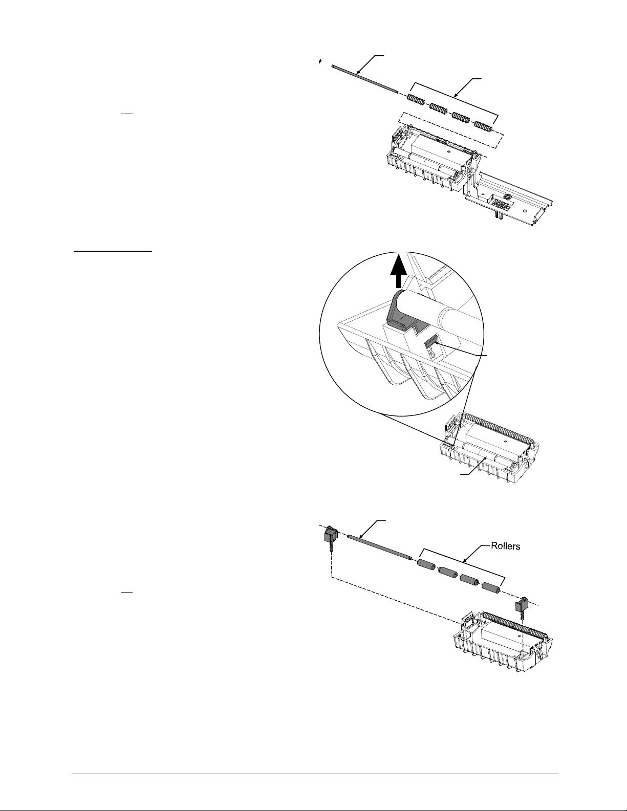
Remove Upper Roller Shaft and associated
Rollers.
Clean all
surfaces of the Rollers and the Upper
Roller Shaft. Isopropyl Alcohol can be used,
for heavy or stubborn deposits WD-40
or an
adhesive remover can be used. Be sure all the
ridges on the rollers are free of debris.
Re-assemble the Upper Roller Shaft, Rollers,
and C-Clip into the Peel Mechanism Assembly.
Lower Rollers:
Remove the Peel Mechanism from the printer.
Press in on the Latch and allow the Front Cover
to swing open.
Push in on the Tab as shown, repeat for the
other side and then remove the entire Lower
Roller Assembly.
Upper Roller
Shaft
Rollers
Push in on Tab
Remove Lower Roller Shaft and associated
Rollers. Note the order of the Rollers as they
are removed, they must be re-installed in the
same order.
Clean all
surfaces of the Rollers and the Lower
Roller Shaft. Isopropyl Alcohol can be used,
for heavy or stubborn deposits WD-40
or an
adhesive remover can be used. Be sure all the
ridges on the rollers are free of debris.
Re-assemble the Lower Roller Shaft and
Rollers. Reinstall the assembly into the Peel
Mechanism Assembly
Lower Roller
Assembly
Lower Roller
Shaft
8
 Loading...