

Page 1
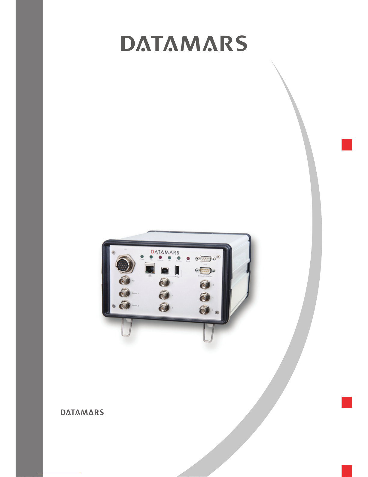
R-IN1300 MC
HF – multi read
TEXTILE ID
USER MANUAL
Version 6.0
Corporate Headquarters - Textile ID business division:
Via Industria 16
6814 Lamone
Switzerland
Phone: +41 91 935 73 80
Fax: +41 91 945 03 30
[email protected]
www.textile.datamars.com
Page 2

DATAMARS
R-IN 1300 MC User Manual – Rev 6.0
1 (50)
TABLE OF CONTENTS
1 Introduction................................................................................................................................2
2 Hardware connections ..............................................................................................................4
2.1 Mounting ............................................................................................................................5
3 ‘Single Channel Mode’ Version.................................................................................................6
4 Operation with terminal .............................................................................................................7
4.1 List of the commands of the reader...................................................................................7
4.2 Generic Settings ................................................................................................................7
4.3 ISO 15693 settings ..........................................................................................................12
4.4 I-Code I settings...............................................................................................................13
4.5 Expert Antenna Setup......................................................................................................13
4.6 USB settings ....................................................................................................................15
4.7 Memory Pen Settings ......................................................................................................15
5 Operation with Graphical User Interface (GUI).......................................................................17
5.1 Connecting with the COM (RS-232) ................................................................................17
5.2 Connecting with Ethernet (Recommended) ....................................................................17
5.3 General Considerations...................................................................................................17
5.3.1 Third Party Interface..............................................................................................18
5.3.2 Human Interface....................................................................................................18
5.3.3 Login ......................................................................................................................19
5.4 Logout ..............................................................................................................................20
5.5 Network Setup .................................................................................................................21
5.6 RS 232 Setup...................................................................................................................21
5.7 Reader Setup...................................................................................................................22
5.8 Advanced Reader Setup..................................................................................................24
5.9 Antenna Selection............................................................................................................25
5.10 Combo Reader Setup – Advanced Combo Setup.......................................................27
5.11 Monitor..........................................................................................................................28
5.12 Configurations ..............................................................................................................29
5.13 Firmware Update..........................................................................................................30
5.14 License .........................................................................................................................31
5.15 USB Setup....................................................................................................................32
5.16 Tuning...........................................................................................................................32
5.17 System Requirements.................................................................................................33
6 USB-Device.............................................................................................................................34
6.1 USB Serial Emulation ......................................................................................................34
6.1.1 First usage.............................................................................................................34
6.1.2 Further usage ........................................................................................................36
6.1.3 How to discover which COM-Port corresponds to the USB-Serial-Emulation......36
6.2 USB Mass Storage Emulation .........................................................................................38
7 Memory Pen............................................................................................................................39
8 Tuning .....................................................................................................................................41
9 Technical specifications for R-IN1300 MC..............................................................................43
9.1 Operational characteristics ..............................................................................................43
9.2 Electrical characteristics ..................................................................................................43
9.3 Regulations ......................................................................................................................44
9.3.1 Equipment Modification.........................................................................................44
9.3.2 EN 300330-1/-2 (Europe)......................................................................................44
9.3.3 FCC (USA).............................................................................................................44
9.3.4 IC (Canada) ...........................................................................................................44
9.3.5 CE certification ......................................................................................................45
9.3.6 Warranty ................................................................................................................45
Appendix A - Connecting the R-IN1300 MC to a PC with a cross cable .....................................46
Appendix B - Code length.............................................................................................................48
Appendix C - I/O Pin Configuration..............................................................................................49
Appendix D - Troubleshooting ......................................................................................................50
Page 3
DATAMARS
R-IN 1300 MC User Manual – Rev 6.0
2 (50)
1 INTRODUCTION
The Datamars “R-IN1300 MC” High Frequency (HF) RFID-reader, designed to work in industrial
environments, is resistant to vibrations, electromagnetic interference and able to detect the following
transponder technologies:
T-BT 1320, T-BT1315, T-BT1311 (ISO 15693), HF
T-BT 7xxx series, LF (only with Datamars R-IN7500 reader connected externally)
I-Code-1
Other types of transponders could be read in “Combo” mode.
The reader is able to find simultaneously more than one High Frequency (HF - multi read)
transponder1 and one Low Frequency (LF – single read) chip at the same time if you have a
R
-IN7500 Low Frequency reader connected on the Secondary Interface.
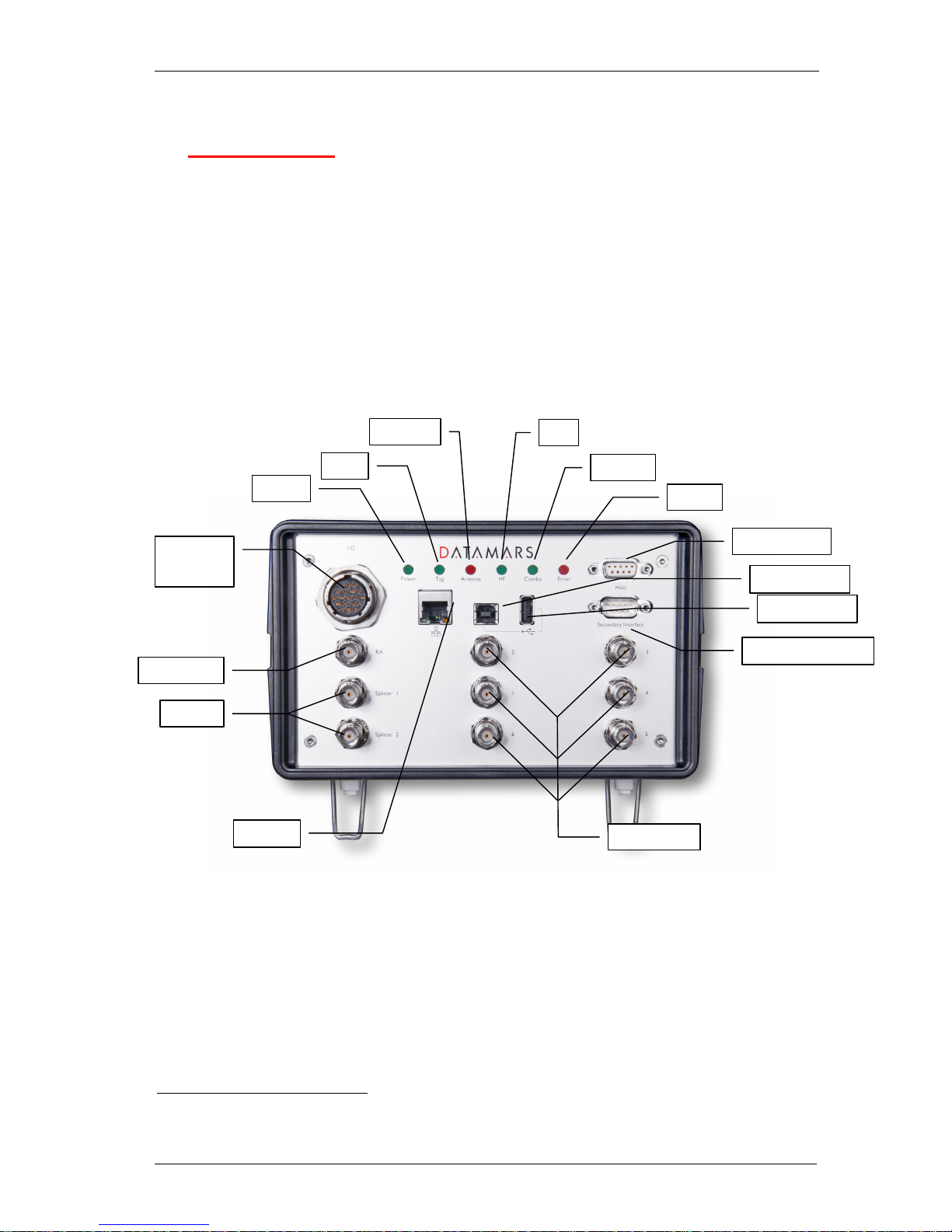
LEDs
Power Light on when the reader is switched on
Tag Light on when one or more transponder are detected
Antenna Light on when the antenna is not tuned or is near metallic objects or
not connected
HF High Frequency reading is ON
Combo The system is working in Combo mode (see chapter 2)
Error General Error
Antennas
HF Antennas TX/RX antenna channels from 1 to 6
1
the quantity of transponders detected and the accuracy can change depending on the used transponder, the environment, the
size of the antenna, etc.
Secondary Interface
Host Interface
Digital I/O
and
buzzer
HF Antennas
Power
Tag
Antenna
RX
Splitter
HF
Combo
Error
USB device
Ethernet
USB host
Page 4
DATAMARS
R-IN 1300 MC User Manual – Rev 6.0
3 (50)
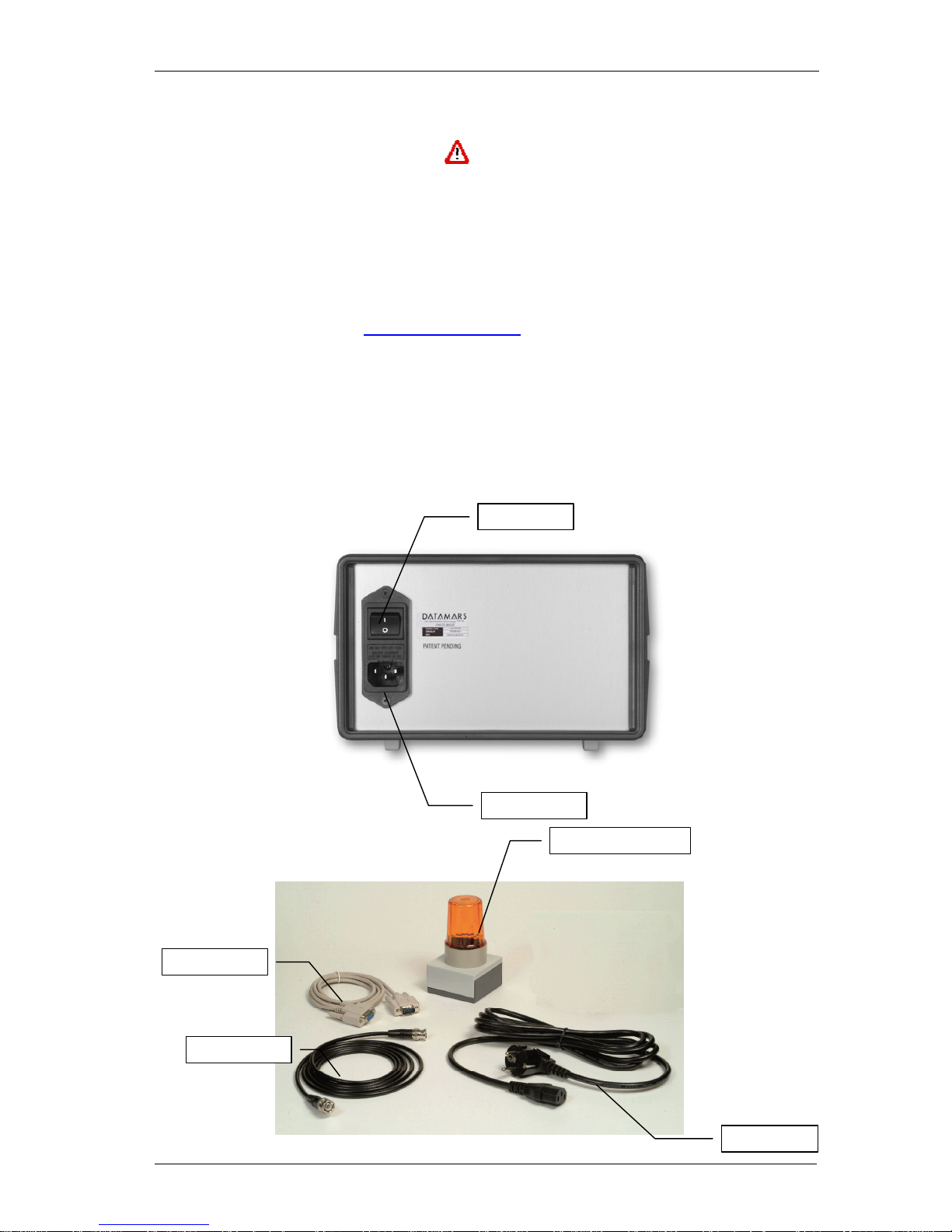
Splitter 2 splitted channels (0° phase shift).
Use 2.5m cable supplied by Datamars upon request.
RX Antenna RX channel very sensitive!
Interfaces
Digital I/O Digital Inputs and Outputs (see appendix C).
Host Connect to any serial port (COM) on your PC with RS-232 cable or to
any other RS232 Terminal.
Secondary Interface Used in Combo mode (see chapter 2).
USB Connect external USB-devices
Ethernet (Web Server) Connect to LAN with a standard Ethernet cable.
For more info in Ethernet communication please request the “R-
IN1300 TCP/IP Dedicated Protocol” manual to
Buzzer Plug the buzzer into the Digital I/O connector
Power Switch Turn ON and OFF the reader.
Power Supply Connect the power supply cable (100-240VAC, 50-60 Hz).
Internal Battery 3V lithium battery CR1225FH
Caution: Risk of explosion if battery is replaced by an incorrect type. Dispose of used batteries
according to instructions.
Power Supply
Power Switch
Coaxial Cable
RS-232 Cable
Power Cable
Optional: Buzzer Box
Page 5
DATAMARS
R-IN 1300 MC User Manual – Rev 6.0
4 (50)
2 HARDWARE CONNECTIONS
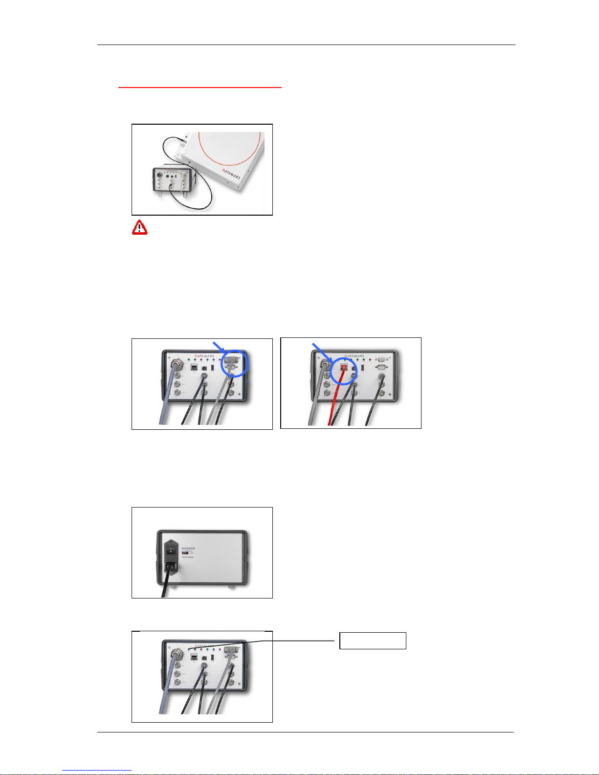
1. Antenna:
Connect the black coaxial cable from the antenna to the connector marked as “1”.
You can not use cable other than the 3.5m coaxial 50Ω cable supplied by Datamars
SA. Additional extension cables at disposal.
2. PC/Terminal or Ethernet
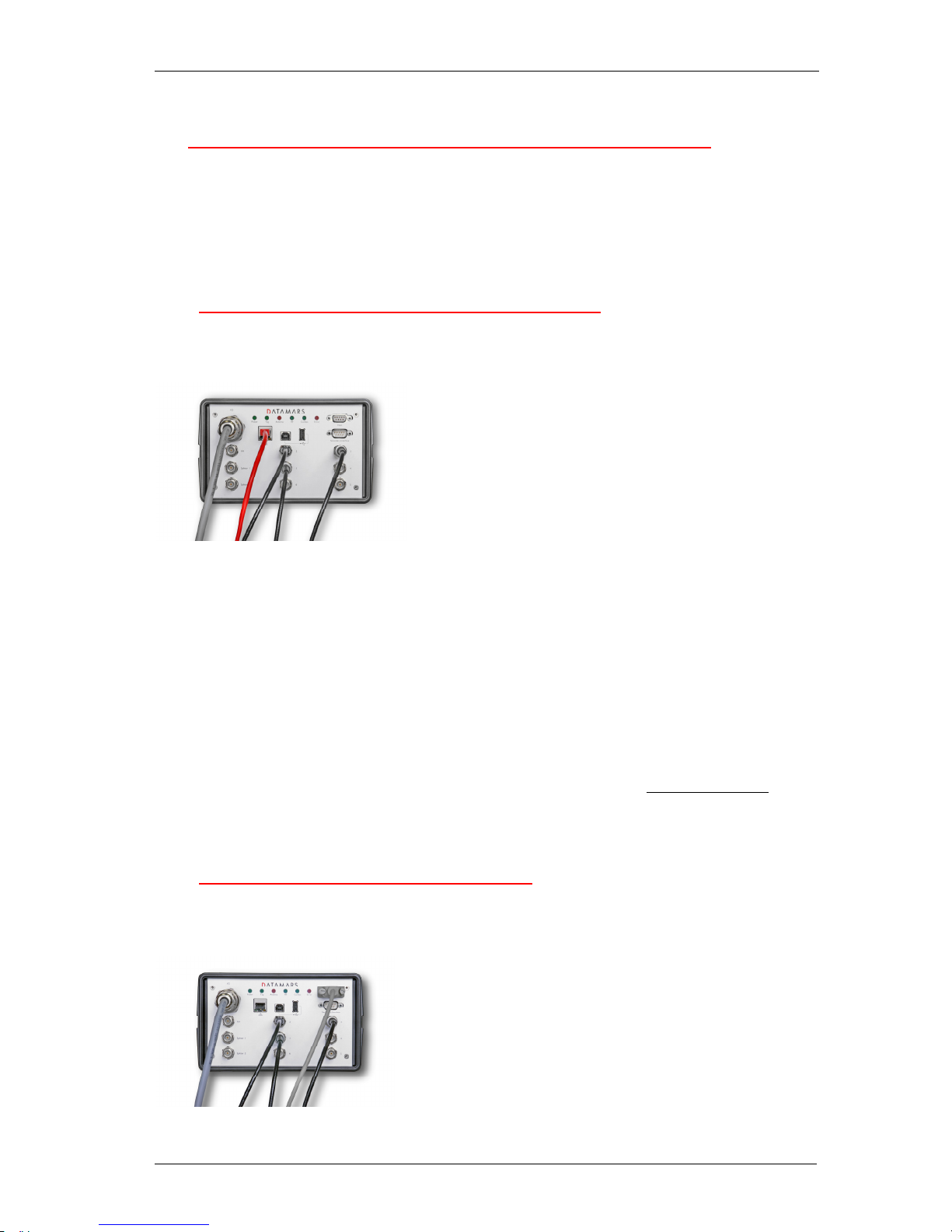
It’s possible to connect the reader in three possible ways:
(1) Use the white serial white cable from the connector marked “Host” to any serial port
(COM) on your PC.
(2) Use the USB cable from the connector USB Device to any USB port on your PC(serial
emulation).
(3) Connect the reader to a LAN just like a PC (Ethernet cable & RJ-45 connectors)
A
direct Ethernet connection between a PC and “R-IN1300 MC” reader is also possible, with
an Ethernet Cross Cable (supplied together with the reader). Refer to Appendix A for more
details on how to do this.
3. Power
Connect the power cable 100 – 240 V AC and be sure that it is well fixed.
4. Set the Power Switch to ON and check if the green LED (Power) is on.
5. Wait until lights “Tag” and “Antenna” stop flashing (~10 seconds).
Green light on
Page 6

DATAMARS
R-IN 1300 MC User Manual – Rev 6.0
5 (50)
IMPORTANT:
Please place the antenna as far as possible from metal surfaces to avoid possible
reading interferences and avoid mounting it in places where regular ventilation is not
granted.
If the light “Antenna” turns on, the antenna might be too close to metal surfaces, not
tuned or the coax cable may be damaged.
After the reader is turned on for some time the temperature might increase.
If you install more than one “R-IN1300 MC” with antenna, be sure to set *mi1
(modulation index 30%).
Do not plug/unplug any connectors while the reader is turned ON.
If you have a new R-IN7500 NMS:
1. Connect the Low Frequency (LF) Antenna to the connector marked “Ant.1” on the reader.
2. Connect a serial cable “RS-232” mentioned on the R-IN7500 to the connector “Secondary
Interface” mentioned on the “R-IN1300 MC” reader.
3. Connect the power cable.
4. Turn the reader on.
Keep a distance between the LF and the HF antenna (min. 1m) in order not to influence the
reading distance or use a combo antenna (A-ST1330 CBO) to read LF and HF transponders at
the same time with the same antenna.
Although R-IN1300 MC is protected against ESD, to avoid reader malfunction make sure
that no direct electrostatic discharge will happen into the reader case, antennas or even on
metallic parts directly in contact with the reader enclosure or antennas structure. Typical case
is ESD from metallic cart coming in contact with tunnel antenna metallic structure and
shielding.
2.1 MOUNTING
The reader can be simply laid down on the table or be mounted on the wall or under a table using its
appropriate wall mounting system.
Page 7
DATAMARS
R-IN 1300 MC User Manual – Rev 6.0
6 (50)
3 ‘SINGLE CHANNEL MODE’ VERSION
The functions of the reader are grouped into categories. Each category is dedicated to a specific task
i.e. reading UIDs in different industrial environments, exchanging data with the reader via serial and
Ethernet connections, monitoring the reader’s activities and so on.
The most important categories of commands are made available per default by the reader which is
thus able to perform tasks normally required in standard industrial environments. A special category of
commands is used to enhance the capabilities of the reader for special purposes. This special
category is not active per default: it must be activated typing the reader specific license-code.
The license-code can be requested by contacting Datamars and it is activated via terminal with
command *li immediately followed by the code itself or via browser typing the license-code in the
License-Tab.
The basic version of the reader, the so-called R-IN1300 MC SCM, can thus be upgraded to the more
powerful version, the so called R-IN1300 MC.
R-IN1300 MC SCM readers only use Antenna 1, Splitter and Rx and thus they can only be used in
Single Channel Mode.
R-IN1300 MC readers can use Antenna 1, 2, 3, 4, 5, 6, Splitter and Rx.
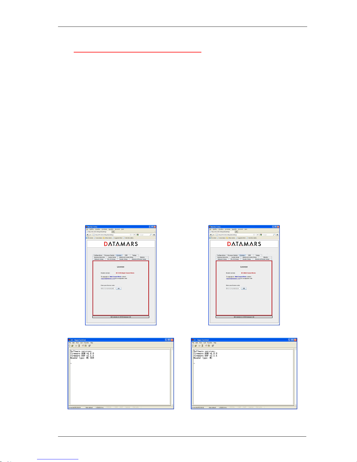
Given a reader, it is possible to know whether it is a MC SCM or MC using the version-command (*v)
given by terminal or opening a browser-connection to the reader (see next chapters)
Browser
Terminal
ARM: 4.0.0 / DSP 2.1.4
Type: MC SCM ARM: 4.0.0 / DSP 2.1.4
Type: MC
Page 8
DATAMARS
R-IN 1300 MC User Manual – Rev 6.0
7 (50)
4 OPERATION WITH TERMINAL
For operation with terminal use any kind of terminal, e.g. Windows HyperTerminal with the following
settings:
• Bits per second 115200
• Data bits 8
• Parity None
• Stop bits 1
• Flow control None
4.1 LIST OF THE COMMANDS OF THE READER
All commands must be followed by a carriage return (ENTER).
General Commands Explanation
*d Detect:
returns the UID-list of all the HF transponders in the field
*i Interrupts any continuous mode operation (does not disable the
continuous mode)
*x List of the commands and settings
*v Version (ARM + DSP)
*se Settings:
Displays the current settings (Notice that the settings are maintained
after power off)
*st Store UIDs
Usage: with the command “*st” switch from the state “Store UIDs off”
to the state “Store UIDs on”. Then start reading with the command
“*d”. The detected tags are not sent to the output devices but are
cumulated internally. Using now the command “*dw” the reading
process is stopped and the cumulated detected UIDs are sent to the
output devices all at once.
*dw Download UIDs (this command is coupled with *st – see above)
*li[_] Enter the reader-specific license code (upgrade). The license code is
a 16-char long sequence (allowed chars 0,1,2…9, A,B,C…F (case
insensitive))
Example: *liA03E45BC08C532BC
4.2 GENERIC SETTINGS
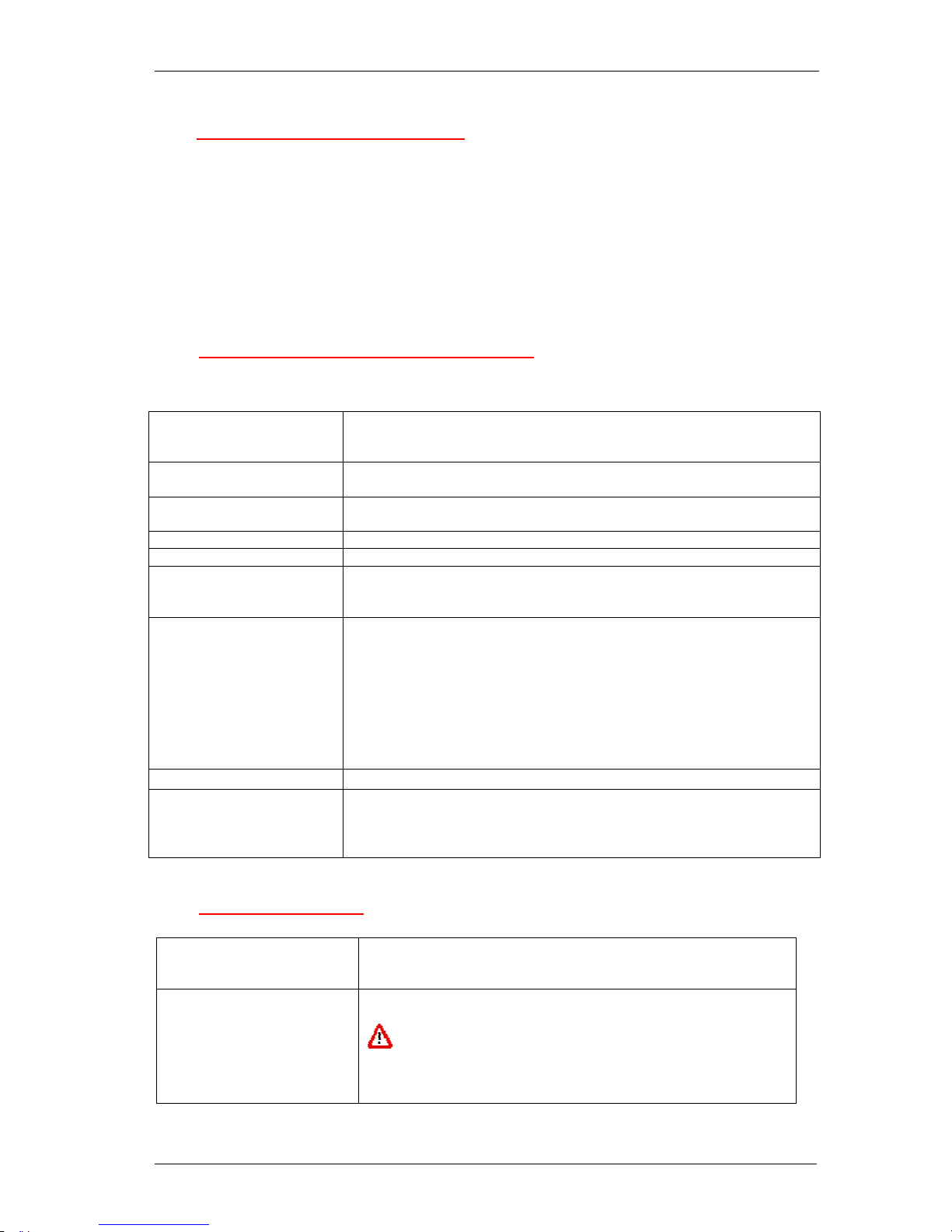
General settings Explanation
*rd Restore default settings
Any previously user defined settings will be deleted and
replaced by factory defaults.
Confirmation: “Default settings restored”
Page 9
DATAMARS
R-IN 1300 MC User Manual – Rev 6.0
8 (50)
*co[_] Continuous mode:
*co1 continuous mode on (default)
*co0 continuous mode off
*in[_] Number of inventories (for non continuous mode only)
*in[1..9] (default 1 [inventory], example *in5)
*id[_] Delay (ms) between two inventories (for non continuous mode
only)
*id[0..1000] (default 0ms, example *id530)
*rh[_] Remove headers:
*rh0 does not remove the headers
*rh1 removes the headers (default)
*ec[_] Echo:
*ec0 echo disabled (default)
*ec1 echo enabled
“echo” makes it possible to view the characters sent to the
reader.
*sa[_] Stand alone mode:
*sa0 stand alone mode disabled (default)
*sa1 stand alone mode enabled (detect)
When stand alone mode is enabled, the device will start reading
as soon as it is turned on.
*bu[_] Buzzer Box (beeper).
*bu0: buzzer disabled
*bu1: buzzer activated on tags-detection
*bu2: buzzer activated on antenna-transmission
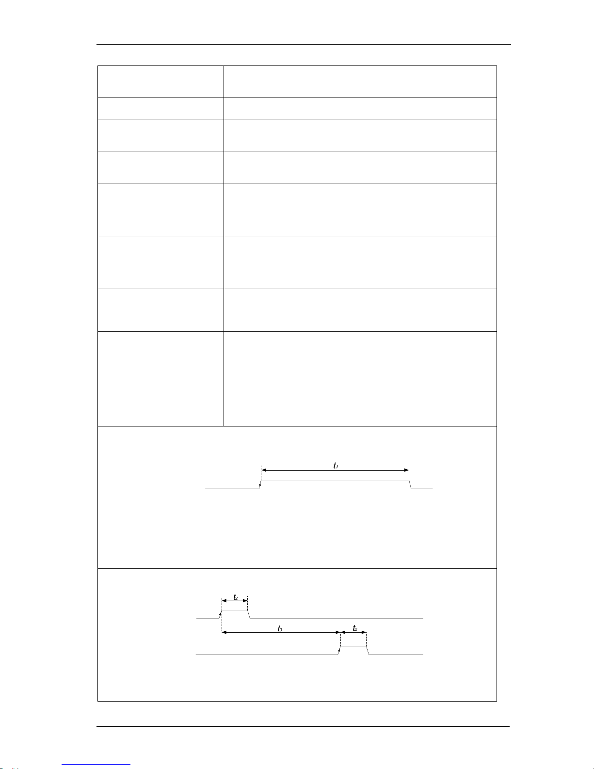
*it[_] Input trigger: The reader will start working only when the external
inputs will allow it, as shown in the following details.
Recommended for single-read operational mode.
*it0 input trigger disabled (default)
*it1 input trigger 1 enabled
*it2 input trigger 2 enabled
*it3 input trigger 1 enabled (reversed edge-logic)
*it4 input trigger 2 enabled (reversed edge-logic)
Details for *it1:
IN1
Use:
• When IN1 is high level, it’s possible to read the transponder.
• t1 min 50 ms.
• See Appendix C to know where IN±1 pins are located in the I/O connector.
• See Appendix B for electrical characteristics of the input.
Details for *it2:
IN2
Use:
• The rising edge of IN1 starts reading.
• The rising edge of IN2 stops reading.
IN1
Page 10
DATAMARS
R-IN 1300 MC User Manual – Rev 6.0
9 (50)
• t2 min 5 ms
• t3 min 100 ms
• See Appendix B to know where IN1 or IN2 pins are.
• See Appendix B for electric characteristics of the input.
*nl[_] New Line character(s) selection:
*nl0 line feed and carriage return (0x0D 0x0A) (default)
*nl1 line feed (0x0A)
*nl2 carriage return (0x0D)
*nl3 carriage return and line feed(0x0A 0x0D)
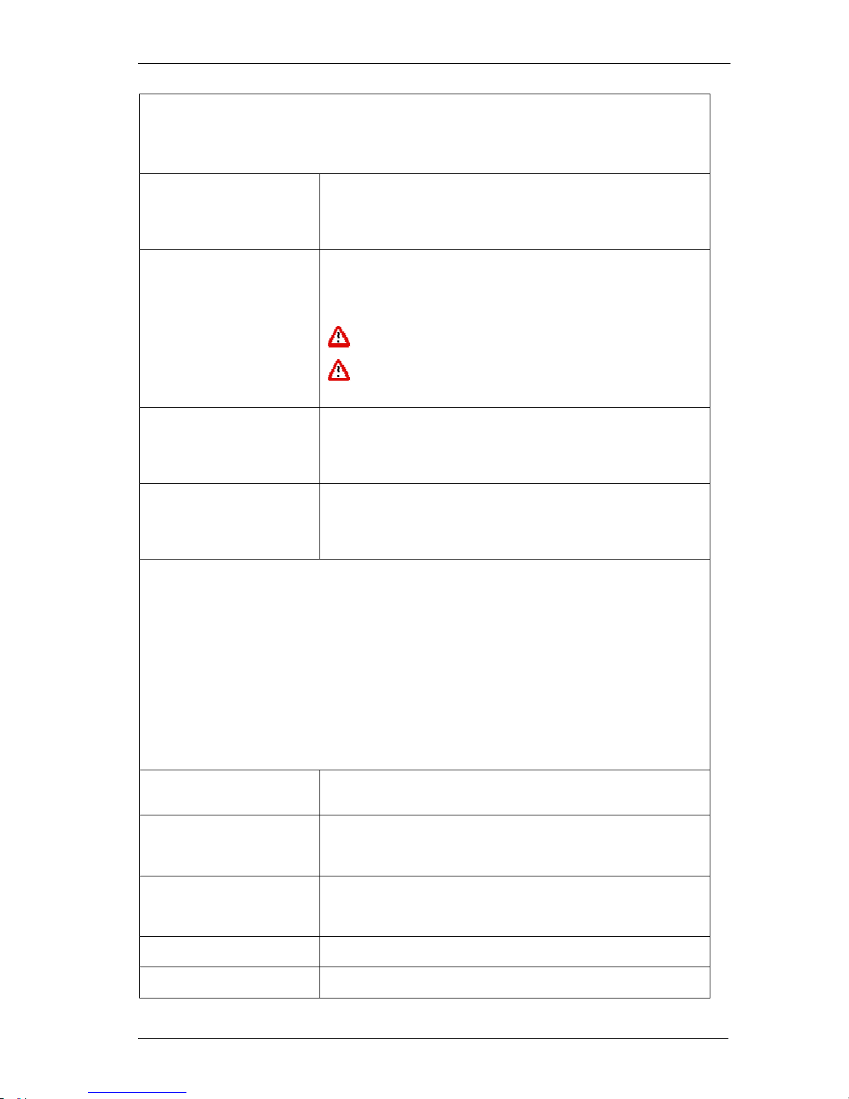
*pw[_] Output power:
*pw[0..12000] range of power from 0 to 12000 mW (default 4000
mW)
- Example *pw4000
The selected output power is an approximate value.
Check the maximum power supported by your antenna
before raising the power of the reader higher than 4000 mW.
*dt[_] Time between UIDs:
This parameter inserts a time delay between the transmissions of
codes.
*dt[0..200] range of time between UIDs from 0 to 200 units
(default 0), 1 unit = 10ms (example: *dt10 >> 100ms)
*lc[_] Lock code:
*lc0 lock code disabled (default)
*lc1 lock code 1 enabled
*lc2 lock code 2 enabled
*lc3 lock code 3 enabled
Details for *lc1:
Any transponder is read just once.
To read a transponder again, another one must be read first.
The transponder is first detected only once without regard to the time spent in the field.
Details for *lc2:
A chip can be read again only if it has been outside the reading area for more than *ti[_]
seconds.
Details for *lc3:
A transponder can be read again only if it has been outside the reading area meanwhile at least
*cn[_] different transponders have been read.
*ti[_] Time out:
*ti[0..180] time parameter for lock code 2 from 2 [s] to 180 [s]
(default 10 [s], example *ti10)
*cn[_] Number of transponders to be read before releasing a lock on
tag previously read:
*cn[1..9] counter parameter for lock code 3 from 1 to 9 [tags]
(default 2 tags, example *cn7)
*sk[_] Skip time slot on no response:
*sk0 skip on no response off
*sk1 skip on no response on (default)
*ct[_] Collision threshold parameter:
*ct[0 .. 100] parameter from 0 to 100 (default 33, example *ct33)
*cs[_] Channel Selection:
*cs0 channel I (default). Cable length must be 3,5m (ev. + 7,2m
Page 11

DATAMARS
R-IN 1300 MC User Manual – Rev 6.0
10 (50)
extensions).
*cs1 channel I and Q. There are no limitations on the cable
length.
Note: In order to safety switch channel, the reader is
automatically stopped before executing this command.
*et [_] Communication selection :
*et0 Ethernet
*et1 RS232
*et2 RS232 and Ethernet (default)
*br[_] baud rate:
*br0 baud rate 9600
*br1 baud rate 19200
*br2 baud rate 38400
*br3 baud rate 57600
*br4 baud rate 115200 (default)
*cl[_] Code length:
See Appendix A for more details.
*cl0 16 characters UIDs (standard, default)
*cl1 15 characters UIDs (Partial code)
*cl2 14 characters UIDs (Partial code)
*cl3 13 characters UIDs (Partial code)
*cl4 12 characters UIDs (Partial code)
*cl5 12 characters UIDs (First character special)
*cl6 11 characters UIDs (Partial code)
*cl7 10 characters UIDs (Partial code)
*cl8 9 characters UIDs (Partial code)
*cl9 8 characters UIDs (Partial code)
Attention: code maybe not unique with the selected code length
*tt[_] Tag technology:
*tt1 tag technology ISO 15693(T-BT1320 T-BT1315) (default)
*tt2 tag technology NXP I-Code I
Example:
*tt1: only ISO
*tt2: only I-Code I
*tt12: both ISO and I-Code I
*if Plots the current (TCP/IP) network configuration of the reader
including submask and default gateway
*ip[_-_-_-_] Configure the IP (Internet Protocol) number of the reader.
Example:
*ip192-168-0-1
Sets the IP number 192.168.0.1
The default IP number of any new reader is 192.168.0.85
*ipsb[_-_-_-_] Set the IP sub-mask associated to the local IP address:
Example:
*ipsb255-255-254-0 set the new sub mask for the eth0 IP
interface
*ipgw[_-_-_-_] Set the IP address of the local gateway:
Example
*ipgw192-168-0-201 set the gateway address to 192.168.0.201
T
o remove the default gateway: *ipgw0-0-0-0
*at[_] Selects the type of antenna connected to the reader.
*at0 Generic 3D antenna
*at1 Table-Top Antenna (default)
Page 12
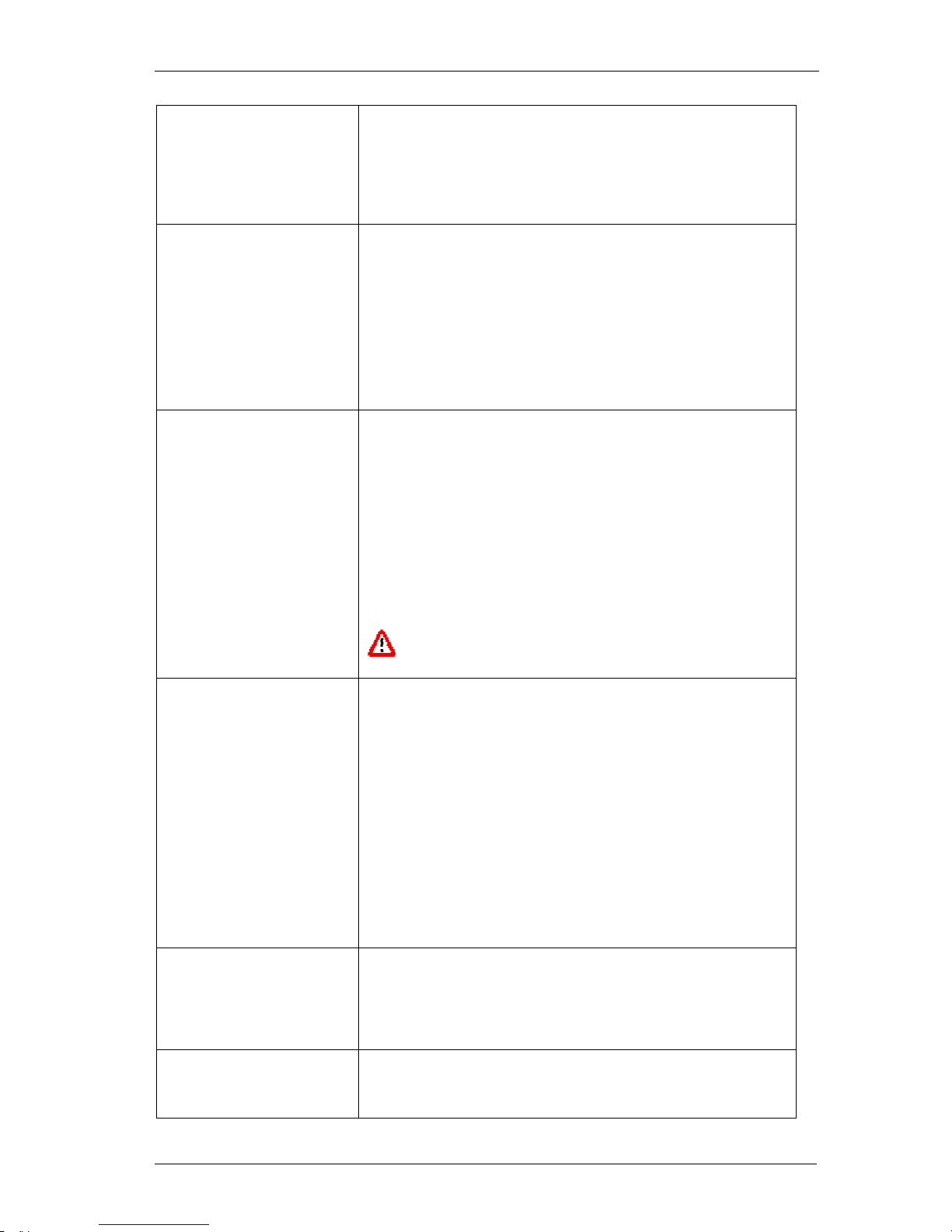
DATAMARS
R-IN 1300 MC User Manual – Rev 6.0
11 (50)
*at2 Tunnel Antenna (Cyclic switching scheme)
*at3 Tunnel Antenna (Progressive switching scheme)
*at4 Tunnel Antenna (Cyclic/Progressive switching scheme)
*at5 Bin Antenna (5W Power and quite mode set as default)
Quiet mode set as default for Tunnel Antenna
See the user manual of the specific antenna for further details.
*ha[_] Antenna Enumeration:
When enabled, each UID will include a number indicating which
channel (antenna) read it.
Example:
3 E00123456789ABCD
Antenna 3 has read the UID E00123456789ABCD
*ha0: disable antenna enumeration (default)
*ha1: enable antenna enumeration
*an[_] HF antenna select:
Selects the channel to which the antenna is connected (if the
reader is Multi-channel).
*an1: select HF antenna 1 (default)
*an2: select HF antenna 2
*an3: select HF antenna 3
*an4: select HF antenna 4
*an5: select HF antenna 5
*an6: select HF antenna 6
*an7: select Splitter antenna 7: corresponds to the splitter: the
two channels marked with “Splitter 1” an “Splitter2” (on the front-
panel of the reader) are activated at the same time each one
using the half of the power
This command is valid only with antenna types 0 and 1
(*at0 and *at1)
*cb[_] Combo Mode:
This mode allows connecting a secondary reader to the “R-
IN1300 MC”.
*cb0: Combo mode disabled (default)
*cb1: Multiplexed output enabled Combo mode (Digital Output
A1)
*cb2: Multiplexed RS-232 enabled Combo Mode (R-IN7500)
*cb3: Continuous Combo Mode
*cb4: the same as *cb1 but for generic readers
*cb5 the same as *cb3 but for generic readers
*cb6 the same as *cb3 but for R-IN9000 readers
When any combo mode is enabled, an R-IN7500 reader can be
configured by sending commands to the “R-IN1300 MC”, with the
standard R-IN7500 syntax.
*tc[_] Secondary reader multiplexed reading time * 20ms:
Example:
*tc[120]: 120 * 20 ms = 2400 ms = 2.4 s
Maximum allowed parameter: 200 (4s)
*os[_] Indicates which I/O channel is to be used to drive the LF-Reader
if combo-mode is set.
Output line for combo mode.
Page 13

DATAMARS
R-IN 1300 MC User Manual – Rev 6.0
12 (50)
Select the I/O connector output from 1 to 8.
1 Internal relay selected
2 Digital output A1
3 Digital output A2
4 Digital output A3
5 Digital output A4
6 Digital output B1
7 Digital output B2
8 Digital output B3
*nh[_] Number of reading cycles on HF-Antenna if combo-mode is set.
Values from 1..9
*rg[_] Receiver gain (in case of doubt, do not modify):
Amplification of the received signal.
*rg0, *rg1, *rg2, *rg3 (default): allowed amplification steps
*re[_] Reverse order
*re0 UID not reversed (default)
*re1 UID reversed
*lo[_] Location:
The place where the reader has been put.
Valid values: sequences of characters (max. length = 40 )
*sy[_] Synchronized reading
*sy0 reading not synchronized (default)
*sy1 reading synchronized
NB: Customers are not allowed to modify the value of this
setting (DM-Customer-Support only)
4.3 ISO 15693 SETTINGS
I
SO 15693 settings Explanation
*rm[_] Reader request rate:
*rm0 Reader Request Rate: SLOW (1 out of 256)
*rm1 Reader Request Rate: FAST (default) (1 out of 4)
*mt[_] Modulation type:
*mt0 modulation type ASK
*mt1 modulation type FSK (default)
*tm[_] Tag response rate:
*tm0 Tag Response Rate: SLOW
*tm1 Tag Response Rate: FAST (default)
*mi[_] Modulation index:
*mi0 modulation index 10%
*mi1 modulation index 30% (default)
*mi2 modulation index 100%
*ts[_] Time slots ISO-15693:
*ts0 single time slot (default)
*ts1 16 times slots
*qm[_] Quiet mode:
When this mode is enabled the transponder will answer just once
while in the antenna field.
*qm0 quiet mode off (default)
*qm1 quiet mode on
*aw[_] Anti-collision window correction:
Range: *aw[0..32] (default: 0)
- Example *aw14
Page 14

DATAMARS
R-IN 1300 MC User Manual – Rev 6.0
13 (50)
NB: Customers are not allowed to modify the value of this
setting (DM-Customer-Support only)
*rw[_] Response window correction:
Range: *rw[-64..64] (default: 0)
- Examples:
*rw-14 (for negative values use ‘-‘)
*rw14 (for positive values do not use ‘+’)
NB: Customers are not allowed to modify the value of this
setting (DM-Customer-Support only)
*pp[_] Positive pulse width correction:
Range: *pp[-30..30] (default: 0)
- Examples:
*pp-25 (for negative values use ‘-‘)
*pp25 (for positive values do not use ‘+’)
NB: Customers are not allowed to modify the value of this
setting (DM-Customer-Support only)
*pn[_] Negative pulse width correction:
Range: *pn[-30..30] (default: 0)
- Examples:
*pn-25 (for negative values: use ‘-‘)
*pn25 (for positive values do not use ‘+’)
NB: Customers are not allowed to modify the value of this
setting (DM-Customer-Support only)
4.4 I-CODE I SETTINGS
*nt[_] Time slots I-Code I:
0 single time slot
1 4 time slots
2 8 time slots
3 16 time slots (default)
4 32 time slots
5 64 time slots
6 128 time slots
7 256 time slots
4.5 EXPERT ANTENNA SETUP
Expert Antenna Setup Explanation
*xm[_] Receiver Channel:
*xm0: Rx/Tx mode (one antenna connected to channels 1 to 6)
(default)
*xm1: Rx and Tx separate (two antennas : one connected to
channels 1 to 6 and the other connected to RX channel).
RX channel is very sensitive!
*sm[_] Single or multiple antenna selection:
*sm0: Single antenna (use *an[_] command to select antenna)
(default)
*sm1: Multiple antenna (use *am[_] command to select
antenna sequence)
*am[_] Selection of a sequence of multiple antennas. This command is
valid only when parameters *at0 and *sm1 have been entered.
Page 15
DATAMARS
R-IN 1300 MC User Manual – Rev 6.0
14 (50)
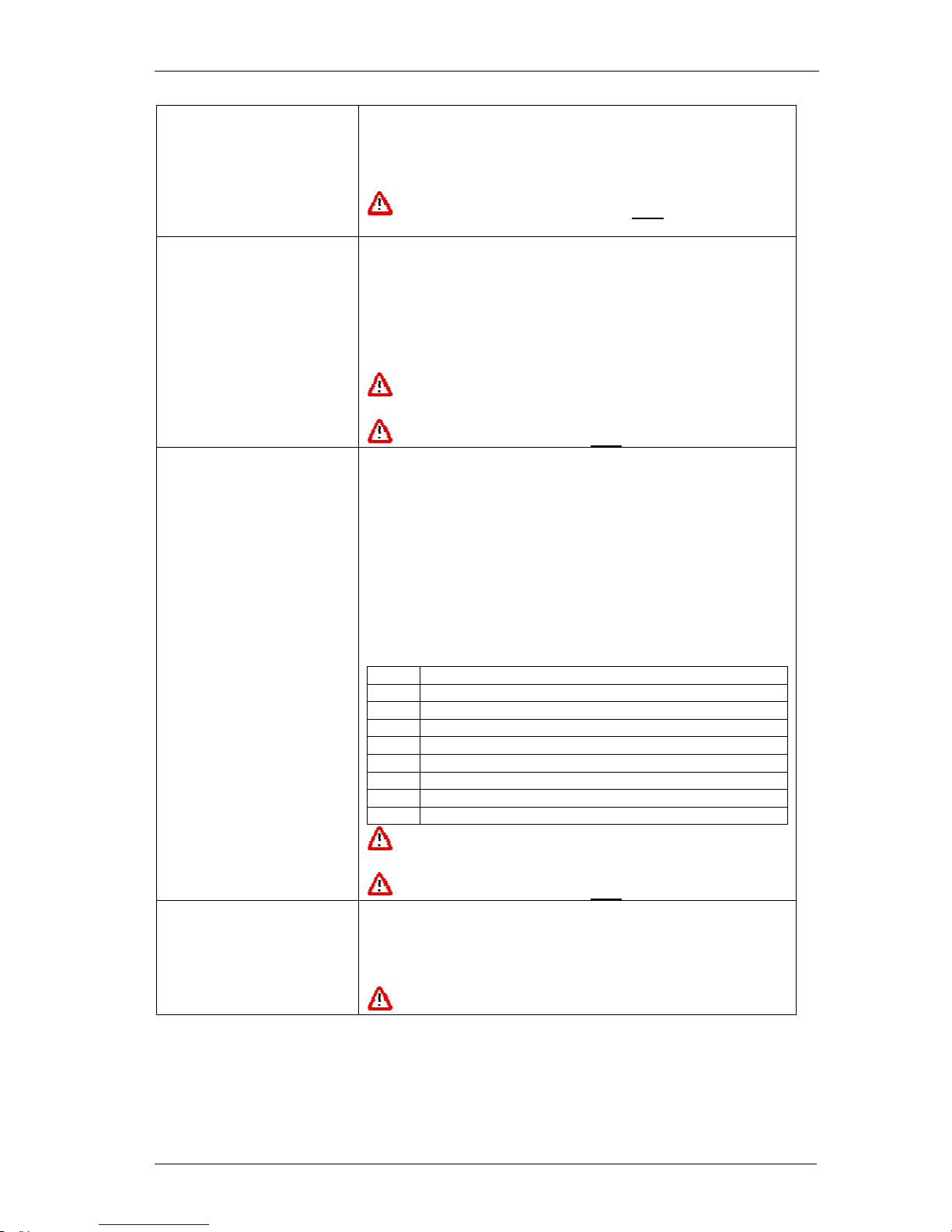
This command accepts a minimum of 2 and a maximum of 20
parameters, between 1 and 7 each.
Example:
*am321356 antennas 3, 2,1,3,5 and 6 in the given sequence.
Always enter command *sm1 after issuing an *am
command
*ta[_] Number of reading cycles per selected antenna.
This command accepts a minimum of 2 and a maximum of 20
parameters, between 1 and 9 each.
Example: if antennas 1, 2 and 3 have been selected with
*am123 and
*ta468
The reader will read four times on antenna 1, six times on
antenna 3 and eight times on antenna 3.
The number of parameters of *ta has to be always the same
as the number of parameters of *am
Always enter command *sm1 after issuing an *ta command
*oa[_] Digital output per selected antenna. This command accepts a
minimum of 2 and a maximum of 20 parameters, between 0 and
8 each.
Example: if antennas 1, 2 and 3 have been selected with
*am123 and
*oa678
The reader will activate output 6 when antenna 1 is selected,
output 7 when antenna 2 is selected and output 8 when antenna
3 is selected.
Output channels 0 to 8 correspond to the following open collector
outputs on the I/O connector:
0 No output selected
1 Internal relays selected
2 Digital output A1
3 Digital output A2
4 Digital output A3
5 Digital output A4
6 Digital output B1
7 Digital output B2
8 Digital output B3
The number of parameters of *oa has to be always the
same as the number of parameters of *am
Always enter command *sm1 after issuing an *oa command
*pg[_] This command applies specific tunnel antenna switching
algorithms.
*pg0: Cyclic
*pg1: Progressive
*pg2: Cyclic/Progressive
If you are not using a tunnel antenna, use parameter *pg0
Page 16

DATAMARS
R-IN 1300 MC User Manual – Rev 6.0
15 (50)
*o[_][_] Activate/deactivate single digital outputs.
*o0 Deactivate all outputs
*o10 Deactivate relais
*o11 Activate relais
*o20 Deactivate Digital output A1
*o21 Activate Digital output A1
*o30 Deactivate Digital output A2
*o31 Activate Digital output A2
*o40 Deactivate Digital output A3
*o41 Activate Digital output A3
*o50 Deactivate Digital output A4
*o51 Activate Digital output A4
*o60 Deactivate Digital output B1
*o61 Activate Digital output B1
*o70 Deactivate Digital output B2
*o71 Activate Digital output B2
*o80 Deactivate Digital output B3
*o81 Activate Digital output B3
4.6 USB SETTINGS
The USB-device can be used to emulate a serial-connection or a mass storage. Using the USBdevice like a “mass storage emulator”, it is possible to write the detected UIDs into a formatted file
(journal-file). The file format per default is CSV so that the journal-file can be opened with “Microsoft
Excel”.
The generic format of journal-file looks like this:
If antenna-index is not known If antenna-index is known
UID0 <line-separator>
UID1 <line-separator>
UID2 <line-separator>
UID3 <line-separator>
…
UID0 <field-separator> Antenna Index <line-separator>
UID0 <field-separator> Antenna Index <line-separator>
UID0 <field-separator> Antenna Index <line-separator>
UID0 <field-separator> Antenna Index <line-separator>
…
The customer can configure the “field-separator”, the “line-separator” and the extension of the journalfile.
Note: Refer to chapter 6.2 to get information on how to retrieve and handle the journal-file
*us[_] USB usage:
*us0 USB disabled
*us1 USB serial emulation
*us2 USB mass storage emulation
*jf[_] Journal-file format:
*jf0 csv-format (default)
*jf1 customized format
*fs[_] Field-separator:
Valid values: sequences of characters (max. length = 10 )
To specify “Carriage-Return”, type “\r”
To specify “New-Line”, type “\n”
Page 17

DATAMARS
R-IN 1300 MC User Manual – Rev 6.0
16 (50)
To specify “Horizontal-Tab”, type “\t”
*ls[_] Line-separator:
Valid values: sequences of characters (max. length = 10 )
To specify “Carriage-Return”, type “\r”
To specify “New-Line”, type “\n”
To specify “Horizontal-Tab”, type “\t”
*fe[_] Journal-file extension:
Valid values: sequences of characters (max. length = 5 )
4.7 MEMORY PEN SETTINGS
*mp[_] Memory-pen mode:
*mp0 Memory-pen mode off
*mp1 Memory-pen mode on
When memory-pen mode is on, read UIDs are written in the
memory-pen into a file named “inventory.txt (more details in
chapter 7)
*td Show current time and date (more details in chapter 7)
*td[___...___] Set current time and date
Format: *td-DD-MM-YYYY-hh-mm-ss
Ex: *td-03-09-2010-15-05-30 ( 3rd September 2010 15:05:30)
Page 18
DATAMARS
R-IN 1300 MC User Manual – Rev 6.0
17 (50)
5 OPERATION WITH GRAPHICAL USER INTERFACE (GUI)
The R-IN1300 MID can be operated through 2 kinds of GUIs:
• The http GUI (Java applet) via the Ethernet port which can be used through a standard
browser like MS Internet Explorer or Firefox.
• The Datamars Reader Configurator, a Java application which communicate to the reader
though the RS-232 serial port based on the terminal interface protocol (see sections 4)
5.1 CONNECTING WITH ETHERNET (RECOMMENDED)
The reader “R-IN1300 MC” can be connected to the LAN just like a PC (Ethernet cable & RJ-45
connectors).
A direct Ethernet connection between a PC and “R-IN1300 MC” reader is also possible, with an
Ethernet Cross Cable (supplied together with the reader). Refer to Appendix A for more details on
how to do this.
In both cases the reader “R-IN1300 MC” must be provided with a correct IP-Address (DHCP is not
yet available. Thus the reader is not yet able to get its IP-address automatically).
To provide the “R-IN1300 MC” reader with an IP-address, it is recommended to configure it with the
supplied cross cable (or RS-232 interface), at least for the first time, in order to avoid IP conflicts in
your network. See appendix A for more details on how to connect your reader with a cross cable.
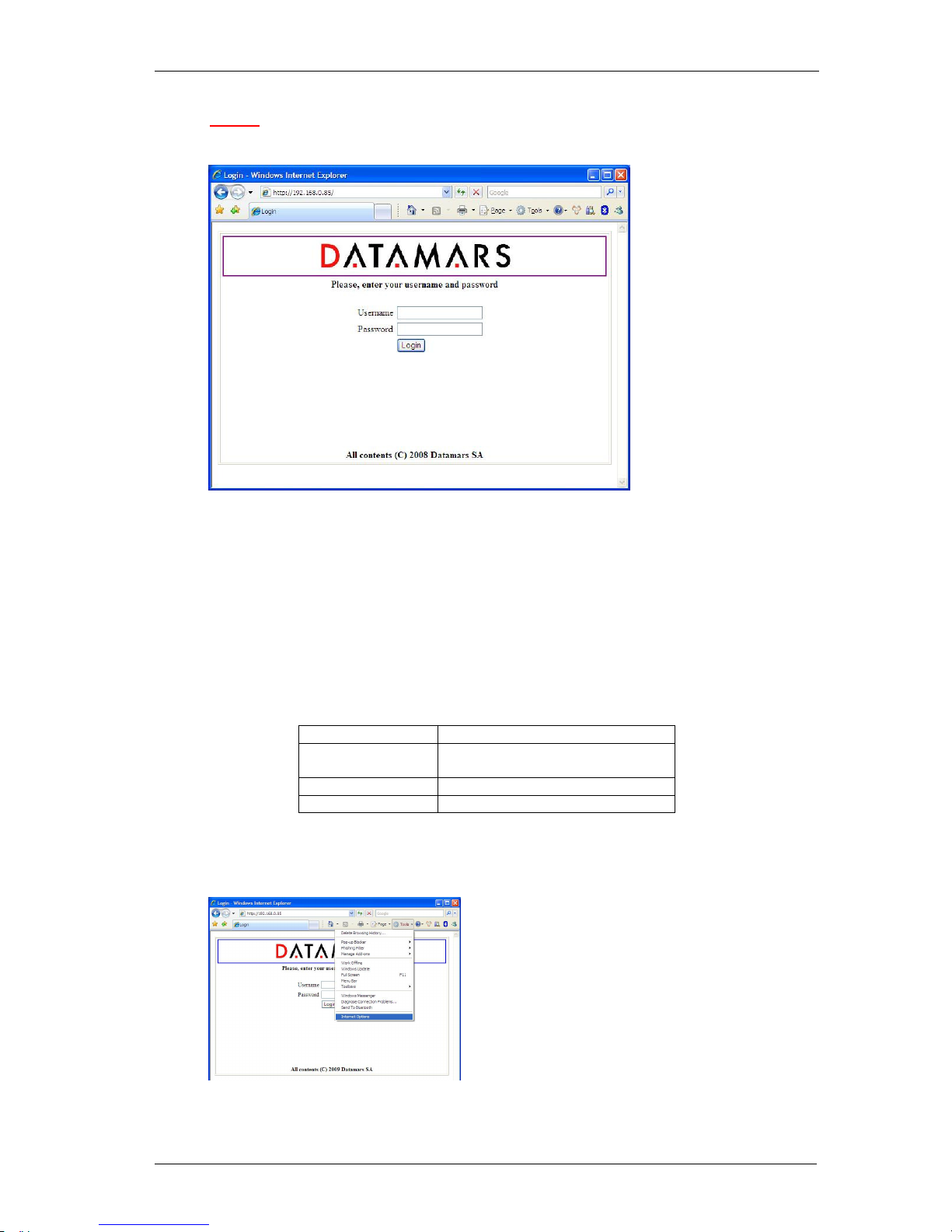
When the reader has its own IP-Address on the LAN (or with cross cable), you can go to login-page of
the reader and have access to the configuration-, monitoring- and administrator- tools. To access the
login-page, open a web browser (Internet Explorer, Firefox, etc.) and type http://192.168.0.85
(or the
IP that you have configured) in the address bar.
5.2 CONNECTING WITH THE COM (RS-232)
The reader “R-IN 1300 MID” can be connected to a PC with a serial connection and operated through
the Datamars Reader Configuration
Page 19

DATAMARS
R-IN 1300 MC User Manual – Rev 6.0
18 (50)
The Datamars Reader Configuration is a Java application which makes use of the command line
intereface through the RS-232 interface. The application need to be installed on the PC from the the
CD-ROM supplied with the reader. The installation will start automatically when the disk is inserted in
the PC, just follow the on screen instructions.
In case the installation does not start, open the CD and double click on “install”.
At the end of the installation procedure the necessary software will be found in the Start menu.
5.3 GENERAL CONSIDERATIONS
5.3.1 THIRD PARTY INTERFACE
The “R-IN1300 MC” Reader always listens to incoming TCP/IP connections on port 1026 (TCP/IP
socket).
Using this dedicated TCP/IP socket, third party applications can connect to, exchange data with,
configure and monitor the “R-IN1300 MC” reader.
Refer to the “R-IN 1300 TCP/IP Dedicated Protocol” (UM001031) for a detailed description of the
whole communication protocol and syntax.
5.3.2 HUMAN INTERFACE
The interface (graphical program running on the browser) shows the configuration of the reader “RIN1300 MC” as a tabbed panel. Each panel groups logically tied parameters.
The SAVE, DEFAULT and CANCEL buttons act locally on the parameters of the current active tab.
The REFRESH button acts on the whole configuration (on all tabs).
To save the configured settings shown in the tab, press the SAVE button.
To restore the factory default settings of the current tab, press the DEFAULT button.
To undo changes done on the current tab, press the CANCEL button.
To view the actual parameters of the reader on all tabs, press the REFRESH button.
The parameters shown in the tabs may depend on each other. The selection of some options could
make some parameters “meaningless” in this context. In such cases relevant parameters are shown
normally while “meaningless” parameters are masked/disabled.
All parameters described in this manual refer to the High Frequency “R-IN1300 MC” with exception of
the parameters contained in the “Combo Setup Panel” and “Advanced Setup Panel” which refer to the
“Low Frequency Reader R-IN 7500”.
The graphical application requires a Java2 or Java5 plug-in. If the requested plug-in is already
installed on your PC, you are immediately able to run the application. Otherwise the system will try to
connect to the WWW to download the plug-in. In this case, follow every installation step always
accepting the defaults suggested by the system.
Page 20
DATAMARS
R-IN 1300 MC User Manual – Rev 6.0
19 (50)
5.3.3 LOGIN
The interface running on the browser permits access to users only via login (user name & password):
attempts to join the configuration- and monitoring tools directly via bookmarks are prevented from the
system.
A user trying to connect while the system is already occupied (i.e. by another user having logged in
before) gets access in read-only mode thus preventing the configuration from being modified at the
same time by more users.
When the user closes the browser, the system becomes free, allowing other users to login and get
read-write mode. The administrator (only she/he) can force the system to disconnect users when the
system is kept busy too long. The default accounts are defined as follows, passwords can be
changed.
User Names Default Passwords
admin Admin (read, modify and
administrative rights )
user1 1234 (read and modify rights)
user2 1234 (read-only rights)
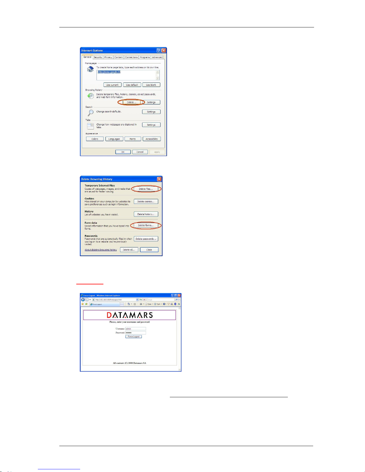
Please note: in case of problems while connecting to the reader via browser, try to clear the cache of
the browser.
1) First step: select “Tools” and then “Internet Options”
2) Second step: Press the button *Delete…”
Page 21
DATAMARS
R-IN 1300 MC User Manual – Rev 6.0
20 (50)
3) Third step: press the button “Delete”
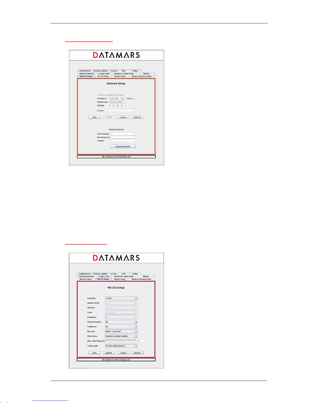
5.4 LOGOUT
The “administrator” can disconnect every session to the reader in case of suspect use of the GUI (i.e.
a user is logged in for too much time monopolizing the system).
The “administrator” must go to the URL: http://ip-address-of-the-reader/forceLogout.html and give
her/his user password.
Page 22
DATAMARS
R-IN 1300 MC User Manual – Rev 6.0
21 (50)
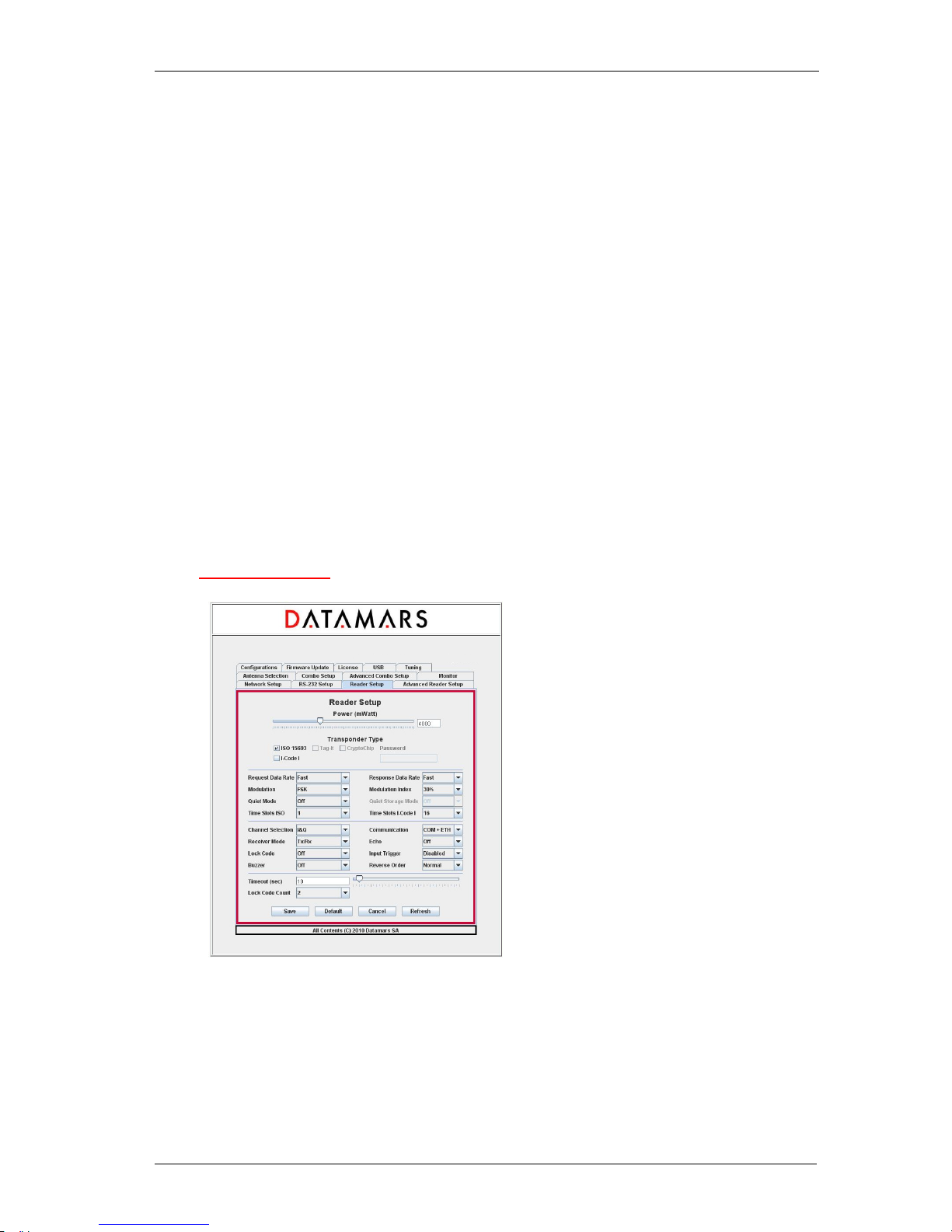
5.5 NETWORK SETUP
The “Network Setup” tab allows users to specify network parameters: IP address, sub-mask and
default gateway. The IP address can be a fixed IP-Address (in this case the ip-address and port must
be specified) or a dynamic one (DHCP) not available yet. After having changed any network
parameters, the browser must be closed and a new login must be done using the new network setup
of the reader.
The “Location” field specifies the place where the reader has been put. From this tab it is also
possible to change the password of the current user. The current password must be specified, the
new password must be confirmed (specified twice). Pressing the CHANGE PASSWORD button, the
request is submitted to the reader and the user is told about the success/failure of the sent command.
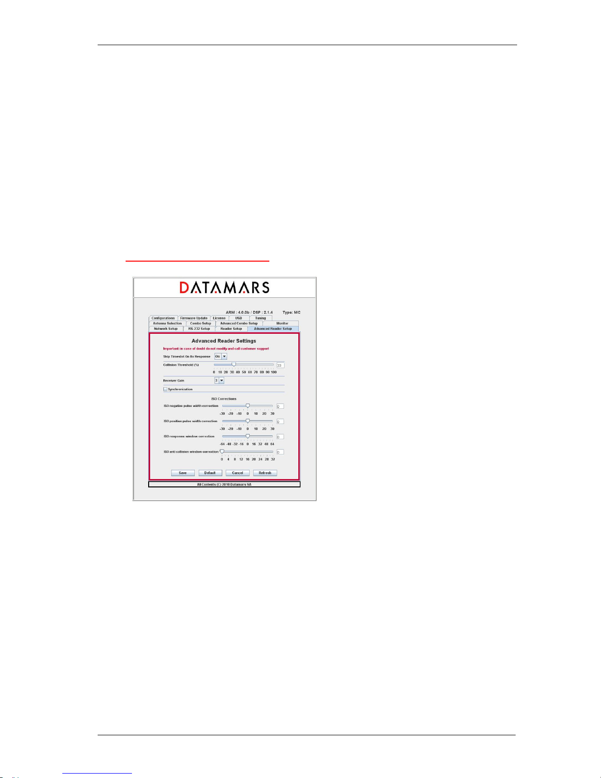
5.6 RS 232 SETUP
ARM: 4.0.0 / DSP 2.1.4 Type
: MC
ARM: 4.0.0 / DSP 2.1.4 Type: MC
Page 23
DATAMARS
R-IN 1300 MC User Manual – Rev 6.0
22 (50)
The “RS-232 Setup” allows users to specify the properties of the serial connection.
The “Baud Rate” and “New Line” fields are implemented on the interface (PC or browser) as well as
on the reader.
The fields “Number of bits”, “Stop bits”, “Parity”, “Handshake” are implemented on the interface but
not yet on the reader. Changes done on these fields do not yet affect the system behaviour.
The “Remove Header” field informs the reader that expected responses must contain only essential
information (explanations, warnings and miscellaneous information must be cut off).
The “Continuous” field enables/disables the continuous-reading mode. If this property is enabled,
inventory-cycles are automatically repeated otherwise only one cycle is done.
The “Stand Alone” field has following meanings:
Stand Alone Mode Disabled: after the reader has been turned on, it waits for the start-reading
command to come. Until this moment, it remains in a not-reading state.
Stand Alone Mode Enabled (Detect): at power on the reader starts reading automatically and sends
the found UIDs after each inventory cycle.
The “Inter Code Delay” field specifies how much time (in sec/100) must be awaited between the
sending of two subsequent UIDs.
The “Code Length” field specifies the length and for
mat of the sent UIDs.
5.7 READER SETUP
The “ReaderSetup” tab allows users to specify overall properties of the reader.
It is possible to specify:
the antenna power:
• 0 mW – 12 000 mW (1000 mW = 1 W; 2000 mW = 2 W; etc. )
the technologies of the transponders being used:
• ISO-15693
• I-Code I
ARM: 4.0.0 / DSP 2.1.4 Type: MC
Page 24

DATAMARS
R-IN 1300 MC User Manual – Rev 6.0
23 (50)
the ISO-15693 properties (see corresponding ISO-specification):
• Request/Response Data Rate
• Modulation Type/ Modulation Index
• Quiet Mode /Quiet Storage
• Time Slots ISO/I-Code-1
The “Channel Selection” field specifies which channel is selected between I-Channel and I/QChannel. Choose I-Channel with 3.5 m cables for best performance.
The “Receiver Mode” field allows selecting “Rx/Tx” or “Rx Only”. Select “Rx/Tx” if you have a single
antenna or “Rx Only” if you want to use a separate antenna connected to the Rx connector.
Caution: the Rx Channel is very sensitive.
The “Lock Code” field specifies a particular behaviour of the reader:
Details for LockCode 0: Disabled.
Details for LockCode 1 (on detection): Any transponder is read just once. To read a transponder
again, another one must be read first.
Details for LockCode 2 (on timeout): The transponder is first visible when entering the magnetic
field the first time and it is detected only once without regard to the time spent in the field. A chip
having left the magnetic field can be read again only having spent an amount of time T outside of it. If
the time spent outside the magnetic field is less than T, the chip cannot be detected.
Details for LockCode 3 (on counter): The transponder is visible only once when entering the
magnetic field for the first time. Afterward, to be visible again, it must leave the magnetic field area
and wait outside until at least N different transponders have been read (N is the number specified by
the field “Lock Code Count”).
Note: LockCode 1 (on detection) is the same as LockCode 3 (on counter) with N = 1.
The “Communication” field specifies on which output channels the reader must write the found UIDs.
The “Echo” field specifies whether the user-input written onto the terminal (RS-232) must be shown
on the screen or not.
The “Input Trigger” field specifies a particular behaviour of the reader:
Input-Trigger 0: Disabled
Input-Trigger 1:
IN1
When IN1 is high level, it’s possible to read the transponder.
t1 min 50 ms.
Input-Trigger 2:
IN2
The rising edge of IN1 starts reading
The rising edge of IN2 stops reading
IN1
Page 25
DATAMARS
R-IN 1300 MC User Manual – Rev 6.0
24 (50)
t2 min 5 ms
t3 min 100 ms
Input-Trigger 3: like Input-Trigger 1 with reversed edge-logic
Input-Trigger 4: like Input-Trigger 2 with reversed edge-logic
The “Buzzer” field specifies a particular behaviour of the buzzer connected to the I/O connector:
Buzzer Off: Buzzer disabled
Buzzer On Detection: Buzzer enabled when a transponders is detected.
Buzzer Off: Buzzer enabled when the transmission is ON.
The “Reverse Order” field specifies the representation of the UIDs:
Reverse Order Off : UIDs are not reversed
Reverse Order On : UIDs are reversed
5.8 ADVANCED READER SETUP
This Tab contains fields affecting the performance of the reader depending on the architecture of the
installation.
Those configuration-fields are reserved for technical purposes only and should NEVER be changed
by customers. For more information please contact “Datamars – Support Team”.
Page 26
DATAMARS
R-IN 1300 MC User Manual – Rev 6.0
25 (50)
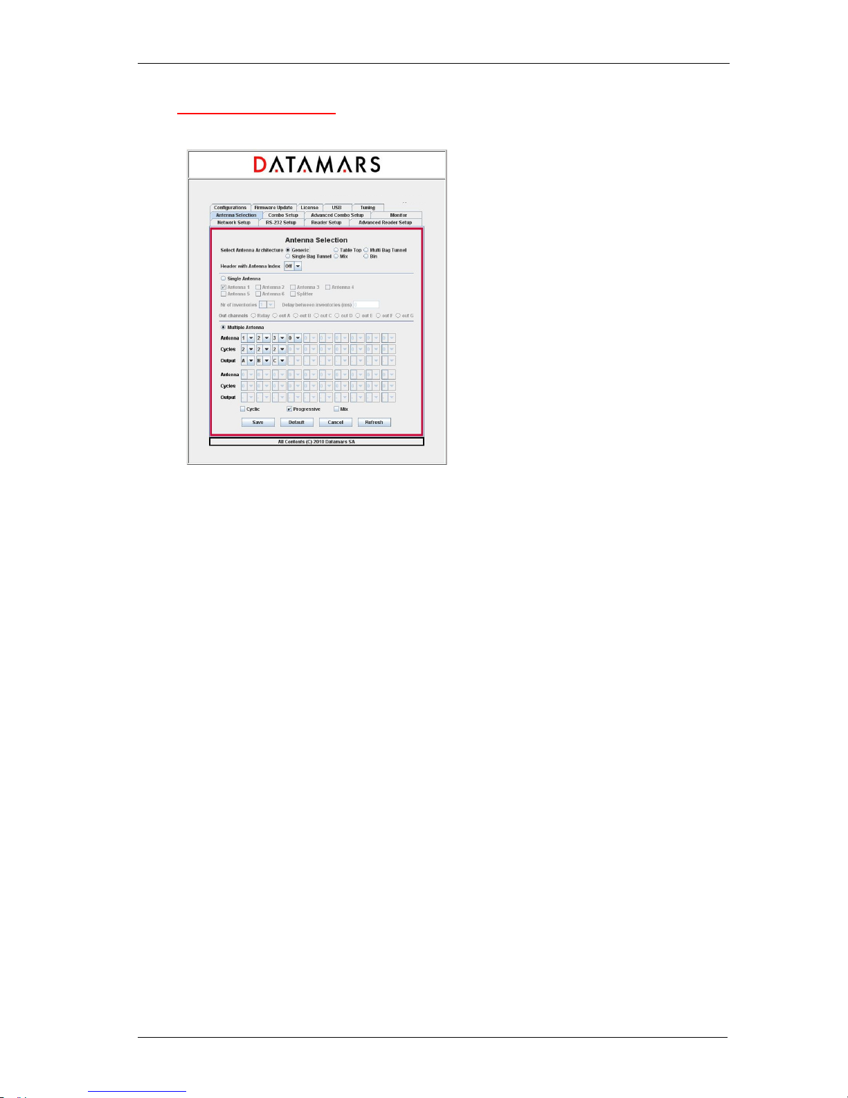
5.9 ANTENNA SELECTION
The “Antenna Selection” tab allows users to specify which kind of antennas are connected to the
reader and which output channels are active (just by clicking on the corresponding Radio-Buttons).
The “Antenna Architecture” field allows the choice of Table Top-, Multi Bag Tunnel-, Single Bag
Tunnel-, Mix-, Bin- and Generic- Antenna.
If the Table Top-Antenna architecture is selected together with non-continuous mode, the “Nr of
inventories” field specifies how many inventories must be done while the “Delay between
inventories” is the time between two consecutive inventories (in ms).
In such configuration, after read-command is received, the reader performs as many inventories as
specified waiting in between for the specified delayed to expire. Then the system stops reading.
If the configured antenna architecture is any other than “Table-Top – non continuous”, those fields do
not have any influence on the behaviour of the reader.
If you select “Generic Antenna” you also have to specify its architecture (single or multiple) and other
working parameters. All other kinds of antennas are treated by the system assigning them default
behaviours and configurations. In this way, the user does not need deep knowledge about technical
aspects of the selected antenna.
NB: The hardware of Multi Bag Tunnel- and Single Bag Tunnel- is the same. The selection between
these two options only activates two different default configurations specially suited for best
performance.
Multi Bag Tunnel: Set this parameter if your Tunnel antenna must be able to process more than one
bag at the same time.
Single Bag Tunnel: Set this parameter if your Tunnel antenna must process only one bag at a time.
In this case you need to wait to put a new until the previous one is out.
Mix: Like “Single Bag Tunnel” but suited for reading a small number of tags (less than 10 tags per
bag)
NB: If you have antennas from Datamars you just need to select the proper type and the system will
do the rest for you.
ARM: 4.0.0 / DSP 2.1.4 Type: MC
Page 27

DATAMARS
R-IN 1300 MC User Manual – Rev 6.0
26 (50)
How to configure a “Generic Multiple Antenna”:
If “Generic & Multiple Antenna” is selected, the user must configure the reading sequence (antenna
seq.), the number of inventory cycles and select the output for each step.
To do that, the user is guided by the system preventing inconsistent input values.
To specify an antenna within the antenna-sequence, use the corresponding “Antenna Combo-Box”
and select 1, 2, 3, 4, 5, 6, S (Splitter).
To specify the number of inventory cycles within the cycles-sequence, use the corresponding “Cycles
Combo-Box” and select 1, 2, 3, 4, 5, 6, 7, 8 or 9.
To specify a digital output to be activated within the output-sequence, use the corresponding “Output
Combo-Box” and select – (none), R (receiver channel), A, B, C, D, E, F or G.
To delete a couple made of “antenna-cycles”, use either the corresponding “Antenna Combo-Box” (in
the antenna-sequence) or the corresponding “Cycles Combo-Box” (in the cycles-sequence) and
select 0.
To insert a new couple made of “antenna-cycles” in the middle of the sequence, select the “Antenna
Combo-Box” at the position where the insertion is intended to be done and select I. A new couple is
inserted and the following elements of the sequence are shifted.
To append a new couple made of “antenna-cycles”, use the “Antenna Combo-Box” at the very end of
the sequence and select 1, 2, 3, 4, 5, 6, S (Splitter).
Header with Antenna Index: if this option is set, the UID of the tag is preceded by the index of the
antenna having detected it.
Page 28
DATAMARS
R-IN 1300 MC User Manual – Rev 6.0
27 (50)
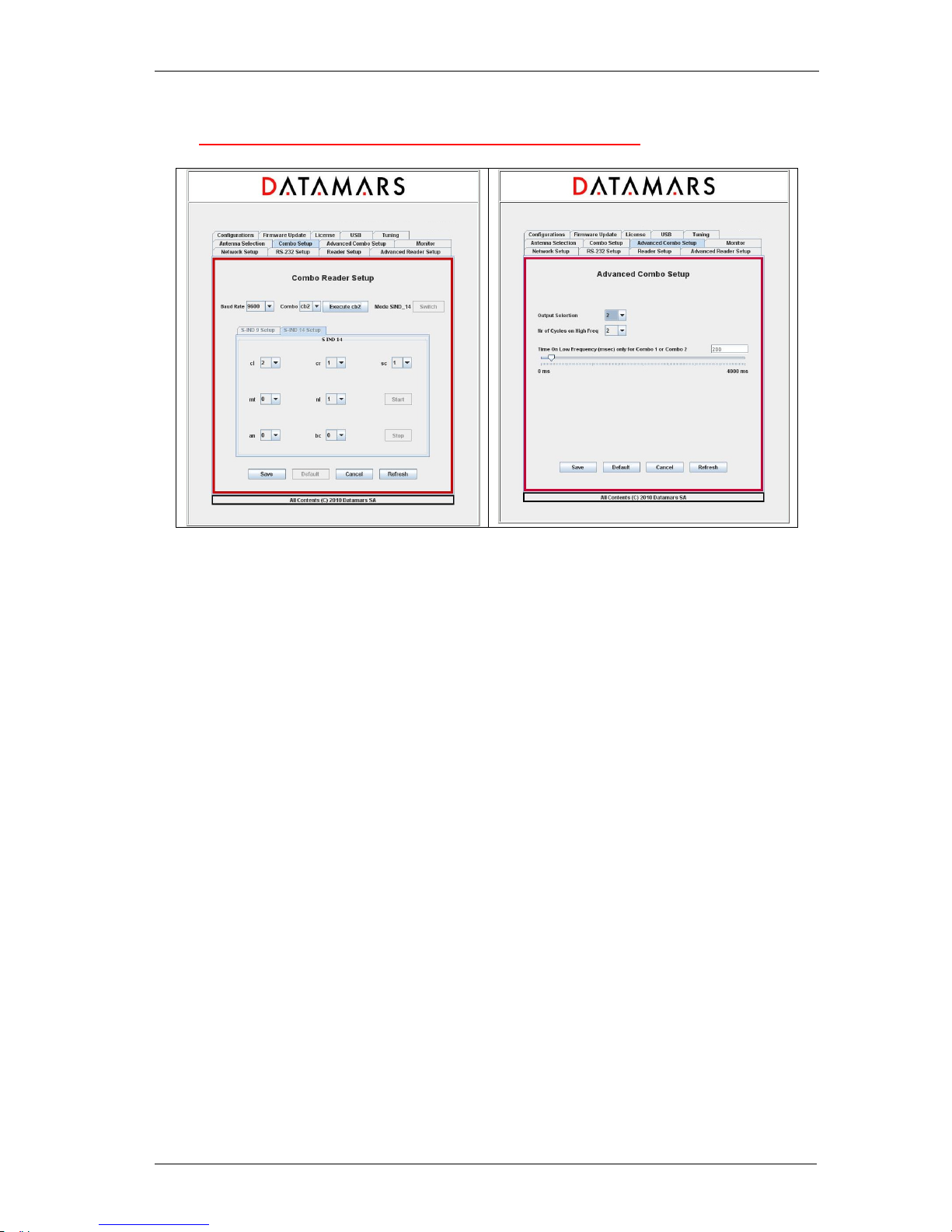
5.10 COMBO READER SETUP – ADVANCED COMBO SETUP
The “Combo Reader Setup” and “Advanced Combo Reader Setup” allow users to specify the
properties of the “low frequency” reader and to detect its current working state. The “Baud Rate”
field refers to the baud rate of the “low frequency” reader.
The “Combo Type” field allows users to modify the working-mode of the “low-frequency” reader. Just
select the desired mode and the corresponding command is immediately sent to the “low frequency”
reader (no need to press the SAVE button). Warning: this operation may take some seconds.
The “low-frequency” reader can be switched from s-ind9 to s-ind14 or vice versa (see low frequency
manual) by pressing the “SWITCH”-button. If the current working state of the” low-frequency” reader
does not allow this operation, the “SWITCH”-button is disabled and cannot be pressed. Depending on
the current “s-ind mode”, a set of configuration parameters is displayed onto the tab. To know the
meaning of these fields, read the R-IN 7500 manual.
ARM: 4.0.0 / DSP 2.1.4 Type: MC
ARM: 4.0.0 / DSP 2.1.4 Type: MC
Page 29
DATAMARS
R-IN 1300 MC User Manual – Rev 6.0
28 (50)
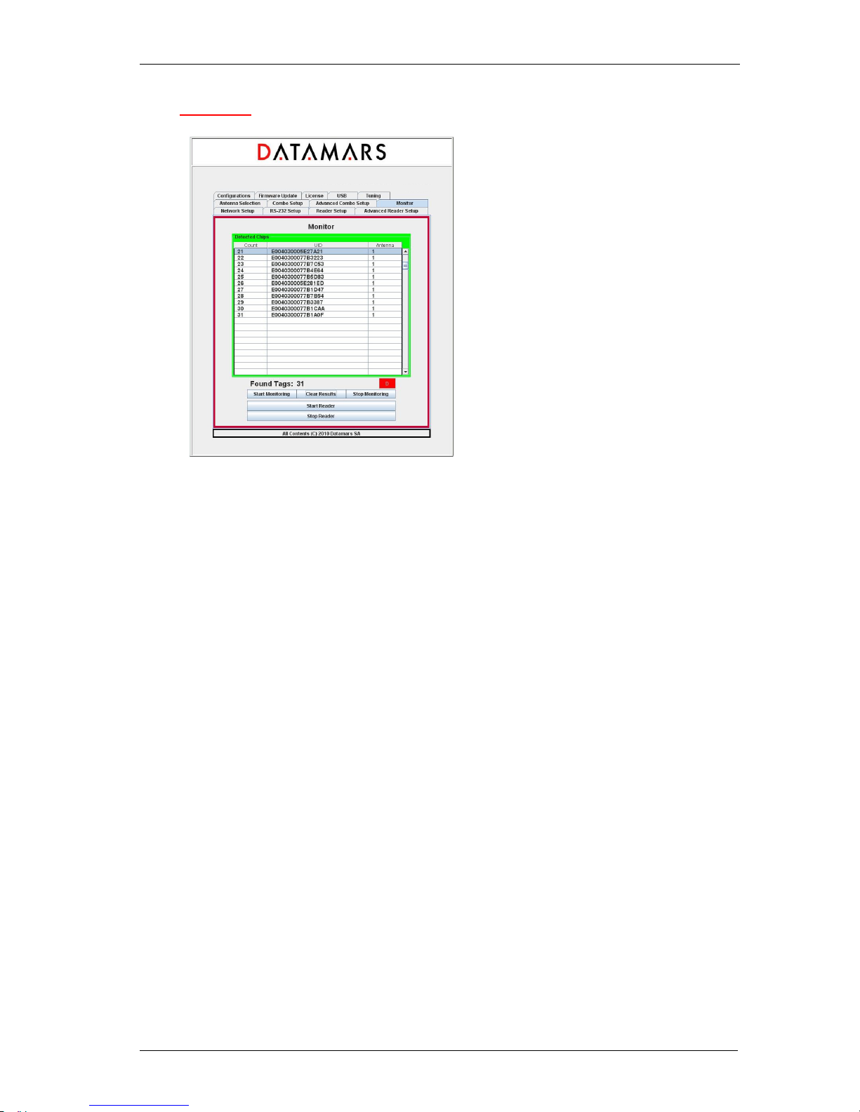
5.11 MONITOR
The monitor tab is used for verifying whether the reader is active or not.
The “Start Reader” button makes the reader start its inventory cycles.
The “Stop Reader” button makes the reader suspend its reading process.
The “Start Monitoring” button permits to display the UIDs of the chips found by the reader.
The “Clear Result” button clears the UIDs display.
The “Stop Monitoring” button stops the display.
The led “D” (detection) is green if the reader sends UIDs, red otherwise.
PLEASE NOTE:
UIDs are displayed only once: duplicated UIDs are not displayed again! This could give the
impression that the reader does not work correctly but this is NOT true. Please, in this case press the
“Clear Result” button. If you press the “Stop Reader” button, the reader stops its reading process.
Please click this button only if you are sure that the suspension of the reader activities does not cause
the loss of important data.
ARM: 4.0.0 / DSP 2.1.
4 Type: MC
Page 30
DATAMARS
R-IN 1300 MC User Manual – Rev 6.0
29 (50)
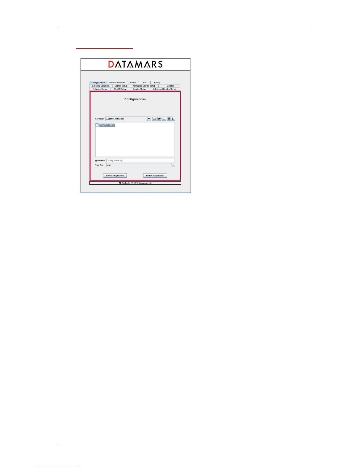
5.12 CONFIGURATIONS
The “R-IN1300 MC” reader offers a tool giving the user the possibility to save and/or reload
configuration files. First of all, select the tab named "Configurations". To save the currently active
configuration, select the destination folder using the navigator, write the destination file name in the
related input field and then press the button "Save Configuration".
To load a previously saved configuration, select the folder and file using the navigator and then press
the button "Load Configuration".
ARM: 4.0.0 / DSP 2.1.4 Type: MC
Page 31
DATAMARS
R-IN 1300 MC User Manual – Rev 6.0
30 (50)
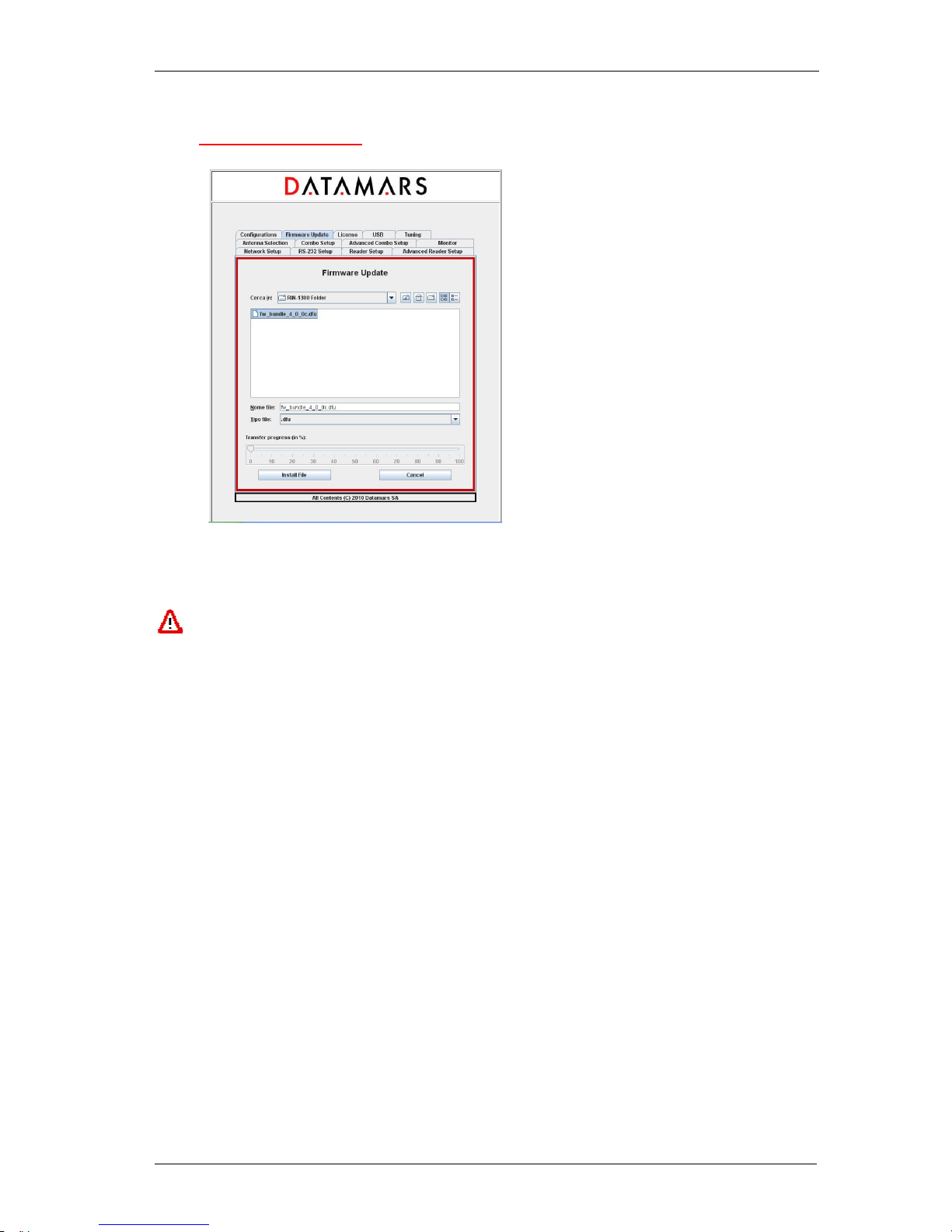
5.13 FIRMWARE UPDATE
The GUI-version running on the browser offers the user a tool to update the software of the “R-IN1300
MC” reader.
Firmware version 4.0.0 and later ones ARE NOT COMPATIBLE with older ones: FW3.5.5 or
previous one cannot be updated to FW4.0.0 through the automatic procedure “Firmware
Update”. Likewise, FW4.0.0 or later cannot be downgraded to an older version. Trying to force
incompatible firmware upgrade would prevent the reader to start and Datamars customer
support would be needed to restore its functionality.
First of all select the tab named "Firmware Update" and select the file containing the new software
(delivered by Datamars SA) using the navigator and then click the “Install File” button. The new
software is now transferred (copied) from the PC to the reader. A slider tells about the transferring
process status.
If the transferring-process hangs or if the user notices that a wrong file has been transferred, the user
can cancel the operation and remove the transferred file by clicking the “Cancel” button.
When the whole file has been completely transferred onto the reader, the user is prompted by a popup window asking to proceed with installation and activation of the new firmware. The user can
confirm or cancel the operation.
If the user decides to continue and to activate the new software, she/he MUST wait until the whole
installation process is terminated. During the process the ‘HF’ Led blinks and it turns off ONLY when
everything has been completed. One the HF Led is off, the reader MUST be switched OFF and
RESTARTED to load the new firmware.
Note: The installation of the new software can require a couple of minutes: during such period the
reader MUST NOT BE TURNED OFF.
Note: While performing the firmware-update, the reader disables the Ethernet connection and the
message “Connection lost” appears on the GUI.
ARM: 4.0.0 / DSP 2.1.4 Type: MC
Page 32
DATAMARS
R-IN 1300 MC User Manual – Rev 6.0
31 (50)
Note: To preserve custom parameters configuration, before starting the firmware update, save back
up configuration file as described in session 5.12. Once the firmware update has been completed,
load the configuration in order to restore custom parameters.
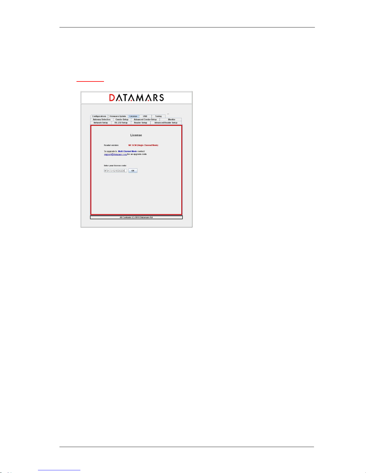
5.14 LICENSE
The “License” tab allows users to enter the reader-specific license code.
Click the link “[email protected]” to request the license code contacting Datamars.
Enter the license code delivered by Datamars into the input-field and click OK.
ARM: 4.0.0 / DSP 2.1.4 Type: MC
SCM
Page 33
DATAMARS
R-IN 1300 MC User Manual – Rev 6.0
32 (50)
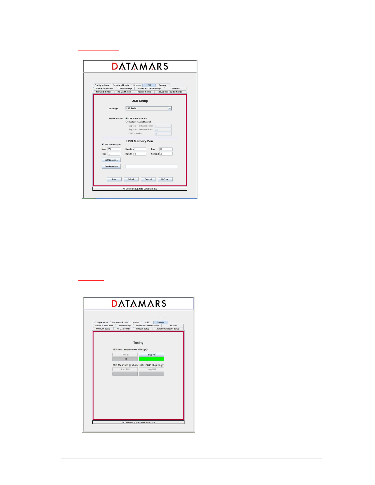
5.15 USB SETUP
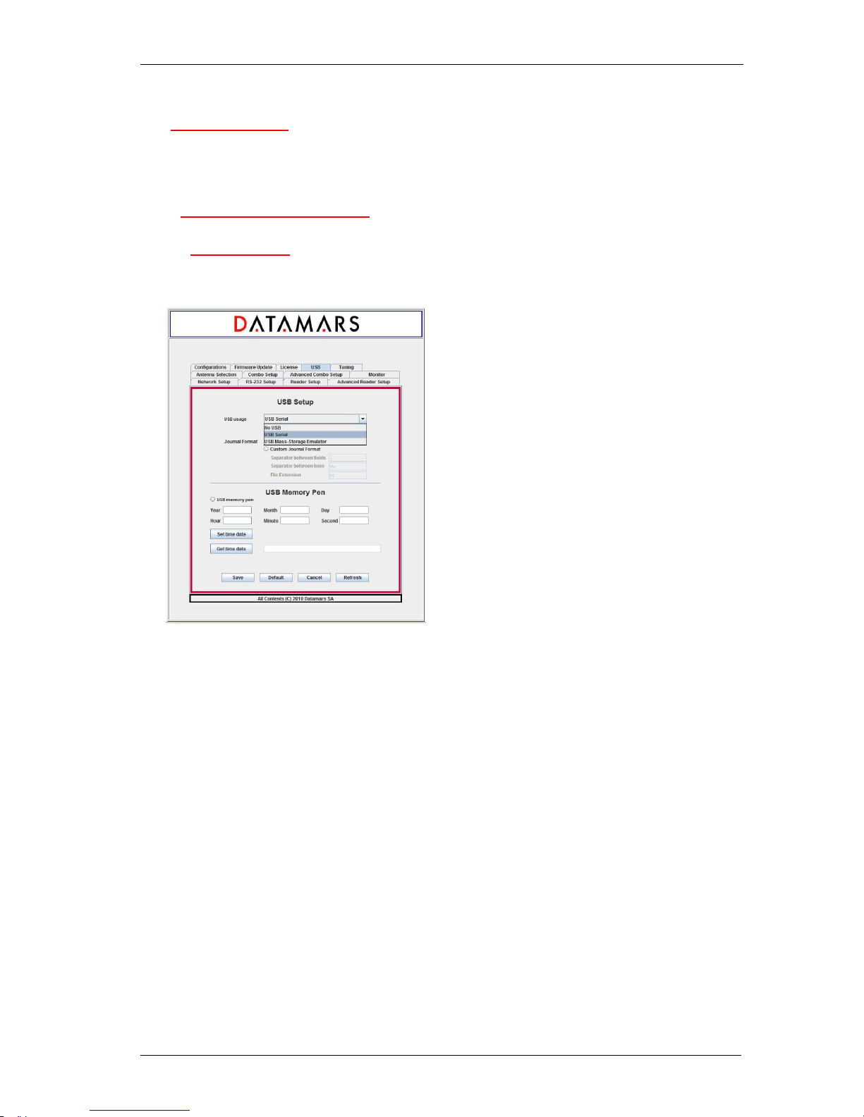
Select from the “USB usage” combo-box the desired functionality (serial disabled, serial emulation,
mass-storage emulation). If “USB-Mass-storage Emulation” is chosen, the UIDs are written into a file
(journal-file) whose format is configurable (CSV or custom).
Refer to chapter 6 for an exhaustive explanation about installing, using and manipulating the USBserial and mass-storage emulation.
Refer to chapter 7 for an exhaustive explanation about the usage of the USB-Memory-Pen.
5.16 TUNING
ARM: 4.0.0 / DSP 2.1.4 Type: MC
ARM: 4.0.0 / DSP 2.1.4 Type: MC
Page 34

DATAMARS
R-IN 1300 MC User Manual – Rev 6.0
33 (50)
This functionality is reserved for technical purposes and it should be needed by qualified technician
only. For more information refer to chapter 8.
5.17 SYSTEM REQUIREMENTS
OS: MS Windows 98 or higher, MAC OS X, Linux
Software: Java 2 Runtime Environment v. 1.4 or higher.
Hardware: 32 MB of RAM, 50MB of free hard disk space.
Page 35
DATAMARS
R-IN 1300 MC User Manual – Rev 6.0
34 (50)
6 USB-DEVICE
This chapter describes how to correctly handle the USB-Device functionalities. Please, read this
chapter carefully and follow strictly the described manipulations.
6.1 USB SERIAL EMULATION
6.1.1 FIRST USAGE
• Select the “USB Serial” functionality with *us1” (on terminal) or via GUI
• Plug in the USB-cable and connect your PC with the “R-IN1300 MC Advanced” (USB-cable
AB)
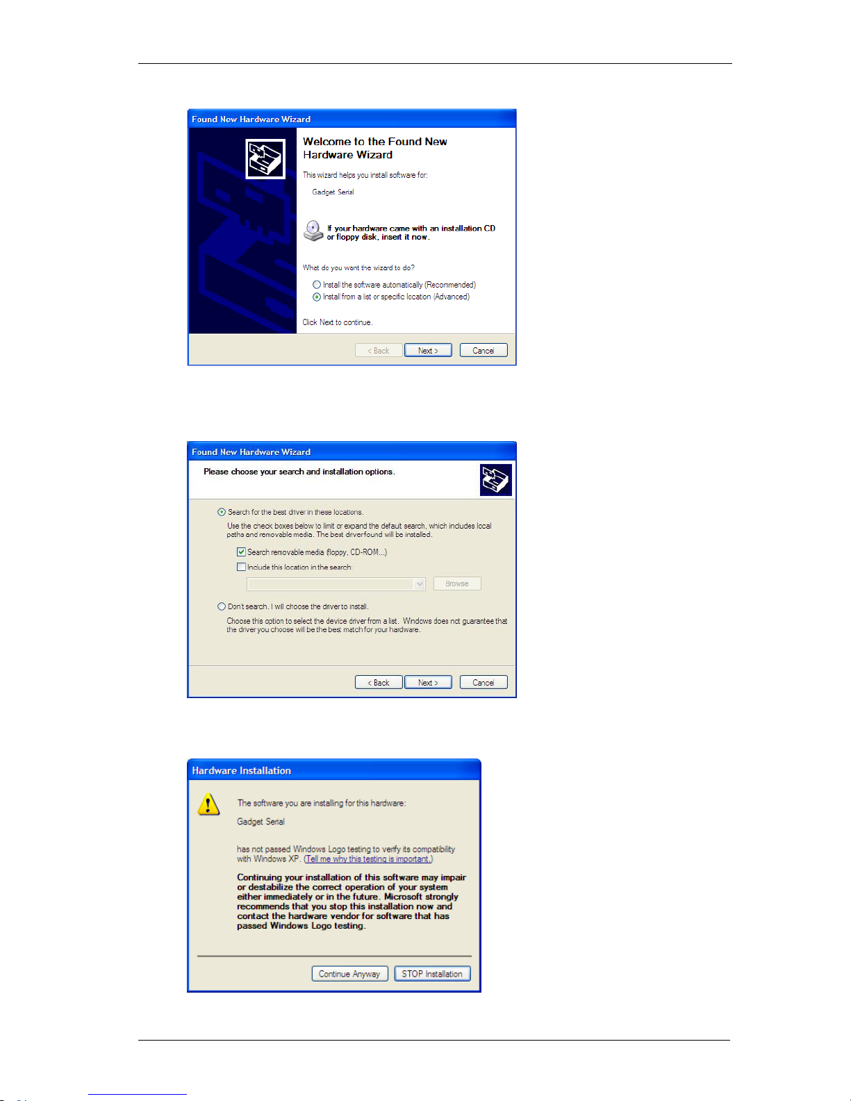
• The “Found New Hardware Wizard”-window appears automatically.
Insert the delivered CD-Rom into the PC and select “Install from a list or specific location
(Advanced)” and click “Next”
ARM: 4.0.0 / DS
P 2.1.4 Type: MC
Page 36
DATAMARS
R-IN 1300 MC User Manual – Rev 6.0
35 (50)
• Select “Search the best driver in these locations” and “Search removable media(floppy,
CD-ROM…)” and then click Next
• Answer “Continue Anyway”
Page 37
DATAMARS
R-IN 1300 MC User Manual – Rev 6.0
36 (50)
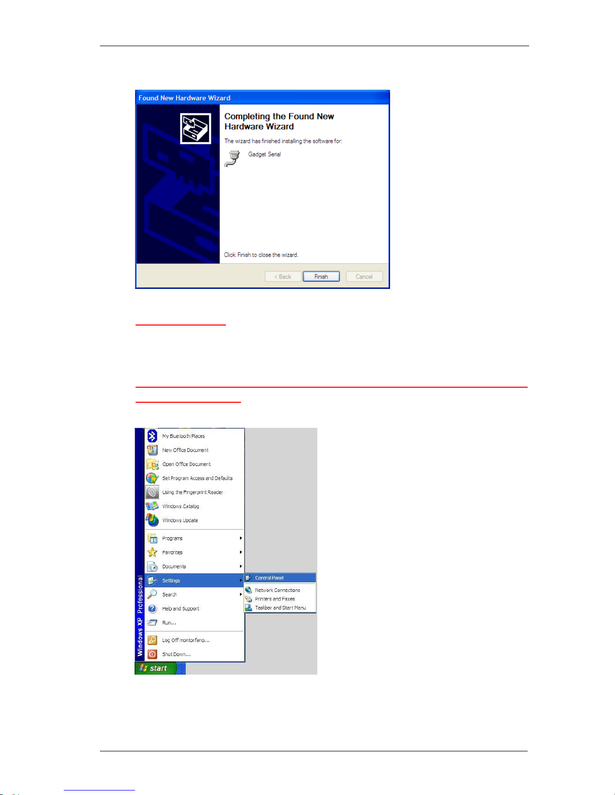
• Click “Finish”:
6.1.2 FURTHER USAGE
For further usage there is no need to install the USB Serial Drivers. Just specify that you intend to
use the USB-Serial-Emulation and plug the USB-cable in.
6.1.3 HOW TO DISCOVER WHICH COM-PORT CORRESPONDS TO THE USBSERIAL-EMULATION
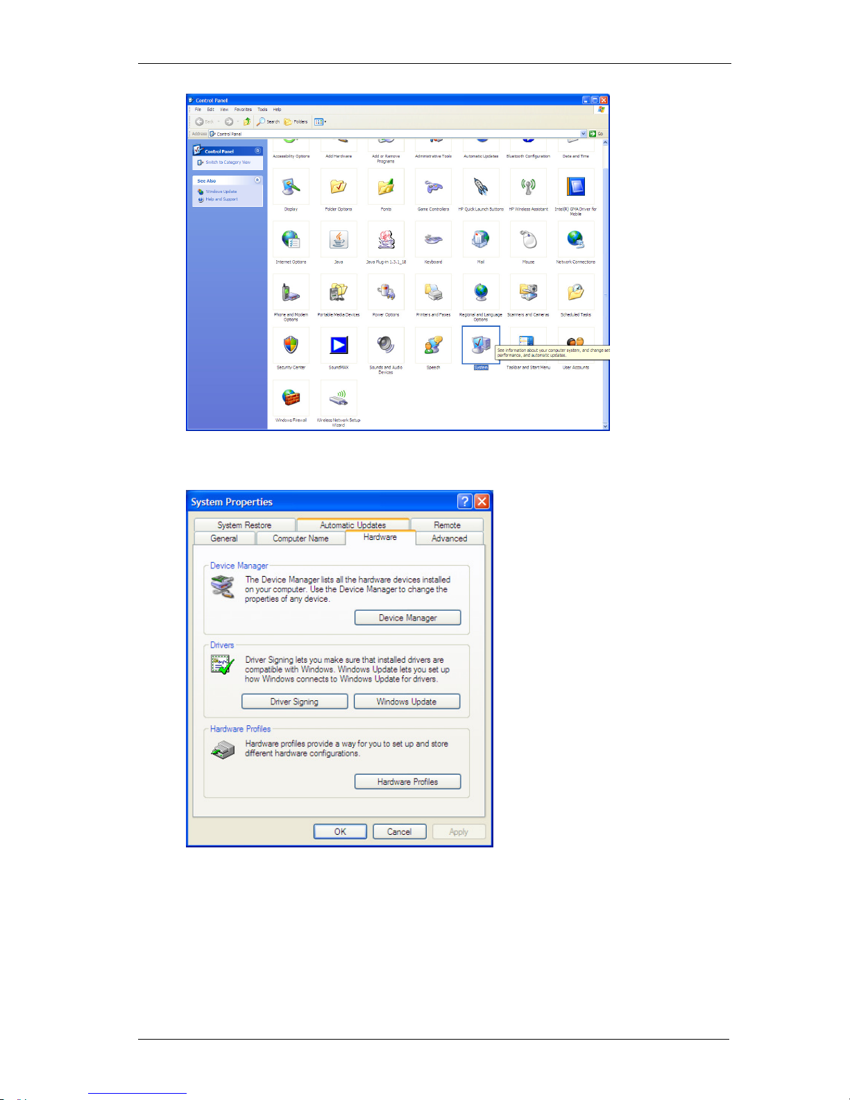
Open the “control panel”
Select “System”
Page 38
DATAMARS
R-IN 1300 MC User Manual – Rev 6.0
37 (50)
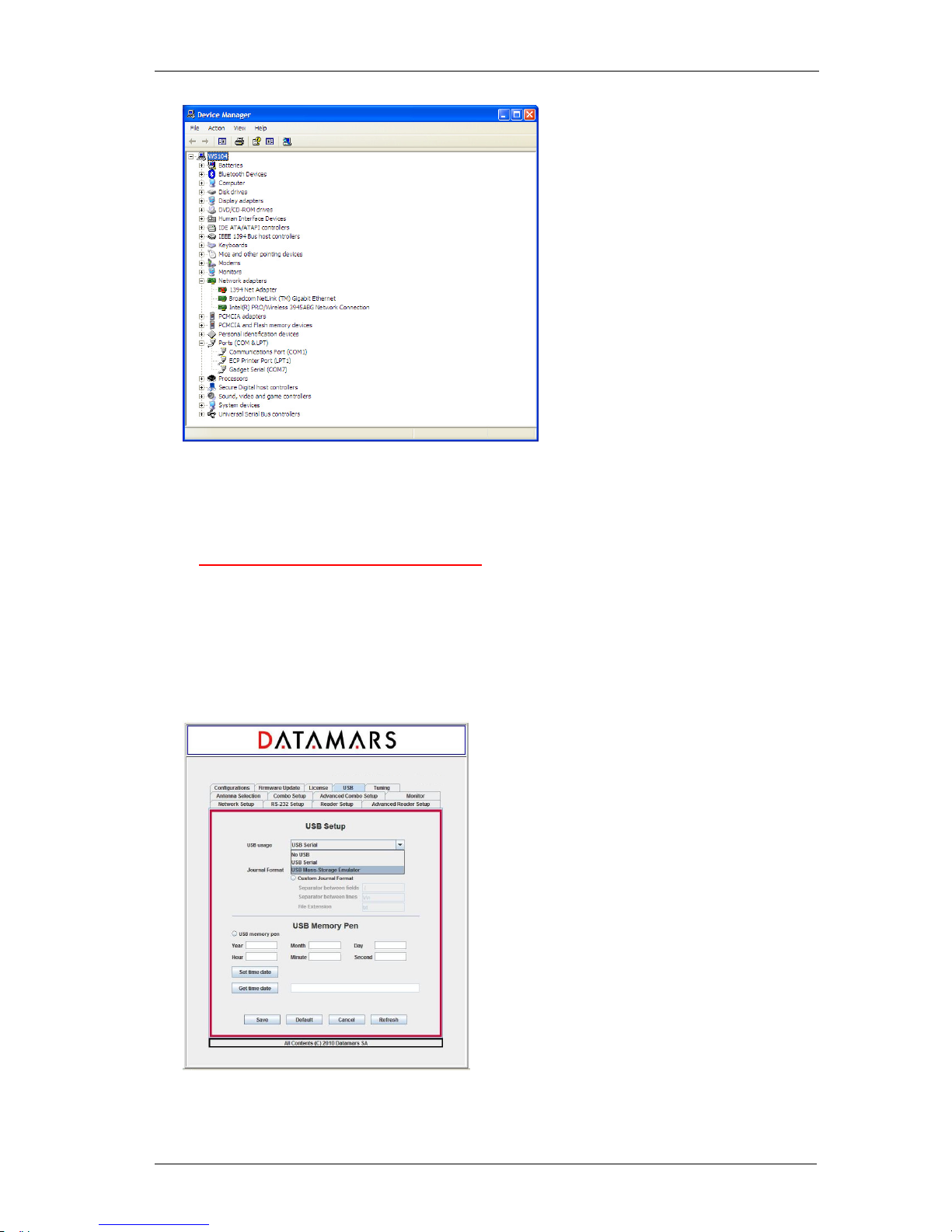
Select “Hardware” and “Device Manager”:
Select “Ports” to see which COM corresponds to the “USB-Gadget Serial”(ie: COM7).
Now you can open a terminal on “Gadget Serial” (ie: COM 7) without need to specify baudrate,
data-bits, parity-bit, stop-bit and flow-control.
Page 39
DATAMARS
R-IN 1300 MC User Manual – Rev 6.0
38 (50)
Note: If the USB-Cable is unplugged, the USB-Serial-Communication stops. If now you plug the
USB-Cable in, the USB-Serial-Communication will NOT start! After unplugging, you have to close
the terminal, plug the USB-Cable again and open a new terminal.
6.2 USB MASS STORAGE EMULATION
To use the mass storage emulation please follow carefully the following instructions.
At the beginning of the manipulation, the reader is assumed to be turned off.
• Make sure that your PC and the “R-IN1300 MC Advanced” are NOT connected via USB-cable
• Turn the reader on
• If not yet selected, activate the “USB Mass Storage Emulator” functionality with *us2” (on
terminal) or via GUI
• Start reading: the detected UIDs are written into the journal-file (duplicated UIDs are filtered –
each UID is written only once)
ARM: 4.0.0 / DSP 2.1.4 Type: MC
Page 40
DATAMARS
R-IN 1300 MC User Manual – Rev 6.0
39 (50)
• Stop reading
• Plug in the USB-cable and connect your PC with the “R-IN1300 MC Advanced” (USB-cable
AB)
• For technical reason wait 4-5 seconds so that the system can prepare the journal-file.
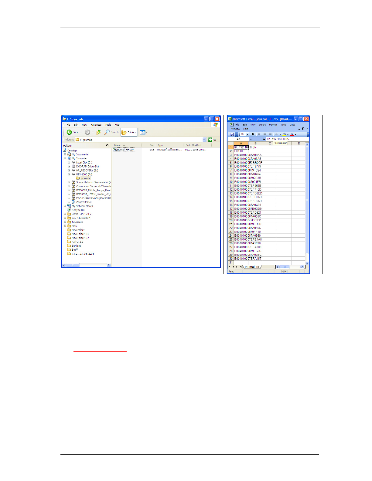
• Find the journal-file: use Explorer (ie: Drive “F:\R-IN1300\journals\journal_HF.cvs”
Now copy the journal-file on your LocalDisk and open the copy.
Note: If you do not find the journal-file, unplug the USB-Cable and plug it in again until the system
detects the presence of the file.
• Unplug the USB-Cable and turn the reader off
• Repeat the whole procedure from the beginning
Please note:
The USB-Cable can be plugged in ONLY after the reader has been stopped.
The journal file in the emulated USB-Mass-Storage should not be opened, edited or deleted.
The reader must be reset each time at the end of the procedure.
7 MEMORY PEN
The reader offers the possibility to use a memory-pen to store UIDs into a file called “inventory.txt”.
If this service is enabled, the UIDs detected during the reading-phase are both sent to the selected
output devices (RS232 and/or Ethernet) and written into the memory-pen together with the detectiontimestamp (mandatory) and the antenna-index (optional).
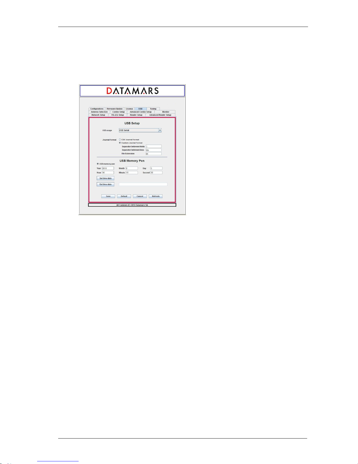
To activate this service, either “USB momory pen” field on the GUI had to be selected or “*mp1” in the
RS232-terminal has to be typed.
To disable it, either the “USB momory pen” field on the GUI has to be cleared or “*mp0” in the RS232terminal has to be typed.
Page 41
DATAMARS
R-IN 1300 MC User Manual – Rev 6.0
40 (50)
The current date and time on the reader can be set and retrieved using the GUI or with the RS232terminal typing respectively the command “*td[-DD-MM-YYYY-hh-mm-ss]” (set --- ex *td-31-08-201017-15-30) and “*td” (get).
Note: the system time and date must be set after each reboot of the reader.
After having enabled the memory-pen usage, the insertion of a memory-pen into the reader is
mandatory.
Failing in doing so, the error led turns to red.
If the memory-pen is inserted, the error led remains green indicating that it is safe to start reading.
During the reading- and detection phase the error led blinks red indicating that it is not advisable to
remove the memory-pen because of possible loss of data.
At the end of the reading and detection phase the error led stops blinking red signalling which it is
safe to remove the memory-pen.
After removing the memory-pen, another one must be inserted into the reader to start another
reading-phase.
ARM: 4.0.0 / DSP 2.1.4 Type: MC
Page 42
DATAMARS
R-IN 1300 MC User Manual – Rev 6.0
41 (50)
8 TUNING
The noise-meter function only works in TableTop-Mode with ISO-15693 technology.
It is therefore possible that your current configuration needs to be modified. It is recommended to
save your current configuration into a file on your PC, to restore the default configuration on the
reader, perform the needed measurements and in case reload your specific configuration.
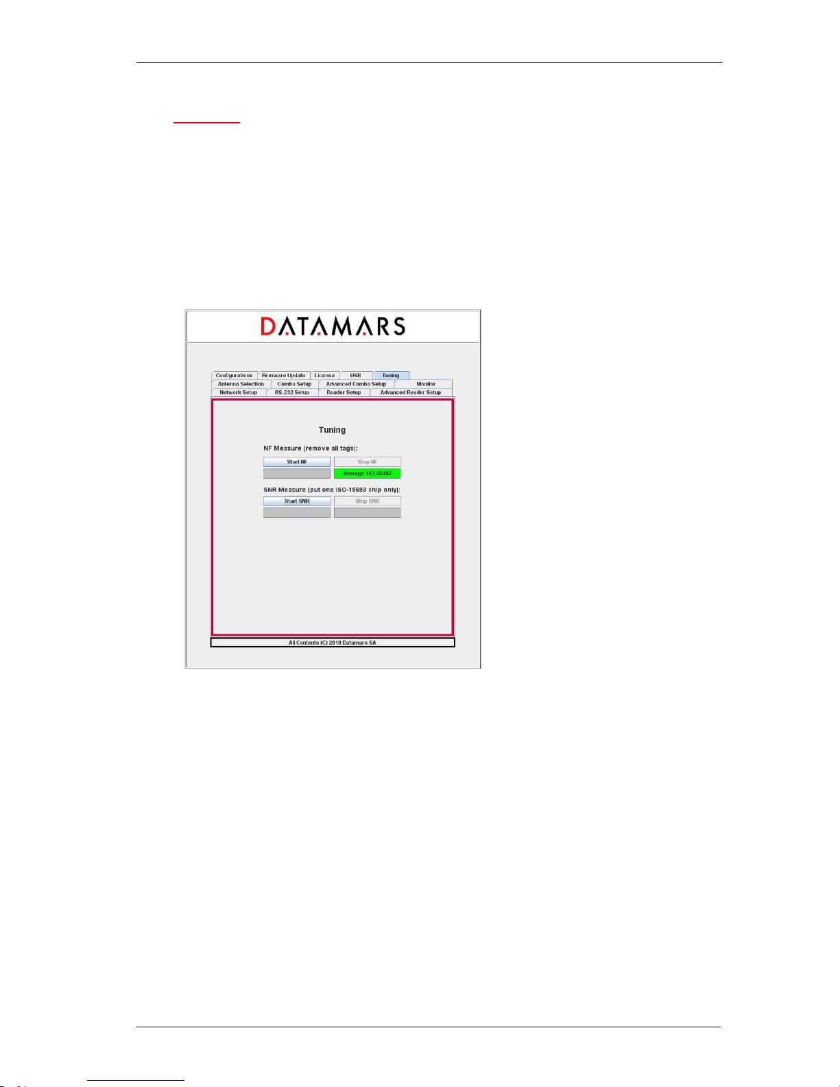
To start the noise floor (NF) estimation press the Start NF button. The value in the gray box starts to
be updated in real time and the coloured box changes its colour in real time (green, yellow or red)
according to the estimated noise. Please note that during this phase no tag must be in the magnetic
field of the antenna.
To stop the NF measurement, press the STOP NF button. The average value is computed and
depicted in the coloured box.
Once the noise floor is available, it is possible to compute the signal to noise ratio (SNR).
To start the SNR measure, press the Start SNR button and place only one ISO-15693 tag in the
magnetic field of the antenna. In the gray box appears the estimated real time value. To stop, press
the Stop SNR button.
ARM: 4.0.0 / DSP 2.1.4 Type: MC
Page 43
DATAMARS
R-IN 1300 MC User Manual – Rev 6.0
42 (50)
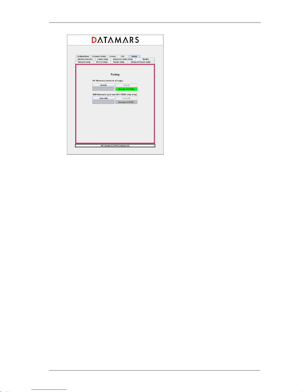
The average value is computed and shown in the box below the Stop SNR button.
ARM: 4.0.0 / DSP 2.1.4 Type: MC
Page 44

DATAMARS
R-IN 1300 MC User Manual – Rev 6.0
43 (50)
9 TECHNICAL SPECIFICATIONS FOR R-IN1300 MC
9.1 OPERATIONAL CHARACTERISTICS
The DATAMARS RFID reader “R-IN1300 MC” is an integrated analog system for RFID- Applications
(RFID=radio frequency identification) which works at 13.56MHz. It allows reading data stored into
ISO-RFID transponders or ISO-Labels at 13.56 MHz. Single- and Multi-read operation are supported.
The communication between the reader and the transponder is based on the ISO 15693 (Part 1-3)
protocol.
All transponders (contact less memories) are powered by a transmitted carrier radio wave at
13.56MHz and are compliant with the ISO 14443-B recommendation for the transfer of power and
signals via radio transmission. For this purpose the reader “R-IN1300 MC” amplitude, modulates the
data on the carrier using amplitude shift keying (ASK) and the tag replies by load modulating the data
on the carrier.
Once the reader is connected to an appropriate client-network (via dedicated computer) it works
based on the installed software like a server providing the received data from the transponders to the
final client-application.
The service software helps to control and update the reader in user-friendly way.
“R-IN1300 MC” supports different antennas as well as multiple configurations.
9.2 ELECTRICAL CHARACTERISTICS
The technical specifications include only the High Frequency “R-IN1300 MC” and not the Low
Frequency reader R-IN7500.
Electrical characteristics (without antenna)
POWER SUPPLY
AC 100-240V 1A 50-60 Hz
POWER CONSUMPTION
35 W
ANTENNA OUTPUT POWER
12 W
Technical characteristics
OPERATING FREQUENCY
13.56 MHz
OPERATING TEMPERATURE
0°C - 50°C / 32°F - 122°F
DIMENSIONS
220 x 135 x 245 (mm) / 8.66 x 5.31 x 9.65 (inches)
WEIGHT
4.0 kg
TRANSPONDER TYPE
ISO15693 (T-BT 1320, T-BT1315, T-BT1313, T-BT1311)
I-Code 1
ANTI COLLISION
Yes
COMMUNICATION PROTOCOL
RS-232, USB, TCP/IP (Ethernet)
Page 45
DATAMARS
R-IN 1300 MC User Manual – Rev 6.0
44 (50)
AUTO TUNING
No
ANTENNA TYPES
Table Top, Tunnel, Bin, Chute, others on request
READING SPEED
Depend on number of transponder and technology (up to
40/s)
READ/WRITE
Read / Write
EMC
High attenuation characteristics (~30÷60 dB)
IP PROTECTION DEGREE
IP51. Upon request: improved with gasket to IP54 (splashresistant and dust-protected)
MAX. READABLE TRANSPONDERS
1000 pieces
Hot
With high power transmission the housing might become hot!
9.3 REGULATIONS
9.3.1 EQUIPMENT MODIFICATION
Equipment modifications not expressly approved by Datamars SA, CH-6930 Bedano, the party
responsible for FCC compliance, are forbidden. Such modifications could void the user’s warranty and
authority to operate the equipment and cause hazardous conditions.
9.3.2 EN 300330-1/-2 (EUROPE)
The “R-IN1300 MC” system is a sending and receiving equipment and is in accordance with the R &
TTE directive
EN 300 330-1/-2. The “R-IN1300 MC” system fulfils the requirements of this regulation.
9.3.3 FCC (USA)
To comply with FCC part 15 rules in the United States, the system must be professionally installed to
ensure compliance with the Part 15 certification. It is the responsibility of the operator and
professional installer to ensure that only certified systems are deployed in the United States. The use
of the system in any other combination (such as co-located antennas transmitting the same
information) is expressly forbidden.
9.3.4 IC (CANADA)
The device has been designed to operate with the antennas listed below, and having a maximum gain
of 2 dB. Antennas not included in this list or having a gain greater than 2 dB are strictly prohibited for
use with this device. The required antenna impedance is 50 ohms.
List of antennas: Datamars antenna A-ST1330 TT
Please ask for more antennas which are not listed above.
In order to reduce potential radio interferences to other users, select the antenna type and gain as
follows:
equivalent isotropically radiated power (e.i.r.p.) not higher than the permitted one for a successful
communication.
Page 46

DATAMARS
R-IN 1300 MC User Manual – Rev 6.0
45 (50)
Operation is subject to the following two conditions:
(1) this device may not cause interference, and
(2) this device must accept any interference, including interference that may cause undesired
operation of the device.
9.3.5 CE CERTIFICATION
The system “R-IN1300 MC” is in accordance with the requirements of protection, which are defined in
the regulation concerning the electromagnetic tolerability EN301 489-1, -3, emitted by the council for
the harmonisation of regulations in the member countries. The European Community regulation for
Low Frequency, EN 60950, is respected. The “R-IN1300 MC” system fulfils the requirements of this
regulation.
9.3.6 WARRANTY
If the reader is opened by not certified personnel the warranty automatically expires and Datamars
cannot guarantee the fulfilments of the above-mentioned regulations.
Page 47
DATAMARS
R-IN 1300 MC User Manual – Rev 6.0
46 (50)
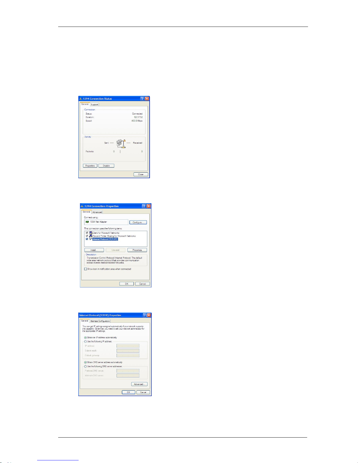
APPENDIX A – CONNECTING THE R-IN1300 MC TO A PC WITH A CROSS CABLE
If the reader “R-IN1300 MC” is directly connected to a PC, you must still do following steps:
Open the “Network Connections” frame of Windows (Hint: Start -> Settings -> Network
Connections) and double-click the entry corresponding to the connection you intend to use to
communicate with the reader. You will see a similar frame:
Click the button “Properties” of the tab “General” to get access to the “Connection Properties”
frame. You will see a similar frame:
Highlight the “Internet Protocol (TCP/IP)“ and click the “Properties” button to get access to the
“Internet Protocol (TCP/IP) Properties” frame. You will see a similar Frame:
Note exactly the current configuration of the tab “General” in order to be able to restore it.
Page 48
DATAMARS
R-IN 1300 MC User Manual – Rev 6.0
47 (50)
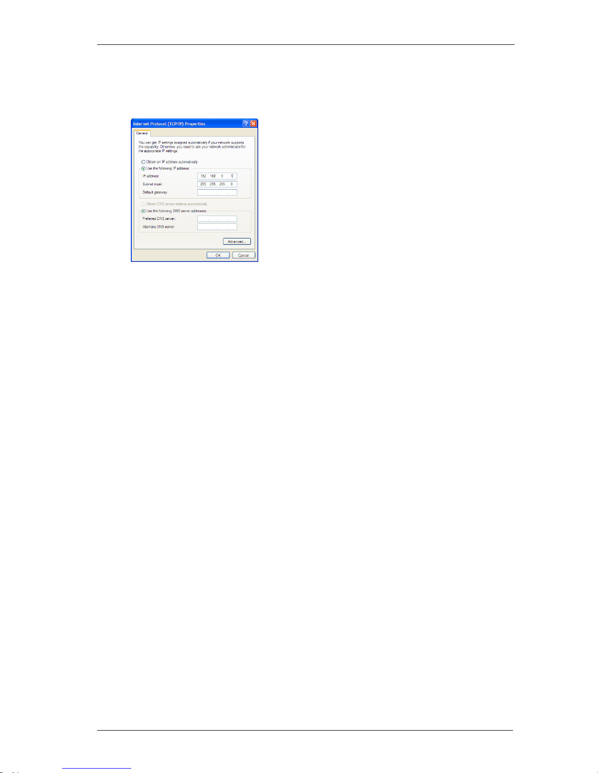
Click the “Use the following IP address” radio-button and specify an IP in the same range of the
readers IP (i.e. 192.168.0.1), the subnet-mask (255.255.255.0). You can ignore the “Default
Gateway”.
Leave the configuration tool confirming by clicking the OK button.
Page 49
DATAMARS
R-IN 1300 MC User Manual – Rev 6.0
48 (50)
APPENDIX B - CODE LENGTH
In terminal mode you can configure the reader to return the UID code in 4 different formats:
1. *cl0:
Standard 16 characters UID
2. *cl1 to *cl9:
The reader returns only the right most digits of the original 16 digit UID.
With this format it is not possible to guarantee the uniqueness of the codes !
3. *cl5:
The reader returns 12 digits code in the fashion of “cl2”, but in this case the first (left) chapter
ranges from “G” to “Z” instead of from “0” to “F”.
With this format it is not possible to guarantee the uniqueness of the codes !
Page 50
DATAMARS
R-IN 1300 MC User Manual – Rev 6.0
49 (50)
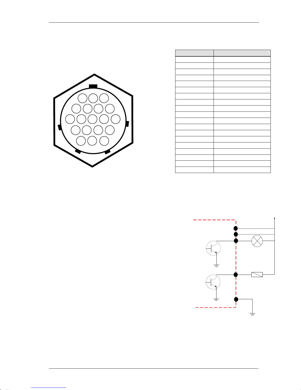
APPENDIX C - I/O PIN CONFIGURATION
BINARY INPUTS:
There are 3 binary inputs 5-48 VDC available for customer specific needs: A, B, S, T and U&V.
The inputs are isolated through galvanic opto-couplers.
BINARY OUTPUTS:
Digital Outputs:
There are 7 digital npn-Open-Collector outputs available: G,
H, J, K, N, P, and R.
The 'open collector' output is the unconnected Collector of an
NPN transistor, made available to the external circuitry that
switches to ground when active. This type of output can be
used with a pull-up resistor to translate a logic level from one
voltage to another or to drive bulbs, relays etc, that have a
positive voltage on one terminal and require a switch to
ground for activation.
All of them are software configurable. Connect the POWER
OUT and the Digital out as shown in the picture. The 24V can
be supplied by the internal power source (pin C, max 500mA)
or an external power source. In this case connect the pin D to
ground.
Note: when using output A1, A2, A3 protect the I/O connecting
the POWER OUT B (I/O PIN F) to the VDC. When using
output A4, B1, B2, B3 protect the I/O connecting the POWER
OUT A (I/O PIN E) to the VDC.
Relays:
There is a dry contact (L and M) to switch higher loads which can be controlled via software.
Max. Voltage switch 50V (DC/AC)
Max. Current switch 3A
Max. Power switch 60W, 120 VA
A B
D C E F G H J K L
M
T U N V P R S
I/O PIN FUNCTION
A IN+1
B IN-1
C 24V
D GND 24V
E POWER OUT A
F POWER OUT B
G Digital Out A4
H Digital Out A1
J Digital Out A2
K Digital Out A3
L K500 Common
M K500 Open
N Digital Out B1
P Digital Out B2
R Digital Out B3
S IN+2
T IN-2
U IN+3
V IN-3
R - IN 1300
Output I / O Conn
ector
R - IN 1300 : Digital Output
H
E
E
POWER OUT A
Digital out A 1
Lamp
K
Digital out A 3
24
V external power
supply or pin C
Relay
D E F
POWER OUT B
Page 51

DATAMARS
R-IN 1300 MC User Manual – Rev 6.0
50 (50)
APPENDIX D - TROUBLESHOOTING
If you run into any problem using your reader, use the following table to troubleshoot the problem. If
the problem persists, contact support at [email protected] or +41 91 935 73 80.
SYMPTOM CAUSE AND/OR CORRECTIVE ACTIONS
There are transponders on the antenna but the
software displays no UID.
• Is the antenna cable connected to the
reader?
• Is the antenna connected to the connector
named “1”?
• Are the transponders you want to read
specified in the options?
• Is the HF led on?
If the four previous points didn’t solve the
problem turn the reader off, wait 10 seconds
before turning the reader on again
The red light “Antenna” is on.
• Is the antenna connected to the right
connector?
Verify the selected channel.
• Is the antenna placed near metallic objects?
Move the antenna. Keep 1.5m distance from
any metallic objects.
Bad reading or low reading distance
• The antenna is near metallic objects or noise
source like electric motors?
Try to move the antenna and the reader away
from these objects.
The reader reads transponder (Tag LED lights
on) but the software displays no UID
• Is the RS-232 cable well connected ti the
Host Interface?
• Is the software set 115200 bps – 8 – N – 1 –
N?
Verify the connection
 Loading...