

R-IN1300
2006
R-IN1300 MC
R-
IN1300 SC
preliminary VERSION
INSTALLATION &
OPERATION MANUAL
TABLE OF CONTENTS
RFID - Technology
Installation & Operation Manual V 1.4
2 (19)
V1.0/December

Table of contents..........................................................................................................................................2
1 Introduction............................................................................................................................................4
2 Hardware connections.........................................................................................................................6
2.1 Mounting........................................................................................................................................7
3 Operation with terminal.......................................................................................................................8
3.1 List of the commands of the reader...........................................................................................8
4 Technical specifications for R-IN1300 ............................................................................................13
4.1 Operational characteristics.......................................................................................................13
4.2 Electrical characteristics............................................................................................................13
5 Regulations.........................................................................................................................................15
5.1 Equipment Modification.............................................................................................................15
5.2 EN 300330-1/-2 (europe)..........................................................................................................15
5.3 FCC (usa)....................................................................................................................................15
5.4 IC (canada)..................................................................................................................................15
5.5 CE certification............................................................................................................................15
5.6 Warranty......................................................................................................................................16
6 Troubleshooting..................................................................................................................................17
appendix a - code length .........................................................................................................................18
appendix b - I/O Pin Configuration........................................................................................................19
Installation & Operation Manual V 1.0 3 (19)
1 INTRODUCTION
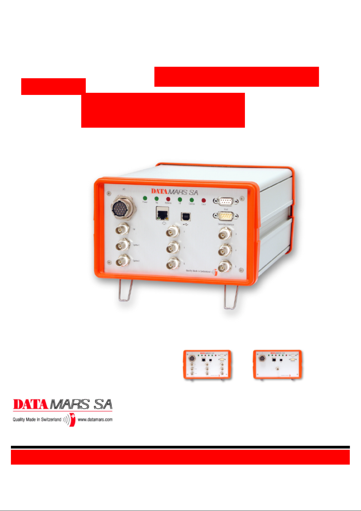
The Datamars R-IN1300 High Frequency (HF) RFID-reader, designed to work in industrial
environment, is resistant to vibrations, electromagnetic interferences and is able to detect the
following transponder technologies:
§ T-BT 1320 & T-BT1315 (ISO 15693), HF
§ T-BT 7xxx serie, LF (only with Datamars R-IN7500 reader connected externally)
§ Other types of transponders could be read in “Combo” mode.
The reader is able to find simultaneously more than one High Frequency (HF - multi read)
transponder1 and one Low Frequency (LF – single read) chip at the same time if you have a RIN7500 Low Frequency reader connected on the Secondary Interface.
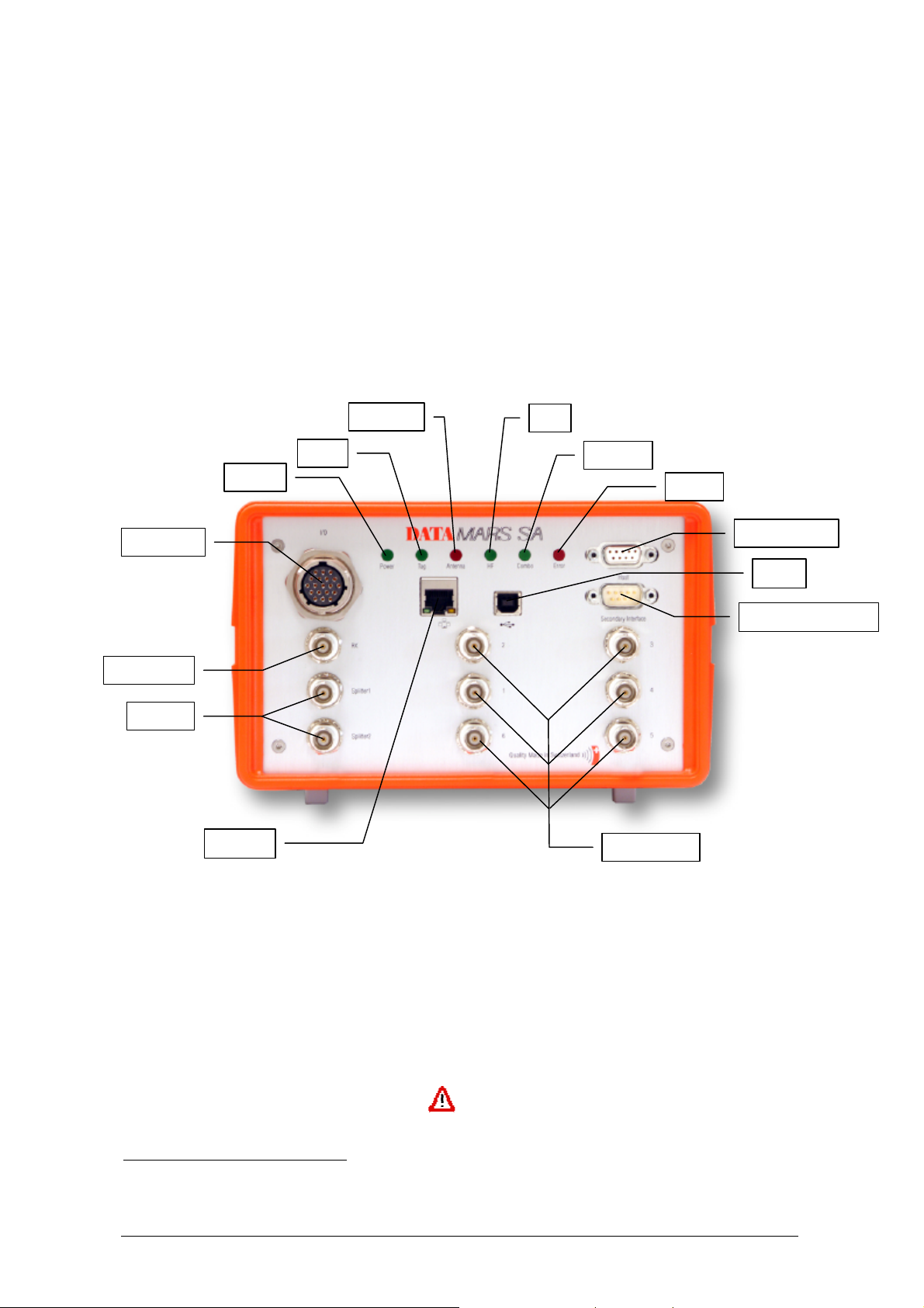
Antenna
HF
Tag
Power
Digital I/O
RX Antenna
Splitter
Ethernet
Combo
Error
Host Interface
USB
Secondary Interface
HF Antennas
LEDs
Power lights on when the reader is switched on
Tag lights on when one or more transponder are detected
Antenna lights on when the antenna is not tuned or is near metallic objects or
not connected
HF High Frequency reading is ON
Combo The system is working in Combo mode (see chapter 2)
Error General Error
Antennas
HF Antennas TX/RX antenna channels from 1 to 6
Splitter 2 splitted channels (0° phase shift)
RX Antenna RX channel very sensibile!
1
the quantity of transponders detected and the accuracy of it can change depending on the used transponder, the environment,
the size of the antenna, etc.
Installation & Operation Manual V 1.0 4 (19)
Interfaces
Digital I/O Digital Inputs and Outputs (see appendix B).
Host Connect to any serial port (COM) on your PC with RS-232 cable or to
any other RS232 Terminal.
Secondary Interface Used in Combo mode (see chapter 2).
USB N/A
Ethernet (Web Server) connect to LAN with a standard Ethernet cable.
For more info in Ethernet communication please request the “R-
IN1300 communication manual” to support@datamars.com
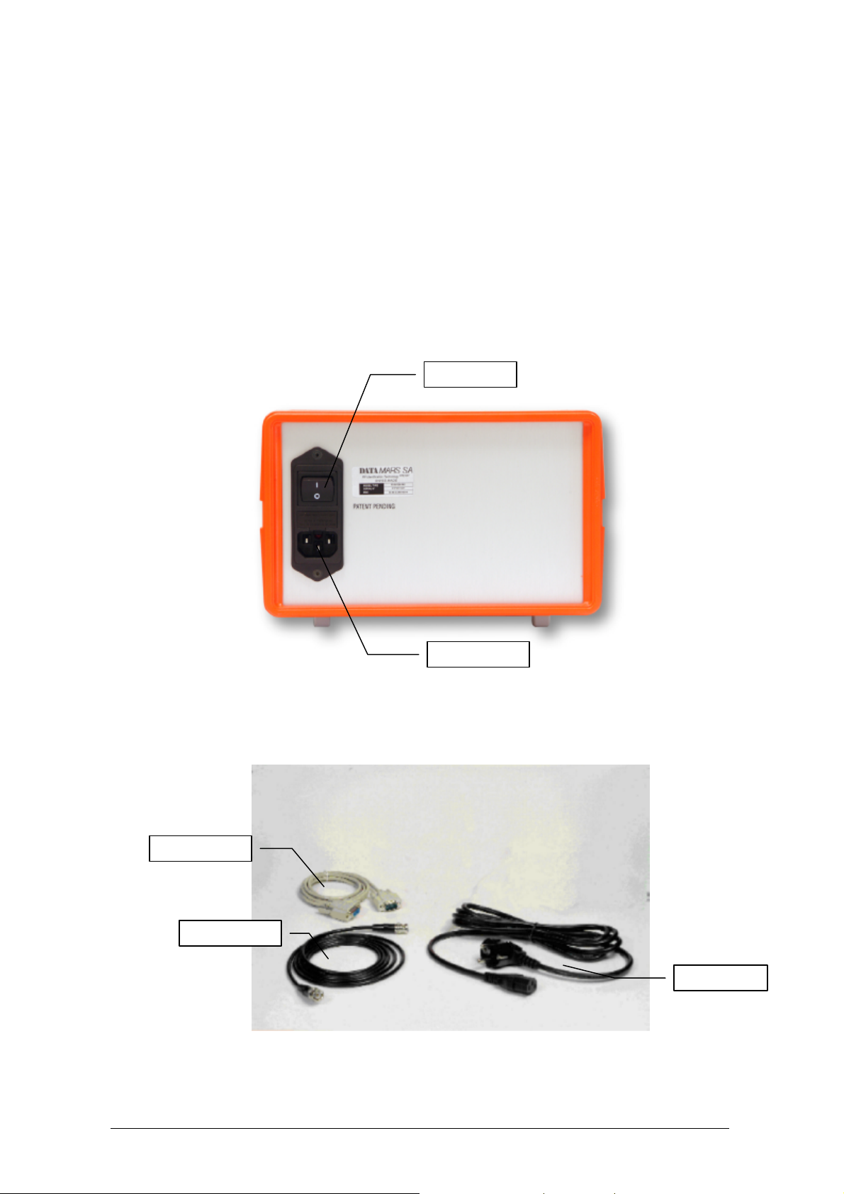
Power Switch Turn ON and OFF the reader.
Power Supply connect the power supply cable (100-240VAC, 50-60 Hz).
Power Switch
Power Supply
RS-232 Cable
Coxial Cable
Power Cable
Installation & Operation Manual V 1.0 5 (19)
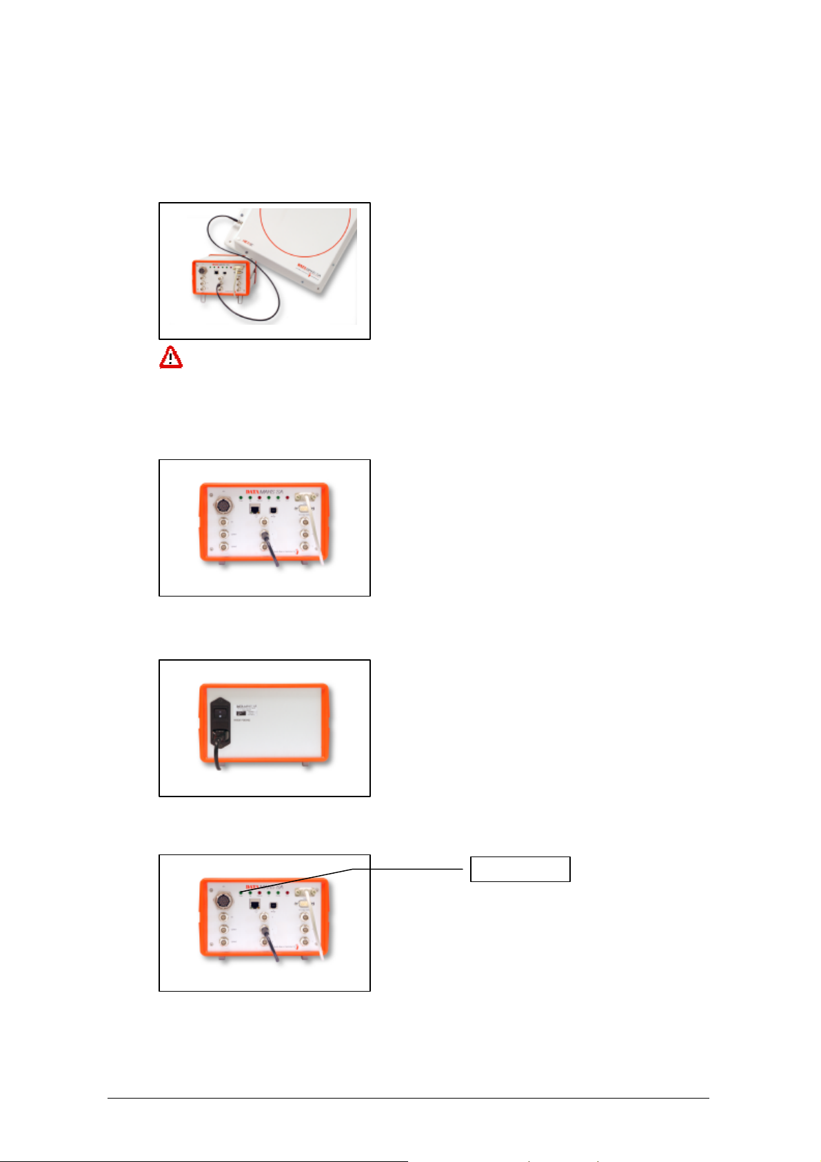
2 HARDWARE CONNECTIONS
1. Antenna:
Connect the black coaxial cable from the antenna to the connector marked as “1”
You can not use cable other than the 3.66m coaxial 50? cable supplied by
Datamars SA. Additional cables at disposal.
2. PC/Terminal
Connect the serial white cable from the connector marked “Host” to any serial port (COM) on
your PC
3. Power
Connect the power cable 110 – 240 V AC and be sure that it is well fixed.
4. Set the Power Switch to ON and check if the green LED (Power) is on.
5. Wait until lights “Tag” and “Antenna” stop flashing (~20 seconds).
Green light on
Installation & Operation Manual V 1.0 6 (19)

IMPORTANT:
Please place the antenna as far as possible from metallic surfaces to avoid possible reading
interferences and avoid to mount it in places where a regular ventilation is not granted.
If the light “Antenna” turns on, the antenna might be too close to metallic surfaces or not
tuned.
After the reader is turned on for some time the temperature might increase.
Do not plug/unplug any connectors while the reader is turned ON.
In case you have an R-IN7500 LF reader installed you can keep the same configuration. You just
need to unplug the serial cable from the PC and connect it to the R-IN1300 reader to the connector
marked as “Secondary Interface”.
If you have a new R-IN7500 NMS:
1. Connect the Low Frequency (LF) Antenna to the connector marked “Ant.0” on the reader
2. Connect a serial cable the connector “RS-232” mentioned on the R-IN7500 to the connector
“Secondary Interface” mentioned on the R-IN1300 reader.
3. Connect the power cable
4. Turn the reader on
Keep a distance between the LF and the HF antenna (min. 1m) in order to not influence the
reading distance or use a combo antenna (A-ST1330 CBO) to read LF and HF transponders at
the same time with the same antenna.
2.1 MOUNTING
The reader can be simply laid down on the table or be mounted on the wall or under a table using the
appropriate wall mounting system.
Installation & Operation Manual V 1.0 7 (19)

3 OPERATION WITH TERMINAL
For operation with terminal use any kind of terminal for example Windows HyperTerminal with the
following settings:
• Bits per second 115200
• Data bits 8
• Parity None
• Stop bits 1
• Flow control None
3.1 LIST OF THE COMMANDS OF THE READER
All commands must be followed by a carriage return (ENTER)
General Commands
*d Detect:
*t Totalize:
*i Interrupts any continuous mode operation (does not disable the
*x List of the commands and settings
*se Settings:
*st Store UIDs (Any stored UIDs will disappear after power off)
*dw Download all the codes previously stored with *st
Explanation
returns the UID-list of all the HF transponders in the field
Returns the number of HF transponders present in the field
continuous mode)
Displays the current settings (Notice that the settings are maintained
after power off)
Installation & Operation Manual V 1.0 8 (19)

General settings
Details for *it1:
Explanation
*ec[_] Echo:
*ec0 echo disabled (default)
*ec1 echo enabled
“echo” makes it possible to view the characters sent to the reader.
*co[_] Continuous mode:
*co0 continuous mode enabled (default)
*co1 continuous mode disabled
*rh[_] Remove headers:
*rh0 does not remove the headers
*rh1 removes the headers (default)
*it[_] Input trigger:
*it0 input trigger disabled (default)
*it1 input trigger 1 enabled
*it2 input trigger 2 enabled
Input 1
(IN±1)
t
1
Use:
• When IN1 is high level, it’s possible to read the transponder.
• t1 min 10 ms.
• See Appendix B to know where IN±1 pins are.
• See Appendix B for electric characteristics of the input.
Details for *it2:
Input 1
(IN±1)
t
1
Input 2
(IN±2)
t
1
t
2
Installation & Operation Manual V 1.0 9 (19)

Use:
• The rising edge of IN1 starts reading
• The rising edge of IN2 stops reading
• t1 min 100 us
• t2 min 100 ms
• See Appendix B to know where IN±1 pins are.
• See Appendix B for electric characteristics of the input.
*bu Not available
*rd Restore default settings
*kw Not available
*rm[_] Reader request rate:
*rm0 Reader mode SLOW* (1 out of 256)
*rm1 Reader mode FAST (default) (1out of4)
*mt[_] Modulation type:
*mt0 modulation type ASK*
*mt1 modulation type FSK (default)
*tm[_] Tag response rate:
*tm0 tag mode SLOW*
*tm1 tag mode FAST (default)
*mi[_] Modulation index:
*mi0 modulation index 10%
*mi1 modulation index 30% (default)
*mi2 modulation index 100%
*sa[_] Stand alone mode:
*sa0 stand alone mode disabled (default)
*sa1 stand alone mode enabled (detect)
*sa2 stand alone mode enabled (totalize)
When stand alone mode is enabled the device will start reading as
soon as it turned on.
*br[_] baud rate:
*br0 baud rate 9600
*br1 baud rate 19200
*br2 baud rate 38400
*br3 baud rate 57600
*br4 baud rate 115200 (default)
*tt[_] Tag technology:
*tt1 tag technology ISO 15693(T-BT1320 T-BT1315) (default)
*tt2 tag technology Philips I-Code I (not available).
*tt4 tag technology TI Tag It (not available).
*ts[_] Time slots:
*ts0 time slots single
*ts1 16 times slots (default)
*xm[_] Rx mode:
*xm0 mode Rx/Tx (one antenna connected to channels 1 to 6) (default)
*xm1 mode Rx and Tx separate (two antennas : one connected to
channels 1 to 6 and the other connected to RX channel).
*cl[_] Code length:
See Appendix A for more details.
*cl0 16 characters UIDs (standard, default)
*cl1 10 characters UIDs (base conversion) not implemented
*cl2 12 characters UIDs (partial code)
*cl3 12 characters UIDs (First character special)
*an[_] HF antenna select:
Selects the channel to which the antenna is connected (if the reader is
Multichannel).
*an0 select HF antenna 1 (default)
*an1 select HF antenna 2
Installation & Operation Manual V 1.0 10 (19)

*an2 select HF antenna 3
*an3 select HF antenna 4
*an4 select HF antenna 5
*an5 select HF antenna 6
*an6 splitter (two antennas connected to splitter 1 and 2).
*at[_] Antenna type selection:
*at0 table top antenna. (default)
*at1 tunnel antenna (no elimination of double codes) not implemented
*at2 tunnel antenna(with elimination of double code) not implemented
*at3 bin antenna(no elimination of double code) not implemented
*at4 bin antenna(with elimination of double code) not implemented
*pw[_] Output power:
*pw[0 .. 12000] range of power from 0 to 12000 mW (default 4000 mW)
- Example *pw4000
The selected output power is not exactly the transmitted power.
The output power value is an approximate value.
*nl[_] New Line character(s) selection:
*nl0 line feed and carriage return(0x0D 0x0A) (default)
*nl1 line feed(0x0A)
*nl2 carriage return (0x0D)
*nl3 carriage return and line feed(0x0A 0x0D)
*qm[_] Quiet mode:
When this mode is enabled the transponder will answer just once while
in the antenna field.
*qm0 quiet mode off (default)
*qm1 quiet mode on
*qs[_] Quiet storage:
The transponder will answer only once. To read the transponder again
it has to stay out of the antenna field for at least 2 minutes.
*qs0 quiet storage off (default)
*qs1 quiet storage on (available only with the new T-BT<newname>
*dt[_] Time between UIDs:
This parameter inserts a time delay between the transmission of
codes.
*dt[0..200] range of time between UIDs from 0 to 200 *10ms (default 0
ms)
*lc[_] Lock code:
*lc0 lock code disabled (default)
*lc1 lock code 1 enabled
*lc2 lock code 2 enabled
Details for *lc1:
Any transponder is read just once.
To read a transponder again, another one must be read first.
Details for *lc2 :
Installation & Operation Manual V 1.0 11 (19)

transponder
t
t
Time of transponder out of the field
0
t
1
The transponder is first visible when entering the magnetic field the first time and it is detected only
once without regards to the time spent in the field.
A chip having left the magnetic field can be read again only having spent an amount of time T outside
of it. If the time spent outside the magnetic field is less than T, the chip cannot be detected. The time
T can be configured with the command *ti[].
*ti[_] Time out:
*ti[0 .. 180] time parameter for lock code 2 from 0 [s] to 180 [s] (default
10 [s], example *ti10)
*sk[_] Skip time slot on no response:
*sk0 skip on no response off
*sk1 skip on no response on (default)
*ct[_] Collision threshold parameter:
*ct[0 .. 100] parameter from 0 to 100 (default 33, example *ct33)
*cs[_] Channel Selection:
*cs0 channel I (default). Cable length must be 3,66m.
*cs1 channel I and Q. There are no limitations on the cable length.
*et [_] Communication selection :
*et0 ethernet
*et1 RS232
*et2 RS232 and ethernet (default)
* see ISO 15693 for more details
Installation & Operation Manual V 1.0 12 (19)

4 TECHNICAL SPECIFICATIONS FOR R-IN1300
4.1 OPERATIONAL CHARACTERISTICS
The DATAMARS SA RFID reader R-IN1300 is an integrated analog system for RFID- Applications
(RFID=radio frequency identification) which works at 13.56MHz. It allows to read data stored into ISORFID transponders or ISO-Labels at 13.56 MHz. Single- and Multiread operation are supported. The
communication between the reader and the transponder is based on the ISO 15693 (Part 1-3).
All transponders (contact less memories) are powered by a transmitted carrier radio wave at
13.56MHz and are compliant with the ISO 14443-B recommendation for the transfer of power and
signals via radio transmission. For this purpose the reader R-IN1300 amplitude modulates the data on
the carrier using amplitude shift keying (ASK) and the tag replies by load modulating the data on the
carrier.
Once the reader is connected to an appropriate client-network (via dedicated computer) it works
based on the installed software like a server providing the received data from the transponders to the
final client-application.
The service software helps to control and update the reader in a simple and user friendly way.
R-IN1300 supports different antennas as well as multiple configurations. Please ask for the complete
list of antennas at salesindustry@datamars.com.
4.2 ELECTRICAL CHARACTERISTICS
The technical specifications include only the High Frequency R-IN1300 and not the Low Frequency
reader R-IN7500.
Electrical characteristics (without antenna)
POWER SUPPLY
POWER CONSUMPTION
ANTENNA OUTPUT POWER
Technical characteristics
OPERATING FREQUENCY
OPERATING TEMPERATURE
DIMENSIONS
WEIGHT
TRANSPONDER TYPE
AC 100-240V 1A 50-60 Hz
35 W
12 W
13.56 MHz
0°C - 50°C / 32°F - 122°F
220 x 135 x 245 (mm) / 8.66 x 5.31 x 9.65 (inches)
4.0 kg
ISO15693 (T-BT 1320 or T-BT1315)
ANTI COLLISION
COMMUNICATION PROTOCOL
AUTO TUNING
Installation & Operation Manual V 1.0 13 (19)
Yes
RS-232, USB (upon request), TCP/IP (Ethernet)
No

ANTENNA TYPES
Table Top, Tunnel, Bin,others on request
READING SPEED
READ/WRITE
EMC
IP PROTECTION DEGREE
MAX. READABLE TRANSPONDERS
Dependant on number of transponder and technology (up to
40/s)
Read / Write
High attenuation characteristics (~30÷60 dB)
IP51. Improved with gasket to IP54 (splash-resistant and
dust-protected)
1000 pieces
Hot
With high power transmission the housing might become hot!
Installation & Operation Manual V 1.0 14 (19)

5 REGULATIONS
5.1 EQUIPMENT MODIFICATION
Equipment changes or modifications not expressly approved by Datamars SA, CH-6930 Bedano, the
party responsible for FCC compliance, are forbidden. Such changes could void the user’s authority to
operate the equipment and cause hazardous conditions.
5.2 EN 300330-1/-2 (EUROPE)
The system R-IN1300 is a sending and receiving equipment and is in accordance with the R & TTE
directive EN 300 330-1 / -2.
The system R-IN1300 fulfils the requirements of this regulation.
5.3 FCC (USA)
To comply with FCC part 15 rules in the United States, the system must be professionally installed to
ensure compliance with the Part 15 certification. It is the responsibility of the operator and
professional installer to ensure that only certified systems are deployed in the United States. The use
of the system in any other combination (such as co-located antennas transmitting the same
information) is expressly forbidden.
5.4 IC (CANADA)
The device has been designed to operate with the antennas listed below, and having a maximum gain
of 2 dB. Antennas not included in this list or having a gain greater than 2 dB are strictly prohibited for
use with this device. The required antenna impedance is 50 ohms.
List of antennas: Datamars antenna A-ST1330 TT
Please ask for more antennas which are not listed above.
In order to reduce potential radio interferences to other users, select the antenna type and gain as
follows:
equivalent isotropically radiated power (e.i.r.p.) not higher than the permitted one for a successful
communication.
Operation is subject to the following two conditions:
(1) this device may not cause interference, and
(2) this device must accept any interference, including interference that may cause undesired
operation of the device.
.
5.5 CE CERTIFICATION
The system R-IN1300 is in accordance with the requirements of protection, which are defined in the
regulation concerning the electromagnetic tolerability EN301 489-1, -3, emitted by the council for the
harmonisation of regulations in the member countries. The European Community regulation for Low
Frequency, EN 60950, is respected.
The R-IN1300 system fulfils the requirements of this regulation.
Installation & Operation Manual V 1.0 15 (19)

5.6 WARRANTY
If the reader is opened by not certified offices by mistake we cannot guarantee the fulfillments of the
above mentioned regulations.
Installation & Operation Manual V 1.0 16 (19)

6 TROUBLESHOOTING
If you run into any problem using your reader, use the following table to troubleshoot the problem. If
the problem persists, contact support at support@datamars.com or +41 91 935 73 80.
SYMPTOM CAUSE AND/OR CORRECTIVE ACTIONS
• Is the antenna cable connected to the
reader?
• Is the antenna connected to the connector
named “1”?
There are transponders on the antenna but the
software displays no UID.
The red light “Antenna” is on.
• Are the transponders you want to read
specified in the options?
• Is the HF led on?
è If the four previous points didn’t solve the
problem turn the reader off, wait 10 seconds
before turning the reader on again
• Is the antenna connected to the right
connector?
è Verify the selected channel.
• Is the antenna placed near metallic objects?
è Move the antenna. Keep 1.5m distance from
any metallic objects.
Bad reading or low reading distance
The reader reads transponder (Tag LED lights
on) but the software displays no UID
• The antenna is near metallic objects or noise
source like electric motors?
è Try to move the antenna and the reader away
from these objects.
• Is the RS-232 cable well connected ti the
Host Interface?
• Is the software set 115200 bps – 8 – N – 1 –
N?
è Verify the connection
Installation & Operation Manual V 1.0 17 (19)

APPENDIX A - CODE LENGTH
In terminal mode you can configure the reader to return the UID code in 4 different formats:
1. *cl0:
standard 16 characters UID
2. *cl2:
The reader returns only the right most 12 digits of the original 16 digit UID.
With this format it is not possible to guaranty the uniqueness of the codes !
3. *cl3:
The reader returns 12 digits code in the fashion of “cl2”, but in this case the first (left) chapter
ranges from “G” to “Z” instead of from “0” to “F”.
With this format it is not possible to guaranty the uniqueness of the codes !
Installation & Operation Manual V 1.0 18 (19)

APPENDIX B - I/O PIN CONFIGURATION
A B D C E F G H J K L M T U N V P R S
BINARY INPUTS:
There are 2 binary inputs 5-48 VDC available for customer specific needs. The inputs are isolated
through galvanic opto-couplers.
BINARY OUTPUTS:
Digital Outputs:
There are 7 digital npn-Open-Collector
outputs available: G, H, J, K, N, P, and R.
The 'open collector' output is the
unconnected Collector of an NPN transistor,
made available to the external circuitry that
switches to ground when active. This type
of output can be used with a pull-up resistor
to translate a logic level from one voltage to
another or to drive lamps, relays etc, that
have a positive voltage on one terminal and
require a switch to ground to activate.
All of them are software configurable. The
maximum output current is 500mA. See
picture example.
Relais:
There is a dry free contact (L and M) to
control higher loads which can be controlled
via software.
Max. Voltage switch 50V (DC/AC)
Max. Current switch 3A
Max. Power switch 60W, 120 VA
I/O PIN FUNCTION
A IN+1
B IN-1
C 24V
D GND 24V
E POWER OUT A
F POWER OUT B
G Digital Out A4
H Digital Out A1
J Digital Out A2
K Digital Out A3
L K500 Common
M K500 Open
N Digital Out B1
P Digital Out B2
R Digital Out B3
S IN+2
T IN-2
U 3.3V
V GND
R-IN1300 : Digital Output
POWER OUT A
Digital out A1
Digital out A3
R-IN1300 Output
I/O Connector
E
E
H
K
Lamp
Relay
24V
Installation & Operation Manual V 1.0 19 (19)

Via ai Prati
CH-6930 Bedano - Lugano
Switzerland
Phone +41 91 935 73 80
Fax +41 91 945 03 30
email support@datamars.com
Installation & Operation Manual V 1.0 20 (19)
 Loading...