

Page 1
DATAMAN S4 MANUAL
Introduction to S4
DATAMAN S4 is a battery-powered PROM
programmer for Microsystem Designers. It can
readily be used for production programming
too.
S4 contains 128k, 256k or 512k of RAM which
retains data and configuration even when
switched off. The RAM can be downloaded
with data and manipulated either remotely from
a computer via RS232 interface or directly from
S4's keypad. S4 provides plug-in emulation for
PROMS via a 24/28/32 pin emulator lead. The
development method is that a new program
can be tried out by emulation. When it works, a
PROM can be programmed, plugged into the
system and the jobs done. Programming
facilities include EPROMS of the 27 series,
such as 2716 or 278000, also FLASH
EPROMS and most EEPROMS, including 28,
52, 55 & 98 series.
Introduction to S4 1
Page 2

DATAMAN S4 MANUAL
Other devices can be programmed, such as
single-chip microprocessors, but some require
a plug-in adaptor.
Check List of Parts and Accessories
1. Dataman S4
2. Manual
3. Write Lead 2mm plug to Minihook
4. EMULead - Ribbon cable with 32 pin
DIL plug
5. LIBRARY ROM
6. Disk with Terminal Driver and Utilities
7. Mains charger
Three Year Guarantee
S4 has a back-to-base guarantee to the
original purchaser for three years from date of
purchase. All electronic parts and labor are
covered, except the batteries which are only
covered for the first year. To make a claim, first
telephone us with details of the fault. Some
problems can be fixed quickly without any
need for us to see the product. You can fit new
batteries yourself, for example. If we need to
see it, we will give you a returns number: then
you should send the product back to us directly,
quoting that number. Sending it to a dealer
usually wastes time. We aim to return repairs
in less than two working days. It helps if you
include a written description of the fault. If the
product develops a fault when it is out of
guarantee then there is a fixed repair charge.
At time of writing it is £95 plus carriage.
2 Introduction to S4
Page 3
DATAMAN S4 MANUAL
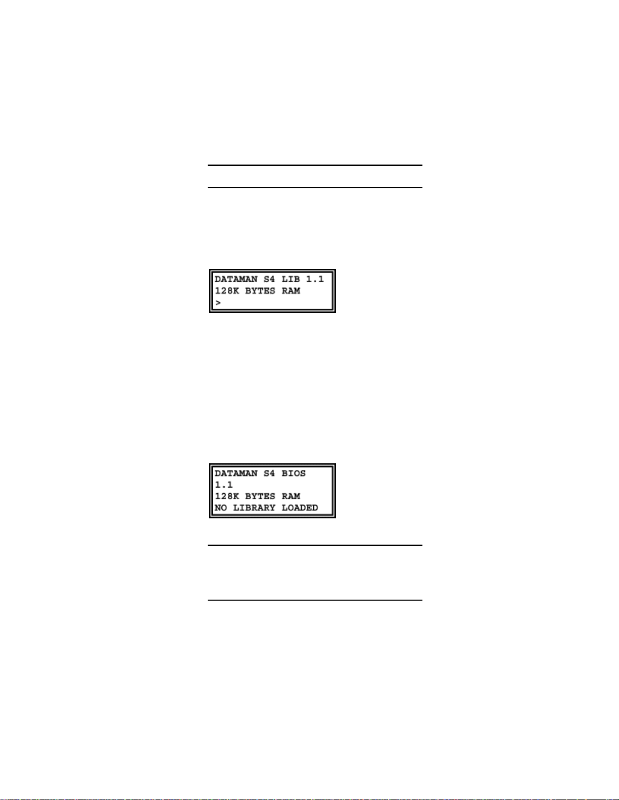
Confirming that S4 works
Switch on and rotate the display thumb-wheel
away from you to its full extent, which darkens
the display. Adjust for best contrast, which
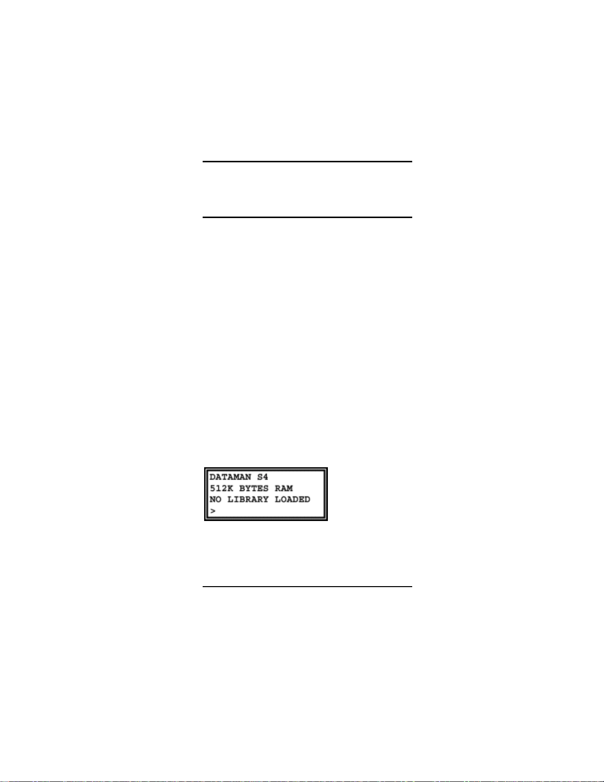
depends on viewing-angle and temperature. If
a LIBRARY program is loaded, S4 will display
the version number:
If you see this message then you may carry on
and use S4. Store the LIBRARY ROM
somewhere safe, in a piece of conductive foam.
If there is nothing in the display turn up the
contrast by rotating the thumbwheel on the left
of the display away from you to its fullest extent.
If still nothing, perhaps the battery is totally
discharged. Plug the charger in with the
RESET button depressed and hold it in for a
few seconds. When you release it you will see
a message:
Loading the LIBRARY ROM
Reloading S4's software program from
LIBRARY ROM is not something you should
need to do to a brand new product. In fact you
should never need to do it at all, except when a
Introduction to S4 3
Page 4
DATAMAN S4 MANUAL
new version of the working program is to be
loaded.
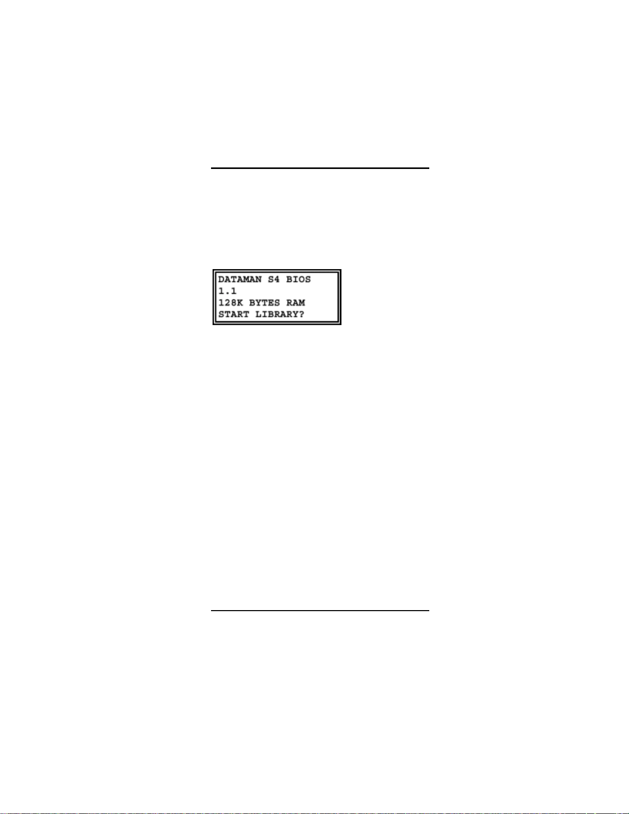
The procedure is as follows: press the RESET
button by pushing the write lead plug through
the hole in the case above the ON/OFF switch.
(No force is needed - it is only a push button!)
You will see this message:
You will notice that the version of LIBRARY is
not identified, because there is no LIBRARY
program loaded. If S4 sees what it thinks is a
valid library it will ask you if you want to run it.
ESC = NO
ENTER = YES
If you do want to load a new library press ESC
then LIB.
Put your LIBRARY ROM in the socket and
press ENTER.
S4 will load the program contained in the
LIBRARY ROM. Then it will restart and run the
program. If the LIBRARY program loads
correctly, S4 will introduce it and display the
version number.
When the RESET button is pressed, S4 returns
to low-level BIOS MODE, in which it will only
program LIBRARY PROMS of the 27256
variety. It is not intended that you should use
S4 in BIOS MODE without a library loaded.
Note: In theory you will never need to load
the LIBRARY program. It will be present in
4 Introduction to S4
Page 5

DATAMAN S4 MANUAL
memory when you buy your S4 and it will
remain there, because S4's memory is
permanent and continuous for both
programs and data.
The only reasons for loading a LIBRARY are to
upgrade to a new version or to reload your own
custom version of the library, with your
preferred defaults, after somebody else has
used your S4 and changed the settings.
RESET & BIOS Mode
If RESET is pressed S4 returns to a program
running in the masked ROM of the
microcontroller this is called the BIOS (Basic
Input/Output System). Whilst S4 will run in this
BIOS mode and obey most instructions, it is
not intended to be used without a LIBRARY
loaded into the TPA (Transient Program Area).
The BIOS contains subroutines which are used
to handle input and outputs - RS232, Keyboard,
Display etc. BIOS mode is used only for
development of new library programs. In BIOS
mode, S4 will only program a 27256 EPROM,
of the type used as a LIBRARY ROM.
This section is written for sake of
completeness - it is unlikely that anyone
not developing new software for S4 will
want to use the BIOS mode.
Whilst the RESET key is down and the charger
attached, charge is forced into the battery. This
gives a "Jump Start" facility for batteries which
are absolutely flat.
Introduction to S4 5
Page 6
DATAMAN S4 MANUAL
S4's microprocessor and RAM have power on
all the time. When S4 is switched on, it
awakens from a SLEEP MODE and starts
operation at the address pointed to by the
Warm Start Vector (WSV). Loading and
running a library reloads the WSV so that S4
starts operation in the right place. Pressing
RESET points the WSV back into the BIOS but
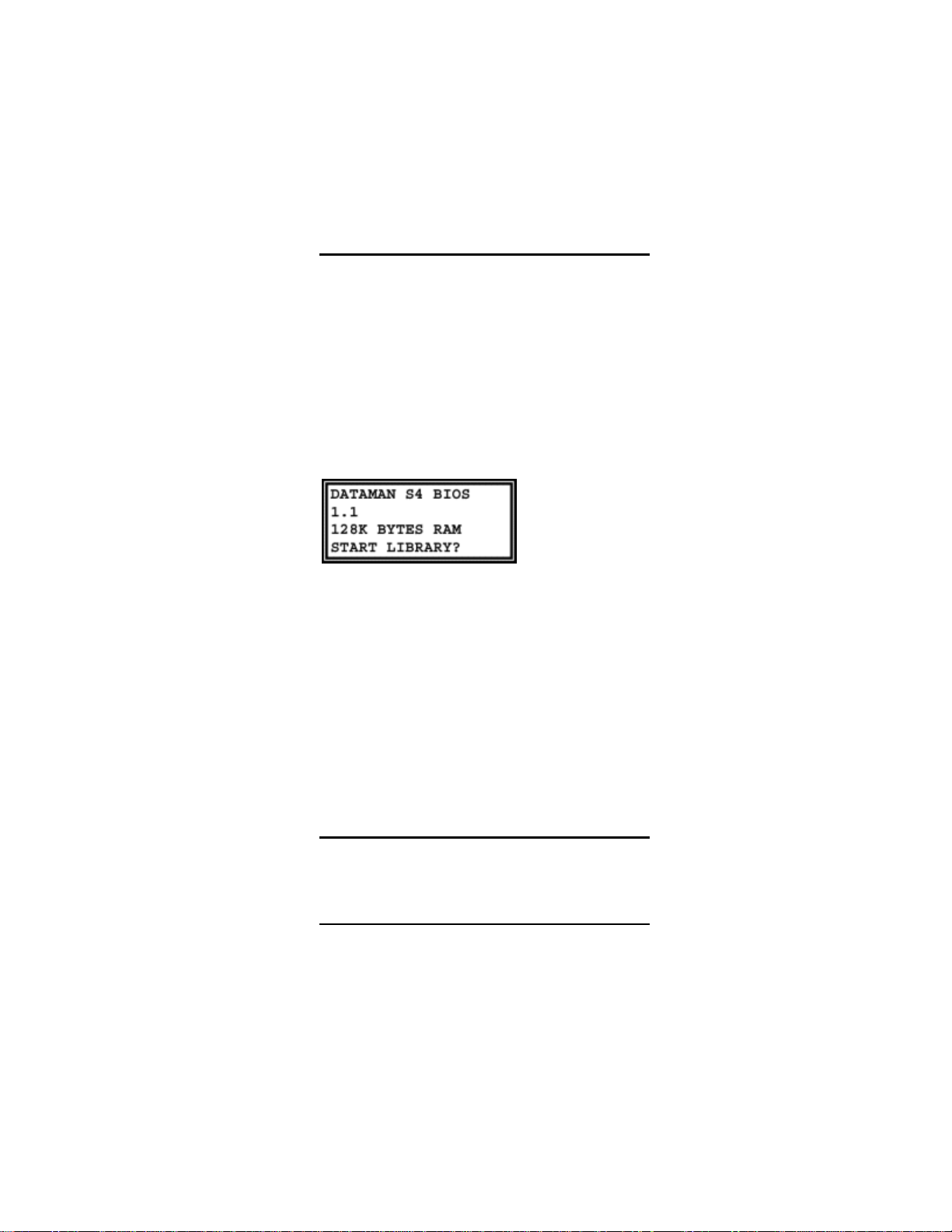
it first looks at the TPA . If the program thinks it
sees a valid library, it will ask you whether you
want to run it:
ESCape will do a COLD START into the BIOS.
ENTER will run the library.
If you want to reload your LIBRARY ROM,
place it in the ZIF socket and press LIB.
The LIB key loads a program into the Transient
Program Area from 8000 to FFFF, from a ROM
in the ZIF socket. The LIBRARY ROM must be
recognized by the system as a valid library. A
ROM which does not contain a LIBRARY will
not load. The BIOS configures S4 to handle a
27256, so the LIBRARY ROM must be a
27256.
Automatic Power-down
If there is no charger connected, S4 goes to
sleep if there is no input for 30 minutes. It turns
the display off and enters a powered-down
mode. For the last 30 seconds it makes
6 Introduction to S4
Page 7

DATAMAN S4 MANUAL
beeping noises. It will switch itself off at the
end of this time. If you press a key during the
beeping, power-down is prevented. No data is
lost by power-down, but you have to switch-offand-on-again to get the power back.
If a charger is connected, S4 remains on. If the
battery runs down to the 25% point, it is
automatically recharged.
S4 also powers down when it believes that the
battery is getting too low - less than 8.4 volts.
At this level, data and program can be
preserved, but nothing else works. It warns you
first, both audibly and with a message. If the
voltage goes below 8 volts it turns off
immediately without warning. S4 cannot do
anything useful without power, except preserve
the memory contents.
The only cure is to charge the battery.
Memory Upgrade to 512K
At some point, you may wish to upgrade the
user RAM in your S4 from 1Mbit to the full
4Mbit (512K bytes). All Dataman sales offices
keep a suitable part in stock, or you may wish
to purchase it through a local memory vendor.
The correct part should be a 4Mbit (512K x 8)
low power static RAM in a 32 pin JEDEC DIL
package. We recommend fitting a part with an
access time of 100ns or less.
The upgrade procedure is simple. First switch
off then:
1. Remove the back of the case by
unscrewing the four retaining screws
Introduction to S4 7
Page 8

DATAMAN S4 MANUAL
2. Remove the 1M static RAM chip from
its socket.
3. Substitute a 4M static RAM chip or
module.
4. Replace the back of the case and the
screws.
When you switch on, S4 will now tell you that
you now have 512k of memory instead of 128k.
The ZIF Socket
The ZIF (Zero-Insertion-Force) socket is used
to load new library programs into the TPA
(Transient Program Area) as already described.
The ZIF socket is also used to hold PROMS
when programming. S4 can use PROMS much
the same as a computer uses a disk-drive: they
are a permanent storage medium, which
contains programs to be loaded into system
RAM - such as the program loaded from the
LIBRARY ROM.
When the socket is not being addressed, no
power is applied to it. PROMS can be inserted
at any time, except during an operation like LIB,
LOAD, BURN, TEST, SUM or COMP, which
read the PROM. When S4 is waiting for a
command, or performing any function which
does not involve reading a PROM, the socket
is "cold" – it has no supply voltages. Even
when the socket is being addressed directly, it
is only powered-up for sufficient time to read
the data
Note: PROMS with 24 pins or 28 pins must
be inserted at the b ottom end o f the socket
8 Introduction to S4
Page 9
DATAMAN S4 MANUAL
the upper pin-sockets of each side should
be empty.
Terms and Basic Concepts
The message ESC in the display means that
the ESC key was pressed during or before
execution; the previous command was not
completed or maybe not even started.
The ZIF means the Zero-Insertion-Force
socket on the front panel.
The Keypad refers to S4's 45 keys. Key repeat
is automatic, when a key is held down. The
delay after the first entry is longer than that
after subsequent entries, to prevent false
repetition. When data is being entered by
repetition, the flashing block cursor changes to
a steady underline cursor, so that progress is
easier to follow.
The Screen means the remote terminal screen.
The Display means either the terminal screen
or S4's liquid crystal.
The Keyboard refers to the remote terminal.
The LCD is S4's own Liquid Crystal Display.
Outputs are shown boxed in the text, meaning
that this is literally what you will see:
The Command Line means the display line
which starts with a prompt >.
An operation will be performed if you press
ENTER or be aborted if you press ESCape.
Introduction to S4 9
Page 10
DATAMAN S4 MANUAL
ESCape Commands which are non-destructive
(do not change anything) are actioned as soon
as you press the key, without waiting for
ENTER
A Digit is always Hexadecimal - not Decimal
An Address defines one location in memory
(expressed as 5 digits)
A Parameter is a set of Digits, two for a Byte,
five for an Address
A Block means contiguous bytes of memory
from Start address to End address inclusive. If
three parameters appear the last is the
Destination address.
Backspace and space are used to edit
parameters in the command line from the
terminal keyboard, equivalent to
on the keypad. X and Y are equivalent to
.
and
ESC aborts a command, even if it is already
running. That part of the command which is
already done cannot be undone, of course.
ENTER (or RETURN) accepts a command as
seen.
ESCape or ENTER may be pressed anywhere
in the command line. If the parameters have
been altered, ENTER accepts them as seen
but ESCape restores the originals.
Where there are three parameters in the
command line they are in the following order
START, END, DESTINATION. Each parameter
is five hex digits.
and keys
10 Introduction to S4
Page 11
DATAMAN S4 MANUAL
The START and END addresses normally
define the whole PROM. They can be edited to
limit the effect of functions to less than a whole
PROM.
When editing the START address, if the
keys are pressed, then the START and END
addresses will change automatically to new
boundaries.
If the START address is changed to fall outside
the current boundary then the END address
changes automatically to the end of the new
boundary.
If either the START or the END address is
moved away from the boundary, the = (equal)
sign will change to a # (not equal).
S4 refuses to accept a value for the END
address outside the current PROM size.
If the configured PROM is bigger than the
available memory, then the sign before the
DEST address will always be #. In this case it
is not possible to handle the whole PROM in
one pass. The DEST address, may be edited
with the
blocks which can be handled separately.
and keys to divide the PROM into
or
Only one set of START, END, DEST
addresses are stored and shared between
those functions which use these parameters.
Pressing the ESCape key when editing the
parameter line aborts the command, but leaves
Introduction to S4 11
Page 12

DATAMAN S4 MANUAL
the START, END, DEST as seen - it does not
restore their original values.
Paged EPROMS e.g. 27513
A Page has a special meaning for EPROMS
like the 27513, which is divided into pages of
16K bytes. S4 handles page mode EPROMS
as if they had straightforward contiguous
memory. Swapping pages is handled "behind
the scenes" without troubling the user.
Thus there is no apparent difference in the way
S4 handles a 27512, which is one single block
of 64k bytes, and a 27513, which is 4 pages of
16k bytes.
The user must be aware of the real difference,
however, and how it affects his system. Use of
these devices is described in manufacturer’s
literature.
FUNC Key
The FUNC key is used like a shift key to
access an extra set of functions. When waiting
for a function the prompt becomes * instead of
>.
Audible Tones
S4 makes a variety of beeping noises:
A single tone is made on acceptance of a key.
A double tone low-high is a rebuke that a key
is not acceptable.
During the execution of those commands
which take several seconds, "pips" are emitted
every half-second to tell you that the program
is working - except in the BURN routine, which
writes addresses to the display.
12 Introduction to S4
Page 13

DATAMAN S4 MANUAL
An incoming data-file makes a recognizable
sound.
The ADVANCED SETUP has variables which
can be modified to change the tones made by
the beeper.
Introduction to S4 13
Page 14
DATAMAN S4 MANUAL
Computer Operation
There are two ways of using S4. The obvious
way is to enter commands by pressing keys
and reading the 80-character LCD. The other
way is to attach an RS232 interface lead and
enter commands from your computer and see
the results on the screen. There are
differences between Stand-alone and Remote
operation, but each key on S4's keypad has an
equivalent two character serial command. S4
always responds to the requesting device:
keypad commands produce responses in the
LCD, computer commands produce screen
responses. S4 will respond to either device
from the command prompt; no switching of
modes is necessary. If you disconnect the
RS232 interface during a command it may be
necessary to switch-off-and-on-again to regain
control at the keypad.
Once a function has been entered from either
the computer interface or the keypad, the other
device is ignored, until S4 returns to the
command prompt >.
14 Computer Operation
Page 15

DATAMAN S4 MANUAL
Interfacing with a Computer.
Almost every S4 user will need to make a
serial link with a computer at some time.
Computers usually have a serial port, through
which file transfers can be made, in much the
same way as files can be transferred between
disks. In fact the operating system file-copying
routines can specify the serial device: MSDOS
uses COM1: or AUX:, CP/M refers to RDR:
and PUN: for example the command to transfer
a file to S4 from an IBM-type PC is:
The baud-rate, word-length, stop-bits and
parity setting must have been set previously to
the correct values. The command to do this is:
S4 must be set similarly, and the file-format
must expect, in this case, an Intel HEX file
which is decoded as it is received.
Downloading files from the operating system is
likely to work with no handshaking problems,
because S4 will receive any file at full speed.
Sending files back is often not so easy.
Computers seem to implement handshaking
properly on output, but not on input. It is
surprisingly difficult to get any information on
this subject: the manufacturer's data tells you
the names of the signals, but does not tell you
that they do not work. Experiments show that
the input buffer overflows at some point,
Computer Operation 15
Page 16

DATAMAN S4 MANUAL
usually at 64K, when the system transfers the
buffer contents to disk. 64K characters is not
64K bytes, because a HEX file contains two
ASCII characters for every data byte plus
addresses, checksums and other odds and
ends. In fact it is more like 26K bytes. For small
PROMS this is enough. It is possible to send
the whole 64K as 3 chunks, then patch it
together with a word-processor and take out
the two spurious End-of-File lines.
A much better solution is to use some kind
of COMMS or TERMINAL program.
Terminal Emulating Programs.
A TERMINAL sends the information you type
at the keyboard through the serial port. It
displays what comes back through serial port
on your screen. When S4 is connected to your
computer running a terminal program, it might
seem that what you type appears on your
screen: that is not so. What your see is what
S4 chooses to send you in response:
sometimes this is what you typed: sometimes it
is not. Terminal programs usually let you send
and receive files as well, with handshaking
properly implemented, and that is all that is
required for complete control of S4.
S4 DRIVER.
Dataman supplies free terminal software for
your PC for use with S4. S4DRIVER has online
help and will work at speeds up to 115200
baud.
16 Computer Operation
Page 17

DATAMAN S4 MANUAL
File Formats.
S4 sends and receives orthodox computer files.
Only a programmer with an unusual amount of
patience would wish to enter a large quantity of
code into S4 by keying it in hexadecimal
numbers. Microsystems have in the past been
developed by "hand-assembly": the translation
of microprocessor instructions into machine
code mentally without benefit of an assembler,
writing the instructions into memory in
hexadecimal using a keyboard and repetitively
trying out the program until it works. Most sane
programmers these days, who want to stay
sane, would use an assembler which permits
the entry of code as instruction-mnemonics.
The assembler creates a file of machine-code
automatically, but the file is not usually
actionable code. Actionable object code which
is placed in memory exactly as it is received is
called BINARY format. Transmission formats
usually have a certain amount of extra
information, for example the ADDRESS to start
loading the data, CHECKSUM bytes to validate
transmission etc. S4 receives files in common
formats which are output by assemblers;
formats such as INTELHEX, MOTOROLA S,
TEKHEX, ASCII or BINARY and translates
these into actionable object code which is
stored in the USER RAM.
Computer Operation 17
Page 18

DATAMAN S4 MANUAL
Getting Started Quickly
A guide for those who do not want to read the
manual.
Copying an PROM
If you want to make copies of a master PROM
into blank PROMS of the same type, you must
go through four stages:
1. Configure S4 for the PROM type
2. Load the MASTER PROM into S4
3. Test that the new PROMS are blank
4. Burn the new PROMS
Configuring a PROM.
1. Place the MASTER PROM in the
socket with the notch at the top. If it
has less pins than the socket make
sure that it is at the bottom.
2. Press PROM. Choose the
manufacturer with the
Then choose the right part number
with the
when the correct part number is shown
in the display.If you have a data sheet
check that the programming voltage
shown is correct.
3. Press LOAD. S4 defaults to copying
the whole PROM into the bottom of
memory. If that is what you want press
ENTER, otherwise modify the
parameters.
4. The verify that the data has loaded
correctly press COMP. S4 will
compare the data in the PROM with
and keys. Press enter
and keys.
18 Getting Started Quickly
Page 19

DATAMAN S4 MANUAL
the data you have just loaded into
RAM. If it matches you will see the
message SAME.
5. Put a fresh PROM that you want to
program into the socket. If it has a
different part number then you must
reconfigure.
6. Press TEST. S4 will report whether the
PROM can be programmed If the
message "WILL BURN" or "BLANK
PROM" appears then all is well.
Otherwise you must erase the PROM.
FLASH devices can be erased with
FUNC BURN.(press FUNC first, then
BURN). EPROMS with a window need
a dose of UV light from an eraser.
7. Press BURN, then ENTER. The
parameter line of numbers can be
modified if you do not want to burn all
of the PROM, but that is unusual. The
time taken to program the PROM
varies from a few seconds to a few
minutes.
8. It is a wise precaution to take the
checkSUM of the master PROM and
the copies. CheckSUM will help you to
identify an unlabelled PROM.
Getting Started Quickly 19
Page 20
PROM KEY
DATAMAN S4 MANUAL
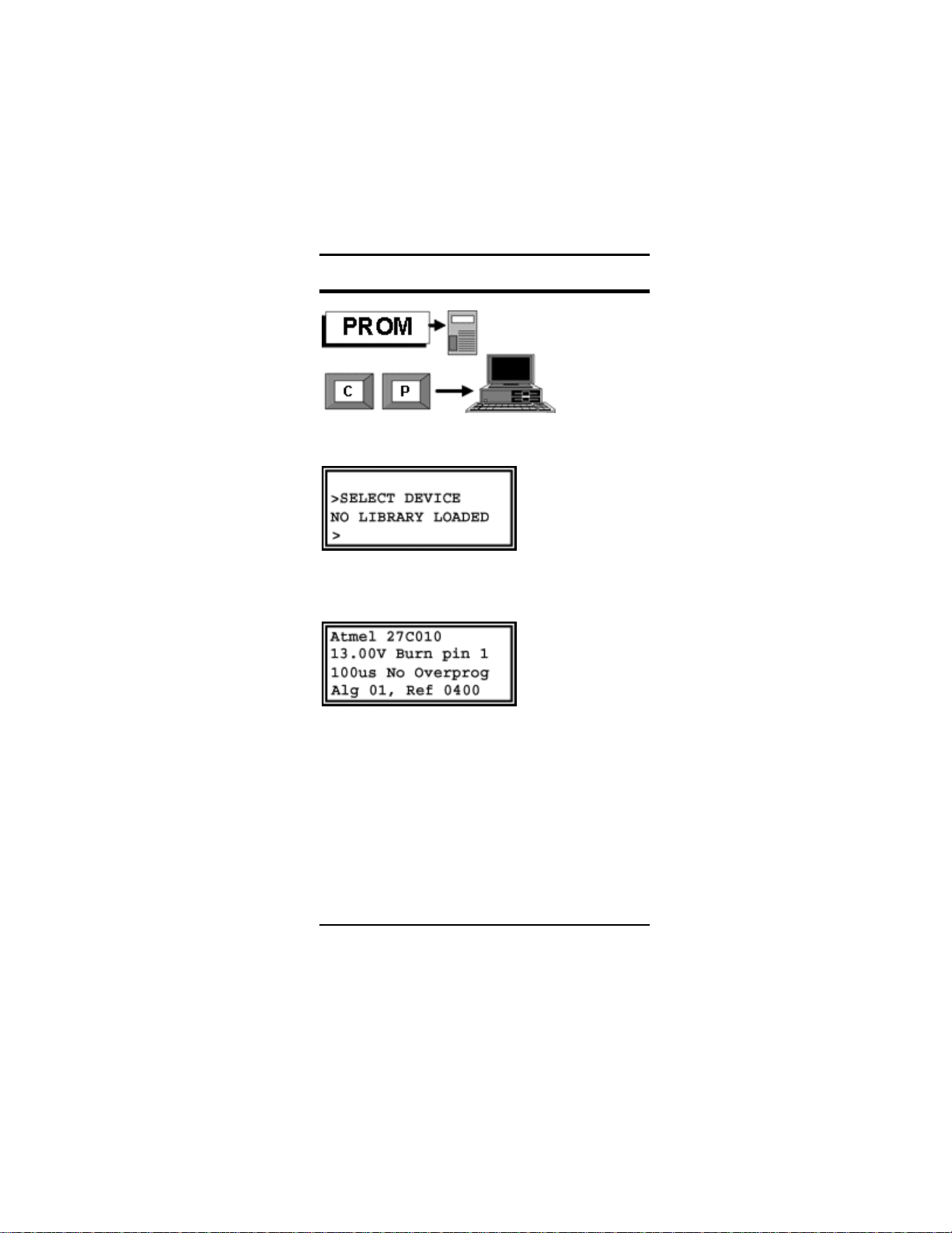
If you get a message on this key which says:
Then S4 will not program any PROM but
27256. You should load the library.
To configure S4 to read and program a PROM
correctly, do one of the following
1. If you remember the Ref number of the
algorithm, enter it. The number is
shown when you scroll through the
ALGORITHMS as described below.
The Ref number is not guaranteed to
be the same in different versions of the
library.
20 PROM KEY
Page 21

DATAMAN S4 MANUAL
2. Use the and keys to scroll though
a list of manufacturers, and then the
and
device (At a remote terminal, use X, Y,
SPACE, BACKSPACE). You have to
know the part-number and preferably
the program-voltage of the PROM - if
you are unsure, get a data sheet from
the manufacturer. S4 will apply the
voltages shown to the PROM in the
socket - if they are incorrect the device
may be damaged. If you really must
experiment, try algorithms which apply
the lowest voltages first.
3. From the “>” prompt, press FUNC-
PROM or at the Terminal type SS. This
invokes the Silicon Signature routine,
which reads a code from the EPROM
in the ZIF socket, and selects the
correct device automatically. This is
the quickest and easiest way to
configure S4, but it should be used
with caution on older EPROMs. This
is because older EPROMS may not
have a Silicon Signature code. The
method used to read the Signature is
to raise address line 9 to 12 volts, and
then to read locations 0 & 1 of the
EPROM. Applying 12 volts to an
address line of a device that does not
have a Silicon Signature could
potentially damage the device.
However, it would be unusual for a
modern EPROM not to have a Silicon
Signature.
keys to choose the actual
PROM KEY 21
Page 22

TEST KEY
DATAMAN S4 MANUAL
PRETEST (START)-(END)=(DEST)
See Glossary for the special ways of editing of
the parameter line.
PRETEST compares a PROM in the ZIF with
the contents of the USER-RAM between the
START and END addresses. The purpose is to
check whether EPROMS must be erased with
UV light prior to programming. Bits are erased
all high, and may only be programmed from
high to low. The first location which cannot be
programmed is reported. If a PROM contains
locations which are already programmed, but
the PROM will accept the new program, the
message WILL BURN is displayed If the
PROM is actually blank it contains all FF bytes
- then the message BLANK ROM is displayed.
S4 must be configured for the right type of
PROM. A warning message gives the PROM
type.
To start the PRETEST, press the ENTER key.
22 TEST KEY
Page 23

DATAMAN S4 MANUAL
The example given will PRETEST a 2764,
addresses 00000 to 01FFF to see whether it
will correctly program with the contents of
USER-RAM addresses 08000 to 09FFF.
TEST KEY 23
Page 24

LIB KEY
DATAMAN S4 MANUAL
LIB is used to COPY new software from a
"LIBRARY ROM" in the ZIF socket to the
Transient Program Area. The program runs
automatically when it has loaded.
When you see the message, place a LIBRARY
ROM in the front panel socket and press
ENTER. To abort the command, press
ESCape.
The LIBRARY instruction does not move all the
code in the LIBRARY ROM into the TPA area:
if it did the stack would be overwritten in the
process and the program would crash. Instead
the ROM contains pointers which show which
code must be moved. Each pointer is prefixed
by a 42 byte: 42 is used to indicate that there is
a block to be copied (Why 42? Well, any byte
could be used and 42 has no real significance,
except to the software engineer who is a
Douglas Adams fan....) The four bytes
following give START and END addresses of
the block. If there is another block then follows
24 LIB KEY
Page 25

DATAMAN S4 MANUAL
another 42 byte, followed by another START
and END, and so on. When the LIBRARY
program has been loaded, S4 resets and runs
it.
At the end of the table of blocks there is a byte
which is not 42. If this byte is 00, 54 then S4
picks up the following two bytes as a start
address and executes it. If it is not 00,54 then
S4 returns to the command prompt.
LIB KEY 25
Page 26
SETUP
DATAMAN S4 MANUAL
This key has no terminal equivalent. File type,
baud rate and handshake have separate
terminal commands.
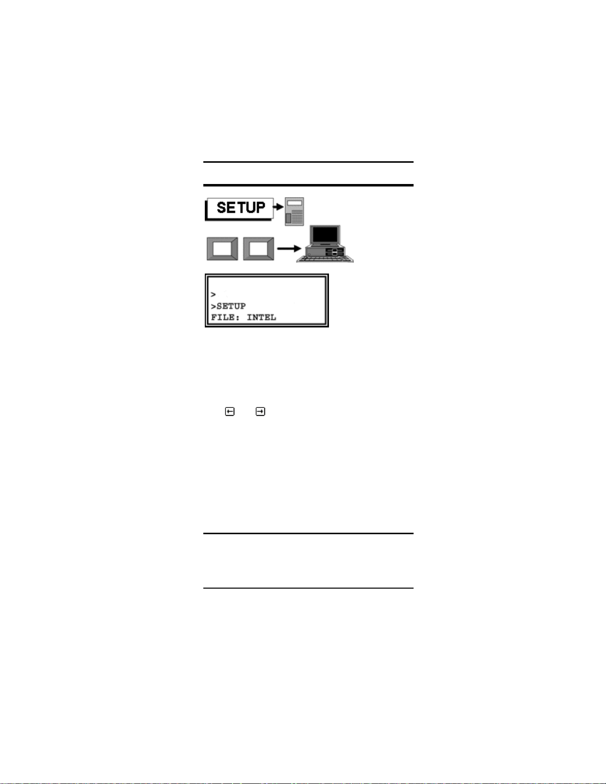
The SETUP routine sets the FILE TYPE
RS232 BAUD RATE and HANDSHAKE, in that
order.
Use
and to see and select options.
It is possible to ESCape at any point but any
changes stand – the settings do not revert to
original values. Remember WYSIWIG – What
You See Is What You Get. If you read
something in the display, then it is true.
Therefore it is not necessary to proceed to set
up BAUD RATE just to change the FILE
FORMAT.
File Type.
S4 will receive files serially transmitted in a
standard format. The formats supported are
INTEL, MOTOROLA, TEKHEX, ASCII and
26 SETUP KEY
Page 27

DATAMAN S4 MANUAL
BINARY. A detailed description of each format
is given later.
The
formats and set-up the one displayed. You
must leave the right format in the display –
what you see is what you get, even if you
press ESCape instead of ENTER.
and scroll through the different
Baud Rate & Handshake
Baud rates of 300, 600, 1200, 2400, 4800,
9600, 14400, 28800 or 115200 may be chosen
The
and keys scroll through the choices,
and you may use ESCape or ENTER to
complete the set-up. Auto-selection of Baud
Rate is possible too. At this point, if your
computer is running a COMMS program in
terminal mode and is attached to S4 you can
set baud-rate by pressing the SPACEBAR on
the computer's keyboard.
If handshaking on outgoing transmissions is
required, it can be set RTS or DTR.
If S4 is powered off, the handshake will be
reset to NONE when it is switched on again, if
no valid handshake can be seen. Otherwise
S4 would hang-up waiting to send the
introductory message.
SETUP KEY 27
Page 28
INFO KEY
DATAMAN S4 MANUAL
This is a keypad only command: there is no
terminal equivalent.
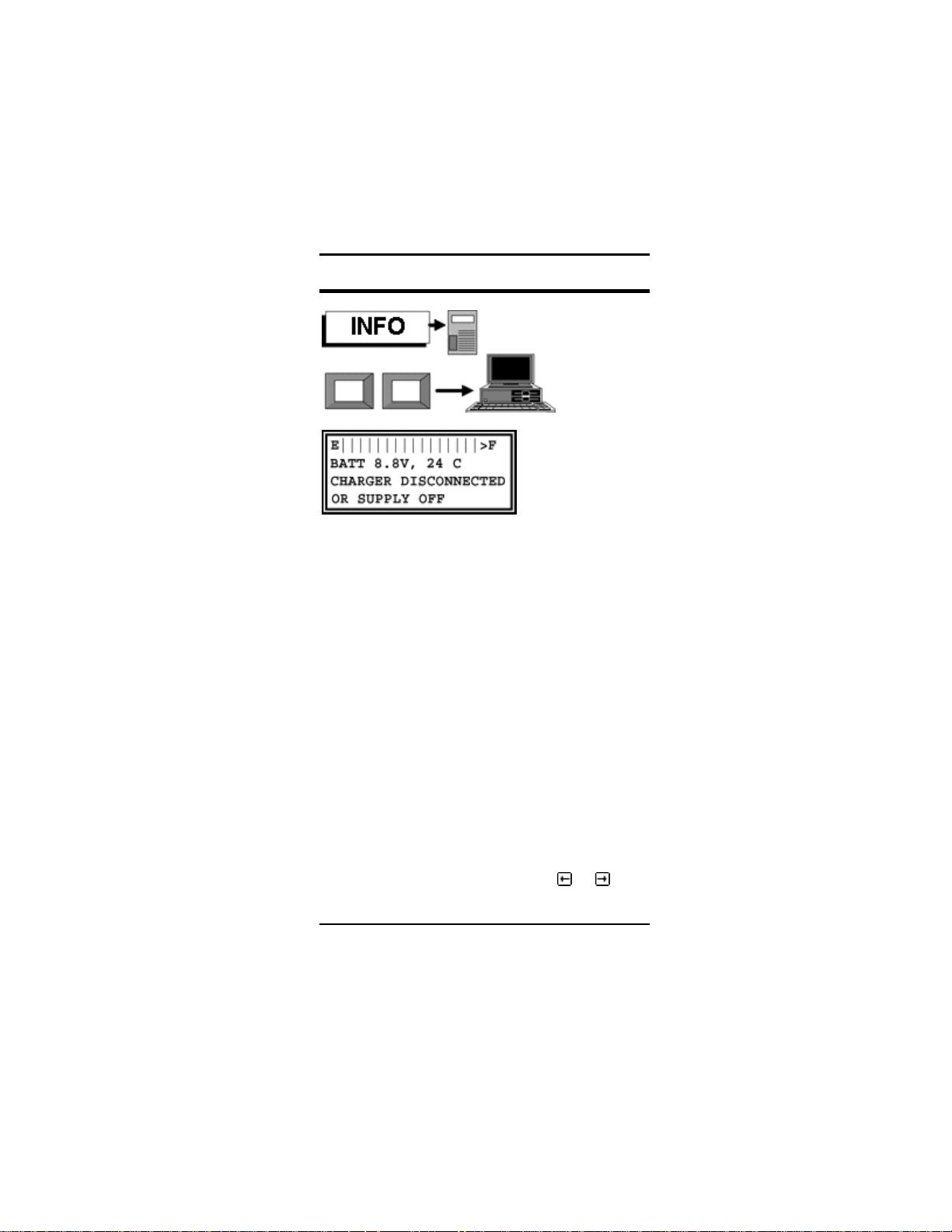
INFO displays and continuously monitors
battery voltage and temperature, and tells you
whether the charger is connected and turned
on.
The charger normall y looks after itself an d
it needs no assistance.
S4 is powered by a rechargeable battery of 7
nickel cadmium cells providing 8.4 volts
600ma/hr. Charging is automatic: you do not
have to turn the charger on or off.
The charger turns on automatically when the
FUEL GAUGE indicates that battery is less
than 25% charged.
You do not have to switch the charger on or
off deliberately, but you can do so if you
wish in INFO mode by pressing
or .
28 INFO KEY
Page 29

DATAMAN S4 MANUAL
If the charger is attached and switched on, you
will see the battery voltage rise as the battery
charges. When the battery is fully charged you
will see the temperature rise and the charger
will switch-off when the rise equals 5°C.
One CHARGE is enough. It is possible to
raise the battery temperature by charging
three or four times in succession, which
raises temperature by 5°C each time. This
does not put any extra charg e in the bat te ry
or achieve anything useful.
To terminate INFO mode, press ESCape.
Automatic Battery Charging
When S4 is turned on, it charges the battery if
the "FUEL GAUGE" shows less than 75% full.
The charger will replenish the battery in less
than an hour. There is a temperature sensor in
contact with the battery. When it sees a 5°C
rise, the charge current turns off. Charging is
thus perfectly safe and S4 may be used
normally whilst being charged.
The internal circuitry prevents the batteries
overcharging. While capacity remains they are
capable of absorbing high currents, but when
fully charged the current is not stored - it is
dissipated as heat. S4 monitors battery
temperature, looking for a 5°C rise at which
point the high current is turned off. S4 remains
on when charging - but will turn itself off
automatically when the job is done. You can
safely leave S4 alone when charging or
continue to use it. If the message HEAT
appears when charge is requested, it means
INFO KEY 29
Page 30

DATAMAN S4 MANUAL
that the temperature is too high or too low to
be monitored. (below 5°C or above 45°C). The
method used for detecting temperature is to
measure the voltage across a thermistor, which
is in physical contact with the battery, which
does not make an accurate thermometer - but
it is good enough to observe a 5 degree rise.
S4 does not permit fast charging of batteries
which are outside the 5 degree and 45 degree
limits, because battery manufacturers do not
recommend it.
The Fuel Gauge
Across the top of the display is a bar-graph
showing S4's estimation of remaining battery
capacity. This really is an estimation: it is not
possible to measure charge in a Nicad by
looking at its voltage or by any other means.
S4 keeps track of power usage from the last
fully charged state. The FUEL GAUGE
represents S4's guess at how much charge
remains. It isn't perfect - but it's a lot better
than no guess at all. The FUEL GAUGE will be
wrong in the following circumstances:
1. If the battery was changed or removed
2. If S4 has been switched off for a long
time. (that's because S4 cannot
estimate self-discharge).
In either case the FUEL GAUGE will
correct itself when the battery is charged.
30 INFO KEY
Page 31

DATAMAN S4 MANUAL
Nicad Battery
The battery is capable of the following typical
performance when fully charged:
• Standby 10ua - about 12 week’s
retention of program, data and
configuration. After that the Lithium cell
takes over.
• Viewing 30ma - 20 hours of editing
(25% less via RS232)
• Burning 180ma - 3 hours
programming - the actual number of
PROMS varies widely from about 100
oldest-type to 1000 latest-type
• Emulating 100ma - 6 hours emulating
(depends on amount of access that the
target system makes and the load it
places on the data lines).
Real work is a combination of activities, of
course.
Early warning of battery discharge and
automatic shut-off operates if the battery falls
below 8.4 volts. Shutting-off is orderly - there
is no harm to any device being programmed
and no loss of data, provided S4 is recharged
within a few days.
When the charger is ON, 650ma a.c flows into
S4 and this will recharge the battery in about
an hour. A reasonable working capacity will be
restored in much less time.
Deep discharges and fast recharges make the
battery last longer than a trickle of charge
which maintains a fully charged battery all the
time.
INFO KEY 31
Page 32

DATAMAN S4 MANUAL
Lithium Backup Battery
Nickel Cadmium batteries lose capacity by selfdischarging at a rate of 200% per year,
according to the manufacturers. That means
that a fully-charged Nicad today will have no
charge at all in 6 month’s time.
When S4 turns itself off because the battery
voltage is low,, there is less than 1% capacity
remaining. The RAM data might only be
supported for a few days. For this reason, a
Lithium battery has been fitted to support RAM
and microprocessor data when the Nicad loses
its charge. The Lithium cell does not have this
self-discharge problem. The Lithium battery
would last over 10 years in an S4 which was
always charged, and about 2 years in one
which was always flat.
Charging from a Bench Supply.
You can also charge your S4 from a D.C.
bench supply. However this needs caution. S4
is not capable of turning off the D.C. charging
current; so this must be limited to what the
battery would take continuously without
overheating - 60ma. is safe. The D.C. positive
and negative connections can be either way
round because there is a bridge in the charging
circuit.
Avoid emulating and charging from a
bench-supply at the same time. There could
be a conflict between system grounds.
32 INFO KEY
Page 33

DATAMAN S4 MANUAL
Defective Battery
NICAD manufacturers claim that "deep cycling",
meaning full charges and discharges, is good
for the battery; apparently this discourages
physical change, the formation of dendrites,
which cause premature failure.
Electronics lore is that Nicads "learn" the
capacity that their job requires and refuse to
hold more charge. Some authorities claim this
is not true and at Dataman we have never
observed this effect. What we have seen is
that there is a low but constant rate of failure in
Nicad cells which is not dependent on age.
New ones seem to fail occasionally - as often
as old ones. They seem to do better if worked
hard, i.e. charged and discharged quickly.
The symptoms of a defective battery are that it
does not reach normal output voltage. Nicad
cells usually fail by going short. If one of the
seven Nicads cells is short, the battery will
charge to temperature cut-off but remain below
9 volts, because it only has 6 cells instead of 7.
The combination of high temperature and low
voltage can be observed in the INFO display.
The battery should be replaced as soon as
possible.
INFO KEY 33
Page 34

LOAD KEY
DATAMAN S4 MANUAL
LOAD (START)-(END)=(DEST)
See Glossary for the special ways of editing
the parameter line.
LOAD copies the contents of the PROM in the
ZIF into USER-RAM. The area copied and the
destination is defined by the START and END
addresses.
S4 must be configured for the right type of
PROM. LOADing memory does not apply
program voltages or program pulses to the
PROM. PROMS of the same size and type
have different configurations for programming,
but they can be read by the same procedure. If
the only difference is the manufacturer and you
intend to copy say, 27256 PROMS, of one
manufacturer into similar blank PROMS made
by another, then it is okay to leave
configuration set to the PROMS you are
actually programming. You need not change
configuration just to read the originals.
34 LOAD KEY
Page 35

DATAMAN S4 MANUAL
A warning message gives the PROM type. If
the ESCape key is pressed the process is
aborted. If the ENTER key is pressed the
process goes ahead.
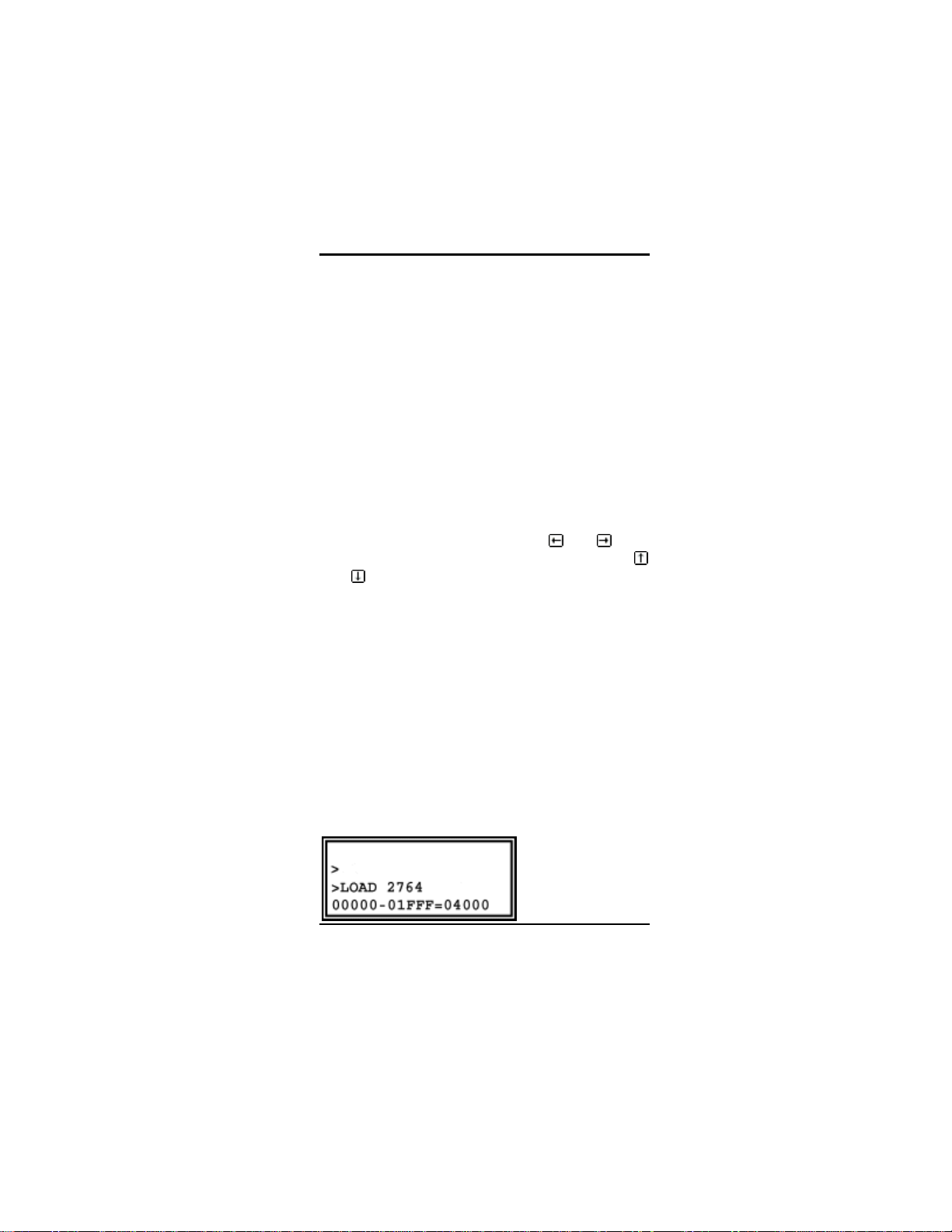
The example given will copy a 2764 in the ZIF,
addresses 00000 to 01FFF to USER-RAM
addresses 02000 to 03FFF.
LOAD KEY 35
Page 36

DUMP KEY
DATAMAN S4 MANUAL
The keypad version of this function is similar to
edit, except that it works directly on the
device in the ZIF socket.
For economy of code we have used the edit
routine. You cannot, of course, change any of
the data.
Terminal Dump Rom
DUMP (DEVICE)
(START),(BYTES)
This is the terminal equivalent to the keypad
function. It uses a full screen display to show
address and data contents, starting at the
address requested for the number of bytes. If
36 DUMP KEY
Page 37

DATAMAN S4 MANUAL
the number of bytes is set to 0, then the dump
will continue until the ESCape key is pressed.
Warning: computers can take a long time
writing data to screen. Unlimited dumps
may eventually cause the computer's input
buffer to overflow and the display to
become fragmented, especially if the baud
rate is high.
DUMP KEY 37
Page 38

SPLIT KEY
DATAMAN S4 MANUAL
Puts all the odd bytes in the top half of memory
and all the even bytes in the bottom half. Split
moves all 64K, (except location 0000 and
location FFFF!)
Using the
SPLIT 128k 256k or 512k bytes.
When a microsystem has a bus which is 16
bits or 32 bits wide, then it will address more
than one PROM in parallel. But the assembler
produces the code in serial fashion, with high
bytes and low bytes alternating. It is possible
that S4 will receive serial code and must put
every other byte in a different PROM. Splitting
the code moves the bytes to a contiguous
block of memory which may be burned directly
into a PROM.
and keys you can also elect to
38 SPLIT KEY
Page 39

DATAMAN S4 MANUAL
How memory splitting works
SPLIT KEY 39
Page 40

SHUFFLE KEY
DATAMAN S4 MANUAL
Shuffle is the opposite of split. The top half of
memory becomes the odd bytes, the bottom
half the even bytes. Every byte in memory is
moved, except the first and last - 0000 and
FFFF.
Using the
SHUFFLE 128k 256k or 512k bytes.
If PROMS are to be loaded into USER RAM
and the code sent to a remote computer
through the RS232 interface, in a 16 or 32 bit
system it must be combined so that the bytes
are successive. This can be achieved by
loading the different PROMS to different blocks
of memory and shuffling.
and keys you can also elect to
40 SHUFFLE KEY
Page 41

DATAMAN S4 MANUAL
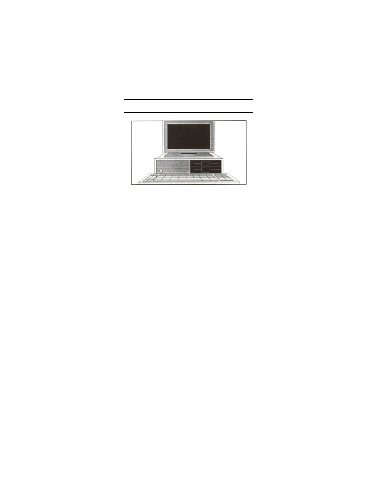
EMULATE KEY
Emulates the
configured PROM.
If the Write Lead is
connected to the
microprocessor
then writing into
USER RAM
through the
EMULead is
possible. The
ESCape key stops
emulation and
returns control to
the keyboard
(other keys may
do the same.)
EMULATE KEY 41
Page 42

DATAMAN S4 MANUAL
Memory Emulation
S4 emulates ROM and RAM, and may be used
to modify or develop code. The emulation-lead
should be plugged into the target system ROM
or RAM socket before issuing the emulate
command. Pin-out configuration of EPROMS is
automatic, Chip Enable and Output Enable
signals are implemented correctly, for JEDEC
27 series EPROMS. This technique is an
enhancement of ROM-emulation - we call it
Memory-Emulation.
EMULate from address zero.
The EMULead causes S4's RAM to behave
like the PROM itself. The target system sees
the zero address in the emulated PROM at the
zero addressin S4's RAM. If the area of
memory which is intended for emulation has
been loaded at a higher address, then it must
be moved (or swapped) to location zero, for
emulation to work.
The pins of the EMULead are routed to the
RAM memory through buffers. When address
00000 and the Chip-Select and Output Enable
signals are applied, the data on address 00000
of the RAM appears on the databus. PAGED
addressing, as in EPROMS like 27513 other
than PAGE 0, is not supported.
It is a frequent complaint that S4 will not
emulate, when the user has loaded say, a
2764 at location 0E000-0FFFF, because that
is where it is add ressed in his p rototype. A
PROM does not know where it is in
addressing space, and neither does S4
42 EMULATE KEY
Page 43

DATAMAN S4 MANUAL
when emulating, because the decoding is in
the target system. In this particular case it
would be necessary to move the code from
0E000 to 00000 before emulating.
Benefits of memory emulation .
1. It is universal. You can use it with any
microprocessor.
2. The equipment costs less than a
Microprocessor Develoment System.
The only other piece of kit you need is
a computer and a cross-assembler.
3. The target system behaves like the
"real thing".
4. The software runs at full-speed.
5. Memory contents can be inspected,
edited and the program started again
very quickly.
6. It is very cheap and effective with
single-chip microcontrollers which
have a piggy-back version. You plug it
straight into the back of the
microprocessor.
7. It is good for making modifications to
existing systems, such as changing
messages and odd values, especially
where some trial and error is involved.
The "tweak values and try it again"
process works very well.
8. When successful the program can be
transferred to an EPROM immediately.
How Memory Emulation works
The method used is to assemble the program
on a computer and download in one of the
standard file-formats into the emulator. The
EMULATE KEY 43
Page 44

DATAMAN S4 MANUAL
Memory-Emulator will do most things that an
Microprocessor Development System can do,
and most MDSs do not have editors and code
manipulators which are as powerful as those of
S4. S4 will not do anything microprocessorspecific – but it is not usually too difficult to
write a routine in the code of the targetmicroprocessor, whereby a subroutine-call or
software-interrupt may be substituted for any
instruction, and the microprocessors registers
dumped to a specific area of USER RAM
where they can be inspected. The
microprocessor in the target system can
WRITE as well as READ. It true that PROMS
do not have a WRITE input, but that is
provided separately on a flying lead.
Microsystem memory selection
In a microsystem, ROM and RAM are selected
by decoding the address bus to derive unique
CHIP SELECT signals. Each chip has its own
slot in addressing space. ROM and RAM
output their data on the system bus when their
address is selected and the microprocessor's
READ line becomes true: the READ line
should be connected to the OUTPUT ENABLE
lines of all chips in the system. The
microprocessor sees no difference between
ROM and RAM, when reading. During a
WRITE cycle the READ line stays false and no
memory chip can output data on the bus. This
prevents conflict with the data written by the
microprocessor. The WRITE output of the
micro is connected to the WRITE input of the
RAM. When the WRITE signal becomes true
the write-data output by the microprocessor is
44 EMULATE KEY
Page 45

DATAMAN S4 MANUAL
written to the location in RAM specified by the
address bus. The micro would happily try to
write to ROM, if required to do so, but nothing
would happen because the ROM has no
WRITE input.
Correct Prototype Design
There are many microsystems around which
are incorrectly designed. A common mistake is
to select the memory chips by their OE inputs
instead of CS. Another mistake is to connect
OE to CS - or even to ground. CS should be
derived from the ADDRESS bus, and OE
should be derived from the READ STROBE.
Systems designed without regard use more
current than they need to. There is a period of
conflict in every cycle, in which both the micro
and a memory chip are enabled on the bus
together, and this causes current surges and
voltage spikes. Some memory parts require
longer access times when recovering from
such conflict. Access time is also worse if the
system does not apply CS prior to OE - access
time from OE is always shorter. ROM
emulation will work in such systems - but RAM
emulation cannot work if the system does not
apply CS without OE - nor would it work with a
real RAM. Chip Select must be TRUE, and
Output Enable FALSE when writing.
Emulating RAM
Byte-Wide RAMS may also be emulated. If the
EMULead is to be plugged into the socket
meant for a STATIC RAM, the PROM
configuration must be set to a PROM which
has similar address and data pin-out. The
EMULATE KEY 45
Page 46

DATAMAN S4 MANUAL
write-line must not be connected through the
EMULead, but must go directly to the Flying
Write Lead. One way to do this might be to cut
the Write-pin off a spare EMULead, used only
for this purpose. Another way is to use an
intermediate socket plugged into the EMULead,
which has the write-pin removed.
Power Usage when Emulating.
The time-out termination is disabled while
emulating, but the low-battery termination still
works. Emulation places an extra current-drain
on the battery: the actual current depending on
the load driven by the data-pins and the
amount of time the internal memory is enabled.
100 milliamps is typical which is about 6hrs on
a full charge. If the charger is plugged-in then
there is no time-limit. The ESCape key will
terminate the emulate mode.
Line Terminations of the EMULead
All the DATA, ADDRESS and CONTROL lines
are connected to logic inputs or outputs of
74HCT series gates via series 150Ω resistors
within S4: this minimizes over- and undershoot without compromising output drive too
much. To prevent the lines floating when
disconnected, which would cause unnecessary
power dissipation, all lines have 100KΩ
resistors pulling then to the 5 volt or ground
rails. To minimize current-drain when
emulating, it is preferable that inputs should be
driven right to the 5v and 0v rails. Drive current
taken from the data-outputs should be kept to
a minimum.
46 EMULATE KEY
Page 47
DATAMAN S4 MANUAL
S4 is impedance-matched to normal drive
conditions, e.g. direct connections to
output buffers. Emulation may not work if
driven with high-impedance lines - via
series resistors, for example.
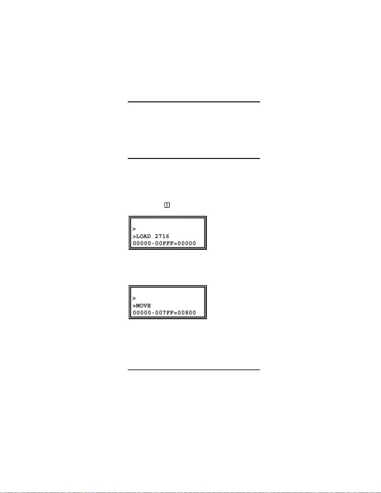
Emulating 2716 EPROMs
Due to a quirk in S4's hardware, 2716
EPROMs must be emulated at address 00800,
rather than 00000. This means that when
loading a 2716 into S4's RAM, which is
intended to be emulated, it must be loaded into
addresses 00800-00FFF. This is achieved by
pressing the
key when in the LOAD routine:
When code is downloaded into S4, it must be
moved to address 00800 prior to emulation.
For example:
EMULATE KEY 47
Page 48
COMP KEY
DATAMAN S4 MANUAL
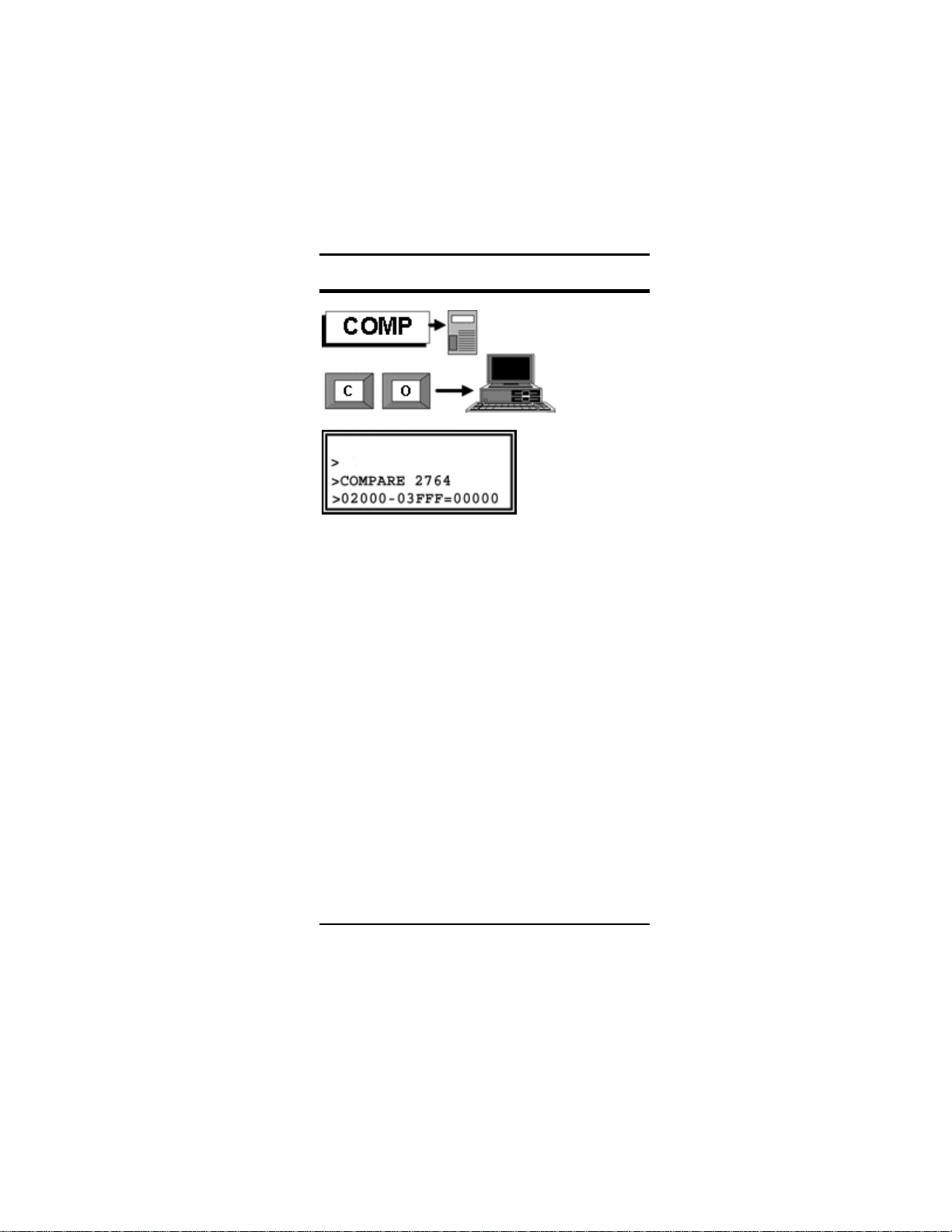
COMPARE (START)-( END)=(DEST)
See Glossary for the special ways of editing
the parameter line.
START and END are in RAM, DEST is in the
PROM.
COMPARE matches all data in the PROM with
the contents of the USER-RAM between the
START and END addresses. Locations which
do not match are reported. If the PROM
matches the block exactly, the message SAME
is displayed.
S4 must be configured for the right type of
PROM. A warning message gives the PROM
type. If the ESCape key is pressed, whilst
editing the parameters, or after any reported
mismatch the process is aborted. To start the
COMPARE, or restart after a reported
mismatch, press the ENTER key. A mismatch
between PROM and USER-RAM is displayed
48 COMP KEY
Page 49

DATAMAN S4 MANUAL
RAM ADDRESS, RAM BYTE, ROM BYTE as
follows:
To display the next unmatched location, press
ENTER. To terminate COMPare, press ESC.
COMP KEY 49
Page 50

DATAMAN S4 MANUAL
SUM KEY (green)
The green SUM key operates on the PROM in
the ZIF socket. It performs a checksum on all
the locations of a ROM in the ZIF socket. The
CHECKSUM ROM function allows the user to
take the checksum of a ROM device without
first loading it into RAM, thus avoiding overwriting USER MEMORY. The PROM TYPE as
specified in CONFIG is displayed. The
CHECKSUM is presented the answer as a
eight digit hex number. A CHECKSUM
provides a "signature" for identifying and
labeling programmed PROMS. Master PROMS
should be labeled with their CHECKSUM to
ensure that they have not been overprogrammed by mistake - and neither gained
nor lost bits whilst in storage. The CHECKSUM
of a device which has programmed wrongly,
gives useful information: if it is too low than the
device has extra bits programmed and was
possibly under-erased. If the CHECKSUM is
too high then the device has bits which will not
50 SUM KEY (green)
Page 51

DATAMAN S4 MANUAL
program - it may be damaged or the wrong
algorithm is being used.
A PROM used as a MASTER to prepare
copies for sale as firmware should be marked
with its checksum. The checksum of the slaves
should be taken and matched against the
master.
SUM KEY (green) 51
Page 52

SEEK KEY
DATAMAN S4 MANUAL
Searches through a block of code from
(START) to (END) for a sequence of up to six
bytes. Bytes are pairs of hex characters, or
"wild" characters, which can have any value.
Wild characters are entered by pressing the
SEEK key again (or terminal X key); they are
represented by X in the seek line. Wild
characters may be used freely for half bytes or
full bytes. The first address which contains
matching data is shown in the display. Press
ENTER to proceed to the next occurrence. Use
ESCape to terminate SEEK. The EDIT key
puts you in the editor at the found address, if
working from the keypad. In any case, SEEK
leaves the last matching address as the EDIT
parameter, so you can EDIT the found data.
52 SEEK KEY
Page 53

DATAMAN S4 MANUAL
MOVE KEY
MOVE (START),(END),(DEST)
Move memory block within USER RAM.
START and END define the block, inclusively.
Blocks can be moved forwards or backwards.
Overlapping causes no problem. The contents
of the original block are left unchanged except where the destination block overlaps.
MOVE KEY 53
Page 54

SWAP KEY
DATAMAN S4 MANUAL
SWAP (START),(END),(DEST)
Exchanges the code in two equal length
memory blocks. The block from hex address
FROM (START) to hex address (END) is
exchanged with a block of same length starting
at hex address (DEST). Swapping overlapping
blocks does not do anything particularly useful,
but you are not prevented from doing it.
Swapping twice with the same parameters will
restore the original code, provided there was
no overlapping.
54 SWAP KEY
Page 55

DATAMAN S4 MANUAL
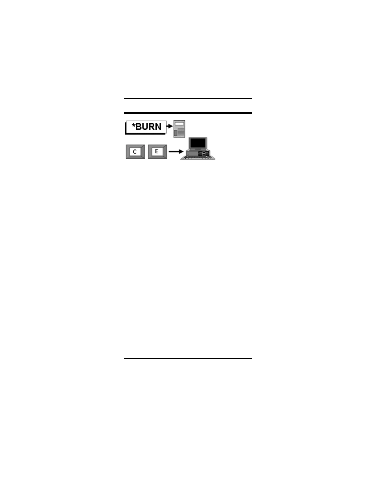
BURN KEY
BURN (START)-(END) = (DEST)
See Glossary for the special ways of editing
the parameter line.
BURN programs a PROM in the ZIF with the
contents of the USER-RAM between the
START and END addresses.
If S4 powers down during BURN, because lack
of battery-power is sensed, the PROM will still
be programmed correctly up to the point where
the program aborted.
S4 must be configured for the right PROM. A
warning message gives the PROM type, the
program voltage and the pin to which it is
applied. If these are wrong, the PROM could
be destroyed. Note that pin number refers to
the PROM. In the case of 24 or 28 pin PROMS
the pin number will be different from the pin
number of the 32 pin socket.
If the ESCape key is pressed whilst editing the
parameters or even after the programming
starts, the process is aborted at that point. To
BURN KEY 55
Page 56
DATAMAN S4 MANUAL
start the BURN cycle, press the ENTER key.
When the cycle is complete, the program
jumps to COMPARE for verification.
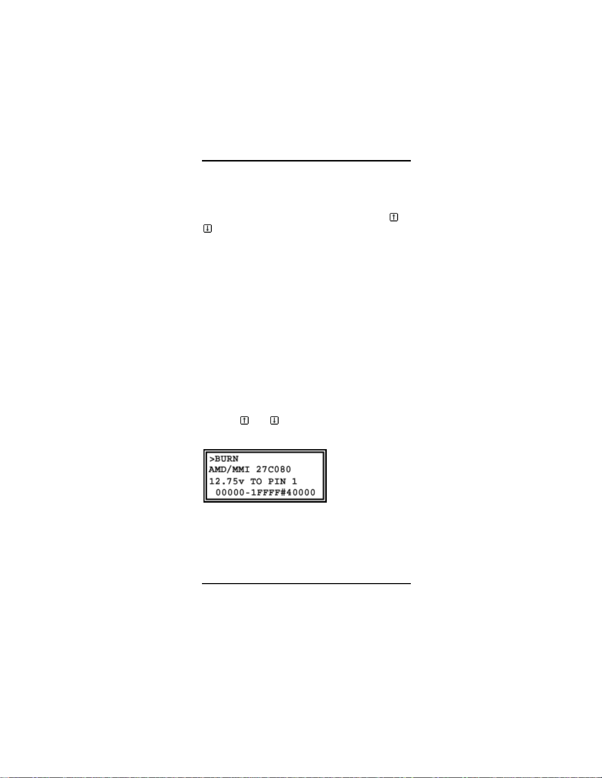
The example given will program a 27256 in the
ZIF, addresses 04000 to 05FFF with the
contents of USER-RAM addresses 04000 to
05FFF. The rest of the PROM is ignored during
programming and subsequent testing.
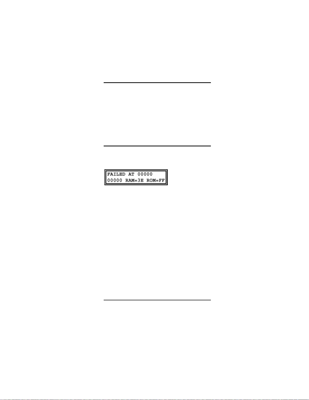
If BURN fails
In the event that BURN fails to successfully
program an EPROM, the following message
will be displayed
S4 will list the locations in the EPROM that
failed to program, and what the RAM & ROM
contents are at those locations. ESC aborts,
and ENTER displays the next failed location.
Here some things to check:
1. S4 must be setup for the right device
type. Press PROM to set the device.
Incorrect configuration can lead to
damaged EPROMS.
2. Ensure the device is BLANK before
programming – use the TEST key to
check before hand
3. When using a 24 or 28 pin device, it
must always be inserted at the lower
end of the ZIF socket, with the notch at
the top.
56 BURN KEY
Page 57

DATAMAN S4 MANUAL
QUICK KEY
Q-BURN (START)-(END)=(DEST)
QUICK burns a PROM more quickly when it
has only a few locations which require overprogramming. Each address is examined and
skipped if the data matches. EEPROMS are
not chip-erased. QUICK is not always quicker:
if the PROM requires complete programming
or a lot of changes, the usual BURN routine
will be quicker. PROMS which usually program
with QuickPulse or FlashRite Algorithms show
no significant improvement in programming
time - the compare-cycle takes just as long as
programming. However, for making a few byte
changes in a PROM which usually takes a
minute or more to program, QUICK saves time.
QUICK KEY 57
Page 58

FILL KEY
DATAMAN S4 MANUAL
FILL (START),(END),(BYTE)
Fills each byte of memory with hex value
(BYTE) between hex address (START) and
hex address (END) inclusive.
58 FILL KEY
Page 59

DATAMAN S4 MANUAL
SUM KEY (grey)
CHECKSUM (START),(END)
The grey SUM key adds together all bytes in a
chosen block from START to END inclusive
and presents the answer as a eight digit hex
number.
The green SUM key does a similar function on
PROMS.
SUM KEY (grey) 59
Page 60
EDIT KEY
DATAMAN S4 MANUAL
EDIT has been split into two different utilities,
to make best use of the LCD and remote
terminal.
Stand-alone Editing.
S4 uses all of the LCD in the edit routine.
The top line shows the cursor address, which
changes when you press one of the four cursor
keys or when you enter data. On the right of
the top line is the current line in ASCII. (To
translate to ASCII, bit 7 is disregarded). Values
below 20H and 7FH are represented by a .
(dot). The cursor appears as a flashing block,
which changes to an underline when you hold
60 EDIT KEY
Page 61

DATAMAN S4 MANUAL
a key down to move quickly through memory. If
you move off the top or bottom of the screen
the display scrolls up or down by one line.
Editing is immediate: once the code is changed,
there is no way of recovering the original. The
ENTER key can be used to change the
ADDRESS without leaving EDIT.
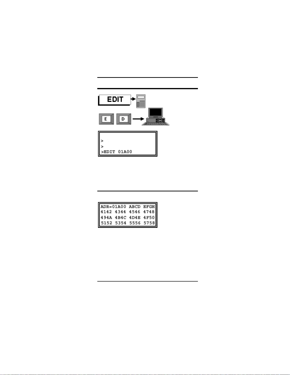
Remote Editing
The remote terminal screen has more columns
than the LCD and will look like this:
00000 42 43 44 45 46 47 48 49
The ADDRESS is followed by the DATA in
eight memory locations. As usual with terminal
editing the SPACE/BACKSPACE keys move
the cursor through the data. Hex keys 0-9 and
A-F will change the data. The ADDRESS can
be changed by backspacing into the address
field. When the ENTER key is pressed the
ASCII equivalent of the lines is shown at the
end and the next eight bytes presented for
editing:
00000 42 43 44 45 46 47 48 49 BCDEFGHI
00008 00 B1 46 92 8F FF 91 0C
Only ASCII characters 20H to 7EH are sent
through the interface, after the MSB has been
stripped. The others are sent as a point (full
stop), because control characters will be
interpreted by the terminal instead of being
printed.
To get out of the edit routine, press the
ESCape key.
EDIT KEY 61
Page 62

DUMP RAM
DATAMAN S4 MANUAL
DUMP (START),(BYTES)
Dump works only via terminal and is similar to
EDIT above. It dumps 8 bytes per line in HEX
with ASCII equivalents. Inputs required are
START address and number of bytes - up to
FFH or 255. If 0 bytes then the dump continues
until ESCape is pressed.
62 DUMP RAM
Page 63

DATAMAN S4 MANUAL
SEND KEY
SEND (START),(END)
Transmits the block from START to END
inclusive through the serial interface. The FILE
FORMAT and BAUD RATE are chosen in the
SETUP routine.
If handshaking is set to RTS or DTR then those
signals must be true before transmission
proceeds. Assuming that the transmission is
proceeding with regard to RTS, if RTS
becomes false the transmission stops until
RTS becomes true again.
At any point the transmission may be aborted
by the user pressing the keypad ESCape key.
SEND KEY 63
Page 64

RCVE KEY
DATAMAN S4 MANUAL
S4 receives files in INTEL, MOTOROLA,
TEKHEX, ASCII or BINARY format, as defined
in the SETUP routine. You are prompted for
START and END addresses in ASCII and
BINARY only, because these transmissions do
not contain any destination for the data. If the
transmission continues after the specified END
address, the remainder of the file is "run out"
i.e. received, but discarded.
The keypad ESCape key will abort
transmission whilst waiting for a file, or during
the reception of a file. After the ESCape key,
S4 waits for a second to make sure that no
more data will be sent - otherwise such data
would be misinterpreted as keyboard
instructions. Also the sending terminal might
lock-up if RTS is not held true until the End-OfFile is reached. If more data is sent then S4
stays in the routine - the user should stop the
file transmission from the sending end. Errorcheck failures built into the file-format are
64 RCVE KEY
Page 65

DATAMAN S4 MANUAL
reported e.g. Checksum errors are reported
together with the address at which the error
was detected, which is usually the end of the
row in which the error occurred. When a file is
received correctly S4 displays the last address
where code was stored.
Before returning to command mode, S4
waits until the data input has been inactive
for at least one second. This is to "run-out"
any extra data to avoiding hanging-up the
sending computer. When sending from a
batch-file, a delay of over one second must
be inserted before the next command, to
prevent S4 seeing it as "garbage".
RCVE KEY 65
Page 66

FUNC KEY
DATAMAN S4 MANUAL
The FUNC key acts like a SHIFT - it gives
access to an alternative set of keyboard
functions. There is no equivalent at the
terminal - all terminal functions have two
unique letters.
To indicate that an extra function is expected,
the prompt changes from a >> to a *.
66 FUNC KEY
Page 67

DATAMAN S4 MANUAL
FUNC LIB = Make Library
MAKE LIBRARY is the opposite to loading a
library. It makes a LIBRARY PROM from the
code and defaults present in the TPA area.
MAKELIB lets you make a LIBRARY ROM,
with your own preferences incorporated. The
code in the TPA area is moved into USER
RAM, from 8000 upwards, and certain framing
information (42 bytes – see LIBRARY) added.
All you have to do after MAKELIB is to
configure for a 27256, then program it with
USER RAM from 08000 TO 0FFFF.
Such a LIBRARY ROM will restore the PROM
ALGORITHM, BAUD-RATE, FILE-TYPE and
other system-variables which were set when
you made it.
If you lend your S4 to a colleague, it is wise
precaution to make a LIBRARY ROM with your
own configuration first. Then, when you get
you S4 back, you can restore all your own
preferences (if you do get it back).
FUNC LIB = Make Library 67
Page 68

DATAMAN S4 MANUAL
FUNC SETUP = Advanced
To adjust advanced SETUP parameters you
will need to convert numbers from decimal to
hexadecimal.
• Shutdown Time - 1E = 30 minutes
The audible tones that S4 makes can be
changed in pitch, or removed altogether by
setting to 00.
• High Tone 98 = 1520 hz
• Low Tone AC =1720 hz
• Busy Tone 50 =800 hz
68 FUNC SETUP = Advanced
Page 69

DATAMAN S4 MANUAL
The battery charger is prevented from working
if the battery is too cold or too hot i.e. not
between min and max. If you want to adjust
these levels, one degree centigrade is about
2.7 points.
• Max Batt Temp AA =42°C
• Min Batt Temp 64 = 15°C
The following parameters govern the operation
of the Fuel Gauge. Charge time and discharge
time are proportional to the number of seconds
needed to change battery contents by one
ma/hr. Smaller values will make the apparent
rate of charge or discharge faster. Values
should be adjusted on test if accuracy of the
Fuel Gauge is important.
• Charge time 07
• Discharge time 11
Deep and Normal Discharge govern the
automatic operation of the Battery Charger.
They are set to 25% and 75% on a cold start.
The rule is that if a charger is connected when
S4 is switched on, the battery will be charged if
the Fuel Gauge shows less than Norm
Discharge level.
When S4 is in operation with the charger
connected, the Fuel Gauge is allowed to fall to
the Deep Discharge level before the battery is
recharged.
• Deep Discharge 40
• Norm Discharge C0
FUNC SETUP = Advanced 69
Page 70

DATAMAN S4 MANUAL
FUNC INFO = Self Test
These tests used to verify the working of the
LCD, the keypad and the USER RAM. ENTER
will run the test. ESCape will pass on the next
test.
The LCD TEST fills the display with a character
sequence.
The KEYPAD TEST requires you to press all
the keys in sequence, left to right, top to
bottom. It cannot be completed until all the
keys have been pressed in turn.
The DESTRUCTIVE RAM TEST fills USER
RAM with a Pseudo-Random number
sequence, and then compares it with the same
sequence. The original contents are lost.
70 FUNC INFO = Self Test
Page 71
DATAMAN S4 MANUAL
FUNC BURN = Chip Erase
This command will Chip-Erase FLASH PROMs
and some EEPROMs.
Most EEPROMs and FLASH PROMs do not
need to be erased before programming – in
fact many do not support a Chip-Erase feature,
in which case S4 will display the following
message when this command is used:
>ERASE 2864
Sorry, impossible
Some FLASH PROMs, such as AMD/Intel 28
series FLASH and AMD 29 series MUST be
erased prior to programming – remember S4
doesn’t erase the device automatically, you
must use the Chip Erase command.
>ERASE
AMD 29F010
5V Erase
Press ENTER to erase the device, or ESC to
exit.
FUNC INFO = Chip Erase 71
Page 72

DATAMAN S4 MANUAL
FUNC SEEK = Seek Not Equal
This command is the converse of the SEEK
command. It finds locations which are not the
same as a specified byte. It can be useful in
finding PROM locations which failed to erase.
72 FUNC SEEK = Seek Not Equal to
Page 73

DATAMAN S4 MANUAL
FUNC FILL = Pseudo Random Fill
Fills the memory block with a Pseudo Random
Number sequence from START to END
inclusive.
Pseudo random numbers are generated by a
computer program. They are not true random
numbers - if they were they would always be
different and unpredictable. Pseudo random
numbers are predictable. They are always the
same sequence. For testing purposes, they are
random enough.
The algorithm is a 15-bit left-shift with the least
significant bit being the XOR of previous bits 0
and 14. This sequence repeats every 32,767
shifts. The lower 8 bits are used. Every byte
will look like a left shift of the preceding byte,
except for the LSB which is unpredictable.
FUNC FILL = Pseudo Random Fill 73
Page 74

DATAMAN S4 MANUAL
FUNC EDIT = Edit System Ram
System memory space can be seen and
altered using a FUNC version of EDIT. System
memory space is where the working program is
stored when loaded from a LIBRARY ROM, in
the Transient Program Area which extends
from 8000 to FFFF. If the FUNC key is pressed
from the command prompt, the prompt
changes from a >> to a *. EDIT then works on
system memory. The LCD behaves exactly as
the normal edit routine.
WARNING *EDIT allows changes to the
working program and system variables. S4
can be crashed by editing the running
program, if indiscriminate changes are
made to the stack or cod e. Regard the TPA
as a "NO GO" area unless you a re ce rtain of
what you are doing. You can recover from
any changes by press ing the RE SET bu tton
and reloading the LIBRARY ROM.
74 FUNC EDIT = Edit System Ram
Page 75

DATAMAN S4 MANUAL
FUNC EDIT = Edit System Ram 75
Page 76

DATAMAN S4 MANUAL
FUNC RCVE = Receive Library
Receives a new library ROM into the TPA area.
This command is useful if you download a new
library from our Bulletin Board to your
computer. When you have sent the file to S4
you can make a new LIBRARY ROM with
MAKELIB.
Your SETUP must be INTEL format for this
command to work.
When receiving a Library file in this manner,
code from F800-FFFF must be stripped out
from the Intel Hex file. Otherwise S4 will crash
when it receives the file. Intel Hex files can
easily be edited using an ASCII text editor.
After reception of a correct library file, S4 must
be RESET, and then Library should be started,
by pressing ENTER at the S TART LIBR ARY?
Prompt.
76 FUNC RCVE = Receive Library
Page 77

DATAMAN S4 MANUAL
FILE FORMAT
>FILE FORMAT
INTEL
Has no keypad equivalent. The space and
backspace keys will change the file format from
ASCII INTEL MOTOROLA TEKHEX BINARY.
Either ESCape or ENTER will leave the file
format set at the last choice shown on the
screen.
FILE FORMAT 77
Page 78

QUIET MODE
DATAMAN S4 MANUAL
Has no keypad equivalent.
QUIET MODE turns off the RS232 output.
There is no response on the computer screen
until the command is entered again.
This might be useful for batch file commands
which write directly to COM1 etc.
78 QUIET MODE
Page 79

DATAMAN S4 MANUAL
BAUD RATE
>SET SERIAL PORT
9600
Has no keypad equivalent.
Sets the baud rate, using the SPACE and
BACKSPACE keys to show the choices:
300 600 1200 2400 4800 9600 14400 28800
115200
ESCape or ENTER leaves the rate set at the
last value shown.
On exit, you are prompted to change the
terminal baud rate.
BAUD RATE 79
Page 80

EXECUTE
DATAMAN S4 MANUAL
>EXEC 01234
Starts program execution at the address
requested. This is mainly for programmers who
have written code for S4. The default
ADDRESS is the last one used in the EDIT
routine. You can set any value you please.
• 00000 gives a cold start
• 0F000 gives a warm start
80 EXECUTE
Page 81

DATAMAN S4 MANUAL
RS232 Serial Interface
The serial RS232 interface uses an IC made
by Motorola, part number MC145406, which
meets RS232 standards of voltage and current
on inputs and outputs.
Current can be sourced by the outputs into
any load on the RS232 interface, but it is
unlikely that such current w ill exceed 5ma.
Nevertheless this current comes from the
battery. Leaving th e RS232 lead connected
will reduce battery life by about 20%. When
S4 powers down, the RS 232 voltages fall to
zero.
RS232 Serial Interface 81
Page 82

DATAMAN S4 MANUAL
Baud Rates
The baud-rate of a transmission is the
reciprocal of the time used to send one bit.
Asynchronous serial transmissions as
commonly used by computers have extra bits
to frame and check the data: a START bit, then
the DATA bits, then an optional PARITY bit
and then one or more STOP bits. Baud-rate
indicates the fastest possible transmission
speed: it does not indicate the actual
transmission speed. You can send one byte
per fortnight at any baud-rate. When a
computer has reached its limiting speed for
processing the data, increasing the baud-rate
will not make it send or receive any faster – the
gaps between characters will just get bigger.
Some systems claim high baud rates but they
are slow at receiving data files all the same.
To prevent the sending device supplying data
faster than the receiving device can digest it,
the receiver prompts with a signal RTS
(Request-To-Send), and/or DSR (Data-SetReady). These signals are called handshaking.
Leads used for serial communications must
connect the handshaking signals properly, to
prevent data getting lost. As S4 can actually
receive data-files at 115200 baud with 1 stop
bit, the highest rate supported by a PC, without
stopping the transmission, which means that
there will be no problem even if RTS is not
connected.
S4 has two active handshake signals in each
direction. DTR is provided too and is always
true - it proves only that the cable is connected.
82 Baud Rates
Page 83

DATAMAN S4 MANUAL
The signal at the computer end which requests
data is usually RTS or DTR, and you can probe
these with a meter to find which one is at a
high level. If they are both high then it is likely
that DTR is wired at a positive level, and RTS
is the active stop/go signal.
It may be possible to manage without any
active handshaking, but some computers lockup if they do not see the correct signals. The
implementation is as follows: at switch-on, S4
looks for CTS. If CTS is present then S4 puts
out the introductory message to the serial
interface as well as putting it in the LCD.
Whether or not CTS was present at switch-on,
S4 polls both devices, the keypad/LCD and
serial channel for commands. When a
command is received then the responses go to
the requesting device.
Note: Both devices are only polled
simultaneously at the command prompt. If
S4 is in the middle of doing something
requested by the RS232, the keypad is
ignored, and vice versa. No other method
makes sense.
S4 receives commands through the serial
interface in an interactive way i.e. it expects
you to wait for the resulting output. You
normally expect computers programs to work
like that and when entering commands and
data by hand it causes no problem. However,
in the rare circumstance that you wish to send
S4 commands from a batch-file which does not
wait for results, you must make sure that S4's
Baud Rates 83
Page 84

DATAMAN S4 MANUAL
RTS signal handshakes with your computer to
prevent it sending commands faster than S4
can action them.
When sending files, remember that most
computers cannot process data as fast as S4
can. To be safe, send at a slow baud rate or
connect the RTS handshake line. You can
usually see a bad transmission if you inspect
the file after receipt - some of the lines will be
short and contain bad characters.
84 Baud Rates
Page 85

DATAMAN S4 MANUAL
INTEL Format.
An Intel format file can be examined w ith a
text editor and printed. Each record is a
single line of ASCII characters, expressing
bytes as Hexadecimal pairs, terminated
with Carriage return and Linefeed.(0D,0A
Extended Address Record.
Position Remarks
1 ":" ASCII Colon delimiter
2-3 "02" Byte count
4-7 "0000" Address not used
8-9 "02" Record type
10-13 Upper Segment Base Address.
Top 16 bits of 20 bit address
Most significant byte first. 2
bytes as 4 HEX characters.
USBA defaults to 0 if not sent.
14-15 Checksum complement of all
bytes except colon, linefeed
and return. 1 byte as 2 hex
characters. This makes the
line add up to zero.
16-17 Carriage return and line feed
Data Record.
Position Remarks
1 ":" ASCII Colon delimiter
2-3 Data byte count in HEX, max
"20" (32 bytes or 64 ASCII
characters)
4-7 Lower 16 bits of 20 bit address
Most significant byte first. 2
bytes or 4 HEX characters.
Intel Format 85
Page 86

DATAMAN S4 MANUAL
Must be added to USBA to
form 20 bit address.
8-9 "01" Data Record
10-N Data bytes in hexadecimal.
Each byte is two HEX
characters
N+1,2 Checksum complement of all
bytes except colon, linefeed
and return. This makes the line
add up to zero.
N+3,4 Carriage return and line feed
End of File Record.
Position Remarks
1 ":" ASCII Colon delimiter
2-3 "00" Number of Bytes.
4-7 2 byte Transfer Address
usually "0000"
8-9 "01" Record Type
10-11 Checksum complement of all
bytes except colon, linefeed
and return usually "FF" This
makes the line add up to zero.
12-13 Carriage return and line feed
86 Intel Format
Page 87

DATAMAN S4 MANUAL
MOTOROLA S Format
A Motorola, Exorciser or "S" Format file can be
examined using a text editor and printed. Each
record is a single line of ASCII characters,
expressing bytes as hexadecimal pairs,
terminated with Carriage return and Linefeed
(0D,0A). All records start with an "S". The
transmission is terminated by ASCII End-ofFile
S0 Header Record
Position Char acter
1-2 "S0"
3-N Comments
N+1,2 Carriage Return & Line Feed
S1 Data with 2 Byte Address
Position Char acter
1-2 "S1"
3-4 Record length = data bytes
plus 3 2 for address & 1 for
checksum.
5-8 2 byte address as 4 HEX
characters Most Significant
Byte first.
9-N Data bytes in hexadecimal,
each byte is two HEX
characters.
N+1,2 Negation of checksum of bytes
excluding "S1". Makes the line
add up to "FF".
N+3,4 Carriage Return & Line Feed.
Motorola S Format 87
Page 88

DATAMAN S4 MANUAL
S2 Data with 3 Byte Address
Position Char acter
1-2 "S2"
3-4 Record length. Number of data
bytes plus 4 (3 for address & 1
for checksum).
5-10 3 byte address as 6 HEX
characters Most Significant
Byte first.
11-N Data bytes in hexadecimal,
each byte is two HEX
characters.
N+1,2 Negation of checksum of bytes
excluding "S2". Makes the line
add up to "FF".
N+3,4 Carriage Return & Line Feed.
S3 Data with 4 Byte Address
Position Char acter
1-2 "S3"
3-4 Record length = data bytes
plus 5 (4 for address & 1 for
checksum).
5-12 4 byte address as 8 HEX
characters Most Significant
Byte first.
13-N Data bytes in hexadecimal,
each byte is two HEX
characters.
N+1,2 Negation of checksum of bytes
excluding "S3". Makes the line
add up to "FF".
N+3,4 Carriage Return & Line Feed.
88 Motorola S Format
Page 89

DATAMAN S4 MANUAL
S7 End of File Record
Position Char acter
1-2 "S7"
3-4 "05" Record length.
5-10 4 byte start address usually
"00000000"
11-12 Negation of checksum of bytes
excluding "S7". Makes the line
add up to "FF".
13-14 Carriage Return & Line Feed.
S8 End of File Record
Position Char acter
1-2 "S8"
3-4 "04" Record length.
5-10 3 byte start address usually
"000000"
11-12 Negation of checksum of bytes
excluding "S8". Makes the line
add up to "FF".
13-14 Carriage Return & Line Feed.
S9 End of File Record
Position Char acter
1-2 "S9"
3-4 "03" Record length.
5-10 2 byte start address.
11-12 Negation of checksum of bytes
excluding "S9". Makes the line
add up to "FF"
13-14 Carriage Return & Line Feed
Motorola S Format 89
Page 90

DATAMAN S4 MANUAL
Tektronix Format
A Tektronix format file can be examined using
a text editor and printed.
Each record is a single line of ASCII characters,
expressing bytes as hexadecimal pairs,
terminated with Carriage return and Linefeed
(0D,0A).
The transmission is terminated by ASCII Endof-File (1A).
Tek Standard Data Record.
Position Char acter
1 "/" Slash character
2-5 Four HEX characters show
two byte Load Address, most
significant byte first.
6-7 Two HEX characters show
Byte Count (how many Data
Bytes not including checksums,
% or address)
8-9 Two HEX characters show
checksum of HEX characters
in Load Address and Byte
Count.
10-N Data Bytes, each byte is two
HEX characters.
N+1,2 Two HEX characters show
checksum of HEX characters
in Data Bytes
N +3,4 Carriage Return & Line Feed.
Tek End of File Record.
Position Char acter
1 "/" Slash character
90 Tektronix Format
Page 91

DATAMAN S4 MANUAL
2-5 Four HEX characters show
two byte Start Address, most
significant byte first.
6-7 "00" Byte count.
9-10 Two HEX characters show
checksum of all previous HEX
characters, not including "/",
11-12 Carriage Return & Line Feed.
Tek Extended Data Record.
Position Char acter
1 "%" Percentage character
2-3 Two HEX characters
expressing character count in
record, not including "%"
4 "6" for data record
5-6 Checksum of all HEX
characters not including "%".
7-N Between 2 and 17 characters.
The first HEX character
specifies how many HEX
characters follow showing
Load Address, most significant
byte first.
N-M Data bytes, each byte is two
HEX characters.
M+1,2 Carriage Return & Line Feed.
Tek Extended End of File Record.
Position Char acter
1 "%" Percentage character
2-3 Two HEX characters
expressing character count in
record, not including "%".
4 "8" for EOF record
Tektronix Format 91
Page 92

DATAMAN S4 MANUAL
5-6 Two HEX characters
expressing checksum of all
HEX characters except "%".
7-N Between 2 and 17 HEX
characters. The first HEX
character specifies how many
HEX characters follow
showing Start Address, most
significant byte first.
N+1,2 Carriage Return & Line Feed.
92 Tektronix Format
Page 93

DATAMAN S4 MANUAL
ASCII Formats
Each data byte is translated into two
hexadecimal ASCII characters, sent Most
Significant Nybble first. ASCII is similar to
INTEL, MOTOROLA and TEKHEX, except that
nothing but the raw data is sent - no addresses,
no checksums. After 32 bytes or 64 characters
a LINEFEED and CARRIAGE RETURN are
sent (0D 0A), which enables the transmission
to be received by a serial printer or a terminal.
At the end of the transmission an End-of-File
character (1A) is sent.
ASCII is normally sent and received as an 8 bit
transmission. The MSB is masked low when
receiving, placed low when sending.
When receiving, S4 asks for START and END
addresses where the block will be stored.
NOTE: INTEL, MOTOROLA and TEKHEX
transmissions can be inspected by
receiving them in ASCII format. Then you
can see delimiters, addresses and
checksums.
An ASCII End-of-File
Hen receiving character is not sent when the
format is set to BINARY because it would be
received as data. Sending BINARY files from
S4 is possible, but may be difficult to
implement at the receiving end. The computer
must expect a pre-defined size of block and
know where to put it. When receiving a block in
BINARY format, S4 has no way of knowing
when the computer has finished sending. You
ASCII Format 93
Page 94

DATAMAN S4 MANUAL
must press ESCape when the transmission is
ended.
NOTE Computers will not send a BINARY
file through their serial interface, using PIP
or COPY routines, unless you add a suffix:
COPY needs /B, PIP needs [O]. Otherwise
the transmission is ab orted if an end-of -file
(1A) character is seen.
BINARY reception is useful to check other file
formats: every character that is sent appears in
S4's RAM, so you can see what is really being
received, including carriage returns, line feeds
etc.
94 ASCII Format
Page 95

DATAMAN S4 MANUAL
BINARY Format
The file is sent as a succession of bytes. The
data is not processed at all. S4 asks for
START and END addresses when receiving.
An ASCII End-of-File character is not sent
when the format is set to BINARY because it
would be received as data. Sending BINARY
files from S4 is possible, but may be difficult to
implement at the receiving end. The computer
must expect a pre-defined size of block and
know where to put it. When receiving a block in
BINARY format, S4 has no way of knowing
when the computer has finished sending. You
must press ESCape when the transmission is
ended.
NOTE: Computers will not send a BINARY
file through their serial interface, using PIP
or COPY routines, unless you add a suffix :
COPY needs /8, PIP needs [O1. Otherwise
the trans- mission is aborted if an end-offile (1A) character is seen.
BINARY reception is useful to check other file
formats: every character that is sent appears in
S4's RAM, so you can see what is really being
received, including carriage returns, line feeds
etc.
Binary Format 95
 Loading...