

Page 1

DATAMAN 530 series
Arbitrary Waveform Generator
User’s Guide
Version 1.03
Copyright © 2004-2010 Dataman Programmers Ltd
Page 2

DATAMAN 530 series AWG User’s Guide
For further information please contact us via phone or preferably e-mail at the
following address:
Address:
Dataman Programmers Ltd
Station Road
Maiden Newton
Dorset
DT2 0AE
United Kingdom
Phone:
Sales/General information: +44 (0) 1300 320719
Technical support: +44 (0) 1300 322903
Fax:
All Enquiries: +44 (0) 1300 321012
Internet:
URL: http://www.dataman.com/
e-mail: support@dataman.com - technical support
sales@dataman.com - sales
info@dataman.com - other information
- 2 -
Page 3

DATAMAN 530 series AWG User’s Guide
Contents
Package contents............................................................................................................6
Warranty conditions.......................................................................................................6
Software License Agreement.........................................................................................6
Precautions.....................................................................................................................7
1. Installation..................................................................................................................8
1.1. Requirements ......................................................................................................8
1.2. Hardware installation..........................................................................................8
1.3 Software installation ............................................................................................8
2. Hardware....................................................................................................................9
2.1. Hardware description..........................................................................................9
3. Basic information.....................................................................................................11
3.1. Layout of the front and rear panel.....................................................................11
3.2. Vocabulary........................................................................................................12
4. Main window...........................................................................................................13
4.1. Controlling settings of the outputs....................................................................13
4.1.1 Setting the output voltage...........................................................................14
4.1.2. Displaying the output level........................................................................15
4.1.3. Setting the output voltage shift..................................................................15
4.1.4. Load setting................................................................................................16
4.1.5. Setting the output attenuator of “L” output................................................16
4.1.6. Switching off the outputs...........................................................................16
4.1.7. Filter cut-off frequency setting ..................................................................17
4.2. Setting frequency..............................................................................................17
4.2.1. Setting waveform (standard format) frequency.........................................17
4.2.2. Setting waveform (arbitrary format) frequency.........................................18
4.3. Triggering controls............................................................................................19
4.3.1. “Single” mode............................................................................................19
4.3.2. “Period” mode............................................................................................20
4.4. Waveform screen..............................................................................................20
4.5. Main menu........................................................................................................23
4.6. Options window................................................................................................23
5. Waveform editors.....................................................................................................25
5.1 Standard waveform editor..................................................................................25
5.2. The Math editor.................................................................................................25
5.3. Freeform editor .................................................................................................31
5.4. Import from ASCII ...........................................................................................33
6. Performance characteristics.....................................................................................35
6.1. Outputs..............................................................................................................35
6.2. Waveform generation........................................................................................35
6.3. Synchro.............................................................................................................36
6.4. Power ................................................................................................................36
6.5. Mechanical characteristics................................................................................36
- 3 -
Page 4

DATAMAN 530 series AWG User’s Guide
List of figures and tables
Fig. 2.1.1. – Block diagram of the generator.................................................................9
Fig. 3.1.1. – Front panel...............................................................................................11
Fig. 3.1.2. – Back panel ...............................................................................................11
Fig. 4.1. – The main window.......................................................................................13
Fig. 4.1.1. – Outputs settings .......................................................................................14
Fig. 4.1.3.1. – The shift edit boxes...............................................................................15
Fig. 4.1.4.1. Setting the load........................................................................................16
Fig. 4.1.5.1. – Output attenuator controls....................................................................16
Fig. 4.1.6.1. – Controlling the activity of the outputs..................................................16
Fig. 4.1.7.1. – Filter setting controls............................................................................17
Fig. 4.2.1.1 – Setting frequency of “Standard” waveform...........................................17
Fig. 4.2.1.2. – Frequency edit boxes............................................................................17
Fig. 4.2.1.3. – Displayed frequency range controls.....................................................18
Fig. 4.2.2.1. – Setting frequency of “Arbitrary” waveform.........................................18
Fig. 4.2.2.2. – Frequency edit boxes............................................................................18
Fig. 4.2.2.3. – Displayed frequency range controls.....................................................19
Fig. 4.3.1. – Triggering controls..................................................................................19
Fig. 4.3.2. – Mode setting controls ..............................................................................19
Fig. 4.3.1.1. – Manual trigger event selection .............................................................19
Fig. 4.3.1.2. – External trigger event selection............................................................20
Fig. 4.3.2.1. – Period mode controls............................................................................20
Fig. 4.3.2.2. – Arm mode controls...............................................................................20
Fig. 4.4.1. – The waveform screen...............................................................................21
Fig. 4.4.2. – Waveform properties window.................................................................21
Fig. 4.4.3. – Waveform pop-up menu..........................................................................21
Fig. 4.4.4. – New waveform window...........................................................................22
Fig. 4.4.5. – List of editors...........................................................................................22
Fig. 4.4.6. – New waveform pop-up menu..................................................................22
Fig. 4.4.7. – Waveform creation editors ......................................................................23
Fig. 4.6.1. – The “Options” window............................................................................23
Fig. 5.1.1 .- The standard waveform editor screen ......................................................25
Fig. 5.2.1. – Math editor mode selection .....................................................................26
Table 5.2.2. – List of functions....................................................................................26
Fig. 5.2.3. – x range setting..........................................................................................26
Fig. 5.2.4. – Output waveform calculated with “Normalization” option on................27
Fig. 5.2.5. Defining waveform with “Normalize” option off ......................................28
Fig. 5.2.6. – Manipulating with sections......................................................................28
Fig. 5.2.7. – Parameters of the section in advanced mode...........................................28
Fig. 5.2.8. – Defining part of the waveform ................................................................29
Fig. 5.2.9. - Waveform assembled from three parts.....................................................30
Fig. 5.2.10. – Using “Y” and “Z” constants.................................................................31
Fig. 5.3.1. – The freeform editor main screen .............................................................31
Fig. 5.3.2. – Horizontal waveform position controls...................................................32
Fig. 5.3.3. – Direction of drawing................................................................................32
Fig. 5.3.4. – Curve mode controls................................................................................32
Fig. 5.3.5. – Smoothness setting..................................................................................33
Fig. 5.4.1. – Import from ASCII file............................................................................33
- 4 -
Page 5

DATAMAN 530 series AWG User’s Guide
Fig. 5.4.2. – Import settings.........................................................................................34
Fig. 5.4.3. – Postprocessing settings............................................................................34
Table 6.1.1. – Outputs..................................................................................................35
Table 6.2.1. – Waveform generation ...........................................................................36
Table 6.3.1. – Synchro.................................................................................................36
Table 6.4.1. – Power....................................................................................................36
Table 6.5.1. – Mechanical characteristics....................................................................36
- 5 -
Page 6

DATAMAN 530 series AWG User’s Guide
Package contents
- DATAMAN 530 series generator – 1pc
- USB cable – 1pc
- Plug in adapter – 1pc
- installation leaflet – 1pc
- CD with software and user’s guide in pdf – 1pc
Warranty conditions
Dataman Programmers Ltd guarantees reliable operation of the generator in
compliance with this documentation during a period of 24 months (2 years) from the
date of purchase.
Should a malfunction occur during the warranty period, excluding errors for which
Dataman can not be held responsible, Dataman guarantees the repair of the product or
its replacement with a new or repaired one free of charge.
Dataman shall not be responsible for malfunctions of the device caused by an
accident, incorrect usage, unauthorized interventions or similar.
When requesting the warranty service, the customer should send the device in its
original packaging to Dataman with a description of the defect or malfunction. The
customer agrees that when returning a product it would be insured against damage or
loss during transport.
Software License Agreement
This legal document is an agreement between you, the end user, and Dataman
Programmers Ltd. By installing this product on your computer, you are agreeing to
become bound by the terms of this agreement and warranty conditions.
1. GRANT OF LICENSE. Dataman Programmers Ltd as Licensor, grants you, the
Licensee, a nonexclusive right to use and display this copy of the 530 software
(hereinafter the "SOFTWARE"), device and accompanying written materials, on a
single COMPUTER at a single location and only together so long as you comply with
the terms of this License.
2. OWNERSHIP. As the LICENSEE, you own the magnetic or other physical media
on which the SOFTWARE is originally or subsequently recorded or fixed, but an
express condition of this License is that Dataman Programmers Ltd retains title and
ownership of the SOFTWARE recorded on the original disk copy(ies) and all
subsequent copies of the software, regardless of the form or media in or on which the
original and other copies may exist. This License is not a sale of the original
SOFTWARE or any copy.
3. COPY RESTRICTIONS. This SOFTWARE, device and accompanying written
materials are copyrighted. Unauthorized copying or copy attempt of the device,
including module which has been modified or included with any other system, or of
- 6 -
Page 7

DATAMAN 530 series AWG User’s Guide
written materials is expressly forbidden. It is, however, allowed to pass SOFTWARE
on as the DEMO version. You may be held legally responsible for any copyright
infringement which is caused or encouraged by your failure to abide by the terms of
this License.
4. DISCLAIMER OF THE WARRANTY OF ANY KIND CONCERNING
SOFTWARE. This SOFTWARE and accompanying written materials are provided
"AS IS" without a warranty of any kind. Further, Dataman Programmers Ltd does not
warrant, guarantee or make any representations regarding the use, or the results of
use, of the SOFTWARE, device or written materials in terms of correctness, accuracy,
reliability, currentness, or otherwise. The entire risk as to the results and performance
of the software is assumed by you.
Precautions
Please observe following recommendations to avoid possible problems that might
occur while using the generator.
- read the User’s Guide
- always connect the device using a cable included in a package. If it is not possible,
always use USB 2.0 cable.
- do not connect any voltage source to the outputs.
- never connect any voltage out of -10V to +13V range to the external trigger (Si)
input (frequencies of up to 20 kHz). For frequencies higher then 20 kHz the voltage
range of –0.5 to +4V is recommended.
- never connect any voltage to the generator ground. It may result in the device, or
computer damage.
- use only the supplied wall adapter. If it is not possible, you can use any DC voltage
source in range of 10 to 18V able to supply at least 300mA. The connector’s polarity
is not important. Please be sure that no of the power supply poles are directly
connected to the ground of the device. The power supply should be fuse protected
against of overloading.
- do not open or dismantle the case, it will void any warranty. There no user
serviceable parts inside.
- 7 -
Page 8

DATAMAN 530 series AWG User’s Guide
1. Installation
1.1. Requirements
Minimum configuration:
- PC PENTIUM compatible computer
- 64MB RAM
- CD-ROM
- VGA with resolution 800 x 600
- USB port 1.1
- mouse or other tracking device
- at least 20MB free space on the hard drive
- MS Windows 98 SE, ME, 2000 or XP
Recommended configuration:
- PC PENTIUM compatible computer with speed of at least 800MHz
- 256MB RAM
- CD-ROM
- VGA with resolution at least 1024x768
- USB port 2.0
- mouse or other tracking device
- at least 20MB free space on the hard drive
- MS Windows 98 SE, 2000 or XP
1.2. Hardware installation
Connect one side of the cable to the computer and the other one to the device. Proceed
with the software installation.
WARNING: Always use the cable included in the package. Using the improper
cable can cause communication problems with the computer.
1.3 Software installation
The software and the device drivers are located on the enclosed CD. Insert the CD
into the CD-ROM drive. Then follow the instructions of the setup program that should
launch automatically. If the CD autorun is not enabled in your computer’s settings,
please run file autorun.exe from the CD.
- 8 -
Page 9
DATAMAN 530 series AWG User’s Guide
2. Hardware
The information contained in this chapter will help you understand features of your
device.
2.1. Hardware description
The 530 series arbitrary waveform generator connects to computer via USB 2.0. The
device accuracy is assured by the stability of the circuits and by the calibration
constants stored directly in the device.
The output waveform of can defined by a maximum of 16384 samples with 12 bits
resolution. The generator is equipped with two outputs. The output range of low level
output (L) is +– 4.5V with an output resistance of 50 Ohm. It is calibrated for up to 10
MHz. The high level output (H) offers +- 25V voltage range, with 600 Ohm
resistance. It is calibrated for up to 200kHz.
HON
H
L
SO
SI
DN/
QF(15:0)
HA PH
LA
PLL2
HD
VS(11:0)
FL(3:0)
SW
SQ
AF
DL(1:0)
DSC
CLDPLL1RF(15:0)
CX(6:0)
DAC
VA(11:0)
AK(12:0)
AS(12:0)
CNT
AC
MD(11:0)
M
WAC
RCD
WA(13:0)
clk
RCN
RA(13:0)
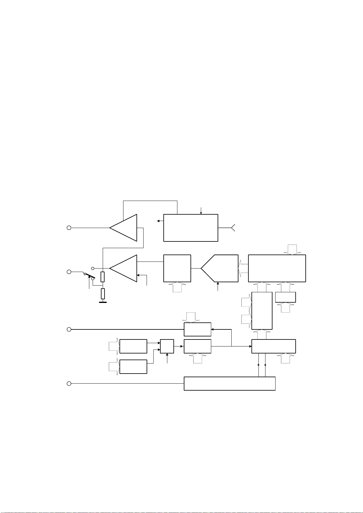
Fig. 2.1.1. – Block diagram of the generator
The block diagram of the generator is on the picture 2.1.1. The output amplifier LA is
connected to attenuator with settable attenuation of 0 or 20dB. The output of this
attenuator is connected to the output connector. The LA output amplifier together with
HA output amplifier are controlled by the output of the fast DA converter (DAC) via
low pass filter with settable cut-off frequency (AF). The samples of the output
waveform are stored in local storage (M) of the generator. The sample handling is
provided by (CNT, DSC, CLD, RCN, RCD, WAC) modules. They are clocked by
- 9 -
Page 10

DATAMAN 530 series AWG User’s Guide
PLL controlled generators to ensure smooth tuning throughout the whole frequency
range.
The generator works in one of following operation modes:
- PERIODIC - The output waveform is generated periodically with no
possibility of external synchronization. The output synchronization pulse is
issued at the beginning of each output period through the synchronization
output (SO).
- TRIGGERED – The waveform generation is started by the input
synchronization pulse from the SI connector.
- MANUAL – The waveform generation is user-triggered through the button
click.
The device is powered mainly from the USB interface. However, when using the high
level output, it is necessary to connect the supplied wall socket adapter. The PH
module works as the high level output power supply.
- 10 -
Page 11
DATAMAN 530 series AWG User’s Guide
3. Basic information
3.1. Layout of the front and rear panel
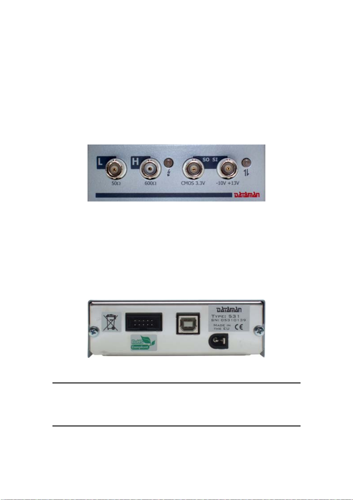
There are four connectors and two LEDs on the front panel. The BNC connectors
represent the low and high level outputs (L and H) and the input and output
synchronization signals (SI, SO). The LEDs are located on the left and the right side
of the front panel. The meaning of the left side LED is as follows:
- Green color – the high level output is powered
- Orange color – the thermal shut down condition of high level amplifier is met.
Fig. 3.1.1. – Front panel
The right side LED indicates the state of the device and its communication activity.
The different colors have following meanings:
- Red color – the device is powered, but not configured.
- Green color – the device is powered and properly configured
- Orange Color - the communication is in progress.
On the rear panel there are three connectors. The center one is the USB interface
connector, the right one is the external power adapter input and the third 10 pin
connector is an auxiliary connector reserved for future use.
Fig. 3.1.2. – Back panel
WARNING: Use only the supplied wall socket adapter. If it is not possible you
can use any DC power supply with output voltage from 10 to 18 V and at least
300mA of output current. The polarity of connector is not important. Please
assure, that no pole of power supply is connected directly to the ground of the
instrument (via measuring cable ground for example).
`
- 11 -
Page 12

DATAMAN 530 series AWG User’s Guide
3.2. Vocabulary
This chapter explains the technical vocabulary used throughout the text.
Click – Position the mouse cursor over the chosen object. Then press and release the
left mouse button.
Double-Click – Two fast successive clicks.
Drag – Move the mouse cursor over the object you want to drag. Press the left mouse
button and hold it down. Now you can drag the chosen object when moving the
mouse cursor. After releasing the mouse button the object moves to the new location.
Enter the value into the edit box – Click the edit box. Use the keyboard to enter the
desired value and confirm it by pressing the “Enter” key on the keyboard.
Insert the value into the edit box – Click the edit box. Use the keyboard to enter the
desired value.
Set the value using the scroll bar – It is possible to change a value simply by
dragging the scroll bar slider. Clicking the arrows of the scroll bar increases or
decreases the value by smallest steps. Clicking in between the slider and the arrows
changes the value by larger steps.
Select the value from the combo box – Open the list of all possible values of the
combo box by clicking it. Then set the desired value by clicking it.
- 12 -
Page 13

DATAMAN 530 series AWG User’s Guide
4. Main window
After starting the application the main window appears. It contains all the controls for
the generator.
Fig. 4.1. – The main window
4.1. Controlling settings of the outputs
Elements for controlling the settings of the outputs are located on the left side of the
main window.
- 13 -
Page 14

DATAMAN 530 series AWG User’s Guide
Fig. 4.1.1. – Outputs settings
Using these elements it is possible to control amplitude and DC shift of the output
waveform. It is also possible to display the proper amplitude depending on the
connected load and set the low pass filter cut-off frequency.
4.1.1 Setting the output voltage
The output voltage can be adjusted by dragging the vertical scroll bar labeled “Lvl”.
The output level can be set also relatively to the reference value, which is displayed in
the edit box labeled “dB”. The reference value can be set in following two modes:
- Auto dB - the reference value is continuously adjusted to the output level.
Please note that the “dB” edit box always displays 0 in this mode.
- Man dB - the edit box (“dB”) shows the relation of output level value to the
reference value. Clicking the “Set 0 dB” button sets the reference value to the current
output level.
It is possible to set the output level in following manner:
- Enter the value into the “dB” edit box
- Enter the value into the “Vpp” or “Vp” edit boxes.
- 14 -
Page 15

DATAMAN 530 series AWG User’s Guide
TIP: When the value entered to the edit box is out of range, the device sets the
closest possible one.
WARNING: When the output voltage is outside of recommended range, the
“Lvl” label turns red. In this case, the value of output voltage may not meet the
performance characteristics of the device.
4.1.2. Displaying the output level
The edit boxes display following information:
- Vpp – Peak to peak voltage
- Vp - Minimum or maximum output voltage of the waveform (using the “+” or “-“
buttons)
- Vrms - Root Mean Square value
- Vavg – Average value
- dBW, dBmW – Relation of power on the connected load with respect to 1W or
1mW
- dBmV, dBuV – Relation of the Vrms of output voltage with respect to 1mVrms or
1uVrms
WARNING: The value of Vp depends on the output shift. When the “Vrms from
AC” option is turned off, the Vrms and Vavg value depend on shift as well.
Clicking the button switches the “Vpp”, “Vp”, “Vrms”, or “Vavg” edit boxes on or
off. The “Vp” edit box can display the maximum or minimum value of the waveform
depending on which button of “+” or “-“ has been selected.
4.1.3. Setting the output voltage shift
The output voltage shift is adjustable by dragging the “Shift” scroll bar. Generally, the
output voltage shift can be adjusted in following two modes:
- “Con” mode - the new shift voltage is updated in the device immediately.
- “Step” mode - the new shift voltage value is displayed in the additional (red)
edit box. Clicking the “OUT” button updates the shift voltage in the device.
You can also enter precise value to the additional (red) edit box. The value set in
device is displayed in the main (green) edit box.
Fig. 4.1.3.1. – The shift edit boxes
Clicking the “0” button sets shift in the device to the 0V. If the “Step” mode is on,
click “OUT” button to restore original shift voltage.
- 15 -
Page 16

DATAMAN 530 series AWG User’s Guide
WARNING: When the peak voltage of the generated waveform is out of
recommended range, “Shift” label turns red. In this case, the generated
waveform may not meet the performance characteristics of the device.
4.1.4. Load setting
The output voltage of the generator depends on the connected load. In order to ensure
the displaying of the correct voltage values, a real load value has to be provided. For
providing the real load value there are two buttons and a “Load” edit box. The edit
box always shows the last entered load. There are following ways to adjust the load
you can:
- Click on the “Open” button - no load is assumed on the output.
- Click on the “50” (“600”) button - a load equal to the output impedance is set.
Fig. 4.1.4.1. Setting the load
- Enter the load directly into the edit box.
WARNING: Connecting a load lower than 10 Ohm can result in the distortion of
output waveform.
4.1.5. Setting the output attenuator of “L” output
The output attenuator can be set to 0 or -20 dB. It is controlled by following two
buttons:
- button “0” sets the attenuation to 0 dB (1:1).
- button “-20” sets the attenuation to -20dB (1:10).
The “output voltage” edit boxes always display the actual output voltage.
Fig. 4.1.5.1. – Output attenuator controls
4.1.6. Switching off the outputs
The “On” and “Off” labeled buttons located in the “Output” box activate or deactivate
the outputs. Clicking the “Off” button deactivates outputs by setting voltage to 0V.
Clicking the “ON” button reactivates the outputs.
Fig. 4.1.6.1. – Controlling the activity of the outputs
- 16 -
Page 17

DATAMAN 530 series AWG User’s Guide
4.1.7. Filter cut-off frequency setting
A low pass filter can only be connected to both outputs simultaneously. The filter can
be switched on with cut-off frequency of 20 or 40 MHz.
Fig. 4.1.7.1. – Filter setting controls
4.2. Setting frequency
The output waveform can be defined in one of the following formats:
- standard format – the waveform is arbitrary, length is fixed to 8192 samples
- arbitrary format – both waveform and its length are arbitrary
4.2.1. Setting waveform (standard format) frequency
The term “frequency” indicates (for standard format) the frequency of the whole
waveform. For example, if the waveform is defined as two periods of the harmonic
signal, the frequency on the generator’s output is the double of the selected frequency.
The frequency on the output will meet the selected frequency only if the waveform
contains one period of the signal. The standard format is distinguished by the
“Waveform frequency” text in the top-left of the panel.
Fig. 4.2.1.1 – Setting frequency of “Standard” waveform
- The frequency can be set in following two modes:
- Con mode – all changes are updated in both the main (green) and additional
(red) edit box and are immediately set to device
- Step mode – all changes are updated only in additional (red) edit box. Main
edit box (green) displays the value set in the device. Clicking the “set” button updates
the value in the device.
Fig. 4.2.1.2. – Frequency edit boxes
A frequency can be adjusted by dragging the red rider to a desired value. The value
set in device is displayed by the green rider (red and green rider can differ only in
“step” mode).
- 17 -
Page 18

DATAMAN 530 series AWG User’s Guide
A scrollbar can be used for fine-tuning the frequency.
The frequency can be precisely specified also by entering a value into the additional
(red) edit box.
TIP: The frequency is being entered in Hz units. If, however, the letter “M”
follows the numeric value, the value is considered to be in MHz. If the letter “k”
follows numeric value, it is considered to be a kHz value.
Clicking “Zoom in” button decreases displayed frequency range, clicking “Zoom out”
increases displayed frequency range and clicking “Zoom away” sets displayed
frequency range to maximum.
Fig. 4.2.1.3. – Displayed frequency range controls
4.2.2. Setting waveform (arbitrary format) frequency
The term “Frequency” indicates (for arbitrary format) the sampling rate. The arbitrary
format is distinguished by the “Sampling rate” text in the top-left of the panel.
Fig. 4.2.2.1. – Setting frequency of “Arbitrary” waveform
- The frequency can be set in following two modes:
- Con mode – all changes are updated in both the main (green) and additional
(red) edit box and are immediately set to device
- Step mode – all changes are updated only in additional (red) edit box. Main
edit box (green) displays the value set in the device. Clicking the “set” button updates
the value in the device.
Fig. 4.2.2.2. – Frequency edit boxes
A frequency can be adjusted by dragging the red rider to a desired value. The value
set in device is displayed by the green rider (red and green rider can differ only in
“step” mode).
A scrollbar can be used for fine-tuning the frequency.
- 18 -
Page 19

DATAMAN 530 series AWG User’s Guide
The frequency can be precisely specified also by entering a value into the additional
(red) edit box.
TIP: The frequency is being entered in Hz units. If, however, the letter “M”
follows the numeric value, the value is considered to be in MHz. If the letter “k”
follows numeric value, it is considered to be a kHz value.
Clicking “Zoom in” button decreases displayed frequency range, clicking “Zoom out”
increases displayed frequency range and clicking “Zoom away” sets displayed
frequency range to maximum.
Fig. 4.2.2.3. – Displayed frequency range controls
4.3. Triggering controls
The waveform generation is controlled by trigger controls located in the middle right
of the main window.
Fig. 4.3.1. – Triggering controls
Waveform can be generated in following two modes:
- Single – the waveform is generated once on synchronization event
- Period – the waveform is generated continuously (the synchronization event has no
influence on generation)
Fig. 4.3.2. – Mode setting controls
4.3.1. “Single” mode
Following two trigger events can be selected in this mode:
- Manual trigger event – clicking the “Go” button starts the generation. Turn trigger
off (click “Off” button in the trigger panel) to select this mode.
Fig. 4.3.1.1. – Manual trigger event selection
- 19 -
Page 20

DATAMAN 530 series AWG User’s Guide
- External trigger event – rising or trailing edge on the “Si” input starts the generation.
Turn trigger on (click “On” button in trigger panel) to select this mode. Click
button to select leading edge or to select trailing edge.
Fig. 4.3.1.2. – External trigger event selection
4.3.2. “Period” mode
The waveform is continuously generated in this mode. Click “Go” button to enable
generation, click “Stop” button to stop it. Please note, that when the generation is
restarted (clicking “Stop” and “Go” button), the generation starts from the waveform
beginning.
Fig. 4.3.2.1. – Period mode controls
The “Si” input can be used as “ARM” input. Click “On” button on the ARM panel to
turn arm mode on. The generation is suspended if the stop value is detected on the
“Si” input. Click on “0” or “1” button of the “Stop level” panel to select stop value.
Fig. 4.3.2.2. – Arm mode controls
4.4. Waveform screen
The shape of the actual waveform and the list of an available waveforms are displayed
on the waveform screen. Drag the waveform from the list to the actual waveform
screen to select it. Please note, that the waveform format (“standard” or “arbitrary”)
influences also frequency controls. The “standard” waveforms are displayed in the
green color, “arbitrary” waveforms are displayed in yellow.
- 20 -
Page 21

DATAMAN 530 series AWG User’s Guide
Fig. 4.4.1. – The waveform screen
Waveforms can be modified using editors.
Double-clicking the waveform displays its properties.
Fig. 4.4.2. – Waveform properties window
Right-clicking the waveform in the list, displays the pop-up menu, where you can
select the operations with the waveform.
Fig. 4.4.3. – Waveform pop-up menu
- 21 -
Page 22

DATAMAN 530 series AWG User’s Guide
Click “Delete” to remove the waveform from the list.
Clicking “Properties” displays waveform properties (this operation is same as doubleclick on the item).
Click “Duplicate” to create the copy of the selected waveform. The copy will be
added to the end of the list.
Click “New” to open the “new wave” window, where you can select the parameters of
the new waveform. You can select waveform name, size and mode in this window.
Depending on the selected mode, the size can be selected from following range:
- Standard mode – the size is fixed to 8k
- Arbitrary mode – the size can be selected from 1 sample to 16k samples
Click “OK” button to create the waveform with specified parameters. The shape of
the new waveform is always the 0V constant.
Fig. 4.4.4. – New waveform window
The “Edit by” item of the pop-up menu contains the list of editors. Clicking the item
from the list starts selected editor. Please see chapter 5. for the information about
editors.
Fig. 4.4.5. – List of editors
Right-clicking the free space in the waveform list opens the pop-up menu, where you
can create new waveform.
Fig. 4.4.6. – New waveform pop-up menu
Click “New” to open the “new wave” window. This window was described in
previous text.
The “Create by” item contains the list of editors capable of creating the waveform.
Clicking the item from the list starts selected editor. Please see chapter 5. for the
information about editors.
- 22 -
Page 23

DATAMAN 530 series AWG User’s Guide
Fig. 4.4.7. – Waveform creation editors
The waveform list can be filtered by selecting filtering criteria below the list .
4.5. Main menu
The main menu consists of the following items:
Files | Exit – Exits from the application leaving the device running, but
switching off the high level output.
Files | Exit (preserve H output) - Exits from application leaving the both
device and high level output running
Settings | Process license file – Loads and processes specified license file
Settings | Options – Opens the “options” window (see chapter 4.5.1. for further
details).
Help | About – Opens the “about” window.
4.6. Options window
Clicking the proper item in the main menu opens the options window.
Fig. 4.6.1. – The “Options” window
- 23 -
Page 24

DATAMAN 530 series AWG User’s Guide
Following options are available:
Device | Automatically set output filters – indicates, whether the output filter
should be automatically selected to generate all major harmonics correctly and smooth
output waveform
Display | Vrms from AC – indicates, whether the effective and average value
of the signal will be influenced by vertical shift.
- 24 -
Page 25

DATAMAN 530 series AWG User’s Guide
5. Waveform editors
Following editors are available for waveform creation and/or modification:
- Standard waveform editor
- Math editor
- Freeform editor
- Import from ASCII file
Please see chapter 4.4 for instructions how to activate them.
5.1 Standard waveform editor
This editor can create “sine”, “saw”, “triangle”, “square”, “noise” signals.
Fig. 5.1.1 .- The standard waveform editor screen
The “Duty cycle” parameter can be specified for triangle and square. Enter the
number from 0 to 100 to this edit box.
5.2. The Math editor
The Math editor can work in two operating modes. Clicking the “Advanced mode”
check box selects the operating mode. If the “Advanced mode” is off, several options
are not available (it is not possible to compose the waveform from several separate
formulas, it is not possible to use constants Y and Z).
- 25 -
Page 26

DATAMAN 530 series AWG User’s Guide
Fig. 5.2.1. – Math editor mode selection
Write formula to the “formula” edit box using functions described in the table 5.2.2.
Symbol Operation Example Description of example
+ addition x+2 adds 2 to x
- reminder x-2 subtracts 2 from x
* multiplication x*2 multiplies x by 2
/ division x/2 divides x by 2
abs absolute value abs(x) absolute value of x
sin sine sin(x) sine of x
cos cosine cos(x) cosine of x
^ power x^2 x to the 2-nd
% percentage x% rounded x percent of the number of
samples
Table 5.2.2. – List of functions
When entering expressions, brackets can be used in the conventional mathematical
mode. For example (2+x)^(x-2) for x=3 results in 5.
Also the constant pi = 2*arc cos(0) is defined. The formula sin(pi/2) is correct and its
result is 1.
It is necessary to specify the range of the X variable. You can do so by writing the X
value of the first generated point to the “Real start” edit box, and the X value of the
last generated point to the “Real end” edit box.
Fig. 5.2.3. – x range setting
The normalization is turned on/off by clicking the “Normalization” checkbox. If
turned on, the waveform is resized to fit the dynamic range of the DA convertor.
Clicking the “Count” button calculates and displays the waveform.
- 26 -
Page 27

DATAMAN 530 series AWG User’s Guide
Fig. 5.2.4. – Output waveform calculated with “Normalization” option on
If the “Normalization” is switched off, it is necessary to ensure the waveform size in
respect to dynamic range of the DA converter manually. Please note, that the dynamic
range of the DA converter is 0 to 4095, where the 2048 value generates 0V on the
output.
Following formula describes the waveform similar to the waveform on the figure
5.2.4.
Please see figure 5.2.5. for the shape of the described waveform.
- 27 -
Page 28

DATAMAN 530 series AWG User’s Guide
Fig. 5.2.5. Defining waveform with “Normalize” option off
The “Advanced mode” allows you to create more complicated waveforms, since it is
possible to split the waveform into sections and each section can be described by
separate formula.
Fig. 5.2.6. – Manipulating with sections
Click “Add to list” to add formula (written in the “Formula” edit box) to the list of
waveform sections.
Double-clicking any section in the list fills the section-dependent edit boxes with
selected section values. Click “Replace” button to update the selected section with
values filled in edit boxes.
Clicking “Delete” button removes section from the list.
Fig. 5.2.7. – Parameters of the section in advanced mode
Except the formula, each section is defined by following parameters:
- 28 -
Page 29

DATAMAN 530 series AWG User’s Guide
- “Real start” and “Real end” specify the range of the X variable (“Real start”
is the X value for the first point of the section and “Real end” is the X value for the
last point of the section).
- “Wave start” and “Wave end” specify the location of the section in the
waveform. These values depend on the waveform length, therefore we recommend to
use “%” function.
The mathematical editor offers the possibility to include two independent constants:
y,z within the expression. The use of these constants is switched on/off by clicking on
the belonging letter placed below the text “Constants”. An edit box with the current
value of the constant is displayed on the right from the letter. The value can be
changed by entering a new value into the field.
If you want to define the waveform of two periods of a sine wave and 0V constant
voltage, you can do so by following these steps:
- create a new waveform (whole waveform is constant 0V)
- define “sin(x)” formula with “Real start” = 0, “Real end” = 4*PI, “Wave
start” = 25% and “Wave end”=75%. This definition changes only the middle section
of the waveform, the rest remains intact. Check the “Normalize” checkbox before
adding the waveform to the list. The normalization flag can be set independently for
each section, but please note, that the normalization parameters are calculated (the
maximum and minimum of the waveform) from all sections, which has this flag on.
Fig. 5.2.8. – Defining part of the waveform
Figure 5.2.8. shows the waveform assembled from three parts.
- 29 -
Page 30

DATAMAN 530 series AWG User’s Guide
Fig. 5.2.9. - Waveform assembled from three parts
“Y” and “Z” parameters can be used for the fast and effective alternation of the
waveform shape.
- 30 -
Page 31

DATAMAN 530 series AWG User’s Guide
Fig. 5.2.10. – Using “Y” and “Z” constants
Figure 5.2.9. shows the example of using constants.
WARNING: The formulas are calculated in same order as they are defined in
the list. When any two sections overlap, the value of the last calculated formula is
used.
5.3. Freeform editor
The freeform editor allows you to modify existing waveforms. The main screen is
divided into several parts.
Fig. 5.3.1. – The freeform editor main screen
The top screen displays the whole waveform, while the bottom one displays selected
area of the waveform. To resize the selected area, follow these steps:
- Click button
- Select the area in the top screen by mouse
Click the button to activate the mode, where the waveform can be cyclically
moved on the X axis by dragging it. The actual shift of the waveform is displayed in
the “Position” edit box located in “Wave position” panel.
- 31 -
Page 32

DATAMAN 530 series AWG User’s Guide
Fig. 5.3.2. – Horizontal waveform position controls
Click “Reset” button to move the waveform back to the original position. Click
“Apply” button to apply changes made to the waveform.
The waveform can be edited by following two tools:
- The “freeform” mode is activated by clicking the button. Keep left
button clicked on the screen and move the mouse to draw the waveform. If the “Allow
backtrack” is turned off, it is possible to draw only from the left to right.
Click “Apply” button to apply changes made to the waveform.
Fig. 5.3.3. – Direction of drawing
- The “Curve” mode is activated by clicking the button. This mode
allows you to create the part of the waveform as the curve defined by specified points.
The “Curve” panel is displayed after this mode is selected. Clicking either top or
bottom screen creates new point of the curve.
Fig. 5.3.4. – Curve mode controls
If the “Wrap around” is turned on and there are the curve points at the start and end of
the waveform, changing the vertical position of any of these points will move other
one to the same position. This ensures, that the waveform will be continuous.
If the “Snap vertex” is turned on, the vertical position of the excessive points of the
curve copies original waveform. This ensures smooth connection to original
waveform (if editing only the part of the waveform).
- 32 -
Page 33

DATAMAN 530 series AWG User’s Guide
Selected point (you can select point by clicking it) is displayed in red. Enter value to
the “X (sample):” or “Y (level):” edit box to change the position of the point.. Click
“Delete” button to remove selected point.
Fig. 5.3.5. – Smoothness setting
The points define the new curve between excessive points. The smoothness of the
curve can be defined by using “Smoothness” scroll bar.
TIP: If the excessive points are located at the beginning and end of the
waveform, the editor ensures zero first derivation of the curve in these points. To
override this behavior, move the waveform on the X axis as described in previous
text.
Click “Apply” button to apply changes made to waveform.
5.4. Import from ASCII
The “Import from ASCII” module allows you to import the data from ASCII file.
After activating the module, the window, where you can select source file, opens. The
module tries to automatically determine the file format and load data.
Fig. 5.4.1. – Import from ASCII file
- 33 -
Page 34

DATAMAN 530 series AWG User’s Guide
Module tries to recognize numbers in the file, which are separated by non-number
characters. Valid number characters are:
- numbers from 0 to 9
- plus (+)
- minus (-)
- dash (,), in case the decimal separator = , is selected
- dot (.), in case the decimal separator = . is selected
- character m (m) and u (u), in case the SI prefix is selected
- character E (E), in case the Exp format is selected
The parameters, that were automatically determined by the software can be altered in
the panels.
Fig. 5.4.2. – Import settings
The decimal separator can be selected in the “Decimal separator” combo box.
If the “SI prefix” is selected, the software will divide all numbers followed by m by
1000 and by u by 1000000.
If the “Exp format” is selected, the exponential format of the number is accepted (for
example 1E+3 equals to 1000).
Fig. 5.4.3. – Postprocessing settings
If the “Normalize” is selected, software performs normalization. The waveform is
resized to meet dynamic range of the DA converter.
In case the ASCII file contains more than one channel, it is possible to import every
second sample from the file. This allows to import shape of just one channel.
- 34 -
Page 35

DATAMAN 530 series AWG User’s Guide
6. Performance characteristics
6.1. Outputs
Number of channels 1
Number of outputs 2, low and high level (L a H)
Output attenuator Settable to 0 or -20dB on L output
Max. output voltage, output L, no load -4.5V to 4.5V (9Vpp) attenuator set to
0dB
-450mV to 450mV (900mVpp) attenuator
set to -20 dB
Max output voltage, output H no load -25V to 25V (50Vpp)
Recommended range of output voltage
setting, output L, no load
Recommended range of output voltage
setting, output H, no load
Output voltage setting step, output L, no
load
Output voltage setting step, output H, no
load
Output voltage setting accuracy Output L: +-2% from the actual value in
Output voltage shift range, output L, no
load
Output voltage shift range, output H, no
load
Shift setting accuracy, output L +-1.5% from whole range
Shift setting accuracy, output H +-2% from whole range
Output resistance, output L 50Ohm
Output resistance, output H 600Ohm
Output resistance accuracy, output L +-1.5% attenuator set to 0dB
Output resistance accuracy, output H +- 1.5%
Filter Settable to 20MHz, 40MHz or off
Output pulse edge length, output L < 10ns, filter off
Output pulse edge length, output H < 2.5us
Short circuit protection Unlimited
Table 6.1.1. – Outputs
800mVpp to 9Vpp attenuator set to 0dB
80mVpp to 900mVpp attenuator set to
-20 dB
4.6Vpp to 50Vpp
< 2.5mV (attenuator set to 0dB)
< 250uV (attenuator set to -20 dB)
< 13mV
recommended range up to 10 MHz.
Output H: +- 2.5% from actual value in
recommended range up to100 kHz
+-5% from 100kHz to 200kHz
+-1.5V attenuator set to 0dB
+-150mV attenuator set to -20 dB
+-8V
+2%, -0.5%, attenuator set to -20 dB
6.2. Waveform generation
Waveform memory length 8192 samples in “standard“ mode,
maximally 16384 samples in „arbitrary“
mode
- 35 -
Page 36

DATAMAN 530 series AWG User’s Guide
Frequency setting step < 0.003% from actual value
Frequency accuracy 0.01% from actual value
Maximum output update rate 100 000 000 samples/s
Output waveform period length 2mHz to 50MHz *
Modes of operation Periodic, single or triggered
Table 6.2.1. – Waveform generation
* - The period consists of two points, when period length is 50MHz
6.3. Synchro
Trigger input 3.3V CMOS compatible
Trigger input threshold voltage about 1.6V
Trigger input maximum input range -10V to +13V
Trigger output 3.3V CMOS compatible
Table 6.3.1. – Synchro
6.4. Power
Power sources - USB interface via USB cable
- In order to activate high voltage output
(H), auxiliary 10V to 18VDC power
supply is required (wall adaptor is the part
of the package).
Power consumption - max. 480mA from USB
- 1.2W to 2.25W from auxiliary power
supply (depending on the output voltage
and load of the high voltage output)
Table 6.4.1. – Power
6.5. Mechanical characteristics
Dimensions with no feet and connectors 165 x 111 x 35 mm
Dimensions with feet and connectors 182 x 111 x 39 mm
Weight 530 g
Table 6.5.1. – Mechanical characteristics
- 36 -
 Loading...