

Page 1
INSTRUCTION MANUAL
> DataVS2 - VSM
Page 2

Datalogic S.r.l.
Via S. Vitalino 13
40012 Calderara di Reno
Bologna - Italy
DataVS2 - VSM Instruction Manual
Ed.: 12/2017
© 2011 - 2017 Datalogic S.p.A. and/or its affiliates ALL RIGHTS RESERVED. Without limiting the
rights under copyright, no part of this documentation may be reproduced, stored in or introduced into a
retrieval system, or transmitted in any form or by any means, or for any purpose, without the express
written permission of Datalogic S.p.A. and/or its affiliates.
Datalogic and the Datalogic logo are registered trademarks of Datalogic S.p.A. in many countries,
including the U.S.A. and the E.U.
All other trademarks and brands are property of their respective owners. Datalogic reserves the right
to make modifications and improvements without prior notification.
18/12/17
Page 3

iii
CONTENTS
COMPLIANCE .............................................................................................................. v
CE Compliance ............................................................................................................. v
FCC Compliance .......................................................................................................... v
GENERAL VIEW ......................................................................................................... vi
1 GENERAL INFORMATION .......................................................................................... 1
1.1 Conventions Used in the Manual .................................................................................. 1
1.2 General Description ...................................................................................................... 1
2 INSTALLATION ........................................................................................................... 2
2.1 Safety Recommendations ............................................................................................. 2
2.2 DataVS2 VSM DIN Rail Mounting ................................................................................ 2
2.3 DataVS2 VSM Panel Mounting ..................................................................................... 4
3 ELECTRICAL CONNECTIONS ................................................................................... 6
3.1 Pinouts .......................................................................................................................... 6
3.1.1 DataVS2 OBJ/AOR Sensor .......................................................................................... 6
3.1.2 DataVS2 ID/PRO Sensor .............................................................................................. 6
3.1.3 VSM Monitor ................................................................................................................. 7
3.2 Point-to-Point Connection ............................................................................................. 7
3.3 LAN Connection ............................................................................................................ 7
3.4 Ground Connection ....................................................................................................... 8
3.5 DataVS2 Power Connection ......................................................................................... 8
4 FIRST APPROACH TO VSM ....................................................................................... 9
4.1 Introduction ................................................................................................................... 9
4.2 VSM User Interface ...................................................................................................... 9
4.3 Connection to DataVS2 .............................................................................................. 10
5 MONITORING AN INSPECTION ............................................................................... 12
6 INSPECTION CHANGE ............................................................................................. 13
7 INSPECTION PARAMETER CHANGE ..................................................................... 14
7.1 Current Inspection Change ......................................................................................... 14
7.2 Camera Parameter Change ........................................................................................ 15
7.3 Tool Parameters Change ............................................................................................ 17
7.3.1 Tool Selection ............................................................................................................. 17
7.3.2 ROI Change ................................................................................................................ 18
7.3.3 Other Parameter Changes of the Selected Tool ......................................................... 20
7.4 Reference Image Change ........................................................................................... 21
7.5 Trigger Mode Change ................................................................................................. 22
8 ADVANCED FUNCTIONS ......................................................................................... 23
8.1 Monitor Settings .......................................................................................................... 23
8.2 Sensor Settings .......................................................................................................... 24
8.3 Memory Management ................................................................................................. 25
8.3.1 Slot Selection (VSM) ................................................................................................... 25
8.3.2 Slot Selection (DataVS2) ............................................................................................ 26
8.3.3 Transfer from VSM to DataVS2 .................................................................................. 26
8.3.4 Transfer from DataVS2 to VSM .................................................................................. 27
Page 4

iv
8.3.5 Cancellation of a VSM Slot ......................................................................................... 27
8.3.6 Cancellation of a DataVS2 Slot .................................................................................. 28
8.3.7 Cancellation of all the VSM Slots ................................................................................ 28
8.3.8 Cancellation of all the DataVS2 Slots ......................................................................... 29
8.4 Factory Reset ............................................................................................................. 29
8.5 Sensor List .................................................................................................................. 31
8.6 Users .......................................................................................................................... 31
8.6.1 Removal of the Password ........................................................................................... 35
8.7 Language .................................................................................................................... 36
8.8 Disconnect .................................................................................................................. 36
9 DATAVS2 GUI CONNECTION .................................................................................. 37
9.1 VSM General Information ........................................................................................... 38
9.2 VSM Memory Settings ................................................................................................ 39
9.3 Firmware Update ........................................................................................................ 40
10 RECOVERY MODE .................................................................................................... 42
10.1 Recovery Procedure ................................................................................................... 42
11 CHECKS AND PERIODIC MAINTENANCE .............................................................. 44
12 WARRANTY ............................................................................................................... 45
13 SPECIFICATIONS ...................................................................................................... 46
14 OVERALL DIMENSIONS ........................................................................................... 47
Page 5

v
COMPLIANCE
For installation, use and maintenance it is not necessary to open the reader.
Only connect Ethernet and dataport connections to a network which has routing only within
the plant or building and no routing outside the plant or building.
CE COMPLIANCE
CE marking states the compliance of the product with essential requirements listed in the
applicable European directive. Since the directives and applicable standards are subject to
continuous updates, and since Datalogic promptly adopts these updates, therefore the EU
declaration of conformity is a living document. The EU declaration of conformity is available for
competent authorities and customers through Datalogic commercial reference contacts. Since
April 20th, 2016 the main European directives applicable to Datalogic products require inclusion
of an adequate analysis and assessment of the risk(s). This evaluation was carried out in relation
to the applicable points of the standards listed in the Declaration of Conformity. Datalogic
products are mainly designed for integration purposes into more complex systems. For this
reason it is under the responsibility of the system integrator to do a new risk assessment
regarding the final installation.
Warning: This is a Class A product. In a domestic environment this product may cause radio
interference in which case the user may be required to take adequate measures.
FCC COMPLIANCE
Modifications or changes to this equipment without the expressed written approval of
Datalogic could void the authority to use the equipment.
This device complies with PART 15 of the FCC Rules. Operation is subject to the following
two conditions: (1) This device may not cause harmful interference, and (2) this device must
accept any interference received, including interference which may cause undesired
operation.
This equipment has been tested and found to comply with the limits for a Class A digital
device, pursuant to part 15 of the FCC Rules. These limits are designed to provide
reasonable protection against harmful interference when the equipment is operated in a
commercial environment. This equipment generates, uses, and can radiate radio frequency
energy and, if not installed and used in accordance with the instruction manual, may cause
harmful interference to radio communications. Operation of this equipment in a residential
area is likely to cause harmful interference in which case the user will be required to correct
the interference at his own expense.
Page 6
vi
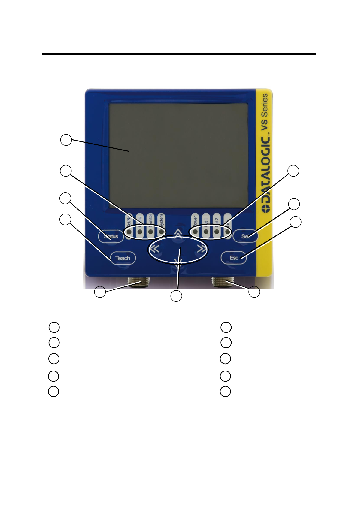
Monitor (color 3.5" LCD 320x240 pixel)
1
TEACH Button
4
Status LEDs
2
Power Supply Connector
5
ARROW Buttons
6
Ethernet Network Connector
7
STATUS Button
3
ESC Button
8
SET Button
9
Power, OUT, ETH Link LEDs
10
1 2 3
4 5 6 7 8
9
10
GENERAL VIEW
DataVS2-VSM
Figure A
Page 7

GENERAL INFORMATION
1
1
NOTE
This refers to information of particular interest.
NOTE
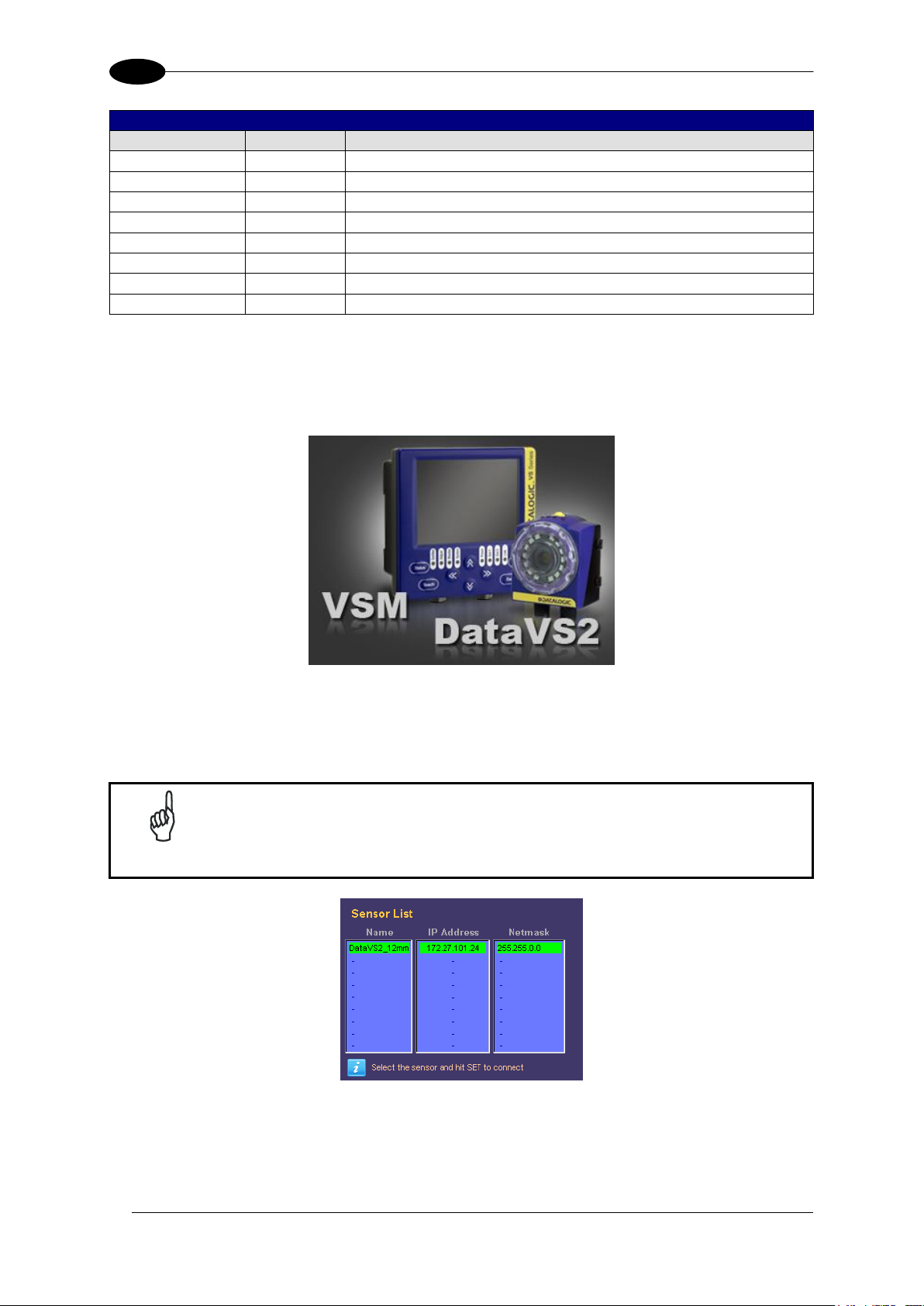
The Datalogic DataVS2 vision sensor (machine vision) is easy to use and
has advanced inspection functions which makes it very suitable to many
different fields (quality control on production lines or automatic material
handling are just a few examples).
1 GENERAL INFORMATION
1.1 CONVENTIONS USED IN THE MANUAL
This manual was developed to provide clear and precise information on how to use the
DataVS2 VSM system.
1.2 GENERAL DESCRIPTION
The VSM is a visualisation and control device compatible will all the vision sensors of the
DataVS2 series. The monitor can be connected directly to one sensor or installed on a
network.
Once connected, the VSM monitor displays the processed images together with the results
of the analysis tools as well as a few statistics relative to control results. The device controls
the functioning of the vision sensors as well as changing the parameters in order to adapt
and vary the DataVS2 configuration without using a PC.
VSM allows simple and rapid sensor setting. The user can immediately access all the
functions: change an inspection, modify in real time the inspection in execution, view results
and statistics.
Once the DataVS2 settings have been completed, the VSM can be used to view the results
of the current inspection, or it can be disconnected and the sensor will continue to function in
stand-alone mode.
Thanks to the wide range of functions, the VSM represents an excellent and complete HMI
interface, ideal for automatic production lines controlled by operators.
Page 8
DATAVS2-VSM INSTRUCTION MANUAL
2
2
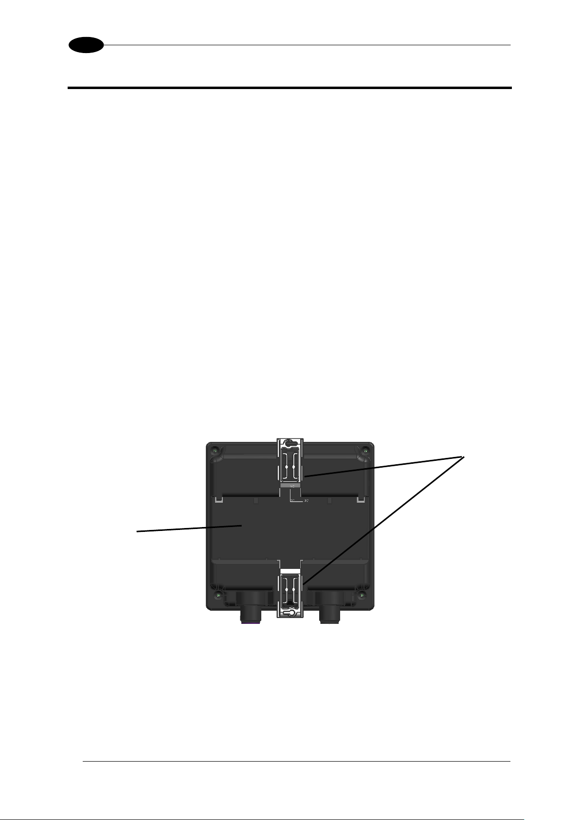
Locking clips
Slot for the
DIN guide
2 INSTALLATION
2.1 SAFETY RECOMMENDATIONS
Read the instruction manual carefully before installing the sensor and VSM.
Make sure that the product is suitable for the system that you intend to set up.
Connect the cables to the devices with the poles in the right direction.
Power up the devices following the instructions contained in the Manual.
Protect all devices against dust, dirt and humidity.
Never spill liquids on the devices
It is strictly prohibited to use DataVS2 in applications where the safety of persons
and/or things is guaranteed by the correct functioning of the device.
Always comply with all safety rules and regulations.
Never use the devices in environments where there is a risk of explosion.
Do not subject the devices to strong and continuous vibration.
2.2 DATAVS2 VSM DIN RAIL MOUNTING
There is a slot on the rear of the VSM which allows the user to connect the device to a DIN
guide.
Page 9
INSTALLATION
3
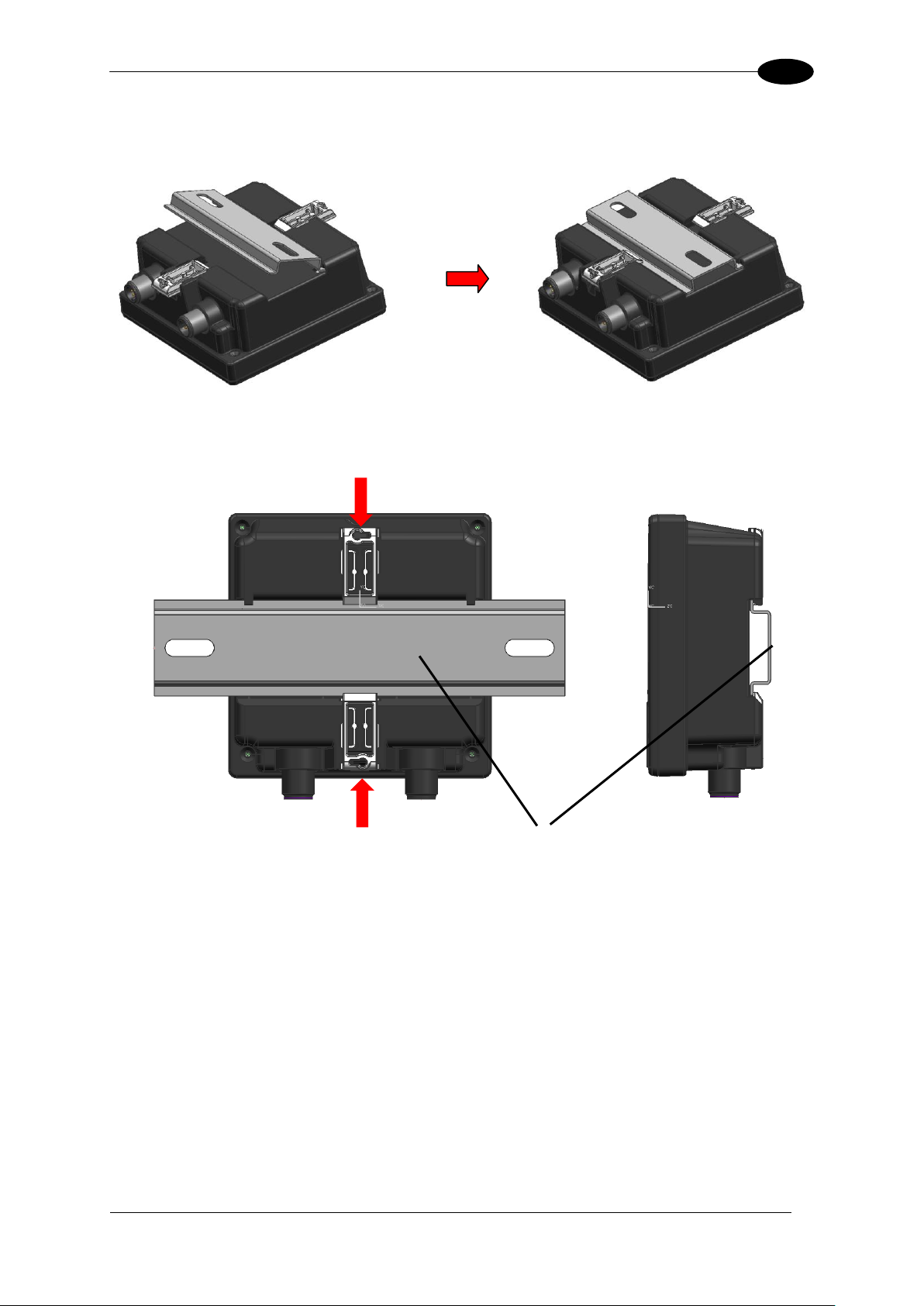
2
DIN Guide
Wedge the VSM unit in the DIN rail. First set the upper part of the monitor and then press
down the lower part.
Once inserted, block the VSM monitor using the two white side locking clips.
Page 10

DATAVS2-VSM INSTRUCTION MANUAL
4
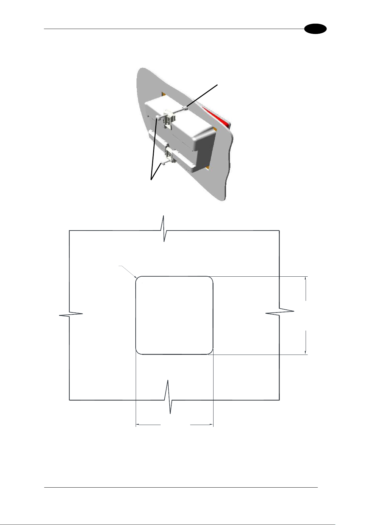
2
Rubber seal
2.3 DATAVS2 VSM PANEL MOUNTING
The VSM can also be installed on a panel. All the accessories for this mounting are included
in the package.
First, carefully place the rubber seal around the VSM unit.
Page 11
INSTALLATION
5
2
92
±0.2
[3.62
±0.01
]
92
±0.2
[3.62
±0.01
]
R7.5
[R0.30]
Locking screw
Cap
Then fix the VSM on the panel using the two locking screws and the two rubber caps.
Page 12
6
3
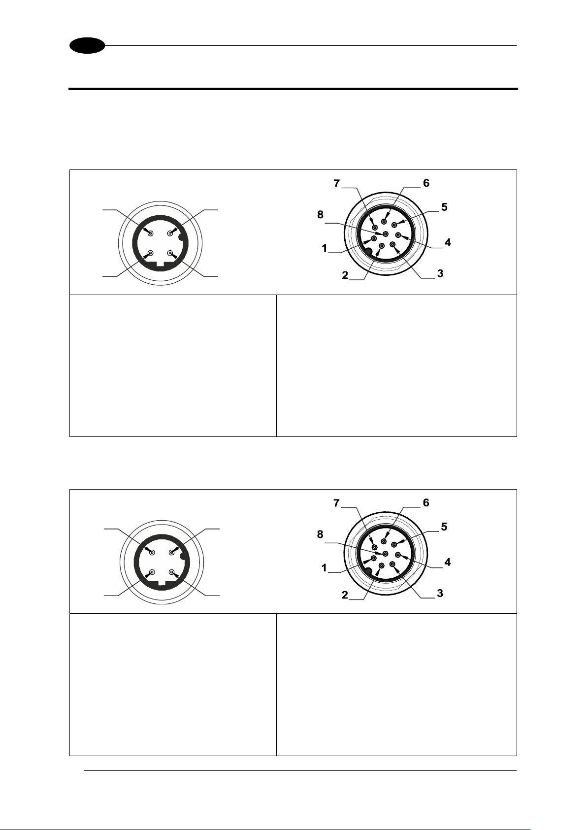
3 ELECTRICAL CONNECTIONS
3
1
2
4
M12 Reverse Keyed 4-Pin Male
(Ethernet connection)
pin 1: Ethernet RX+
pin 2: Ethernet TX+
pin 3: Ethernet RX-
pin 4: Ethernet TX-
M12 8-Pin Male
(power supply and I/O)
pin 1: white : Digital Input 1
pin 2: brown: +24 Vdc
pin 3: green : Output 4 /
Strobe for external illuminator
pin 4: yellow: Output 1
pin 5: grey: Output 2
pin 6: pink: Output 3
pin 7: blue: Ground
pin 8: red: External Trigger
3
1
2
4
M12 Reverse Keyed 4-Pin Male
(Ethernet connection)
pin 1: Ethernet RX+
pin 2: Ethernet TX+
pin 3: Ethernet RX-
pin 4: Ethernet TX-
M12 8-Pin Male
(power supply and I/O)
pin 1: white : RS-232 Rx
pin 2: brown: +24 Vdc
pin 3: green : Output 4 /
Strobe for External Illuminator
pin 4: yellow: Output 1
pin 5: grey: Output 2
pin 6: pink : RS-232 Tx
pin 7: blue: Ground
pin 8: red: External Trigger
3.1 PINOUTS
3.1.1 DataVS2 OBJ/AOR Sensor
DATAVS2-VSM INSTRUCTION MANUAL
3.1.2 DataVS2 ID/PRO Sensor
Page 13
ELECTRICAL CONNECTIONS
7
3
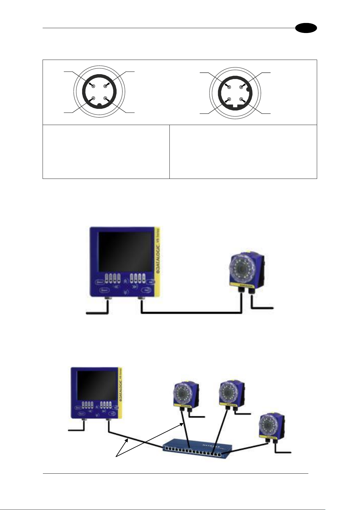
3
1
2
4
3
1
2
4
M12 4-Pin Male
(Power supply)
pin 1: +24 Vdc
pin 2: Reserved
pin 3: GROUND
pin 4: Reserved
M12 Reverse Keyed 4-Pin Male
(Ethernet connection)
pin 1: Ethernet RX+
pin 2: Ethernet TX+
pin 3: Ethernet RX-
pin 4: Ethernet TX-
Power
DATAVS-CV-VSM-xx
Power
LAN
Power
Power
DATAVS-CV-RJ45D-03
Power
Power
3.1.3 VSM Monitor
3.2 POINT-TO-POINT CONNECTION
Connect DataVS2 to VSM using the specific connection cable (DataVS-CV-VSM-xx).
3.3 LAN CONNECTION
Connect DataVS2 and VSM to LAN using the specific connection cable (DataVS-CV-RJ45D-
03).
Page 14
DATAVS2-VSM INSTRUCTION MANUAL
8
3
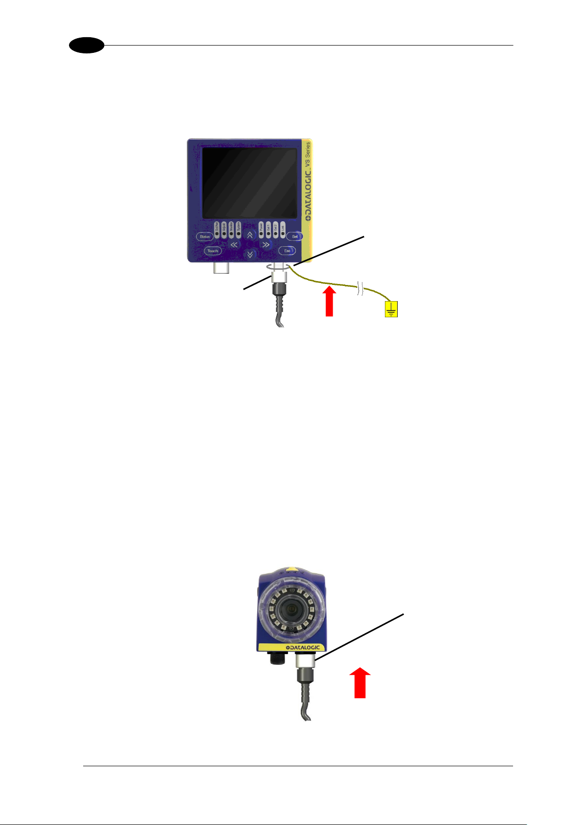
Washer M12
Ring Nut
PWR-I/O
3.4 GROUND CONNECTION
To comply with the EMC requirements, the Ethernet cable shield has to be grounded. (Use
the yellow/green cable supplied with the VSM).
Insert the washer M12 on the yellow/green cable in the VSM connector and then screw the
Ethernet cable until the ring nut reaches the washer.
Warnings
Insert the cable into the correct connector following the key indications inside the
body
After inserting the cable, turn the ring nut anticlockwise to ensure connection
Never force the cable inside the connectors.
Make sure that every cable is connected to the right connector
Before disconnecting the cable, completely turn the ring nut anticlockwise
3.5 DATAVS2 POWER CONNECTION
Connect the power and I/O cable (CV-A1-36-B-xx) inserting it into the connector identified by the icon
(PWR-I/O).
Page 15

FIRST APPROACH TO VSM
9
4
BUTTON
Button ID
Main Functions
Status
Go to main menu (“System”)
Teach
Go to “Adjust” status
Set
Confirms selected option
Confirms setting value
Esc
Exit without saving
Back to previous screen
Arrows
Changes selected option
Movement/resizing of the ROI
Changes the parameters
4 FIRST APPROACH TO VSM
4.1 INTRODUCTION
The configuration of the DataVS2 vision sensor has to be made only through DataVS2 GUI.
To simplify the instructions described in this manual, the pressing of the buttons on the VSM
user interface will be indicated as follows:
4.2 VSM USER INTERFACE
The chart shown below provides a general overview of the user interface on the VSM user
interface. Please note however that the functions of the buttons vary according to the
operating mode selected by the user. Please consult the next chapters for further details on
how the system reacts to the pressing of such buttons.
Page 16
DATAVS2-VSM INSTRUCTION MANUAL
10
4
LED
LED ID
Colour
Meaning
Power
Green
VSM correctly powered
Out 1
Orange
Digital output 1 active
Out 2
Orange
Digital output 2 active
Link
Green
VSM correctly connected to LAN
Set/Net
Green
Current status: Setup
Adjust
Green
Current status: Adjust
Monitor
Green
Current status: Monitor
System
Green
Current status: System
NOTE
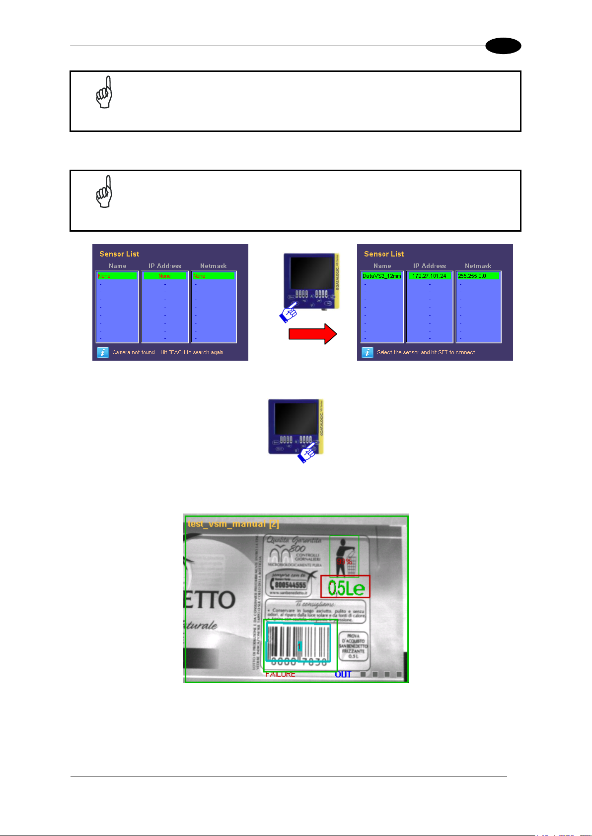
The VSM suggests to connect the last sensor used selecting it from the list
of DataVS2 (shown in green).
4.3 CONNECTION TO DATAVS2
When the VSM is powered, the welcome screen will be displayed on the monitor.
After a few seconds, a “Net Discovery” is automatically carried/out in order to find how many
DataVS2 are present in the LAN network.
At the end of the discovery, a panel will be displayed listing all the DataVS2s found.
Page 17
FIRST APPROACH TO VSM
11
4
NOTE
The maximum number of DataVS2 displayed in the list is 32.
NOTE
If no devices have been found in the first discovery, a new search can be
carried-out by pressing TEACH.
To connect a sensor, just select it from the list and press SET.
Once connected, the VSM enters in the monitor status displaying the inspection currently
being carried/out by the DataVS2.
If the field is out of focus, the user can adjust it by regulating directly the focus ring on the
sensor.
Page 18
DATAVS2-VSM INSTRUCTION MANUAL
12
5
Mode
Example
Enable
Description
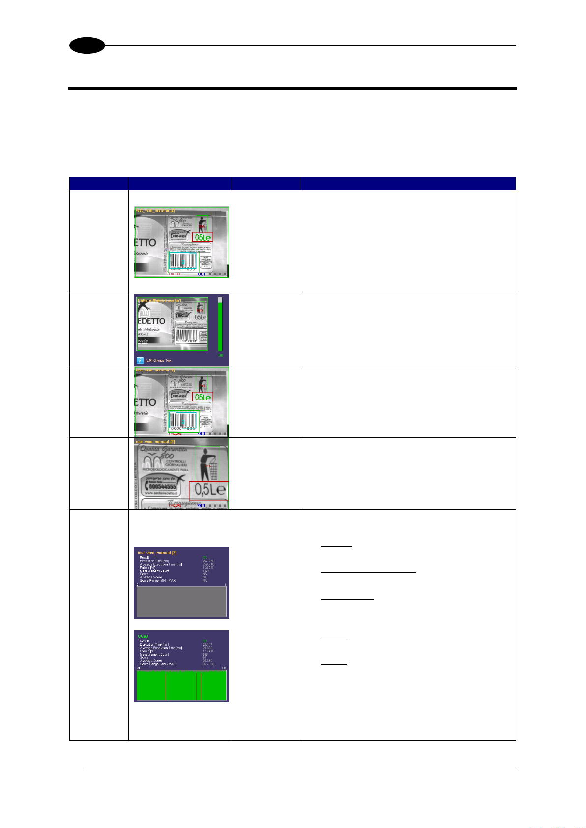
Standard
The monitor displays the sensor field focus
in full screen mode. The following
information is also displayed:
Inspection name and relative memory
slot
ROI
Inspection result
Logic value of the outputs
Tool
Result
DOWN
ARROW
This screen shows the tool result of the
current inspection.
The results of all the inspection tools can
be displayed using the RIGHT/LEFT
ARROWS.
Display
On
Condition
ESC
BUTTON
This mode displays only the images that
comply with the condition specified during
inspection configuration using the
DataVS2 GUI.
Zoom
Mode
UP
ARROW
An image of the sensor field focus is
displayed on the monitor with 200% zoom.
To move the zoom area, use the ARROW
buttons. Press ESC to exit zoom mode.
Statistics
SET
BUTTON
Statistics on the inspection results are
displayed on the monitor, including:
Result
Current inspection outcome
Execution time (ms)
Total inspection execution time
Failure (%)
% of failed inspections of the total
number executed
Score
Current inspection result
Etc…
The statistics of the single tools can be
displayed by pressing STATUS. Use
UP/DOWN ARROWS to scroll the tool
panels.
Use RIGHT/LEFT ARROWS to change
the scale of the graphics.
5 MONITORING AN INSPECTION
The “Monitor” mode allows the user to check the correct functioning of the inspection defined
previously.
The chart shown below provides a description of the main modes available and shows how
to enable viewing.
Page 19
INSPECTION CHANGE
13
6
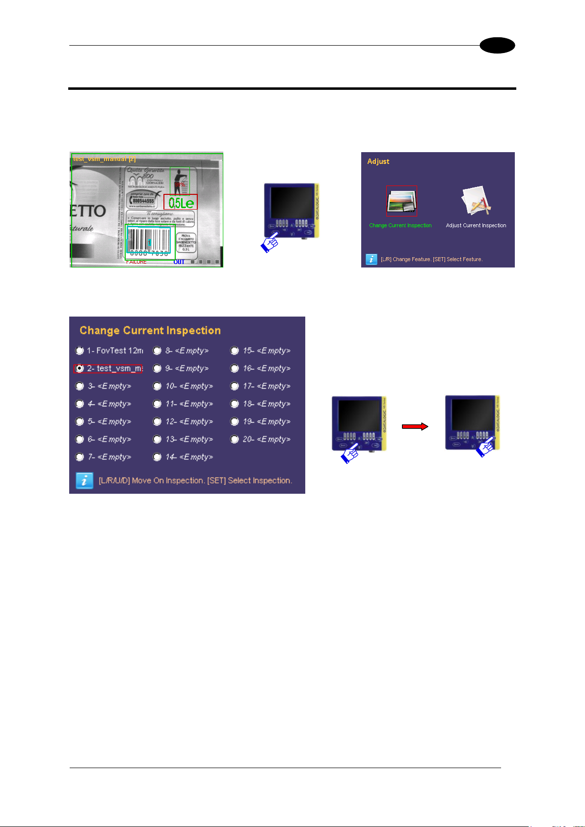
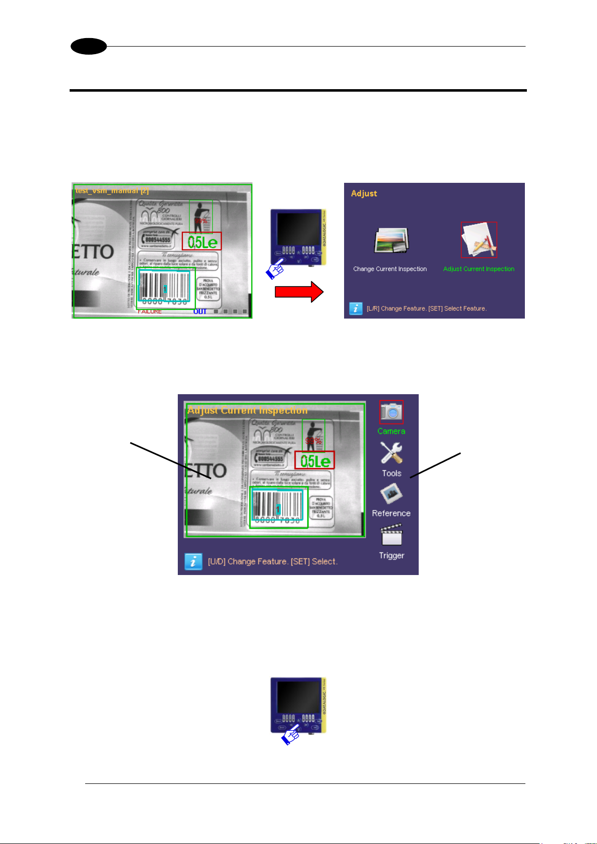
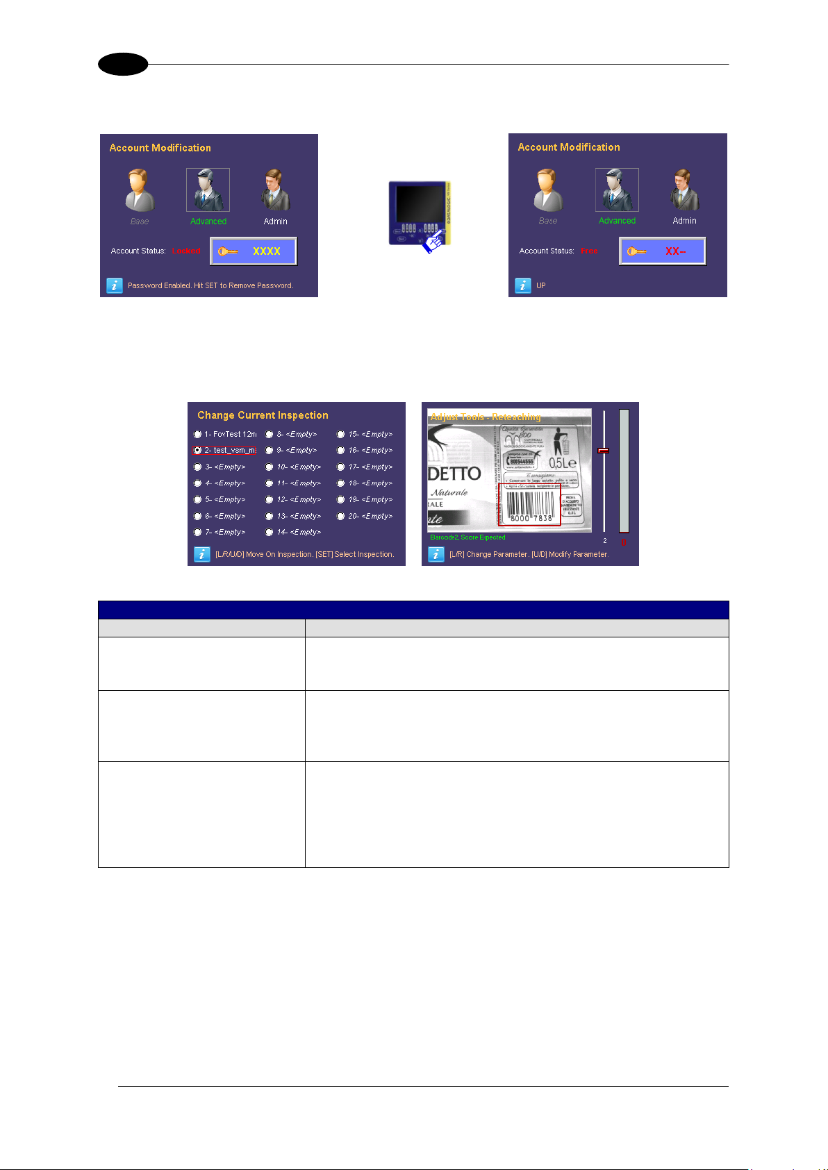
6 INSPECTION CHANGE
To change the inspection currently in execution on the DataVS2, the user must start from the
monitor screen and press TEACH. The selection panel will be displayed:
Press SET on “Change Current Inspection” to access another panel where the user can
select the inspection to carry-out.
Use the ARROWS to move the focus on the desired inspection and press SET to start the
inspection.
At this point DataVS2 carries-out the new inspection and the monitor status is restored.
Page 20
DATAVS2-VSM INSTRUCTION MANUAL
14
7
Configuration
Options
Field Range
7 INSPECTION PARAMETER CHANGE
7.1 CURRENT INSPECTION CHANGE
To change the sensor parameters, press TEACH in the monitor mode. The following panel is
displayed:
At this point the user can choose to change the current inspection or modify the parameters.
Selecting “Adjust Current Inspection” the user accesses the main panel of the Adjust
status:
As you can see in the image, the VSM is split into two main areas: the field range of the
camera and the configuration options available.
The image acquired by the sensor is displayed in the first area. The configuration options are
displayed on the right side of the monitor, where the user can scroll through the options using
the UP/DOWN ARROWS.
Page 21
INSPECTION PARAMETER CHANGE
15
7
Parameter
Description
Change
Exposure time
The exposure time identifies the period that
the lens remains open and allows light to
reach the CMOS mounted on the sensor.
Therefore, the longer the exposure time,
the brighter the image will be. On the other
hand, increasing the exposure times
increases the risk of acquiring blurred
images where the detail being monitored
moves at a certain speed. If the images of
objects that move quickly are not very
bright, it is recommended to adjust the gain
settings.
To adjust the exposure
time, move to the option
and use the RIGHT/LEFT
ARROW buttons.
Press STATUS to change
the scale of the slider
values.
(At each pressing the scale
is increased of one order
of magnitude).
Gain
The gain setting allows you to adjust the
brightness of the image acquired by the
sensor by amplifying the signal transmitted
by the CMOS to the processing unit.
Increasing the gain setting, however, also
increases the disturbance on the image
which decreases its quality.
To adjust the gain setting,
move to the option and use
the RIGHT/LEFT ARROW
buttons.
Illuminator
This parameter is referred to the illuminator
inside the sensor and only one of the three
options can be selected: OFF, ON and
POWER.
To adjust the gain setting,
move to the option and use
the RIGHT/LEFT ARROW
buttons.
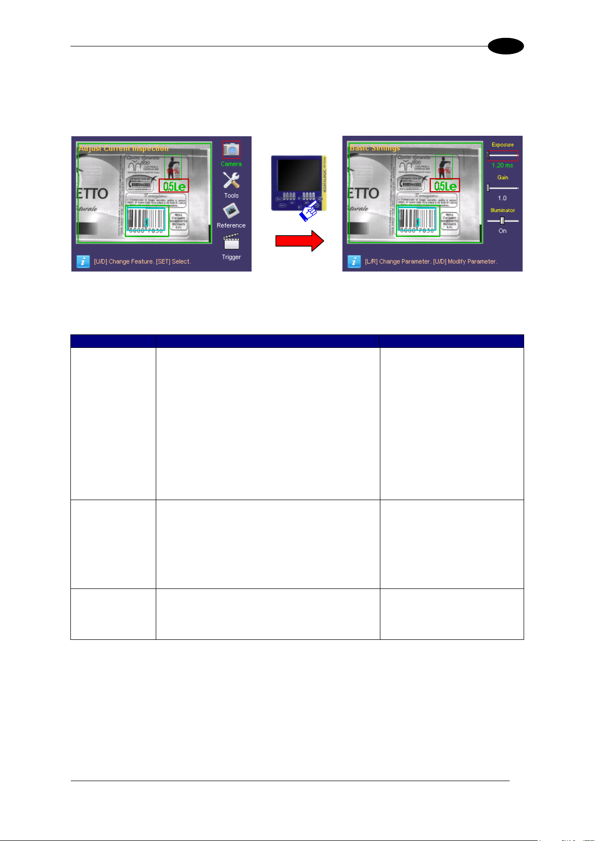
7.2 CAMERA PARAMETER CHANGE
Selecting the “Camera” option and pressing SET, the user accesses some DataVS2
parameters such as: exposure time, gain and illuminator operating mode.
The user can change the focus between the objects on the panel by using the UP/DOWN
ARROWS. To change the parameter value, once selected the focus, the user has to use the
RIGHT/LEFT ARROWS.
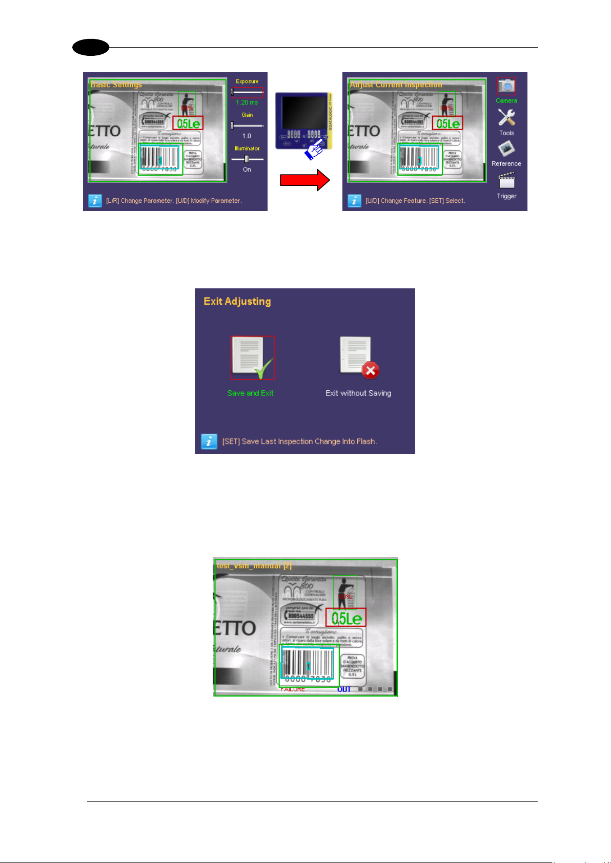
Once the camera settings have been completed, it is possible to return to the Setup menu by
pressing ESC.
Page 22
DATAVS2-VSM INSTRUCTION MANUAL
16
7
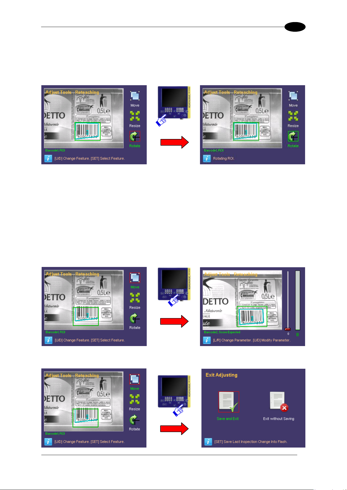
If no other change has to be made, press ESC to return to the “Monitor” status.
If inspection parameters have been changed, another panel will be displayed requesting the
saving of the changes:
To save the new data in the memory select “Save and Exit” using the SET button.
If the changes must have to be cancelled, select “Exit without Saving” using the SET
button.
At this point the system returns to the monitor status.
Page 23
INSPECTION PARAMETER CHANGE
17
7
NOTE
All the inspection parameters can be modified only if previously enabled
through the DataVS2 GUI panel. For further information, please refer to the
DataVS2 Instruction Manual.
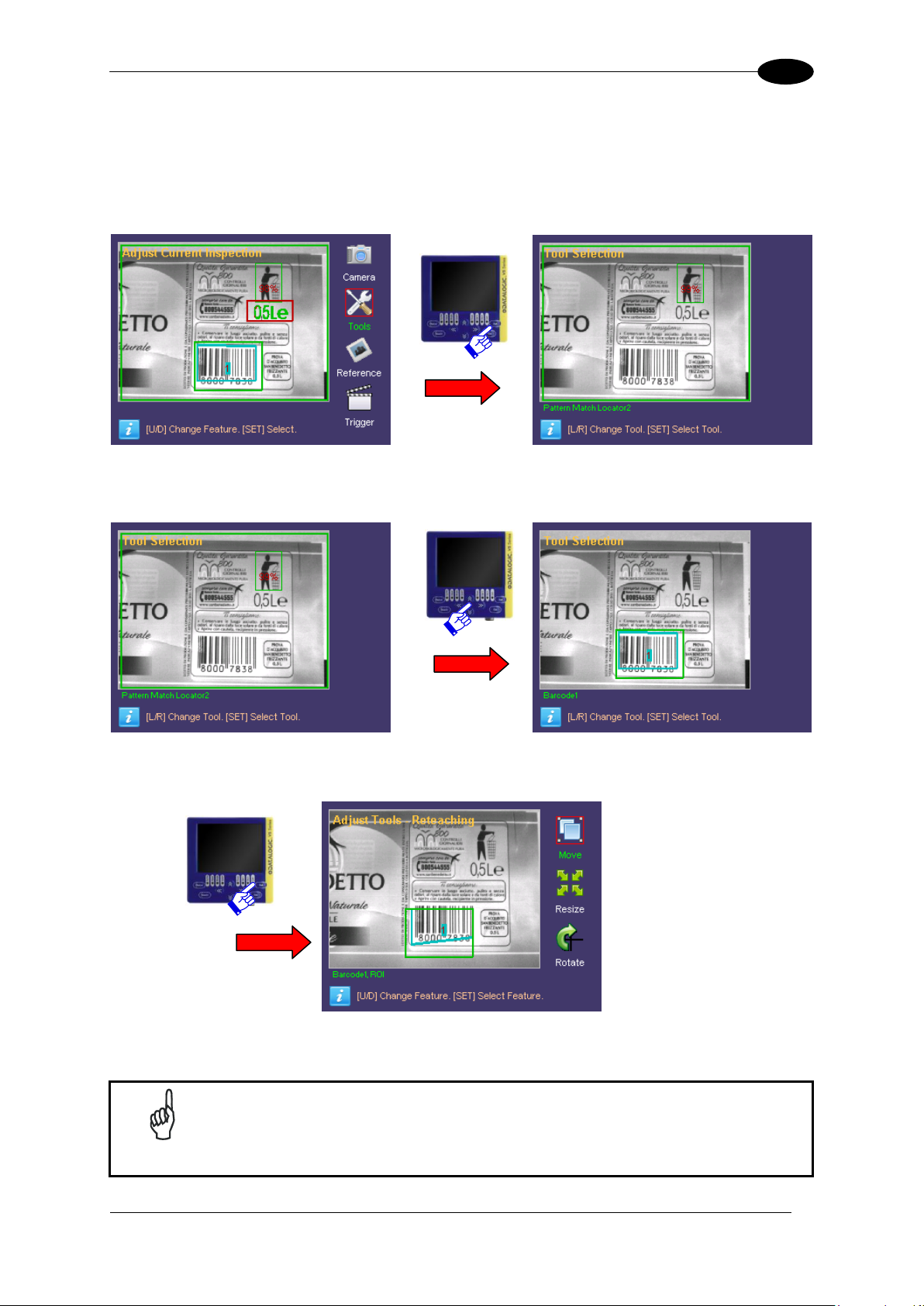
7.3 TOOL PARAMETERS CHANGE
7.3.1 Tool Selection
Press SET on the “Tools” icon in the “Adjust Current Inspection” panel.
The “Tool Selection” panel is displayed and the user can choose the tools to use.
All the inspection tools will be displayed one at time according to the creation order.
The user can scroll through the different tools using the RIGHT/LEFT ARROWS. Press SET
to confirm.
All the parameter change panels can be accessed from here on starting from the ROI panel
up to the last one with the parameters that can be changed using the selected tool.
Page 24
DATAVS2-VSM INSTRUCTION MANUAL
18
7
NOTE
For the tools characterized by two ROIs, such as the Pattern Match or 360°
Pattern Match, the VSM allows editing only the ROI research.
NOTE
Press TEACH to confirm. When exiting the change mode, the user is
requested to discard changes or save them definitively in the flash memory.
All changes will be cancelled by selecting “Exit without saving”.
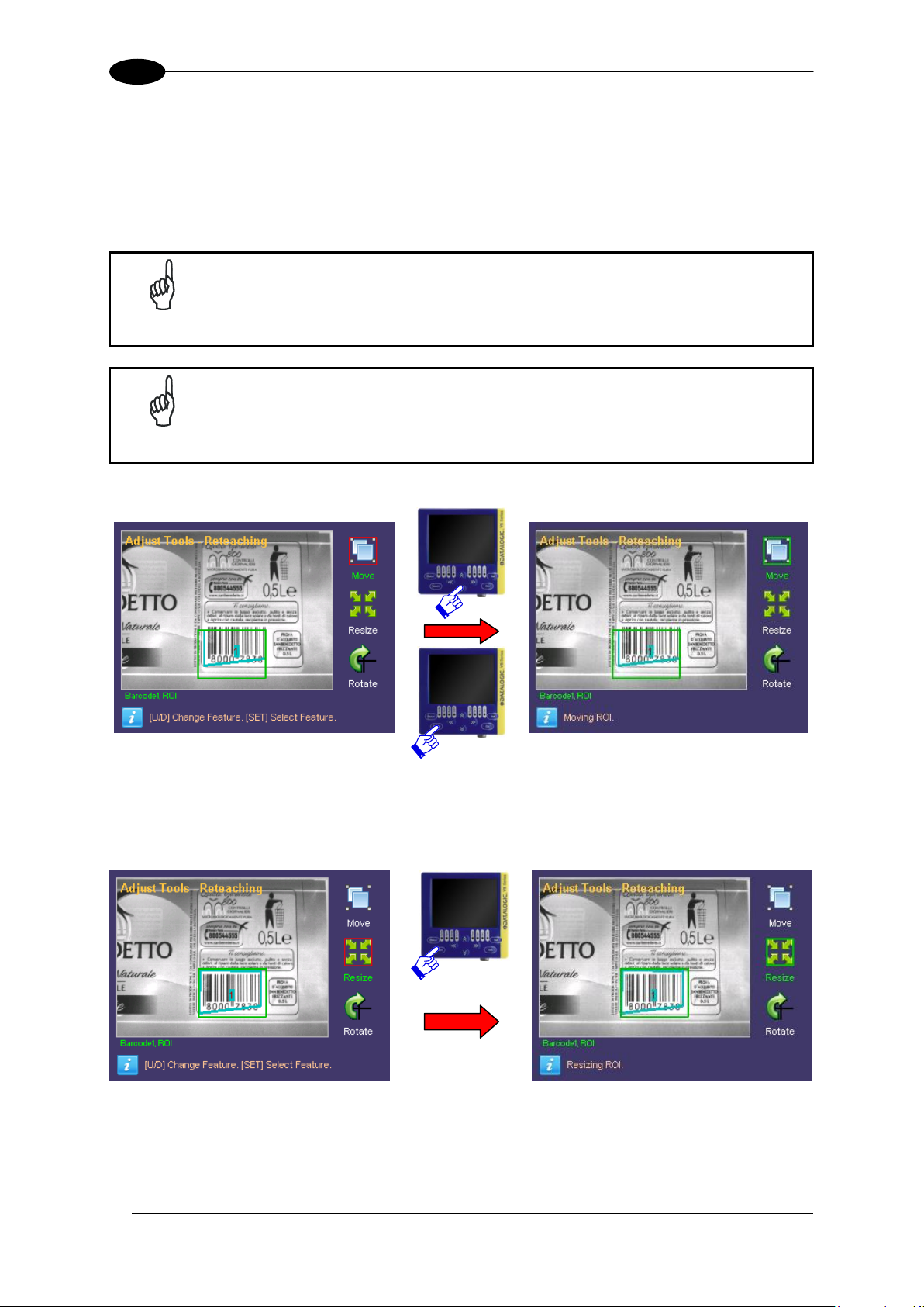
7.3.2 ROI Change
To modify a ROI, the tool must have been selected previously and the “Adjust Tools” panel
opened.
The following operations are possible: Move, Resize and Rotate.
MOVE:
Once selected “Move”, the focus is transferred in the field range and the ROI can be moved
using the ARROWS.Once you have achieved the desired position, press TEACH to save
changes. Press ESC to return to the Setup menu ignoring the changes made.
RESIZE:
If you wish to modify the ROI size, select the “Resize” option from the Setup menu (using
the SET button again). It is now possible to increase or decrease the ROI size using the
ARROW buttons.
Page 25
INSPECTION PARAMETER CHANGE
19
7
Once you have achieved the desired size, press the TEACH button to save the settings and
return to the Setup menu. Press the ESC button to return to the Setup menu without saving
the modifications (the system will request confirmation on the saving option).
ROTATE:
To rotate the ROI, select the “Rotate” option from the Setup menu (using the SET button
again). The ROI will rotate in a clockwise/anticlockwise directly depending of the
RIGHT/LEFT ARROW button pressed.
Once you have achieved the desired rotation angle, press TEACH to save the settings and
return to the Setup menu. Press ESC to return to the Setup menu ignoring the changes
made.
Once the changes on the ROI are completed, the user can exit from the “Adjust” mode or
proceed with the configuration of the single parameters of the selected tool.
All the parameters that can be changed by the DataVS2 GUI can be scrolled by pressing the
RIGHT/LEFT ARROWS.
To return to the “Monitor” mode the user must return to the higher level panels by pressing
ESC. If changes have been made, the user is requested to save or ignore them definitively.
Page 26

DATAVS2-VSM INSTRUCTION MANUAL
20
7
NOTE
The parameters that can be modified vary according to the tool and the
inspection selected.
Field size
Calculated
value
Current
setting
value
Setting name
7.3.3 Other Parameter Changes of the Selected Tool
This paragraph explains how to change the parameters that adjust the functioning of a tool.
The VSM monitor is divided as follows: the parameters that the user can change are
displayed on the right side, while the image captured by the sensor is displayed on the
remaining area. The name of the parameter currently in use is shown on the bottom of the
monitor.
The parameters are displayed one at a time, and so the RIGHT/LEFT ARROWS must be
used to pass from parameter to the another.
To change the current value, use the UP/DOWN ARROW. Each time the button is pressed,
the value associated to the slider, is increased or decreased of one unit (to change the value
faster keep the corresponding button pressed).
Page 27

INSPECTION PARAMETER CHANGE
21
7
7.4 REFERENCE IMAGE CHANGE
Select "Reference" and press SET to access the management screen of the reference
image.
The screen shows the current image, pressing TEACH you can activate the reference image
change procedure. After the press of TEACH button the first acquired image will be set as
new reference image of the current inspection.
Pressing STATUS you can see the current reference image. Pressing STATUS again
returns to the Reference image management screen.
Once you set the reference image, press the ESC key to return to the "Adjust current
inspection" menu.
Page 28

DATAVS2-VSM INSTRUCTION MANUAL
22
7
7.5 TRIGGER MODE CHANGE
Select "Trigger" and press SET to access the management screen of the trigger mode.
As you can see in the image, the VSM is split into two main areas: the parameters that the
user can change are displayed on the right side of the monitor, while the remaining area
displays the image acquired by the sensor.
At the bottom of the monitor also is shown the name of the selected trigger parameter;
Parameters that can be modified are “Trigger Mode” and “Trigger Delay”.
The user can scroll through the parameter using the UP/DOWN ARROWS.
To change the current value, use the UP/DOWN ARROW. Each time the button is pressed,
the value associated to the slider, is increased or decreased of one unit (to change the value
faster keep the corresponding button pressed).
Page 29

ADVANCED FUNCTIONS
23
8
NOTE
The “Disconnect” icon is displayed only when a DataVS2 is connected as it
indicates the active status of the sensor connection.
Indication of connected sensor
Network
Parameters
Data of DataVS2
connected
Product info
8 ADVANCED FUNCTIONS
The previous chapter described the procedure used to modify an inspection for DataVS2.
Further to the functions above-described, there are other user settings on the VSM monitor
which can be accessed from the System menu.
“System” menu is accesed from “Monitor” pressing STATUS.
8.1 MONITOR SETTINGS
This panel provides access to VSM information such as name, serial number, model, etc…
Moreover the IP and NetMask network parameters can be modified and the data of the last
DataVS2 connected can be displayed.
To change the network parameters, the user has to simply move the focus on the desired
value and use the UP/DOWN ARROWS to increase or decrease the current value.
To save the changes press SET.
Page 30

DATAVS2-VSM INSTRUCTION MANUAL
24
8
NOTE
Restart the device to apply correctly the changes.
NOTE
Restart DataVS2 to apply correctly the changes.
DataVS2 Info
unchangeable
Parameters
changeable
To return to main panel without saving, press ESC.
8.2 SENSOR SETTINGS
This panel, when a DataVS2 is connected, can display information such as name, firmware,
Hardware revision, MAC and modify the sensor network parameters: IP, Netmask and
DHCP...
To change the network parameters of DataVS2, the user has to simply move the focus on
the desired value and use the UP/DOWN ARROWS to increase or decrease the current
value.
To save the changes press SET.
To return to main panel without saving, press ESC.
Page 31

ADVANCED FUNCTIONS
25
8
NOTE
If panel is accessed without DataVS2 connection, the sensor area cannot be
accessed and the user can operate only on the VSM memory (only
cancellations).
Memories of
DataVS2
Memories of VSM
Controls for VSM
Transfer
DataVS2 – VSM
Transfer
VSM– DataVS2
Controls for
DataVS2
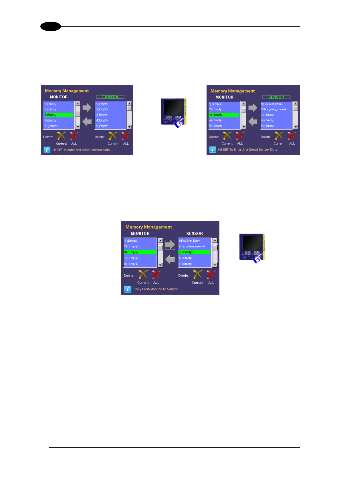
8.3 MEMORY MANAGEMENT
This paragraph explains how to transfer or cancel a memory slot between VSM and
DataVS2.
At this point the user can select the “Memory Management” icon and press SET. The
following panel is displayed:
As shown in the figure, the panel is divided in two: a VSM area (concerning the local
memory) and a DataVS2 area (remote device memory).
8.3.1 Slot Selection (VSM)
To select a memory slot to use, the focus must be moved on the “MONITOR” label using the
ARROWS and SET must be pressed.
Once done, the focus is moved in the list of slots where the user can scroll through the
memories only using the UP/DOWN ARROWS
Press SET to confirm the slot currently selected.
At this point, the focus returns outside the memory area and allows navigation between the
other buttons.
Page 32
DATAVS2-VSM INSTRUCTION MANUAL
26
8
8.3.2 Slot Selection (DataVS2)
The slot selection is similar to the VSM one: the focus must be moved using the ARROWS
on the “SENSOR” label and SET must be pressed. The focus will be moved inside the
memory list and once chosen the desired one press SET to confirm.
Once selected both memory slots, the transfer operations can be made.
8.3.3 Transfer from VSM to DataVS2
To transfer the memory slot from VSM to DataVS2 (after selecting both the source as well as
the destination) move the focus on the “Arrow on Right” button and press SET.
At this point the information label will request another operation confirmation, to proceed
press ARROW UP, otherwise press ARROW DOWN to abandon.
If confermed, the data will be transferred between VSM and DataVS2. As soon as the
operation has finished, an information label will display the result and a refresh of the panel
names will be made.
Page 33
ADVANCED FUNCTIONS
27
8
Confirm
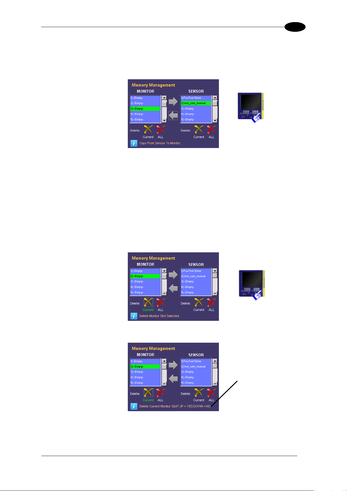
8.3.4 Transfer from DataVS2 to VSM
To transfer the memory slot from DataVS2 to VSM (after selecting both the source as well as
the destination) move the focus on the “Arrow on Left” button and press SET.
At this point the information label will request another operation confirmation, to proceed
press ARROW UP, otherwise press ARROW DOWN to abandon.
If confermed,the data will be transferred between VSM and DataVS2. As soon as the
operation has finished, an information label will display the result and a refresh of the panel
names will be made.
8.3.5 Cancellation of a VSM Slot
First select the desired slot (refer to previous paragraph “Selection of slot (VSM)”).
Then move the focus on “Delete Current” button (on the bottom left side of the screen) and
press SET to confirm:
At this point the information label will request another operation confirmation:
To proceed press ARROW UP otherwise, press ARROW DOWN to abandon. In both cases,
the information label will display the operation result and a refresh of the panel names will be
made.
Page 34
DATAVS2-VSM INSTRUCTION MANUAL
28
8
NOTA
It is not possibile to delete actual running inspection.
Confirm
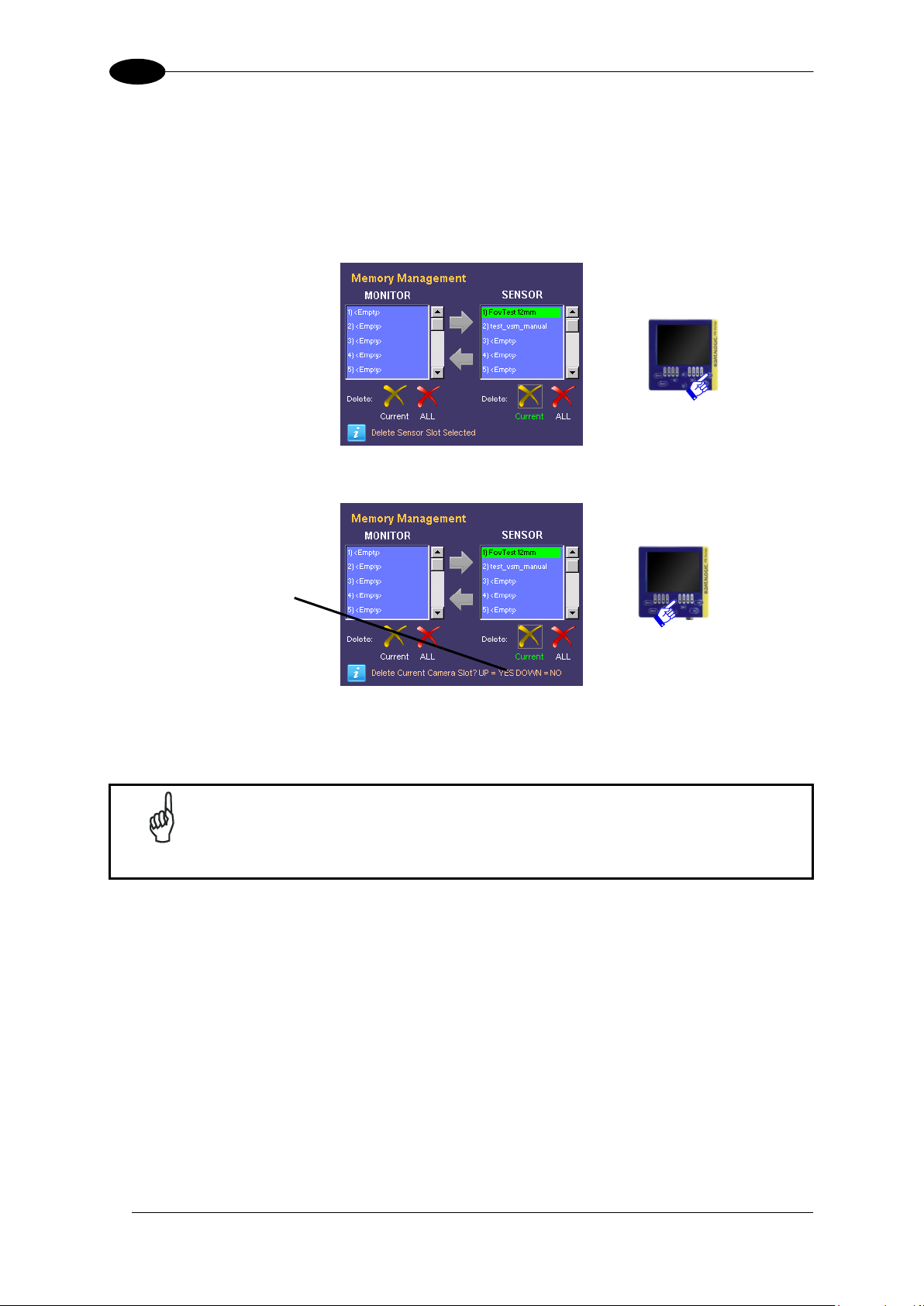
8.3.6 Cancellation of a DataVS2 Slot
Just like the VSM slots, the desired slot has to be selected (refer to previous paragraph
“Selection of slot (DataVS2)”). Obviously the monitor must be connected to a sensor to
access its memory.
Then move the focus on “Delete Current” button (on the bottom right side of the screen)
and press SET to confirm:
Another operation confirmation is requested also for the DataVS2 slots:
To proceed press ARROW UP otherwise, press ARROW DOWN to abandon. In both cases,
the information label will display the operation result and a refresh of the panel names will be
made.
8.3.7 Cancellation of all the VSM Slots
To cancel all the VSM memory slots no specific slot has to be selected but the user must
only move the focus on the “Delete ALL” icon on the bottom left side of the screen and
press SET.
Page 35
ADVANCED FUNCTIONS
29
8
NOTA
With this command all the inspections, with the exception of the actual
running one, will be deleted..
Another confirmation will be requested. To proceed press ARROW UP otherwise, press
ARROW DOWN to abandon. In both cases, the information label will display the operation
result and a refresh of the panel names will be made.
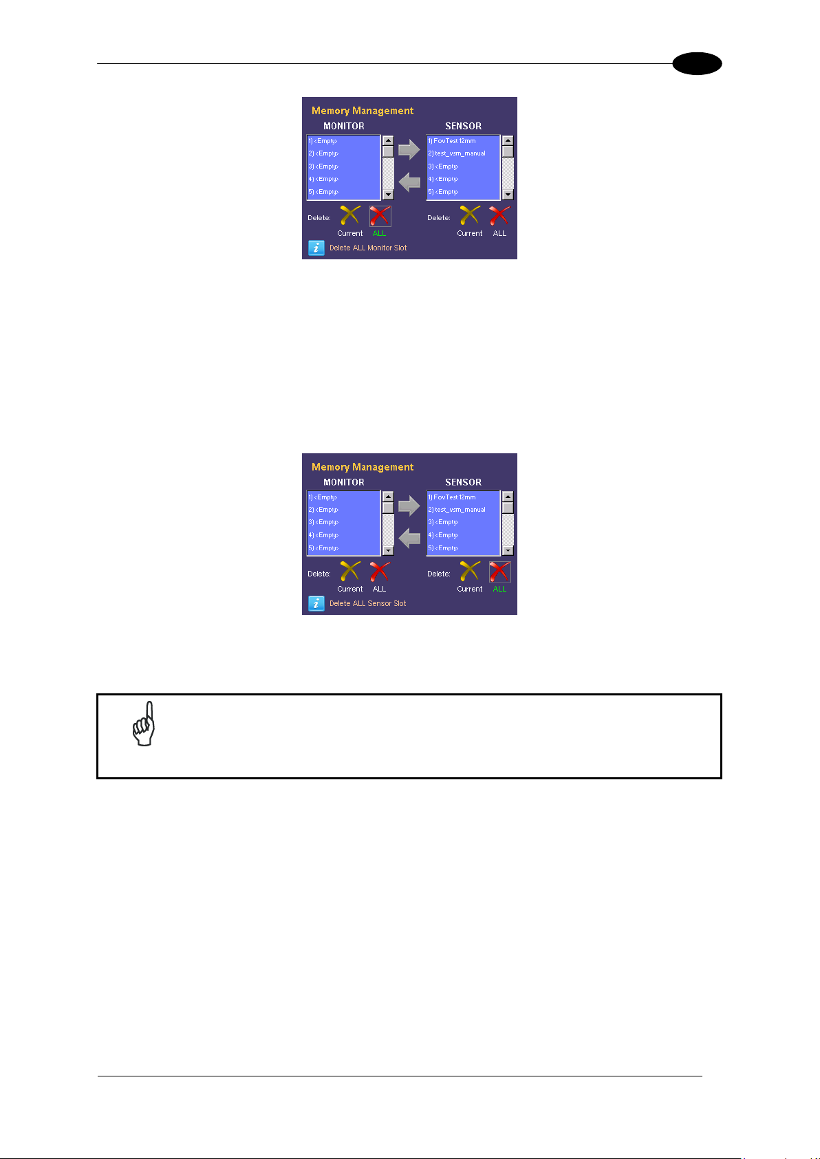
8.3.8 Cancellation of all the DataVS2 Slots
To cancel all the DataVS2 memory slots no specific slot has to be selected but the user must
only move the focus on the “Delete ALL” icon on the bottom right side of the screen and
press SET.
Another confirmation will be requested. To proceed press ARROW UP otherwise, press
ARROW DOWN to abandon. In both cases, the information label will display the operation
result and a refresh of the panel names will be made.
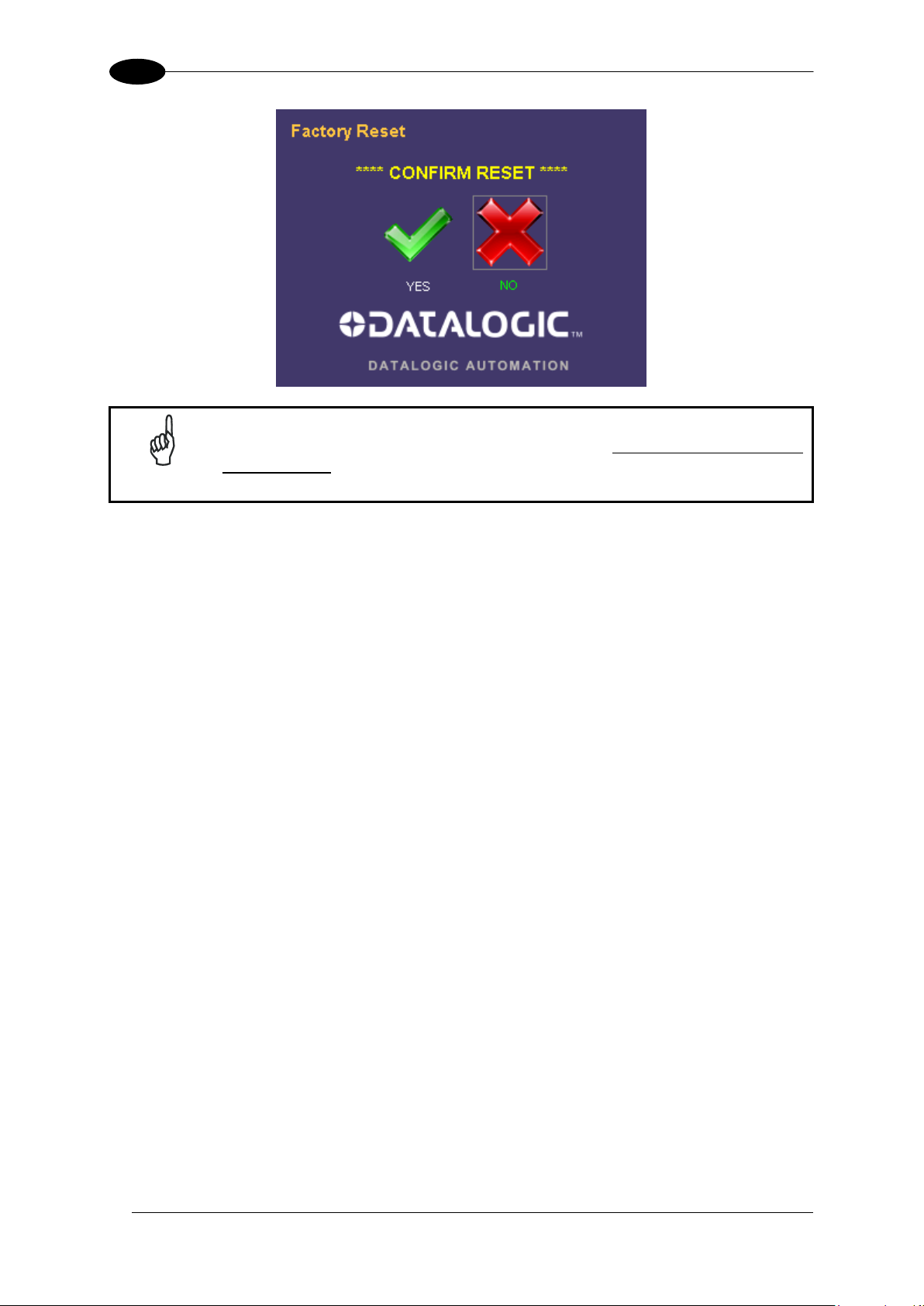
8.4 FACTORY RESET
This panel can be accessed only when no DataVS2 are connected and when the factory
reset of the VSM has to be restored.
All the memory slots are going to be cancelled, the network parameters changed and
passwords cancelled.
Page 36
DATAVS2-VSM INSTRUCTION MANUAL
30
8
NOTE
The system reset requires the VSM restart and the loss of all the data stored
in the memory.
Page 37
ADVANCED FUNCTIONS
31
8
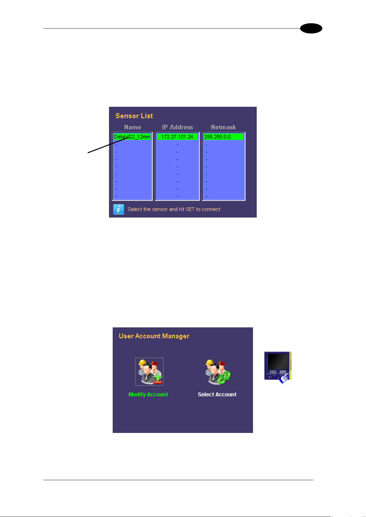
Selected sensor
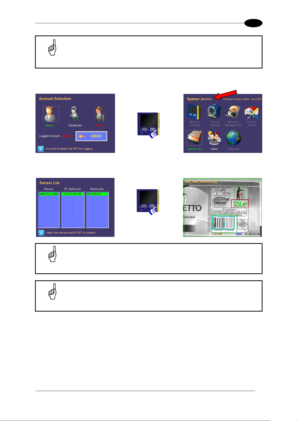
8.5 SENSOR LIST
The “Sensor List” panel, after having made a discovery, lists the DataVS2 present in the
subnet.
To connect a sensor the user just has to select it from the list with the UP/DOWN ARROWS
and press SET.
Once the connection has been established, the VSM returns immediately to the monitor
mode.
8.6 USERS
This panel allows the user to set a password to protect the system. This protects the sensor
against accidental or unauthorised modifications. In the factory setting the password is
disabled for all accounts.
Firstly, the operation to effect on the profiles must be selected: “Selection” or “Modify” and
then press SET.
Page 38

32
8
The account selection panel is displayed as follows:
NOTE
Each user logins in using the administrator account until a new password is
memorised.
User typology
Password field
Info on account
Information Label
DATAVS2-VSM INSTRUCTION MANUAL
To enable the administrator password, the user must access “Modify Account”, select
“Admin” and press SET.
The user can now digit a new password made up of a sequence of four keyboard buttons
(ARROW UP/DOWN/RIGHT/LEFT).
Once the password has been entered, press SET to confirm. The password will be saved
and each time the user wants to login as administrator, the “Admin” account must be
selected and the password entered.
Page 39
ADVANCED FUNCTIONS
33
8
NOTE
When the administrator password has been forgotten, the VSM can be
unblocked with the recovery password ARROW UP, ARROW LEFT,
ARROW RIGHT, ARROW RIGHT. At the end of the procedure remember
to cancel the old password and set a new one in the “Modify Account”
panel.
NOTE
After a “Factory Reset”, all the passwords are cancelled and the
administrator account is restored as default.
NOTE
The “Advanced” account can be activated only after activating the
“Admin” account.
By selecting the “Base” user, the majority of the advanced functions of the VSM cannot be
accessed.
Only the “Sensor List” panel can be displayed, as well as the sensor to select for
connection and the visualisation in “Monitor” during inspection execution.
To select the “Advanced” user, the administrator account has to be first activated.
Page 40
DATAVS2-VSM INSTRUCTION MANUAL
34
8
USER RIGHTS
Account
Main Functions
Base
This user can only view the current status of the inspection
(“Monitor” mode) and cannot access any of the advanced
functions panels.
Advanced
This user can be selected only after the administrator
account has enabled the profile.
Has limited rights and can monitor the status of the current
inspection, change it and modify tool parameters.
Admin
(User enabled by default when no password is set and after
every “Factory Reset”.)
This user controls completely the device, can manage all
controls, scroll through all the panels and can create and/or
cancel other users.
In “Modify Account” mode the user has to select “Advanced” and then save a password.
After this, the account will be active and only a part of the advanced functions enabled.
Besides the basic rights, the inspection can be changed and the parameters of the relative
tools modified.
Page 41
ADVANCED FUNCTIONS
35
8
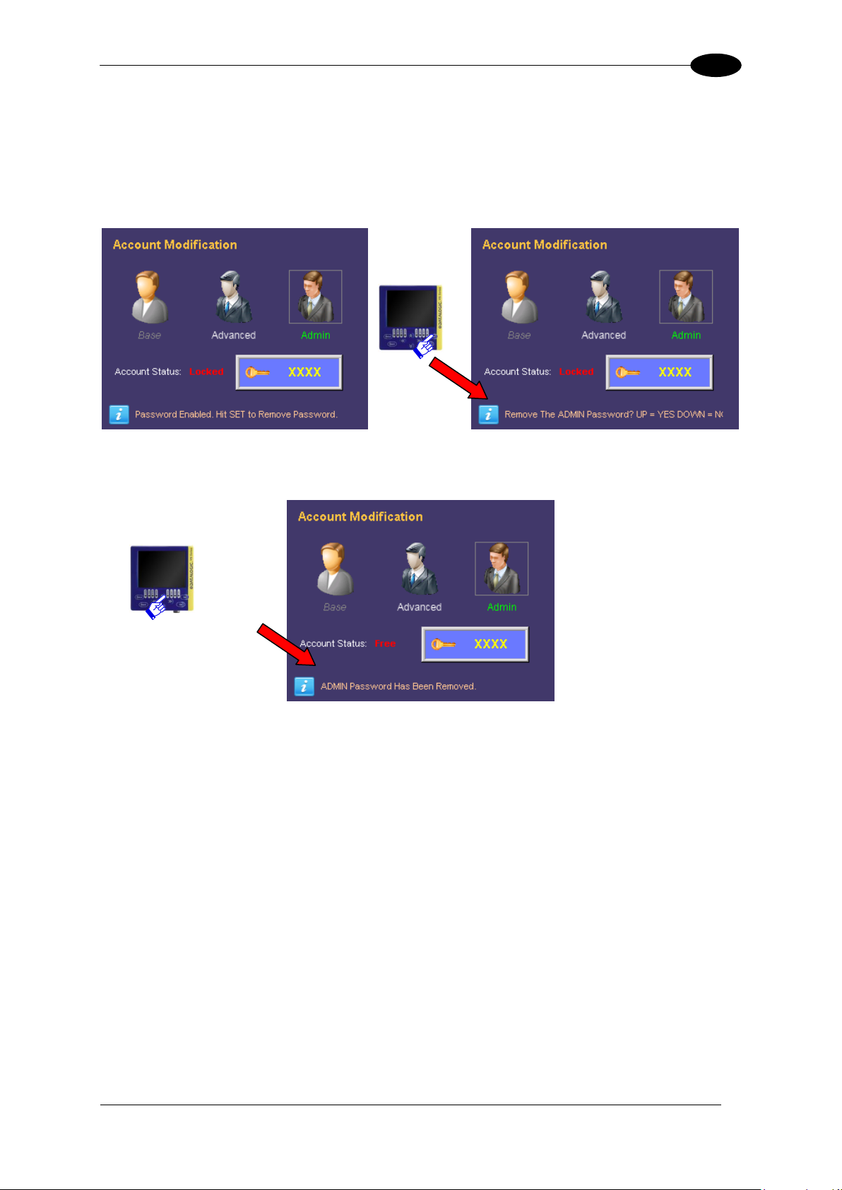
8.6.1 Removal of the Password
To disable all the accounts and remove the administrator password, the user must log in as
“Admin”.
Access “Modify Account”, select “Admin” user and press SET.
At this point the system requests the user to confirm the cancellation of the password. To
confirm press ARROW UP.
Page 42

DATAVS2-VSM INSTRUCTION MANUAL
36
8
NOTE
If the sensor is connected the “Sensor List” and “Factory Reset” panels
cannot be accessed.
8.7 LANGUAGE
Through this panel you can change the language of the VSM, current language is written in
the upper right side of screen. To set up a new language, choose the one you want with the
RIGHT/LEFT ARROW and press SET.
8.8 DISCONNECT
The “Disconnect” icon is displayed on the “System” panel only when connected to a
DataVs2. This indicates that the sensor is still connected and allows the user to disconnect
from the device.
If disconnected, to reconnect a DataVS2 or another device, the user must access the
“Sensor List” panel and select it from the list.
Page 43

DATAVS2 GUI CONNECTION
37
9
Parameters:
Description
Find sensor
DataVS2 GUI searches for all the connected
sensors/monitors and lists them in the CONTROL PANEL
Connect to …
DataVS2 GUI will connect the sensor/monitor whose
address corresponds to the IP address displayed
9 DATAVS2 GUI CONNECTION
To connect the VSM to DataVS2 GUI the “On Line“ mode must be selected from the specific
interface.
After having selected the relative radio button, the following screen will appear:
If “Find sensor” has been selected, the software will initially show a window with a progress
bar and, if any devices are connected, it will show this screen in the Control Panel present on
the right side of the main window:
Page 44

DATAVS2-VSM INSTRUCTION MANUAL
38
9
NOTE
If the line relevant to the desired device is highlighted in red, the connection
cannot be established. In this case we suggest to check the IP address and
Subnet Mask
The control panel will display a list of all the DataVS2/VSMs found by the “Find sensor”
function. The following information will be shown for each device:
The IP address;
The name;
An indication on the possibility of creating a connection (line highlighted in green) or
not (line highlighted in red);
A check box to select the DataVS2/VSM to reach.
To connect, check the box relative to the VSM and click on Connect. If connection is
successful the DataVS2 GUI will display the “VSM setting” panel.
9.1 VSM GENERAL INFORMATION
This window displays general information on VSM to which you are connected. Of the
parameters displayed, you can change:
the name of the VSM
IP address
Subnet Mask
After defining the new values, if you want to confirm those changes, you must click the Apply
button.
Page 45

DATAVS2 GUI CONNECTION
39
9
9.2 VSM MEMORY SETTINGS
This window shows the memory status of the VSM to which you are connected.
It also allows you to save on VSM PC inspections by pressing the button "Save On VSM”;
To save on PC the inspections saved on the memory of VSM by pressing the button "Save
On PC";
To cancel inspections of VSM by pressing the button"Delete".
Page 46

DATAVS2-VSM INSTRUCTION MANUAL
40
9
9.3 FIRMWARE UPDATE
The “VSM firmware updating” section can be accessed from the “VSM setting” panel and is
displayed as follows:
Page 47

DATAVS2 GUI CONNECTION
41
9
Parameters:
Description
Current Firmware
Version of Firmware currently executed on the connected
VSM.
Choose File
Press this button to select the Firmware file to be loaded on
the sensor. A dialogue window will then allow the user to
choose the “Desired Firmware” file saved in the PC.
After selecting the desired firmware and pressing “OK” in the
dialogue window, the firmware version selected will be
displayed in the “Desired Firmware” field.
Update Firmware
Press this button to update firmware in execution on the
connected VSM.
Two types of firmware updates are possible:
firmware upgrade: more recent firmware version, with
respect to the one currently in execution, is loaded on
the VSM;
firmware downgrade: a less recent firmware version,
with respect to the one currently in execution, is loaded
on the VSM.
Note: if this button is disabled, the selected firmware cannot
be loaded on the connected VSM due to Hardware version
incompatibility. In this case please select a different
firmware.
Note: after having updated the VSM firmware, the DataVS2
GUI will disconnect from the device and the VSM has to be
restarted.
Warning !! never power Down the VSM during Firmware
update procedure. The Monitor will restart by self at the end
of the update sequence.
Page 48
DATAVS2-VSM INSTRUCTION MANUAL
42
10
NOTE
Please enter Recovery Mode only if the sensor is not working and you are
not able to establish a communication with the sensor via the DataVS2
Graphic User Interface.
NOTE
The Recovery Mode is only intended for troubleshooting. The sensor in
Recovery Mode cannot be used for machine control.
10 RECOVERY MODE
In case of software crash, it is possible to run a recovery firmware on the device with a basic
communication service to restore the working environment.
In order to launch the recovery mode, power up the VSM, wait until the four status LEDs
(Set/Net, Adjust, Monitor e System) turn on in sequence, then press the STATUS button and
then the ESC button. The two Output LEDs start blinking, signalling that the recovery
firmware is running.
The VSM can be connected to the DataVS2 GUI in the recovery condition and perform the
following operations:
Update monitor firmware
Change VSM memory settings
Change monitor general information
10.1 RECOVERY PROCEDURE
In this paragraph you will find a simple recovery procedure to follow in case of monitor
malfunctioning.
Please follow the steps listed below whenever your VSM is not working properly:
1. Power on the monitor in Recovery Mode.
2. Open the DataVS2 GUI
3. From the STEP 1 select Online and connect to the monitor
4. Select “VSM Firmware Update” tab, choose the firmware file by clicking on “Choose
File” button and lastly click on “Update Firmware”.
5. Wait until the end of the update procedure. The interface gets automatically
disconnected from the monitor.
6. VSM restarts automatically. Verify that now it is working properly (i.e. it displays the
available sensor list panel).
Page 49

RECOVERY MODE
43
10
NOTE
If you are not able to connect to the VSM through the DataVS2 GUI, please
contact Sales Service.
Page 50

DATAVS2-VSM INSTRUCTION MANUAL
44
11
11 CHECKS AND PERIODIC MAINTENANCE
Correct system maintenance is necessary to remove dust or foreign objects from the VSM
display.
Remove dust using a soft cloth, if necessary dampened with a neutral detergent solution.
Avoid using:
detergents which contain alcohol or solvents
wool or synthetic cloths
Refer to the Datalogic website (www. datalogic.com) to verify the availability of new firmware
updates. To check the firmware version and date on your system, please refer to the System
Monitor Settings menu.
Page 51

WARRANTY
45
12
12 WARRANTY
The product you purchased is warranted to be free from manufacturing defects for a period
of 24 (twenty-four) months from date of manufacture.
Warranty does not cover damage and defects resulting from improper use of the sensor or
accidental damage due to shock or in the event the product is dropped.
The sensor contains cutting-edge electronic components that cannot be repaired or replaced
by the final user. Do not dismantle the device or make any changes to its components or the
warranty will become null and void.
DATALOGIC will not be liable for any damages to persons and things caused by the nonobservance of the correct installation modes and device use.
In presence of a non-functioning device, always return the emitting and receiving units for
repair or replacement
In case of problems, contact Datalogic Technical Service.
Page 52
46
13
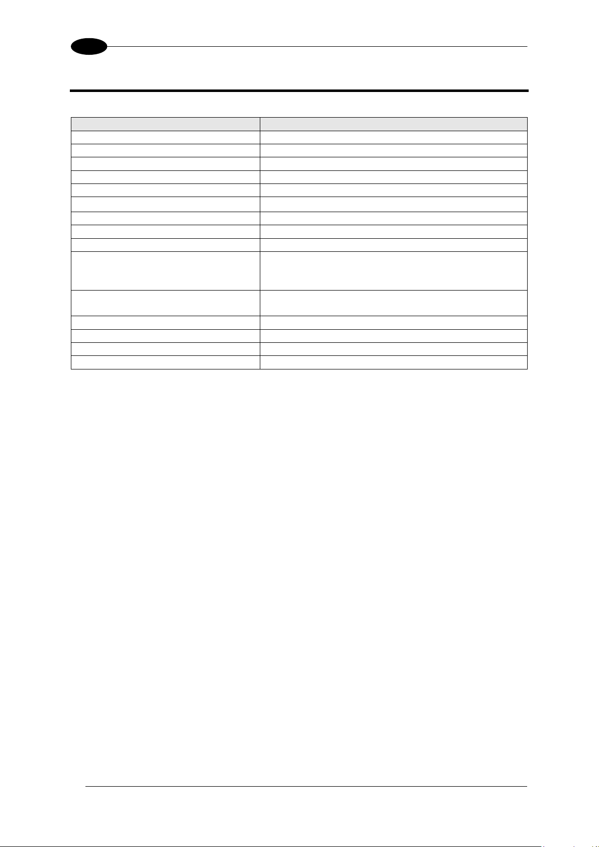
13 SPECIFICATIONS
Item
Description
Supply voltage:
24 Vdc ± 10%
Ripple voltage:
2.4 Vpp max.
Current draw:
Max 150 mA @ 24Vdc max
Dimensions:
96 x 96 x 39 mm
Indicators:
8 LEDs + 3.5'' colour LCD monitor
Setup:
DataVS2 GUI
Data retention:
Non volatile FLASH memory
Operating temperature:
-10 °C ... +55 °C
Storage temperature:
-20 °C ... +70 °C
Vibrations:
(EN60068-2-6)
14 mm @ 2 to 10 Hz;
1.5 mm @ 13 to 55 Hz;
2 g @ 70 to 200 Hz; 2 hours on each axis
Shock resistance:
(EN60068-2-27)
11 ms (30 G) 6 shocks on each axis
Housing material:
ABS
Mechanical protection:
IP20 (IP40 when panel mounted)
Connections:
2 x M12 4 poles
Weight:
180 g
DATAVS2-VSM INSTRUCTION MANUAL
Page 53
OVERALL DIMENSIONS
47
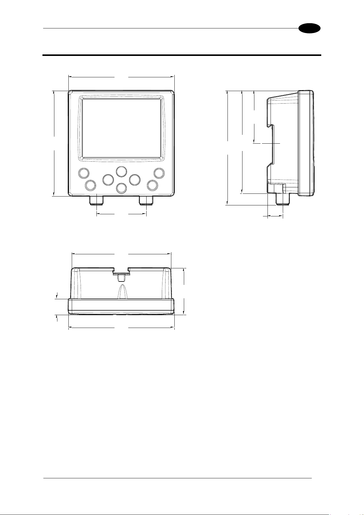
14
96
[3.78]
96
[3.78]
48.0
[1.89]
93.4
[3.68]
104
[4.09]
45.0
[1.77]
90.2
[3.55]
14.5
[0.57]
96
[3.78]
42.5
[1.67]
14.0
[0.55]
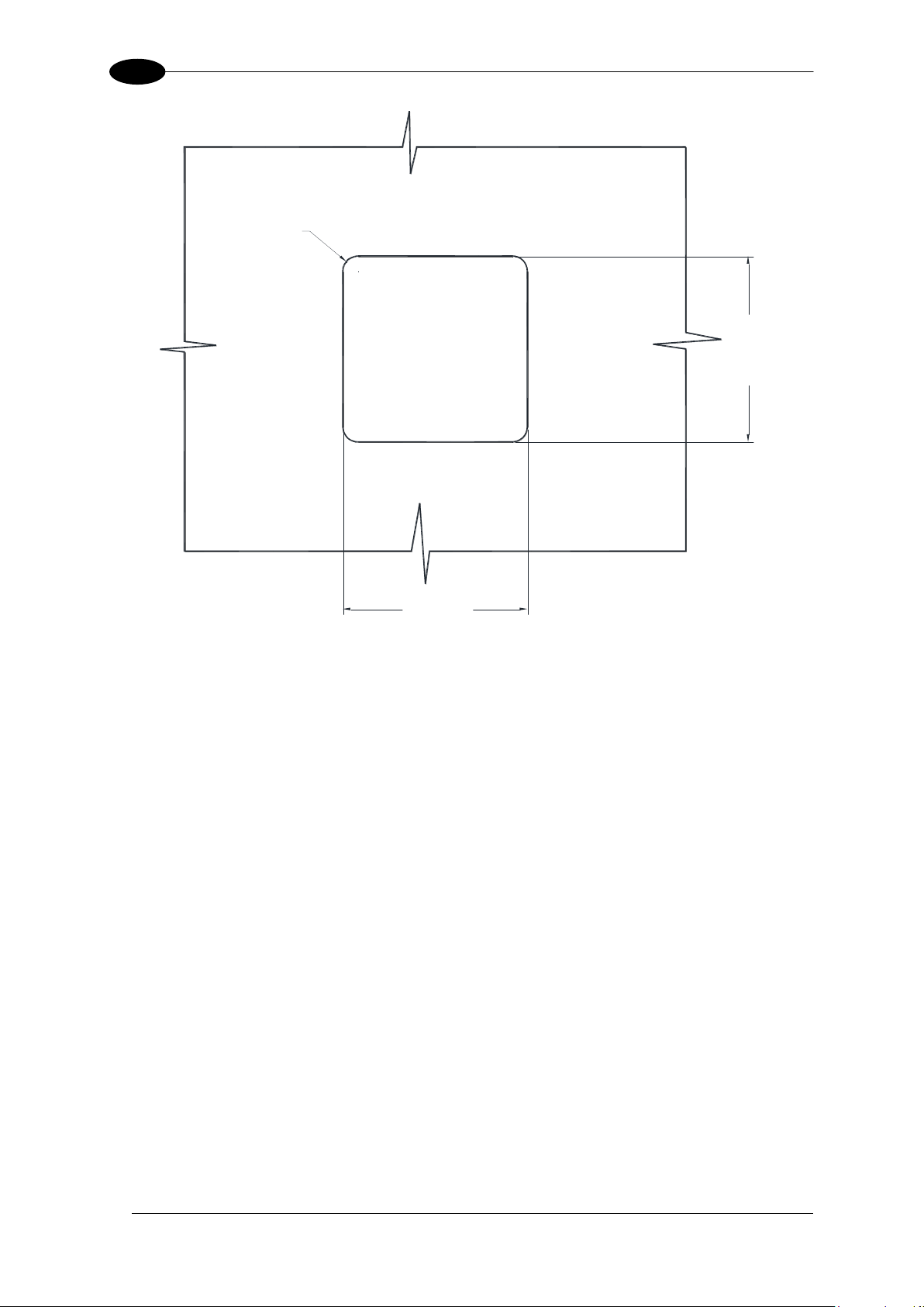
14 OVERALL DIMENSIONS
Page 54
DATAVS2-VSM INSTRUCTION MANUAL
48
14
92
±0.2
[3.62
±0.01
]
92
±0.2
[3.62
±0.01
]
R7.5
[R0.30]
Page 55

 Loading...