

Page 1
USER’S MANUAL
> VLASE
TM
UV
Page 2

ii
Datalogic S.r.l.
Via S. Vitalino 13
40012 – Calderara di Reno
Italy
VlaseTM UV User’s Manual
Ed.: 05/2017
Helpful links at www.datalogic. c om: Contact Us, Terms and Conditions, Support.
© 2014 - 2017 Datalogic S.p.A. and/or its affiliates ALL RIGHTS RESERVED. Without
limiting the rights under copyright, no part of this documentation may be reproduced,
stored in or introduced into a retrieval system, or transmitted in any form or by any means,
or for any purpose, without the express written permission of Datalogic S.p.A. and/or its
affiliates. Datalogic and the Datalogic logo are registered trademarks of Datalogic S.p.A. in
many countries, including the U.S.A. and the E.U.
Vlase, Arex, Eox, Violino, Lighter Suite are trademarks of Datalogic S.p.A. and/or affiliates.
All other trademarks and brands are property of their respective owners.
Datalogic reserves the right to make modifications and improvements without prior
notification.
Datalogic shall not be liable for technical or editorial errors or omissions contained herein,
nor for incidental or consequential damages resulting from the use of this material.
821002863 rev. C
Page 3
iii
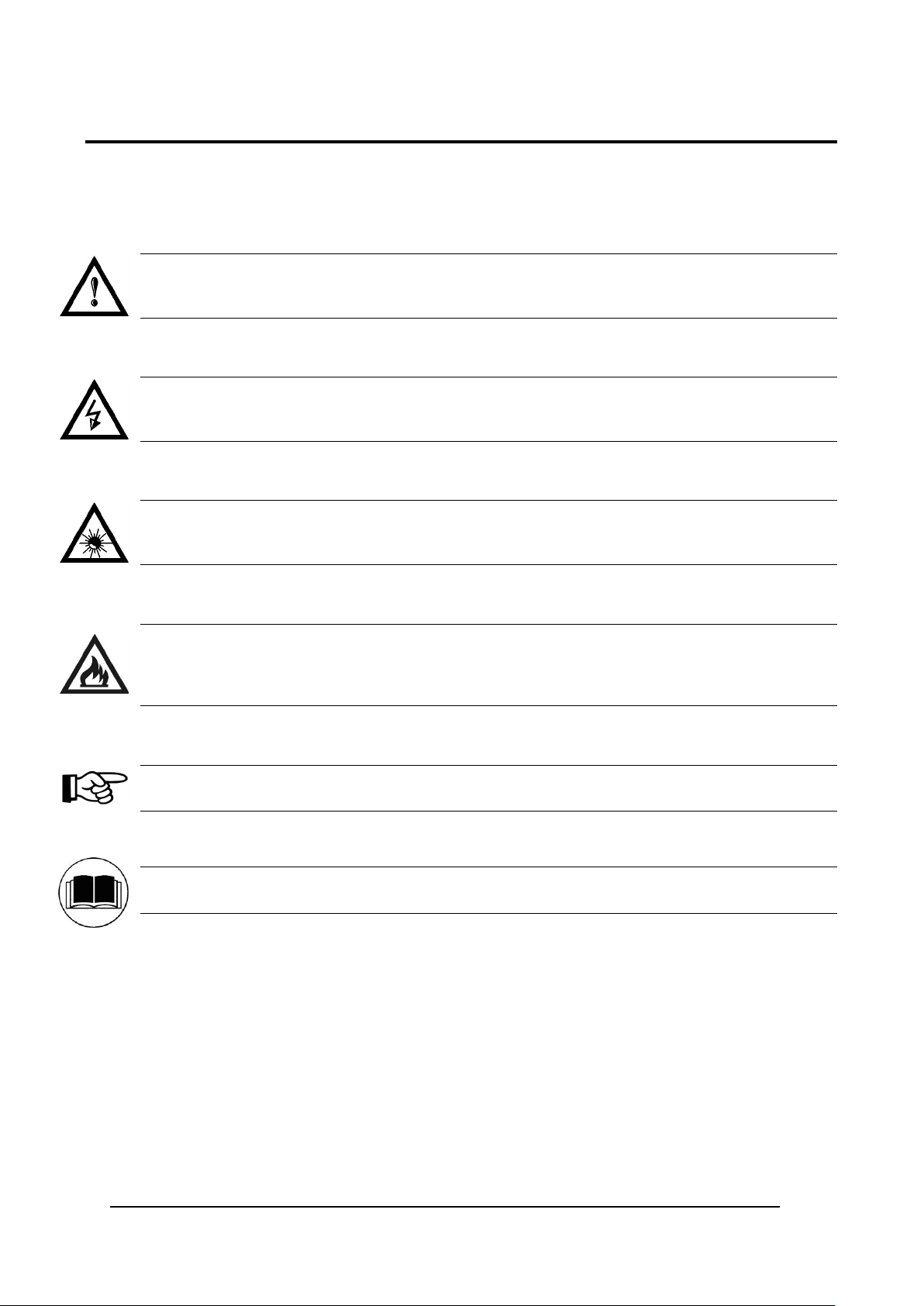
SYMBOLS
Symbols used in this m anual along with their meaning are show n below. Symbols and signs are repeated
within the chapters and/or sections and have the following meaning:
Generic Warning:
This symbol indicates the need to read the manual carefully or the necessity of an important
maneuver or maintenance operation
.
Electricity Warning:
This symbol indicates d angerous voltage associated with t he laser product, or powerful enough to
constitute an electrical risk. This symbol may also appear on the marking system at the risk area
.
Laser Warning:
This symbol indicates the danger of exposure t o visible or invisible las er radiatio n. This symbol may
also appear on the marking system at the risk area
.
Fire Warning:
This symbol indicates the d anger of a fire w hen proce ssing flam mable m aterials. Because th ere is a
danger of fire, it is indispensable to follow the instructions provided by the manufacturer when
commissioning the marking system
.
Notice:
Notes, usage tips, or additional information.
Note:
Carefully read the user’s manual before using the marking system.
Page 4
iv
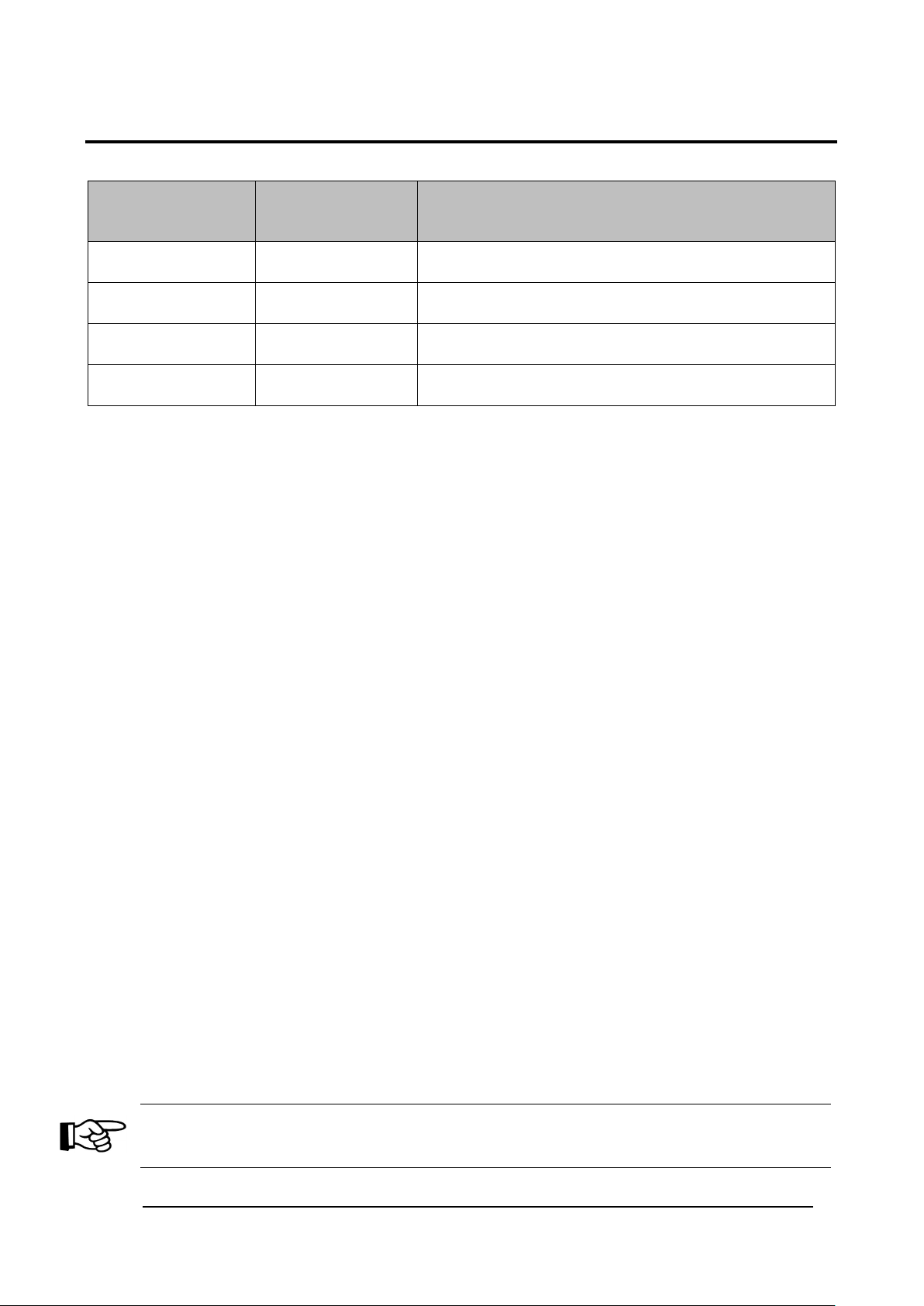
REVISION INDEX
Revision Date Number of added or edited pages
821002860 10-03-2015 Release
821002861 rev.A 15-01-2016 General Review
821002862 rev.B 29-04-2016 Appendix C
821002863 rev.C 22-05-2017 ii, Appendix F
NOTE:
We sometimes update the documentation after original publication. Therefore, you should also
review the documentation at www.datalogic.com for updates.
Page 5
v
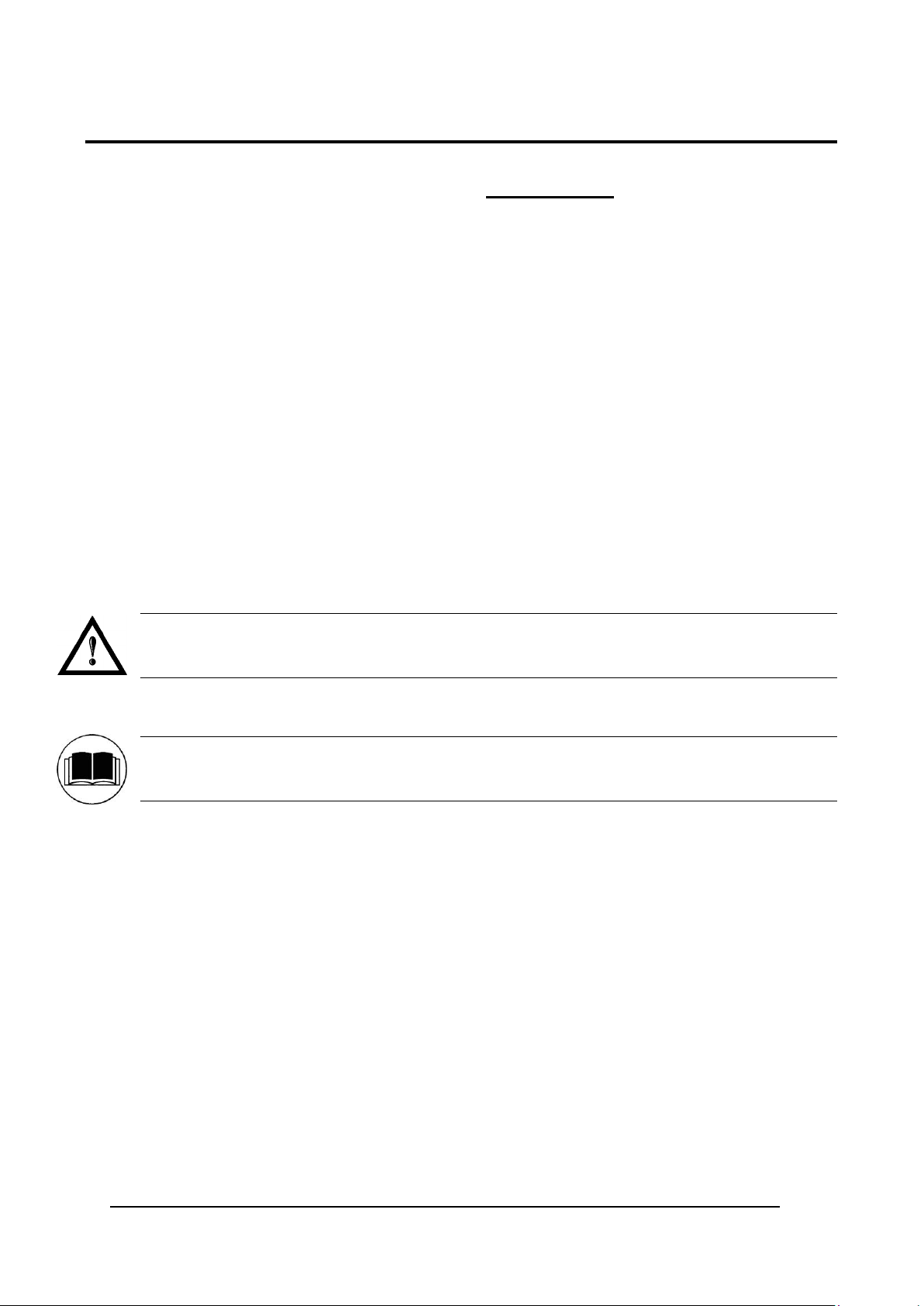
FOREWORD
Information included in this manual is intended for a qualified installer able to integrate the marking
system into a system, complying with all the protection features required by international rules and
local legislations. Refer to the Appendices for further infor m ation.
Following manual refers to an VLASETM 3PWX-TLS2 system in Class 4 configuration.
In addition to being profess ionally trained in their role, pers onnel assigned to work on the m arking system
must be informed and m ade acquainted with the risk s inherent to invisible and visib le laser radiation. The
operator is required to caref ully read the section of the m anual concerning safet y instructions as well as the
sections related to matters falling under her/his responsibility.
The workers assigned to the marking system can be identified as:
OPERATOR
•
responsible for loading elements to be processed, visually checking the work cycle, removing the
finished product and cleaning the marking system.
MAINTENANCE WORKER
•
responsible for the electrical, mechanical and optical maintenance and adjustment of the marking
system.
WARNING!
Datalogic shall not be held responsible for any non-conforming use of the marking system of its
manufacture
.
NOTE:
BEFORE INSTALLING AND USING THE MARKING SYSTEM, READ CAREFULLY THE
APPENDICES.
Page 6
vi
OVERVIEW
We are honoured b y your c hoice of a Data logic produc t, spec ificall y a new product belonging to the VlaseTM
product fam ilies, which aim to satisf y new market evolutions, and especially the integrat ion industrial laser
sources.
OPERATION OF A LASER SYSTEM WITH GALVANOMETRIC SCANNING
The laser generates a train of high-energy pulses of invisible radiation.
In order to obtain a mor e accur ate focus, t he laser beam is f irst enlarged using an optica l expans ion s ystem
and then deflected by a scanning system consisting of two mirrors mounted on galvanometric motors.
These mirrors deflect the beam in a controlled beam along the X and Y axes; processing of the product
surface occurs by coordinating the movement of the two motors with the turning on/off of the laser beam.
The deflected laser beam is focused by an F-Theta objective before it hits the surface of the product.
Generally speaking, the marking is carried out within the focus of the beam.
MARKING SOFTWARE
The marking software Lighter is preinstalled on the system.
NOTE:
Consult Lighter software user’s manual for a proper use of the same.
NOTE:
Consult the proper Appendix to upgrade the preinstalled software if necessary.
The VlaseTM laser marking system features a control unit whose size is compatible with the standard 19”
2,5U in varnished steel, a nd a resonator whose compact dimensions make it eas y to integrate into a s ystem
that comprises safet y devices required by applicab le regulations, the management of m arking signals and
the customer’s complementary modules, if any.
All laser marking system connections are found on the rear of the rack: power supply, safety, electrical
signals, communication ports, patch cord to the scanner head, while the front features key and enable
command devices, status LED in addition to a USB connector for the communication with the internal
embedded controller.
TM
Vlase
Switched” configuration.
The mechanical and electric al characteristic s satisf y standardization and connect ivity needs of the ind ustrial
field, such as the new 19” rack and different solutions for laser system control.
The new marking system control platform allows for an easy integration in industrial environments and
complies with the sta ndard of the other Dat alogic mark ing systems, with the sam e philosophy im plemented
in Arex
Based on the optical la yout of the Datalo gic Violino
improvements in term s of performances thanks to the new laser diode current and temper ature controllers,
developed by the Data logic labor atories, which short warm -up time and im prove the s tabilit y of emitted las er
power. The operating temperature range has been extended to 5°- 40°C for its use in industrial
environments.
belongs to the fam ily of DP SS (D iode Pum p Soli d Stat e) las er so urces in the “e nd pum ped” a nd “ Q-
TM
.
TM
laser sour ce, the VlaseTM fam ily guarantees sign ificant
WARNING!
Marking system installation in secure environment is responsibility of the system integrator!
Page 7
vii
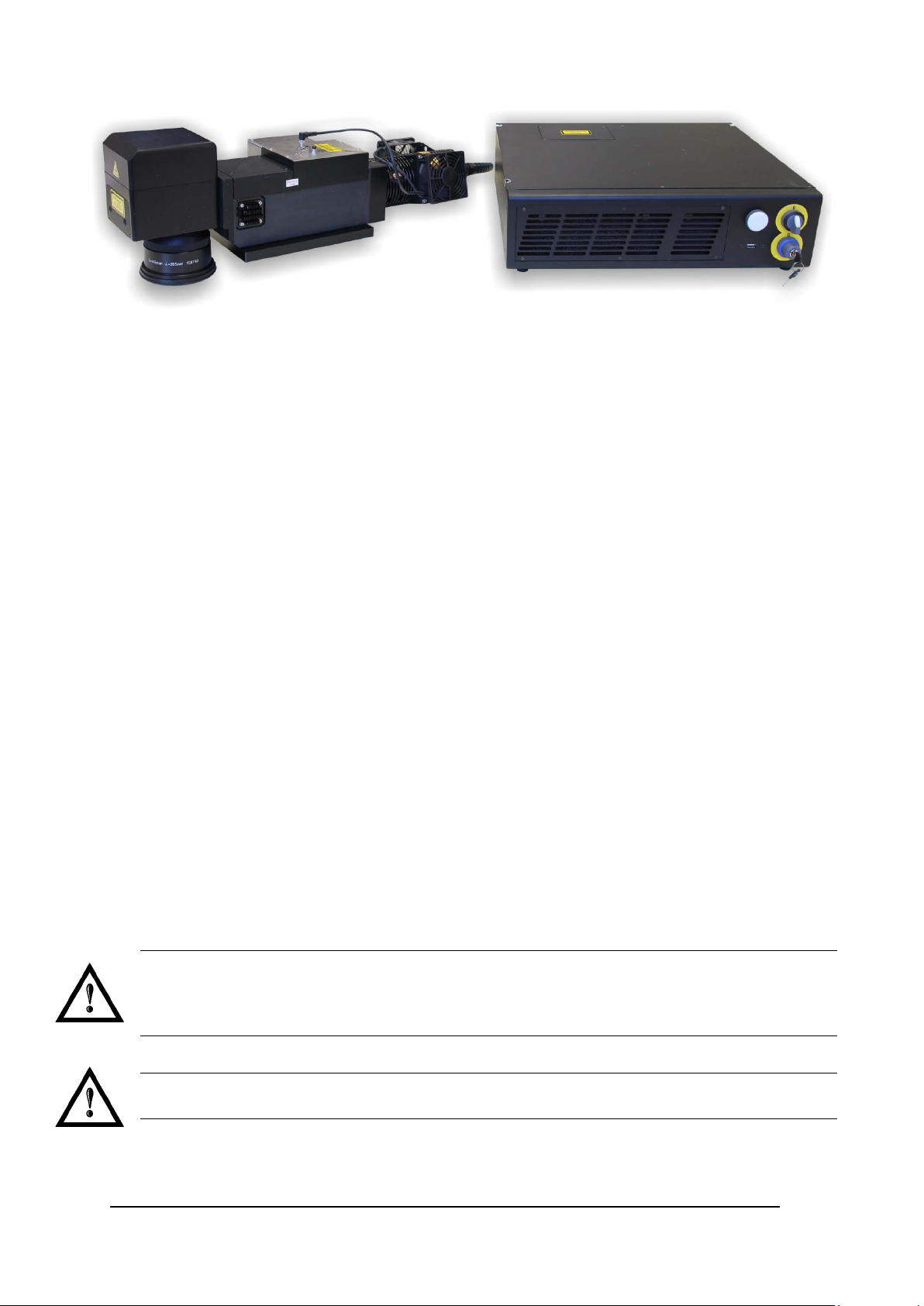
Figure 1: Control rack and resonator with scan head.
Main features:
• 100 to 240 V AC @ 50-6 0 H z Power Supply
• Operating Temperature Range extended to 40°C
• Fully integrated marking and system control
• Integrated PC embedded and marking software for stand-alone operation
• Ease of integration in industrial en vironments and m aximum control compatib ility with other m arking
platforms (Arex
• Integrated photocell and encoder connectors for Marking ON Fly (MOF) applications
• Unattended control of the system by LAN network or serial communication (RS232 protocol)
• Stable Marking process and high a beam quality (M
• Compact Design: 19” 2,5U rack
• High peak power and shor t pulse dur at io n (<10ns)
• Available cable lengths: 3m standard, other length available on request
• Simplified access to Laser Diode Module for fiber installation and Laser Diode Module maintenance
• Dedicated software tool for laser parameter setting and diagnostics
TM
/EoxTM)
2
<1.3)
IMPORTANT WARNINGS
Access to the interna l part s of the marking system is allo wed o nly to authorized pe r sonnel, du ly qualified and
trained with regards to risks of optical and electrical nature.
Datalogic declines a ny and all responsib ility for work carr ied out on live parts b y untrained or unauthor ized
personnel.
WARNING!
It is forbidden to change the intended use for which the system was designed and developed.
Datalogic declines any responsi bility and liability for irregular and im proper use of the laser system
which it manufactures.
WARNING!
These marking system actuation is demanded to the system integrator.
Page 8

viii
TABLE OF CONTENTS
SYMBOLS III
REVISION INDEX IV
FOREWORD V
OVERVIEW VI
OPERATION OF A LASER SYSTEM WITH GALVANOMETRIC SCANNING vi
MARKING SOFTWARE vi
IMPORTANT WARNINGS vii
TABLE OF CONTENTS VIII
1 CONTENTS OF THE PACKAGING 10
1.1 UNPACKING 10
1.2 MAIN HARDWARE 11
1.3 CABLES AND OTHER COMPONENTS 11
1.4 TRANSPORT 12
1.5 ON MOISTURE CONDENSATION 12
1.6 FIXING AND POSITIONING 13
1.7 INSTALLATION ENVIRONMENT 15
1.8 FUME / DUST EXTRACTOR 16
1.9 FAN INSTALLATION 16
2 TECHNICAL SPECIFICATIONS 17
2.1 TECHNICAL CHARACTERISTICS 17
2.2 DESCRIPTION OF THE MODULES 19
2.2.1 RESONATOR 19
2.2.2 CONTROL RACK 20
2.3 MARKING AREA SPEC IF I C AT I ON 21
2.4 EXTERNAL CONNECTORS SPECIFICATIONS 23
2.4.1 INTERLOCK CONNECTOR 23
2.4.2 INTERLOCK OUT CONNECTOR 25
2.4.3 COMMAND BOX CONNECTOR (LASER CONTROL) 26
2.4.4 AXES CONNECTOR (I/O CONTROL) 31
2.4.5 RS232 CONNECTOR (COM2) 32
2.4.6 ENCODER CONNECTOR 33
2.4.7 PHOTOCELL CONNECTOR 33
2.5 INPUT/OUTPUT SIGNAL SPECIFICATIONS 34
2.6 CONNECTION EXAMPLES 35
3 INSTALLATION AND SET UP 36
3.1 CONNECTIONS 36
3.1.1 CONNECTING COMMAND BOX CABLE 36
3.1.2 CONNECTING INTERLOCK CABLE 37
3.1.3 CONNECTING INTERLOCK OUT CONNECTOR 37
3.1.4 CONNECTING THE OPTICAL FIBER TO THE CONTROL RACK 38
3.1.5 CONNECTING THE OPTICAL FIBER ON THE RESONATOR 41
3.1.6 CONNECTING RADIOFREQUENCY CABLE 43
3.1.7 CONNECTING MDR CABLE 44
3.1.8 CONNECTING RESONATOR CABLE 45
3.1.9 CONNECTING FAN CABLE 46
3.1.10 CONNECTING POWER SUPPLY CABLE 47
3.1.11 GROUND CONNECTION 47
3.1.12 CONNECTING RESONATOR POWER SUPPLY CABLE 48
3.1.13 LOCAL MODE CONNECTION 49
3.1.14 REMOTE MODE CONNECTION 50
3.1.15 F-THETA LENS PROTECTION CAP REMOVAL 51
4 USE AND OPERATION 52
4.1 TURNING ON SEQUENCE 52
Page 9

ix
4.1.1 ADVICE ON USING THE SYSTEM 55
4.2 LOCAL MODE OPERATIONS 56
4.3 REMOTE MODE OPERATIONS 56
4.4 OPERATING IN LOCAL MODE 58
4.4.1 HOW TO CREATE AND EDIT YOUR FIRST GRAPHIC DOCUMENT 59
4.4.2 HOW TO TEST AND ENGRAVE YOUR DOCUMENT 62
4.4.3 HOW TO USE EXTERNAL SIGNALS TO ENGRAVE YOUR DOCUMENT 64
4.5 THERMALIZATION AND SUPPRESSION OF GIANT PULSES 66
5 CUSTOMIZE THE SYSTEM’S SOFTWARE 68
5.1 CHANGE O.S. LANGUAGE AND KEYBOARD LAYOUT 68
5.2 CHANGE LAN CONFIGURATION AND IP ADDRESS 71
5.3 CHANGE VIDEO SETTING 74
5.4 REMOTE DESKTOP CONNECTION 76
6 ACCESSORIES 78
6.1 CONTROL BOX 78
6.2 MARKING ON FLY KIT 79
6.3 CABLE KIT LENGTH PLUS 79
6.4 RACK HANDLES 80
7 TECHNICAL SUPPORT 81
7.1 SEALS 81
7.2 MAINTENANCE 82
7.2.1 F-THETA SCAN LENS CLEANING PROCEDURE 82
7.2.2 AIR FILTER CLEANING PROCEDURE 83
7.3 PRODUCT SUPPORT AND CUSTOMER SERVICE 84
APPENDIX A: LABELS IDENTIFICATION 85
POSITIONING OF EXTERNAL LABELS 87
APPENDIX B: STANDARDS 89
LASER STANDARDS 89
CE COMPLIANCE 89
FCC COMPLIANCE 89
APPENDIX C: SAFETY CONSIDER ATION ACCORDING TO EN ISO 13489-1:2008 90
PERFORMANCE LEVEL (PL) 90
APPLICATION EXAMPLE 90
SAFETY FUNCTIONS OF VLASE
APPENDIX D: NOTE ABOUT LASER 95
LASER SAFET Y 95
LASER RADIATIO N 96
ABSORPTION OF LASER RADIATION 97
CLASSIFICATION AND DANGER LEVEL 97
RADIATION VIEWING CONDITIONS 98
DIRECT VIEWING OF THE LASER BEAM 98
DIRECT VIEWING OF THE BEAM AFTER MIRROR REFLECTION 98
DIRECT VIEWING OF THE BEAM OUTPUT BY AN OPTICAL FIBER 98
DIRECT VIEWING OF THE BEAM AFTER FOCUSING 98
SCATTERED VIEWING OF THE BEAM AFTER FOCUSING 98
N.O.H.D. DETERMINATION AND O.D. OF PROTECTION GOGGLES 99
EYES AND SKIN RISKS 101
GENERAL SAFETY REGULATIONS 101
COLLATERAL RISKS 101
TM
94
APPENDIX E: SOFTWARE UPGRADE 103
APPENDIX F: RECOVER THE SYSTEM USING USB RECOVERY DISK 106
APPENDIX G: MECHANICAL DRAWINGS 112
FIGURES 114
Page 10

10
1 CONTENTS OF THE PACKAGING
1.1 UNPACKING
When unpacking the marking system from the shipping carton you should:
• Remove the documentation from the top of the marking system
• Remove the box containing the accessories
• Carefully remove the marking system from the packaging using both hands
VLASETM UV
Figure 2: Unpacking.
Before installing or operating the marking system, you should:
• Inspect the shipping container for damage
• Inspect the marking system for signs of damage
• Confirm that the shipping carton contains all items on the shipping inventory list including any
accessories
Retain all packaging m aterials until the marking syste m has been inspect ed for complete ness and damage ,
and you have checked the operating performance. If anything is missing or defective, see chapter 7 for
contact details.
Page 11
CONTENTS OF THE PACKING
11
Interlock cable
Safety Key
USB Stick
Cable gland
Rack adapters
Sample Test
User Manual
Test Report
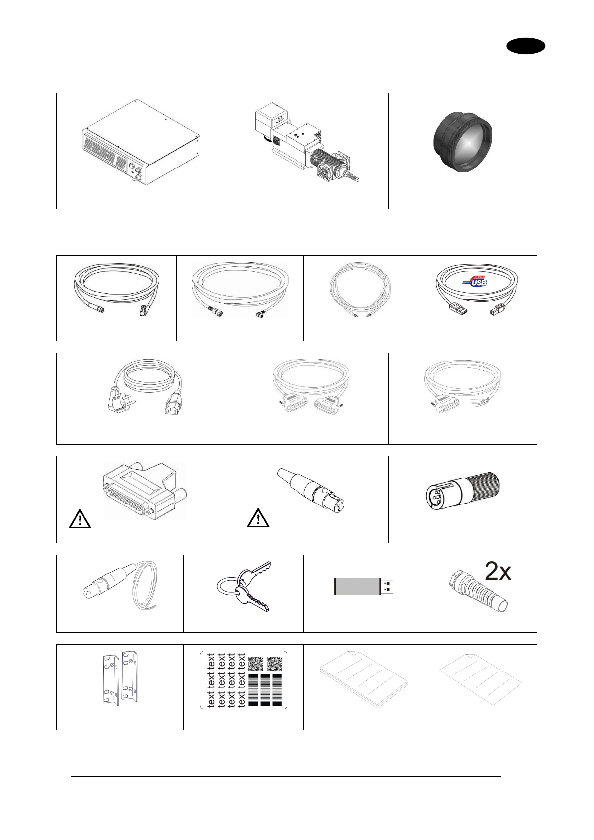
1.2 MAIN HARDWARE
Control rack Resonator F-Theta (except 3PWX-T0SV)
1.3 CABLES AND OTHE R CO MP O NE NTS
RF cable Resonator cable Optical fiber cable USB cable
Power supply cables Scan Head cable Command Box cable
Command Box Gold connector (*) Interlock connector gold (*) Interlock OUT connector
* If this connector is used, the marking system works in DANGEROUS condition (MUTING DEVICE).
Page 12
VLASETM UV
12
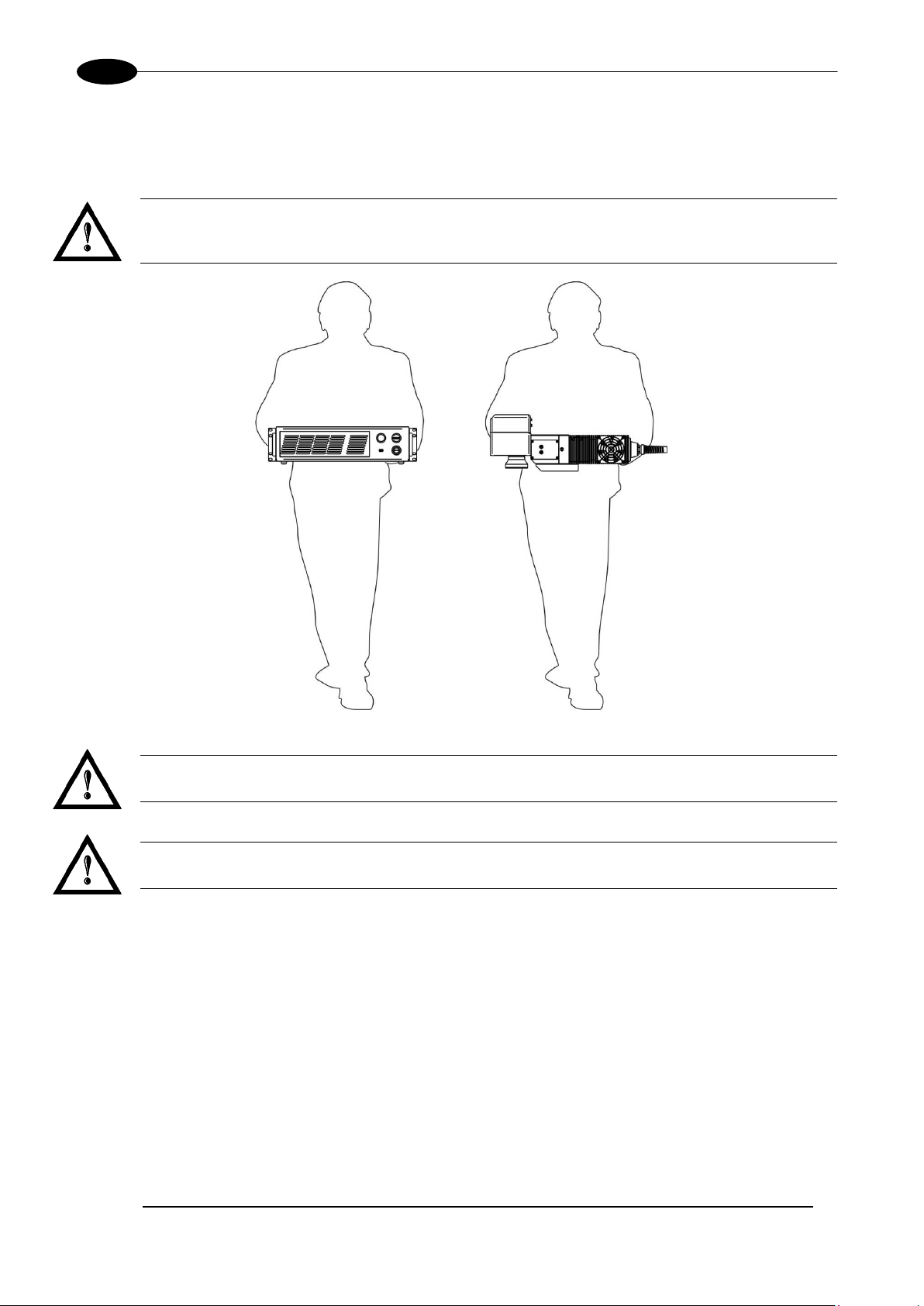
1.4 TRANSPORT
The marking system needs to be moved in order to proceed to its positioning and wiring. The marking
system can’t be lifted up and moved by a single person.
WARNING!
To avoid damaging or breaking the optical fiber, n ever subject it a bending radi us below the limits
specified in the technical specification table.
Figure 3: Transport.
WARNING!
VlaseTM is a delicate optical laser marking system, avoid damaging it with shock and vibrations.
WARNING!
Be extremely careful to not damage the fiber optic cable between resonator and rack.
1.5 ON MOISTURE CONDENSATION
If the marking s ystem is brought directl y from a cold to a warm loc ation, moisture may condens e inside or
outside the marking system. This moisture condensation may cause a malfunction of the marking system.
If moisture condensation occurs
Turn off the marking system and wait about 1 hour for the moisture to evaporate.
Note on moisture condensation
Moisture may condens e when you bring the m arking system from a cold place int o a warm place (or vice
versa) or when you use the marking system in a humid place as shown below.
How to avoid moisture condensation
When you bring the mark ing system from a cold place into a war m place, put it in a plastic bag and s eal it
tightly. Remove the bag when the air temperature inside the plastic bag has reached the ambient
temperature (after about 1 hour).
Page 13
CONTENTS OF THE PACKING
13
1.6 FIXING AND POSITIONING
The marking system must be positioned in a safely manner and the precautions listed below must be
followed.
Figure 4: Positioning rack.
Figure 5: Vertical positioning (need additional fixing).
WARNING!
DO NOT fix the marking system in manner not shown in figure.
Page 14
VLASETM UV
14
The marking system can be f itted inside a special rac k cabinet equippe d with special suppor t shoulders and
handles, available on reques t. The figure below shows the mounting points for mounting in rack:
Figure 6: Fixing points on rack handles (cabinet assembly).
The resonator mus t be secured to a special base (not supplied by Datalogic ) using the four M6 threaded
holes.
The resonator, just lik e the control r ack , mus t be safety posit ioned and secur ed o n a spec ial surf ace, par allel
to the ground and absolutely vibration-free. The resonator can be secured both horizontally and vertically.
NOTE:
In order to prevent mar king distortions, install a vibrom eter on the base of the piece to be mark ed
and check for the absence of vibrations during the marking process.
NOTE:
It is recommended to install the resonator on a micrometer positioning Z-axis system!
Figure 7: Resonator fixing points
WARNING!
It is very important to s ecure the laser system before you start m arking the piece since improper
securing or positioning may cause serious damage.
Do not secure the marking system in a way other than the one described in the figure.
Page 15
CONTENTS OF THE PACKING
15
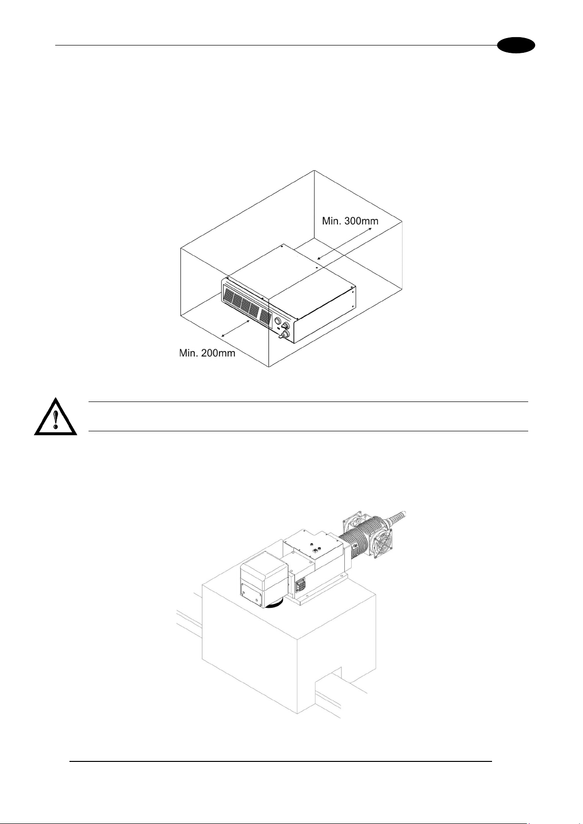
1.7 INS TALLATION ENVIRONMENT
The control rack must be installed in a s uitable environment in order to al low proper air flow passage and
correct housing of the cables.
TM
Vlase
the system. Install must not slow or stop the flow of air cooling. Moreover, do not install a heat source near.
Clean air f ilter w hen it is d ir ty. If the air f ilter is dirt y, the air-flow might bec ome not sufficient to ensure correct
cooling and might stop marking operation. Clean or exchange air filter periodically.
is an air cooled marking system: an ade quate air flow is n ecessary to guar antee correct cool ing of
Figure 8: Rack installation environmen t.
WARNING!
DO NOT place heavy objects on top of rack!
In order to have the marking system operating in safety mode (see Appendices for more details) we
recommended to ins tall the mark ing system as shown in figure below in order to limit laser ou tput area. To
obtain a good marking quality, and not to decrease life time, we recommended a ventilation or vacuum
system in a protection box to limit dust due to marking phase.
Figure 9: Safety mode example.
Page 16

VLASETM UV
16
1.8 FUME / DUST EXTRACTO R
During marking proc ess, dust and/or gas may be produc ed. It is important to use adequa te fume extractor
and/or air filtration.
WARNING!
Marking PVC (or oth er plastic m aterial) can c ause the release of chlor ine gas witc h can be harmful
to the laser operator and t o the marking system itself. Always use adequate fume extractor dur ing
PVC and plastic marking.
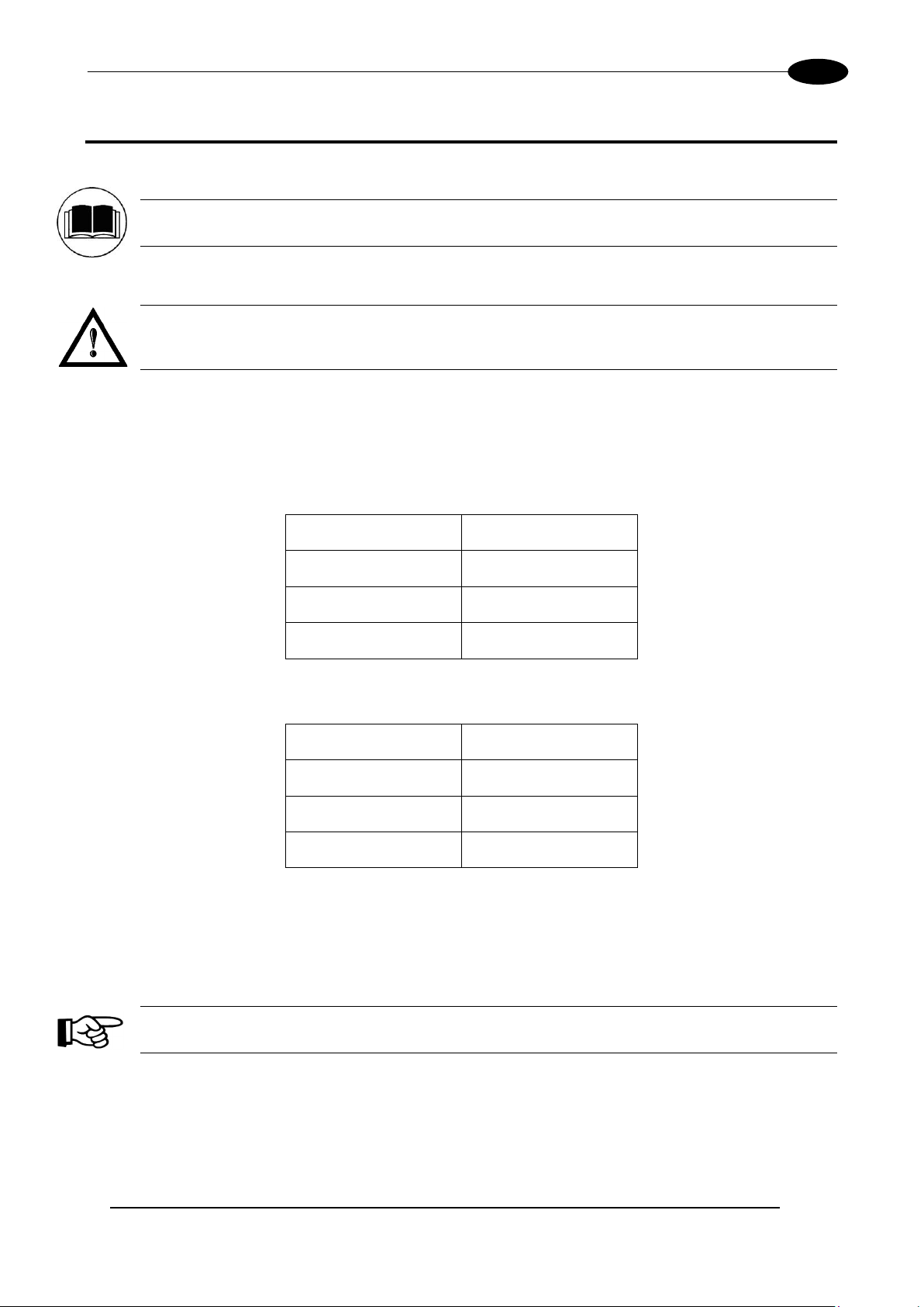
1.9 FAN INSTALLATION
The fan supplied with the d ev ice must be accurately positi one d an d f ix ed on th e res onat or s o that i t can work
properly.
The fan must be as sembled so that the air flow is aimed at the unit containing the crystal (gold-coloured
section on the resonator).
Figure 10: Fan installation.
Page 17
TECHNICAL SPECIFICATIONS
17
2 TECHNICAL SPECIFICATIONS
NOTE:
BEFORE INSTALLING AND USING THE LASER, RE AD CAREFULLY THE APPENDICES.
WARNING!
VlaseTM is a CLAS S 4 LASER PRODUCT and it is the responsibility of the OEM/system integrator to
provide the safety completeness to be ready-to-use.
2.1 TECHNICAL CHARACTERISTICS
CONTROL RACK MECHANICAL CHARACTERISTICS
RESONATOR WITH SCANNER HEAD MECHANICAL CHARACTERISTICS
(*) Without F-Theta.
(**) Vary from models.
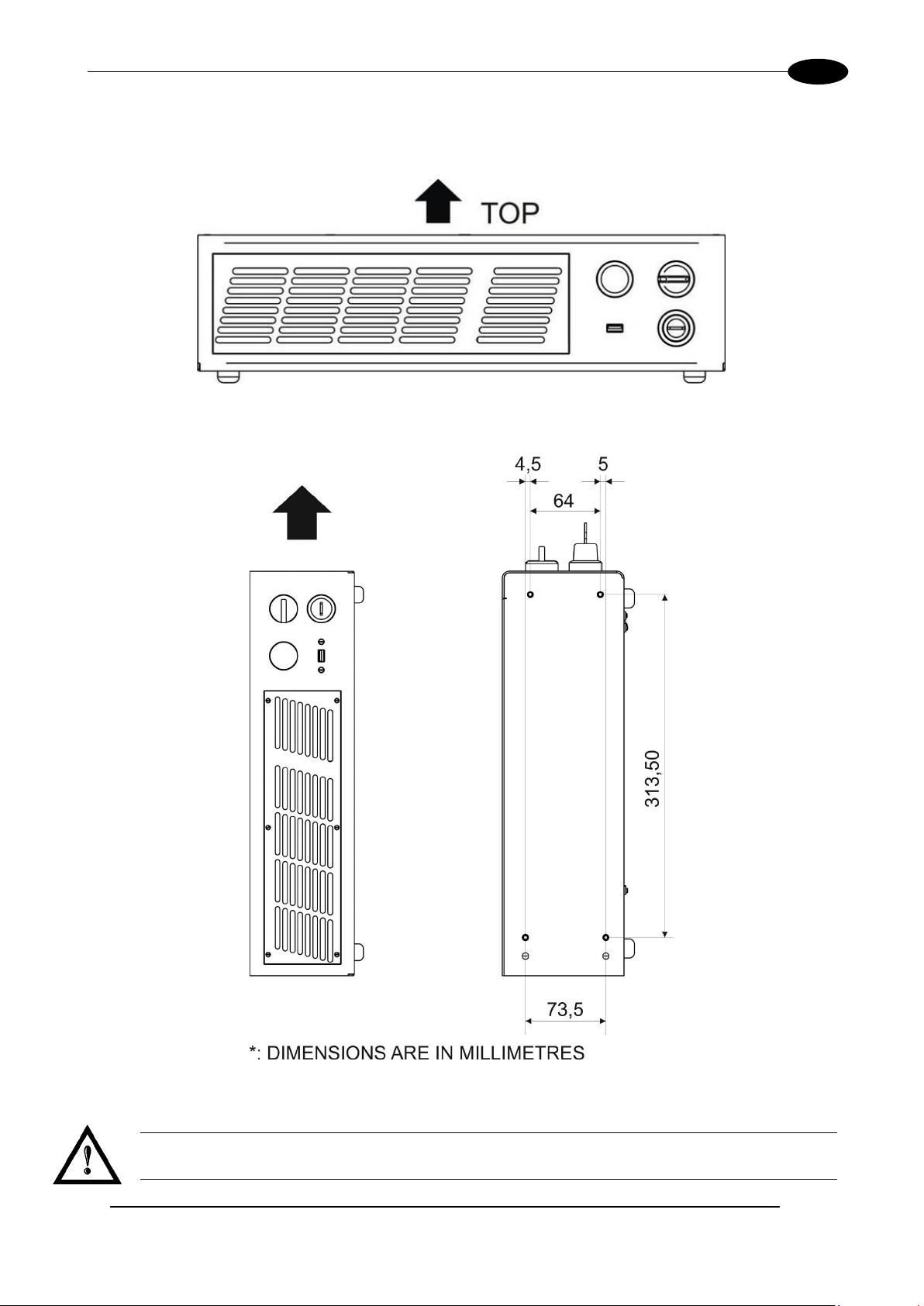
Weight 15 Kg
Height 122 mm
Width 430 mm
Depth 480 mm
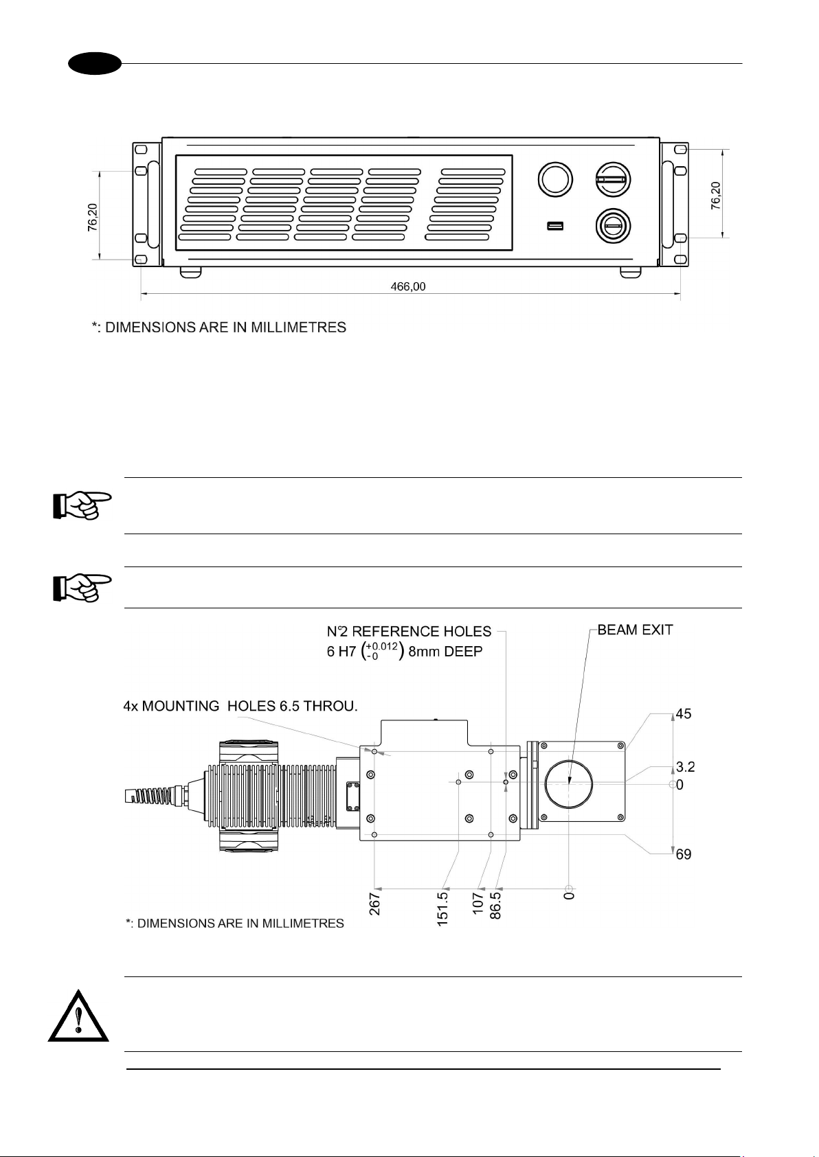
Weight (*) 11 Kg
Height 168 mm
Width 181 mm
Depth (**) 686 mm
NOTE:
Refer to Datalogic’s website for detailed drawings.
Page 18
18
Storage temperature
-10° to 60°C (14° to 140°F)
Package Drop Test
60 cm
Environmental temperature
5°C to 40°C (41° to 104°F)
Humidity
< 90% without condensation
Altitude
< 2000 m
Pollution Degree
2
Overvoltage Categor y
II
Input Voltage
100 to 240 V AC @ 50-60 Hz
Max Power
600W
LASER MARKER SOURCE (specification @ 25°C)
Laser Type
Class 4 DPSSL (Diode Pumped Solid State Laser)
Average Power at reference
Rep Rate (30kHz)1
Pulse energy (max)
mJ
0.10 (7ns)
Peak power (max)
kW
14
Central emission wavelength
nm
355
Repetition Rate2
kHz
20 ÷ 80
Laser aiming beam Class 2 <1mW @ 630-670nm
Forced Air
Resonator Fan = L10 @ 40°C : 70000h
OTHER
Optical Fiber Minimum
Bending Radius
Available Cables Length
m
3 standard, other available
Marking Speed
mm/s
Up to 3000 mm/s
3
MOF (Marking on the fly)
YES [constant speed or encoder]
Line speed – Productivity
4
Up to 75 m/min – 3 Pcs/s
Communication
RS232, Ethernet (TCP/IP 10, 100 Mbit), digital I/O
STORAGE AND TRASPORTATION CONDITIONS
Shock and vibrations MIL 810E “CAT 1 Basic Transportation”
WARNING!
This product includes precision optical parts; avoid vibration and shocks: marking quality may deteriorate.
ENVIRONMENTAL OPERATING CONDITIONS
ELECTRICAL POWER SUPPLY
VLASETM UV
Input Current 6 max
PERFORMANCES
W 3.0
Cooling
Noise dB(A) < 70 at 1 meter
mm 200 (fixed installation)
Rack Fans = L10 @ 40°C : 60000h
Char Marking Speed
char/s Up to 340 char/s
Marking Control and Software EMC Embedded Control and Lighter Suite
1
Without F-Theta
2
Without Power derating
3
h char=1mm in roman s Level100% f=30kHz F-Theta160L on TESA label
4
Single line string, Roman-s font
Page 19
TECHNICAL SPECIFICATIONS
19
2.2 DESCRIPTION OF THE MODULES
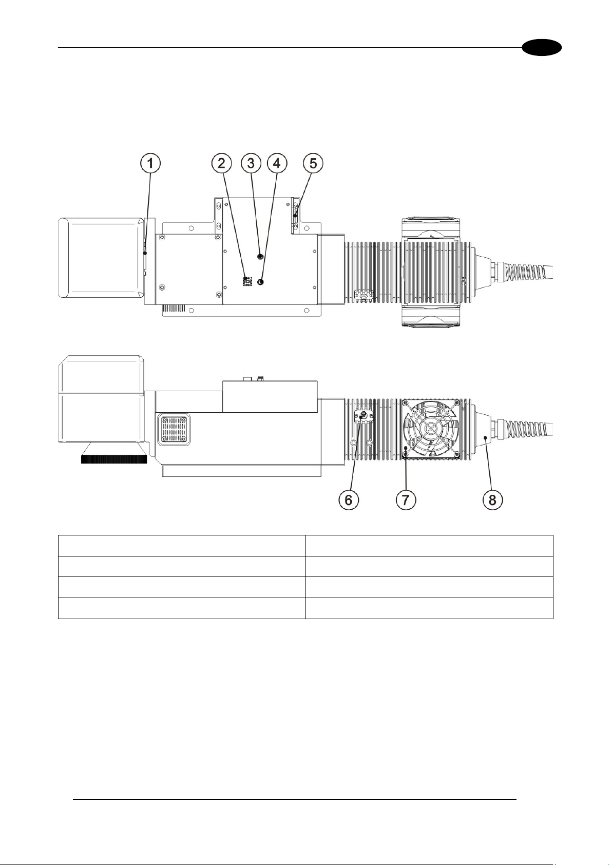
2.2.1 RESONATOR
A description of the main parts of the resonator unit is provided here below:
1) Scan Head signals connector
2) USB port type B 6) RF connector
3) Fan connector 7) Cooling fan
4) Rack-Resonator connector 8) Optic fiber inlet
5) Resonator power supply connection
Figure 11: Resonator view.
Page 20
VLASETM UV
20
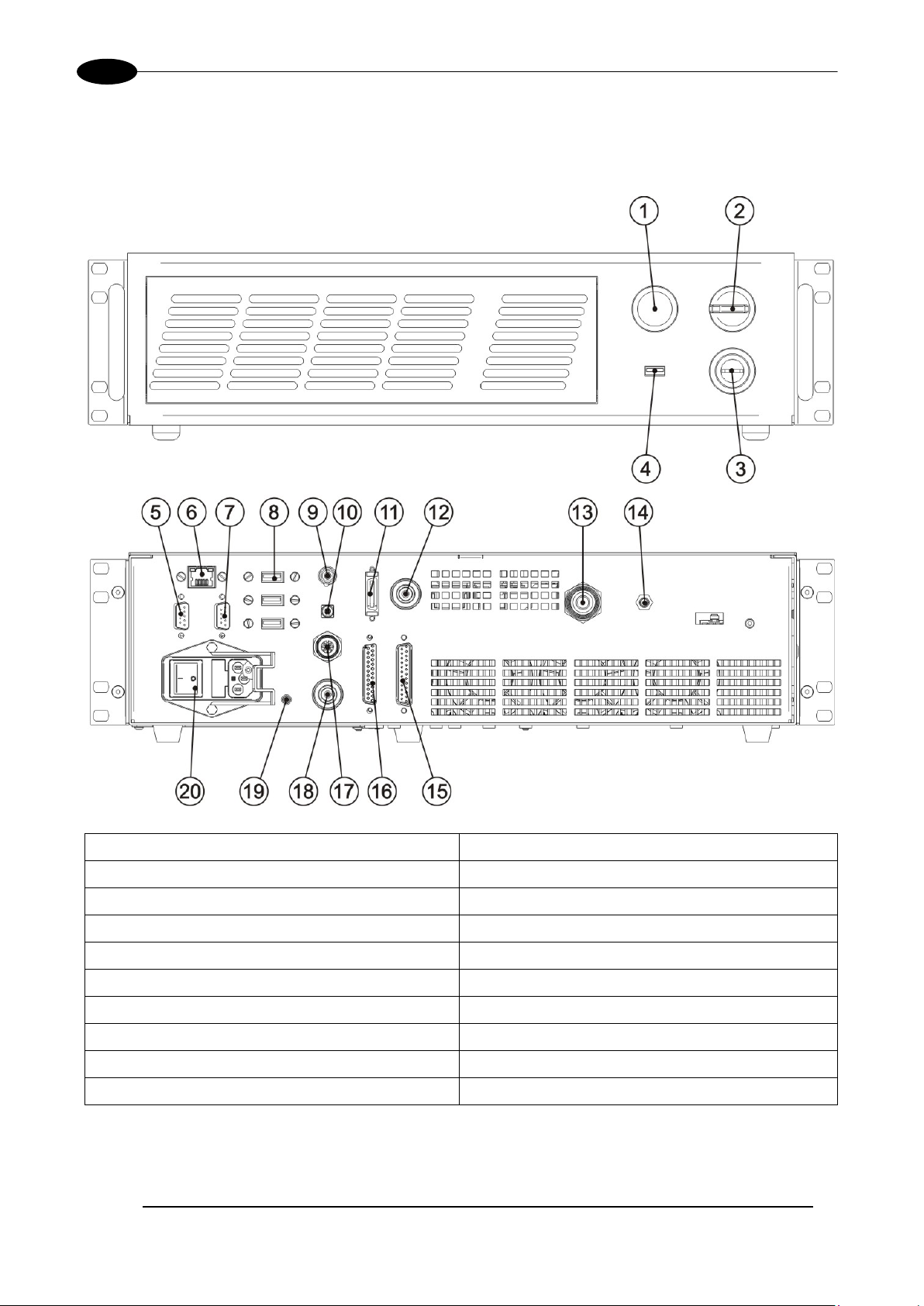
2.2.2 CONTROL RACK
A description of the c ontrol rack is provided her e below for th e purpose of obtaining the right inform ation for
proper installation of the marking system.
1) Status LED 11) MDR connector
2) Enable 12) Resonator signals connector
3) Key 13) Optic fiber outlet
4) USB port 14) RF connector
5) VGA port 15) Command Box connector
6) LAN port 16) I/O connector (axis control)
7) RS232 port 17) Photocell connector
8) 3x USB ports 18) Encoder connector
9) Interlock connector 19) Earth ground
10) Interlock OUT connector 20) Mains power supply connection
Figure 12: Control rack front view.
Page 21

TECHNICAL SPECIFICATIONS
21
ƒ
ƒ
2.3 MARKING AREA SPECIFICATION
Datalogic provides a wide range of F-Theta sc an lenses to be attached to the scannin g head to focus the
laser beam in flat Marking Field, in order to achieve high-resolution marking results.
These F-Theta scan lenses are available t o best-match the object (i.e.: logo; string; 2D m atrix; etc.) to be
marked and fit the s tandard Datalogic Scanning Head; f urther solutions about differ ent models of F-Theta
scan lenses and scanning heads will be considered upon request.
The table below lists the standard F-Theta scan lenses currently availabl e:
F-Theta Scan Lens diameter: M85
F-Theta Scan Lens
Working Distance mm 135 ± 3 197 ± 3
Fixing Distanc e mm 159 ± 4 187 ± 4
Marking Area mm
2
= 103L Telecentric
60 x 60
= 160L
110 x 110
NOTE:
Definition of Marking Area: square marking field measured on black anodized aluminium plate.
WARNING!
This product was d esigned to use only certain conf igurations of F-Theta lens and mark ing field. If
your needs are not satisfied by current available F-Theta lens configurations please contact
Datalogic for a solution. T he use of other F-T heta lenses or operation o utside the specif ied marking
field for a certain F-Theta l ens configuration can lea d to damage of F-Theta lens, scanning head or
laser source. Such damage is not covered by warranty!
WARNING!
For each F-T heta lens configurat ion Datalogic recommends the use of certain ad apter. This adapter
ensures that residual back ref lections cause d by F-T heta lens do not dam age optics of the scanni ng
head. The removal of such adapter or its incorrect use (for example incomplete thread ing, use of
another F-Theta lens adapt er, etc.) can lead to dam age of the F-Theta lens, scannin g head or las er
source. Such damage is not covered by warranty!
Page 22
22
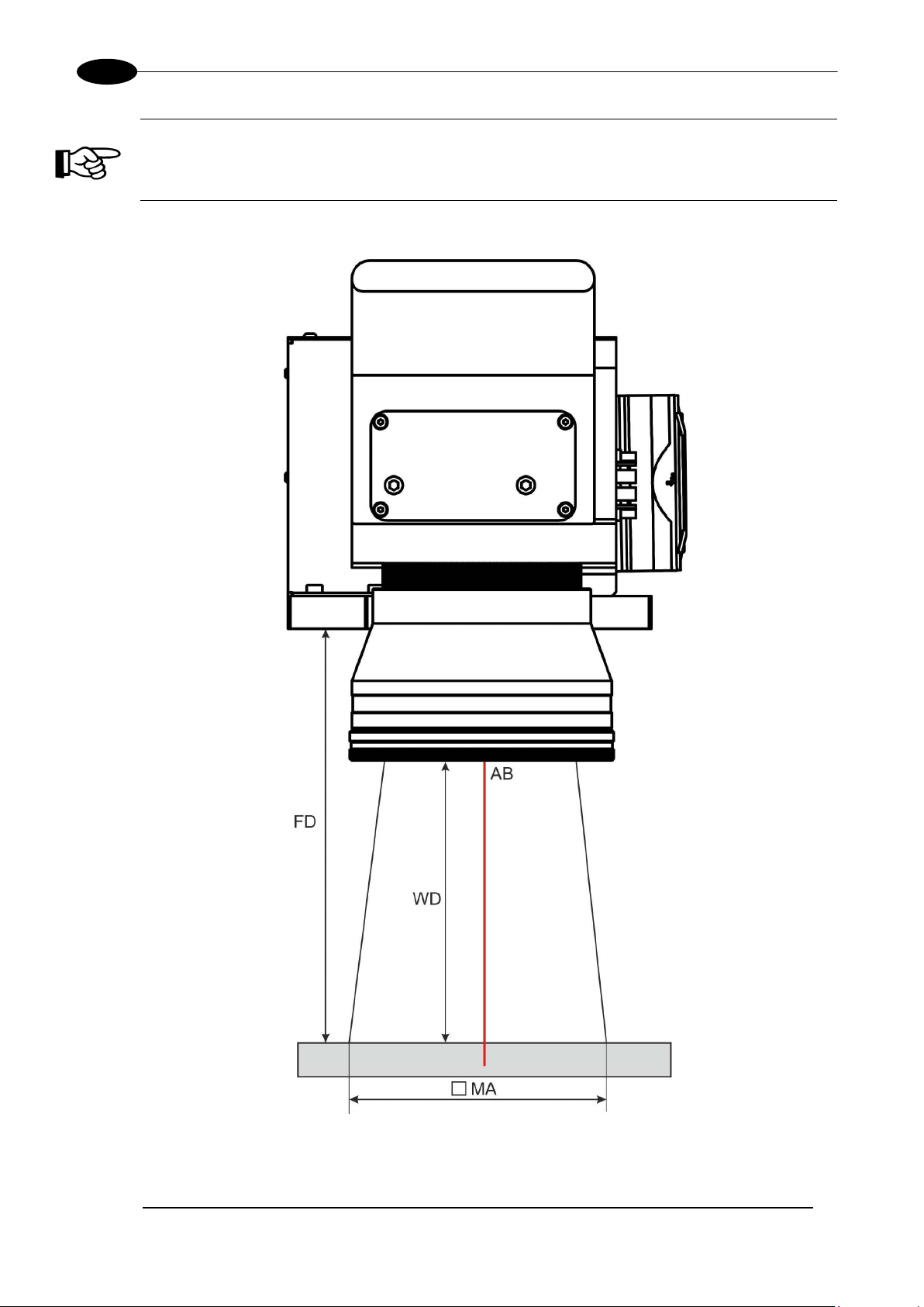
NOTE:
Working Distance is defin ed as the distance between the center of the marking area (defined
in the focal plane) and the last mechanical edge of the F-Theta Scan Lens. Refer to the
following figure.
WD: Working Distance
MA: Marking Area
AB: Aiming beam
FD: Fixing Distance
VLASETM UV
Figure 13: Marking area
Page 23
TECHNICAL SPECIFICATIONS
23
2.4 EXTERNAL CONNECTORS SPECIFICATIONS
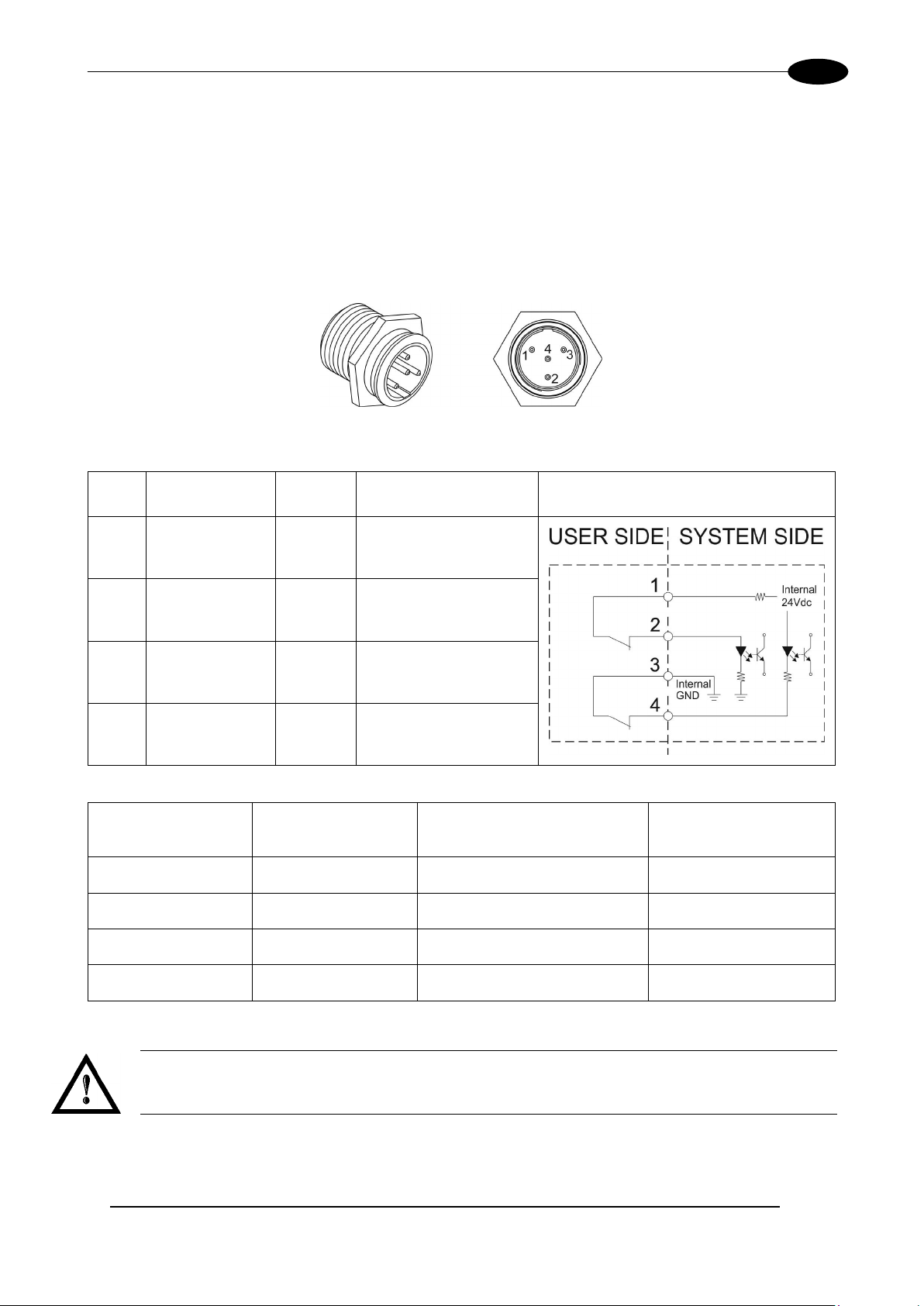
2.4.1 INTERLOCK CONNECTOR
Interlock disables the Class 4 laser source inside the marking system. Interlock internal circuit is designed to
comply with the single fault conditio n.
PANEL CONNECTOR
Type SWITCHCRAFT TB Series male Tini Q-G (Mini XLR) panel mount connector, 4 positions.
Figure 14: Male panel plug cod. TB4M (front view).
PIN SIGNAL TYPE DESCRIPTION FUNCTIONAL DIAGRAM
1 VCC_INT_IN_A OUTPUT
2 INTERLOCK_A INPUT
3 GND_INT_IN_B GND
4 INTERLOCK _B INPUT
PIN 1- PIN 2 PIN 3- PIN 4
CONTACT OPEN CONTACT OPEN NOT POSSIBLE SAFE
CONTACT CLOSED CONTACT OPEN NOT POSSIBLE DANGEROUS
CONTACT OPEN CONTACT CLOSED NOT POSSIBLE DANGEROUS
CONTACT CLOSED CONTACT CLOSED POSSIBLE DANGEROUS
24V DC reference for
INTERLOCK_A signal
INTERLOCK_A signal
Ground reference for
INTERLOCK_B signal
INTERLOCK_B signal
MARKING
FUNCTIONALITY
CONDITION
WARNING!
In order to NO T D AM AG E the i nterlock circuitr y, we recommended us ing “dry circuit” (zero vo ltage)
switches or relay circuitry.
Page 24
VLASETM UV
24
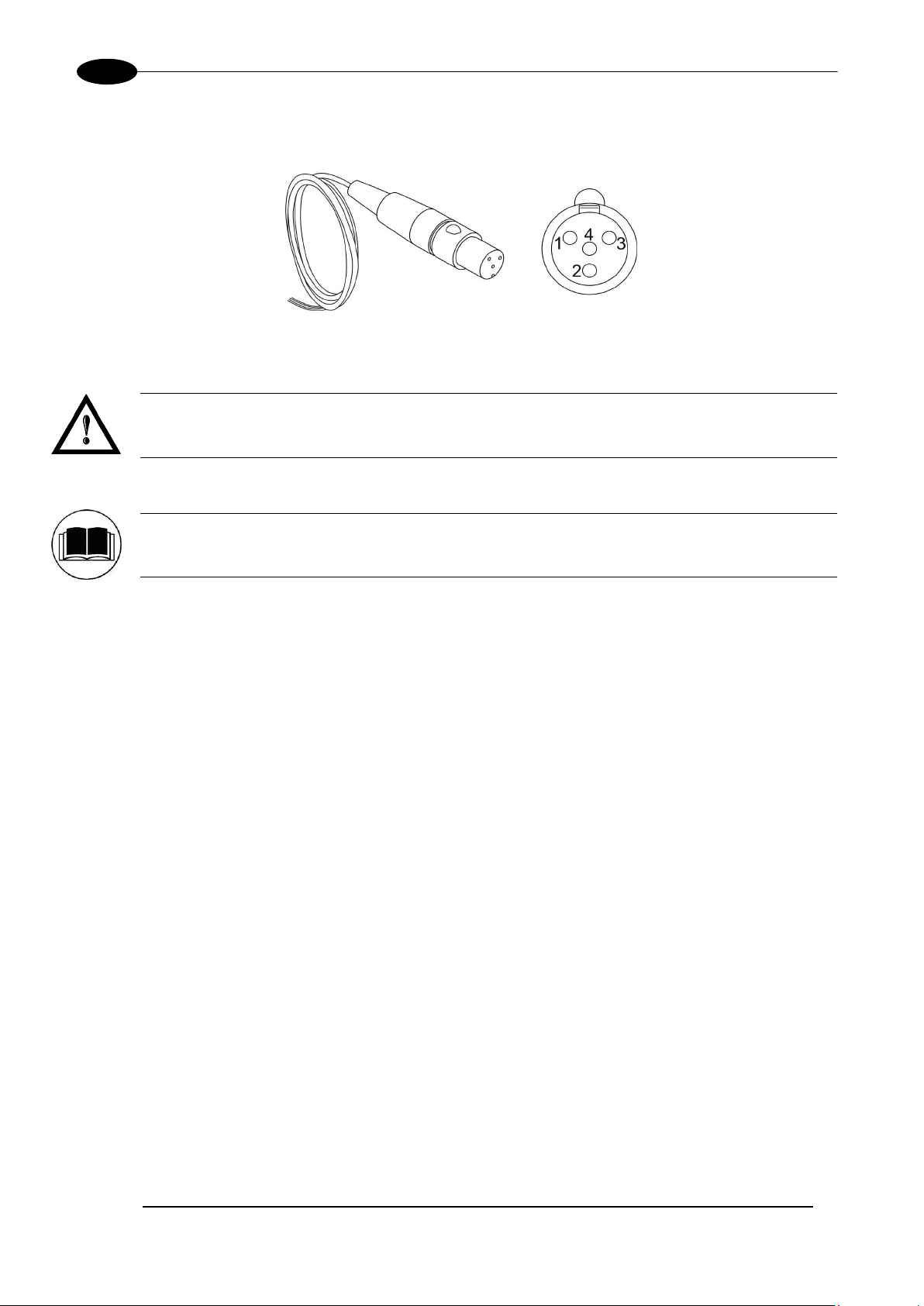
PLUG CONNECTOR
Connector type SWITCHCRAFT TA Series Tini Q-G (Mini XLR) female cable mount connectors, 4 positions.
Figure 15: Female cable mount connector cod. TY4F (solder view).
WARNING!
If the interlock gold connec tor is used, the marking s ystem is in DANGEROUS condition ( MUTING
DEVICE).
NOTE:
To restore the mark ing system it is necess ary to repeat the “ Turning on sequenc e” without shutting
down the system. See chapter 4.1 for more details.
Page 25
TECHNICAL SPECIFICATIONS
25
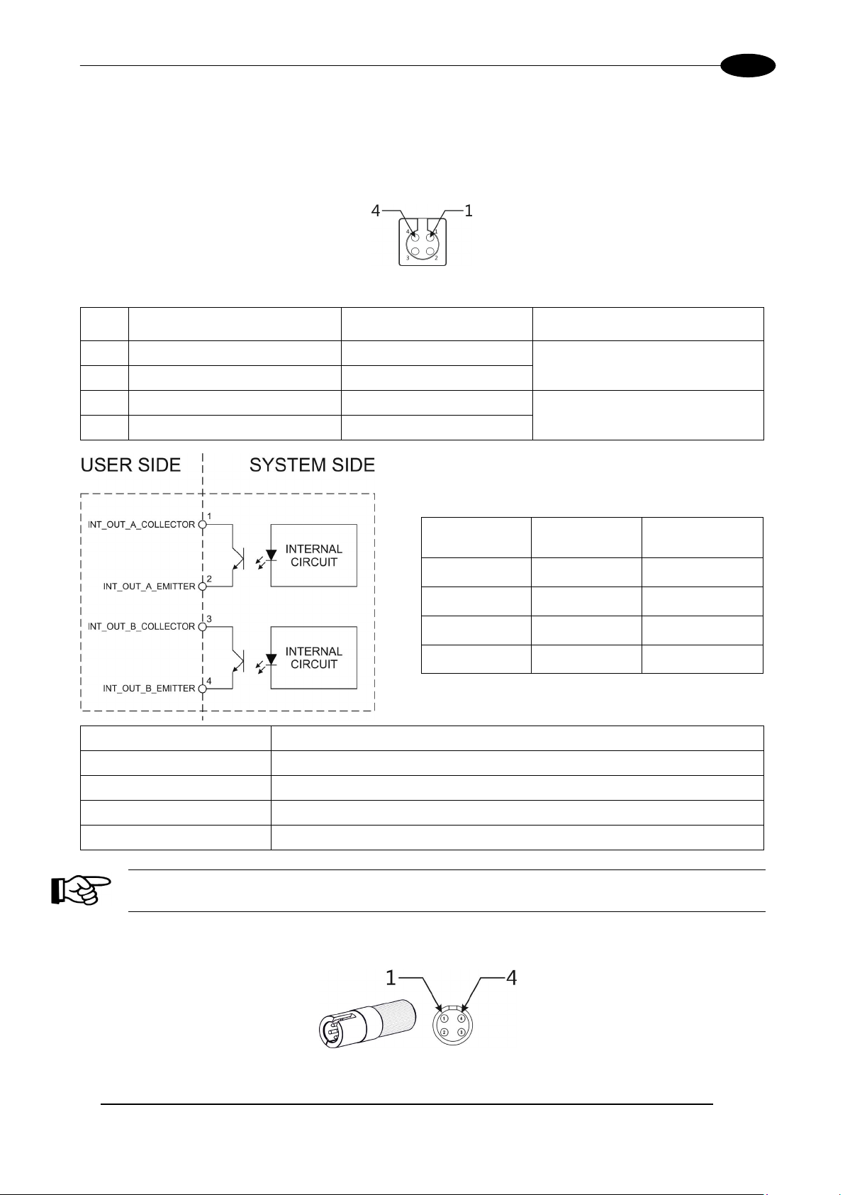
2.4.2 INTERLOCK OUT CONNECTOR
The interlock-out allows to monitoring of the operation of the interlock connector.
PANEL CONNECTOR
Panel socket BINDER, 4 positions female, 719 series.
Figure 16: Female panel socket cod. 09-9766-30-04 (front view).
PIN SIGNAL TYPE DESCRIPTION
1 INT_OUT_A_COLLECTOR COLLECTOR
2 INT_OUT_A_EMITTER EMITTER
3 INT_OUT_B_COLLECTOR COLLECTOR
4 INT_OUT_B_EMITTER EMITTER
Type NPN BJT transistor
V
300 V
max
I
60 mA
max
Vsaturation < 1,5 V
Interlock OUT signal A
(INT_OUT_A)
Interlock OUT signal B
(INT_OUT_B)
INT_OUT_A INT_OUT_B CONDITION
Closed Closed SAFE
Closed Open DANGEROUS
Open Closed DANGEROUS
Open Open DANGEROUS
Leakage current < 400 nA
NOTE:
The response time is 10 ms from the output’s switching.
PLUG CONNECTOR
Binder male cable mount connectors, 719 series, 4 positions.
+
Figure 17: Male cable mount connector cod. 09-9767-00-04 (front view).
Page 26
26
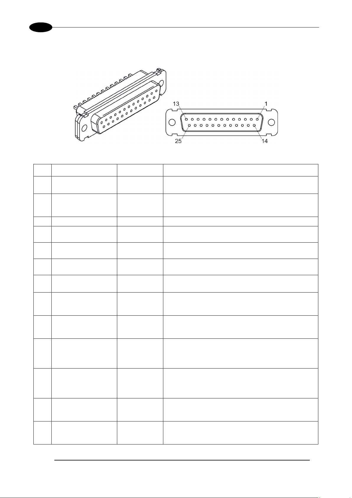
2.4.3 COMMAND BOX CONNECTOR (LASER CONTROL)
Panel socket Sub-D, 25 positions, female.
Figure 18: Female panel socket Sub-D 25 (front view).
PIN SIGNAL TYPE (***) DESCRIPTION
VLASETM UV
1 12V_ENABLE_B
2 EXT_ENABLE_B Digital Input
3 RESERVED Digital Output DO NOT CONNECT
4 EXT_12V
5 EXT_12V
6 EXT_12V
7 12V_ENABLE_A
8 EXT_ENABLE_A Digital Input
9 BUSY (*) Digital Output
CONNECTOR
10
PRESENCE
11 START MARKING (*) Digital Input
12 EXT_KEY Digital Input
13 STOP MARKING (*) Digital Input
Output power
supply
Output power
supply
Output power
supply
Output power
supply
Output power
supply
Digital Input
12V DC power supply available for EXT_ENABLE_B
(max 250mA)
Secondary external ENABLE signal (see par. 2.4.3.1)
- HIGH level: contact closed
- LOW level or disconnected: contact opened
Auxiliary 12V DC power supply available for drive input
logical HIGH (max 250mA)
Auxiliary 12V Dc power supply available for drive input
logical HIGH (max 250mA)
Auxiliary 12V DC power supply available for drive input
logical HIGH (max 250mA)
12V DC power supply available for EXT_ENABLE_A
(max 250mA)
Primary external ENABLE signal (see paragraph 2.4.3.1)
- HIGH level: contact closed;
- LOW level or disconnected: contact opened
This signal is used to know if the current spooler is
executing (marking in progress) (see paragraph 2.4.3.4)
- ON during marking process
This signal is used to check the presence of the
command box connector (see paragraph 2.6)
- HIGH level: normal operation;
- LOW level or disconnected: laser source faulty
This signal is used to start to the marking process when
a document or a sequence is running in AUTO MODE
(**) or WORK MODE (**): (see paragraph 2.4.3.4)
- HIGH level pulsed signal start the marking process
External KEY signal (see paragraph 2.4.3.2)
- HIGH level: contact closed;
- LOW level or disconnected: contact opened
This signal is used to stop the marking process (see
paragraph 2.4.3.4)
- HIGH level pulsed signal stop the marking process
Page 27
TECHNICAL SPECIFICATIONS
27
14 RESERVED Digital Input
15 RESERVED Digital Input DO NOT CONNECT
16 RESERVED Digital Input DO NOT CONNECT
17 END Digital Output
18 POWER_ON Digital Output
19 GND Ground
20 SYSTEM_ALARM Digital Output
21 GND Ground Ground reference
22 ENABLE_OUT Digital Output
23 SW_READY (*) Digital Output
24 GND Ground Ground reference
DO NOT CONNECT
This signal is used to know if the marking process is
finished (see paragraph 2.4.3.4):
- ON at the end of marking process
This signal is used to know if the system is already
warmed up: (see 2.4.3.3)
- ON when the laser is in STAND_BY or READY
state
Ground reference
This signal is used to know if the system is in booting
up state or in error state: (see paragraph 2.4.3.3)
- ON during BOOTING UP
- ON in case of system error
This signal is used to know if the system is ready to
emit laser radiation: (see paragraph 2.4.3.3)
- ON when the system is in READY state
This signal is used to know if a document, sequence or
script is loaded and ready to be executed:
- ON when a document or a sequence is running in
AUTO MODE (**) or WORK MODE (**)
(SW_READY COMPATIBILITY (**) = true)
- ON when a document or a sequence is running in
AUTO MODE (**) and laser in READY state
(SW_READY COMPATIBILITY (**) = false)
- ON when a script is running n AUTO MODE (**)
and “IoPort.setReady (true)” function is used
25 GND Ground
(*) refers to Lighter user’s manual “Setting I/O parameters” paragraph to set the signal properties
(**) refers to Lighter user’s manual
(***) refer to 2.5
Ground reference
NOTE:
Connection example in paragraph 2.6.
Page 28
28
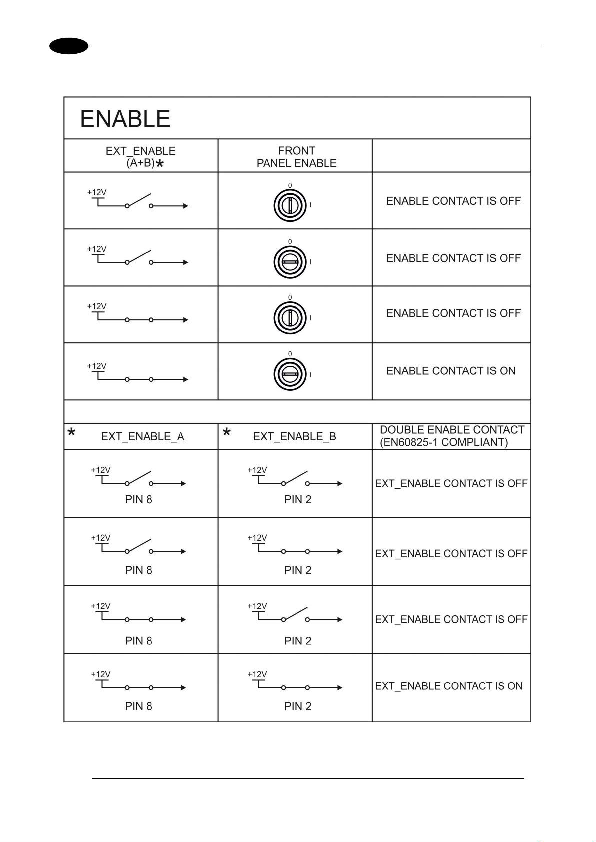
2.4.3.1 ENABLE SIGNAL’S SCHEME (COMMAND BOX CONNECTOR)
VLASETM UV
Figure 19: ENABLE signal’s scheme.
Page 29
TECHNICAL SPECIFICATIONS
29
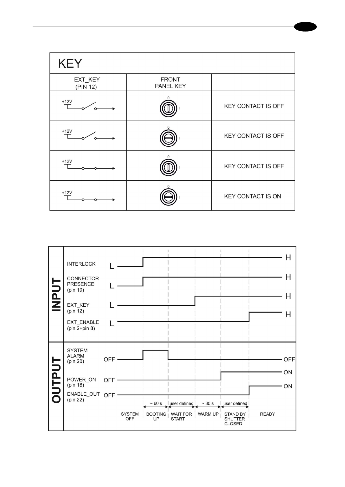
2.4.3.2 KEY SIGNAL’S SCHEME (COMMAND BOX CONNECTOR)
Figure 20: KEY signal’s scheme
2.4.3.3 LASER CONTROL SIGNALS TIMING
Figure 21: Timing control signals
Page 30
30
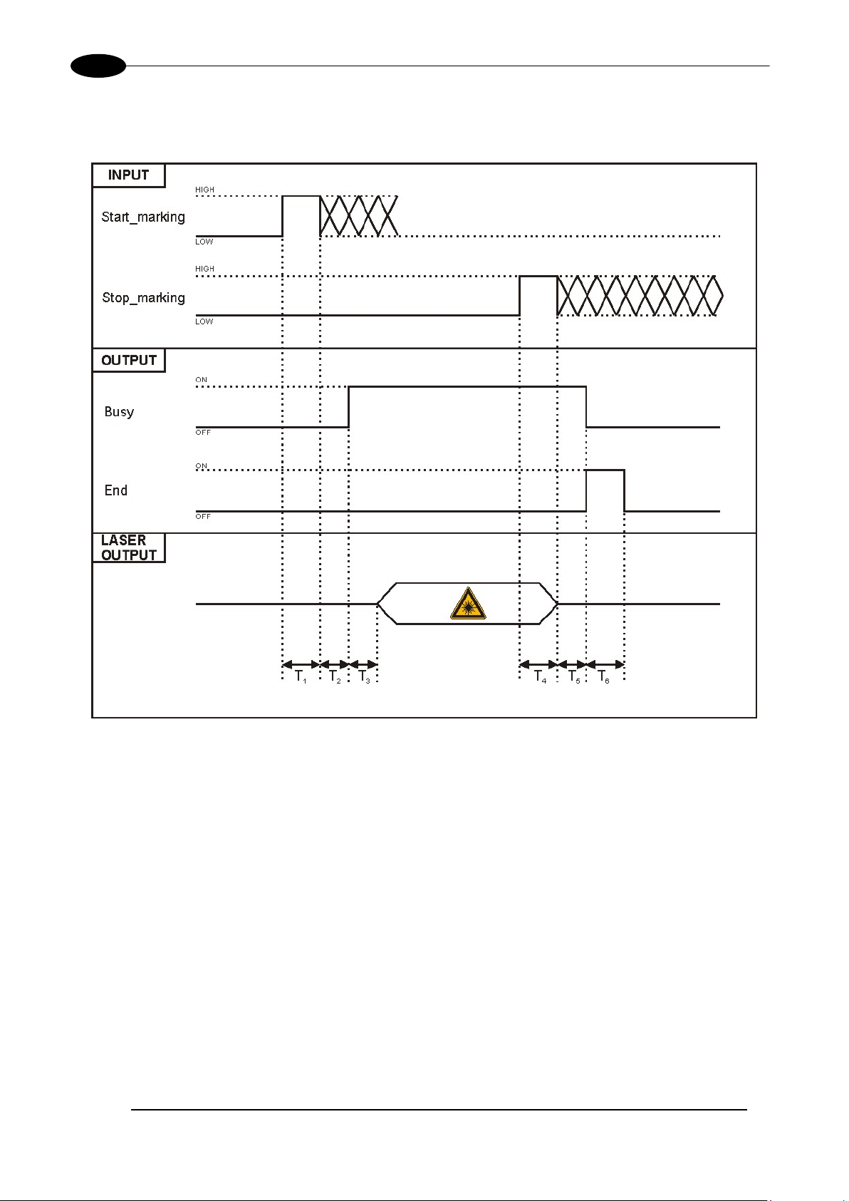
2.4.3.4 TIMING MARKING PROCESS SIGNALS
The following diagram illustrates the possible timings and settings of these signals:
VLASETM UV
Figure 22: Timing signals
The time intervals in the diagram can all be programmed with a resolution of 1 ms
Start Time For setting the minimum acceptable time for the START_MARKING signal
T
1
Start Delay For delaying the start of marking process
T
2
Busy Advance BUSY signal corresponding to marking progress
T
3
T
Stop Time The minimum time for STOP_MARKING signal to stop the marking process
4
Busy Delay For delaying the Laser END signal with respect to laser emission
T
5
End Time For setting the Laser End activation time
T
6
(*) Refer to Lighter user’s manual “Setting I/O parameters” to set the signal’s properties.
(*).
Page 31

TECHNICAL SPECIFICATIONS
31
2.4.4 AXES CONNECTOR (I/O CONTROL)
Panel socket Sub-D, 25 positions, male.
Figure 23: Male panel socket Sub-D 25 (front view).
PIN SIGNAL TYPE (**) DESCRIPTION
1 EXT_12V
OUTPUT_0 (*) or
2
STEP_Y
OUTPUT_2 (*) or
3
STEP_Z
OUTPUT_4 (*) or
4
BRAKE X
OUTPUT_6 (*) or
5
BRAKE Y
OUTPUT_8 (*) or
6
BRAKE Z
INPUT_0 (*) or
7
ZERO X
INPUT_1 (*) or
8
ZERO Y
INPUT_2 (*) or
9
ZERO Z
INPUT_3 (*) or
10
DISABLE X
INPUT_4 (*) or
11
DISABLE Y
INPUT_5 (*) or
12
DISABLE Z
13 GND Ground Ground reference
OUTPUT_12 (*) or
14
STEP R
Output Power
supply
Digital Output
Digital Output
Digital Output
Digital Output
Digital Output
Digital Input
Digital Input
Digital Input
Digital Input
Digital Input
Digital Input
Digital Output
Auxiliary 12V DC power supply available for drive
input logical HIGH (max 250mA)
Generic output or Y-Axis drive step signal (Clock)
for axis control
Generic output or Z-Axis drive step signal (Clock)
for axis control
Generic output or X-Axis electromechanical brake
release signal. ON during drive motion
Generic output or Y-Axis electromechanical brake
release signal. ON during drive motion
Generic output or Z-Axis electromechanical brake
release signal. ON during drive motion
Generic input or X-Axis home sensor input. The
home search is stopped when this signal goes
HIGH
Generic input or Y-Axis home sensor input. The
home search is stopped when this signal goes
HIGH
Generic input or Z-Axis home sensor input. The
home search is stopped when this signal goes
HIGH
Generic input or X-Axis disable signal. When HIGH,
the corresponding step signal remains in the status
prior to activation
Generic input or Y-Axis disable signal. When HIGH,
the corresponding step signal remains in the status
prior to activation
Generic input or Z-Axis disable signal. When HIGH,
the corresponding step signal remains in the status
prior to activation
Generic output or R-Axis drive step signal (Clock)
for axis control
Page 32

VLASETM UV
32
OUTPUT_3 (*) or
DIR Z
OUTPUT_5 (*) or
DIR Y
OUTPUT_7 (*) or
DIR X
OUTPUT_11 (*) or
DIR R
OUTPUT_1 (*) or
15
STEP X
16
Digital Output
Digital Output
Generic output or X-Axis drive step signal (Clock)
for axis control
Generic output or Z-Axis drive direction signal
17
18
19 INPUT 9 Digital Input
20 INPUT 8 Digital Input
INPUT_7 (*) or
21
ZERO R
INPUT_6 (*) or
22
DISABLE R
OUTPUT_9 (*) or
23
BRAKE R
24
25 GND Ground Ground reference
(*) enable an axis cause that t he corresponding signals will no longer be avail able as generic inputs/output. Refers to Light er user’s
manual, “Setting the X, Y, Z, and Rotor Axes parameters” to enable/disable Axes and set the Axes properties.
(**) see paragraph 2.5
Digital Output
Digital Output
Digital Input
Digital Input
Digital Output
Digital Output Generic output or R-Axis drive direction signal
Generic output or Y-Axis drive direction signal
Generic output or X-Axis drive direction signal
Generic Input
Generic Input
Generic input or R-Axis home sensor input. The
home search is stopped when this signal goes
HIGH
Generic input or R-Axis disable signal. When HIGH,
the corresponding step signal remains in the status
prior to activation
Generic output or R-Axis electromechanical brake
release signal. ON during drive motion
2.4.5 RS232 CONNECTOR (COM2)
Panel socket Sub-D, 9 positions, male.
Figure 24: Male panel socket Sub-D 9 (front view).
PIN SIGNAL TYPE DESCRIPTION
1 DCD Input Data Carrier Detect
2 RXD Input Receive Data
3 TXD Output Transmit Data
4 DTR Output Data Terminal Ready
5 GND Ground Ground reference
6 DSR Input Data Set Ready
7 RTS Output Request to Send
8 CTS Input Clear to Send
9 RI Input Ringing Indicator
Page 33

TECHNICAL SPECIFICATIONS
33
2.4.6 ENCODER CONNECTOR
Panel socket BINDER, M12, 8 positions female, 763 s eries. Recommended enc oder : Datalo gic ENC 58-S10XXXX-M1 (ENC58-S10-5000-M12).
Figure 25: Female panel socket cod. 09-3482-87-08 (front view).
PIN SIGNAL TYPE DESCRIPTION
1 GND GND Ground signal
2 VCC POWER OUTPUT 12V DC power supply
3 ENC_A DIGITAL INPUT Encoder HTL A channel signal
4 GND GND Return signal for ENC_A
5 ENC_B DIGITAL INPUT Encoder HTL B channel signal
6 GND GND Return signal for ENC_B
7 NC NC NC
8 NC NC NC
BODY SHIELD SHIELD SHIELD
2.4.7 PHOTOCELL CONNECTOR
Panel socket BINDER, M 12, 4 positions fem ale, 763 series. Recomm ended photocell: Dat alogic S51-PA-5B01-PK; Datalogic S15-PA-5-B01-PK or equivalent.
Figure 26: Female panel socket cod. 09-3482-87-04 (front view).
PIN SIGNAL TYPE DESCRIPTION
1 VCC POWER OUTPUT 12V DC power supply
2 NC NC NC
3 GND GND Ground signal
4 PHOTOCELL DIGITAL INPUT PNP photocell signal
WARNING!
For EMC compliance a RICHCO RRC-16-9-28-M2-K5B (or equivalent) must be used.
Page 34

34
2.5 INPUT/OUTPUT SIGNAL SPECIFICATIONS
DIGITAL INPUT:
Type Optocoupler
V
24V DC
max
I
5mA @ 24V DC
max
Pulse Width ≥ 1ms (debounce)
VLASETM UV
INPUT Logic LOW 0.0 V DC 0.0 V DC 2.0 V DC
INPUT Logic HIGH 5.0 V DC 12.0 V DC 24.0 V DC
MIN TYP MAX
DIGITAL OUTPUT:
Type Low side driver
V
24V DC
max
I
250mA
max
Vsaturation <0.5V DC
Leakage current < 5µA
OUTPUT State ON V ≤ 0.5 V DC; I ≤ 250mA
OUTPUT State OFF V ≤ 24 V DC; I ≤ 5µA
Page 35

TECHNICAL SPECIFICATIONS
35
2.6 CONNECTION EXAMPLES
Figure 27: Connection examples.
Page 36

VLASETM UV
36
3 INSTALLATION AND SET UP
3.1 CONNECTIONS
This section of the manual describes the marking system wiring. Carry out the connecting operations as
described below.
WARNING!
Connect the marking s ystem to others WITHOUT voltage in order to avoi d risk s for the operator a nd
for the marking system.
3.1.1 CONNECTING COMMAND BOX CABLE
Connecting Command Box cable.
Figure 28: Connecting Command Box cable.
NOTE:
The Command Box cable must always be inserted in order to use Ena ble and Ke y on the front panel
of the rack.
Page 37

INSTALLATION AND SET UP
37
3.1.2 CONNECTING INTERLOCK CABLE
Figure 29: Connecting interlock cable.
NOTE:
The interlock cable m ust always be inserted in order to use the marking system. The absence of
such connector locks the system.
3.1.3 CONNECTING INTERLOCK OUT CONNECTOR
Figure 30: Connecting interl o ck OU T connector.
Page 38

38
3.1.4 CONNECTING THE OPTICAL FIBER TO THE CONTROL RACK
Follow the steps listed here below to connect the optical fiber to the control rack:
1) unscrew the four screws holding the cover plate on the rack.
VLASETM UV
Figure 31: Removing the cover plate from the rack.
2) insert the optical fiber into the cable gland without removing its protection cap.
WARNING!
The insertion of the optical f iber is a delicate operatio n. You must mak e sure that the optical fiber is
protected by his cap during insertion in the antenna cable to avoid damage or dirty it.
Figure 32: Passing the optical fiber through the cable gland.
Page 39

INSTALLATION AND SET UP
39
3) insert the optical fiber into the PG cable gland mounted on the rear panel of the rack.
Figure 33: Passing the optical fiber through the PG cable gland.
4) remove the drain plug and tighten to form the fiber diode paying attent ion not to soil or scratch th e fiber
end.
Figure 34: Connection of the optical fiber.
Page 40

40
5) fixing the cable gland on the PG.
VLASETM UV
6) closing rack top cover.
Figure 35: Fixing the cable gland.
Figure 36: Closing cover.
Page 41

INSTALLATION AND SET UP
41
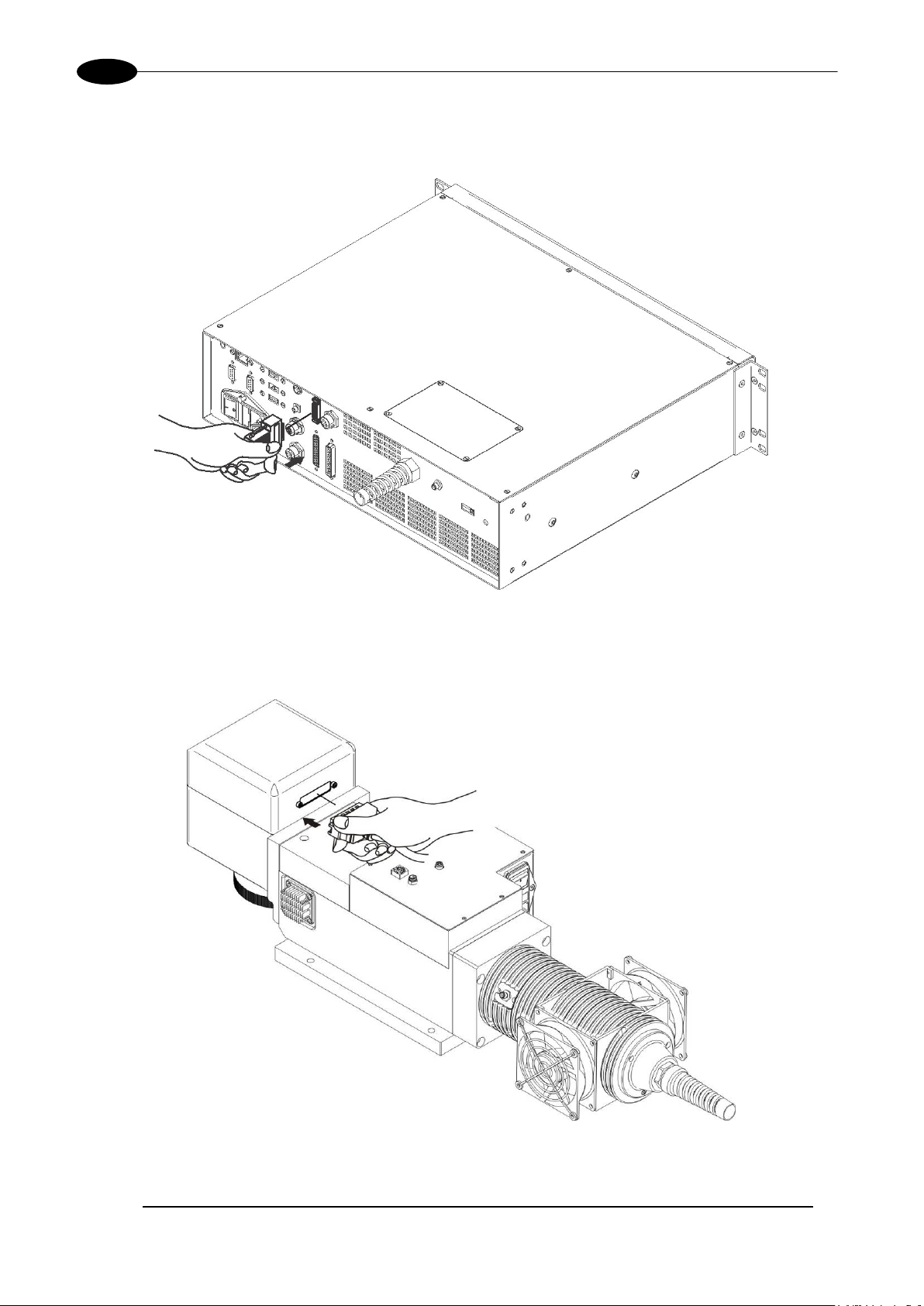
3.1.5 CONNECTING THE OPTICAL FIBER ON THE RESONATOR
Follow the steps listed here below to wire the optical fiber to the resonator:
1) unscrew the three screws that secure the metallic cover and cable gland to the resonator.
Figure 37: Disassembling the optical fiber cable gland from the resonator.
2) insert the optical f ib er in the cab le gland w ithout removing the protection cap.
WARNING!
The insertion of the optical f iber is a delicate operatio n. You must mak e sure that the optical fiber is
protected by his cap during insertion in the antenna cable to avoid damage or dirty it.
Figure 38: Passing the optical fiber through the cable gland.
Page 42

VLASETM UV
42
3) rem ove the protection cap and insert the optica l fiber in the resonator, being car eful not to damage the
end of the fiber or getting it dirty.
Figure 39: Connecting the optical fiber to resonator.
4) screw the protection cap back on the resonator.
Figure 40: Final closing.
WARNING!
To avoid damaging or breaking the optical fiber, never subject it to rays with a curve under 20 cm.
Page 43

INSTALLATION AND SET UP
43
3.1.6 CONNECTING RADIOFREQUENCY CABLE
Screw in SMA connectors, starting at resonator side (90° end) then at the rack side.
Figure 41: RF cable connection.
Page 44
44
3.1.7 CONNECTING MDR CABLE
Connecting MDR cable to rack:
VLASETM UV
Figure 42: MDR connection side rack.
Connect the other end of the cable to the scanner head.
Figure 43: MDR connection side resonator.
Page 45

INSTALLATION AND SET UP
45
3.1.8 CONNECTING RESONATOR CABLE
Connecting resonator cable to rack:
Figure 44: Resonator cable connection side rack.
Connect the other end of the cable to the resonator.
Figure 45: Resonator cable connection side resonator.
Page 46

46
3.1.9 CONNECTING FAN CABLE
Connect fan cable to resonator.
VLASETM UV
Figure 46: Resonator fan cable conne ction.
Page 47

INSTALLATION AND SET UP
47
3.1.10 CONNECTING POWER SUPPLY CABLE
Connecting power supply cable.
Figure 47: Power supply cable connection.
NOTE:
Lock the plug with the retaining clamp to avoid accidental disconnection.
3.1.11 GROUND CONNECTION
To ensure high electrical noise immunity it is strongly recommended to connect the chassis to earth plant.
Figure 48: Ground connection.
Page 48

48
3.1.12 CONNECTING RESONATOR POWER SUPPLY CABLE
Connection the AC power supply to the resonator.
VLASETM UV
Figure 49: Connection the power supply.
Page 49

INSTALLATION AND SET UP
49
3.1.13 LOCAL MODE CONNECTION
To use the marking s ystem in “Local Control” m ode it is necessary to insta ll a m ouse, k eyboard and m onitor
to the system. Connect the monitor and input devices as shown below:
Figure 50: USB mouse connection.
Figure 51: USB keyboard connection.
Page 50

50
Figure 52: VGA monitor connection.
NOTE:
Minimum resolution 800 x 600.
VLASETM UV
3.1.14 REMOTE MODE CONNECTION
To use the marking system in “Remote Mode” it is necessary to connect a network cable:
Figure 53: RJ45 Ethernet connection.
NOTE:
The system LAN is configured by default with a fixed IP Address and Subnet Mask:
- Default IP address: 192.168.0.10
- Default Subnet Mask: 255.255. 255 .0
See chapter 5.2 in order to change LAN configuration.
NOTE:
Ethernet TCP/IP 10, 100 Mbit.
Page 51

INSTALLATION AND SET UP
51
3.1.15 F-THETA LENS PROTECTION CAP REMOVAL
Remove the F-Theta Lens protection cap before marking operation.
Figure 54: F-Theta Lens protection cap removal.
WARNING!
Marking with the lens protection cap could result in damage to the lens.
Page 52

VLASETM UV
52
4 USE AND OPERATION
4.1 TURNING ON S E QUENCE
1ST: before turning on the marking system, be sur e that the system is connected as previous ly described.
Check presence of voltage power supply connection, interlock connector and Command Box connector.
Check that Key and Enable commands on the rack front panel are disabled (see Figure 19 and Figure 20).
ST
: turn on the switch on reso nator. W ait about 20 m inutes bef ore proceedi ng to the nex t step. This waiting
1
time is necessary for the correct warm-up and performance stabilization of the resonator:
Figure 55: Power on resonator.
NOTE:
The warm up time is about 20 minutes with 220V AC power supply. For lower voltage (ie:
110V AC) one should expect a longer wait time.
2ND: turn on the main switch in the back of the control rack:
Figure 56: Power on control rack.
During booting-up, status LED on the rack front panel will be blinking green.
Page 53

USE AND OPERATION
53
Wait the end of the booting-up. The status LED on the rack will be steady green.
Figure 57: Status LED display.
RD
3
: activate the command key, by rotating it clockwise:
Figure 58: Enable signal KEY.
When the KEY signal is e nabled, the status LED on the rac k will be blinking orange for about 20 seconds
(laser source warm-up).
Page 54

VLASETM UV
54
Wait the end of the laser source war m-up. The s tatus LED on the rack and the LED bar on the Scan Hea d
will be steady orange.
Figure 59: Status LED display.
TH
: activ ate the ENABLE command by rotating it clockwise:
4
Figure 60: Enable command ENABLE.
Page 55

USE AND OPERATION
55
KEY
LOW
ENABLE
LOW
SYSTEM_ALARM
ON
POWER ON
OFF
ENABLE OUT
OFF
KEY
LOW
ENABLE
LOW
SYSTEM_ALARM
OFF
POWER ON
OFF
ENABLE OUT
OFF
KEY
HIGH
ENABLE
LOW
SYSTEM_ALARM
OFF
POWER ON
OFF
ENABLE OUT
OFF
KEY
HIGH
ENABLE
LOW
SYSTEM_ALARM
OFF
POWER ON
ON
ENABLE OUT
OFF
KEY
HIGH
ENABLE
HIGH
SYSTEM_ALARM
OFF
POWER ON
ON
ENABLE OUT
ON
STATUS
STATUS LED
OUTPUT STATUS
(*)
SYSTEM_ALARM
OFF
POWER_ON
OFF
ENABLE_OUT
OFF
SYSTEM_ALARM
ON
POWER_ON
OFF
ENABLE_OUT
OFF
The laser system is ready to mark. The status LED on the rack will turn red.
Figure 61: Status LED display.
RESUME TABLE
STATUS ST ATUS LED INPUT STATUS
SYSTEM
BOOTING UP
WAIT FOR START STEADY GREEN
WARMING UP BLINKING ORANGE (1Hz)
STANDBY
SHUTTER CLOSED
READY STEADY RED
WARNING
INVALID START SEQUENCE
BLINKING GREEN (1Hz)
STEADY ORANGE
BLINKING ORANGE (2Hz)
(*)
OUTPUT STATUS
(*)
(*) See paragraph 2.4.3 for more information.
4.1.1 ADVICE ON USING THE SYSTEM
If the marking system is used in manua l mode you need t o connect Com mand Box connect or as described
before. In this way you are able to control the marking system directly on rack front panel.
If the marking system is used in autom atic mode it is recomm ended to enable pe rmanently Key a nd Enable
commands positioned on rack front panel and to use remote signals (EXT_KEY and EXT_ENABLE)
available on Comm and Box connector. T his part is supplied with the product an d you can connect exter nal
controls wiring connector contacts following pins description on chapter 2.6.
SYSTEM ERROR BLINKING RED (2Hz)
Page 56

VLASETM UV
56
Remote Active-X
4.2 LOCAL MODE O PERATIONS
The local mode (with monit or, ke yboard and m ouse co nnected) is optim al to ful ly benefit of the ALL-IN-ONE
Rack architecture characteristics.
SW Editor
SW Engine
+
Correction Matrix
=
Laser Control
Galvo Control
4.3 REMOTE MO DE OPE RATIONS
Keyboard, mouse and monitor are not necessary in this configuration.
LAN
SW Editor
Remote SW Engine
SW Engine
Correction Matrix
Laser Control
Galvo Control
Page 57

USE AND OPERATION
57
New IP ActiveX allows OEM integrators and end-users to create customized Applications and User
Interfaces via Ethernet.
Local or remote Activ eX control inter face is a vailable with the sam e comm ands to al low the use of the same
application developed for both local and remote configurations.
LAN
Remote ActiveX
SW Engine
Correction Matrix
Laser Control
Galvo Control
Page 58

VLASETM UV
58
bers, date
up that allows to o perate the
Laser Engine Tray Icon
4.4 OPERATING IN LOCAL MODE
Connecting monitor, m ouse and keyboard to the l aser system (see paragraph 3.1.13) allows the operat or to
access the console which contains the instruments to operate with laser.
Laser Editor is a software that allows to easily mark or engrave product identification
information such as 2 D matrix codes, barcodes, text, al pha-numeric serial num
codes, part numbers, graphics and logos in any production environment.
With Laser Editor you can:
o edit graphic layouts
o set laser parameters
o set system configuration
o control the integrated I/O module for axis management
o create automated procedures
o create programs using Lighter programming language
Laser Engine is an a pplication automatically loaded a t startmarking system. Laser Engine is present in the tray icon.
With Laser Engine you can:
o monitor the system status
o select a sa ve d doc ument, display limits us ing a r ed laser pointer, watch th e marking
preview and do marking tests
o switch between Manu al/Auto mode (engraving oper ations controlled by operator or
external signals)
Page 59

USE AND OPERATION
59
4.4.1 HOW TO CREATE AND EDIT YOUR FIRST GRAPHIC DOCUMENT
SIGNAL STATUS
EXT_KEY OFF
EXT_ENABLE_A OFF
EXT_ENABLE_B OFF
In “WAIT FOR START” status, double click on Laser Editor icon to start the layout editor application
Click on the document type selector and choose Layer:
Page 60

60
Click on the Text String icon in the Object toolbar to add a string object to the layer:
VLASETM UV
Edit String properties such as value, font, style, etc. using the Properties browser:
Page 61
USE AND OPERATION
61
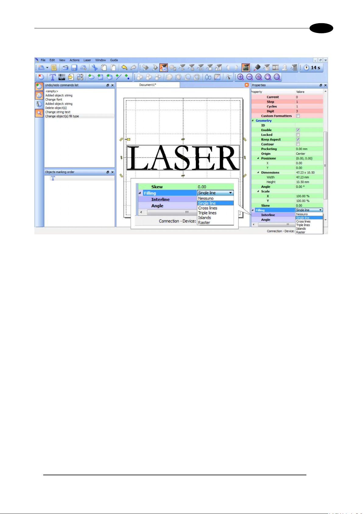
Edit Filling properties such as filling type, interline, etc. using the Properties browser:
Page 62

62
4.4.2 HOW TO TEST AND ENGRAVE YOUR DOCUMENT
SIGNAL STATUS
EXT_KEY ON
VLASETM UV
EXT_ENABLE_A OFF
EXT_ENABLE_B OFF
In “STANDBY SHUTTER CLO SED” status , press Limits All button in the Laser Toolbar t o a dj ust t he objec t
position in the marking field:
Page 63

USE AND OPERATION
63
In “READY” status, adjust the Laser parameters using the Properties browser:
SIGNAL STATUS
EXT_KEY ON
EXT_ENABLE_A ON
EXT_ENABLE_B ON
Press Send Marking button in the La ser Toolbar to start the marking process:
Page 64

VLASETM UV
64
4.4.3 HOW TO USE EXTERNAL SIGNALS TO ENGRAVE YOUR DOCUMENT
Automate the marking process allowing documents to be marked using external START_MARKING and
STOP_MARKING signals, that can be generated by PLC or other external devices.
Click on Save to Device button to save the layout in the marking system memory:
Click on Show Laser Engine button to displa y Laser Engin e windo w :
AUTO/MANUAL Mode button allows switching between the two available working modes:
o Auto mode: the engraving operations are executed automatically using external signals.
o Manual mode: used for displaying the margins of the graphic objects to be marked and testing
layouts.
Page 65

USE AND OPERATION
65
Select the document from the list and click on To Auto Mode button:
The laser system is ready to mark document using external START_MARKING and STOP_MARKING
signals:
Page 66

VLASETM UV
66
4.5 THERMALI ZATION AND SUPPRESSION OF GIANT PULSES
Thermalization is useful in order to obtain a good marking quality.
To obtain uniform markings and work processes is im portant to keep Nd:YVO4 crystal constantl y pumped.
This operation is calle d thermalization and is im plemented supplying t he laser diode with a suita ble level of
current. In this way a cert ain amount of pumping radiation at 808nm exc ites the crystal “but being the Qswitch closed” no laser radiation is emitted by the system.
TM
With the Vlase
Software thermalization
Software thermalization is implemented automatically by the Lighter marking software and consists in
defining, within the m arking project, a certain thermalization l evel at which the crystal is maintaine d during
the non-emission intervals. It is generally recommended to keep the level of therm alization similar to the
power level used for the marking or slightly lower.
source, this procedure can be implemented using Software Thermalization.
Figure 62: Temporal diagram of S oftware Thermalization.
Page 67

USE AND OPERATION
67
Operation in
(CW)
As you can see in the graph shown i n the Figure, during the m arking phas e the Q-Switc h Modulation s ignal
determines the frequency with which the laser pulses are generated, the effect of the LEVEL signal is a
corresponding change in the laser diode current.
Please note that, in order for this to occur, the EMISSION signal has to be active.
NOTE:
Please also note that the c urrent supp lied to the laser dio de is intentio nall y forced to have ris ing and
falling times in the range of 150us . This protection from fast commutations (generate d either from
fast changes of LE VE L s ig nal or f r om EMISSION signal fr ont) is i nten de d t o red u c e damage risk and
extend lifetime of the diode itself
During the thermali zation phas e, the EMI SSION s ignal sta ys active, while the LEVE L signal goes into a preset thermalization level (i.e. 90%) and the Q SW MOD signal stays fixed at 0 V.
At the end of the therm alization phase, befor e starting another m arking phase, the FPK ( First Pulse K illing)
procedure needs to be impl emented i n order to discha rge the cr ystal, thus avoidi ng the gen eration of “giant”
pulses which may cause marking defects as well as damages to the internal optics of the resonator.
.
To discharge the crystal, the Q-Switch is kept closed (Q SW MOD signal at 0 V) and t he E MIS SION signal is
brought to a 0V level for at least 450 microseconds, so as to cut off the current in the laser diode and
consequently the pumping of the crystal (FPK delay).
Laser source
VlaseTM UV 3 W 20 kHz ÷ 80 kHz NO 1,5 µs 450µs
Frequency
interval
Continuous Wave
Q-switch opening
time (Shot Time)
Optimal FPK
delay
WARNING!
It is strongly recomm ended NOT to chang e FPK Shot tim e delay and set, becau se they have been
optimized to ensure the safety of the marking system and the perfor mance marking linked to the high
stability of the laser pulses.
Page 68

VLASETM UV
68
5 CUSTOMIZE THE SYSTEM’S SOFTWARE
5.1 CHANGE O.S. LANGUAGE AND KEYBOARD LAYOUT
The marking system allows you to personalize the op erating system changing t he language used in m enus
and dialogs, languages you can use to enter text and keyboard layout.
NOTE:
In order to perform this setting it is necessary to conn e c t mouse, keyboard and monitor to the system
(see paragraph 3.1.13)
o Turn O FF and ON the s ystem and wait the end of the boo ting-up (the status LED on the rack m ust
be steady green)
o From the main screen click on St art > Control Panel
.
o Select Change display language:
Page 69

CUSTOMIZE THE SYSTEM ‘S SOFTWARE
69
o In Keyboards and Languages select and choose th e desir ed langu age.
o Select Change keyboards to change your keyboard or input language:
Page 70

70
o Select now input languages and pr ess OK:
VLASETM UV
o Close all the open screens and double click on shortcut to save-data.bat icon in the Desktop
screen.
o A mes sage advise you to r estart or shutdown t he system in order t o permanentl y save data. Press
OK:
o Shut down the system in order to save the new settings:
WARNING!
DO NOT turn OFF or UNPLUG the system while Windows® is shutting down.
o WAIT until system shuts down automatically (black screen)
o Power off the system to complete installation
Page 71

CUSTOMIZE THE SYSTEM ‘S SOFTWARE
71
5.2 CHANGE LAN CONFIGURATION AND IP ADDRESS
The system allows you to change the LAN configuration and IP address.
NOTE:
In order to perform this setting it is necessary to connect mouse, keyboard and monitor to the system
(see paragraph 3.1.13
o Turn O FF and ON the s ystem and wait the end of the boo ting-up (the status LED on the rack m ust
be steady green)
o From the main screen click on Start > Control Panel
).
o Select View network status and tasks:
Page 72

72
o In the Network and Sharing Center screen select Change adapter settings:
VLASETM UV
o In the Network Connections screen double click on Local Area Connection
Page 73

CUSTOMIZE THE SYSTEM ‘S SOFTWARE
73
o In the Local Area Connection Properties screen double click on Internet Protocol Version 4
(TCP/IPv4)
o In the Internet Protocol Version 4 (TCP/IPv4) Properties you can change the IP address and
configuration
o Close all the open screens and double click on shortcut to save-data.bat icon in the Desktop
screen.
o A mes sage advise you to res tart or shutdown the s ystem in order t o permanentl y save data. Press
OK:
o Shut down the system in order to save the new settings:
WARNING!
DO NOT turn OFF or UNPLUG the system while Windows® is shutting down.
o WAIT until system shuts down automatically (black screen)
o Power off the system to complete installation
Page 74

VLASETM UV
74
5.3 CHANGE VIDEO SETTING
The system allows you to change the Video setting.
NOTE:
In order to perform this setting it is necessary to conn e c t mouse, keyboard and monitor to the system
(see paragraph 3.1.13
o Turn O FF and ON the s ystem and wait the end of the boo ting-up (the status LED on the rack m ust
be steady green)
o From the main screen click on St art > Control Panel
).
o Select Adjust screen resolution:
Page 75

CUSTOMIZE THE SYSTEM ‘S SOFTWARE
75
o In the Screen Resolution window select the desired Screen resolution and Colour quality:
o Close all the open screens and double click on shortcut to save-data.bat icon in the Desktop
screen.
o A mes sage advise you to res tart or shutdown t he system in order to permanentl y save data. Press
OK:
o Shut down the system in order to save the new settings:
WARNING!
DO NOT turn OFF or UNPLUG the system while Windows® is shutting down.
o WAIT until system shuts down automatically (black screen)
o Power off the system to complete installation
Page 76

VLASETM UV
76
5.4 REMOTE DE S KTO P CO NNE CTION
To connect the laser system to a remote Windows based computer, follow these steps:
o Turn on the marking system
o Make sure that both the marking system and remote computer are connected to the LAN
o Click Start > All Programs > Accessories, and then click Remote Desktop Connection
o Click Options
o In the Computer lis t, type the host name or the IP address of the com puter to which you want to
connect
o T ype the user nam e, passwor d, and dom ain ( if applic able) of an accoun t to wh ich you have allo wed
remote access into the corresponding boxes, and then click Connect
Page 77

CUSTOMIZE THE SYSTEM ‘S SOFTWARE
77
o In the Log On to Windows® dialog box that appear s, t ype the pass word of the a ccount with remote
access privileges into the Password box:
User name: DLA
Password: dla
o In the Log on to list, if applicable, select the domain or rem ote computer that you want, and then
click OK
The remote desktop is displa yed in a wind ow on the d esk top. The rem ote computer is locked dur ing
this session
o To disc onnect the session, click the Close button in the s ession window, and then click OK when
you are prompted to disconnect the Windows session.
Page 78

VLASETM UV
78
Key selec tor
Selector switch for EXT_KEY control signal
Enable selector / ENABLE indicator
Selector switch for both EXT_ENABLE_A and EXT_ENABLE_B control sig nals with LED indicator
for ENABLE_OUT control signal
Alarm indicator
LED indicator for SYSTEM_ALARM control signal
Start button / BUSY indicator
Stop button / END indicator
Pushbutton for STOP_MARKING control signal with LED indicator for END control signal
READY indicator
LED indicator for SW_READY control signal
External connector
6 ACCESSORIES
The accessories listed here below are described for information purposes only, and are not necessarily
included in the pack aging. The minimum contents of the packaging include the main hardware, cables and
keys. For additional information, please refer to paragraph 1.2.
6.1 CONTROL BOX
Control and command device able to manage:
• Warmup the system
• Open the Shutter and enable laser emission
• Start and Stop the mark ing pr oces s
• Show the marking process status
• Show the system error status
Figure 63: Control Box (Ordering no: 985330031).
1
2
3
4
Pushbutton for START_MARKING control signal with LED indicator for BUSY control signal
5
6
7
Connection to Command Box connector
* Refer to Command Box connector (see paragraph 2.4.3) for detailed control signal’s description.
WARNING!
If the Control Box is used, the marking system works in DANGEROUS condition.
Page 79

ACCESSORIES
79
6.2 MARKING ON FLY KIT
The marking on fly kit is available on request. Kit includes: encoder, photocell, cables and plastic reflectors.
Figure 64: Kit MOF (Ordering no: 985330027).
6.3 CABLE KI T LENG TH P LUS
Cable Kit length plus are available on request.
Figure 65: Cable Kit length plus.
Page 80

80
6.4 RACK HANDLE S
Handles for rack fastening are available on request.
Figure 66: handles rack.
VLASETM UV
Page 81

TECHNICAL SUPPORT
81
7 TECHNICAL SUPPORT
7.1 SEALS
The marking system has seals in some areas . The s eal s m us t not be broken or removed for an y reason. T he
sealed parts ma y be open ed on ly and ex clus ivel y by Datalogic.
result in immediate cancellation of the warranty on the entire marking system.
WARNING!
If a customer breaks or remo ves th e seals p lac ed by th e m anufac turer on t he marking system the
warranty on the entire marking system will immediately become “null and void”
WARNING!
The manufacturer shall not be held liable for any non-conforming use of marking s ystem of its
manufacture.
It is forbidden to operate the marking system before the machine it is intended for, has been
declared in conformance with statutory Directives
Breakage of these seals b y a c ustom er s hall
.
.
WARNING!
Access to the internal parts of the control rack is only per mitted for authorized personnel, who have
been trained and instructed on the electrical risks.
Datalogic shall not be held liable for work on electrically charged parts by inadequately trained
personnel!
WARNING!
Access to the internal parts of the scan head is on ly permitted f or authorized personnel, who have
been trained and instructed on the optical risks!
Datalogic shall not be held liable for work on parts by inadequately trained personnel
!
Page 82

VLASETM UV
82
Every 3 months (according to the
7.2 MAINTENANCE
The ordinary maintenance program foresees only simple operations. Some operations consist in a mere
“check” of the operating condition.
The maintenance activiti es must be done in com pliance with the law prescript ions regarding the s afety rules
during the operations.
The following parts/functions have to be controlled:
MAINTENANCE PR O G RAM
COMPONENT OR FUNCTION TYPE OF OPERATION INTERVALS
Weekly: wipe gentl y with a dr y clot h (or
F-Theta Scan Lens Check / Clean
soaked in high purit y isopro pyl alco hol)
or clean it with air blowing
Rack Air filters Clean / Replace
environment and frequency of use)
7.2.1 F-THETA SCAN LENS CLEANING PROCEDURE
WARNING!
Before cleaning the F-Theta scan lens, the marking system MUST be in set SAFE mode:
1- Disable EXT_ENABLE_A and EXT_ENABLE_B.
2- Disable INTERLOCK_A and INTERLOCK_B.
Figure 67: Cleaning F-Theta lens.
Page 83

TECHNICAL SUPPORT
83
7.2.2 AIR FILTER CLEANING PROCEDURE
Figure 68: Remove of air filter.
WARNING!
In order to set the marking system in SAFE mode, disconnect AC power cable before starting
this operation!
1. Turn off key switch on controller unit
2. Disconnect AC power cable
3. Loosen screws of front panel and remove them
4. Remove filter
5. Clean filter with air blow or with neutral detergent and air-dr y i t
6. Reinstall the filter and protective cover
WARNING!
DO NOT install wet filter!
7. If filter cannot be cleaned, replace the filter
8. Suitable filters are available as spare parts
Page 84

VLASETM UV
84
7.3 PRODUCT S UP P O RT AND CUS TO MER SERVICE
Warranty Information
Datalogic reserves t he ri ght to c han ge t he inf or mation and specification c ont ai ner in th is manual without prior
notice.
Product Support
In the unlikely event that the marking system does not function normally and that it requires attention, contact
Datalogic for advice on further on-site fault diagnosis and/or module return.
If the marking s ystem is to be ret urned t o D atalog ic, ens ure th at al l rele vant ret ur n doc um entation is in p lace
before shipment. Det ails of documentation requirem ents and copies can be obt ained where required from
Datalogic.
Pack the marking s ystem in the original packing a nd include all original acces sories and documentati on as
detailed in the original inventory. It is advised that the correct and original packaging is used to prevent
transit damage to t he marking system . If part or all of the original packaging is unavailable, pleas e contact
Datalogic for replacement items. Please take time to complete all return documentation. This can be
obtained from Datalogic and accurate details, diagnosis and comments in the documentation can help
reduce turnaround time for module repair at Datalogic.
Customer Service Contacts
Product Support
support-dla-lasermarking@datalogic.com
Tel: +39 051-3147011
Customer Services
service-dla-lasermarking@datalogic.com
Tel: +39 0331-918001
Company Web Site
www.datalogic.com
For further contact information see the Contact Us link at www.datalogic.com or contact your local distributor.
Page 85

85
APPENDIX A: LABELS IDENTIFICATION
LABEL DESCRIPTION
Identification label
Warning logotype (Laser)
Laser Label (resonator)5
Laser Label (control rack)5
Aperture Label
Label for non-interlock protective housing
Caution, possibility of electric shock
General Warning
5
Maximum output of laser radiation as per definition 3.55 of IEC60825-1 considering single fault conditions.
USB plug
MAC Address
Page 86

86
2xT10A
2xF2A
Rack Fuses
Resonator Fuses
0 - I KEY/ENABLE Positions
COMMAND BOX Command Box connector
AXES (I/O) Control Axes connector
INTERLOCK Interlock Connector
INTERLOCK OUT Interlock OUT Connector
LAN LAN connector
RS232 RS232 connector
VGA VGA connector
PHOT Photocell connector
ENC Encoder connector
RES Resonator connector
MDR Scan Head connector
RF Radio frequency connector
FAN Fan connector
Page 87

87
POSITIONING OF EXTERNAL LABELS
Figure 69: Positioning of exte rnal labels.
Page 88

88
Figure 70: Positioning of exte rnal labels (resonator).
Page 89

89
APPENDIX B: STANDARDS
LASER STANDARDS
The marking system is designed to comply with the applicable sections of these laser standards:
EU : EN60825-1
USA : 21 CFR 1040.10
The marking system is classified as Class 4 Laser Product.
Datalogic, as m anufacturer of marking s ystem, provides a laser which is NOT intended for immediate use,
but it must be connec ted, by ot hers, t o other de vices whic h have the final a im of c reating a laser proc essing
system.
The final system manufacturer MUST ensure the safety of the laser processing machine according to its
standards including the ris k-analysis, implementation of safety measures, certification and tes ting of safety
measures and the production of adequate information for use of the machine.
Datalogic is available f or providing to the s ystem integrator/O EM all the inform ation in its possessio n to help
in complying with applicable standards.
CE COMPLIANCE
CE marking states the compliance of the product with essential requirements listed in the applicable
European directive.
Since the directives and applicable standards are subject to continuous updates, and since Datalogic
promptly adopts these updates, therefore the EU declaration of conformity is a living docum ent.
The EU declaration of conformity is available for competent authorities and customers by Datalogic
commercial reference contacts.
Since 20th April 2016 the m ain European directives applicable to Datal ogic products require to include an
adequate analysis and ass essm ent of the risk(s ). This evaluat ion was c arried out in relatio n to the appl icab le
points of the standards listed in the Declaration of Conformity.
Datalogic products are mainly designed for integration purposes, into more complex systems. For this reason
it is under the responsibility of the system integrator to do a new risk assessment regarding the final
installation.
WARNING!
This is a Class A, Group 2 product acc ording EN55011. I n a Class B enviro nment this produc t m ay
cause radio interference in which case the user may be required to take adequate measures.
FCC COMPLIANCE
Modifications or changes to this m arking system with out the expressed written appro val of Datalogic could
void the authority to use the system.
This system c omplies with PART 15 of the FCC Rules. Operati on is subject to t he following t wo conditions:
(1) This system may not cause harmful interference, and (2) this system must accept any interference
received, including interf er ence wh ich m a y cause undesired operation.
This marking system has been tested and found to comply with the limits for a Class A digital device,
pursuant to part 15 of the F CC Rules. These limits are designed to provide rea sonable protection against
harmful interference when the system is operated in a commercial environment. This marking system
generates, uses, an d can radiate radio frequenc y energy and, if not install ed and used in accordance with
the instruction manual, m ay cause harmful interferen ce to radio communications. Operation of this marking
system in a residentia l area is likely to cause harm ful interference in which c ase the user will be required t o
correct the interference at his own expense.
Page 90

90
APPENDIX C: SAFETY CONSIDERATION ACCORDING TO EN ISO 13489-1:2008
PERFORMANCE LEVEL (PL)
The PL is specified in EN-ISO13849-1. The risk anal ysis will lea d to a PLr (Per f ormance Level required) for a
safety function based on the following graph:
Figure 71: Determining the required Performance Level (PLr).
APPLICATION EXAMPLE
WARNING!
This example relate o nly to the f eatures intr oduced in VlaseTM to assis t in the risk reduction f rom the
laser radiation. An y other risks (mechanical, electrical, etc.) must alwa ys be evaluated and mus t be
taken appropriate risk reduction measures where necessary.
The Machinery Directive and EN 13849-1 are NOT applicable to the product Vlase
The target safety integrity or performance level (e.g. PLd according to ISO13849-1) shall be
determined by the m achine integrator, tak ing into account the mac hinery directive, the harm onized
standards and any sector-specific standard that may apply.
WARNING!
This example is based on the parameters indicated on paragraph “Safety functions of VlaseTM”.
TM
.
Page 91

91
EXAMPLE AUTOMATIC PRODUCTION LINE
In this case the Protective Housing m ay have a guard c apable of being opened or r emoved typica lly only for
service operation (frequency: seldom or occasional):
• Guard opening should only be possible with the aid of a tool.
• Guard safety switch is connected as input of a safety logic and Vlase™ interlock system as
output/input of that safety logic.
• Warning label for access panel according EN60825-1 is provided.
Since the frequenc y is LO W (F1) and the rem ova l of the guard is inte ntiona l, t he MINIMUM REQU IREMENT
as per IEC13849-1 is PLc.
Target: PLr = c
Page 92

92
BLOCK DIAGRAM
SAFETY LOGIC TO VLASETM DETAILS FOR AUTOMATIC PRODUCTION LINE
Page 93

93
PLC SAFETY DIAGRAM
INTERLOCK_A INTERLOCK_B INT_OUT_A INT_OUT_B CONDITION
OPEN OPEN CLOSED CLOSED SAFE
CLOSED OPEN CLOSED OPEN DANGEROUS
OPEN CLOSED OPEN CLOSED DANGEROUS
CLOSED CLOSED OPEN OPEN DANGEROUS
True table in normal condition.
CHARACTERISTICS OF COMPONENTS
DOOR SWITCH: SAFETY SW ITCH, des igned in com pliance with the sta ndard c urrentl y in effect IEC60 947,
EN292, EN60204, EN1088. Two redundant contacts. IP67. B10d=2000000.
SAFETY LOGIC: main component SAFETY PLC min. PLd according EN13849-1. Output type rela ys, min
10mA. To be installed in an IP54 enclosure.
CONCLUSIONS
Because MTTFd is greater than 100 years, Category is 3, DC max achievable is 99% then the PLr=c is
satisfied.
Page 94

94
SAFETY FUNCTIONS OF VLASE
VlaseTM provides inputs,outputs and actuators to implement the following safety functions:
- SF.1 ENABLE (e.g. no IR laser output if "EXT_ENABLE_A" or "EXT_ENABLE_B" are disabled,
where "disabled" means contacts open)
- SF.2 INTERLOCK (e.g. no IR laser output if "INTERLOCK_A" or "INTERLOCK_B" are disabled,
where "disabled" means contacts open)
These functions has been evaluated according to UNI EN ISO 13849-1. The results are:
- SF.1:
- Category: B
- MTTFd <10 years
- DC: none according category
- SF.2:
- Category: 3
- MTTFd = 4496 years
- DC: feedbacks are pr ovided. T he determ ination of the diagnos tic cov erag e (DC%) is then ass igned
to the integrator of the system depending on realized supervision system.
- Response time: 10ms
TM
Page 95

95
WARNING!
u protect yourself
against beams of reflected or direct light
as they cause permanent damage to
your skin.
WARNING!
Staring directly at a laser beam may
cause irreversible damage t o your e yes.
WARNING!
Wear safety goggles while using the
system!
APPENDIX D: NOTE ABOUT LASER
LASER SAFETY
The following inform ation is provided in compliance with regulat ions set by International Authorities, and it
refers to the correct use of marking system.
It is crucial that yo
NOTE:
BEFORE INSTALLING AND USING THE LASER, READ CAREFULLY THE APPENDIX
CONCERNING LASER SAFETY.
Page 96

96
LASER RADIATION
Laser radiation is an electromagnetic emission with a micrometric wa velength which ranges from the long
infrared (CO
ultraviolet (excimer laser).
It should be considered non-Ionizing Radiation. In Vlase
stimulated by “optical pum ping” generated by a Diode Las er. The continuous ref lection of Photons, between
a front mirror and rear mirror, c reates a positive reaction so that their number continues to incre ase, until
reaching the concentr at ion nec ess ary to produce a beam which projects fr om the s emi-reflecting front m ir ror .
The radiation (whic h we can imagine as a “Beam of in visible light”) is then Collimated a nd Focalized with
Lenses at a point where the intensity becomes high enough to be able to react with various materials
producing an alteration in them due to thermal effect.
The radiations of Vlase
entirety without using t he natur al defens e pro vided b y pupil ref lex! Added to th is is the fac t that it is gener all y
very intense, with the result that it can be very harmful to the eye and present vision problems.
To prevent permanent damage to vision, a few precautions must be taken.
All individuals who m a y be ex posed to da ngerous lev els of laser rad iation , m ust kno w that the laser is act ive
and wear protective goggles if necessary.
Laser), close infrared (Nd Laser: Yag, Nd: YVO4), visible (He Laser: Ne or Argon) and
2
TM
marking system, the em ission of a crystal bar is
TM
marking system are visible and invisible and the Eye receives it almost in its
WARNING!
Directly viewing a laser bea m can cause irreversible damage to vision.
Due to its high power, the laser integrated in the Datalogic system provokes reflected las er light from flat
surfaces. Reflected light is potentially dangerous for the eyes and skin. Electromagnetic emission with a
micrometric wave length is placed in long infrared, and is therefore invisible, thus it is not clear where
reflected beams are aimed.
WARNING!
It is indispensable to protect yourself from reflected light beams, because they can be
sufficiently intense to create permanent injury to the eyes or skin
In addition to possible injur y to the e yes or sk in, direc t laser em ission can c ause flam m able materials to bur n
like organic solvents (alcohol, acetone) or gasoline and cause fabric and clothing to burn.
.
WARNING!
This marking system is classified as Class 4. Class 4 includes lasers which can produce ris ks, not
only from direct or reflected radiation, but also fr om scattered rad iation! The laser s ources m ay be
a significant risk for the skin and risk of burning flammable materials
.
Page 97

97
ABSORPTION OF LASER RADIATION
Human skin absorbs electromagnetic radiation in different ways depending on the wave length of the
radiation. Both the eye an d skin have a “predisposition” for accepting certain wave lengths, and ar e more
unresponsive to absorbin g others. In the specific c ase of the Eye, the Corn ea and Crystalline l ens let all the
wave lengths from 400 to 1 400 nm pass and reach the Retin a, even with various attenuations. T hey include
the range from visible light to IR A inf rared. T hus Nd: YVO
this range and leads to direct Retina exposure!
In terms of the Skin, the “biological window” has different absorption percentages but is not dissimilar in
terms of wave length. The maximum exposure values for Skin are much different compared to those
tolerated by the Eye.
laser radia tion ( 355 nm wavelength) is incl uded in
4
Figure 72: Eyeball section.
In terms of the damage m echanism that absorbed ra diation can cause, i t also depends on the wave length.
Short lengths (ultraviolet: UV-C 18 0-280nm; UV-B 280-315 nm , UV-A 315-400 nm) generall y cause photochemical effects:
• cataract, or opacification of the crystalline lens
• melanic coloring, or reddening of the skin
Greater wavelengths (inf rared: I R-A 780-1 400 nm ; I R-B 1400 3000 nm; IR-C 300 0-10
thermal effects:
• detachment or photocoagulation of the retina
• burning of the skin
The degree of injury obviously depends on the amount of absorbed radiation and the instantaneous
power of the radiation source.
E6
nm) gener all y cause
CLASSIFICATION AND DANGER LEVEL
Regulations have esta blished different classes of Las er danger based on the ability to injur e people, from
Laser Class 1 (basically safe in all conditions) to Laser Class 4 dangerous in vario us condi tio ns .
Lasers which can produce risks, not only for direct or reflected radiation, but also for scattered radiation
belong to Class 4. These Laser sources can also have a significant risk for the Skin and fire risk for
flammable material. For these reasons, the User m ust put into effect all measures aim ed at containing the
radiation to make sur e that it is term inated at the end of its useful path. The oper ator mus t also be informed
of the risks from exposure to Laser radiation and mus t wear specific I.P.D. (individual pr otection devices)
including goggles that protect against radiation and are certified as suitable for this use.
WARNING!
The VlaseTM marking system contains a Class 4 invisible laser source.
Page 98

98
RADIATION VIEWING CONDITIONS
The laser output b y th e resonator is to be c ons ider ed as a hi ghly collimated and i ntens e monochromatic lig ht
source. Due to thes e c har acteristics it can be s e en as a “ point source” of h igh l um inos i t y. T his means that its
image is then focalized on t he R et ina in a very small spot with a danger ous ly high power density! If the beam
becomes divergent and sc atters to a non-reflecting sc reen, then there is an “extended v ision” of the image,
with a decisively less dang erous power density. So there are differ ent types of radiation viewing based on
the access to the radiation and consequently different degrees of dangerousness.
DIRECT VIEWING OF THE LASER BEAM
This type of viewing is t he most dangerous and can occur at the outlet of the laser aperture after ha ving
removed the lens. It is to be avoided at all costs ! No protective goggles repre sent a valid means against
direct viewing of the beam.
DIRECT VIEWING OF THE BEAM AFTER MIRROR REFLECTION
This may occur by directing the beam on a reflecting surface.
Viewing of a mirror reflected beam from a flat surface is very dangerous and equal to direct viewing.
DIRECT VIEWING OF THE BEAM OUTPUT BY AN OPTICAL FIBER
This happens if an O ptical Fiber disc onnects from the resonator. View ing of the beam is dangerous up to a
significant distance. Filters and Goggles do not ensure safety.
DIRECT VIEWING OF THE BEAM AFTER FOCUSING
This occurs if the laser beam is not extinguished with an opportune absorber at the end of its useful path .
Looking at the beam is dangerous up to a co nsiderable distance. Filters and goggl es can ensure safet y for
brief exposure, as long as they are the right size and certified.
SCATTERED VIEWING OF THE BEAM AFTER FOCUSING
This is the m ost frequent viewing, but opp ortune Filters and Goggles can ensure safety, even for prolon ged
exposure.
The Nominal Ocular Hazard Distance (N.O.H.D.) for Vlase™ are showed in the next paragraph.
WARNING!
Always use goggles with conformity certificate.
Remember that no goggles can provide prolonged protection from direct or mirror-reflected
radiation
!
Page 99

99
N.O.H.D. DETERMINATION AND O.D. OF PROTECTION GOGGLES
In order to determinate the characteristics of the protection goggles, it is essential to determine the
characteristics of the radiation, knowing its optical path, the dimensions of the beam and its divergence.
In particular, it is very impor tant to know the real divergence of the beam in output f rom the objective (FTheta).
With all these optical data it is possible to calculations of the Nominal O cular Hazard Distance (N.O.H.D.)
and of the optical density (O.D.) requested to the protection filters of the laser radiation.
Calculations have been done following the CEI EN 60825-1 (2014) Normative regarding nominal
distance and optical risk in the worst condition and in case of accident exposure o f 10 seconds for
direct radiation and 100 seconds for diffused radiation.
Wavelength 355 nm
Application type Marking
Emission type Q-Switched
Observation type Direct radiation
Pulse energy
Pulse duration Vlase™ UV 3039-TFS2: 8 ns
Beam Diameter at 9X Beam Expander Output (1/e2) Vlase™ UV 3039-TFS2: 6.0 mm
Beam divergence on the lens Vlase™ UV 3039-TFS2: 0.6 mrad
Vlase™ UV 3039-TFS2: 100 µJ @ 30 kHz
Focal of the F-Theta lens 160 mm
Real divergence after the lens Vlase™ UV 3039-TFS2: 37,5 mrad
Exposure time 10 s
Page 100

100
ACCIDENTAL CONDITION OF VISION OF THE DIRECT REFLECTED RADIATION
Assuming a direct exposition of 10 seconds at a nominal distance of 0,5 m (worst case) is possible to
calculate the suitable optical density for safety goggles.
The O.D. (Optical Density ) in last column assure to reduce laser radiation below max acceptable level:
O.D.= log (H/EMP) where EMP is the Maximum Permissible Exposure and H is the radiant exposure.
Source
Vlase™ UV 21 m > 2.1
SCALE INDEX OF THE PROTECTION GOGGLES FILTER
The scale index L of the filters indicates the sta bility to the radiation, that m eans the ability of the filter to
maintain its character istic s unc han ged . This stability is certif ied by the pr od uc er a c c ording to th e EN 2 07 with
tests conducted for 10 seconds or 100 pulses.
It is then necessar y to ver if y th at t he s c al e ind ex of the adopted filter is stab le f or t his period and fores een an
adequate over dimensioned in order to make sure that it could last longer than the accidental exposure
period.
In case of exposure at 0,5 m for 10 seconds the suggested optical density for safety googles is CLASS L4.
N.O.H.D. (Nominal Ocular Hazard
Distance)
O.D. (Optical Density)
 Loading...