

Page 1
USER’S MANUAL
>Ulyxe PL
TM
Page 2

ii
Datalogic S.r.l.
Via S. Vitalino 13
40012 – Calderara di Reno
Italy
Ulyxe PLTM User’s Manual
Ed.: 06/2017
© 2009 - 2017 Datalogic S.p.A. and/or its affiliates ALL RIGHTS RESERVED. Without
limiting the rights under copyright, no part of this documentation may be reproduced,
stored in or introduced into a retrieval system, or transmitted in any form or by any means,
or for any purpose, without the express written permission of Datalogic S.p.A. and/or its
affiliates. Datalogic and the Datalogic logo are registered trademarks of Datalogic S.p.A. in
many countries, including the U.S.A. and the E.U.
Ulyxe, Ulyxe PL, Lighter Suite are trademarks of Datalogic S.p.A. and/or affiliates. All other
trademarks and brands are property of their respective owners.
Datalogic reserves the right to make modifications and improvements without prior
notification.
Datalogic shall not be liable for technical or editorial errors or omissions contained herein,
nor for incidental or consequential damages resulting from the use of this mat er i al.
821002094 rev. E
Page 3

iii
SYMBOLS
Symbols used in this m anual along with their meaning are show n below. Symbols and signs are repeated
within the chapters and/or sections and have the following meaning:
Generic Warning:
This symbol indicates the need to read the manual carefully or the necessity of an important
maneuver or maintenance operation
.
Electricity Warning:
This symbol indicates d angerous voltage associated with t he laser product, or powerful enough to
constitute an electrical risk. This symbol may also appear on the marking system at the risk area
Laser Warning:
This symbol indicates the danger of exposure t o visible or invisible las er radiation. T his symbol m ay
also appear on the marking system at the risk area
.
.
Fire Warning:
This symbol indicates the d anger of a fire w hen proce ssing flam mable m aterials. Because th ere is a
danger of fire, it is indispensable to follow the instructions provided by the manufacturer when
commissioning the marking system
.
Notice:
Notes, usage tips, or additional information.
Note:
Carefully read the user’s manual before using the marking system.
Page 4

iv
REVISION INDEX
Complete Revision for
Ulyxe PL™ 2.0
Environmental Declaration
Windows® 7 compatibility
Power supply plug and connector;
Prerequisites for inst al lat ion
Revision Date Number of added or edited pages
A 03-03-2009
B 15-10-2009 Datalogic Automation f ormat
C 12-03-2010 Standards References
D 27-09-2010
821002090 rev. A 02-05-2012
821002091 rev. B 20-06-2012 General Review
821002092 rev. C 10-04-2014 12, 23, 48, 49 Appendix E
821002093 rev. D 13-06-2016
821002094 rev. E 06-06-2017
General Review
ii
NOTE:
We sometimes update the documentation after original publication. Therefore, you should also
review the documentation on www.datalogic.com for any updates.
Page 5
v
FOREWORD
Information included in this manual is intended for a qualif ied installer able to integrate the marking
system into a s ystem, complying with all the protection features required by international rules and
local legislations. Refer to the Appendices for further information.
Following manual refers to an UlyxeTM 1PWX-T15 marking system in Class 4 configuration.
In addition to being pr ofessionally trained in their ro le, personnel assigned to wor k on the marking system
must be informed and made acquainted w ith the risks inherent to invisible and visible laser radiation. The
operator is required to caref ully read the section of the m anual concerning safet y instructions as well as the
sections related to matters falling under her/his responsibility.
The workers assigned to the marking system can be identified as:
OPERATOR
•
responsible for loading elements to be processed, visually checking the work cycle, removing the
finished product and cleaning the marking system.
MAINTENANCE PERSONNEL
•
responsible for the electrical, mechanical and optical maintenance and adjustment of the marking
system.
WARNING!
Datalogic shall not be held responsible for any non-conforming use of marking system of its
manufacture
.
NOTE:
BEFORE INSTALLING AND USING THE LASER, READ CAREFULLY THE APPENDICES.
PATENTS
See www.patents.datalogic.com for patent list.
This product is covered by one or more of the following patents:
Utility patents: IT1366132, US7480318
Page 6
vi
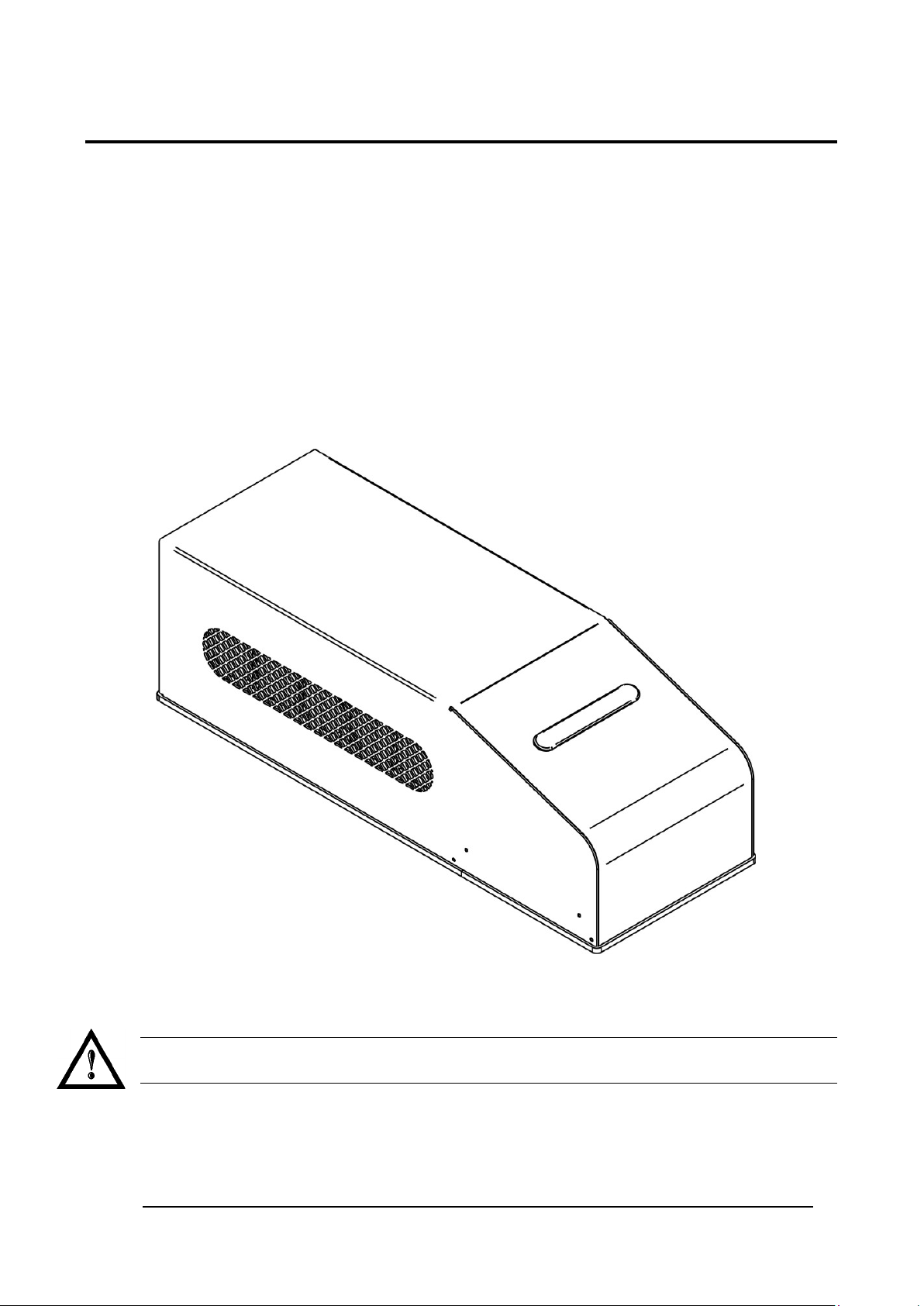
OVERVIEW
We are satisfied of your ch oice for a Datalogic product and especiall y for an “ALL IN ONE” compact s ystem
made from experience years in laser marking field.
The marking s ystem Ul yxe P L
laser category.
It’s simple and compact design conveys a versatile, intuitive and easy product to integrate due to its
advanced technology.
Easy to use, it can be the best investment to entry in the laser world without compromises about
performance and to obtain excellent markings.
Ulyxe PLTM system includes all necessary to operate, a laser source DPSS Q-switched, a galvanometer
scanning head, digital power controls, cooling system and monitoring functions. The entire unit and its
mechanical base are covered with a metal casing that makes it more resistant to external agents.
The user can easily interac t s and monitors laser status and its f unc tions with an ea sy use of an external LCD
Touch Screen control display (optional).
TM
belongs to a Diode Pum ped Solid State (DPSS) Q-switched side pumped
Figure 1:Overview.
WARNING!
Marking system installation in secure environment is responsibility of the system integrator!
Page 7

vii
IMPORTANT WARNING
Access to the interna l part s of the marking system is al lo wed o nly to authorized personnel, duly qualified and
trained with regards to risks of optical and electrical nature.
Datalogic declines a ny and all responsib ility for work carr ied out on live parts b y untrained or unauthor ized
personnel.
WARNING!
It’s not allowed modify destination use of the marking system in different way of its functions.
Datalogic declines any responsibility and liability for irregular and improper use of the marking
system which it manufactures.
WARNING!
These marking system actuation is demanded to the system integrator.
Page 8

viii
USB 2.0 ADVICE
Ulyxe PL™ exclusively works via USB 2.0 Full Speed only. Certain hardware configurations and certain
operative systems do not fully support the requested connection.
It is suggested to perform the following checks:
• Use only USB cables certified “ HIGH SPEED” or quality “USB2.0” cable, not longer than 2 meters.
• Avoid using any kind of extension cable or any HUB on the cable path.
• Verify the compatibility of the operative system.
• Some computers support only one USB2.0 at a time. On those system s, the use of other devices
(USB memories, ex ternal H D, etc.) can disconnect the U l yx e P L ™ peripheral devices (in par ticul ar it
is observed that any US B 2.0 peripheral connected for las t in temporal order isn’t recogni zed from
O.S.).
Page 9

ix
TABLE OF CONTENTS
SYMBOLS III
REVISION INDEX IV
FOREWORD V
PATENTS v
OVERVIEW VI
IMPORTANT WARNING vii
USB 2.0 ADVICE VIII
TABLE OF CONTENTS IX
1. CONTENTS OF THE PACKAGING 11
1.1 UNPACKING 11
1.2 MAIN HARDWARE 12
1.3 CABLE AND ACCESSORIES 12
1.4 TRANSPORT 13
1.5 ON MOISTURE CONDENSATION 13
1.6 FIXING AND POSITIONING 14
1.7 INSTALLATION ENVIRONMENT 15
1.8 FUME / DUST EXTRACTOR 15
2. TECHNICAL SPECIFICATIONS 16
2.1 TECHNICAL SPEC IF IC ATION 16
2.2 DESCRIPTION OF THE LASER
2.3 MARKING AREA SPEC IF I C AT I ON 19
2.4 CONNECTORS SPECIFICATIONS 21
2.4.1 AUX INTERLOCK CONNECTOR (SW LEVEL) 21
2.4.2 CONTROL BOX CONNECTOR (LASER CONTROL) 22
2.4.3 POWER SUPPLY CONNECTOR 24
2.4.4 POWER SUPPLY CABLE 24
2.4.5 RS232 CONNECTOR 24
2.5 INPUT/OUTPUT SIGNAL SPECIFICATIONS 25
2.6 CONNECTION EXAMPLE 26
3. INSTALLATION AND SET UP 28
3.1 LIGHTER SUITE INSTALLATION 28
3.2 CONNECTIONS 33
3.2.1 CONTROL BOX CONNECTOR CONNECTION 33
3.2.2 AUX INTERLOCK CONNECTION 34
3.2.3 POWER SUPPLY CABLE CONNECTION 34
3.2.4 USB CONNECTION 35
3.2.5 F-THETA LENS PROTECTION CAP REMOVAL 36
MODULES 18
4. USE AND OPERATIONS 37
4.1 TURNING ON SEQUENCE 37
Page 10

x
5. ACCESSORIES 41
5.1 CONTROL BOX 41
5.2 POWER SUPPLY ULYXE™ FAMILY 42
5.3 REMOTE CAN DISPLAY 43
6. TECHNICAL SUPPORT 47
6.1 SEALS 47
6.2 MAINTENANCE 48
6.2.1 F-THETA SCAN LENS CLEANING PROCEDURE 48
6.3 TROUBLESHOOTING 49
6.3.1 LIST OF POSSIBLE MALFUNCTIONS 49
6.3.2 ERROR MESSAGE S 51
6.4 PRODUCT SUPPORT AND CUSTOMER SERVICE 54
APPENDIX A: LABELS IDENTIFICATION 55
LABELS LOCATI ON 56
APPENDIX B: STANDARDS 57
LASER STANDARDS 57
CE COMPLIANCE 57
FCC COMPLIANCE 57
APPENDIX C: NOTE ABOUT LASER 58
LASER SAFET Y 58
LASER RADIATIO N 59
ABSORPTION OF LASER RADIATION 60
CLASSIFICATION AND DANGER LEVEL 60
RADIATION VIEWING CONDITIONS 61
DIRECT VIEWING OF THE LASER BEAM 61
DIRECT VIEWING OF THE BEAM AFTER MIRROR REFLECTION 61
DIRECT VIEWING OF THE BEAM OUTPUT BY AN OPTICAL FIBER 61
DIRECT VIEWING OF THE BEAM AFTER FOCUSING 61
SCATTERED VIEWING OF THE BEAM AFTER FOCUSING 61
REAL O.R.N.D. DETERMINATION AND O.D. OF PROTECTION GOGGLES 62
EYES AND SKIN RISKS 64
GENERAL SAFETY REGULATIONS 64
COLLATERAL RISKS 64
APPENDIX D: MECHANICAL DRAWINGS 66
FIGURES 67
Page 11
CONTENTS OF THE PACKAGING
11
1. CONTENTS OF THE PACKAGING
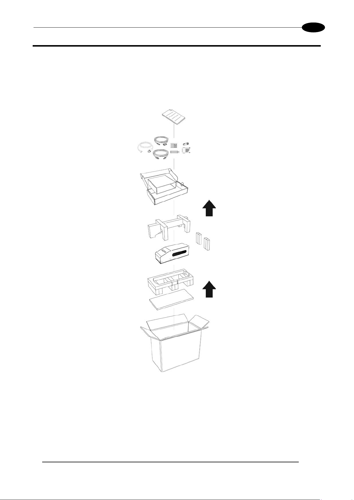
1.1 UNPACKING
When unpacking the marking system from the shipping carton you should:
• Remove the documentation from the top of the marking system
• Remove the box containing the accessories
• Carefully remove the marking system from the packaging using both hands
Figure 2: Unpacking.
Before installing or operating the marking system, you should:
• Inspect the shipping container for damage
• Inspect the marking system for signs of damage
• Confirm that the shipping carton contains all items on the shipping inventory list including any
accessories
Retain all packaging m aterials until the marking syste m has been inspect ed for complete ness and damage ,
and you have checked the operating performance. If anything is missing or defective, see chapter 6 for
contact details.
Page 12

12
1.2 MAIN HARDWARE
Ulyxe PL™ F-Theta (except 1PWX-T0SV)
1.3 CABLE AND ACCESSORIES
Ulyxe PLTM
Power supply cable
Aux Interlock connector
gold (*)
USB cable
RS232 cable
USB key
Control Box connector
User Manual
* If this connector is used, the marking system works in DANGEROUS condition (MUTING DEVICE).
Test Report
Sample Test
Page 13
CONTENTS OF THE PACKAGING
13
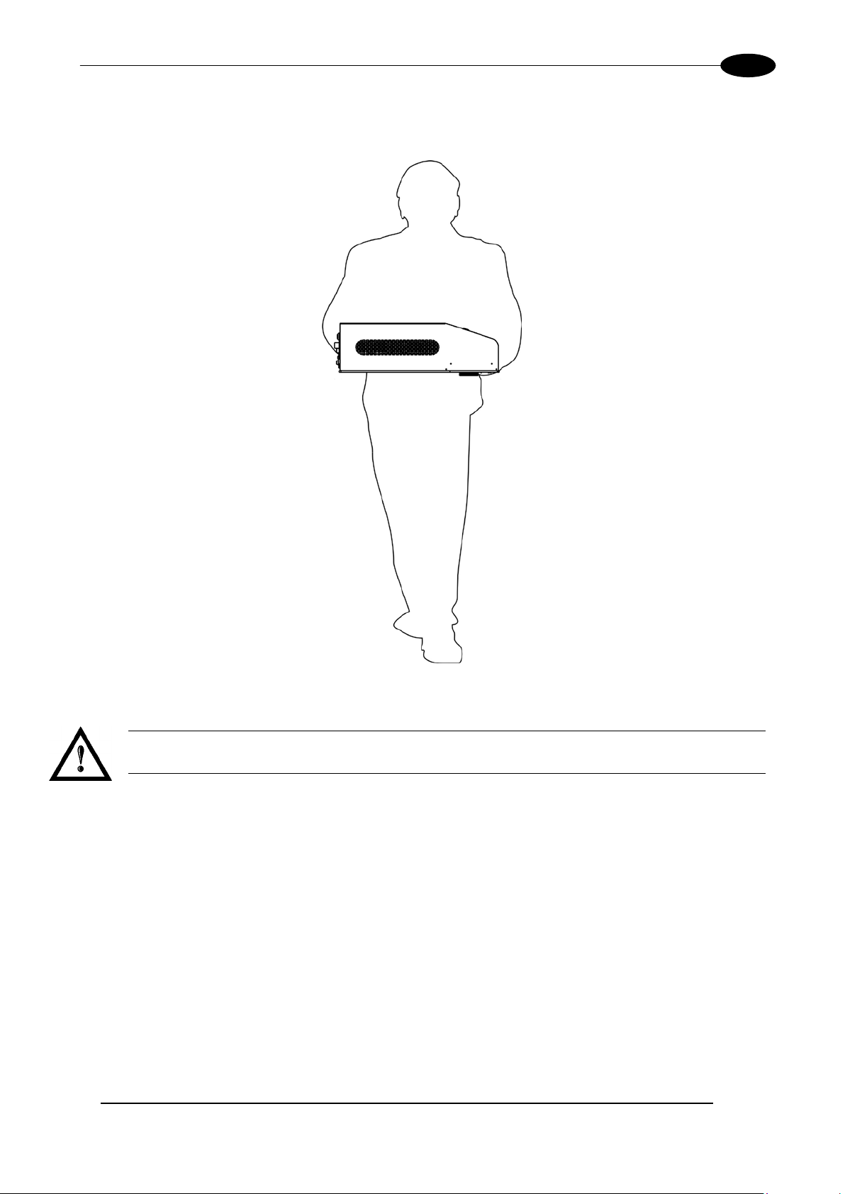
1.4 TRANSPORT
The marking system c an be easily lifted up and moved by a singl e person thanks to its compact si ze and
reduced weight.
Figure 3: Transport.
WARNING!
The Ulyx e P L™ is a delicate optical marking system, avoid damaging it with shock and vibrations.
1.5 ON MOISTURE CONDENSATION
If the marking s ystem is brought directly from a cold to a warm location, moistur e may condense inside or
outside the marking system. This moisture condensation may cause a malfunction of the marking system.
If moisture condensation occurs
Turn off the marking system and wait about 1 hour for the moisture to evaporate.
Note on moisture condensation
Moisture may condens e when you bring the m arking system from a c old place into a warm place (or vice
versa) or when you use the marking system in a humid place as shown below.
How to avoid moisture condensation
When you bring the mark ing system from a cold place into a warm place, put it in a plastic ba g and seal it
tightly. Remove the bag when the air temperature inside the plastic bag has reached the ambient
temperature (after about 1 hour).
Page 14
Ulyxe PLTM
14
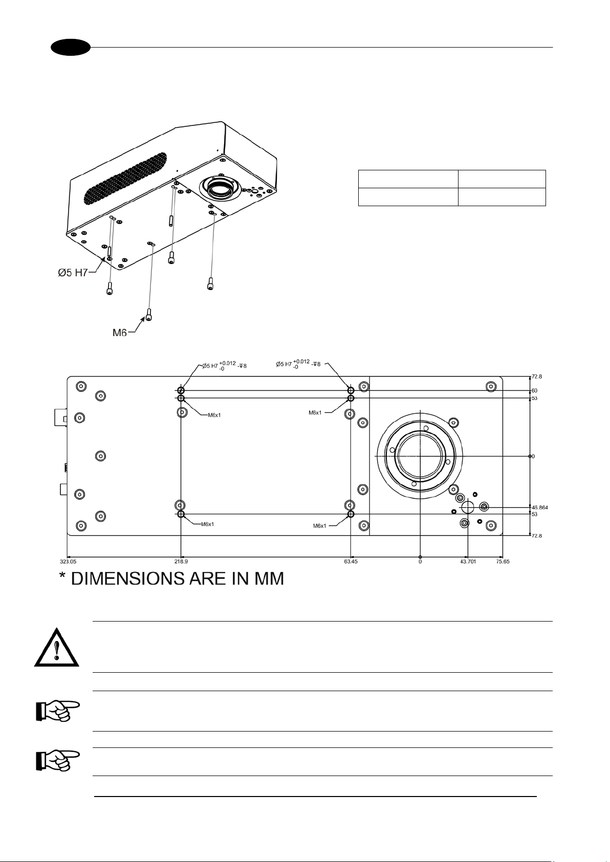
1.6 FIXING AND POSITIONING
The marking s ystem need to be positio ned in safety mode and fixed on an appr opriate plan absolut ely with
no vibrations.
Ulyxe PLTM is equipped with 4 threaded
holes and 2 fixing pins.
Screws M6
Fixing pins Ø5 H7
Figure 4: Fixing points.
Figure 5: Measures, distance threaded holes and fixing pins drivers.
WARNING!
It is very important to secu re the marking s ystem before you start m arking the piece sinc e improper
securing or positioning may cause serious damage. Do not secure the marking system in a way
other than the one described in the figure.
NOTE:
In order to prevent m arking distor tions, chec k for the absence of vibrations bet ween m arking s ystem
and piece to be marked.
NOTE:
It is recommended to install the marking system on a micrometer positioning Z-axis system!
Page 15
CONTENTS OF THE PACKAGING
15
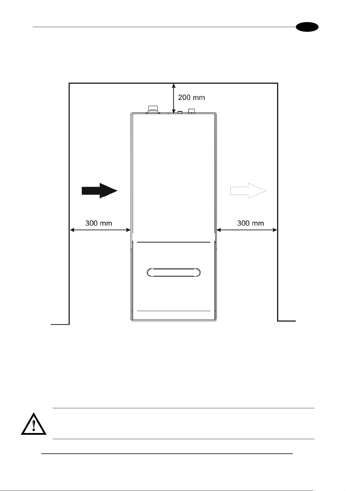
1.7 INSTALLATION ENVIRONMENT
The marking system must be installed in a suitable environment in order to allow proper air flow passage and
correct housing of the cables.
Ulyxe PL
cooling. Installation must not slow or stop the flow of air cooling. Moreover, do not install a heat source near.
TM
is an air cooled marking system, an adequate air flow is necessary to guarantee its correct
Figure 6: Installation environment.
To obtain a good m arking quality, and n ot to decrease lif e time, we recomm ended a ventilation or vacuum
system in a protection box to limit dust due to marking phase.
1.8 FUME / DUST EXTRACTOR
During marking proc ess, dust and/or gas may be produc ed. It is important to use adequat e fume extractor
and/or air filtration.
WARNING!
Marking PVC (or other plas tic material) can cause the release of chlorine gas which can be harmful
to the laser operator and t o the marking system itself. Alwa ys use adequate fume extractor dur ing
PVC and plastic marking.
Page 16

16
2. TECHNICAL SPECIFICATIONS
NOTE:
BEFORE INSTALLING AND USING THE LASER, RE AD CAREFULLY THE APPENDIXES.
WARNING!
Ulyxe PLTM is a CLASS 4 LASER PRODUCT and it is the responsibility of the OEM/system
integrator to provide the safety completeness to be ready-to-use.
2.1 TECHNICAL SPECIFICATION
MECHANICAL CHARACTERISTICS
Ulyxe PLTM
* without F-Theta scan lens
** in horizontal position only
NOTE:
Refer to Datalogic’s website for detailed drawings.
Weight 7.8 Kg
Height * 123.5 mm
Width 145.6 mm
Depth 410 mm
IP Rating ** 21
Page 17

TECHNICAL SPECIFICATIONS
17
Storage temperature
-5° to 55°C (23° to 131°F)
Environmental temperature
15°C to 35°C (59° to 95°F)
Humidity
< 90% without condensation
Altitude
< 1000 m
Suspended matter
< 3 mg/m3
Pollution Degree
2
Overvoltage Categor y
II
Input Voltage
24V DC
Max Power
300 W
LASER MARKER SOURCE (typical values @ 25°C)
Laser Type
Class 4 DPSSL (Diode Pumped Solid State Laser)
Average Power @ reference
Rep Rate (50kHz)1
Pulse energy (max) @
reference Rep Rate (15kHz)
Repetition Rate
kHz
15 ÷ 200
Laser aiming beam Class 2 <1mW @ 630-670nm
Cooling
Forced Air
Noise
dB(A)
< 70 @ 1 meter
OTHER
Char Marking Speed
2
char/s
Up to 275 char/s @ 2000 mm/s
Software Control
Lighter Suite
STORAGE AND TRASPORTATION CONDITIONS
Shock and vibrations The components are not designed to withstand shocks and vibrations
WARNING!
This product includes precision optical parts; avoid vibration and shocks: marking quality may deteriorate.
ENVIRONMENTAL OPERATING CONDITIONS
ELECTRICAL POWER SUPPLY
Input Current 13 A max
PERFORMANCE
W 6.5
mJ 0.30
Central emission wavelength nm 1064
Focus aiming beam Class 2 <1mW @ 630-670nm
Marking Speed mm/s Up to 5000 mm/s
Communication 1x USB (type B), RS232, digital I/O
1
Without F-Theta
2
h char=1mm in Roman-S Level100% f=40kHz F-Theta160S on TESA label
Page 18
18
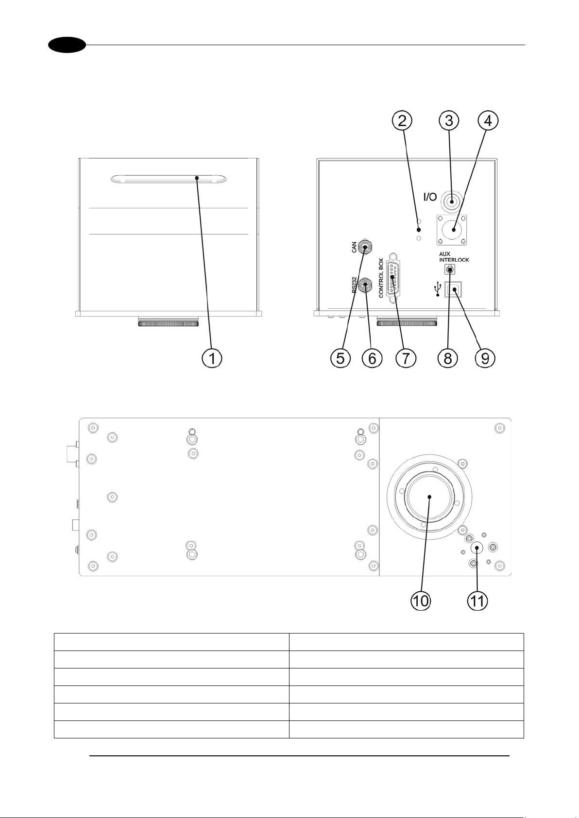
2.2 DESCRIPTION OF THE LASER MODULES
A description of the main parts of the marking sy stem is provided here below:
Ulyxe PLTM
Figure 7: Marking system view.
1) Status LED bar 7) Control Box connector
2) LED indicators 8) Aux Interlock connector
3) Main Switch with LED 9) USB port (type B)
4) Power supply connector 10) F-Theta Scan Lens
5) CAN connector 11) Focusing beam
6) RS232 port
Page 19
TECHNICAL SPECIFICATIONS
19
ƒ
ƒ
ƒ
2.3 MARKING AREA SPECIFICATI O N
Datalogic provid es a wide range of F-Theta scan lens es to be attached to the scanning head to foc us the
laser beam in flat Marking Field, in order to achieve high-resolution marking results.
These F-Theta scan lense s are available to best-match the object (i.e.: logo; string; 2D matrix; etc.) to be
marked with custom er need, over the material processing, an d fit the standard Datalogic Sca nning Head;
further solutions about different models of lenses and scanning heads will be considered upon request.
The table below lists the standard F-Theta scan lenses currently available:
F-Theta Scan Lens diameter: M39
F-Theta Scan Lens
Working Distance (WD) mm 114 178 282
Marking Area (MA) mm
2
= 100S
50 x 50 100 x 100 140 x 140
= 160S
= 254S
NOTE:
Definition of Marking Area: square marking field measured on black anodized aluminium plate.
WARNING!
This product was d esigned to use only certain conf igurations of F-Theta lens and mark ing field. If
your needs are not satisfied by current available F-Theta lens configurations please contact
Datalogic for a solution. T he use of other F-T heta lenses or operation o utside the specif ied marking
field for a certain F-Theta l ens configuration can lea d to damage of F-Theta lens, scanning head or
laser source. Such damage is not covered by warranty!
WARNING!
For each F-Theta lens conf iguration Datalo gic recomm ends the use of cer tain adapter. This ada pter
ensures that residual back ref lections cause d by F-T heta lens do not dam age optics of the scanni ng
head. The removal of such adapter or its incorrect use (for example incomplete thread ing, use of
another F-Theta lens a dapter, etc .) can lead to damage of the F-Theta le ns, scannin g head or las er
source. Such damage is not covered by warranty!
Page 20
20
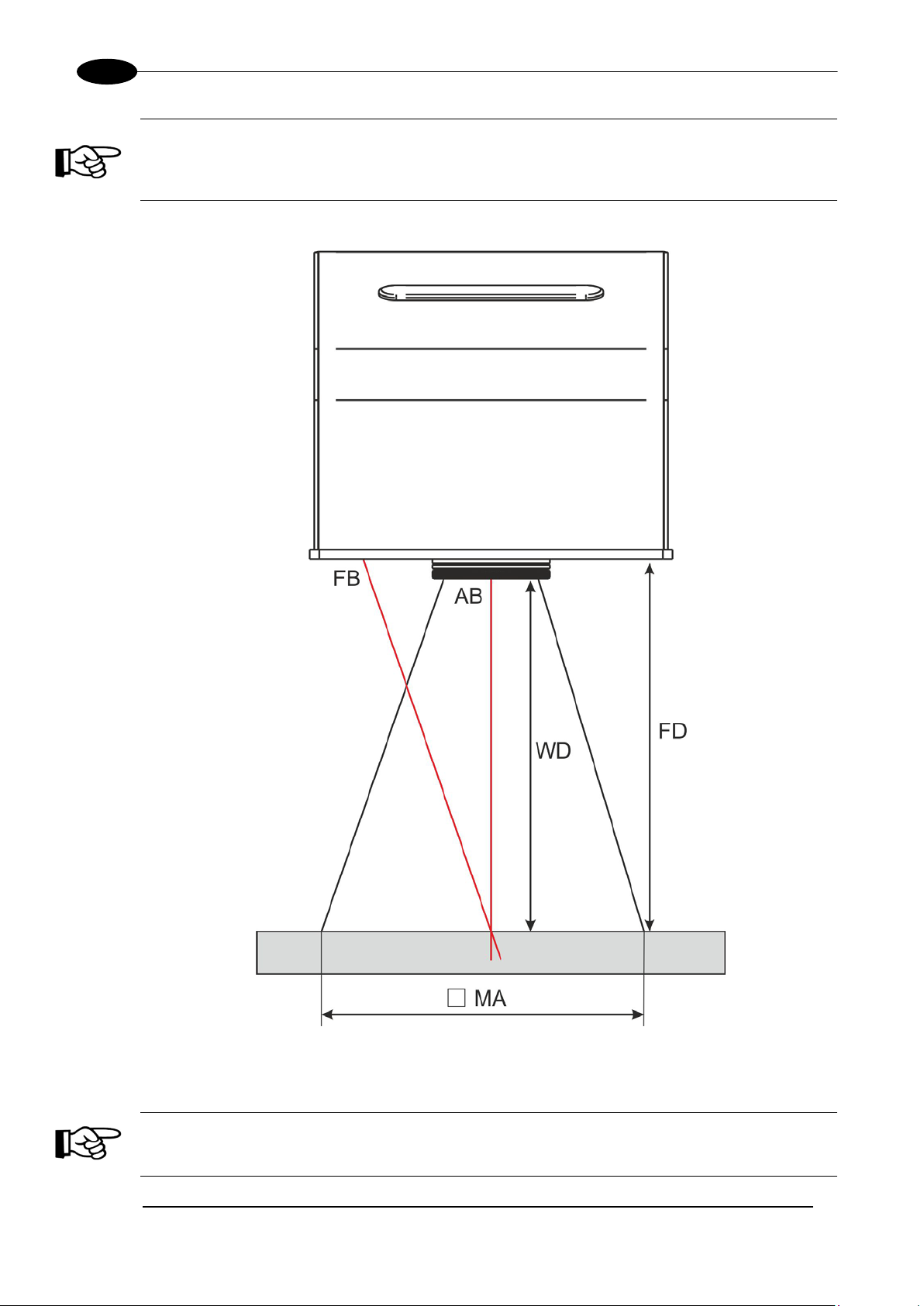
NOTE:
Working Distance is defin ed as the distance between the center of the marking area (defined
in the focal plane) and the last mechanical edge of the F-Theta Scan Lens. Refer to the
following figure.
WD: Working Distance
FD: Fixing Distance
MA: Marking Area
AB: Aiming beam
FB: Focusing beam
Ulyxe PLTM
Figure 8: Marking area.
NOTE:
For systems equipped with standard F-Theta Scan Lens the focus condition is obtained by
matching the Aiming Beam with the Focusing beam.
Page 21
TECHNICAL SPECIFICATIONS
21
2.4 CONNECTORS SPECIFICATIONS
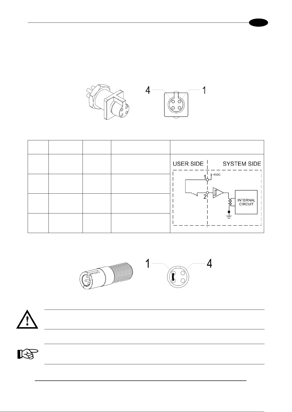
2.4.1 AUX INTERLOCK CONNECTOR (SW LEVEL)
Aux Interlock disables the Class 4 laser source inside the marking system.
PANEL CONNECTOR
Type BINDER 719 series panel mount connector, 4 positions.
Figure 9: Female panel socket cod. 09-9766-30-04 (front view).
PIN SIGNAL TYPE DESCRIPTION FUNCTIONAL DIAGRAM
1 VCC OUTPUT
2 INTERLOCK INPUT INTERLOCK signal
3 GND GROUND DO NOT CONNECT
4 N.C. - NOT USED
PLUG CONNECTOR
Connector type BINDER 719 series, 4 positions.
Figure 10: Male plug connector cod. 09-9767-00-04 (front view).
5V DC for INTERLOCK
signal
WARNING!
If the Aux interlock gold connector is used, the marking system is in DANGEROUS condition
(MUTING DEVICE).
NOTE:
To restore the mark ing system it is necessary to repeat the “Turning on sequenc e” without shutting
down the system. See chapter 4.1
for more details.
Page 22

22
2.4.2 CONTROL BOX CONNECTOR (LASER CONTROL)
Output power
supply
Auxiliary 5V DC power supply available for drive input log ical
HIGH (max 200mA)
External “Shutter Enable” signal (see paragraph 2.4.2.1):
- LOW level or disconnected: Shutter closed
This signal is used to start to the marking process when a
- HIGH level pulsed signal start the marking process
This signal is used to stop the marking process (see
- HIGH level pulsed signal stop the marking process
This signal is used to know if a document, sequence or script
“IoPort.setReady (true)” function is used
This signal is used to know if the current spooler is executing
- ON during marking process
This signal is used to know if the marking process is finished
- ON at the end of marking process
9
RESERVED
CAN_PWR
DO NOT CONNECT
External “KEY” signal (see paragraph 2.4.2.1):
- LOW level or disconnected: system disabled
11
RESERVED
CAN_H
DO NOT CONNECT
This signal is used to know if the system is ready to emit
- ON when the system is in READY state
13
RESERVED
CAN_L
DO NOT CONNECT
14
RESERVED
CAN_GND
DO NOT CONNECT
15
GROUND
Ground
Ground
Panel socket Sub-D, 15 positions, female.
Figure 11: Female panel socket Sub-D15 (front view).
PIN SIGNAL TYPE (***) DESCRIPTION
1, 2 5V DC
Ulyxe PLTM
3 SHUTTER EN Digital Input
4 START (*) Digital Input
5 STOP (*) Digital Input
6 READY (*)
7 BUSY (*)
8 END (*)
Digital
Output
Digital
Output
Digital
Output
- HIGH level: Shutter opened
document or a sequence is running in AUTO MODE (**) or
WORK MODE (**) (see paragraph
paragraph 2.4.2.2):
is loaded and ready to be executed:
- ON when a document or a sequence is running in AUTO
MODE (**) or WORK MODE (**) (SW_READY
COMPATIBILITY (**) = true)
- ON when a document or a sequence is running in AUTO
MODE (**) and laser in READY state (SW_READY
COMPATIBILITY (**) = false)
- ON when a script is running n AUTO MODE (**) and
(marking in progress) (see paragraph 2.4.2.2):
(see paragraph 2.4.2.2):
2.4.2.2):
10 KEY Digital input
SHUTTER OPEN/
12
ALARM
(*) refers to Lighter user’s manual “Setting I/O parameters” paragraph to set the signal properties
(**) refers to Lighter user’s manual
(***) refers to paragraph 2.5
Digital
Output
NOTE:
Connection example in paragraph 2.6.
- HIGH level: system enabled;
laser radiation (see paragraph 2.4.2.1):
Page 23

TECHNICAL SPECIFICATIONS
23
2.4.2.1 LASER CONTROL SIGNALS TIMING
Figure 12: Timing control signals.
2.4.2.2 MARKING PROCESS SIGNALS TIMING
The following diagram illustrates the possible timings and settings of these signals:
Figure 13: Timing signals.
The time intervals in the diagram can all be programmed by a resolution of 1 ms.
Start Time For setting the minimum acceptable time for the start marking signal
T
1
Start Delay For delaying marking start
T
2
Busy Advance BUSY signal corresponding to mark progress
T
3
Stop Time The minimum time for STOP signal to stop the marking process
T
4
Busy Delay For delaying the Laser END signal with respect to laser emission
T
5
End Time For setting the Laser END activation time
T
6
Page 24

24
2.4.3 POWER SUPPLY CONNECTOR
Panel socket SOURIAU TRIM TRIO 4 positions, cod. UT0010-4SH.
Figure 14: Female panel socket cod. UT0010-4SH (front view).
PIN SIGNAL TYPE DESCRIPTION
A +24V Power supply input Power supply input +24V DC (13A MAX)
B 0V Power supply input reference Power supply input reference
C FG Earth Earth connection
Ulyxe PLTM
D N.C. - NOT USED
2.4.4 POWER SUPPLY CABLE
Male plug connector SOURIAU TRIM TRIO 4 ways, cod. UT0610-4PH, 3 meter length.
Figure 15: Male plug connector cod. UT0610-4PH (front view) and wiring.
2.4.5 RS232 CONNECTOR
Connector type BINDER 768 series, 3 positions.
Figure 16: Female panel socket cod. 99-3412-281-03 (front view).
PIN SIGNAL TYPE DESCRIPTION
1 TXD Output Transmit Data
4 RXD Input Receive Data
3 GND Ground Ground reference
Page 25

TECHNICAL SPECIFICATIONS
25
2.5 INPUT/OUTPUT SIGNAL SPECIFICATIONS
DIGITAL INPUT:
Type Digital Isolator
V
7.0 V DC
max
I
1 mA @ 5 V DC
max
Pulse Width ≥ 1ms (debounce)
INPUT Logic LOW 0.0 V DC 0.0 V DC 1.0 V DC
INPUT Logic HIGH 3.5 V DC 5.0 V DC 7.0 V DC
MIN TYP MAX
DIGITAL OUTPUT:
Type Darlington open collector low-side
V
50 V DC
max
I
150 mA
max
Vsaturation <0.5 V DC
Leakage current < 5 µA
OUTPUT State ON V ≤ 0.3 V DC; I ≤ 150mA
OUTPUT State OFF V ≤ 5.0 V DC; I ≤ 5µA
Page 26

26
2.6 CONNECTION EXAMPLE
Ulyxe PLTM
Figure 17: Connection example.
WARNING!
It is important to ins tall an emergen cy circuit ab le to cut 24 V DC power supply voltage (or indirec tly
on 110/220V AC) switching off Ulyxe PL™
qualified personnel only.
entirel y. This safety circuit needs to be installed from
Page 27

TECHNICAL SPECIFICATIONS
27
EXAMPLE OF CONNECTION TO PLC
Figure 18: Example of connection to PLC.
Page 28

Ulyxe PLTM
28
3. INSTA LLATION AND SET UP
3.1 LIGHTER SUITE INSTALLATION
Lighter Suite s oftware need to be insta lled on a PC or a laptop that will be used with Ulyxe PL™ b y an U SB
2.0 connection. T o be able to insta ll a nd op er ate with L ight er Suite on PC following minimal requirements are
needed:
Processor
Operative System
RAM Memory
Hard Disk
Graphic card
USB
Furthers
WARNING!
Connect Ulyxe PL™ to PC through USB cable only after Lighter Suite soft ware ins tal lat ion. DO NOT
CONNECT USB cable until it is not required from installer.
NOTE:
Ulyx e P L ™ works only and exclusive ly with U SB 2.0 F ull Speed d evice co nnectio ns. For a ny further
information consult USB 2.0 ADVICE
32 bit (x86) processor or 64 bit (x64) at 1GHz or highest
Windows
Ultimate; Windows
Windows
1 Gb (32 bit) or 2 Gb (64 bit)
1 Gb of free space on hard disk (32 bit) or 2 GB (64 bit)
Minimal resolution 800 x 600 (1280 x 1024 recommended)
USB 2.0
RS232 serial port
®
XP SP3 Professional; Windows® Vista Business, Enterprise or
®
10 Pro or Enterprise
®
7 Professional or Enterprise, Windows® 8 Pro or Enterprise,
chapter.
NOTE:
Administrator rights are required for Microsoft® Windows® 7/8/10.
Lighter Suite installer executable file is located on USB key supplied with the marking system. Proceed
following below instructions:
1) Insert USB key on the PC that will be used to drive the Ulyxe PL™;
2) Run Lighter Suite executable installer located on the USB pen drive;
Page 29

INSTALLATION AND SET UP
29
3) Wait while Setup is loading;
4) Press Next to continue;
5) Press I Agre e to accept licence agreement;
Page 30

30
6) Select “INTERACTIVE” installation type press Next to continue;
Ulyxe PLTM
7) Select the components to install and press Next to continue;
Page 31

INSTALLATION AND SET UP
31
8) Choose the destination folder and press Install to continue;
9) Provide laser configuration f ile located on USB pen drive supplied with eq uipment and press Open to
continue;
Page 32

32
10) Microsoft® Windows® will ask you to install the device driver; press Install to continue;
11) Wait while Lighter Suite is installing;
Ulyxe PLTM
12) Press Finish to complete the installation;
Page 33

INSTALLATION AND SET UP
33
3.2 CONNECTIONS
This section of the m anual describes the m arking system c onnections. Carry out the c onnecting operations
as described below.
WARNING!
Connect the marking system to other parts WITHOUT voltage in order to a void risk s for the operat or
and for the laser source.
WARNING!
Connect Ulyxe PL™ to PC through USB cable only after Lighter Suite software installation.
3.2.1 CONTROL BOX CONNECTOR CONNECTION
Figure 19: Connecting Control Box connector.
NOTE:
The Control Box connector must always be inserted and wired properly in order to us e the marking
system. If this connection is not present the marking system goes in error status.
In option it is possible to use Control Box accessory (see chapter 5.1
)
NOTE:
Refer to paragraph 2.6 for a connection example of the Control Box Connector.
Page 34

34
3.2.2 AUX INTERLOCK CONNECTION
Plug Aux interlock connector to marking system.
Figure 20: Connecting Aux interlock connector.
WARNING!
If the Aux interlock gold connector is used, the marking system is in DANGEROUS condition
(MUTING DEVICE)
Ulyxe PLTM
NOTE:
The Aux inter lock cable must always be insert ed in or d er to us e t he marking system. The absence of
such connector locks the marking system.
3.2.3 POWER SUPPLY CABLE CONNECTION
Connect power suppl y cable to Ul yxe PL™. Check connector right orientation an d plug in. Once pl ugged in
check also right coupling between two connectors parts.
Figure 21: Power Supply cable plu g in.
WARNING!
Ulyxe PL™ needs a safety circuit for emergency. Consult chapter 2.6 for more details.
WARNING!
Ulyxe PL™ needs a 24V DC stabilized supply voltage 13A max current absorption. It is suggested to
use BOXED POWER SU P PLY KIT option. See chapter 5.2
.
Page 35

INSTALLATION AND SET UP
35
3.2.4 USB CONNECTION
WARNING!
Connect Ulyxe PLTM to PC through USB cable only after Lighter Suite software installation.
Plug USB cable first on Ulyxe PL™ device side
Figure 22: Plug USB system side.
Plug USB cable to PC side
Figure 23: Plug USB PC side.
Wait while Microsoft
A message in the Laser Engine tray icon will advise you that Ulyxe PL™ is plugged in
®
Windows® is installing device drivers
Page 36

36
3.2.5 F-THETA LENS PROTECTION CAP REMOVAL
Remove the F-Theta Lens protection cap before marking operation.
Ulyxe PLTM
Figure 24: F-Theta Lens protection cap removal.
WARNING!
Marking with the lens protection cap could result in damage to the lens.
Page 37

USE AND OPERATIONS
37
4. USE AND OPERA TIONS
4.1 TURNING ON SEQUENCE
Before turn ing on t he mark ing system , be sure t hat the system is connecte d as pr eviousl y describe d. Check
presence of voltage power supply connection, Aux interlock connector, Control Box connector and USB
cable as described in the previous chapter.
SIGNAL STATUS
KEY OFF
SHUTTER EN OFF
1ST step: turn on the main switch in the back of the marking system:
Figure 25: Power on.
If power supply input is correct green LED indicator on back panel will light on otherwise if there is a
reversed voltage input red LED indic ator on back panel will light on. Refer to troubleshoot ing paragraph in
case of error:
Figure 26: Green and red LED on back panel.
Page 38

Ulyxe PLTM
38
The fans cooling system will be po wered on and it will be s howed LCD firm ware version on remote display
temporarily (if pres ent), then LED bar will be lighted on in orange colour unti l system power o n time will be
not completed:
REMOTE CAN
LCD
STARTING SYSTEM
Please Wait
Figure 27: Starting system.
Immediately after LED bar is lighted off Ulyxe PL™ remains in waiting f or key star t mode and po wer m odule
is off:
REMOTE CAN
LCD
WAITING FOR START
[turn on the key]
Figure 28: Waiting for key start.
N
2
step: activate “KEY” si gnal to s tart Ulyxe PL™ and wait for system warm up. During this operation LED
bar will come green blinking.
SIGNAL STATUS
KEY ON
SHUTTER EN OFF
WARM UP
PLEASE WAIT
Figure 29: Waiting for warm up.
Once warm up is completed the LED bar comes steady green and the marking system is ready to use:
REMOTE
CAN
LCD
Figure 30: Ulyxe PL™ waiting ENABLE command.
Page 39

USE AND OPERATIONS
39
NOTE:
If aiming and focusing (optional) beam laser diodes setup are in automatic mode they’ll be light on.
Figure 31: Stand-by system status.
NOTE:
Ulyxe PL™ is ready for operation. See chapter 5.3 for Touch Screen display functions.
NOTE:
For information about use of Lighter software, see related manual.
3TH step: activate “SHUTTER EN” c ommand to open mechani cal shutter. LED bar com es steady orange.
“ALARM” signal will be active and yellow LED indicator on back panel will light on.
SIGNAL STATUS
KEY ON
SHUTTER EN ON
Figure 32: Orange LED Bar: stand-by system
.
Page 40

40
Figure 33: Yellow LED indica to r on back panel.
Ulyxe PLTM
WARNING!
The marking system is READY to mark!
NOTE:
If aiming and focusing beam laser diodes setup are in automatic mode they’ll be light off.
If marking operation starts LED bar comes steady red and on remote display will be showed laser emis sion
status:
Figure 34: Laser emission.
Figure 35: Red LED bar: laser emission.
Page 41

ACCESSORIES
41
I/O connection
Connection to Ulyxe™ Control Box connector
SHUTTER ENABLE
Selector switch with LED indicator to open shutter
ALARM LED indicator
LED indicator for system in “READY” state
START marking / BUSY LED indicator
“START” marking command pushbutton with “BUSY” LED indicator
STOP marking / END LED indicator
READY LED indicator
“READY” for marking LED indicator
KEY
Selector “KEY” to enable the system
5. ACCESSORIES
The accessories listed here below are described for information purposes only, and are not necessarily
included in the pack aging. The minim um contents of the pack aging include the m ain hardware, cables and
keys. For additional information, please refer to paragraph 1.2.
5.1 CONTROL BOX
Ulyxe PL™ control and command device to manage laser power on, to open shutter, to start and stop
marking and to show system status.
Figure 36: Control Box (Ordering no: 985330001).
1
2
3
4
5
“STOP” marking command pushbu tton with “END” LED indicator
6
7
WARNING!
If the Control Box is used, the marking system works in DANGEROUS condition.
Page 42

Ulyxe PLTM
42
Input to ground 2.5kV AC, Input to Output 3kV AV, Output
to ground 500V AC
5.2 POWER SUPPLY ULYXE™ FAMILY
AC/DC stabilized power supply with front cover, power inlet plug, power on mains witch and cables.
Figure 37: Power supply Ulyxe™ family (Ordering no: 985340000).
LAMBDA HWS300-24
Output voltage
Input voltage
Size
Withstand Voltage
Isolation voltage
Mark
EMI compliance
Immunity compliance
Safety Agency Approvals
24V DC, 14A (≈ 300W), Ripple Noise 150mV
85-265 V AC (47-63Hz)
61 x 82 x 165 mm
>100MΩ, Output to ground 500V DC
CE Mark
EN55011 / EN55022, FCC, VCCI Class B
IEC61000-4-2, -3, -4, -5, -6 (Level 3), -8 (Level 4), -11
UL60950-1, CSA60950-1, EN60950-1, EN50178, UL508
Figure 38: Power supply overall dimensions.
Page 43

ACCESSORIES
43
5.3 REMOTE CAN DISPLAY
Ulyx e PL™ doesn’t have LCD displa y inside but it is possible to request rem ote kit option. In this way it is
feasible to check system status, operative parameters, error messages and to setup aiming beam and
focusing beam diodes functionality.
It is comprehensive of Touch Screen displa y, connection cable f or Ulyxe PL™ with 2 mt length an d a metal
cover with fixing elements.
Figure 39: Remote CAN display and cable.
Figure 40: Remote CAN display overall dimensions.
Selection areas Touch Screen.
Figure 41: Selection areas Touch Screen.
Page 44

Ulyxe PLTM
44
LcdFW: F30902001_005
TecFW: F30901003_001
Serial: LSVLL123456
Hr Diode: 0001:23:47
Diode Temp. [°C]: 25.34
SetPoint [°C]: 25.00
Diode Curr. [A]: 12.00
Max Current [A]: 30.00
TEC Voltage [V]: 10.00
TEC Current [A]: 06.12
Board Temp.[°C]: 28.22
Input Voltg [V]: 24.00
Heatsink T. [°C]: 26.12
Serial: LSVLL123456
Hr System : 0001:23:47
SETUP
AIMING BEAM
FOCUSING BEAM
ON
ON
ON
OFF
AUTO
ON
OFF
AUTO
WAITING FOR START
[turn on the key]
WARM UP
Please wait
System OFF
System warm up
System s tandby/ready
Pushing touch-s c r een
SYSTEM MONITOR
menu selection
STAND BY
SERVICE
LASER MONITOR
SERVICE
SYSTEM
LASER M
menu selection
menu selection
STAND BY
STAND BY
menu selection
STAND BY
menu selection
STAND BY
menu selection
STAND BY
Status system
Language: English
STAND BY
STAND BY
STAND BY
STAND BY
STAND BY
System Temp [°C]: 28.34
home
more
home
more
home
more
home
more
home
more
home
morehome
more
menu selection
STAND BY
menu
more
more
STAND BY
STAND BY
STAND BY
STAND BY
mode
mode
Save
Save
SETUP
menu selection
home
more
STAND BY
REMOTE CAN
LCD
REMOTE
CAN
LCD
From display main wind ow where it shows system “READY” it is possib le to acces s to a menu lis t with more
options to select and view as showed in figure.
Figure 42: Display Touch Screen menu.
Page 45

ACCESSORIES
45
menu sele
STAND BY
SERVIC
ho
more
to return to the main screen with the
SY
menu sele
STAND BY
ho
more
return to the main screen with the
LAS
menu sel
STAND BY
ho
more
urn to the main screen with the
SETUP
menu se
ho
more
STAND BY
to the main screen with the
Lc
Te
La
STAND BY
Press the bottom left arrow to return to the main screen with the
B
In
H
STAND BY
S
Information contained in the SYSTEM MONITOR menu (1 of 2).
oard for the power
System Temp. [°C]: Environment temperature measured inside the
Press the bottom left arrow to return to the main screen with the
Press the bottom right arrow to access the following information.
T
TE
S
H
STAND BY
Press the bottom left arrow to return to the main screen with the
Selection menu to display general SERVICE.
• Press the middle area to select it and display the information.
• Press the bottom left arrow
REMOTE CAN LCD logo.
• Press the bottom right arrow to access the next selection menu.
Selection menu to display SYSTEM MONITOR.
• Press the middle area to select it and display the data.
• Press the bottom left arrow to
REMOTE CAN LCD logo.
• Press the bottom right arrow to access the next selection menu.
Selection menu to display LASER MONITOR.
• Press the middle area to select it and display the data.
• Press the bottom left arrow to ret
REMOTE CAN LCD logo.
• Press the bottom right arrow to access the next selection menu.
Selection menu to display the SETUP.
• Press the middle area to select it and display the settings.
• Press the bottom left arrow to return
REMOTE CAN LCD logo.
• Press the bottom right arrow to access the next selection menu.
Data contained in the SERVICE menu.
• LcdFW: FW version of the LCD card.
• TecFW: FW version of the power mainboard.
• Language: language is set on English.
•
REMOTE CAN LCD logo.
• Board Temp. [°C]: Temperature of the mainb
section.
• Input Voltage [V]: Input power voltage measured on the mainboard.
• Heatsink T. [°C]: Central heatsink temperature.
•
system (at the cooling fans inlet).
•
REMOTE CAN LCD logo.
•
Information contained in the SYSTEM MONITOR menu (2 of 2).
• Serial: System serial number, visible on the outside label too.
• Hr System: Total time elapsed with system in operation [hhhh:mm:ss]
• TEC voltage [V]: Voltage on the Peltier module
• TEC Current [A: Current on the Peltier module
•
REMOTE CAN LCD logo.
Page 46

Ulyxe PLTM
46
S
H
STAND BY
Press the bottom left arrow to return to the main screen with the
D
S
D
M
STAND BY
AIMIN
menu
STAND BY
ttom left arrow to return to the main screen with the
ON
STAND BY
mode
Sa
Press the bottom right arrow to change the operating mode
FO
more
STAND BY
Press the bottom left arrow to return to the main screen with the
Information contained in the LASER MONITOR menu (1 of 2).
• Serial: Laser Diode serial number.
• Hr Diode: Total time elapsed with laser diode in emission [hhhh:mm:ss]
•
REMOTE CAN LCD logo.
• Press the bottom right arrow to access the following information.
Information contained in the LASER MONITOR menu (2 of 2).
• Diode Temp. [°C]: Temperature measured on the laser diode
• SetPoint [°C]: Set-point temperature of the laser diode
• Diode Current [A]: Current measured on the laser diode
• Max current [A]: Max. admiss ible current on the laser diode Press the
bottom left arrow to return to the m ain screen with the REMOTE CAN
LCD logo.
Selection menu to set the aiming laser diode.
• Press the middle area to select it and display the settings.
• Press the bo
REMOTE CAN LCD logo.
• Press the bottom right arrow to switch to the focusing diode.
Selection menu to set the red diode.
• Press the bottom left arr ow to c onf irm t he settin g an d r etur n to t he main
screen with the REMOTE CAN LCD logo.
•
(ON/OFF/AUTO).
ON: always on; OFF : always of f; AUTO: on when marking system is in
stand-by status.
Selection menu to set the focusing diode.
• Press the middle area to select it and display the settings.
•
REMOTE CAN LCD logo.
• Press the bottom right arrow to switch to the pointer diode.
Page 47

TECHNICAL SUPPORT
47
6. TECHNICAL SUPPORT
6.1 SEALS
The marking system has seals in some areas. The seals m us t not be br oken or removed for any reason. The
sealed parts ma y be open ed on ly and ex clus ivel y by Datalogic.
result in immediate cancellation of the warranty on the entire marking system.
WARNING!
If a customer breaks or removes the seals p lac ed by th e m anuf acturer on t he marking system the
warranty on the entire marking system will immediately becom e “null and void”
WARNING!
The manufacturer shall not be held liable for any non-conforming use of marking system of its
manufacture.
It is forbidden to operate the marking system before the machine it is intended for, has been
declared in conformance with statutory Directives
Breakage of these seals b y a c ustom er s hall
.
.
WARNING!
Access to the intern al parts of the marking s ystem is onl y permitted f or authorized personnel, who
have been trained and instructed on the electrical risks.
Datalogic shall not be held liable for work on electrically charged parts by inadequately trained
personnel!
WARNING!
Access to the intern al parts of the marking s ystem is onl y permitted f or authorized personnel, who
have been trained and instructed on the optical risks!
Datalogic shall not be held liable for work on parts by inadequately trained personnel
!
Page 48

Ulyxe PLTM
48
6.2 MAINTENANCE
The ordinary maintenance program foresees only simple operations. Some operations consist in a mere
“check” of the operating condition.
The maintenance activit ies m ust be done in respec t of la w prescr iptions r egardin g the saf ety rules dur ing the
operations.
The following parts/functions have to be controlled:
MAINTENANCE PR O G RAM
COMPONENT OR FUNCTION TYPE OF OPERATION INTERVALS
Weekly: wipe gently with a
F-Theta Scan Lens Check / Clean
Fan and heat exchanger unit Check
dry cloth (or soaked in high
purity isopropyl alcohol) or
clean it with air blowing
Every 3 months (according to
the environment and
frequency of use)
6.2.1 F-THETA SCAN LENS CLEANING PROCEDURE
Figure 43: Cleaning laser output.
WARNING!
Before cleaning the F-Theta scan lens, the marking system MUST be in set SAFE mode:
1- Disable Aux interlock.
Page 49

TECHNICAL SUPPORT
49
An internal error has occurred
and the system is in software
for the recovery
shows “DISABLE SHUTTER”
because start sequence is
onto I/O
signals are connected and in compliance. If
ALARM output
is not in
istance if the problem
6.3 TROUBLESHOOTING
Problems ma y occur while the marking s ystem is in operation due to malf unctions or simple oversights. In
both cases, the displa y will show messages referred to the t ype of problem detected. In case of Hard ware
error, Ulyxe PL™ shuts off automatically without signallin g t he err or . Po wer of f the marking system upstream
before you perform any recovery operation.
The operating limits of Ulyxe PL™ are subdivided into hardware values and sof tware values. If a software
limit is reached, the marking system stays on, the power section is turned off and an error message is
displayed. If a hardware limit is reached, the marking system goes into a protection status and shuts off
automatically. In this c ase, the type of er ror can be identifie d only if the malf unction is listed in th e following
table.
Laser diode MAX temperature 35°C 40°C
Laser diode MIN temperature 10°C -Heat sink MAX temperature 60°C -Converter MAX temperature 65°C 72°C
MAX environment temperature 40°C 45°C
SW LIMIT HW LIMIT
MIN environment temperature 10°C 0°C
Laser diode MAX current 25A - 31A 38.5V
Laser diode MAX voltage 2.5V 3.5V
Peltier module MAX current 12A 15A
MIN input voltage 22,5V --
6.3.1 LIST OF POSSIBLE MALFUNCTIONS
STATUS CAUSE ACTION
Red LED bar
blinking
Orange LED bar
blinking
protection mode
Warning status. The display
wrong
Check the error m essage shown on the display
and refer to paragraph 6.3.2
procedures
If the marking s ystem was powered on with the
signal Shutter En active disable it. Ulyxe PL™
will automatically go into stand-by mode if the
KEY signal is activated, other wise into systemoff status
If Shutter En is already disabled: Ulyxe PL™
does not supply external power
connector (C). Make sure that there is 5V DC
voltage between pin 1 a nd pin 1 5 of Contr o l Box
connector. If there is, m ake sure the command
Green LED bar
blinking
signal in OFF mode
The mark ing system is in warm-
up mode because the KEY
command has been enabled
The marking system
READY mode
there is no voltage, call technical assistance
Wait for the pre-heating phase to finish before
carrying out any other operation
Put the marking system in READY mode.
Contact technical ass
persists
Page 50

Ulyxe PL™
50
turns off
hardware protection mode
temperature, etc.)
ng. Contact
turns off
after turning the
goes into
hardware protection mode due
protection in the power
r diode temperature and current, etc.) Cut
and wait
es into
hardware protection mode due
ure, etc.)
is turned on.
istance if the problem
does not
are reversed. Contact
Laser beam
open with no
switch may
be damaged or misaligned, or
driver is not working
the problem
The laser beam
do not move
correctly during
tly due to
istance if the problem
The marking
system
when powered on
The marking
system
key
The marking
system turns off
during regular
operation
The USB
connection is not
working
The marking system goes into
because a parameter does not
comply with specifications
The marking system
to a
system
The marking system go
to a system malfunction
No connection between PC and
Ulyxe PL™
Check compliance with the stated specifications
(input voltage, environment
Cut off power supply to th e Ulyxe PL™ and wait
30/60 minutes before restarti
technical assistance if the problem persists
Check compliance with the stated specifications
(lase
off power supply to the Ulyxe PL™
30/60 minutes before tur ning it back on. Contact
technical assistance if the problem persists
Make sure the Aux interlock connector is present.
Cut off power supply to the Ulyxe PL™ and turn it
back on
Check compliance with the stated specifications
(input voltage, environment temperat
Cut off power suppl y to the Ulyxe PL™ externally
and wait 30/60 minutes b ef or e res tar ting. C ont ac t
technical assistance if the problem persists
Make sure the right Ulyxe PL™ USB driver as
well as the connection cabl e are present. Please
refer to section “USB 2.0 ADVICE” for addition al
info
The LCD does not
work
The marking
system
turn on
emitted with shutter
emission
commands
and the pointer one
emission
No power on the display Make sure the marking system
Contact technical ass
persists
The input power is not right or
the internal board is broken
The internal RF Qits RF
properly
The laser beam galvo mirrors
are not driven correc
internal damage
Make sure the Reverse V oltage back panel LED
is active and exchange the power supply cable
pins because they
technical assistance if the problem persists
Check to see if you can solve
decreasing therm alization value on Lighter Suite
laser settings. Contact t echnical ass istance if the
problem persists
Contact technical ass
persists
Page 51

TECHNICAL SUPPORT
51
S
DIODE
MAX CU
FAULT
The laser diode max current
software level was exceeded. The
value is displayed in the Max.
Current field in the LASER DATA
Turn off, wait 30/60 minutes and
field in the
LASER MONITOR section and
and contact
S
DIODE
HIGH TEM
FAULT
The laser diode max temperature
software level was exceeded. The
value is set at 35°C. The system
utes and
fans unit is working properly and
field in the
LASER MONITOR section and
lue. In case the
S
DIODE
LOW TEM
FAULT
The laser diode temperature has
fallen below the minimum
temperature software level. The
value is set at 10°C. The system
e power section
(laser diode, Peltier module, RF
driver, etc.) since the laser diode
temperature controller is out of
Turn off, wait 30/60 minutes and
restart. Make sure the room
temperature complies with the
specifications. Read the value
in the LASER MONITOR section
and checks to see if it deviates
point value. In case
data log with the service tool and
S
DIODE
OUTPUT
PROTEC
at 2.5V. The system turns off the
entire power section (laser diode,
the laser diode may be broken, its
contacts not connected properly or
rn off, wait 30/60 minutes and
the service tool and contact
S
TEC
CURRENT
FAULT
entire power section (laser diode,
the Peltier module may be broken,
its contacts not connected properly
Turn off, wait 30/60 minutes and
field in the
section. In
occurs, carry
out the data log with the service
tool and contact technical
6.3.2 ERROR MESSAGES
ERROR MESSAGE CAUSE ACTIONS
restart. Read the value dis played in
the Diode Current
section.
cuts off the current on the dio de and
tries to bring the laser diode to the
proper temperature.
turns off the entir
check to see if it ex ceeds the Max.
Current value. In c ase the problem
occurs, carry out the data log with
the service tool
technical assistance.
Turn off, wait 30/60 min
restart. Make sure that the cooling
that the fans are not obstructed in
any way. Read the value displa yed
in the Diode Temp.
check to see if it d eviates from the
Set-point va
problem occurs, carry out the data
log with the service tool a n d c ontac t
technical assistance.
displayed in the Diode Temp. field
control.
The laser diode voltage software
level was exceeded. The value is set
Peltier module, RF driver , etc .) sinc e
the internal card malfunctioning.
The Peltier module curr ent software
level was exceeded. The value is set
at 12A. The system turns off the
Peltier module, RF driver , etc .) sinc e
or the internal card malfunctioning.
from the Setthe problem reoccur s, carry out the
contact technical assistance.
Tu
restart. In case the problem reoccurs, carry out the data log with
technical assistance.
restart. Read the value dis played in
the TEC Current
SYSTEM MONITOR
case the problem re
assistance.
Page 52

Ulyxe PL™
52
S
TEC
OUTPU
FAULT
section. The system turns off the
entire power section (laser diode,
Turn off, wait 30/60 minutes and
field in the
section. In
occurs, carry
out the data log with the service
tool and contact technical
S
PWM CAR
TEMPER
FAULT
The temperature software level on
the power section of the internal
entire power section (laser diode,
the internal heat cannot be
dissipated. The problem may be
caused by critical environmental
conditions (high outside
ure, insufficient air flowing
into the fans, etc.) or the internal
dissipation is not efficient (poor
Turn off, wait 30/60 minutes and
Make sure the environmental
conditions comply with
s. Read the value
TOR section,
the service tool and contact
S
HEAT SINK
HIGH TEM
FAULT
software level on
The value is set at 60°C. The
system turns off the entire power
RF driver, etc.) since the internal
heat cannot be dissipated. The
environmental conditions (high
outside temperature, insufficient air
flowing into the fans, etc.) or by a
Turn off, wait 30/60 minutes and
restart. Make sure the
environmental conditions comply
TOR section,
the service tool and contact
S
SYSTEM
HIGH TEM
FAULT
ceeded. The
C. The system
turns off the entire power section
(laser diode, Peltier module, RF
driver, etc.) since the internal heat
complies with the specifications
field in the SYSTEM
service tool and
The Peltier module voltage software
level was exceeded. The value is set
at 10V and it is disp la yed in the TEC
Voltage field in the SYSTEM DATA
Peltier module, RF dr iver , etc .) sinc e
the internal card is malfunctioning.
card was exceeded. T he value is set
at 65℃ . The system turns off the
Peltier module, RF dr iver , etc .) sinc e
temperat
restart. Read the value displa yed in
the TEC Voltage
SYSTEM MONITOR
case the problem re
assistance.
restart.
specification
displayed in the Card Temp. f ield in
the SYSTEM MONI
checking to see if it quick ly reaches
65°C. In case the problem reoccurs, carry out the data log with
technical assistance.
thermal contact betwee n the internal
devices).
The temperature
the central heat sink was exceeded.
section (laser diode, Pelt ier module,
problem may be caused by critical
malfunction of the cooling fans.
The environment temperature
software level was ex
value is set at 40°
cannot be dissipated.
with specifications. Read t he value
displayed in the Heat sink T. field in
the SYSTEM MONI
checking to see if it quick ly reaches
60°C. In case the problem reoccurs, carry out the data log with
technical assistance.
Turn off Ulyxe PL™ and make sure
the environment temperature
before you turn it back on. Read the
value displayed in the System
Temp.
MONITOR section, chec king to see
if it is near the 40°C limit. In case
the problem re-oc c urs , c arry out th e
data log with the
contact technical assistance.
Page 53

TECHNICAL SUPPORT
53
SYSTEM
LOW TEM
FAULT
The environment temperature has
fallen below the minimum
temperature software level. The
value is set at 10°C. The system
turns off the entire power section
(laser diode, Peltier module, RF
Fans are maintained ON to try to
ht temperature the
Turn off and make sure the
environment temperature complies
with the specifications before you
wait 30/60 minutes until turn on
field in the
SYSTEM MONITOR section,
carry out the data log with the
ol and contact technical
S
INTERLOC
DISCON
interlock connector or its
closed contact is not present upon
turning on the system. The entire
interlock connector before you
data log with the service tool and
S
SHUTTER
FAULT
The internal shutter does not work
properly. Its position is wrong. The
system turns off the entire power
problem may be caused by a
malfunction of the shutter or of its
Turn off, wait 30/60 minutes and
occurs, carry out the data log with
the service tool and contact
DISABLE
SHUTTER
A wrong power on sequence was
signal and
to its proper
CAN
CONNE
ERROR
The CAN communication between
the internal cards is not working
internal connection or a damaged
Turn off and restart. In case the
occurs, carry out the
data log with the service tool and
LOW
VOLTAGE
INPUT
S
The inlet power voltage has fallen
ternal electronics is
Turn off and restore the power
before you
filed in the
TOR section,
making sure that the value
. In
occurs, carry
driver, etc.) since there is a risk of
damaging the optical parts.
back to rig
marking system.
turn it back on. If it is first installation
again. Read the value displayed in
the System Temp.
checking to see if it is n ear the 1 0°C
limit. In case the problem re-occurs,
service to
assistance.
The Aux
internal electronics is disabl ed.
section (laser diode, Peltier module,
RF driver, etc.) since the system may
emit an unwanted laser beam. The
position sensor, or the internal card
may be malfunctioning.
carried out. The s ys tem was started
with the Shutter En active.
Turn off and restore the Aux
restart the marking system. In case
the problem re-occ urs, carry out the
contact technical assistance.
restart. In case the problem re-
technical assistance.
Disable the Shutter En
the system will return
operating status.
In case the shutter is not disabled,
contact technical assistance.
properly.
The problem may be caused by an
internal device.
below the minimum voltage software
level. The value is set at 20V DC.
The entire in
disabled.
problem recontact technical assistance.
voltage to 24V DC
restart. Read the va lue displayed in
the Input Voltage
SYSTEM MONI-
displayed is around 24V DC
case the problem reout the data log with the service t ool
and contact technical assistance.
Page 54

Ulyxe PL™
54
6.4 PRODUCT SUPPORT AND CUSTOMER SE RV ICE
Warranty Information
Datalogic reserves t he ri ght to c han ge t he inf or mation and specification container in th is manual without prior
notice.
Product Support
In the unlikely event that the marking system does not function normally and that it requires attention, contact
Datalogic for advice on further on-site fault diagnosis and/or module return.
If the marking s ystem is to be returned to Datalogic, e nsure th at al l re levant r etur n doc um entation is in place
before shipment. Det ails of documentation requirem ents and copies can be obt ained where required from
Datalogic.
Pack the marking s ystem in the original packing a nd include all original acc essories and docum entation as
detailed in the original inventory. It is advised that the correct and original packaging is used to prevent
transit damage to t he marking system . If part or all of the original packaging is unavailable, pleas e contact
Datalogic for replacement items. Please take time to complete all return documentation. This can be
obtained from Datalogic and accurate details, diagnosis and comments in the documentation can help
reduce turnaround time for module repair at Datalogic.
Customer Service Contacts
Product Support
support-dla-lasermarking@datalogic.com
Tel: +39 051-3147011
Customer Services
service-dla-lasermarking@datalogic.com
Tel: +39 0331-918001
Company Web Site
www.datalogic.com
For further contact information see the Contact Us link at www.datalogic.com or contact your local distributor.
Page 55

55
APPENDIX A: LABELS IDENTIFICATION
LABEL DESCRIPTION
Identification label
Warning Logotype
Laser labels3
Label for panels
Aperture label
USB plug
I/O P ower ON switch
RS232 Serial communication
CAN CanBus communication
CONTROL BOX Control Box connector
AUX INTERLOCK Interlock connector
3
Maximum output of laser radiation as per definition 3.55 of IEC60825-1 considering single fault conditions.
Page 56

56
LABELS LOCATION
Figure 44: External labels location.
Page 57

57
APPENDIX B: STANDARDS
LASER STANDARDS
The marking system is designed to complies with the applicable sections of these laser standards:
EU : EN60825-1
USA : 21 CFR 1040.10
The marking system is classified as Class 4 Laser Product.
Datalogic, as manuf ac tur er of "Ulyxe PL™" laser sources, provides a marking system which is NOT intend ed
for immediate use, but it m ust be conn ected, by other s, to other de vices whic h have the f inal aim of creating
a laser processing system.
The system manufacturer MUST ensure the safety of the laser processing machine according to its
standards including the ris k-analysis, implementation of safety measures, certification and tes ting of safety
measures and the production of adequate information for use of the marking system.
Datalogic is available f or providing to the s ystem integrator/O EM all the inform ation in its possessio n to help
in complying with applicable standards.
CE COMPLIANCE
CE marking states the compliance of the product with essential requirements listed in the applicable
European directive.
Since the directives and applicable standards are subject to continuous updates, and since Datalogic
promptly adopts these updates, therefore the EU declaration of conformity is a living document.
The EU declaration of conformity is available for competent authorities and customers by Datalogic
commercial reference contacts.
Since 20th April 2016 t he main European directives applicable t o Datalogic products require to include an
adequate analysis and ass essm ent of the risk(s ). This evaluat ion was c arried out in relatio n to the appl icab le
points of the standards listed in the Declaration of Conformity.
Datalogic products are mainly designed for integration purposes, into more complex systems. For this reason
it is under the responsibility of the system integrator to do a new risk assessment regarding the final
installation.
WARNING!
This is a Class A product . In a Class B environment this prod uct may cause radio interference in
which case the user may be required to take adequate measures.
FCC COMPLIANCE
Modifications or changes t o this marking system without th e expressed written approval of Datalogic could
void the authority to use the system.
This system complies with PART 15 of the FC C Rules. Oper ation is subject to the following two conditions :
(1) This marking system may not cause harmful interference, and (2) this system must accept any
interference received, including interference which may cause undesired operation.
This marking system has been tested and found to Comply with the limits for a Class A digital device,
pursuant to part 15 of the F CC Rules. These limits are designed to prov ide reasonable protection against
harmful interference when the system is operated in a commercial environment. This system generates,
uses, and can radiate radio frequency energy and, if not installed and used in accordance with the instruction
manual, may cause harm ful interference to rad io communications. Oper ation of this system in a residential
area is likely to cause h armf ul interference in which cas e the user w ill be requir ed to corr ect the inter ference
at his own expense.
Page 58

58
WARNING!
is a Class 4 laser
can be diffused. Avoid skin exposure to
direct or reflected radiation.
WARNING!
irreversible damage to eyes.
WARNING!
Wear protection glasses while using the
marking system!
APPENDIX C: NOTE ABOUT LASER
LASER SAFETY
The following inf ormation is provided to comply with the rules im posed b y Internat ional Authorities and refers
to the correct use of the marking system.
The marking system
product. Visible and invis ible laser radiation
Direct vision of a laser beam may cause
WARNING!
BEFORE INSTALLING AND USING THE MARKING SYSTEM, READ CAREFULLY THE
APPENDIX CONCERNING LASER SAFETY.
Page 59

59
LASER RADIATION
Laser radiation is an elec tromagnetic emission with a micrometric wave length which r anges from the long
infrared (CO
(excimer laser).
It should be considered non-Ionizing Radiation. In Ulyxe PL™ Lasers, the emission of a crystal bar is
stimulated by “optical pum ping” generated by a Diode Las er. The continuous reflection of Photons, between
a front mirror and rear mirror, creates a positive reac tion so that their number continues to increase, unti l
reaching the concentr at ion nec ess ary to produce a beam which projec ts f r om the s emi-reflecting front mirror.
The radiation (whic h we can imagine as a “Beam of invisible light”) is then Collim ated and Focalized with
Lenses at a point where the intensity becomes high enough to be able to react with various materials
producing an alteration in them due to thermal effect.
The radiation of Ul yxe PL™ Lasers is invisible, but since it is near the t hres hold of visib ility, the Eye rec eives
it almost in its entiret y witho ut us in g the n atural defense provided by pupil r ef lex! Added to this is the fact that
it is generally very intense, with the result that it can be very harmful to the eye and present vision problems.
To prevent permanent damage to vision, a few precautions must be taken.
All individuals who m ay be exposed to da ngero us l eve ls of las er r adiat ion, m ust k now t hat th e laser is ac tiv e
and wear protective goggles if necessary.
Laser), cl ose inf rared (Laser Nd:Yag , Nd :YVO4), visible ( Laser He:Ne or Argon) and ultraviolet
2
WARNING!
Directly viewing a Laser beam can cause irreversible damage to vision.
Due to its high power, the laser integrated in the Datalogic system pr ovokes reflected laser light from flat
surfaces. Reflected light is potentially dangerous for the eyes and skin. Electromagnetic emission with a
micrometric wave length is placed in long infrared, and is therefore invisible, thus it is not clear where
reflected beams are aimed.
WARNING!
It is indispensable to protect yourself from reflected light beams, because they can be
sufficiently intense to create permanent injury to the eyes or skin.
In addition to possible injur y to the e yes or sk in, direc t laser em ission can c ause flam m able materials to burn
like organic solvents (alcohol, acetone) or gasoline and cause fabric and clothing to burn.
WARNING!
This laser is classif ied as Class 4. Class 4 includes lasers which can pr oduce risks, not only from
direct or reflected radiation, but also from scattered radiation! The laser sources may be a
significant risk for the skin and risk of burning flammable materials.
Page 60

60
ABSORPTION OF LASER RADIATION
Human skin absorbs electromagnetic radiation in different ways depending on the wave length of the
radiation. Both the e ye and skin have a “predisposition” f or accepting certain wave lengths, and are more
unresponsive to absorbin g others. In the spec ific case of the E ye, the Cornea and Cr ystalline lens let al l the
wave lengths from 400 to 1 400 nm pass and reach th e Retina, even w ith various attenua tions . They i nclude
the range from visible light to IRA inf rared. Thus Nd: YVO
in this range and leads to direct Retina exposure!
In terms of the Skin, the “biological window” has different absorption percentages but is not dissimilar in
terms of wave length. The maximum exposure values for Skin are much different compared to those
tolerated by the Eye.
laser radi ation (1064 nm wavelength) is includ ed
4
Figure 45: Eyeball section.
In terms of the damage m echanism that absorbed ra diation can cause, i t also depends on the wave length.
Short lengths (ultraviolet: UV-C 18 0-280nm; UV-B 280-315 nm , UV-A 315-400 nm) generall y cause photochemical effects:
• cataract, or opacification of the crystalline lens
• melanic coloring, or reddening of the skin.
Greater wavelengths (inf rared: I R-A 780-1 400 nm ; I R-B 1400 3000 nm ; IR-C 3000-10
thermal effects:
• detachment or photocoagulation of the retina
• burning of the skin
The degree of injury obviously depends on the amount of absorbed radiation and the instantaneous
power of the radiation source.
.
E6
nm) gener all y cause
CLASSIFICATION AND DANGER LEVEL
Regulations have esta blished different classes of Las er danger based on the ability to injur e people, from
Laser Class 1 (basically safe in all conditions) to Laser Class 4 dangerous in various conditions.
Lasers which can produce risks, not only for direct or reflected radiation, but also for scattered radiation
belong to Class 4. These Laser sources can also have a significant risk for the Skin and fire risk for
flammable material. For these reasons, the User m ust put into effect all measures aim ed at containing the
radiation to make sur e that it is term inated at the end of its useful path. The oper ator mus t also be inform ed
of the risks from exposure to Laser radiation and m ust wear specific I.P.D. (indi vidual protection devices)
including goggles that protect against radiation and are certified as suitable for this use.
WARNING!
The marking system contains a Class 4 invisible source.
Page 61

61
RADIATION VIEWING CONDITIONS
The Laser output of mark ing system is to be considered as a h ighly collimated and int ense monochrom atic
light source. Due to thes e characteristics it can be seen as a “punctiform source” of high luminosity. This
means that its image is then focalized on the Retina in a very small spot with a dangerously high power
density! If the beam bec omes divergent and scatters to a non-reflecting screen, then there is an “ex tended
vision” of the image, with a decisive ly less dangero us power d ensit y. So ther e ar e diff erent types of radi atio n
viewing based on the access to the radiation and consequently different degrees of dangerousness.
DIRECT VIEWING OF THE LASER BEAM
This type of viewing is t he most dangerous and can occur at the outlet of the laser aperture after ha ving
removed the lens. It is to be avoided at all costs ! No protective goggles repre sent a valid means against
direct viewing of the beam.
DIRECT VIEWING OF THE BEAM AFTER MIRROR REFLECTION
This may occur by directing the beam on a reflecting surface.
Viewing of a mirror reflected beam from a flat surface is very dangerous and equal to direct viewing.
DIRECT VIEWING OF THE BEAM OUTPUT BY AN OPTICAL FIBER
This happens if an O ptical Fiber disc onnects from the resonator. Viewin g of the beam is dangerous up to a
significant distance. Filters and Goggles do not ensure safety.
DIRECT VIEWING OF THE BEAM AFTER FOCUSING
This occurs if the Laser beam is not extinguished with an opportun e absorber at the end of its us eful path.
Looking at the beam is dangerous up to a co nsiderable distanc e. Filters and goggles can ensur e safety for
brief exposure, as long as they are the right size and certified.
SCATTERED VIEWING OF THE BEAM AFTER FOCUSING
This is the most frequent vi ewing, but opportun e Filters and Goggles can ensure safet y, even for prolonged
exposure.
The Nominal Ocular Hazard Distance (N.O.H.D.) for Ulyxe PL™ is showed in the next paragraph.
WARNING!
Always use goggles with conformity certificate.
Remember that no goggles can provide prolonged protection from direct radiation!
Page 62

62
REAL N.O.H.D. DETERMINATION AND O.D. OF PROTECTION GOGGLES
In order to determinate the characteristics of the protection goggles, it is essential to determine the
characteristics of the radiation, knowing it optical path, the dimensions of the beam and its divergence.
In particular, it is ver y important to know the d iameter of the focal spot ( which can be identified with b eam
waist 2Wo) and the real divergence of the beam in output from the focalization lens.
With all these optical data it is possible to do the calculat ions of the nominal dist ance of optical risk and of
the optical density requested to the protection filters of the laser radiation.
Calculations have been done following the CEI EN 60825-1 (2014) Normative regarding Nominal
Ocular Hazard Distance (N.O.H.D.) in the worst condition and in case of accident exposition of 10
seconds per direct radiation and 100 seconds for diffused radiation.
Laser type Nd:YVO
Application type Marking
Emission type Pulsed (Q-Switched)
Observation type Direct Radiation
Subtended angle of the source Alpha < alphamin
Pulse energy
Pulse duration 20 ns
Repetition frequency 10 KHz
Beam diameter on the lens 2,5 mm
Beam divergence on the lens 1,5 mrad
Focal of the lens 160 mm
Real divergence after the lens 14 mrad
Exposition time 10 s
Diameter of the focal spot
: 1064 nm
4
350 µJ
165 µm
Page 63

63
ACCIDENTAL CONDITION OF VISION OF THE DIRECT REFLECTED RADIATION
Distance > 0,5 m and for a maximum exposition period of 10 seconds and supposing that there is a to tal
reflection without attenuation.
O.R.N.D. = 28,5 m
OPTICAL DENSITY OF THE PROTECTION GOGGLES
Case a) Assum ing to remove the fix protections and penetrate in the working area to adjust the process
maintaining an observat ion distance Z of at least 0,5 m from the f ocal point and presupp osing an acci dental
exposition of maximum 10 seconds.
The protection goggl es must have such an o ptical density to bear do wn the radiation under the m aximum
permitted value, previously calculated, according to the here below reported calculation:
O.D.= 4,04 @ 1064 nm D.I.R.
Case b) Supposing to remove focusing head to do measurements on beam alignment, maintaining a Z
observing distance at least to 0,66 m from laser apert ure, and supposing to us e a reduction power of 50%
and a total accidental reflection for a 10 seconds maximum.
The protection goggl es must have such an opt ical density to bear down the radiation under the max imum
permitted value, previously calculated, according to the here below reported calculation:
O.D.= 5,3 @ 1064 nm D.I.R.
SCALE INDEX OF THE PROTECTION GOGGLES FILTER
The scale index L of the filters indicates the sta bility to the radiation, that m eans the ability of the filter to
maintain its character istic s unc han ged . This stability is cer tified by the producer according to th e EN 2 07 with
tests conducted for 10 seconds or 100 pulses.
It is then necessar y to ver if y th at t he s c al e ind ex of the adopted filter is stable f or t his period and foreseen an
adequate over dimensioned in order to make sure that it could last longer than the accidental exposition
period.
2
Case a) Htl = 62,6 J/m
Case b) Htl = 6760 J/m
To which it respectively corresponds a scale index (tab2 UNI EN 207) L5 and L7.
2
To satisfy completely all prescriptions need to use a filter with optical density O.D.>6 and scale index L=7.
Page 64

64
EYES AND SKIN RISKS
If exposed to intense Laser radiation, even of a short duration, or a less intense but lon ger lasting durat ion,
both the Cornea and the Retina can burn and be damaged irreparably forever. This consequence is
completely realistic in the event of direct viewing of a Class 4 Laser beam.
If subject to direct focalized radiation, even the skin can burn.
In addition, it is necessary to bear in mind that a collateral ultraviolet radiation may exist with the main
radiation: long exposure may cause skin cancer.
GENERAL SAFETY REGULATIONS
The User must comply with the regulations and work in the best possible safety conditions to prevent
decreasing the degree of marking s ystem safety. Therefore it is necessar y to develop a Stand ard Operating
Procedure (S.O.P.) related to maneuvers to effect for turning on and off the equipment. This procedure,
which shall be prepar ed around the tim e of insta llatio n, shall ser ve as a ref erenc e for the Op erator and shall
be written in his/her language.
Training is essential and must include:
• Familiarization with system operating procedures.
• Knowledge of the biological effects of radiation on the Eyes and Skin.
• Understanding of the necessity for Individual Protection Devices (I.P.D.)
COLLATERAL RISKS
If the intended use of the s ourc e is c han ged , f or ex am ple f or material processing applications, co ll ateral risks
may arise represented b y the prod uction of f umes and vapors which may be irritating or toxic, if not rem oved
and adequately filtered before being released into the air again.
WARNING!
It is advisable not to change the intended use without previously contacting the Manufacturer.
An additional risk may be represented by fire caused by processing materials other than those the
equipment is designed for.
WARNING!
When processing flammab le material, since ther e is a fire danger, it is indispensable to follow the
instructions provided by the manufacturer when the marking system is commissioned.
WARNING!
Do not subject materials other than those the equipment was designed for to radiation.
Page 65

65
The most serious collateral risk associated with marking system, which may be fatal, is electricity.
This may occur when the manufacturer’s warning and procedures are not followed. Unauthorized and
untrained personnel must never do any work on the electrical part. The safety devices must never be
removed and their operation must be periodically checked.
WARNING!
Do not work on the electrical part if you are not trained to do so. Do not remove protection
devices
For example, during the intended use of the Laser source, if a material being processed undergoes
alterations and produces irritating and/or toxic fumes, it may be necessary to remove the fumes from
processing before releasing them into the air.
An additional risk may be represented by fire caused by processing materials other than those the
equipment was designed for.
.
WARNING!
Do not subject materials other than those the equipment was designed for to radiation.
WARNING!
When processing flammable material, such as plastic, since there is a fire danger, it is
indispensable to follo w the instructions provided by the m anufacturer when the marking system is
commissioned
.
Page 66

66
APPENDIX D: MECHANICAL DRAWINGS
NOTE:
Please refer to Datalogic website for detailed drawings.
Page 67

67
FIGURES
Figure 1:Overview. ............................................................................................................................................. vi
Figure 2: Unpacking. ........................................................................................................................................ 11
Figure 3: Transport. ......................................................................................................................................... 13
Figure 4: Fixing points. .................................................................................................................................... 14
Figure 5: Measures, distance threaded holes and fixing pins drivers. ............................................................ 14
Figure 6: Installation environment. .................................................................................................................. 15
Figure 7: Marking system view. ....................................................................................................................... 18
Figure 8: Marking area..................................................................................................................................... 20
Figure 9: Female panel socket cod. 09-9766-30-04 (front view). .................................................................... 21
Figure 10: Male plug connector cod. 09-9767-00-04 (front view). .................................................................. 21
Figure 11: Female panel socket Sub-D15 (front view). ................................................................................... 22
Figure 12: Timing control signals. .................................................................................................................... 23
Figure 13: Timing signals................................................................................................................................. 23
Figure 14: Female panel socket cod. UT0010-4SH (front view). .................................................................... 24
Figure 15: Male plug connector cod. UT0610-4PH (front view) and wiring. .................................................... 24
Figure 16: Female panel socket cod. 99-3412-281-03 (front view). ................................................................ 24
Figure 17: Connection example. ...................................................................................................................... 26
Figure 18: Example of connection to PLC. ...................................................................................................... 27
Figure 19: Connecting Control Box connector. ............................................................................................... 33
Figure 20: Connecting Aux interloc k connector. .............................................................................................. 34
Figure 21: Power Supply cable plug in. ........................................................................................................... 34
Figure 22: Plug USB system side. ................................................................................................................... 35
Figure 23: Plug USB PC side. ......................................................................................................................... 35
Figure 24: F-Theta Lens protection cap removal. ........................................................................................... 36
Figure 25: Power on. ....................................................................................................................................... 37
Figure 26: Green and red LED on back panel. ................................................................................................ 37
Figure 27: Starting system. .............................................................................................................................. 38
Figure 28: Waiting for key start. ....................................................................................................................... 38
Figure 29: Waiting for warm up. ...................................................................................................................... 38
Figure 30: Ulyxe PL™ waiting ENABLE command. ........................................................................................ 38
Figure 31: Stand-by system status. ................................................................................................................. 39
Figure 32: Orange LED Bar: stand-by system................................................................................................. 39
Figure 33: Yellow LED indicator on back panel. .............................................................................................. 40
Figure 34: Laser emission. .............................................................................................................................. 40
Figure 35: Red LED bar: laser emiss ion. ......................................................................................................... 40
Figure 36: Control Box (Ordering no: 985330001). ......................................................................................... 41
Figure 37: Power supply Ulyxe™ family (Ordering no: 985340000). .............................................................. 42
Figure 38: Power supply overall dimensions. .................................................................................................. 42
Figure 39: Remote CAN display and cable. .................................................................................................... 43
Figure 40: Remote CAN display overall dimensions. ...................................................................................... 43
Figure 41: Selection areas Touc h Screen. ...................................................................................................... 43
Figure 42: Display Touch Screen menu. ......................................................................................................... 44
Figure 43: Cleaning laser output . .................................................................................................................... 48
Figure 44: External labels locatio n. ................................................................................................................. 56
Figure 45: Eyeball section. .............................................................................................................................. 60
Page 68

68
 Loading...