

Page 1
TC1200
Reference Manual
Page 2

Datalogic Automation Srl
Via Lavino, 265
40050 - Monte S. Pietro
Bologna - Italy
TC1200 Reference Manual
Ed.: 01/2011
This manual refers to software release 1.0.0 or later.
© 2008 – 2011 Datalogic Automation S.r.l. ALL RIGHTS RESERVED. Protected to the fullest
extent under U.S. and international laws. Copying, or altering of this document is prohibited without
express written consent from Datalogic Automation S.r.l.
Datalogic and the Datalogic logo are registered trademarks of Datalogic S.p.A. in many countries,
including the U.S.A. and the E.U.
Aladdin and is a trademark of Datalogic S.p.A. All other brand and product names mentioned herein
are for identification purposes only and may be trademarks or registered trademarks of their
respective owners.
Datalogic shall not be liable for technical or editorial errors or omissions contained herein, nor for
incidental or consequential damages resulting from the use of this material.
14/01/11
Page 3

iii
CONTENTS
REFERENCES ............................................................................................................ix
Conventions................................................................................................................. ix
Reference Documentation........................................................................................... ix
Services and Support .................................................................................................. ix
Patents......................................................................................................................... ix
SAFETY AND COMPLIANCE NOTICES..................................................................... x
FCC Compliance ..........................................................................................................x
Power Supply................................................................................................................ x
CE Compliance.............................................................................................................x
Handling....................................................................................................................... xi
1 INTRODUCTION ..........................................................................................................1
1.1 Configuration Methods..................................................................................................1
1.1.1 Configuration Using Datalogic Aladdin™......................................................................1
1.1.2 Configuration Using Serial Programming Strings .........................................................1
1.1.3 Configuration Using Programming Barcode Labels......................................................1
1.2 BUTTON AND LED Indicators......................................................................................2
1.3 Available Models...........................................................................................................2
2 INSTALLATION ...........................................................................................................3
2.1 TC1200 CCD Scanner..................................................................................................3
2.1.1 Mechanical Installation .................................................................................................3
2.1.2 Electrical Connections ..................................................................................................4
2.2 TC1200 CCD Scan Engine...........................................................................................8
2.2.1 Mechanical Installation .................................................................................................8
2.2.2 Electrical Connections ..................................................................................................9
2.3 Positioning ..................................................................................................................13
3 SOFTWARE CONFIGURATION STRINGS...............................................................14
3.1 TC1200 Configuration.................................................................................................14
4 BARCODE CONFIGURATION ..................................................................................31
4.1 Initial Setup.................................................................................................................31
Restore Default...........................................................................................................31
Interface Selection......................................................................................................31
4.2 Changing Default Settings..........................................................................................33
Global Interface Features ...........................................................................................34
RS232.........................................................................................................................35
Baud Rate...................................................................................................................36
Parity...........................................................................................................................36
Data Bits .....................................................................................................................37
Stop Bits .....................................................................................................................37
RS232/USB-COM.......................................................................................................38
Intercharacter Delay ...................................................................................................39
Disable Character.......................................................................................................39
Enable Character........................................................................................................39
ACK/NAK Options.......................................................................................................39
ACK Character............................................................................................................39
Page 4

iv
NAK Character............................................................................................................40
ACK/NAK Timeout......................................................................................................40
ACK/NAK Retry Count................................................................................................40
ACK/NAK Error Handling............................................................................................40
USB-KBD ...................................................................................................................41
Keyboard Country.......................................................................................................42
Keyboard Country (continued)....................................................................................43
Keyboard Intercode Delay ..........................................................................................43
Send Control Characters ............................................................................................44
USB Keyboard Speed.................................................................................................44
USB Keyboard Speed (continued)..............................................................................45
READING PARAMETERS ......................................................................................... 46
Illumination Mode........................................................................................................47
Operating Mode..........................................................................................................47
Automatic Threshold...................................................................................................47
Phase Off Event..........................................................................................................48
Timeout.......................................................................................................................48
Serial Start..................................................................................................................48
Serial Stop ..................................................................................................................48
LED Indication ............................................................................................................48
Label Programming Mode ..........................................................................................49
DATA FORMAT .........................................................................................................50
Data Transmission......................................................................................................51
Code Verifier Mode.....................................................................................................51
Match String................................................................................................................51
Wrong Code String .....................................................................................................51
Case Conversion ........................................................................................................52
Global Prefix ...............................................................................................................52
Global Suffix ...............................................................................................................52
No Read String ...........................................................................................................52
Transmit AIM IDs........................................................................................................ 53
Transmit Custom Label IDs ........................................................................................53
Custom Label Identifiers.............................................................................................53
Custom Label Identifiers (continued)..........................................................................54
Custom Label Identifiers (continued)..........................................................................55
Custom Code Identifiers (continued) ..........................................................................56
DIGITAL OUTPUTS ...................................................................................................57
Output 1 Activation Event ...........................................................................................58
Output 1 Deactivation Event....................................................................................... 58
Output 1 Deactivation Timeout ...................................................................................58
Output 1 Activation Event ...........................................................................................58
Output 2 Activation Event ...........................................................................................59
Output 2 Deactivation Event....................................................................................... 59
Output 2 Deactivation Timeout ...................................................................................59
Output 2 Activation Event ...........................................................................................59
POWER SAVE ...........................................................................................................60
Sleep Mode Timeout...................................................................................................61
CODE SELECTION....................................................................................................62
UPC-A.........................................................................................................................63
Page 5

v
Check Character Tx....................................................................................................63
Expand to EAN-13......................................................................................................63
Number System Tx ..................................................................................................... 63
UPC-A Minimum Reads..............................................................................................64
Coupon Control...........................................................................................................64
UPC-E.........................................................................................................................65
Check Character Tx....................................................................................................65
Expand to UPC-A .......................................................................................................65
Expand to EAN-13......................................................................................................65
Number System Tx ..................................................................................................... 66
UPC-E Minimum Reads..............................................................................................66
EAN-13 .......................................................................................................................67
Check Character Tx....................................................................................................67
ISBN Conversion ........................................................................................................67
ISSN Conversion ........................................................................................................67
Flag 1 Character.........................................................................................................68
EAN-13 Minimum Reads ............................................................................................68
Coupon Control...........................................................................................................68
EAN-8 .........................................................................................................................69
Check Character Tx....................................................................................................69
Expand to EAN-13......................................................................................................69
EAN-8 Minimum Reads ..............................................................................................69
Enable Optional P2 Add-On .......................................................................................70
Enable Optional P5 Add-On .......................................................................................70
P2 Minimum Reads ....................................................................................................70
P5 Minimum Reads ....................................................................................................71
Optional Add-On Timer...............................................................................................71
GTIN Format...............................................................................................................72
Decoding Level...........................................................................................................72
Character Correlation .................................................................................................72
In-Store Minimum Reads ............................................................................................ 73
Code 39 ......................................................................................................................73
Code 39 Full ASCII.....................................................................................................73
Code Length Control...................................................................................................73
Set Length ..................................................................................................................74
Code 39 Check Tx......................................................................................................74
Code 39 Start/Stop Tx ................................................................................................74
Code 32 (Italian Pharmaceutical) ...............................................................................75
Code 32 Check Tx......................................................................................................75
Code 32 Start/Stop Tx ................................................................................................75
Check Calculation.......................................................................................................76
Minimum Reads..........................................................................................................76
Decoding Level...........................................................................................................77
Character Correlation .................................................................................................77
Interdigit Ratio.............................................................................................................77
Quiet Zones ................................................................................................................78
Stitching......................................................................................................................78
Code 128 ....................................................................................................................79
GS1-128 Enable .........................................................................................................79
Code Length Control...................................................................................................79
Set Length ..................................................................................................................79
Expand to Code 39.....................................................................................................80
Check Tx.....................................................................................................................80
Function Character Tx ................................................................................................80
Sub-Code Change Tx.................................................................................................80
Page 6

vi
Minimum Reads..........................................................................................................81
Decoding Level...........................................................................................................81
Character Correlation .................................................................................................82
Quiet Zones ................................................................................................................82
Stitching......................................................................................................................82
ISBT 128 Concatenation.............................................................................................83
Concatenation Mode...................................................................................................83
Dynamic Concatenation Timeout................................................................................83
Interleaved 2 of 5........................................................................................................84
Code Length Control...................................................................................................84
Set Length ..................................................................................................................84
Check Calculation.......................................................................................................85
Check Tx.....................................................................................................................85
Minimum Reads..........................................................................................................86
Decoding Level...........................................................................................................86
Character Correlation .................................................................................................87
Stitching......................................................................................................................87
Zero Pattern................................................................................................................87
Standard 2 of 5 ...........................................................................................................88
Code Length Control...................................................................................................88
Set Length ..................................................................................................................88
Check Calculation.......................................................................................................88
Check Tx.....................................................................................................................89
Minimum Reads..........................................................................................................89
Decoding Level...........................................................................................................90
Character Correlation .................................................................................................90
Stitching......................................................................................................................90
Codabar......................................................................................................................91
Code Length Control...................................................................................................91
Set Length ..................................................................................................................91
Codabar ABC..............................................................................................................92
Concatenation Mode...................................................................................................92
Dynamic Concatenation Timeout................................................................................92
Check Calculation.......................................................................................................93
Check Tx.....................................................................................................................93
Start/Stop Set .............................................................................................................93
Start/Stop Tx...............................................................................................................94
Start/Stop Match.........................................................................................................94
Minimum Reads..........................................................................................................94
Decoding Level...........................................................................................................95
Character Correlation .................................................................................................95
Interdigit Ratio.............................................................................................................95
Quiet Zones ................................................................................................................96
Stitching......................................................................................................................96
Code 11 ......................................................................................................................97
Code Length Control...................................................................................................97
Set Length ..................................................................................................................97
Check Calculation.......................................................................................................98
Check Tx.....................................................................................................................98
Minimum Reads..........................................................................................................99
Decoding Level...........................................................................................................99
Character Correlation ...............................................................................................100
Interdigit Ratio...........................................................................................................100
Stitching....................................................................................................................100
GS1 DataBar Omnidirectional ..................................................................................101
Page 7

vii
GS1 DataBar Omnidirectional GS1-128 Emulation .................................................. 101
Minimum Reads........................................................................................................101
GS1 DataBar Expanded ...........................................................................................102
GS1 DataBar Expanded GS1-128 Emulation...........................................................102
Code Length Control.................................................................................................102
Set Length ................................................................................................................102
Minimum Reads........................................................................................................103
Coupon Control.........................................................................................................103
GS1 DataBar Limited................................................................................................104
GS1 DataBar Limited GS1-128 Emulation ...............................................................104
Minimum Reads........................................................................................................104
Code 93 ....................................................................................................................105
Code Length Control.................................................................................................105
Set Length ................................................................................................................105
Check Calculation.....................................................................................................106
Check Tx...................................................................................................................106
Minimum Reads........................................................................................................107
Decoding Level.........................................................................................................107
Character Correlation ...............................................................................................108
Quiet Zones ..............................................................................................................108
Stitching....................................................................................................................108
MSI ...........................................................................................................................109
Code Length Control.................................................................................................109
Set Length ................................................................................................................109
Check Calculation.....................................................................................................110
Check Tx...................................................................................................................110
Minimum Reads........................................................................................................111
Decoding Level.........................................................................................................111
Stitching....................................................................................................................112
5 PARAMETER REFERENCES .................................................................................113
5.1 RS232 Parameters ...................................................................................................113
5.1.1 RS232 Only ..............................................................................................................113
5.1.2 RS232/USB COM Parameters .................................................................................114
5.2 Reading Parameters.................................................................................................118
5.2.1 Illumination Mode......................................................................................................118
5.2.2 Operating Mode........................................................................................................119
5.2.3 Good Read LED .......................................................................................................122
5.3 Data Formatting........................................................................................................123
5.3.1 Global Prefix/Suffix ...................................................................................................124
5.3.2 Code Identifiers.........................................................................................................126
5.3.3 Code Verifier.............................................................................................................129
5.4 Digital Outputs ..........................................................................................................130
5.5 Power Save ..............................................................................................................131
5.6 Code Selection .........................................................................................................131
5.6.1 Concatenation...........................................................................................................133
5.6.2 Set Length ................................................................................................................134
6 TECHNICAL FEATURES.........................................................................................136
6.1 Reading Diagrams....................................................................................................137
A DEFAULT PARAMETERS TABLE..........................................................................138
B KEYPAD...................................................................................................................142
Page 8

viii
C
ASCII/HEX/DECIMAL CHART.................................................................................144
D RESERVED CHARACTERS....................................................................................146
Page 9

ix
REFERENCES
CONVENTIONS
This manual uses the following conventions:
“User” or “Operator” refers to anyone using a TC1200.
“Device” refers to the TC1200.
“You” refers to the System Administrator or Technical Support person using this manual to
install, mount, operate, maintain or troubleshoot a TC1200.
REFERENCE DOCUMENTATION
The documentation related to the TC1200 management is listed below:
GFC-TC1200 Installation Manual
Datalogic Aladdin™ Help On Line
SERVICES AND SUPPORT
Datalogic provides several services as well as technical support through its website. Log on
to www.automation.datalogic.com and click on the links
indicated for further information:
PRODUCTS
Search through the links to arrive at your product page which describes specific Info,
Features, Applications, Models, Accessories, and Downloads including the Datalogic
Aladdin™ utility program, which allows device configuration using a PC. It provides
RS232 and USB-COM interface configuration.
SERVICE
- Overview
- Warranty Extensions and Maintenance Agreements
- Sales Network
- Listing of Subsidiaries, Repair Centers, Partners
- Helpdesk
- Material Return Authorization
PATENTS
This product is covered by one or more of the following patents:
US Patents: 5,144,118; 5,311,000; 5,481,098; 5,493,108; 5,929,421; 5,992,740; 6,098,883;
6,260,764; 6,443,360 B1; 6,631,846 B2; 6,808,114 B1; 6,817,525 B2; 6,997,385 B2;
7,075,663 B2; 7,387,246 B2.
European Patents: 789,315 B1; 926,620 B1; 962,880 B1; 997,760 B1; 1,128,315 B1;
1,164,536 B1; 1,217,571 B1; 1,396,811 B1; 1,413,971 B1.
Additional patents pending.
Page 10

x
SAFETY AND COMPLIANCE NOTICES
FCC COMPLIANCE
Modifications or changes to this equipment without the expressed written approval of
Datalogic could void the authority to use the equipment.
This device complies with PART 15 of the FCC Rules. Operation is subject to the following
two conditions: (1) This device may not cause harmful interference, and (2) this device must
accept any interference received, including interference which may cause undesired
operation.
This equipment has been tested and found to comply with the limits for a Class A digital
device, pursuant to part 15 of the FCC Rules. These limits are designed to provide
reasonable protection against harmful interference when the equipment is operated in a
commercial environment. This equipment generates, uses, and can radiate radio frequency
energy and, if not installed and used in accordance with the instruction manual, may cause
harmful interference to radio communications. Operation of this equipment in a residential
area is likely to cause harmful interference in which case the user will be required to correct
the interference at his own expense.
POWER SUPPLY
This product is intended to be installed by Qualified Personnel only.
This accessory device is intended to be supplied by a UL Listed or CSA Certified Power Unit
with «Class 2» or LPS power source, which supplies power directly to the scanner via the 9pin or USB connector.
CE COMPLIANCE
Warning:
This is a Class A product. In a domestic environment this product may cause radio
interference in which case the user may be required to take adequate measures.
Page 11
xi
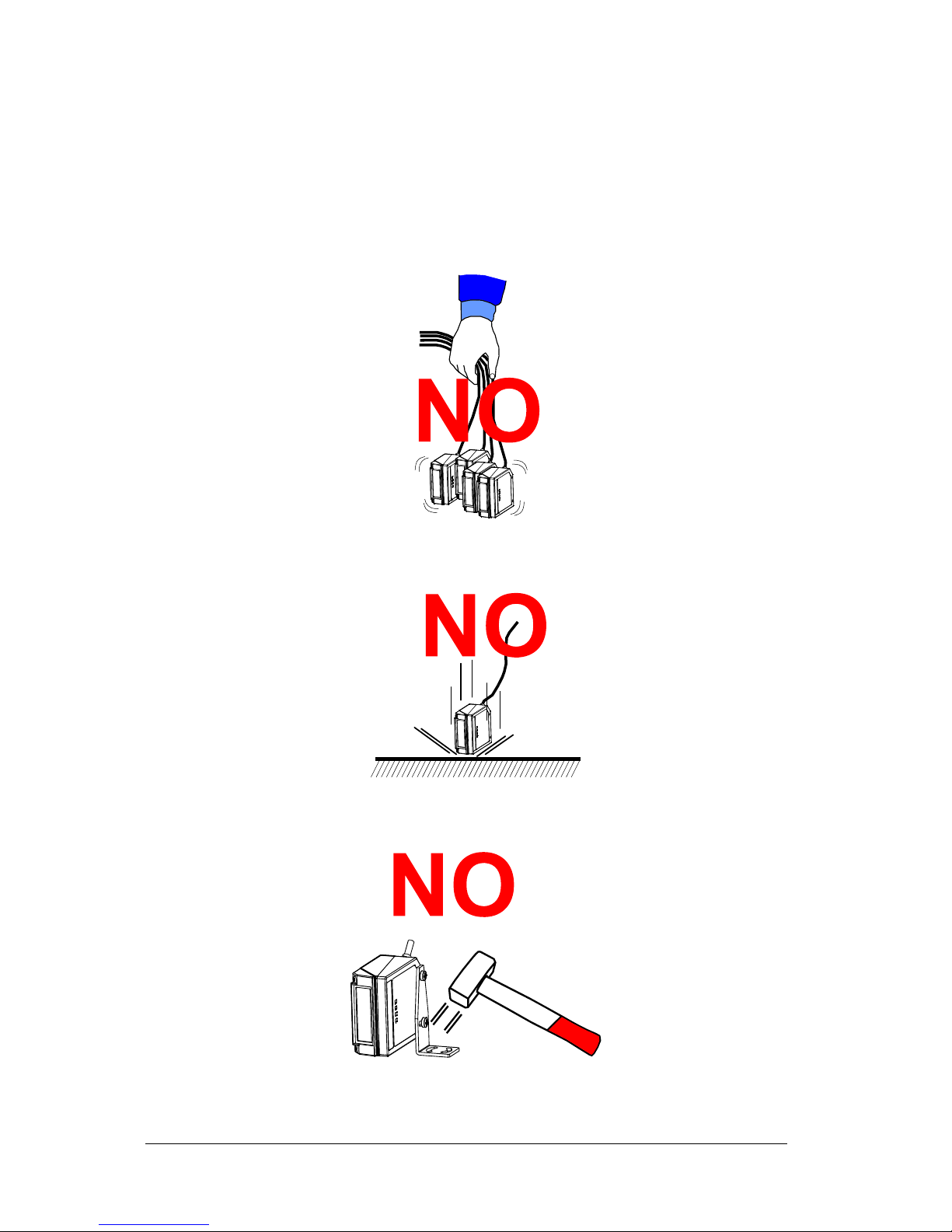
HANDLING
The TC1200 is designed to be used in an industrial environment and is built to withstand
vibration and shock when correctly installed, however it is also a precision product and
therefore before and during installation it must be handled correctly to avoid damage.
avoid that the scanners hit one another causing damage. They should be handled
separately.
avoid that the scanners are dropped (exceeding shock limits).
do not fine tune the positioning by striking the scanner or bracket.
Page 12
xii
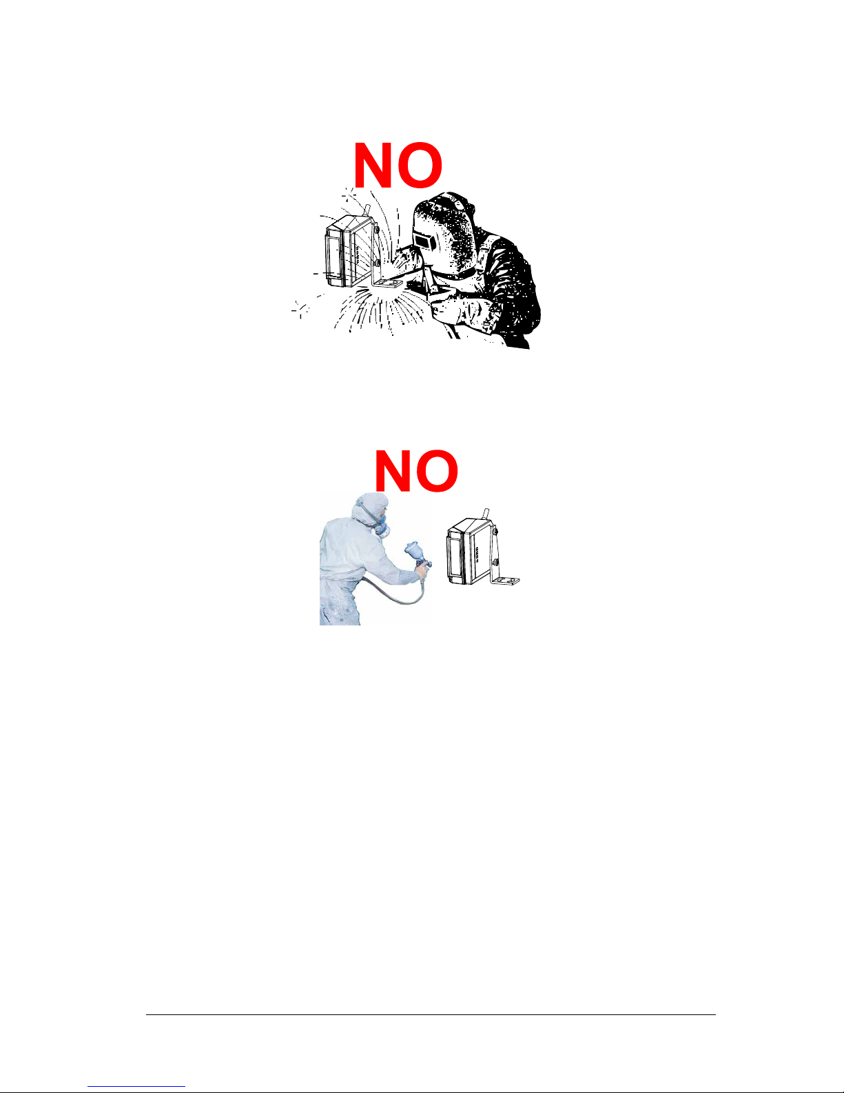
do not weld the scanner into position which can cause electrostatic, heat or output
window damage.
do not spray paint near the scanner which can cause output window damage.
Page 13

INTRODUCTION
1
1
1 INTRODUCTION
The TC1200 compact CCD reader is the perfect solution for many OEM applications. It
contains a built-in decoder
and multi-standard interface. Due to its well-balanced mix of
technical characteristics it is perfect for integration into custom equipment, setting a new
standard in this product class.
This Reference Manual provides connection diagrams, default parameter listing, complete
application parameter settings, specific technical features and reading diagrams.
1.1 CONFIGURATION METHODS
1.1.1 Configuration Using Datalogic Aladdin™
(for RS232/USB-COM Interfaces)
The easiest way to configure TC1200 is by using the Datalogic Aladdin™ utility program
downloadable from: www.automation.datalogic.com
.
Aladdin allows you to program the TC1200 reader by selecting configuration commands
through a user-friendly graphical interface running on a PC. These commands are sent to the
reader over the selected communication interface, or they can be printed as barcodes to be
scanned.
Aladdin also provides Help On-Line files explaining how to use the program as well as
descriptions of the configuration parameters.
Aladdin also provides the ability to perform a software upgrade for the connected device (see
the Datalogic Aladdin™ Help On-Line for more details).
1.1.2 Configuration Using Serial Programming Strings
(for RS232/USB-COM Interfaces)
This manual contains the complete
set of command strings for TC1200 configuration. These
strings can be sent via the RS232/USB-COM interface using a terminal emulator such as
HyperTerminal.
Refer to Chapter 3 of this manual for configuration procedures using Serial Strings sent by
the Host.
1.1.3 Configuration Using Programming Barcode Labels
(for all Interfaces)
Refer to Chapter 4 of this manual for configuration procedures using Programming Bacode
Labels.
Page 14
TC1200 REFERENCE MANUAL
2
1
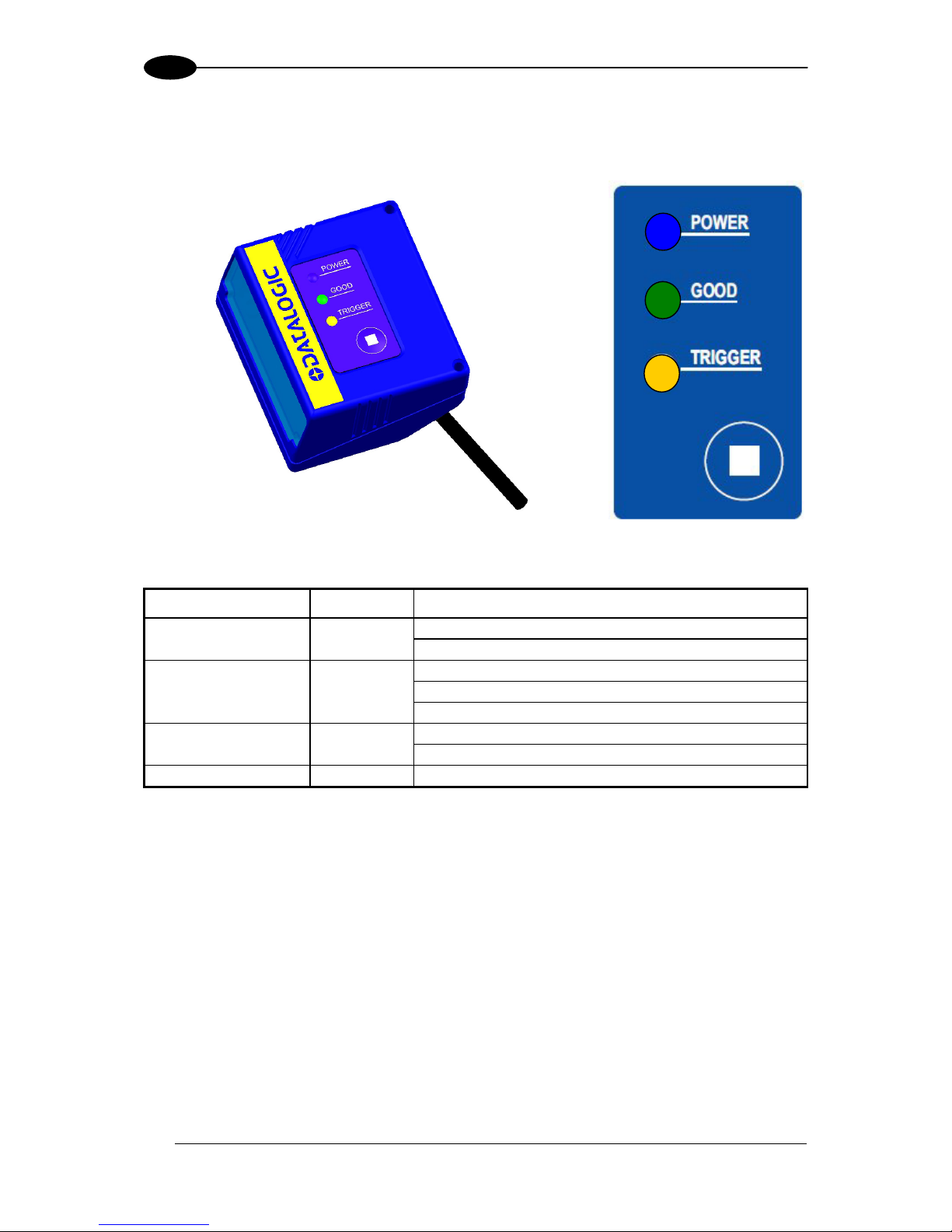
1.2 BUTTON AND LED INDICATORS
On the face of the TC1200 scanner a keypad is present with a button and three indicator
LEDs which are described in the table below.
TC1200 Scanner
TC1200 Keypad
INDICATORS Color MEANING
ON = Power ON POWER LED Blue
OFF = Power OFF or standby (only USB model)
ON = Good Read
OFF = No Read
GOOD Read LED Green
Blinks = USB enumeration
ON = External trigger or button pressed TRIGGER LED Yellow
OFF = No trigger
Button Press for manual trigger
1.3 AVAILABLE MODELS
The TC1200 reader is available in models that differ in regard to the following characteristics:
Output Interface
Enclosure
The following models are therefore available:
TC1200-1000 CCD Reader, RS232
TC1200-1100 CCD Reader, USB
TC1200-0000 Scan Engine CCD Reader, RS232
TC1200-0100 Scan Engine CCD Reader, USB
Page 15
INSTALLATION
3
2
2 INSTALLATION
2.1 TC1200 CCD SCANNER
2.1.1 Mechanical Installation
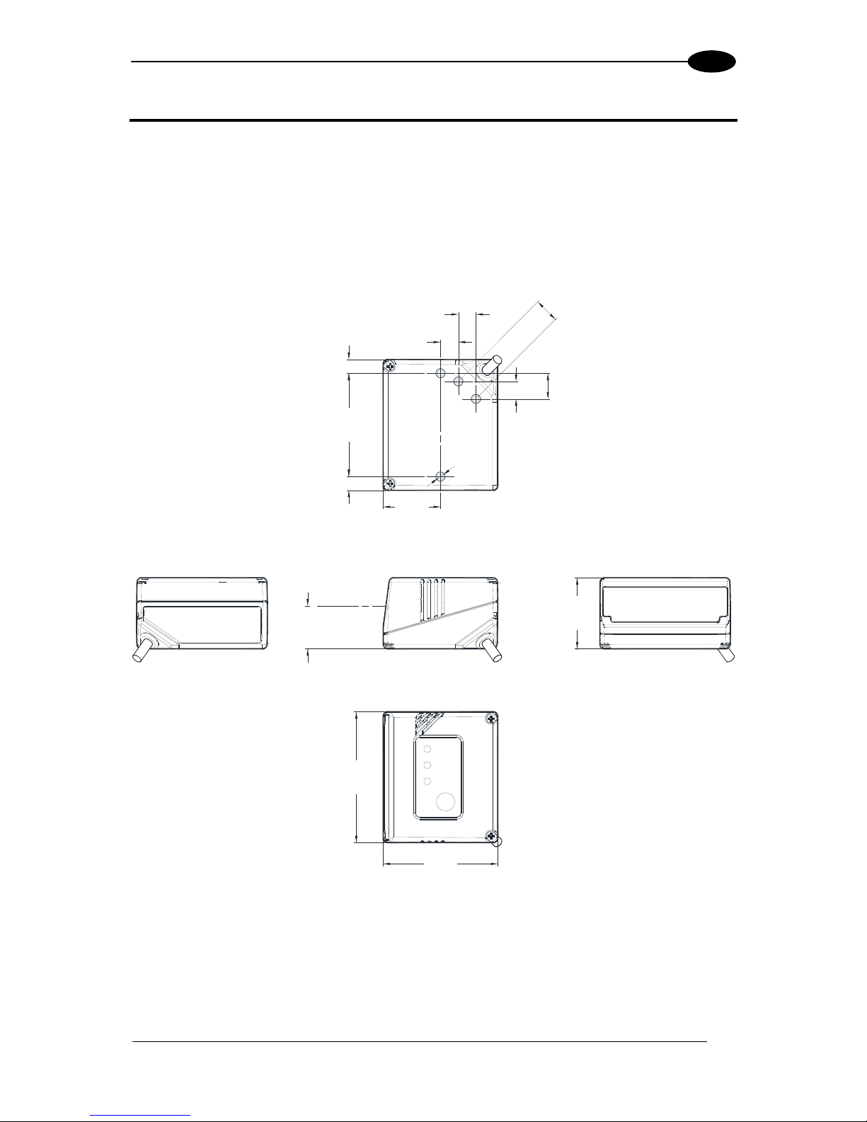
The diagram below gives the overall dimensions of the reader and may be used for its
installation.
57
[2.24]
50
[1.97]
31
[1.22]
18.7
[0.736]
25
[0.98]
45
[1.77]
6
[0.24]
6
[0.24]
8
[0.31]
11
[0.44]
8
[0.30]
8
[0.30]
11
[
0
.43]
MØ3
[Ø0.12] N°4
Figure 1 - Overall Dimensions
Optical Axis
Page 16
TC1200 REFERENCE MANUAL
4
2
2.1.2 Electrical Connections
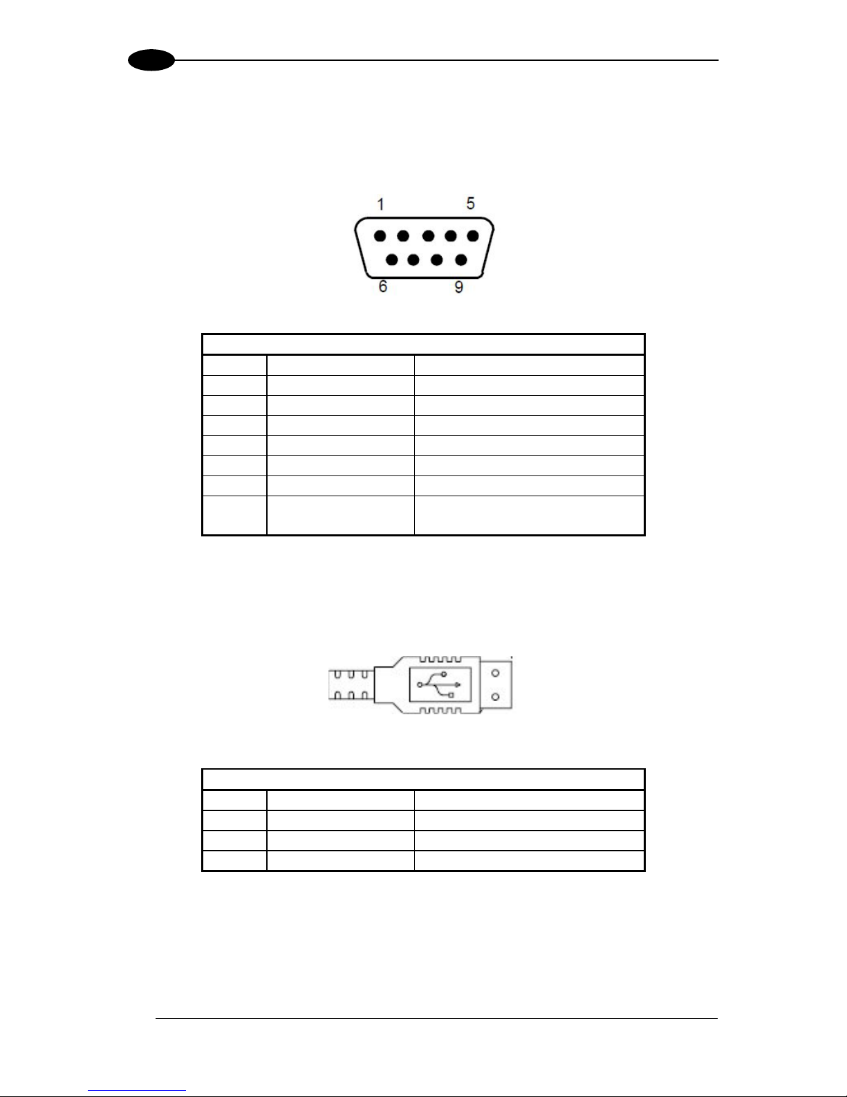
The TC1200-1000 Scanner is equipped with a 9-pin Male D-Sub connector for connection to
the power supply and input/output signals. The details of the connector pins are indicated in
the following table:
Figure 2 - 9-pin Male D-sub Connector
9-pin Connector
1 VCC +5Vdc
2 GND Ground
3 RX Receive Data
4 TX Transmit Data
5 OUT1 + Output signal 1, positive
6 OUT1/2 - Output signal 1/2, negative
7 OUT2 + Output signal 2, positive
8 EXT-TRIG + External Trigger Input, positive
9 EXT-TRIG - External Trigger Input, negative
Table 1 - TC1200-1000 Scanner Pinout
The TC1200-1100 Scanner is equipped with a USB Type A connector for connection to the
PC standard USB Port. The details of the connector pins are indicated in the following table:
Figure 3 – USB Type A Connector
USB Type A Connector
1 VCC +5 Vdc
2 DATA - USB Data, negative
3 DATA + USB Data, positive
4 GND Ground
Table 2 - TC1200-1100 Scanner Pinout
Page 17
INSTALLATION
5
2
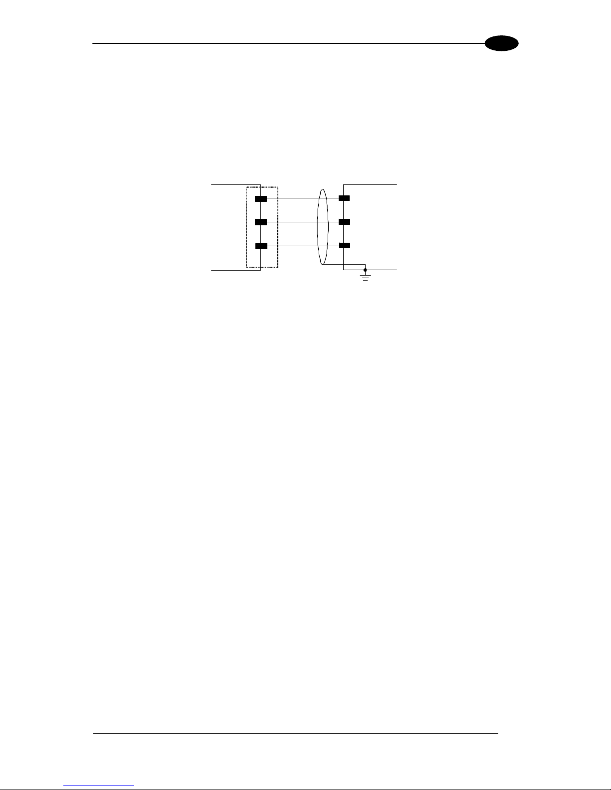
RS232 Interface
The TC1200-1000 Scanner can communicate with the Host using the RS232 signals
provided on the 9-pin connector. The pins are indicated in Table 1 and in the following
diagram:
It is a
lways advisable to use shielded cables. The overall maximum cable length must be
less than 15 m (49.2 ft).
TC1200 9-pin
2
3
G
ND
RX
TX
4
Host
GND
TXD
RXD
Earth
Ground
Figure 3 - RS232 Interface Connection to Host
Page 18
TC1200 REFERENCE MANUAL
6
2
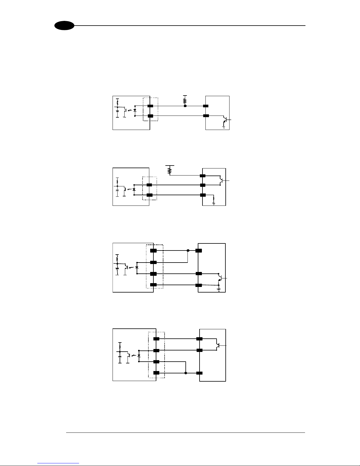
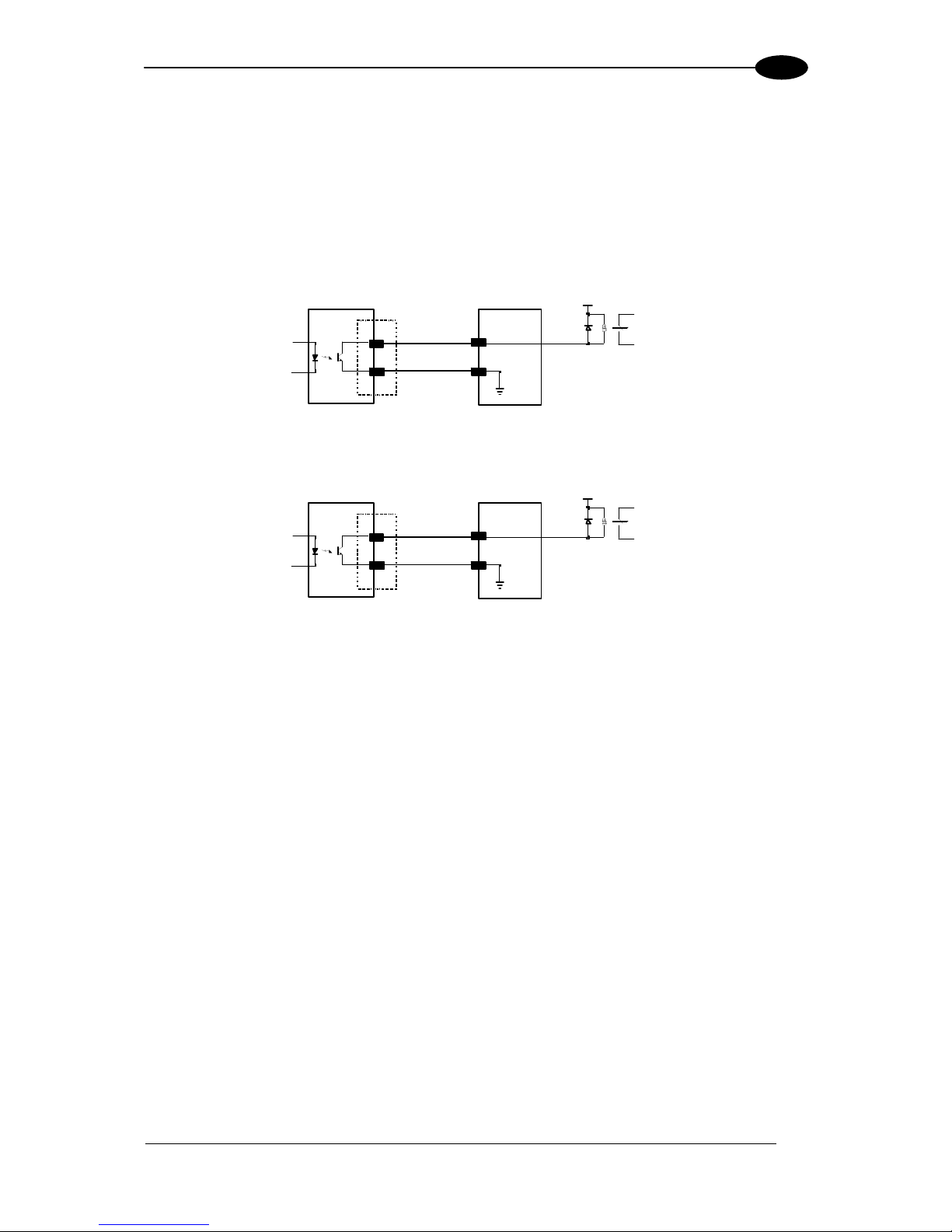
Inputs
There is an input available on the TC1200-1000 Scanner relative to the External Trigger
used to signal the reading phase for On Line Operating Mode. The pins are indicated in
Table 1. This input is optocoupled and can be dr
iven by both an NPN or PNP type command.
The connections are indicated in the following diagrams:
EXT TRIG+
8
9
+ 5V
TC1200
EXTERNAL TRIGGER
Signal
V
30 Vdc max.
V
ex t
EXT TR IG -
Figure 4 - Input NPN Command Using External Power
8
9
+ 5V
TC1200 EXTERNAL TRIGGER
30 Vdc max.Vext
V
Signal
Ground
EXT TRIG+
EXT TRIG-
Figure 5 - Input PNP Command Using External Power
EXTERNAL TRIGGERTC1200
Signal
8
9
+ 5V
1
2
GND
Ground
V
EXT TRIG+
EXT TRIG-
Vcc 5Vd c
Figure 6 - Input NPN Command Using TC1200 Power
EXTERNAL TRIGGERTC1200
8
9
+ 5V
Vc c 5V dc
1
2 GND
Ground
V
Sig nal
EXT TRIG+
EXT TRIG-
Figure 7 - Input PNP Command Using TC1200 Power
The External Trigger Input can also be activated by the external button (Push Button =
Trigger On).
Page 19
INSTALLATION
7
2
Outputs
There are two outputs available on the TC1200-1000 Scanner. Each output can be activated
on one of the following events: Good Read, No Read, Wrong Code.
The active level (high or low) of each Output can also be configured in software.
The pins are indicated in Table 1. The connections are indicated in the following diagram:
USER INTERFACE
Vext 30 Vdc ma x
OUT1 +
5
6 OUT1/2 -
TC1200
Figure 4 – Output1 Connection. Example NPN
USER INTERFACE
Vext 30 Vdc ma x
OUT2 +
7
6 OUT1/2 -
TC1200
Figure 9 – Output2 Connection. Example NPN
Page 20
TC1200 REFERENCE MANUAL
8
2
2.2 TC1200 CCD SCAN ENGINE
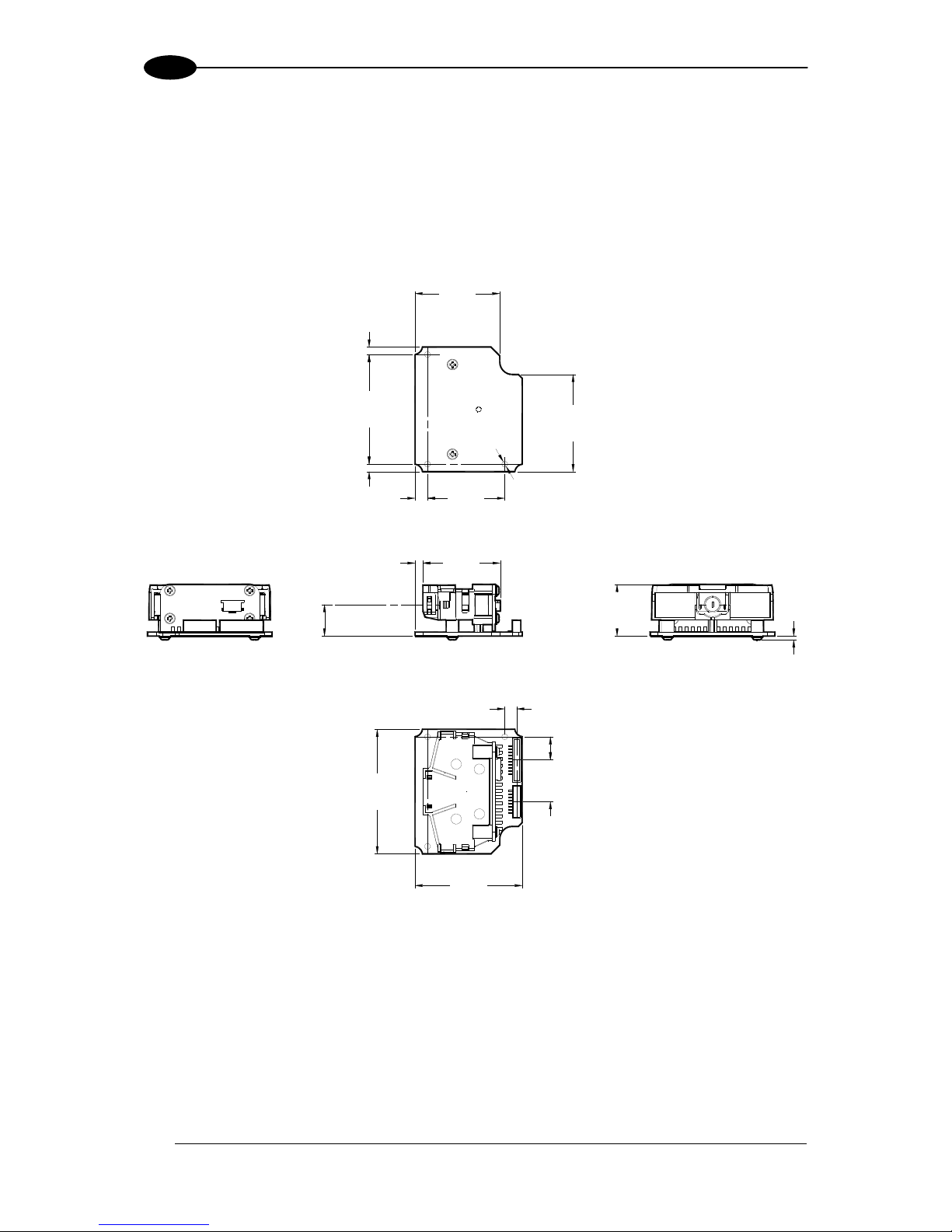
2.2.1 Mechanical Installation
The diagram below gives the overall dimensions of the TC1200 Scan Engine and may be
used for its installation.
50
[1.97]
43
[1.69]
20.8
[0.82]
12.7
[0.50]
5
[0.20]
44
[1.73]
3
[0.12]
3
[0.12]
31
[1.22]
1.5
[0.06]
4.8
[0.19]
9.3
[0.36]
16.8
[0.66]
34
[1.34]
39
[1.54]
Ø2.3
[Ø0.09] N°3
3.1
[0.12]
31.1
[1.22]
Figure 10 - Overall Dimensions
Optical Axis
Page 21

INSTALLATION
9
2
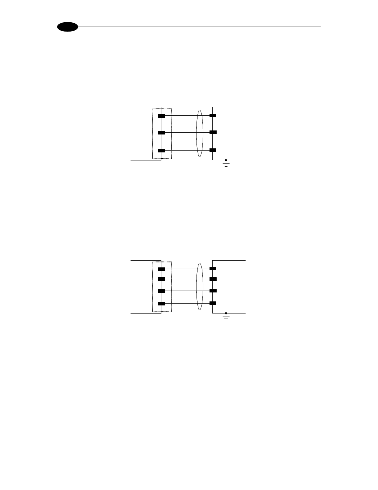
2.2.2 Electrical Connections
The TC1200-0X00 Scan Engine is equipped with an 8-pin and a 10-pin DF13 connector for
connection to the power supply and input/output signals. The details of the connector pins
are indicated in the following table:
Figure 5 – 10 and 8-pin Connectors
J1
Pin Signal Description
1 D- USB Data negative
2 D+ USB Data positive
3 GND power ground
4 GND power ground
5 TX transmit data
6 RTS NOT USED
7 RX receive data
8 CTS NOT USED
9 VCC +5Vdc
10 GND power ground
J2
Pin Signal Description
1 GND power ground
2 NC
3 OUT2+ Output 2 positive
4 OUT1/2- Output 1/2 negative
5 OUT1+ Output 1 positive
6 NC
7 EXT TRIG- External Trigger Input positive
8 EXT TRIG+ External Trigger Input negative
Table 3 - TC1200 Scan Engine Pinout
J1
J2
Page 22
TC1200 REFERENCE MANUAL
10
2
RS232 Interface
The TC1200-0000 Scan Engine can communicate with the Host using the RS232 signals
provided on the J1 connector. The pins are indicated in Table 1 and in the following diagram:
It is a
lways advisable to use shielded cables. The overall maximum cable length must be
less than 15 m (49.2 ft).
TC1200
10
7
GND
RX
TX
5
Host
GND
TXD
RXD
Earth
Ground
J1
Figure 12 - RS232 Interface Connection to Host
USB Interface
The TC1200-0100 Scan Engine can communicate with the Host using the USB signals
provided on the J1 connector. The pins are indicated in Table 1 and in the following diagram:
It is a
lways advisable to use shielded cables. The overall maximum cable length must be
less than 15 m (49.2 ft).
TC1200
10
2
GND
D+
D-
1
Host
GND
D+
D-
Earth
Ground
J1
9
VC C
VCC
Figure 13 - USB Interface Connection to Host
Page 23
INSTALLATION
11
2
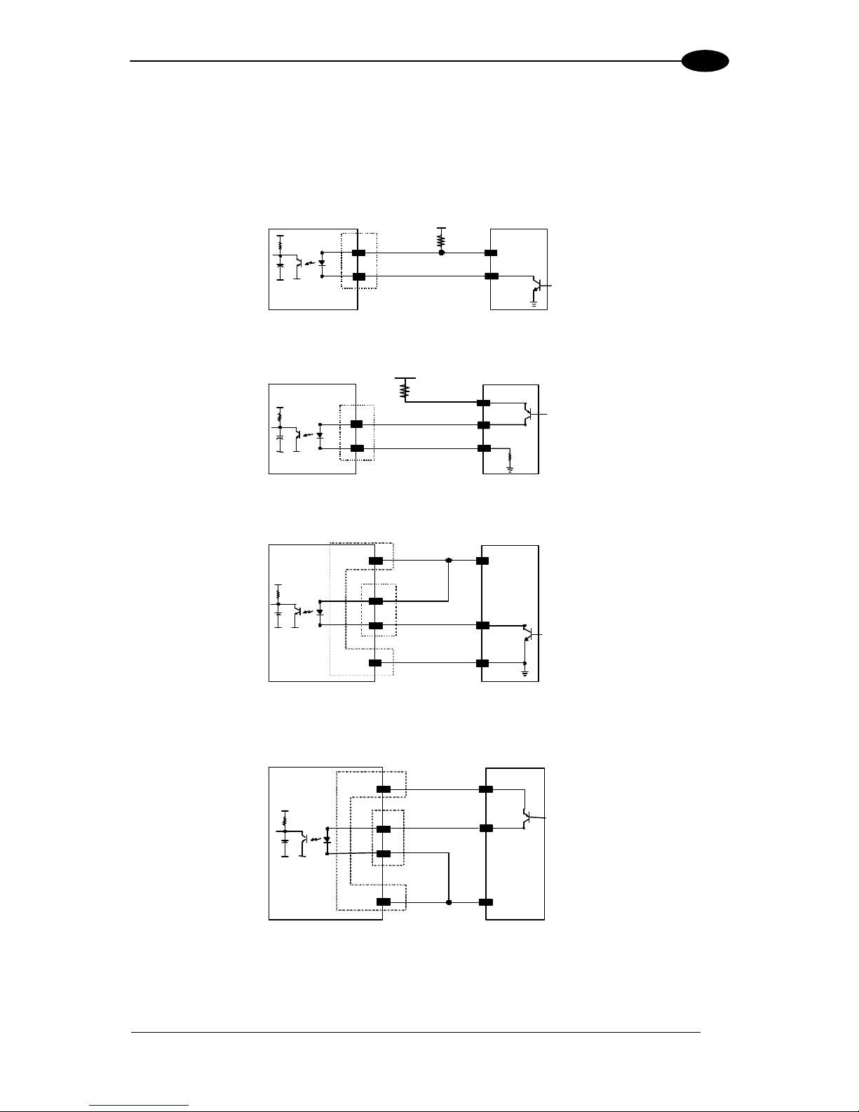
Inputs
There is an input available on the TC1200-0000 Scan Engine relative to the External Trigger
used to signal the reading phase for On Line Operating Mode. The pins are indicated in
Table 1. This input is optocoupled and can be dr
iven by both an NPN or PNP type command.
The connections are indicated in the following diagrams:
EXT TRIG+
8
7
+ 5V
TC1200
EXTERNAL TRIGGER
Signal
V
30 Vdc max.
V
ex t
EXT TR IG -
J2
Figure 14 - Input NPN Command Using External Power
8
7
+ 5V
TC1200 EXTERNAL TRIGGER
30 Vdc max.Vext
V
Signal
Ground
EXT TRIG+
EXT TRIG-
J2
Figure 15 - Input PNP Command Using External Power
J2
J1
8
7
9
10
GND
EXT TR IG +
EXT TRIG-
Vcc 5Vdc
EXTERNAL TRIGGERTC 12 00
Signal
+ 5V
Ground
V
Figure 15 - Input NPN Command Using TC1200 Power
J1
J2
Vcc 5Vdc
EXT TRIG+
EXTERNAL TRIGGERTC1200
8
7
9
V
Sig nal
EXT T RIG -
GND
Gro und
10
Figure 16 - Input PNP Command Using TC1200 Power
Page 24
TC1200 REFERENCE MANUAL
12
2
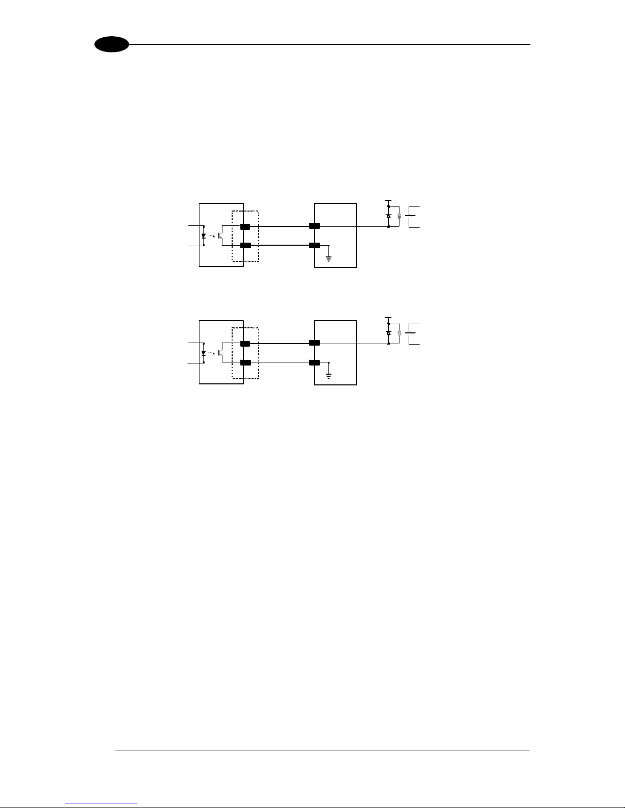
Outputs
There are two outputs available on the TC1200-0000 Scan Engine. Each output can be
activated on one of the following events: Good Read, No Read, Wrong Code.
The active level (high or low) of each Output can also be configured in software.
The pins are indicated in Table 1. The connections are indicated in the following diagram:
USER INTERFACE
Vext 30 Vdc ma x
OUT1 +
5
4 OUT1/2 -
TC1200
J2
Figure 17 – Output1 Connection. Example NPN
US E R IN TERF ACE
Vext 30 Vdc ma x
OUT2 +
3
4 OUT1/2 -
TC1200
J2
Figure 18 – Output2 Connection. Example NPN
Page 25
INSTALLATION
13
2
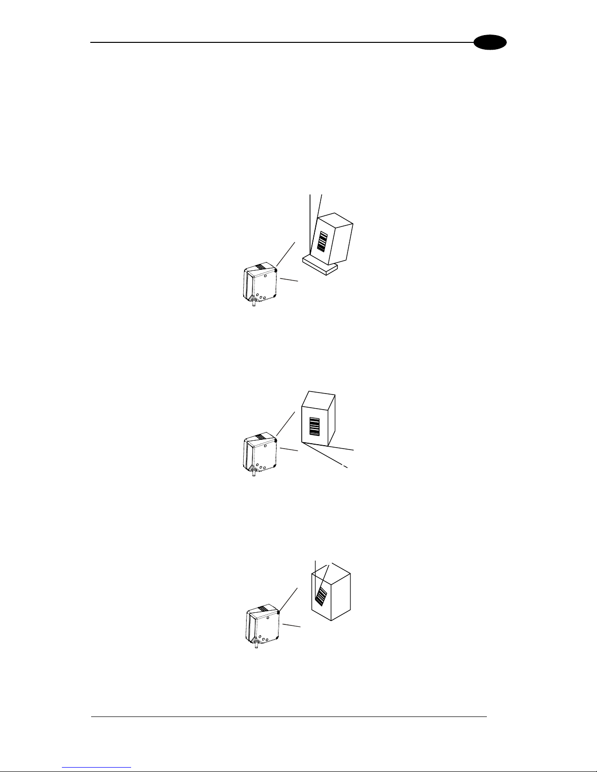
2.3 POSITIONING
The TC1200 Scanner is able to decode barcode labels at a variety of angles, however
significant angular distortion may degrade reading performance.
When mounting the TC1200 take into consideration these three ideal label position angles: Pitch
0°, Skew 10° to 30° and Tilt 0°. Follow the suggestions for the best orientation:
The Pitch angle is represented by the value P in the figure. Position the reader in order to
minimize the Pitch angle.
Figure 19 - Pitch Angle
The Skew angle is represented by the value S in the figure. Position the reader to assure at
least 10° for the Skew angle. This avoids direct light reflection.
Figure 20 - Skew angle
The Tilt angle is represented by the value T in the figure. Position the reader in order to
minimize the Tilt angle.
Figure 21 - Tilt angle
P
S
T
Page 26
TC1200 REFERENCE MANUAL
14
3
3 SOFTWARE CONFIGURATION STRINGS
3.1 TC1200 CONFIGURATION
TC1200 RS232 models (as well as USB models having the USB-COM Interface selected),
can be configured using the serial strings contained in this chapter:
To configure TC1200 RS232 models by using the configuration strings:
1) Connect your TC1200 to a PC RS232 port according to the information in chapter 2.
Set the PC
serial port to the TC1200 default RS232 communication parameters (see
Appendix A).
NOTE
To configure the reader using configuration strings, you must enter Service
Mode which automatically sets the reader communication to 115200
baudrate. You must therefore set the host accordingly for RS232
communications. Upon exiting Service Mode, the programmed baud rate
will be restored.
2) Using a Terminal Emulation Program, send the Restore Current Interface Default string
to the reader using the syntax described on the next page.
3) Send all the necessary command strings according to your application's requirements.
To configure TC1200 USB models (only for USB-COM Interface) by using the
configuration strings:
NOTE
USB models by default have the USB-KBD Interface selected and are
easily configured by reading the barcodes in chapter 4.
1) Download and install the USB-COM driver from the TC1200 product page at
www.automation.datalogic.com.
2) Connect your TC1200 to a PC USB port according to the information in chapter 2.
3) Change the interface to
USB-COM by reading the barcode below.
USB-COM
ËÄ$P,HA47,PmtÎ
4) Using a Terminal Emulation Program, send the Restore Current Interface Default
string to the reader using the syntax described on the next page.
5) Send all the necessary command strings according to your application's requirements.
Page 27

SOFTWARE CONFIGURATION STRINGS
15
3
Command Syntax
1. Enter Service (Serial String Programming) Mode
$S<CR>
This command automatically sets the reader communication to 115200 baudrate.
2. Send Command
Command
<CR> $
Parameter Value
Where:
Command:
Description
HAXX
Interface Selection
AA
Enable All Symbologies
AD
Disable All Symbologies
R
Reset Reader
CXXXXXX
Write Single Configuration Item to RAM
Parameter:
XXXX
A 4-character ASCII string
See Serial Configuration Strings Table
Value:
XX
A 2-character Hex string
See Serial Configuration Strings Table
3. Apply and Save Configuration to FLASH (permanent memory) and Exit Service Mode
$Ar<CR>
This command automatically returns to the programmed baudrate.
Page 28

TC1200 REFERENCE MANUAL
16
3
Example 1:
1. $S<CR>
Enter Service Mode
2. $CLFCA02<CR>
Write command "Convert to Lower Case" to current configuration
3. $Ar<CR>
Apply and Save Configuration to FLASH (permanent memory) and Exit Service
Mode.
Each configuration parameter setting removes the condition previously active for that
parameter.
Example 2:
1. $S<CR>
Enter Service Mode
2. $HA05<CR>
Select RS232 Interface
3. $Ar<CR>
Apply and Save Configuration to FLASH (permanent memory) and Exit Service
Mode.
Example 3:
1. $+$!<CR>
Read Application Software Release
Page 29

SOFTWARE CONFIGURATION STRINGS
17
3
SERIAL CONFIGURATION STRINGS
ENTER/EXIT CONFIGURATION COMMANDS
Description Command
Enter Service Mode (configuration) fixed 115200 Baud rate S
Exit Service Mode (configuration) return to programmed Baud rate s
Apply Configuration to RAM (temporary memory) and Exit Service Mode r01
Apply and Save Configuration to FLASH (permanent memory) and Exit Service Mode Ar
NOTE
To configure the reader using configuration strings, you must enter Service
Mode which automatically sets the reader communication to 115200
baudrate. You must therefore set the host accordingly for RS232
communications. Upon exiting Service Mode, the programmed baud rate
will be restored.
CONFIGURATION COMMANDS
Description Command
Write Single Configuration Item to RAM (temporary memory) Cxxxxxx
Read Single Configuration Item from RAM (temporary memory) cxxxx
Reset Reader R
Read Application Software Release (does not require Enter/Exit Service Mode) $+$!
Host Commands Obey CIFIH00
Host Commands Ignore CIFIH01
Enable all Symbologies AA
Disable all Symbologies AD
NOTE
To read a particular parameter setting from the reader, send the read
parameter command without any value. The reader will respond with its
currently configured value.
NOTE
The Read Application Software Release command is a direct command that
does not require entering Service Mode.
INTERFACE SELECTION COMMANDS
Description Command
Restore Custom Default Configuration HA00
RS232 HA05
USB-COM HA47
USB-KBD HA35
USB-KBD-ALT HA2B
USB KBD-APPLE HA2C
NOTE
The Interface Selection commands store and load the new interface type
with its factory defaults into the current configuration.
Page 30
TC1200 REFERENCE MANUAL
18
3
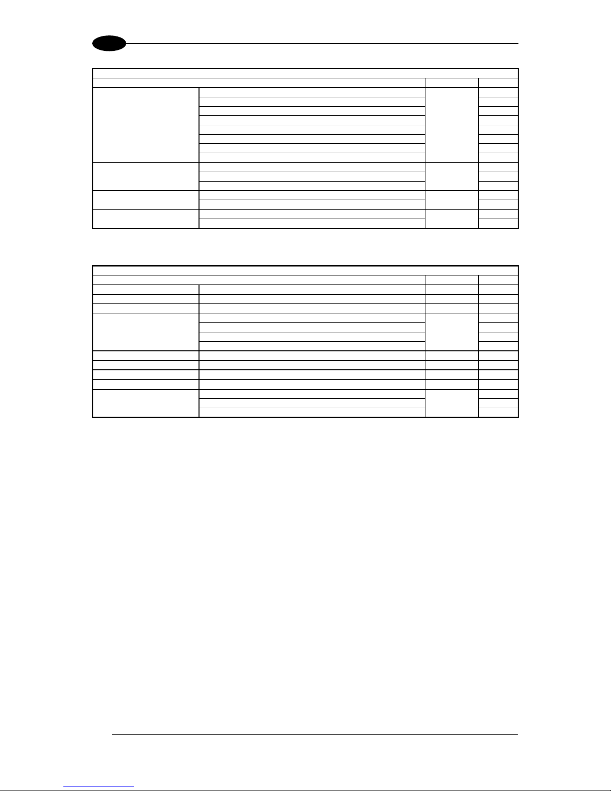
RS232 ONLY PARAMETERS
Description Parameter Value
Baud Rate 1200 R2BA 00
2400 01
4800 02
9600 03
19200 04
38400 05
57600 06
115200 07
Parity none R2PA 00
even 01
odd 02
Data Bits 7 R2DA 00
8 01
Stop Bits 1 R2ST 00
2 01
RS232/USB-COM PARAMETERS
Description Parameter Value
Intercharacter Delay No delay or from 10 to 990 ms R2IC a
Disable Character host command character which disables the reader R2DC b
Enable Character host command character which enables the reader R2EC b
ACK/NAK Options disable R2AE 00
enable for label transmission 01
enable for host command acknowledge 02
enable for label transmission and host command acknowledge 03
ACK Character Selects character to be used as ACK R2AC c
NAK Character Selects character to be used as NAK R2NA c
ACK/NAK Timeout Value No timeout or from 200 to 15000 ms R2AT d
ACK/NAK Retry Count From 0 to unlimited retries R2AR e
ACK/NAK Error Handling Ignore errors detected R2EH 00
Process errors as valid ACK character 01
Process errors as valid NAK character 02
a = Hex value from 00 to 63 representing the decimal number (00 = no delay; all others x10 ms)
b = Hex value from
00 to FE representing the ASCII character
c = Hex value from
00 to FF representing the ASCII character
d = Hex value from
00 to 4B representing the decimal number (00 = timeout disabled; all others x200 ms)
e = Hex value from
00 to FF representing the number of retries (00 = no retries; 01-FE = 1-254 retries; FF = unlimited retries)
Page 31

SOFTWARE CONFIGURATION STRINGS
19
3
USB-KBD / USB-KBD-ALT / USB-KBD-APPLE PARAMETERS
Description Parameter Value
Keyboard Country Mode *US KBCO 00
*Belgium 01
*Britain 02
Croatia 11
Czechoslovakia 0E
Denmark 03
*France 04
*Germany 05
Hungary 0D
*Italy 06
Japanese (106 key) 0C
Norway 07
Poland 12
Portugal 08
Romania 10
Slovakia 0F
*Spain 09
*Sweden 0A
Switzerland 0B
Keyboard Intercode Delay No delay or from 1 to 99 seconds KBID f
CTRL + KEY KBSC 00
CTRL + SHIFT + KEY 01
Send Control Characters
Special Function KEY
02
1 ms KBSP 01
2 ms 02
3 ms 03
4 ms 04
5 ms 05
6 ms 06
7 ms 07
8 ms 08
9 ms 09
USB Keyboard Speed
10 ms
0A
f = Hex value from 00 to 63 representing the decimal number (00 = no delay; all others x1 s)
* = Valid for USB-KBD-APPLE
READING PARAMETERS PARAMETERS
Description Parameter Value
Illumination Mode Disabled SPIL 00
Triggered 01
Enabled 02
Operating Modes On Line SNRM 00
Serial On Line 01
Automatic 02
Automatic (Object Sense) 03
Test 04
Automatic Threshold From 2 to 255 scans without a code SNAT g
Phase Off Event Trigger Stop SNTO 00
Timeout 01
Trigger Stop-Timeout 02
Timeout From 40 to 5100 ms SNET h
Serial Start Any string of characters (max 20) between 00-FE STON i
Serial Stop Any string of characters (max 20) between 00-FE STOF i
LED Indication On Decode BPIN 00
After Transmission 01
Label Programming Mode Disabled FAPM 00
Enabled 01
g = Hex value from 02 to FF representing the number of scans without a code
h = Hex value from
02 to FF representing the decimal number (x20 ms)
i = Hex value from
00 to FE representing the ASCII character
Page 32

TC1200 REFERENCE MANUAL
20
3
DATA FORMAT
Description Parameter Value
Data Transmission On Decode LFTX 01
After Phase Off 00
Code Verifier Mode Disabled LFCV 00
Transmit Wrong String 01
Transmit Wrong Code 02
Match String Any string of characters (max 20) between 00-FE COVS k
Wrong Code String Any string of characters (max 20) between 00-FE WCVS k
Case Conversion Disable LFCA 00
Upper Case 01
Lower Case 02
Global Prefix (Header) Any string of characters (max 20) between 00-FE LFPR k
Global Suffix (Terminator) Any string of characters (max 20) between 00-FE LFSU k
No Read String Any string of characters (max 20) between 00-FE NORS k
Character Conversion An 8-character string between 00-FF LFCH m
Transmit AIM IDs Disable AIEN 00
Enable 01
Transmit Custom Label IDs Disable IDCO 00
Prefix 01
Suffix 02
GS1-128 AIM ID Disable U8AI 00
Enable 01
k = Hex value from 00 to FE representing the ASCII character
m = 8 Hex values from
00 to FF representing the 8 ASCII characters (FF = no replacement or ignore)
Custom Code Identifiers Any string of characters (max 3) between 00-FE
UPC-A ABID k
UPC-E EBID k
EAN-8 8BID k
EAN-13 3BID k
UPC-A/P2 A2ID k
UPC-A/P5 A5ID k
UPC-E/P2 E2ID k
UPC-E/P5 E5ID k
EAN-8/P2 82ID k
EAN-8/P5 85ID k
EAN-13/P2 32ID k
EAN-13/P5 35ID k
ISBN ISID k
ISSN INID k
GTIN for EAN/UPC w/o Add-On GBID k
GTIN for EAN/UPC w P2 G2ID k
GTIN for EAN/UPC w P5 G5ID k
Code 39 C3ID k
Code 32 P3ID k
Code 128 C8ID k
GS1-128 U8ID k
ISBT 128 I8ID k
Interleaved 2 of 5 I2ID k
Standard 2 of 5 S2ID k
Codabar CBID k
ABC Codabar ACID k
Code 11 C1ID k
GS1 Databar 14 (Omnidirectional) 4BID k
GS1 Databar Expanded XBID k
GS1 Databar Limited LBID k
Code 93 C9ID k
MSI MSID k
k = Hex value from 00 to FE representing the ASCII character
Page 33

SOFTWARE CONFIGURATION STRINGS
21
3
DIGITAL OUTPUTS
Description Parameter Value
OUTPUT 1
Activation Event Disable OUA1 00
Good Read 01
No Read 02
Wrong Code 03
Deactivation Event Disable OUD1 00
Timeout 01
Reading Phase Active 02
Deactivation Timeout 100 to 25500 ms OUT1 n
Active Level Closed OUL1 00
Open 01
OUTPUT 2
Activation Event Disable OUA2 00
Good Read 01
No Read 02
Wrong Code 03
Deactivation Event Disable OUD2 00
Timeout 01
Reading Phase Active 02
Deactivation Timeout 100 to 25500 ms OUT2 n
Active Level Closed OUL2 00
Open 01
n = Hex value from 01 to FF representing the decimal number (x100 ms)
POWER SAVE
Description Parameter Value
Sleep Mode Timeout Disable SLTO 00
10 seconds 01
30 seconds 02
1 minute 03
5 minutes 04
10 minutes 05
Page 34

TC1200 REFERENCE MANUAL
22
3
CODE SELECTION
Description Parameter Value
UPC-A
UPC-A Disable ABEN 00
Enable 01
Check Character Tx Disable ABCT 00
Enable 01
Expand to EAN-13 Disable AB3B 00
Enable 01
Number System Tx Disable ABNS 00
Enable 01
Minimum Reads One Read ABMR 01
Two Reads 02
Three Reads 03
Four Reads 04
Coupon Control Allow all coupon barcodes to be decoded CPCL 00
Enable only UPC-A coupon decoding 01
Enable only GS1 Databar coupon decoding 02
UPC-E
UPC-E Disable EBEN 00
Enable 01
Check Character Tx Disable EBCT 00
Enable 01
Expand to UPC-A Disable EBAB 00
Enable 01
Expand to EAN-13 Disable EB3B 00
Enable 01
Number System Tx Disable EBNS 00
Enable 01
Minimum Reads One Read EBMR 01
Two Reads 02
Three Reads 03
Four Reads 04
EAN-13
EAN-13 Disable 3BEN 00
Enable 01
Check Character Tx Disable 3BCT 00
Enable 01
ISBN Conversion Disable 3BIS 00
Enable 01
ISSN Conversion Disable 3BIN 00
Enable 01
Flag 1 Character Disable 3BF1 00
Enable 01
Minimum Reads One Read 3BMR 01
Two Reads 02
Three Reads 03
Four Reads 04
Coupon Control Allow all coupon barcodes to be decoded CPCL 00
Enable only UPC-A coupon decoding 01
Enable only GS1 Databar coupon decoding 02
EAN-8
EAN-8 Disable 8BEN 00
Enable 01
Check Character Tx Disable 8BCT 00
Enable 01
Expand to EAN-13 Disable 8B3B 00
Enable 01
Minimum Reads One Read 8BMR 01
Two Reads 02
Three Reads 03
Four Reads 04
Page 35

SOFTWARE CONFIGURATION STRINGS
23
3
CODE SELECTION
Description Parameter Value
Add-Ons
P2 Add-On Disable ADO2 00
Enable 01
P5 Add-On Disable ADO5 00
Enable 01
P2 Minimum Reads One Read ADM2 01
Two Reads 02
Three Reads 03
Four Reads 04
P5 Minimum Reads One Read ADM5 01
Two Reads 02
Three Reads 03
Four Reads 04
Optional Add-On Timer Timer disabled or from 10 to 300 ms ADOT p
EAN/UPC Global Settings
GTIN Format Disable GBEN 00
Enable 01
Decoding Level Disable UNDL 00
Level 1 01
Level 2 02
Level 3 03
Level 4 04
Level 5 05
Character Correlation Disable UNCO 00
Enable 01
In-Store Minimum Reads One Read INMR 01
Two Reads 02
Three Reads 03
Four Reads 04
p = Hex value from 00 to 1E representing the decimal number (00 = Timer disabled; all others x10 ms)
Page 36

TC1200 REFERENCE MANUAL
24
3
CODE SELECTION
Description Parameter Value
Code 39
Code 39 Disable C3EN 00
Enable 01
Code 39 Full ASCII Disable C3FA 00
Enable 01
Code Length Control Variable C3LC 00
Fixed 01
Set Length Length 1 (or Min Length) from 1 to 50 characters C3L1 q
Length 2 (or Max Length) 0 or from 1 to 50 characters C3L2 q
Code 32 (Italian Pharma) Disable P3EN 00
Enable 01
Code 32 Check Tx Disable P3CT 00
Enable 01
Code 32 Start/Stop Tx Disable P3SS 00
Enable 01
Check Options
Check Calculation Disable C3CC 00
Enable Standard Check 01
Enable Mod-7 Check 02
Enable Italian Post Check 04
Enable Daimler Chrysler Check 08
Code 39 Check Tx Disable C3CT 00
Enable 01
Code 39 Start/Stop Tx Disable C3SS 00
Enable 01
Decoding Options
Minimum Reads One Read C3MR 01
Two Reads 02
Three Reads 03
Four Reads 04
Decoding Level Disable C3DL 00
Level 1 01
Level 2 02
Level 3 03
Level 4 04
Level 5 05
Interdigit Ratio Any ratio or 1 to 10 C3IR r
Character Correlation Disable C3CO 00
Enable 01
Quiet Zones Quiet Zone on One Side C3LO 01
Quiet Zones on Two Sides 02
Auto 03
Virtual Quiet Zones on Two Sides 04
Small Quiet Zones on Two Sides 05
Stitching Disable C3ST 00
Enable 01
q = Hex value from 00 to 32 representing the decimal number
r = Hex value from
00 to 0A representing the decimal number of the interdigit space/module ratio (00 = any ratio)
Page 37

SOFTWARE CONFIGURATION STRINGS
25
3
CODE SELECTION
Description Parameter Value
Code 128 (GS1-128)
Code 128 Disable C8EN 00
Enable 01
GS1-128 Enable Enable (transmit labels in Code 128 data format) U8EN 00
Enable (transmit labels in GS1-128 data format) 01
Disable 02
Code Length Control Variable C8LC 00
Fixed 01
Set Length Length 1 (or Min Length) from 1 to 80 characters C8L1 s
Length 2 (or Max Length) 0 or from 1 to 80 characters C8L2 s
Expand to Code 39 Disable C8C3 00
Enable 01
Check Options
Check Tx Disable C8CT 00
Enable 01
Function Character Tx Disable C8TF 00
Enable 01
Sub-Code Change Tx Disable C8SC 00
Enable 01
Decoding Options
Minimum Reads One Read C8MR 01
Two Reads 02
Three Reads 03
Four Reads 04
Decoding Level Disable C8DL 00
Level 1 01
Level 2 02
Level 3 03
Level 4 04
Level 5 05
Character Correlation Disable C8CO 00
Enable 01
Quiet Zones No Quiet Zones C8LO 00
Quiet Zone on One Side 01
Quiet Zones on Two Sides 02
Auto 03
Virtual Quiet Zones on Two Sides 04
Stitching Disable C8ST 00
Enable 01
ISBT 128
ISBT 128 Concatenation Disable I8CE 00
Enable 01
Concatenation Mode Static I8CM 00
Dynamic 01
Dynamic Concat. Timeout From 50 to 2550 ms I8DT t
Chain 0 - Chain 15 Contact Datalogic
s = Hex value from 00 to 50 representing the decimal number
t = Hex value from
05 to FF representing the decimal number (x10 ms)
Page 38

TC1200 REFERENCE MANUAL
26
3
CODE SELECTION
Description Parameter Value
Interleaved 2 of 5 (I 2 of 5)
I 2 of 5 Disable I2EN 00
Enable 01
Code Length Control Variable I2LC 00
Fixed 01
Set Length Length 1 (or Min Length) from 2 to 50 characters (only even numbers) I2L1 v
Length 2 (or Max Length) from 0 or from 2 to 50 characters (only even
numbers)
I2L2 v
Check Options
Check Calculation Disable I2CC 00
Enable Standard(Mod 10) 01
Enable German Parcel 02
Enable DHL 04
Enable Daimler Chrysler 08
Enable Bosch 10
Enable Italian Post 20
Check Tx Disable I2CT 00
Enable 01
Decoding Options
Minimum Reads One Read I2MR 01
Two Reads 02
Three Reads 03
Four Reads 04
Decoding Level Disable I2DL 00
Level 1 01
Level 2 02
Level 3 03
Level 4 04
Level 5 05
Character Correlation Disable I2CO 00
Enable 01
Stitching Disable I2ST 00
Enable 01
Zero Pattern Disable I2ZP 00
Enable 01
v = Hex value from 00 or 02 to 32 representing the decimal number
Standard 2 of 5
Standard 2 of 5 Disable S2EN 00
Enable 01
Code Length Control Variable S2LC 00
Fixed 01
Set Length Length 1 (or Min Length) from 1 to 50 characters S2L1 v
Length 2 (or Max Length) 0 or from 1 to 50 characters S2L2 v
Check Options
Check Calculation Disable S2CC 00
Enable 01
Check Tx Disable S2CT 00
Enable 01
Decoding Options
Minimum Reads One Read S2MR 01
Two Reads 02
Three Reads 03
Four Reads 04
Decoding Level Disable S2DL 00
Level 1 01
Level 2 02
Level 3 03
Level 4 04
Level 5 05
Character Correlation Disable S2CO 00
Enable 01
Stitching Disable S2ST 00
Enable 01
v = Hex value from 00 to 32 representing the decimal number
Page 39

SOFTWARE CONFIGURATION STRINGS
27
3
CODE SELECTION
Description Parameter Value
Codabar
Codabar Disable CBEN 00
Enable 01
Code Length Control Variable CBLC 00
Fixed 01
Set Length Length 1 (or Min Length) from 3 to 50 characters CBL1 v
Length 2 (or Max Length) 0 or from 3 to 50 characters CBL2 v
ABC Codabar
ABC Codabar Disable CBAB 00
Enable 01
Concatenation Mode Static CBCM 00
Dynamic 01
Dynamic Concat. Timeout From 50 to 2550 ms CBDT t
Check Options
Check Calculation Disable CBCC 00
Enable AIM Standard Check 01
Enable Mod-10 Check 02
Check Tx Disable CBCT 00
Enable 01
Start/Stop Set ABCD/TN*E CBSC 00
ABCD/ABCD 01
abcd/tn*e 02
abcd/abcd 03
Start/Stop Tx Disable CBSS 00
Enable 01
Start/Stop Match Disable CBSM 00
Enable 01
Decoding Options
Minimum Reads One Read CBMR 01
Two Reads 02
Three Reads 03
Four Reads 04
Decoding Level Disable CBDL 00
Level 1 01
Level 2 02
Level 3 03
Level 4 04
Level 5 05
Character Correlation Disable CBCO 00
Enable 01
Interdigit Ratio Any ratio or 1 to 10 CBIR r
Quiet Zones Quiet Zone on One Side CBLO 01
Quiet Zones on Two Sides 02
Auto 03
Virtual Quiet Zones on Two Sides 04
Small Quiet Zones on Two Sides 05
Stitching Disable CBST 00
Enable 01
v = Hex value from 00 or 03 to 32 representing the decimal number
t = Hex value from
05 to FF representing the decimal number (x10 ms)
r = Hex value from
00 to 0A representing the decimal number of the interdigit space/module ratio (00 = any ratio)
Page 40

TC1200 REFERENCE MANUAL
28
3
CODE SELECTION
Description Parameter Value
Code 11
Code 11 Disable C1EN 00
Enable 01
Code Length Control Variable C1LC 00
Fixed 01
Set Length Length 1 (or Min Length) from 2 to 50 characters C1L1 v
Length 2 (or Max Length) 0 or from 2 to 50 characters C1L2 v
Check Options
Check Calculation Disable C1CC 00
Enable Check C 01
Enable Check K 02
Enable Check C and K 03
Check Tx Disable C1CT 00
Enable 01
Decoding Options
Minimum Reads One Read C1MR 01
Two Reads 02
Three Reads 03
Four Reads 04
Decoding Level Disable C1DL 00
Level 1 01
Level 2 02
Level 3 03
Level 4 04
Level 5 05
Character Correlation Disable C1CO 00
Enable 01
Interdigit Ratio 1 to 10 C1IR r
Stitching Disable C1ST 00
Enable 01
v = Hex value from 00 to 32 representing the decimal number
r = Hex value from
00 to 0A representing the decimal number of the interdigit space/module ratio (00 = any ratio)
GS1 Databar Omnidirectional
GS1 Databar Omnidirectional Disable 4BEN 00
Enable 01
GS1-128 Emulation Disable 4BU8 00
Enable 01
Omnidirectional Decoding Options
Minimum Reads One Read 4BMR 01
Two Reads 02
Three Reads 03
Four Reads 04
GS1 Databar Expanded
GS1 Databar Expanded Disable XBEN 00
Enable 01
GS1-128 Emulation Disable XBU8 00
Enable 01
Code Length Control Variable XBLC 00
Fixed 01
Set Length Length 1 (or Min Length) from 1 to 74 characters XBL1 w
Length 2 (or Max Length) 0 or from 1 to 74 characters XBL2 w
Expanded Decoding Options
Minimum Reads One Read XBMR 01
Two Reads 02
Three Reads 03
Four Reads 04
Coupon Control Allow all coupon barcodes to be decoded CPCL 00
Enable only UPC-A coupon decoding 01
Enable only GS1 Databar coupon decoding 02
GS1 Databar Limited
GS1 Databar Limited Disable LBEN 00
Enable 01
GS1-128 Emulation Disable LBU8 00
Enable 01
Page 41

SOFTWARE CONFIGURATION STRINGS
29
3
w = Hex value from 00 to 4A representing the decimal number
CODE SELECTION
Description Parameter Value
GS1 Databar Limited (continued)
Limited Decoding Options
Minimum Reads One Read LBMR 01
Two Reads 02
Three Reads 03
Four Reads 04
Code 93
Code 93 Disable C9EN 00
Enable 01
Code Length Control Variable C9LC 00
Fixed 01
Set Length Length 1 (or Min Length) from 1 to 50 characters C9L1 v
Length 2 (or Max Length) 0 or from 1 to 50 characters C9L2 v
Check Options
Check Calculation Disable C9CC 00
Enable Check C 01
Enable Check K 02
Enable Check C and K 03
Check Tx Disable C9CT 00
Enable 01
Decoding Options
Minimum Reads One Read C9MR 01
Two Reads 02
Three Reads 03
Four Reads 04
Decoding Level Disable C9DL 00
Level 1 01
Level 2 02
Level 3 03
Level 4 04
Level 5 05
Character Correlation Disable C9CO 00
Enable 01
Quiet Zones No Quiet Zones C9LO 00
Quiet Zone on One Side 01
Quiet Zones on Two Sides 02
Auto 03
Virtual Quiet Zones on Two Sides 04
Stitching Disable C9ST 00
Enable 01
v = Hex value from 00 to 32 representing the decimal number
Page 42

TC1200 REFERENCE MANUAL
30
3
CODE SELECTION
Description Parameter Value
MSI
MSI Disable MSEN 00
Enable 01
Code Length Control Variable MSLC 00
Fixed 01
Set Length Length 1 (or Min Length) from 1 to 50 characters MSL1 v
Length 2 (or Max Length) 0 or from 1 to 50 characters MSL2 v
Check Options
Check Calculation Disable MSCC 00
Enable Mod 10 01
Enable Mod 11/10 02
Enable Mod 10/10 03
Check Tx Disable MSCT 00
Enable 01
Decoding Options
Minimum Reads One Read MSMR 01
Two Reads 02
Three Reads 03
Four Reads 04
Decoding Level Disable MSDL 00
Level 1 01
Level 2 02
Level 3 03
Level 4 04
Level 5 05
Stitching Disable MSST 00
Enable 01
v = Hex value from 00 to 32 representing the decimal number
Page 43

BARCODE CONFIGURATION
31
4
4 BARCODE CONFIGURATION
CAUTION
The Barcode Configuration is suggested when using USB-KBD
interfaces.
4.1 INITIAL SETUP
The following procedure allows preparing your TC1200 to read barcodes by using the default
settings.
RESTORE DEFAULT
1.
Read the restore factory default parameters code below.
Restore TC1200 Current Interface Default
ËÄ$P,HA00,PmÂÎ
INTERFACE SELECTION
2.
Read the interface selection code for your application.
Only RS232 Models
RS232
ËÄ$P,HA05,PmHÎ
Page 44

TC1200 REFERENCE MANUAL
32
4
Only USB Models
USB-COM
ËÄ$P,HA47,PmtÎ
USB-KBD
ËÄ$P,HA35,Pm]Î
USB-KBD-ALT
ËÄ$P,HA2B,PmWÎ
USB-KBD-APPLE
ËÄ$P,HA2C,Pm_Î
YOUR READER IS NOW READY TO READ BARCODES.
To change the default settings see par. 4.2.
Page 45

BARCODE CONFIGURATION
33
4
4.2 CHANGING DEFAULT SETTINGS
Once your reader is setup, you can change the default parameters to meet your application
needs. Refer to the preceding paragraph for initial configuration in order to set the default
values and select the interface for your application.
In this manual, the configuration parameters are divided into logical groups making it easy to
find the desired function based on its reference group.
The first three groups are for Standard Interface parameter configuration:
RS232
RS232/USB-COM
USB-KBD
The following parameter groups are common to all interface applications:
READING PARAMETERS control various operating modes and indicator status functioning.
DATA FORMAT parameters regard the messages sent to the Host system for all interfaces.
DIGITAL OUTPUTS manage the events controlling the two digital outputs.
POWER SAVE manages overall current consumption in the reading device.
CODE SELECTION parameters allow configuration of a personalized mix of codes, code
families and their options.
Page 46

Enter/Exit Configuration
GLOBAL INTERFACE
ËÄ$PmIÎ
34
GLOBAL INTERFACE FEATURES
Obey Host Commands
ËÄ$CIFIH00mgÎ
Ignore Host Commands
ËÄ$CIFIH01mpÎ
Page 47

35
RS232
B
AUD RATE
P
ARITY
D
ATA BITS
S
TOP BITS
1. Read the Enter/Exit Configuration code ONCE, available at the top of each page.
2. Read configuration codes from the desired groups.
= Read the code and follow the procedure on the indicated reference page
= Default value
3. Read the Enter/Exit Configuration code ONCE, available at the top of each page.
Page 48

Enter/Exit Configuration
RS232
ËÄ$PmIÎ
36
BAUD RATE
1200 baud
ËÄ$CR2BA00m3Î
2400 baud
4800 baud
ËÄ$CR2BA01m<Î
ËÄ$CR2BA02mEÎ
9600 baud
19200 baud
ËÄ$CR2BA03mNÎ
ËÄ$CR2BA04mWÎ
38400 baud
57600 baud
ËÄ$CR2BA05m`Î
ËÄ$CR2BA06miÎ
115200 baud
ËÄ$CR2BA07mrÎ
PARITY
none
ËÄ$CR2PA00mÂÎ
even
odd
ËÄ$CR2PA01m)Î
ËÄ$CR2PA02m2Î
Page 49

Enter/Exit Configuration
ËÄ$PmIÎ
RS232
37
DATA BITS
7 bits
ËÄ$CR2DA00m?Î
8 bits
ËÄ$CR2DA01mHÎ
STOP BITS
1 stop bit
ËÄ$CR2ST00mPÎ
2 stop bits
ËÄ$CR2ST01mYÎ
Page 50

38
RS232/USB-COM
I
NTERCHARACTER DELAY
D
ISABLE CHARACTER
E
NABLE CHARACTER
ACK/NAK
OPTIONS
ACK
CHARACTER
NAK
CHARACTER
ACK/NAK
TIMEOUT
ACK/NAK
RETRY COUNT
ACK/NAK
ERROR HANDLING
1. Read the Enter/Exit Configuration code ONCE, available at the top of each page.
2. Read configuration codes from the desired groups.
= Read the code and follow the procedure on the indicated reference page
= Default value
3. Read the Enter/Exit Configuration code ONCE, available at the top of each page.
Page 51

Enter/Exit Configuration
ËÄ$PmIÎ
RS232/USB-COM
39
INTERCHARACTER DELAY
No Delay
ËÄ$CR2IC00mkÎ
Select Intercharacter Delay
See page 114
ÌÄ$CR2IC`Î
DISABLE CHARACTER
Select Device Disable Character
ÌÄ$CR2DCBÎ
See page 114
ENABLE CHARACTER
Select Device Enable Character
ÌÄ$CR2ECHÎ
See page 115
ACK/NAK OPTIONS
Disable
ËÄ$CR2AE00mIÎ
Enable For Label Transmission
Enable For Host Command
Acknowledge
ËÄ$CR2AE01mRÎ
ËÄ$CR2AE02m[Î
Enable For Label Transmission
And Host Command
Acknowledge
ËÄ$CR2AE03mdÎ
ACK CHARACTER
Select ACK Character
ÌÄ$CR2AC0Î
See page 116
Page 52

Enter/Exit Configuration
RS232/USB-COM
ËÄ$PmIÎ
40
NAK CHARACTER
Select NAK Character
ÌÄ$CR2NApÎ
See page 116
ACK/NAK TIMEOUT
No Timeout
ËÄ$CR2AT00mKÎ
Select ACK/NAK Timeout Value
See page 117
ÌÄ$CR2AT@Î
ACK/NAK RETRY COUNT
Select Retry Count
ÌÄ$CR2AR2Î
See page 117
ACK/NAK ERROR HANDLING
Ignore Errors Detected
ËÄ$CR2EH00mvÎ
Process Errors As Valid ACK
Character
Process Errors As Valid NAK
Character
ËÄ$CR2EH01mÃÎ
ËÄ$CR2EH02m!Î
Page 53

41
USB-KBD
K
EYBOARD COUNTRY
C
APS LOCK
N
UM LOCK
I
NTER-CHARACTER DELAY
I
NTER-CODE DELAY
K
EYBOARD SETTING
C
ONTROL CHARACTER EMULATION
1. Read the Enter/Exit Configuration code ONCE, available at the top of each page.
2. Read configuration codes from the desired groups.
= Read the code and follow the procedure on the indicated reference page
= Default value
3. Read the Enter/Exit Configuration code ONCE, available at the top of each page.
Page 54

Enter/Exit Configuration
USB-KBD
ËÄ$PmIÎ
42
KEYBOARD COUNTRY
US
ËÄ$CKBCO00mhÎ
Belgium
Britain
ËÄ$CKBCO01mqÎ
ËÄ$CKBCO02mzÎ
Croatia
Czech Repubblic
ËÄ$CKBCO11myÎ
ËÄ$CKBCO0EmWÎ
Denmark
France
ËÄ$CKBCO03mÇÎ
ËÄ$CKBCO04m%Î
Germany
Hungary
ËÄ$CKBCO05m.Î
ËÄ$CKBCO0DmNÎ
Italy
Japanese (106 key)
ËÄ$CKBCO06m7Î
ËÄ$CKBCO0CmEÎ
Norway
ËÄ$CKBCO07m@Î
Page 55

Enter/Exit Configuration
ËÄ$PmIÎ
USB-KBD
43
KEYBOARD COUNTRY (CONTINUED)
Poland
ËÄ$CKBCO12mÆÎ
Portugal
Romania
ËÄ$CKBCO08mIÎ
ËÄ$CKBCO10mpÎ
Slovakia
Spain
ËÄ$CKBCO0Fm`Î
ËÄ$CKBCO09mRÎ
Sweden
Switzerland
ËÄ$CKBCO0Am3Î
ËÄ$CKBCO0Bm<Î
KEYBOARD INTERCODE DELAY
No Delay
ËÄ$CKBID00m?Î
Select Intercode Delay
See page 118
ÌÄ$CKBID4Î
Page 56

Enter/Exit Configuration
USB-KBD
ËÄ$PmIÎ
44
SEND CONTROL CHARACTERS
CTRL + Key
ËÄ$CKBSC00mtÎ
CTRL + SHIFT + Key
Special Function Key
ËÄ$CKBSC01m}Î
ËÄ$CKBSC02mÊÎ
USB KEYBOARD SPEED
1 ms
ËÄ$CKBSP01mqÎ
2 ms
3 ms
ËÄ$CKBSP02mzÎ
ËÄ$CKBSP03mÇÎ
4 ms
5 ms
ËÄ$CKBSP04m%Î
ËÄ$CKBSP05m.Î
6 ms
7 ms
ËÄ$CKBSP06m7Î
ËÄ$CKBSP07m@Î
8 ms
ËÄ$CKBSP08mIÎ
Page 57

Enter/Exit Configuration
ËÄ$PmIÎ
USB-KBD
45
USB KEYBOARD SPEED (CONTINUED)
9 ms
ËÄ$CKBSP09mRÎ
10 ms
ËÄ$CKBSP0Am3Î
Page 58

46
READING PARAMETERS
I
LLUMINATION MODE
O
PERATING MODE
A
UTOMATIC THRESHOLD
P
HASE OFF EVENT
T
IMEOUT
S
ERIAL START
S
ERIAL STOP
LED
INDICATION
L
ABEL PROGRAMMING MODE
1. Read the Enter/Exit Configuration code ONCE, available at the top of each page.
2. Read configuration codes from the desired groups.
= Read the code and follow the procedure on the indicated reference page
= Default value
3. Read the Enter/Exit Configuration code ONCE, available at the top of each page.
Page 59

Enter/Exit Configuration
ËÄ$PmIÎ
READING PARAMETERS
47
ILLUMINATION MODE
Disabled
ËÄ$CSPIL00mvÎ
Triggered
Enabled
ËÄ$CSPIL01mÃÎ
ËÄ$CSPIL02m!Î
OPERATING MODE
On Line
ËÄ$CSNRM00mBÎ
Serial On Line
Automatic
ËÄ$CSNRM01mKÎ
ËÄ$CSNRM02mTÎ
Automatic (Object Sense)
Test
ËÄ$CSNRM03m]Î
ËÄ$CSNRM04mfÎ
AUTOMATIC THRESHOLD
Select Automatic Threshold
ÌÄ$CSNATiÎ
See page 119
Page 60

Enter/Exit Configuration
READING PARAMETERS
ËÄ$PmIÎ
48
PHASE OFF EVENT
Trigger Stop
ËÄ$CSNTO00m\Î
Timeout
Trigger Stop - Timeout
ËÄ$CSNTO01meÎ
ËÄ$CSNTO02mnÎ
TIMEOUT
Select Timeout
ÌÄ$CSNETÅÎ
See page 120
SERIAL START
Select Serial Start Characters
ÌÄ$CSTONJÎ
See page 121
SERIAL STOP
Select Serial Stop Characters
ÌÄ$CSTOFyÎ
See page 121
LED INDICATION
On Decode
ËÄ$CBPIN00m@Î
After Transmission
ËÄ$CBPIN01mIÎ
Page 61

Enter/Exit Configuration
ËÄ$PmIÎ
READING PARAMETERS
49
LABEL PROGRAMMING MODE
Disabled
ËÄ$CFAPM00m(Î
Enabled
ËÄ$CFAPM01m1Î
Page 62

50
DATA FORMAT
D
ATA TRANSMISSION
C
ODE VERIFIER MODE
M
ATCH STRING
W
RONG CODE STRING
C
ASE CONVERSION
G
LOBAL PREFIX
G
LOBAL SUFFIX
N
O READ STRING
T
RANSMIT AIM IDS
T
RANSMIT CUSTOM LABEL IDS
C
USTOM LABEL IDS
1. Read the Enter/Exit Configuration code ONCE, available at the top of each page.
2. Read configuration codes from the desired groups.
= Read the code and follow the procedure on the indicated reference page
= Default value
3. Read the Enter/Exit Configuration code ONCE, available at the top of each page.
Page 63

Enter/Exit Configuration
ËÄ$PmIÎ
DATA FORMAT
51
DATA TRANSMISSION
On Decode
ËÄ$CLFTX01m`Î
After Phase Off
ËÄ$CLFTX00mWÎ
CODE VERIFIER MODE
Disabled
ËÄ$CLFCV00mJÎ
Transmit Wrong String
Transmit Wrong Code
ËÄ$CLFCV01mSÎ
ËÄ$CLFCV02m\Î
MATCH STRING
Select Match String
ÌÄ$CCOVS>Î
See page 129
WRONG CODE STRING
Select Wrong Code String
ÌÄ$CWCVSRÎ
See page 129
Page 64

Enter/Exit Configuration
DATA FORMAT
ËÄ$PmIÎ
52
CASE CONVERSION
Disable (no case conversion)
ËÄ$CLFCA00mÉÎ
Convert To Upper Case
Convert To Lower Case
ËÄ$CLFCA01m'Î
ËÄ$CLFCA02m0Î
GLOBAL PREFIX
Select Global Prefix (Header)
ÌÄ$CLFPRqÎ
See page 124
GLOBAL SUFFIX
Select Global Suffix (Terminator)
ÌÄ$CLFSU1Î
See page 124
NO READ STRING
Select No Read String
ÌÄ$CNORSRÎ
See page 125
Page 65

Enter/Exit Configuration
ËÄ$PmIÎ
DATA FORMAT
53
TRANSMIT AIM IDS
Disable
ËÄ$CAIEN00mhÎ
Enable
ËÄ$CAIEN01mqÎ
TRANSMIT CUSTOM LABEL IDS
Disabled
ËÄ$CIDCO00mjÎ
Prefix
Suffix
ËÄ$CIDCO01msÎ
ËÄ$CIDCO02m|Î
CUSTOM LABEL IDENTIFIERS
Set UPC-A Label ID(s)
ÌÄ$CABIDsÎ
See page 127
Set UPC-E Label ID(s)
Set EAN-8 Label ID(s)
See page 127
ÌÄ$CEBIDÇÎ
ÌÄ$C8BIDOÎ
See page 127
Set EAN-13 Label ID(s)
See page 127
ÌÄ$C3BID;Î
Page 66

Enter/Exit Configuration
DATA FORMAT
ËÄ$PmIÎ
54
CUSTOM LABEL IDENTIFIERS (CONTINUED)
Set UPC-A/P2 Label ID(s)
ÌÄ$CA2ID#Î
See page 127
Set UPC-A/P5 Label ID(s)
Set UPC-E/P2 Label ID(s)
See page 127
ÌÄ$CA5ID2Î
ÌÄ$CE2ID3Î
See page 127
Set UPC-E/P5 Label ID(s)
Set EAN-8/P2 Label ID(s)
See page 127
ÌÄ$CE5IDBÎ
ÌÄ$C82IDfÎ
See page 127
Set EAN-8/P5 Label ID(s)
Set EAN-13/P2 Label ID(s)
See page 127
ÌÄ$C85IDuÎ
ÌÄ$C32IDRÎ
See page 127
Set EAN-13/P5 Label ID(s)
Set ISBN Label ID(s)
See page 127
ÌÄ$C35IDaÎ
ÌÄ$CISIDÅÎ
See page 127
Set ISSN Label ID(s)
See page 127
ÌÄ$CINIDhÎ
Page 67

Enter/Exit Configuration
ËÄ$PmIÎ
DATA FORMAT
55
CUSTOM LABEL IDENTIFIERS (CONTINUED)
Set GTIN Label ID(s) for EAN/UPC
without Add-Ons
ÌÄ$CGBID$Î
See page 127
Set GTIN Label ID(s) for EAN/UPC
with P2
Set GTIN Label ID(s) for EAN/UPC
with P5
See page 127
ÌÄ$CG2ID;Î
ÌÄ$CG5IDJÎ
See page 127
Set Code 39 Label ID(s)
Set Code 32 Label ID(s)
See page 127
ÌÄ$CC3ID0Î
ÌÄ$CP3IDdÎ
See page 127
Set Code 128 Label ID(s)
Set GS1-128 Label ID(s)
See page 127
ÌÄ$CC8IDIÎ
ÌÄ$CU8ID*Î
See page 127
Set ISBT 128 Label ID(s)
Set Interleaved 2 of 5 Label ID(s)
See page 127
ÌÄ$CI8IDaÎ
ÌÄ$CI2IDCÎ
See page 127
Set Standard 2 of 5 Label ID(s)
Set Codabar Label ID(s)
See page 127
ÌÄ$CS2IDkÎ
ÌÄ$CCBID{Î
See page 127
Set ABC Codabar Label ID(s)
See page 127
ÌÄ$CACIDxÎ
Page 68

Enter/Exit Configuration
DATA FORMAT
ËÄ$PmIÎ
56
CUSTOM CODE IDENTIFIERS (CONTINUED)
Set Code 11 Label ID(s)
ÌÄ$CC1ID&Î
See page 127
Set Label ID(s) for GS1 Databar 14
(Omnidirectional)
Set Label ID(s) for GS1 Databar
Expanded
See page 127
ÌÄ$C4BID?Î
ÌÄ$CXBIDhÎ
See page 127
Set Label ID(s) for GS1 Databar
Limited
Set Code 93 Label ID(s)
See page 127
ÌÄ$CLBID8Î
ÌÄ$CC9IDNÎ
See page 127
Set MSI Label ID(s)
See page 127
ÌÄ$CMSID*Î
Page 69

57
DIGITAL OUTPUTS
O
UTPUT 1 ACTIVATION EVENT
O
UTPUT 1 DEACTIVATION EVENT
O
UTPUT 1 DEACTIVATION TIMEOUT
O
UTPUT 1 ACTIVE LEVEL
O
UTPUT 2 ACTIVATION EVENT
O
UTPUT 2 DEACTIVATION EVENT
O
UTPUT 2 DEACTIVATION TIMEOUT
O
UTPUT 2 ACTIVE LEVEL
1. Read the Enter/Exit Configuration code ONCE, available at the top of each page.
2. Read configuration codes from the desired groups.
= Read the code and follow the procedure on the indicated reference page
= Default value
3. Read the Enter/Exit Configuration code ONCE, available at the top of each page.
Page 70

Enter/Exit Configuration
DIGITAL OUTPUTS
ËÄ$PmIÎ
58
OUTPUT 1 ACTIVATION EVENT
Disable
ËÄ$COUA100m`Î
Good Read
No Read
ËÄ$COUA101miÎ
ËÄ$COUA102mrÎ
Wrong Code
ËÄ$COUA103m{Î
OUTPUT 1 DEACTIVATION EVENT
Disable
ËÄ$COUD100mrÎ
Timeout
Reading Phase Active
ËÄ$COUD101m{Î
ËÄ$COUD102mÈÎ
OUTPUT 1 DEACTIVATION TIMEOUT
Set Deactivation Timeout
ÌÄ$COUT1`Î
See page 130
OUTPUT 1 ACTIVATION EVENT
Closed
ËÄ$COUL100m;Î
Open
ËÄ$COUL101mDÎ
Page 71

Enter/Exit Configuration
ËÄ$PmIÎ
DIGITAL OUTPUTS
59
OUTPUT 2 ACTIVATION EVENT
Disable
ËÄ$COUA200mgÎ
Good Read
No Read
ËÄ$COUA201mpÎ
ËÄ$COUA202myÎ
Wrong Code
ËÄ$COUA203mÆÎ
OUTPUT 2 DEACTIVATION EVENT
Disable
ËÄ$COUD200myÎ
Timeout
Reading Phase Active
ËÄ$COUD201mÆÎ
ËÄ$COUD202m$Î
OUTPUT 2 DEACTIVATION TIMEOUT
Set Deactivation Timeout
ÌÄ$COUT2gÎ
See page 130
OUTPUT 2 ACTIVATION EVENT
Closed
ËÄ$COUL200mBÎ
Open
ËÄ$COUL201mKÎ
Page 72

60
POWER SAVE
S
LEEP MODE TIMEOUT
1. Read the Enter/Exit Configuration code ONCE, available at the top of each page.
2. Read configuration codes from the desired groups.
= Read the code and follow the procedure on the indicated reference page
= Default value
3. Read the Enter/Exit Configuration code ONCE, available at the top of each page.
Page 73

Enter/Exit Configuration
ËÄ$PmIÎ
POWER SAVE
61
SLEEP MODE TIMEOUT
Disable
ËÄ$CSLTO00mRÎ
10 Seconds
30 Seconds
ËÄ$CSLTO01m[Î
ËÄ$CSLTO02mdÎ
1 Minute
5 Minutes
ËÄ$CSLTO03mmÎ
ËÄ$CSLTO04mvÎ
10 Minutes
ËÄ$CSLTO05mÃÎ
Page 74

62
CODE SELECTION
EAN/UPC
C
ODE 39 (CODE 32)
C
ODE 128 (GS1-128, ISBT 128)
I
NTERLEAVED 2 OF 5
S
TANDARD 2 OF 5
C
ODABAR (ABC CODABAR)
C
ODE 11
GS1
DATABAR (OMNIDIRECTIONAL, EXPANDED, LIMITED)
C
ODE 93
MSI
1. Read the Enter/Exit Configuration code ONCE, available at the top of each page.
2. Read configuration codes from the desired groups.
= Read the code and follow the procedure on the indicated reference page
= Default value
3. Read the Enter/Exit Configuration code ONCE, available at the top of each page.
DISABLE ALL CODE SYMBOLOGIES
Use this feature to disable all symbologies.
1. Scan the ENTER/EXIT PROGRAMMING barcode below.
2. Scan the Disable All Symbologies barcode.
3. Complete the programming sequence by scanning the ENTER/EXIT
PROGRAMMING barcode.
Enter/Exit Configuration
ËÄ$PmIÎ
Disable All Code Symbologies
ËÄ$ADm+Î
Page 75

Enter/Exit Configuration
ËÄ$PmIÎ
CODE SELECTION
63
UPC-A
Disable
ËÄ$CABEN00mEÎ
Enable
ËÄ$CABEN01mNÎ
CHECK CHARACTER TX
Disable
ËÄ$CABCT00mcÎ
Enable
ËÄ$CABCT01mlÎ
EXPAND TO EAN-13
Disable
ËÄ$CAB3B00mSÎ
Enable
ËÄ$CAB3B01m\Î
NUMBER SYSTEM TX
Disable
ËÄ$CABNS00m7Î
Enable
ËÄ$CABNS01m@Î
Page 76

Enter/Exit Configuration
CODE SELECTION
ËÄ$PmIÎ
64
UPC-A MINIMUM READS
One Read
ËÄ$CABMR01m3Î
Two Reads
Three Reads
ËÄ$CABMR02m<Î
ËÄ$CABMR03mEÎ
Four Reads
ËÄ$CABMR04mNÎ
COUPON CONTROL
Allow All Coupon Barcodes to be
Decoded
ËÄ$CCPCL00myÎ
Enable Only UPC-A Coupon
Decoding
Enable Only GS1 Databar Coupon
Decoding
ËÄ$CCPCL01mÆÎ
ËÄ$CCPCL02m$Î
Page 77

Enter/Exit Configuration
ËÄ$PmIÎ
CODE SELECTION
65
UPC-E
Disable
ËÄ$CEBEN00mUÎ
Enable
ËÄ$CEBEN01m^Î
CHECK CHARACTER TX
Disable
ËÄ$CEBCT00msÎ
Enable
ËÄ$CEBCT01m|Î
EXPAND TO UPC-A
Disable
ËÄ$CEBAB00mPÎ
Enable
ËÄ$CEBAB01mYÎ
EXPAND TO EAN-13
Disable
ËÄ$CEB3B00mcÎ
Enable
ËÄ$CEB3B01mlÎ
Page 78

Enter/Exit Configuration
CODE SELECTION
ËÄ$PmIÎ
66
NUMBER SYSTEM TX
Disable
ËÄ$CEBNS00mGÎ
Enable
ËÄ$CEBNS01mPÎ
UPC-E MINIMUM READS
One Read
ËÄ$CEBMR01mCÎ
Two Reads
Three Reads
ËÄ$CEBMR02mLÎ
ËÄ$CEBMR03mUÎ
Four Reads
ËÄ$CEBMR04m^Î
Page 79

Enter/Exit Configuration
ËÄ$PmIÎ
CODE SELECTION
67
EAN-13
Disable
ËÄ$C3BEN00mtÎ
Enable
ËÄ$C3BEN01m}Î
CHECK CHARACTER TX
Disable
ËÄ$C3BCT00m+Î
Enable
ËÄ$C3BCT01m4Î
ISBN CONVERSION
Disable
ËÄ$C3BIS00mHÎ
Enable
ËÄ$C3BIS01mQÎ
ISSN CONVERSION
Disable
ËÄ$C3BIN00m%Î
Enable
ËÄ$C3BIN01m.Î
Page 80

Enter/Exit Configuration
CODE SELECTION
ËÄ$PmIÎ
68
FLAG 1 CHARACTER
Disable
ËÄ$C3BF100m}Î
Enable
ËÄ$C3BF101mÊÎ
EAN-13 MINIMUM READS
One Read
ËÄ$C3BMR01mbÎ
Two Reads
Three Reads
ËÄ$C3BMR02mkÎ
ËÄ$C3BMR03mtÎ
Four Reads
ËÄ$C3BMR04m}Î
COUPON CONTROL
Allow All Coupon Barcodes to be
Decoded
ËÄ$CCPCL00myÎ
Enable Only UPC-A Coupon
Decoding
Enable Only GS1 Databar Coupon
Decoding
ËÄ$CCPCL01mÆÎ
ËÄ$CCPCL02m$Î
Page 81

Enter/Exit Configuration
ËÄ$PmIÎ
CODE SELECTION
69
EAN-8
Disable
ËÄ$C8BEN00m!Î
Enable
ËÄ$C8BEN01m*Î
CHECK CHARACTER TX
Disable
ËÄ$C8BCT00m?Î
Enable
ËÄ$C8BCT01mHÎ
EXPAND TO EAN-13
Disable
ËÄ$C8B3B00m/Î
Enable
ËÄ$C8B3B01m8Î
EAN-8 MINIMUM READS
One Read
ËÄ$C8BMR01mvÎ
Two Reads
Three Reads
ËÄ$C8BMR02mÃÎ
ËÄ$C8BMR03m!Î
Four Reads
ËÄ$C8BMR04m*Î
Page 82

Enter/Exit Configuration
CODE SELECTION
ËÄ$PmIÎ
70
ENABLE OPTIONAL P2 ADD-ON
Disable
ËÄ$CADO200m.Î
Enable
ËÄ$CADO201m7Î
ENABLE OPTIONAL P5 ADD-ON
Disable
ËÄ$CADO500mCÎ
Enable
ËÄ$CADO501mLÎ
P2 MINIMUM READS
One Read
ËÄ$CADM201m+Î
Two Reads
Three Reads
ËÄ$CADM202m4Î
ËÄ$CADM203m=Î
Four Reads
ËÄ$CADM204mFÎ
Page 83

Enter/Exit Configuration
ËÄ$PmIÎ
CODE SELECTION
71
P5 MINIMUM READS
One Read
ËÄ$CADM501m@Î
Two Reads
Three Reads
ËÄ$CADM502mIÎ
ËÄ$CADM503mRÎ
Four Reads
ËÄ$CADM504m[Î
OPTIONAL ADD-ON TIMER
Add-On Timer Disable
ËÄ$CADOT00mNÎ
Set Add-On Timer Value
See page 131
ÌÄ$CADOTCÎ
Page 84

Enter/Exit Configuration
CODE SELECTION
ËÄ$PmIÎ
72
GTIN FORMAT
Disable
ËÄ$CGBEN00m]Î
Enable
ËÄ$CGBEN01mfÎ
DECODING LEVEL
Disable
ËÄ$CUNDL00mVÎ
Level 1
Level 2
ËÄ$CUNDL01m_Î
ËÄ$CUNDL02mhÎ
Level 3
Level 4
ËÄ$CUNDL03mqÎ
ËÄ$CUNDL04mzÎ
Level 5
ËÄ$CUNDL05mÇÎ
CHARACTER CORRELATION
Disable
ËÄ$CUNCO00meÎ
Enable
ËÄ$CUNCO01mnÎ
Page 85

Enter/Exit Configuration
ËÄ$PmIÎ
CODE SELECTION
73
IN-STORE MINIMUM READS
One Read
ËÄ$CINMR01m(Î
Two Reads
Three Reads
ËÄ$CINMR02m1Î
ËÄ$CINMR03m:Î
Four Reads
ËÄ$CINMR04mCÎ
CODE 39
Disable
ËÄ$CC3EN00miÎ
Enable
ËÄ$CC3EN01mrÎ
CODE 39 FULL ASCII
Disable
ËÄ$CC3FA00m{Î
Enable
ËÄ$CC3FA01mÈÎ
CODE LENGTH CONTROL
Variable
ËÄ$CC3LC00mFÎ
Fixed
ËÄ$CC3LC01mOÎ
Page 86

Enter/Exit Configuration
CODE SELECTION
ËÄ$PmIÎ
74
SET LENGTH
Set Length 1
(or Minimum Length)
ÌÄ$CC3L1$Î
See page 134
Set Length 2
(or Maximum Length)
See page 135
ÌÄ$CC3L2+Î
CODE 39 CHECK TX
Disable
ËÄ$CC3CT00mÂÎ
Enable
ËÄ$CC3CT01m)Î
CODE 39 START/STOP TX
Disable
ËÄ$CC3SS00myÎ
Enable
ËÄ$CC3SS01mÆÎ
Page 87

Enter/Exit Configuration
ËÄ$PmIÎ
CODE SELECTION
75
CODE 32 (ITALIAN PHARMACEUTICAL)
Disable
ËÄ$CP3EN00m6Î
Enable
ËÄ$CP3EN01m?Î
CODE 32 CHECK TX
Disable
ËÄ$CP3CT00mTÎ
Enable
ËÄ$CP3CT01m]Î
CODE 32 START/STOP TX
Disable
ËÄ$CP3SS00mFÎ
Enable
ËÄ$CP3SS01mOÎ
Page 88

Enter/Exit Configuration
CODE SELECTION
ËÄ$PmIÎ
76
Code 39 Check Options
CHECK CALCULATION
Disable
ËÄ$CC3CC00mwÎ
Enable Standard Check
Enable Mod-7 Check
ËÄ$CC3CC01mÄÎ
ËÄ$CC3CC02m"Î
Enable Italian Post Check
Enable Daimler Chrysler Check
ËÄ$CC3CC04m4Î
ËÄ$CC3CC08mXÎ
Code 39 Decoding Options
MINIMUM READS
One Read
ËÄ$CC3MR01mWÎ
Two Reads
Three Reads
ËÄ$CC3MR02m`Î
ËÄ$CC3MR03miÎ
Four Reads
ËÄ$CC3MR04mrÎ
Page 89

Enter/Exit Configuration
ËÄ$PmIÎ
CODE SELECTION
77
DECODING LEVEL
Disable
ËÄ$CC3DL00mUÎ
Level 1
Level 2
ËÄ$CC3DL01m^Î
ËÄ$CC3DL02mgÎ
Level 3
Level 4
ËÄ$CC3DL03mpÎ
ËÄ$CC3DL04myÎ
Level 5
ËÄ$CC3DL05mÆÎ
CHARACTER CORRELATION
Disable
ËÄ$CC3CO00mdÎ
Enable
ËÄ$CC3CO01mmÎ
INTERDIGIT RATIO
Accept Any Interdigit Ratio
ËÄ$CC3IR00m6Î
Set Interdigit Ratio
See page 132
ÌÄ$CC3IR+Î
Page 90

Enter/Exit Configuration
CODE SELECTION
ËÄ$PmIÎ
78
QUIET ZONES
Quiet Zone on One Side
ËÄ$CC3LO01m<Î
Quiet Zones on Two Sides
Auto
ËÄ$CC3LO02mEÎ
ËÄ$CC3LO03mNÎ
Virtual Quiet Zones on Two Sides
Small Quiet Zones on Two Sides
ËÄ$CC3LO04mWÎ
ËÄ$CC3LO05m`Î
STITCHING
Disable
ËÄ$CC3ST00mÄÎ
Enable
ËÄ$CC3ST01m"Î
Page 91

Enter/Exit Configuration
ËÄ$PmIÎ
CODE SELECTION
79
CODE 128
Disable
ËÄ$CC8EN00mÆÎ
Enable
ËÄ$CC8EN01m$Î
GS1-128 ENABLE
Enable GS1-128 (Transmit Labels
in Code 128 Data Format)
ËÄ$CU8EN00mcÎ
Enable GS1-128 (Transmit Labels
in GS1-128 Data Format)
Disable GS1-128
ËÄ$CU8EN01mlÎ
ËÄ$CU8EN02muÎ
CODE LENGTH CONTROL
Variable
ËÄ$CC8LC00m_Î
Fixed
ËÄ$CC8LC01mhÎ
SET LENGTH
Set Length 1
(or Minimum Length)
ÌÄ$CC8L1=Î
See page 134
Set Length 2
(or Maximum Length)
See page 135
ÌÄ$CC8L2DÎ
Page 92

Enter/Exit Configuration
CODE SELECTION
ËÄ$PmIÎ
80
EXPAND TO CODE 39
Disable
ËÄ$CC8C300mÂÎ
Enable
ËÄ$CC8C301m)Î
Code 128 Check Options
CHECK TX
Disable
ËÄ$CC8CT00m9Î
Enable
ËÄ$CC8CT01mBÎ
FUNCTION CHARACTER TX
Disable
ËÄ$CC8TF00m=Î
Enable
ËÄ$CC8TF01mFÎ
SUB-CODE CHANGE TX
Disable
ËÄ$CC8SC00m"Î
Enable
ËÄ$CC8SC01m+Î
Page 93

Enter/Exit Configuration
ËÄ$PmIÎ
CODE SELECTION
81
Code 128 Decoding Options
MINIMUM READS
One Read
ËÄ$CC8MR01mpÎ
Two Reads
Three Reads
ËÄ$CC8MR02myÎ
ËÄ$CC8MR03mÆÎ
Four Reads
ËÄ$CC8MR04m$Î
DECODING LEVEL
Disable
ËÄ$CC8DL00mnÎ
Level 1
Level 2
ËÄ$CC8DL01mwÎ
ËÄ$CC8DL02mÄÎ
Level 3
Level 4
ËÄ$CC8DL03m"Î
ËÄ$CC8DL04m+Î
Level 5
ËÄ$CC8DL05m4Î
Page 94

Enter/Exit Configuration
CODE SELECTION
ËÄ$PmIÎ
82
CHARACTER CORRELATION
Disable
ËÄ$CC8CO00m}Î
Enable
ËÄ$CC8CO01mÊÎ
QUIET ZONES
No Quiet Zones
ËÄ$CC8LO00mLÎ
Quiet Zone on One Side
Quiet Zones on Two Sides
ËÄ$CC8LO01mUÎ
ËÄ$CC8LO02m^Î
Auto
Virtual Quiet Zones on Two Sides
ËÄ$CC8LO03mgÎ
ËÄ$CC8LO04mpÎ
STITCHING
Disable
ËÄ$CC8ST00m2Î
Enable
ËÄ$CC8ST01m;Î
Page 95

Enter/Exit Configuration
ËÄ$PmIÎ
CODE SELECTION
83
ISBT 128 CONCATENATION
Disable
ËÄ$CI8CE00mOÎ
Enable
ËÄ$CI8CE01mXÎ
CONCATENATION MODE
Static
ËÄ$CI8CM00mÂÎ
Dynamic
ËÄ$CI8CM01m)Î
DYNAMIC CONCATENATION TIMEOUT
Set Timeout
ÌÄ$CI8DTLÎ
See page 133
Page 96

Enter/Exit Configuration
CODE SELECTION
ËÄ$PmIÎ
84
INTERLEAVED 2 OF 5
Disable
ËÄ$CI2EN00m|Î
Enable
ËÄ$CI2EN01mÉÎ
CODE LENGTH CONTROL
Variable
ËÄ$CI2LC00mYÎ
Fixed
ËÄ$CI2LC01mbÎ
SET LENGTH
Set Length 1
(or Minimum Length)
ÌÄ$CI2L17Î
See page 134
Set Length 2
(or Maximum Length)
See page 135
ÌÄ$CI2L2>Î
Page 97

Enter/Exit Configuration
ËÄ$PmIÎ
CODE SELECTION
85
Interleaved 2 of 5 Check Options
CHECK CALCULATION
Disable
ËÄ$CI2CC00m#Î
Enable Standard (Mod 10) Check
Enable German Parcel Check
ËÄ$CI2CC01m,Î
ËÄ$CI2CC02m5Î
Enable DHL Check
Enable Daimler Chrysler Check
ËÄ$CI2CC04mGÎ
ËÄ$CI2CC08mkÎ
Enable Bosch Check
Enable Italian Post Check
ËÄ$CI2CC10m+Î
ËÄ$CI2CC20m3Î
CHECK TX
Disable
ËÄ$CI2CT00m3Î
Enable
ËÄ$CI2CT01m<Î
Page 98

Enter/Exit Configuration
CODE SELECTION
ËÄ$PmIÎ
86
Interleaved 2 of 5 Decoding Options
MINIMUM READS
One Read
ËÄ$CI2MR01mjÎ
Two Reads
Three Reads
ËÄ$CI2MR02msÎ
ËÄ$CI2MR03m|Î
Four Reads
ËÄ$CI2MR04mÉÎ
DECODING LEVEL
Disable
ËÄ$CI2DL00mhÎ
Level 1
Level 2
ËÄ$CI2DL01mqÎ
ËÄ$CI2DL02mzÎ
Level 3
Level 4
ËÄ$CI2DL03mÇÎ
ËÄ$CI2DL04m%Î
Level 5
ËÄ$CI2DL05m.Î
Page 99

Enter/Exit Configuration
ËÄ$PmIÎ
CODE SELECTION
87
CHARACTER CORRELATION
Disable
ËÄ$CI2CO00mwÎ
Enable
ËÄ$CI2CO01mÄÎ
STITCHING
Disable
ËÄ$CI2ST00m,Î
Enable
ËÄ$CI2ST01m5Î
ZERO PATTERN
Disable
ËÄ$CI2ZP00m:Î
Enable
ËÄ$CI2ZP01mCÎ
Page 100

Enter/Exit Configuration
CODE SELECTION
ËÄ$PmIÎ
88
STANDARD 2 OF 5
Disable
ËÄ$CS2EN00m=Î
Enable
ËÄ$CS2EN01mFÎ
CODE LENGTH CONTROL
Variable
ËÄ$CS2LC00mÅÎ
Fixed
ËÄ$CS2LC01m#Î
SET LENGTH
Set Length 1
(or Minimum Length)
ÌÄ$CS2L1_Î
See page 134
Set Length 2
(or Maximum Length)
See page 135
ÌÄ$CS2L2fÎ
Standard 2 of 5 Check Options
CHECK CALCULATION
Disable
ËÄ$CS2CC00mKÎ
Enable
ËÄ$CS2CC01mTÎ
 Loading...