

Page 1
TaskBook
User’s Manual
Rugged Industrial Tablet
Page 2

Datalogic S.r.l.
Via S. Vitalino, 13
40012 Calderara di Reno
Italy
Tel. +39 051 3147011
Fax +39 051 3147205
©2019 Datalogic S.p.A. and/or its affiliates
All rights reserved. Without limiting the rights under copyright, no part of this
documentation may be reproduced, stored in or introduced into a retrieval system, or
transmitted in any form or by any means, or for any purpose, without the express
written permission of Datalogic S.p.A. and/or its affiliates. Owners of Datalogic
products are hereby granted a non-exclusive, revocable license to reproduce and
transmit this documentation for the purchaser's own internal business purposes.
Purchaser shall not remove or alter any proprietary notices, including copyright
notices, contained in this documentation and shall ensure that all notices appear on
any reproductions of the documentation.
Should future revisions of this manual be published, you can acquire printed versions
by contacting your Datalogic representative. Electronic versions may either be
downloadable from the Datalogic website (www.datalogic.com) or provided on
appropriate media. If you visit our website and would like to make comments or
suggestions about this or other Datalogic publications, please let us know via the
"Contact Datalogic" page.
Datalogic has taken reasonable measures to provide information in this manual that is
complete and accurate, however, Datalogic reserves the right to change any
specification at any time without prior notice. Datalogic and the Datalogic logo are
registered trademarks of Datalogic S.p.A. in many countries, including the U.S.A. and
the E.U. Taskbook is a trademark of Datalogic S.p.A. and/or its affiliates. All other
brand and product names may be trademarks of their respective owners.
This manual describes the setup and features, as well as possible hazards, of the
Datalogic Series 7" or 10" TaskBook devices.
We reserve the right to change the content of this document at any time. This
description is not a guarantee of any particular features or options.
Products are continuously improved, modified or adapted to customer specifications.
There is no guarantee that these instructions will always be 100% identical with the
final product.
Disclaimer
Before using the 7" or 10" TaskBook, you should read the
relevant sections of these instructions. Any damage
resulting from improper setup is excluded from the
WARNING
product warranty.
Page 3

Table of Contents
Introduction ....................................................................... 1
Design Element ............................................................................2
Check product is complete ..........................................................2
Safety Instructions............................................................ 3
General Information .....................................................................3
Qualified personnel ......................................................................4
Retention requirements ..............................................................4
Areas of use ..................................................................................4
Hazards during electrical connection ........................................5
Hazards during installation ........................................................6
Radio frequencies .........................................................................7
CE marking ....................................................................................7
Information for Scandinavian Countries ...................................8
LED Warning .................................................................................8
Technical Data ................................................................... 9
Dimensions ...................................................................................9
Operating temperatures ..............................................................9
Wi-Fi specifications .................................................................. 11
TaskBook Interfaces ...................................................... 13
USB-C Connection ..................................................................... 13
CFast Slot ................................................................................... 13
Charging Internal Power Pack ...................................... 15
USB-C Interface ......................................................................... 15
Docking station (AC or DC) ........................................................ 16
Handgrip ..................................................................................... 16
User’s Manual i
Page 4

Buttons Bar...................................................................... 19
Wi-Fi Settings ................................................................. 31
Change Regional Settings .............................................. 33
Change operating system language ........................................33
Change Keyboard in Operating System ...................................34
Change Keyboard language ......................................................35
Device Basic Configurations .......................................... 37
UtilConfig Editor .........................................................................37
Advanced Device Configuration..................................... 45
StartUp/ShutDown Mode .........................................................45
Front Panel Keys ........................................................................48
Configuration ..............................................................................48
Screen Blanking ..........................................................................50
Configuration ......................................................................50
Software Keyboard.......................................................... 51
Keyboard Configuration File .....................................................51
Section [Common] ..............................................................51
Section [VolumeTouchCtrl] ................................................54
Section [Fonts] ...................................................................54
Section [Keys] .....................................................................55
Section [Keyboard_XX] ......................................................56
Section [Execute] ................................................................62
System-Admin and Password-Keyboard ...............................64
Password Keyboard ...........................................................65
SysAdmin-Menu Keyboard ...............................................67
Virtual Keycodes ........................................................................69
Special Function Codes .....................................................69
General Keyboard Codes ...................................................70
Software Wedge for Windows....................................... 73
Calibrate the Touch Screen ............................................ 75
ii TaskBook
Page 5

Change Touch Screen Sensitiveness............................ 77
EXC7200 Testing Tool ............................................................... 77
Parameters ........................................................................ 78
Draw Test ........................................................................... 79
Raw Data ............................................................................ 80
Update ................................................................................ 82
Maintenance and Cleaning ........................................... 85
Cleaning the touch screen ........................................................ 85
Cleaning the Device ................................................................... 86
Replacing the Internal Power Pack ......................................... 86
Disposal Instructions..................................................... 87
Appendix 1 - Docking Station ....................................... 89
Installation and Interfaces ....................................................... 89
Docking Station Installation Options .............................. 89
Interfaces, Docking Station 12/48 VDC .......................... 90
Interfaces, Stationary Docking 110/230 VAC ................. 92
Connections available on Docking Station ..................... 93
Cable Cover Installation .................................................... 94
Appendix 2 - Handgrip................................................... 97
Replacement - Handgrip Power Pack ..................................... 97
Barcode scanning with the Handgrip ..................................... 98
Support Through the Website..................................... 101
Warranty Terms and Conditions ........................................... 101
User’s Manual iii
Page 6

NOTES
iv TaskBook
Page 7

Introduction
This manual is intended to assist you in setting up, installing and
using the 7" or 10" TaskBook and to make you aware of any potential
hazards.
Datalogic aims to make customers aware of all important
information. More detailed information regarding software and
hardware is available to you upon request.
Every device is checked and put through final testing by a dedicated
inspection team. With each delivery, however, damage can occur
through transport. If the packaging is already damaged, please
inform the carrier immediately.
User’s Manual 1
Page 8
Introduction
Design Element
Health and safety hazards may occur during installation and setup.
As such, warnings must be observed.
WARNING/ HAZARD
Immediate death or serious risk of injury.
WARNING
WARNING/ CAUTION/ DAMAGE TO PRODUCT
Risk of injury may be large.
There may be a slight risk of injury.
CAUTION
Warning about damage to product that may result in
malfunction or loss of data.
NOTE/ TIP
Information for easy use of the product.
NOTE
Check product is complete
The components included upon delivery are listed on the delivery
note. Please check if all parts have been included. The following
components are normally included upon delivery:
• TaskBook 7” or 10”
•Quick Reference Guide
• Regulatory and Safety Addendum
2TaskBook
Page 9
Safety Instructions
Read this chapter completely and carefully before installation and
setup and follow the safety instructions described. The
manufacturer/supplier accepts no liability for any damage resulting
from non-compliance with these instructions.
TaskBook devices have been developed, tested and manufactured in
accordance with state of the art and recognised safety regulations.
Nevertheless, during installation, setup or use, hazards to persons
or third parties or damage to the devices or other objects may occur.
Improper installation or use of the device can endanger
the user.
If safety instructions are not followed, damage to the
WARNING
General Information
The product must not be opened by the operator/user. For
repairs/system upgrades, customer service must be informed.
No modifications may be made by the operator/user. If this occurs,
all warranties are void.
If the touch screen is damaged (e.g. glass breakage), avoid contact
between the liquid and skin/sensitive areas (eye, mouth). Wash
affected areas and clothing with plenty of water and soap.
device or systems may occur.
Internal safety regulations (occupational health and
safety, accident prevention) must be followed during
installation and operation of the equipment.
User’s Manual 3
Page 10
Safety Instructions
Qualified personnel
Installation of devices may only be carried out by qualified personnel.
As such, this manual is only intended for qualified personnel.
Retention requirements
Each delivery includes at least one manual. Please keep this manual
in a safe place, even after installation has taken place.
Areas of use
The devices can be used on vehicles or in industrial sectors.
These devices are not to be used in life-support
systems, in safety-critical installations or in
explosion-protected areas where direct or indirect
WARNING
danger to human life due to malfunction of the system
cannot be ruled out. This includes areas where
flammable gases or vapours are present.
The use of these devices in areas mentioned above is
prohibited and is done so at the sole risk of the operator.
4TaskBook
Page 11

Safety Instructions
Hazards during electrical connection
Products with DC/DC power supply
The product must be operated with a Safety Extra Low Voltage
(SELV) according to IEC60950-1.
Products with AC power supply
The product may only be connected to an earthed safety plug.
Separator
The standby key does not disconnect the device from the mains
voltage. For complete disconnection from the mains voltage, the
mains cable must be unplugged or a suitable separator must be
installed. Make sure it disconnects all supply lines.
Power Cables
Do not use damaged power cables. Damaged power cables may
cause electric shock or fire. Observe country-specific regulations
when installing the cables. Make sure that the power cable is not
damaged by mechanical interferences.
Only use original power cables from Datalogic. These meet the
special requirements for cold temperature flexibility, UV resistance
and oil resistance. If other cables are used, the operator is liable for
any resulting damage. In addition, any warranties expire.
Charging the internal battery
Either the product must be disconnected from the internal battery
during charging, or it must be ensured that the product’s maximum
allowed input voltage is not exceeded.
User’s Manual 5
Page 12

Safety Instructions
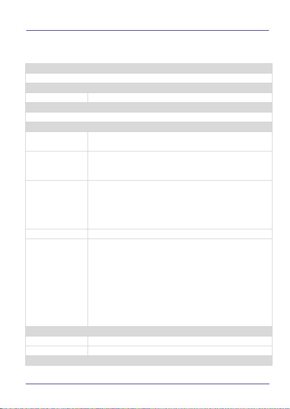
Products with power packs
Only the power packs supplied by Datalogic may be used. The power
pack may only be replaced by qualified personnel.
Internal power pack Power pack with handgrip
Rated Voltage 7.2 V 7.4 V
Power 18 Wh 19.24 Wh
Hazards during installation
Transport/installation
The product may fall during transport or installation and cause injury.
Seek assistance from a second person.
Hazard due to a device bracket defect
The product should be installed in such a way that no persons can be
injured if the bracket is faulty. If necessary, appropriate safety
measures must be taken, e.g. installing a safety rope.
Installation on vehicles
The field of vision and operability of vehicles must not be impaired by
the installed product.
Environmental conditions and IP protection
Environmental conditions allowed must be observed. In order to
achieve the IP protection class, the cables and the cable cover must
be installed as described in Cable Cover Installation on page 94.
6TaskBook
Page 13

Safety Instructions
Radio frequencies
Output power
The maximum allowed output power specified for the respective
country must not be exceeded. The operator of the product must
ensure this.
Distance between persons and antenna
A distance of at least 20 cm (7.87 in) is to be maintained.
Aircraft and hospitals
The product must not be installed in aircraft or hospitals without
permission.
Medical implants / pacemakers
The product may affect the functioning of medical implant devices
and cause interference. A distance of at least 20 cm must be
maintained.
CE marking
This device has been developed and manufactured according to VDE
and CE regulations.
User’s Manual 7
Page 14

Safety Instructions
Information for Scandinavian Countries
• NOR – Norway – Norwegen:
Apparatet må tilkoples jordet stikkontakt.
• SWE – Sweden – Schweden:
Apparaten skall anslutas till jordat uttag.
• FIN – Finland – Finnland
Laite on liitettävä suojamaadoituskoskettimilla varustettuun
pistorasiaan.
• DNK – Denmark – Dänemark
Apparatets stikprop skal tilsluttes en stikkontakt med jord,
som giver forbindelse til stikproppens jord.
• DEU - German - Deutschland:
Das Produkt muss an eine geerdete Spannungsversorgung
angeschlossen werden.
LED Warning
CAUTION! Possibly hazardous optical radiation emitted from this
product. Do not stare at operating lamp. May be harmful to the eyes.
8TaskBook
Page 15
Technical Data
Dimensions
The performance and autonomy of the device can be
affected by the power settings and the user environment.
NOTE
SH7 SH10
Length x slot width x height
Screen diagonal 17.89 cm / 7.04 in 25.75 cm / 10.13 in
15.0 x 18.7 x 3.8 cm /
5.9 x 7.3 x 1.5 in
Operating temperatures
TaskBook is designed to work in ambient temperatures between
-20° and 50° C (-4° and 122° F). TaskBook can be damaged and
battery life shortened if stored or operated outside of these
temperature ranges. Avoid exposing TaskBook to dramatic changes
in temperature or humidity. When you’re using TaskBook or
charging the battery, it is normal for TaskBook to get warm.
To maximize battery life at high temperatures, we suggest to lower
the brightness level and to enable power-save mode on the control
panel. High ambient temperatures might decrease performance
capacity.
27.9 x 18.7 x 3.8 cm /
10.9 x 7.3 x 1.5 in
User’s Manual 9
Page 16

Technical Data
Restrict the use of TaskBook if its surface is covered with ice or frost.
To ensure a reliable operation at low temperature, Datalogic
recommends to turn on the device and to carry out the bootstrap
when the device temperature is over 0°C.
To maximize the operating temperature range, Datalogic
recommends to keep the display brightness at maximum level only
for a short time.
10 TaskBook
Page 17
Wi-Fi specifications
Standard
IEEE802.11ac/a/b/g/n, Bluetooth V4.1,V4.0 LE, V3.0+HS, V2.1+EDR
Chipset
Mac/BB/RF Qualcomm Atheros QCA6174A-5
Host Interface
PCIe: WLAN, USB: Bluetooth
Radio
Antenna
Operating
Frequency
Modulation
Output Power (1TX) BT: (Class 2 Device) 0 ≤Output Power ≤+4dBm
Receive Sensitivity
Power consumption
Continue TX 405mA
Continue RX 200mA
Operating Voltage
2 x IPEX MHF4 connector, 2T2R
Support WLAN / BT co-existence
802.11 ac/a/b/g/n ISM Band
2.412GHz~2.484GHz, 5.150GHz~5.850GHz
*Subject to local regulations
802.11a: OFDM (BPSK, QPSK, 16-QAM, 64-QAM)
802.11b: DSSS (DBPK, DQPSK, CCK)
802.11g: OFDM (BPSK, QPSK, 16-QAM, 64-QAM)
802.11n: OFDM (BPSK, QPSK, 16-QAM, 64-QAM)
802.11ac: OFDM (BPSK, QPSK, 16-QAM, 64-QAM, 256-QAM)
802.11a: ≤-66dBm@54Mbps
802.11b: ≤-81dBm@11Mbps
802.11g: ≤-66dBm@54Mbps
802.11gn (HT20):-65dBm@MCS7
802.11gn (HT40):-61dBm@MCS7
802.11an (HT20):-65dBm@MCS7
802.11an (HT40):-61dBm @MCS7
802.11ac (VHT80): ≤-56dBm@MCS9
BT: < 0.1%BER at -70dBm
Technical Data
User’s Manual 11
Page 18

Technical Data
DC 3.3V ± 10% I/O supply voltage
Software
Driver Windows 7/8.1/10
Security 64/128-bits WEP, WPA, WPA2, 802.1x
12 TaskBook
Page 19
TaskBook Interfaces
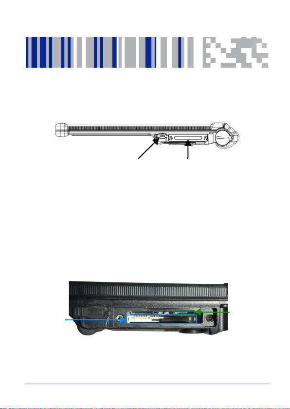
USB-C Connection
CFast Cap
CFast Slot
SDHC Slot
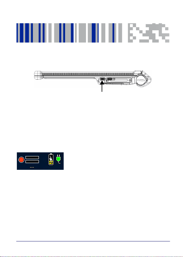
USB-C Connection
The TaskBook has a USB-C interface. This port can be used to charge
the TaskBook’s internal battery. The USB-C connection is found on
the lower surface of the TaskBook and is protected by a dust cover.
CFast Slot
Behind the CFast cap there is a CFast card (Windows 10). In order to
eliminate the CFast-cap, both Tx8 screws must be released.
The CFast card is held with a label, which helps it move away from
the slot.
A free slot for additional SD cards (SDHC or SDXC) is also available in
this area. Once an SD card is inserted, lightly press on the cart itself
User’s Manual 13
Page 20
TaskBook Interfaces
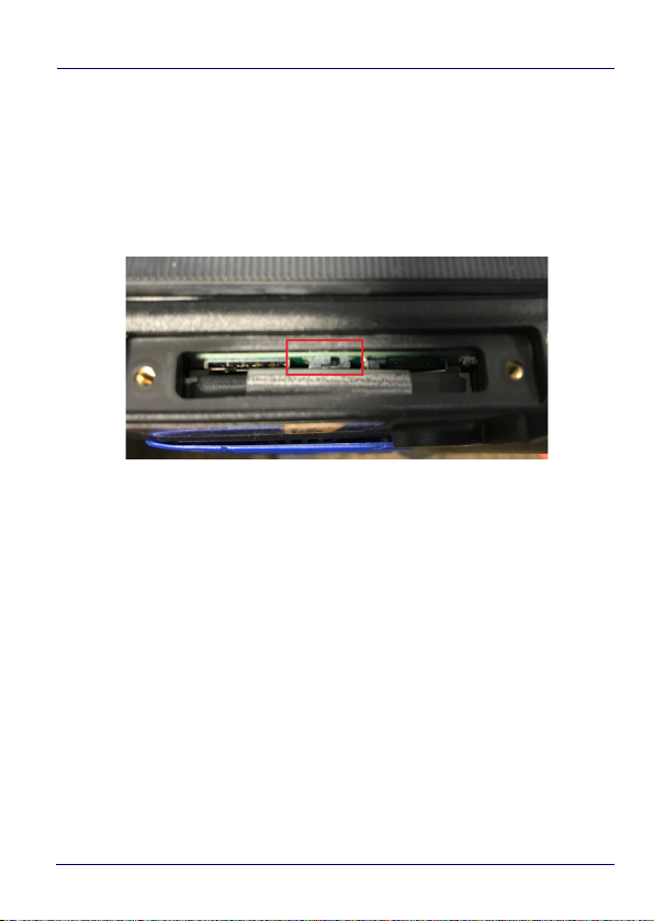
to release it. The SD cards are then released and can be slightly
pulled out of place from the slot.
Just above the CFast, a small black switch controls the power supply
chain to all the motherboards. Slide the switch to the left position to
disconnect the internal battery. Use this switch only when you want
to perform a hard hardware reset and avoid any further use. A wrong
setting of this switch will prevent the TaskBook from booting.
14 TaskBook
Page 21
Charging Internal Power Pack
USB-C Connection
USB-C Interface
In order to be able to charge the device using the USB-C connection,
the power supply has to support the USB-C Power Delivery (PD)
specifications of a minimum of 9 V (max. 20 V) and 3 A. The
accessory 94ACC0228 complies with these requirements.
The TaskBook can be charged via the USB-C
interface. As soon as the charger is
connected, a charging symbol appears in the
upper right corner of the screen. Additionally,
the charge LED on the buttons bar will light up red.
User’s Manual 15
Page 22
Charging Internal Power Pack
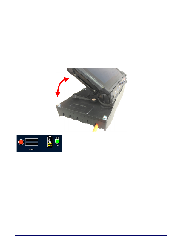
Docking station (AC or DC)
You can charge the TaskBook by inserting it in a Docking Station (PN
from 94ACC0214 to 94ACC0225) connected to the power line/ vehicle
battery. To insert the TaskBook in the Docking station, rest the
buttons bar side on the docking station and hinge it down with a
rolling movement.
As soon as the docking station is connected, a
charging symbol will appear in the upper right
corner of the screen. Additionally, the charge
LED on the sensor bar will light up red.
Handgrip
You can charge the TaskBook by using the detachable handgrip (PN
from 94ACC0211 to 94ACC0213) containing a charged battery. Rest
the buttons bar side on the handgrip and hinge it down with a rolling
movement until it clicks.
16 TaskBook
Page 23

Charging Internal Power Pack
An additional power pack symbol will
appear in the upper right corner of the
screen. When connected through the
handgrip, the internal power pack is
charged by the handgrip's external power
pack. In addition, “Charge” LED on the sensor bar will start to light
up red and the “EXT BAT” LED will light up green, provided the
external power pack has sufficient capacity. When the internal
battery is fully charged the “Charge-LED” is switched off while the
“INT BAT” and “EXT BAT” green leds are both light up.
The internal power pack is charged until it has reached
approximately the same level of power as the external power pack.
For full charging of the internal power pack, the use of either the
docking station or a compatible USB-C PD power supply is
recommended.
User’s Manual 17
Page 24

Charging Internal Power Pack
NOTES
18 TaskBook
Page 25
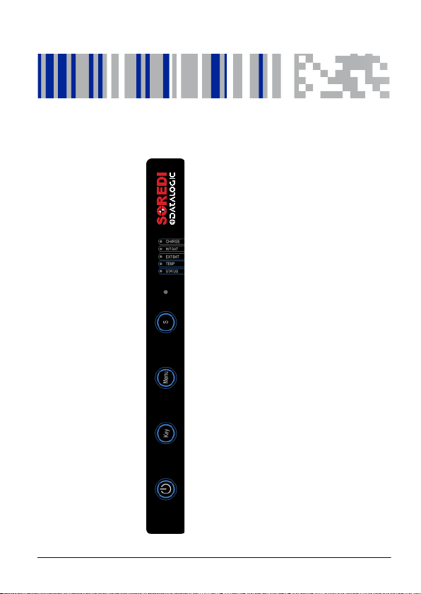
Status LEDs
Brightness Sensor
S Button
Menu Button
Key Button
Power Button
Buttons Bar
User’s Manual 19
Page 26

Buttons Bar
Status LEDs
The sensor bar has 5 status LEDs.
CHARGE - LED
Charge – LED lights up solid red when the internal battery is
charging. If it blinks, the internal battery is faulty and must be
checked.
INT BAT – LED
The INT BAT – LED provides information about the status of the
internal rod battery. If the charge level is between 100% and 30%, the
LED lights up solid green. If the capacity of the power pack falls below
30%, the LED blinks green.
EXT BAT – LED
The EXT BAT LED lights up solid green as soon as an external power
source is connected. External power sources include the docking
station, the USB-C charger and the handgrip power pack. The LED on
the handgrip battery pack starts blinking as soon as the battery
capacity drops below 30%. The INT BAT – LED and EXT BAT – LED don't
necessarily blink simultaneously.
TEMP – LED
If the temperature of the TaskBook falls below the minimum rated
specification or exceeds the maximum rated specification, the
TaskBook will automatically switch off to protect itself from damage.
In this case, the Temp – LED lights up red and will only stop when the
internal temperature has returned to normal. If the Temp – LED is lit
up, the TaskBook cannot be switched on.
STATUS – LED
The Status – LED indicates whether the device is switched on or not.
It also blinks green when the screen blanking is active. The screen
20 TaskBook
Page 27
Buttons Bar
blanking can be activated via a signal on the docking station's COM
interface.
Brightness Sensor
The brightness sensor adjusts the display brightness automatically.
This is disabled by default.
S Button
The S Button is a programmable button. It can be used as a shortcut
for frequently used keys/functions/programs.
For information on how to customize such button, see Device Basic
Configurations on page 37.
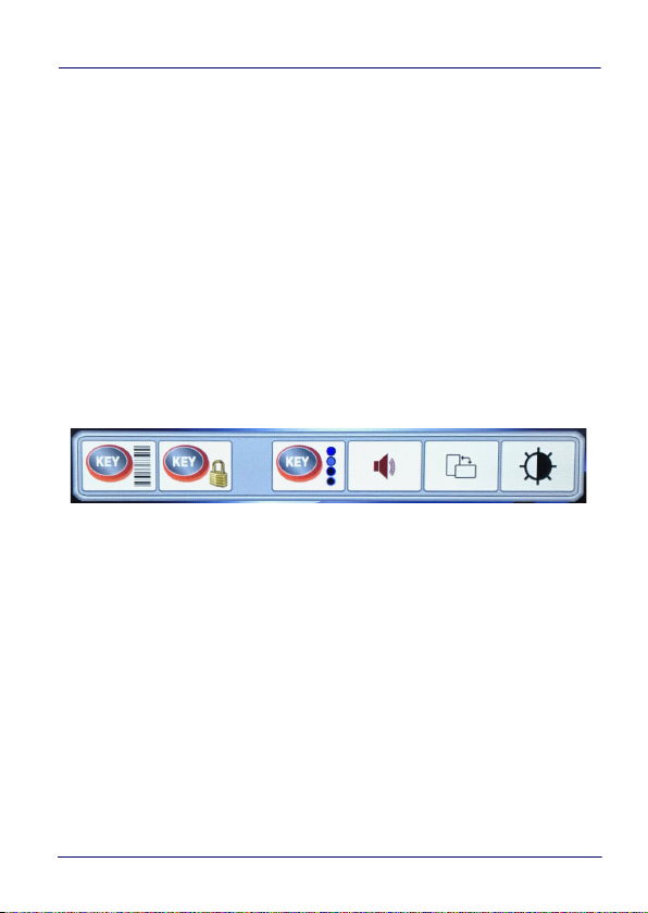
Menu Button
The Software menu is called up using the Menu button.
The following options are available:
• Activate scan function for the buttons bar
•Activate key lock
• Adjust the brightness of the buttons bar
• Change the volume
• Rotate the display orientation (portrait or landscape)
• Change the Brightness
User’s Manual 21
Page 28
Buttons Bar
Scan Function
This function allows to set the buttons in the buttons bar as soft
triggers to scan barcodes. After pressing the Scan Function key:
•the menu bar disappears
• the message "Scan function for key bar ON" appears for a few
seconds
• the icon appears on the screen.
When this function is activated the scanner can be triggered with the
following buttons:
•S
•Menu
•Key
The above listed buttons will only act as scan triggers while this
function is active (i.e. while the icon is on the screen).
To exit the Scan Function, press the Lock button on the screen. The
message "Scan with every button OFF" will appear for a few seconds
to confirm that this function has been disabled.
You can drag and drop the Lock icon to another position on
the screen if desired.
NOTE
22 TaskBook
Page 29
Buttons Bar
If you enable the Scan Function without the handgrip, the
system will enter Key Lock mode (see next section).
NOTE
Key Lock Mode
This function allows to lock the buttons on the buttons bar.
After pressing this button:
• the menu bar disappears,
• the message "Key Lock ON" appears for a few seconds
• the icon appears on the screen
When this function is activated, the following buttons are locked:
•S
•Menu
•Key
To exit the Key Lock Mode, press the lock button on the screen. The
message "Key Lock OFF" will appear for a few seconds to confirm
that this mode has been disabled.
You can drag and drop the Lock icon to another position on
the screen if desired.
NOTE
User’s Manual 23
Page 30

Buttons Bar
Buttons Bar Brightness
Press the above button to switch to a different light setting for the
button bar. The available settings are:
• Key Illumination ON Half Intensity
• Key Illumination ON Full Intensity
• Key Illumination OFF Half Intensity on pressing
• Key Illumination OFF Full Intensity on pressing
When a Key Illumination OFF profile is selected, the blue back light of
the buttons bar turns off; it turns on when you press the button.
Volume Control
Press this button to adjust the volume. Increase or decrease the
volume level by scrolling the slider.
24 TaskBook
Page 31

Buttons Bar
Orientation Portrait/Landscape
Press this button to switch from portrait to landscape mode and
vice versa.
Landscape Orientation
User’s Manual 25
Page 32

Buttons Bar
Portrait Orientation
26 TaskBook
Page 33

Buttons Bar
Brightness Control
Press this button to adjust the screen brightness. Increase or
decrease the brightness level by scrolling the slider.
User’s Manual 27
Page 34

Buttons Bar
Key Button
Touch the key button to call up or remove the SoftKey Keyboard.
The SoftKey Keyboard is totally customizable in terms of keys, colors,
button locations, etc. (see Software Keyboard on page 51). By default
it comes with 3 different configurations available: QWERTY,
NUMPAD, FUNCTION MODE.
Changes the keyboard layout to numpad mode.
Changes the keyboard layout to QWERTY mode.
Changes the keyboard layout to F1 - F12 - mode.
Toggles the 3 keyboard sizes (small, medium, large).
Tap and hold this symbol to position the keyboard freely on the screen.
Qwerty
28 TaskBook
Page 35

Buttons Bar
Numpad
Function Keys
Power Button
Press the power button for at least 5 seconds to suspend the
TaskBook. Hold the power button for at least 10 seconds for a hard
reset.
To switch on the device, either the INT BAT – LED or the EXT BAT –
LED must be lit up green.
The pressure time needed to trigger the power on or off is
customizable. See Frontkeys on page 42 or StartUp/ShutDown
Mode on page 45 for more details.
User’s Manual 29
Page 36

Buttons Bar
NOTES
30 TaskBook
Page 37

Wi-Fi Settings
The TaskBook has a SparkLAN WNFQ-258ACN(BT) Wi-Fi card with
Qualcomm Atheros QCA6174A-5 chipset. The necessary drivers are
pre-installed. The Wi-Fi settings are configured via the Windows'
own Wi-Fi settings.
User’s Manual 31
Page 38

Wi-Fi Settings
NOTES
32 TaskBook
Page 39

Change Regional Settings
Change operating system language
Push the icon with the flag and wait for the following pop up to
appear:
Select the language you want to change to and push the OK Button.
The device then restarts and changes the language to the selected
language.
User’s Manual 33
Page 40

Change Regional Settings
Change Keyboard in Operating System
Open the Control Panel and select Change Keyboard Language. The
language you want to have has to be moved to the top with the Move
up button. Now the Windows-Keyboard is in the selected language.
34 TaskBook
Page 41

Change Regional Settings
Change Keyboard language
Go to the specified path C:Utilities >SoftKeys:
Delete all keyboard languages that are not needed, but save them
on a USB stick or similar if you need them again later.
Rename the file to the language which is set in the operating
system. Here the user wants to have an English-speaking device
with an Italian keyboard and therefore we renamed Softkey_IT.cfg
into Softkey_EN-US.cfg.
User’s Manual 35
Page 42

Change Regional Settings
NOTES
36 TaskBook
Page 43

Device Basic Configurations
Advanced settings for both Hardware and Software features are
configurable through the UtilConfig tool. All settings are saved in the
"\Utilities\UtilConfig.cfg" file and can be manually edited row by
row.
Some high-level options are also available through a graphical
interface.
UtilConfig Editor
There is a shortcut located on the desktop. Alternatively, UtilConfig
can also be opened via Start > Utilities > UtilConfig.
General section
The language of the UtilConfig can be set here.
User’s Manual 37
Page 44
Device Basic Configurations
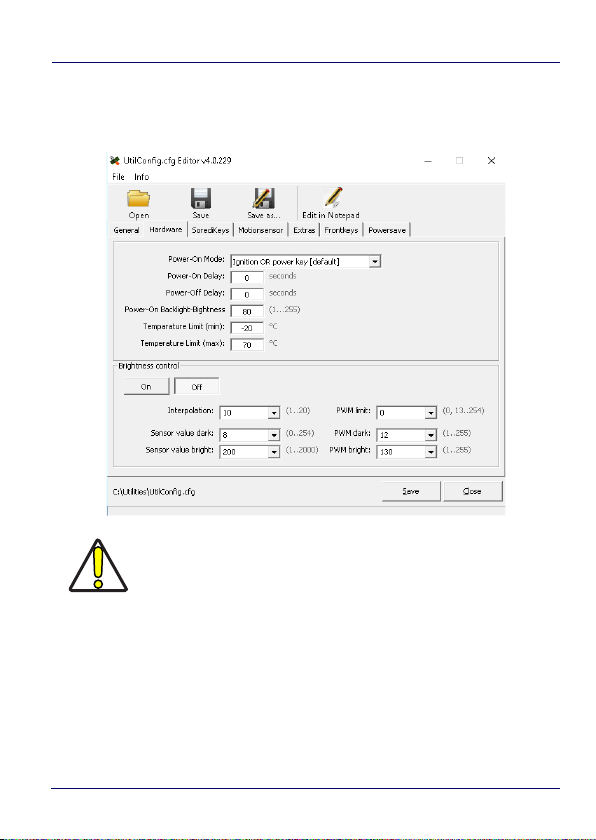
Hardware
The turn-on mode, the temperature limits and the brightness sensor
can be configured here.
The temperature must not exceed 70°C.
CAUTION
38 TaskBook
Page 45

Device Basic Configurations
SoredyKeys
Allows to define whether or not to enable the software keyboard.
User’s Manual 39
Page 46

Device Basic Configurations
MotionSensor
The availability of the Motion Sensor depends on the
model.
NOTE
40 TaskBook
Page 47

Device Basic Configurations
Extras
Allows to restart or stop the hardware service and the SoftKey ones.
User’s Manual 41
Page 48

Device Basic Configurations
Frontkeys
With this menu you can configure the commands of the keys on the
touch bar on the side.
You can use the Powerkey delay box on the top left corner to set the
pressure time required to turn on or off the device.
To prevent accidental power on/off, we recommend to set a
time between 3 and 5 seconds.
NOTE
42 TaskBook
Page 49
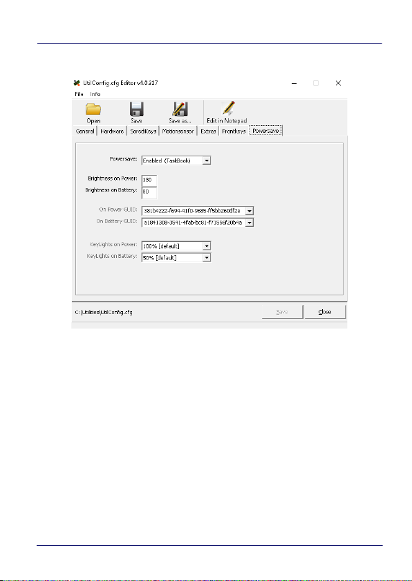
PowerSave
Device Basic Configurations
User’s Manual 43
Page 50

Device Basic Configurations
NOTES
44 TaskBook
Page 51

Advanced Device Configuration
StartUp/ShutDown Mode
The mode described below applies only to the TaskBook
inserted in the Docking Station with VDC power supply,
NOTE
The TaskBook has 3 modes of controlling Startup and Shutdown.
The mode is set by commands in the "\Utilities\UtilConfig.cfg" file.
Each mode controls how the Ignition Sense power connector wire
(IGN) and the TaskBook’s front panel Power button (PWR) work
together. In the default mode (mode 1), IGN must be at a voltage
greater than 10 VDC and PWR must be pressed and held for a
specified period to power up the VMC. Shutting down in this mode
may be accomplished by removing the positive voltage from IGN or
pressing the PWR button, either must be for a specified time to
shutdown.
The other common mode (mode 0) allows IGN or PWR to control the
Startup/Shutdown. In this mode connecting IGN to positive voltage
will power up the VMC, and disconnecting it will power down.
Similarly powering up via PWR then pressing PWR again will power
back down. If using PWR to control the VMC in this mode, IGN
should NOT be switched or tied to + power. When using this mode
you should either be exclusively using IGN to control the VMC, or
PWR but not mixing the two.
the use designed for VMC solutions.
User’s Manual 45
Page 52

Advanced Device Configuration
If the VMC is powered up via IGN, but powered down via
PWR, it will immediately begin to power back up.
NOTE
The final mode (mode 3) is seldom used. In this mode, the VMC will
power up anytime there is power applied. Both IGN and PWR are
ignored in this state.
When the VMC is being powered down by IGN, it will typically display
a countdown screen advising the user the remaining time before the
terminal shuts down. The shutdown time as well as whether the
countdown is displayed are both controlled by the configuration file.
Configuration (in \Utilities\UtilConfig.cfg):
• PowerOnMode sets the Startup/Shutdown mode.
- 0 = IGN or PWR
-1 = IGN and PWR
-3 = AutoOn
• IgnOffDialog displays the shutdown timer window when IGN is
turned off
- 0 = Do not display the window
- 1 = Display the shutdown timer window
• IgnOffDlgType size of the shutdown timer window if enabled
- 0 = Full screen display, no user interaction is allowed (not
recommended)
- 1 = Medium size display, user may move the window and
interact with the system
46 TaskBook
Page 53

Advanced Device Configuration
- 2 = Small size display, user may move the window and
interact with the system
• IgnStartTimeSec seconds after IGN goes high before the VMC
begins booting
• IgnOffDelayTimeSec seconds after IGN disconnects before the
VMC shuts down
• DelayPowerKey milliseconds PWR must be pressed before
the VMC begins booting.
User’s Manual 47
Page 54

Advanced Device Configuration
Front Panel Keys
There are three programmable buttons on the buttons bar. The
programming is set by command lines in the
"\Utilities\Utilconfig.cfg" file as well as with the GUI described in
UtilConfig Editor on page 37. The configurable buttons have the
following functions:
• PWR – Starts & shutdowns the terminal depending on the
current Startup/Shutdown mode.
• 1 – Up arrow.
• KEY – Display/remove the soft keyboard from the screen.
Normally the PWR and KEY buttons should not be reprogrammed,
but they are available if required.
Configuration
The listed values are the default values from the factory. Setting
PWR and KEY to blank causes them to execute Startup/Shutdown
and Softkeyboard respectively. The VK values for each key are listed
in the SoftKeyboard section of this document. Multiple values can be
entered for a key by using comma to separate the values. For
example, the definition Frontkey_S1=#EXT=VK_TAB,VK_RETURN
would cause the S1 key to transmit tab, then a return key.
•Frontkey_PWR=
• Frontkey_S1=#EXT=VK_UP
• Frontkey_S2=
• Frontkey_S3=
• Frontkey_S4=
•Frontkey_KEY=
48 TaskBook
Page 55

Advanced Device Configuration
The TaskBook also provides the ability to lock the individual front
panel keys. There are two keywords to control the state of the keys
when the function mode is off (HWKeyLockFNOff) and when the
function mode is on (HWKeyLockFNOn). Each of the keywords is an
8 bit mask, using one bit each to control the individual keys. Bits 0-7
are:
•PWR (1)
•BL (2)
•+ (8)
• - (16)
• S1 (32)
• S2 (64)
• FN (128)
• KEY (256)
Setting the specific bit to a 1 will lock the respective key. For
example, setting HWKeyLockFNOff=66 would disable the BL (2) and
S2 (64) buttons when the function mode is not set. Setting
HWKeyLockFNOn=256 would disable the KEY (256) button when the
function mode is set.
Be aware that if you are attempting to control the PWR
button, you can lock the TaskBook. Disabling the PWR
button at the same time you have the startup mode set to
NOTE
IGN and PWR will block the TaskBook from being able to
be powered up.
User’s Manual 49
Page 56

Advanced Device Configuration
Screen Blanking
This applies only when TaskBook is used on a docking
station installed on a forklift and the screen blanking cable
NOTE
The TaskBook has the ability to blank the screen when positive
voltage is applied to a designated COM port pin. This is typically used
to blank the screen when a vehicle is in motion, a requirement is
some countries. For the TaskBook, an external sensor must be used
that will either provide a positive voltage when the vehicle moves, or
closes a relay in the same circumstance. If using a relay, then the
positive voltage from pin 9 of the selected COM port should be wired
as input to the relay. The output from the sensor or relay should be
wired to pin 1 (DCD) or pin 6 (DSR) of the selected COM port. The
screen blanking cable from Datalogic (p/n 94ACC0157) is wired to pin
9 (pink) and pin 6 (grey).
Configuration
Locate (or add) the line ScreenBlankBits=X in the [General] section of
the file. X should be set to the appropriate value from the list:
• 1 – COM1: DCD (pin 1)
•2 – COM1: DSR (pin 6)
• 4 – COM2: DCD (pin 1)
•8 – COM2: DSR (pin 6)
Deleting the ScreenBlankBits line from the cfg file will turn off screen
blanking.
is connected to the motion sensor of the vehicle.
50 TaskBook
Page 57

Software Keyboard
Keyboard Configuration File
The Configuration file is a text file built in sections to provide the
definitions for the keyboard layouts. Comments can be marked at
beginning of a line with a semicolon (;).
Section [Common]
In this section general settings will be defined.
Certain settings can be overridden explicitly within the definition
sections of the actual keyboard data for the respective keyboard.
These settings are explained separately in a 2nd table.
General Settings
Keyname Parameter – Info
Directory name for all used Bitmaps within this Cfg. The
ImagePath
KBShowOnStart=X
specified directory is always searched in the list of the
specified CFG file. A complete path specification is
supported.
With this parameter a fixed specified Keyboard will be
shown automatically after the start. X stands for the
Keyboard-Number from the Keyboard-Config. For example,
KBShowOnStart=1 always shows the Keyboard from the
Cfg-Section [Keyboard_01].
If no keyboard should be visible at the start, X can be set to a
invalid Number, e.g. 100 or the parameter can be left out.
not
User’s Manual 51
Page 58

Software Keyboard
Keyname Parameter – Info
SysAdminPwdKB
SysAdminMenKB
RotateScreen
Specifies the defined keyboard number for a password
keyboard.
Specifies the defined keyboard number for a
SysAdmin-Menu-Keyboard.
With this you can specify the angle of rotation which is set
by the key function VKX_KB_SCRROTATE. A maximum of
four values are possible (0=Default-Systemstartup, 1=90°,
2=180°, 3=270°). For rotation minimum 2 values must be
defined. For example RotateScreen=0,1 is defined, it will be
toggled between these two angles. If the Key isn’t existing
or empty, all 4 values will be set one after another.
Pre-settings for Keyboards
These settings apply here for all following keyboard definitions,
however, they can be explicitly overridden in the keyboard definition
for special cases.
Keyname Parameter – Info
FrameImage
TitleBar
Title
AlphaValue
BitmapName.bmp,FrameSizeX,FrameSizeY
Bitmap for the Keyboard-Frame and to set the background.
FrameSizeX
FrameSizeY
A keyboard without frame can be defined.
0 (=Default)
With 1 the Windows title bar can here be activated for special
cases.
Here, any string can be defined as titles for TitleBar,
e.g. “Soft Keyboard“.
0 (=Default – no Transparency)
Here values of 10 (almost completely transparent / invisible)
to 250 (almost opaque) are accepted.
defines the left and right distance to the keys.
defines the upper and lower distance to the keys.
52 TaskBook
Page 59

Keyname Parameter – Info
0 (=Default – not transparent respectively invisible colour)
Here, a colour can be set that is completely invisible in the
output, i.e. the background is completely visible. This will, for
TransparentCol
example, be used to produce Window frames round corners or
to paint the icons used regardless of the background colour of
the buttons.
Usually, purple is mostly used. The colours are always in RGB
notation, Example: “TransparentCol=255,0,255“
Here a maximum 10 zoom values are specified, separated by
commas. The values are always specified as a percentage (e.g
200 = twice as large as normal).
ZoomFactor
The starting size of a keyboard is always 100% in accordance
with the key sizes specified in the keyboard definition, etc. The
value 100 must not be specified separately in the Zoom list - it
is automatically inserted at the beginning.
0=Off, 1=On (Default), on default the Repeat function is
RepeatKeys
activated. For special Keyboards with special functions this
Repeat function is mostly not desired.
0=Off (Default), 1=On, allows freely moving Keyboards with
finger. Therefore you must press anywhere on the Keyboard
AutoMove
and immediately start to move (wipe) it around. If this function
is activated, which results in a slight delay (~ 100 ms) when
releasing (or pressing) the key. If you tap the key only briefly,
the key function is executed without further delay on release.
0=Off, 1=On (Default), the Snap function – means the snapping
on the screen corners and if there is enough space also centred
on the edges – only works in conjunction with the option
AutoMove=1. To trigger the automatic snapping, with a short
AutoSnap
wipe the keyboard must be moved to the right direction. Only
at short wiping movements (< 500 ms) the Snap function is
activated If the movement of the keyboard takes longer, you
can move it to any position (without snapping). The screen
sizes are not supported for snapping.
Software Keyboard
User’s Manual 53
Page 60
Software Keyboard
Section [VolumeTouchCtrl]
This section defines the graphics used in the touch screen volume
control.
Background The bitmap displayed as the background of the volume control.
Pointer Bitmap used to indicate the current volume.
MuteIcon When the speaker is muted, this bitmap will be displayed.
Section [Fonts]
In this section all fonts used with the keyboard (max. 40) will be
defined.
Keyname Parameter
Fontname
The various fields can be assigned as follows:
Fontname
Font name
Width
Height
Text- R,G,B
Shadow - R,G,B
Shadow offset X,Y
Format
font name, width, height, Text (3 cols),Shadow (3 cols), shadow
offset (2 cols), format
For this keyname any name can be given, according to the use
of fonts. If the font definition will be used later for the keys,
the font must be specified in this section.
Name of the desired and installed Windows system font.
Width
0 will be used as default, so the font is displayed in its
natural width. For special cases the character width will be
stretched or compressed.
The height of the font in pixels.
In these 3 fields, the red, green, blue values for the font
colours are defined.
For all RGB fields values from 0-255 allowed.
In this 3 fields the R,G,B values for shadow colours are defined.
Shadow offset in pixels. Setting offset to 0 = no shadow.
If specified, font formatting may be set to italic (I) and/or bold
(B).
54 TaskBook
Page 61

Software Keyboard
Example:
FontDef = Arial, 0,26,0,0,0,190,190,190, 2,2,B
FontMini = Tahoma, 0,14,0,0,0,190,190,190, 0,0,IB
FontSymbol = Wingdings, 0,29,0,0,0,190,190,190, 0,0,B
Section [Keys]
In this section the general and for all keyboards valid definition for
the layouts of the single keys will be specified.
Max. 40 individual Key-Layouts can be created.
Keyname Parameter
KeyName
The various fields can be assigned as follows:
KeyName
FontName
BMPNormal
BMPActive
TxtMode
IconMode
FrmXL, FrmYL
FontName,BMPNormal,BMPActive,TxtMode,IconMode,FrmXL,FrmYL,
FrmTxtNormL,T,R,B, FrmTxtActL,T,R,B, FrmIconNormL,T,R,B,
FrmIconActL,T,R,B
This KeyName can arbitrarily be named. If the key will be
used later on the keyboard, the corresponding defined
KeyName
must be specified.
The Fontname from the [Fonts] section to be used.
Bitmap for normal key display (not pressed).
Bitmap for active key display (pressed).
Here the orientation for the text output can be
determined, per default the text will be displayed always
horizontal and vertical centered in the key.
L=left-aligned, R=right-aligned, T=top, B=bottom.
Combinations like e.g. "LT" or "LB" are allowed.
Orientation for Icon-Positioning, identical to
Here special frame values for the allocation of Bitmaps
(
BMPNormal + Active
smaller Buttons. Normally it isn’t necessary and the
values should be left empty.
) can be set to create bigger or
TxtMode
.
User’s Manual 55
Page 62

Software Keyboard
Position frame for the text output in normal keys.
With the values L=Left,T=Top,R=Right,B=Bottom
FrmTxtNormL,T,R,B
FrmTxtActL,T,R,B
FrmIconNormL,T,R,B
FrmIconActL,T,R,B
substituting the distances of the text output to the side
edge. This is necessary so that the text will not be written
over the 3D-Frame of a key by left-aligned output.
Position frame for the text output at active/pressed keys.
The frame for the active Display will be specified in 1-3
Pixel (depends on key size). In this case the effect of a
pressed key will appear.
Position frame for the Icon output of normal keys.
Position frame for the Icon output of active/pressed keys.
Section [Keyboard_XX]
This section provides the actual definition of the keyboards. Max. 20
Keyboards (XX = 01-20) are possible for each Cfg-File. A Keyboard
Definition is only recognized as valid if at least the line "L01_Norm" is
defined in the section (see description below).
With horizontal screen orientation (Landscape), the default
definitions are read, for example, [Keyboard_01].
In vertical orientation (Portrait-Mode), first the system tries to read
the keyboard definition from the
Section [Keyboard_XX_Portrait], for example from
[Keyboard_01_Portrait]
If nothing is defined in the Portrait-Section (at least L01_Norm) or
the section doesn’t exist, the default landscape will be used.
56 TaskBook
Page 63

General Settings
Keyname Parameter - Info
Name
DefaultKeyName
DefaultKeySize
Position
CloseOnClick
CloseToggle
CloseOnTimer
Individual Name for the Keyboard. This name can be shown
optional in the Title bar (or can be eventually be used later to
control the keyboards).
Here the KeyName layout from the [Keys] section will be
specified, which will be used for all keys.
XLength,YLength
Standard-Key size for this Keyboard in Pixels.
XPos,YPos
Start position of the keyboard in pixels. Should the keyboard be
moved by the user, this new position is stored in the registry
for each keyboard and used in subsequent starts.
0=Off (Default), 1=On, this mode automatically closes the
keyboard after pressing or executing a button
0=Off (Default), 1=On, an open keyboard with this mode, by a
repeated call (e.g. carry out by a key or a HW-Key) can be
closed again.
0=Off, Value >= 1000 specifies a timeout value in milliseconds
for this keyboard. If the timer runs out, the keyboard will be
automatically closed. A keystroke on the keyboard will start
the timer each time again
Software Keyboard
User’s Manual 57
Page 64

Software Keyboard
Definition of Keyboard-Layouts
The definition of the keyboard layout is done in single lines. For each
line 3-Cfg Keys are possible, according to the status of the special
keys. Max. 20 key lines can be defined per keyboard.
The overall size of the keyboard is automatically calculated based on
the contained buttons.
Keyname Parameter - Info
LXX_Norm
LXX_Shift
LXX_AltGr
Definition of the Key row XX for the normal key status.
Definition of the Key row XX for the status at pressed Shift-Key.
Definition of the Key row XX for the status at pressed AltGr-Key.
For XX any number from 01-20 can be specified.
The Syntax is always the same, e.g.:
LXX_Norm=Key1¦Key2¦Key3¦...¦
It is important that even the last keymust always must be
terminated with the vertical bar character "¦".
The number of keys within a row is not explicity limited, but no more
than 300 keys per keyboard can be defined. Overlapping keys will not
be checked, the definition must be correct at any time.
Syntax of a Key Definition
The syntax of a key is constructed as: "#Command;VK_CODE;Text¦"
Single Fields and Commands will be separated through a Semicolon
(;).
Each Key must be finished with the vertical bar character ("¦"
Ascii-Code=124).
Special Commands will be introduced with the Character "
Should one of these reserved characters be indicated in the text or as
a key code, the Hex-Code must be used:
• "|" = "0x7C"
#".
58 TaskBook
Page 65

Software Keyboard
• "#" = "0x23"
• ";" = "0x3B"
The fields "
#Command" and "Text" are optional, so that a minimum
definition can look like: "A|".
The generated Key code as well as the label of the key is defined
with "A". This works with single characters only. For other special
keys, special "Virtual Keycodes (VK)" are defined. (See table below).
If in a text for a key the combination "0x0A" is used, it will enforce a
word-wrap in the label of this key.
Example: "Row 1 0x0A Row 2".
However the possibility of vertical centering will be lost if using
word-wrap.
Commands for Key Definitions
Important: Position fixes and changes are evaluated only in the
"LXX_Norm" line. The Shift and AltGr-definition position changes are
ignored, as it could otherwise lead to conflicting data.
Set Bitmap-Icon for this Key. This icon can also be used for
#ICON=<file>
#KDEF=<key>
#KUSE=<key>
#KUSE2=<key>
different colour designed keyboards, it should be drawn on
transparent background.
If <file> has no file ending automatically „.bmp“ is appended.
Enables a new Key-layout <key> (from Section [Key]) for this
and all subsequent keys of that row. For new lines, the layout
is always automatically reset to the DefaultKeyName.
Sets the key layout <key> (from Section [Key]) explicitly for the
current key.
Sets a 2nd Key-Layout for a 2nd Text.
User’s Manual 59
Page 66

Software Keyboard
Change the length of the actual Key to <Size>.
<Size> is evaluated as a floating point number and returns the
#KXL=<Size>
#KYL=<Size>
#YADD=<Size>
#SP=<Size>
#EXT=<name>
#VXT=<name>
#EXEC=<exedef>
size relative to DefaultKeySize Example: “1“ corresponds
exactly to DefaultKeySize, “1.5“ 150% of the size and “2“ 200% of
the default size.
Change the height of the actual key to <Size>.
Change the general Y-Position for the key positioning. When
setting the first key, for example all following lines/keys can be
deducted from the upper keys.
Adds an appropriate distance before the current key.
Allows the definition of several key codes with one key.
For a detailed description see the following section.
Allows the direct definition of key codes for one key. The
format is identical to #EXT certainly with #VXT the data’s can
directly be written into the Key definition, the bypass over a
Key in the [ExtendedKeys]-Section is here not necessary.
Executing of Windows-Shell-Commands. In <exedef> defined
Name must indicate a definition from the Section [Execute]. In
the Execute section all commands must be defined and
grouped together to perform.
#KUSE2 for Creative Inscriptions
With #KUSE2 a complete 2nd Layout for a key from the section [Keys]
can be set. #KUSE2 must be always at the end of the Keydefinition.
The first Keytext should be explicit defined with "Text".
The fields BMPNormal,BMPActive of the KUSE2-Layouts will always
be ignored.
#KUSE2 always applies only to the definition of a current key.
Example:
L05_Norm = ...|VK_F1;"F1";#KUSE2=<Layout2>;"This is the KUSE2
Text :-)"|...
60 TaskBook
Page 67

Software Keyboard
L05_Norm = ...|VK_F1;"F1";#KUSE2=<Layout2>;"This is 0x0A two
lines added"|...
Keycodes Definition with #EXT
If you want to assign a key with multiple codes, this is done by
means of #EXT definition within a key definition. Using #EXT only
the symbolic name of the definition is indicated. The actual
definition of each key code will be executed in the section [Extended
Keys]:
DefName1=Key1,Key2,Key3,.....
DefName2=Key1,Key2,Key3,.....
In the section a maximum of 20 different strings can be defined with
multiple key codes. The maximum length of the symbolic name
DefName is 50 characters. In a definition (in a row) a maximum of
100 key codes may be defined. As a separator between different
codes a comma is used. To generate a comma, this can be done
through the name VK_COMMA.
To assign a keyboard key with Ctrl-Alt-Delete, the following
definition must be specified:
DefName=#CTRL_ALT_DEL
Before releasing a Key sequence, all other Keys will be "released" to
prevent problems with mixing of keystates like Shift, Control and Alt.
Example:
[ExtendedKeys]
MyTestString = This is a test!
TextExt1 = @
TestExt2 = VK_ALTGR,q
Special = VK_ESCAPE,VK_F1, This was ESC and F1
[Keyboard_XX]
User’s Manual 61
Page 68

Software Keyboard
L01_Norm =
^|#EXT=MyTestString;1|2|3|4|5|6|7|8|9
L01_AltGr = | |#EXT=Special;²|³| | | |{|[|]|}|\|
Like in the above example TestExt+2 shown, Keys can be
generated through different definitions.
If you have problems with specific combinations try explicitly the
respective left and right code definitions of Special Keys, e.g.
VK_LCONTROL, VK_RSHIFT, etc. ...
Status keys as VK_SHIFT, VK_CONTROL, etc. ... always affect only the
directly following 'real' key. For example should F5 are pressed with
Shift and F6 with Shift + Control, it must be specified as follows:
Special = VK_SHIFT,VK_F5,VK_SHIFT,VK_CONTROL,VK_F6
Section [Execute]
In this Section programs for availability with Soft Keys can be
defined. Using a key definition with EXEC# = <ExecDefineName>,
the key can launch the defined program.
Execute Assignments are only allowed for normal user keyboards. In
Soft-Keyboards, for example appears in UAC-, System- or
Login-Screens, the execution of any Program is permitted. To prevent
a possible mixing or problems with the KB-definition, the following
settings allow defining a separate logon keyboard.
The Section Keyboard also includes other general settings and is
described in SorediService documentary.
File: SoftConfig.cfg
Section: [Keyboard]
Settings: LogonKeyboardCfg=<...Path...LogonKeyboardConfig.cfg>
62 TaskBook
Page 69

Software Keyboard
The format of the definitions in the Execute section looks like this:
ExecName = ProgramName,Callparameter,Directory
Example:
[Execute]
InternetAddress=“www.google.de“
ElevatedApp=^calc.exe
Network=control,netconnections
CtrlPanel=control
AdminTaskMan=runas.exe,/user:administrator taskmgr.exe
User’s Manual 63
Page 70

Software Keyboard
System-Admin and Password-Keyboard
The system admin menu or keyboard is always linked with the
upstream password entry.
The behaviour is defined as follows:
• If the SysAdmin-Menu is not active at pressing the
KEY-Button, always the entry password dialog appear.
• If the SysAdmin-Menu is active at pressing the KEY-Button
the normal Keyboards like usually will be fade in or fade out.
•If the SysAdmin-Menu will be exit, all normal open Keyboards
will be closed automatically.
Both keyboards in the [Common] section of the Keyboard Config can
be activated as follows:
SysAdminPwdKB=Num
SysAdminMenKB=Num
For Num the Number of the corresponding Keyboard-configuration
will be specified.
These Special-Keyboards, always should be specified after the
normal Keyboards.
If the Password-Keyboard for example is defined in the Section
[Keyboard_10] the above entry would look like: SysAdminPwdKB=10
Attention:
SysAdmin....KB session allows to define the keyboards that will be
loaded by the microcontroller at the boot. When the SysAdmin...KB
sessions are specified, the Login-Session will not be considered.
64 TaskBook
Page 71

Software Keyboard
Password Keyboard
The Password-Keyboard can be configured
like any other Keyboard.
A complete Keyboard (incl. Letters) can be
configured below the entry field.
The Password-Keyboard appears after
pressing onto the KEY-Button, if the
SysAdmin-Menu is not open. Another
push on the KEY-Button deletes the
password keyboard from the screen.
When configuring the password keyboards
2 Key codes are of particular importance:
VK_ESCAPE = Escape (deletes the KB from Screen)
VK_RETURN = input (entry) ready
After receiving VK_RETURN the Password will be proved.
If the password is wrong an error message appears.
If the password is correct, the SysAdmin-Keyboard will open.
Special Settings Password Keyboard
Special Keys for configuration of password keyboards in the
[Keyboard_XX] Section:
Key Default Info
KeyDialog=DlgInputLine -
KeyDlgPassword=X -
To enable the Password entry, this key is
mandatory with the assigned registry.
For X any password can be defined. It is
only important, that all characters of the
password must be defined and shown in
the Password-Keyboard.
User’s Manual 65
Page 72

Software Keyboard
Key Default Info
KeyDlgText=Text
Password
For Text any text can be entered, which will
Input
prompt the PID input via the input line.
Here a Font definition from the Section
KeyDlgFont=FontDef -
[Fonts] can be given. The Text from
KeyDlgText is then output with this font.
Here the Colour value of a typical
Keyboard-Background-Colour should be
KeyDlgColor=R,G,B -
specified. In this case the displayed
Pwd-Dialog will be output in the same
colour. For the silver-grey Soft-Keyboard it
is for e.g.: 198,198,198.
For ErrText any Error-Message can be
defined. This will be shown after a wrong
KeyDlgPwdErr=ErrText
Invalid
Password!
Pwd-Input in the MsgBox. A line break can
be specified with '\ n'.
For X any number can be specified. This
gives a fixed waiting time in minutes. If a
KeyDlgPwdBlock=X 5
wrong password is entered 3 times the
Password-Dialog cannot be called up for
the duration of the specified waiting period.
If a 0 is specified, it will not be blocked.
With 1 this Keyboard will not be considered
ExcludeChain=1 0
at fading in/out of the normal
Input-Keyboards.
With 1 this keyboard is prevented from
StartupHide=1 0
displaying at startup - regardless of the
previous state.
66 TaskBook
Page 73

Software Keyboard
SysAdmin-Menu Keyboard
The Admin Menu Keyboard
displays after successful
password entry through the
above password keyboard. For
proper function this menu
keyboard is configured according
to the following section.
This Menu-Keyboard contains
always a special Key to Exit. This
Key must be defined with the
Keycode VKX_KB_HIDE.
Example: |#KXL=1.5;VKX_KB_HIDE;#ICON=Cancel;"Cancel"|
During this Menu-Keyboard is open, over the KEY-Buttons of the
unit all other Keyboards can fade in/out normally.
If the Menu-Keyboard will be Exit, all other „normal“ open Keyboards
will exit as well and after pressing the KEY-Button the
Password-Menu appears again.
Special Settings SysAdmin-Menu Keyboard
Special Keys to configure System-Admin Keyboards in the
[Keyboard_XX] Section:
Key Default Info
ExcludeChain=1 0
StartupHide=1 0
NormalWin=1 0
With 1 this Keyboard will not be considered at
fading in/out of normal Input-Keyboards.
When 1 this Keyboard will be prevented from being
shown at start – independent from the previous
Status.
With 1 the Admin-Menu will be set in a way, that it
looks like a normal Window and for example at
Start/Click on a different Application moves to the
background.
User’s Manual 67
Page 74

Software Keyboard
Key Default Info
PushForeground=0 1
When 1 the Admin-Menu is pevented from
automatically moving back in the foreground again.
Because the Admin-Menu might be behind other
ShowInTaskbar=1 0
Apps, it should be visible in the Taskbar (if shown)
to activate it again.
Title=<Keybd.Title> -
Name of keyboards which will be shown in the
Taskbar.
With this setting (ElevateAdmin=1) the
Admin-Menu-Keyboard can be started in the
ElevateAdmin=X 0
Elevated-Mode. In this case all other Keyboards
opened with KEY-Buttons are in the elevated
Mode.
Otherwise, the keyboard can be configured as a normal keyboard
with any buttons. This keyboard has the opportunity to create Keys
with executable programs or batch jobs.
68 TaskBook
Page 75

Software Keyboard
Virtual Keycodes
Special Function Codes
The following Function codes can be used to define Keys for special
functions.
VKX_KB_MOVEBUT Moving function for the Keyboard.
VKX_KB_ZOOM
VKX_KB_SWITCHTO=<kbdnum> Switches the keyboard to <kbdnum>.
VKX_KB_HIDE Deletes the actual keyboard from the screen.
VKX_KB_KBOPEN=<kbdnum>
VKX_KB_SCRROTATE
VKX_KB_UPDO
VKX_KB_KEYLIGHT
VKX_KB_VOLUMEDLG Open the dialog to set the volume.
VKX_KB_HWKEYLOCK
VKX_KB_HWKEYSCAN
VKX_KB_HWKEY_NORM Release the HW-Toolbar for normal use.
Zoom function for the keyboard. By pressing
this key, the next Zoom level will be activated.
Open the dedicated keyboard. The actual
keyboard remains unchanged displayed
(unless it isn’t defined with the Mode
CloseOnClick).
Rotates the screen orientation by 90°. The
orientation actually will not be stored. After
restart the unit will display again the default
orientation.
Change the Keyboard-Position from the upper
edge downward and vice versa. The vertical
X-Position will not change.
After pressing on this Button the lighting mode
of the HW-Keys will be switched between the 4
possibilities.
Blocks the HW-Toolbar completely (default).
This changing will not stored.
Turns the whole HW-Toolbar for scanning on.
This changing will not stored.
User’s Manual 69
Page 76

Software Keyboard
General Keyboard Codes
VK_SEPARATOR VK_NUMPAD2
VK_BACK VK_NUMPAD3
VK_TAB VK_NUMPAD4
VK_CLEAR VK_NUMPAD5
VK_RETURN VK_NUMPAD6
VK_SHIFT VK_NUMPAD7
VK_CONTROL VK_NUMPAD8
VK_MENU VK_NUMPAD9
VK_PAUSE VK_MULTIPLY
VK_CAPITAL VK_ADD
VK_ESCAPE VK_SEPARATOR
VK_SPACE VK_SUBTRACT
VK_PRIOR VK_DECIMAL
VK_NEXT VK_DIVIDE
VK_END VK_F1
VK_HOME VK_F2
VK_LEFT VK_F3
VK_UP VK_F4
VK_RIGHT VK_F5
VK_DOWN VK_F6
VK_SELECT VK_F7
VK_PRINT VK_F8
VK_EXECUTE VK_F9
VK_SNAPSHOT VK_F10
VK_INSERT VK_F11
VK_DELETE VK_F12
VK_HELP VK_F13
VK_LWIN VK_F14
VK_RWIN VK_F15
VK_APPS VK_F16
VK_NUMPAD0 VK_F17
VK_NUMPAD1 VK_F18
70 TaskBook
Page 77

Software Keyboard
VK_F19 VK_NUMRET
VK_F20 VK_CIRCUMFLEX
VK_F21 VK_SHARP_S
VK_F22 VK_ACCENT
VK_F23 VK_PLUS
VK_F24 VK_GER_UE
VK_NUMLOCK VK_GER_OE
VK_SCROLL VK_GER_AE
VK_LSHIFT VK_NUMSIGN
VK_RSHIFT VK_COMMA
VK_LCONTROL VK_POINT
VK_RCONTROL VK_SMALLER
VK_LMENU VK_MINUS
VK_RMENU VK_ALTGR
User’s Manual 71
Page 78

Software Keyboard
NOTES
72 TaskBook
Page 79

Software Wedge for Windows
With the software wedge for Windows, serial data can be imported
via the COM port of the docking station.
The software wedge configures itself automatically. Should you
have special requirements for the further processing of the
imported data, please contact our support team.
User’s Manual 73
Page 80

Software Wedge for Windows
NOTES
74 TaskBook
Page 81

Calibrate the Touch Screen
Touch the calibration pointsTouch the calibration points
Save the calibration data
The touch screen is pre-calibrated. In case a recalibration is needed,
a special software has been pre-installed and can be used from any
user to retune the calibration settings.
It is recommended to connect a USB mouse and keyboard
for the calibration process.
NOTE
Click on the lens icon (standard Windows "Search" function) in the
taskbar and enter "tabcal". The calibration programme will start.
Touch the 16 points on the touchscreen marked with crosshairs one
after the other.
User’s Manual 75
Page 82

Calibrate the Touch Screen
NOTES
76 TaskBook
Page 83

Change Touch Screen Sensitiveness
It is possible to adjust the sensitiveness of the touch screen to allow
the use of any kind of glove. A special software tool offers the
possibility to adjust the sensitiveness thresholds and to verify how
the display reacts to the touch input.
EXC7200 Testing Tool
EXC7200 testing tool should be used to check the system
environment conditions where the controller board and sensor are
embedded in the finished product. The testing tool can also re-write
a firmware in the controller board.
To prevent accidental changes to the sensitiveness of the display,
we strongly suggest to unistall the eGalaxTouch application from
the TaskBook after using the tool.
User’s Manual 77
Page 84

Change Touch Screen Sensitiveness
Tool version
1. Change the origin of Y
2. Change the origin of X
3. Swap X electrode and Y electrode
(X coordinate and Y coordinate)
4. Threshold value of X. You
can change the value manually
5. Threshold value of Y. You
can change the value manually
Save the new
parameter to the
controller board
Initialise the
firmware to the
default setting
Measure the stray
capacitance with the
chassis and re-set the
filter value automatically.
Do not touch the sensor
when executing it.
Finish the tool
Parameters
Copy the testing tool on the Desktop of your PC and connect it to the
controller board by USB cable. If the tool is not on the device, copy the
folder with all the files necessary to run the software on the device
(e.g. desktop) using a USB stick.
Double-click eGalaxTuner_BetaRelease.exe, then the screen below is
shown. The sensitivity setting is for single touch only.
78 TaskBook
Page 85

Change Touch Screen Sensitiveness
Output rate of coordinate data
(X coordinate, Y coordinate)
Draw Test
You can draw lines to check the performance of the sensor.
User’s Manual 79
Page 86

Change Touch Screen Sensitiveness
72E0: Product ID of
the controller board
Gain (min) = Threshold value x around 2
The best threshold level we recommend
is the gain devided by 2
(e.g. If the gain is 1000, the threshold
should be set to 1000/2=500)
Threshold X
Initialize the controller and calibrate
the hardware at the same time
Measure the Stray Capacitance with chassis and re-set the filter
value automatically. Do not touch the sensor when executing it
Raw Data
You can check the sensitivity and noise level.
Clean Data
This shows the sensitivity (gain) after filtering
Sensitivity, threshold and noise level should be checked on this
screen.
80 TaskBook
Page 87

Change Touch Screen Sensitiveness
Raw Data
This shows the sensitivity (gain) before filtering.
AD Level
On this screen you can check the electrodes which are affected by
external noise.
User’s Manual 81
Page 88

Change Touch Screen Sensitiveness
Select and load the firmware which you want to re-write
Current Product ID
Update
This tool is to re-write the firmware in the controller board.
Double-click eGalaxUpdate.exe.
82 TaskBook
Page 89

Product ID after the re-writing
Finish the re-writing
successfully
Change Touch Screen Sensitiveness
User’s Manual 83
Page 90

Change Touch Screen Sensitiveness
NOTES
84 TaskBook
Page 91

Maintenance and Cleaning
The TaskBook series' devices can be operated maintenance-free.
The product must be completely disconnected from the
power source before maintenance or cleaning.
CAUTION
The product must not be cleaned with compressed air or a
high-pressure cleaner. To clean the casing or the touch screen, use a
damp, non-scratching cloth.
Cleaning the touch screen
To clean the touch screen, use a cloth and a little soap or window
cleaner.
Do not use cleaning agents containing acids, sulphur or
ammonia. Do not use abrasive or scratching agents or
CAUTION
wipes. Do not use aggressive industrial cleaners.
User’s Manual 85
Page 92

Maintenance and Cleaning
1
2
3
Cleaning the Device
Cleaning of the device is recommended if there is extreme dust or dirt
build-up. The thermal conductivity properties for cooling the device
must not be impaired.
It is best to use window cleaner and a soft cloth for
cleaning.
NOTE
Replacing the Internal Power Pack
The internal power pack's performance decreases over time. If its
capacity is no longer sufficient for trouble-free operation, the power
pack must be replaced. A new battery pack can be purchased as
spare part.
To remove the internal battery,
first switch off the device. The
yellow cover (3) can then be
unscrewed counter-clockwise
with a coin. Now remove the
sealing grommet (2) shown in
green. The power pack (1) can now be removed and replaced with a
new one. The sealing grommet and the sealing cap must then be
properly reinstalled.
86 TaskBook
Page 93

Disposal Instructions
Information on the Return of Batteries According to Battery Act
Many items from our assortment contain batteries or power packs.
As such, we would like to draw your attention to the fact that
batteries or power packs must not be disposed of as household
waste, in accordance with the Battery Act (BattG). As a consumer,
you can return used batteries free of charge to municipal collection
points or to retail outlets.
Or, you can give us back the batteries purchased from us after use.
Batteries containing harmful substances are marked with the
symbol of a crossed-out bin. This includes the chemical name of the
pollutants: Cd or NiCd stands for cadmium, Pb for lead and Hg for
mercury.
Notes on the Disposal of Electrical and Electronic Equipment
According to the law on the placing on the market, take-back and
environmentally compatible disposal of electrical and electronic
equipment (ElektroG), electrical and electronic equipment may not
be disposed of as household waste. As a consumer, you can return
old electrical equipment free of charge to a municipal collection
point.
User’s Manual 87
Page 94

Disposal Instructions
NOTES
88 TaskBook
Page 95

Appendix 1 - Docking Station
VESA Connection
Optional
Installation and Interfaces
The installation of the docking station as well as the
opening of the cable cover, or the attachment of lines to
its interfaces, may only be carried out by qualified
CAUTION
Docking Station Installation Options
The docking station has a VESA connection (VESA MIS-D 75: 4x M6)
on the rear side. The 4 M6x10 screw points have a hole spacing of
75x75 cm. This allows installation with VESA-compatible brackets.
personnel.
User’s Manual 89
Page 96

Appendix 1 - Docking Station
Grounding
12-48 VDC Power
Serial Connection
USB
Audio
Ethernet RJ45
To install optional accessories, e.g. scanner bracket, 2 M5x5 screw
points are available.
The device is cooled internally and externally. The heat generated in
the device is dissipated through the aluminium heat sink. The device
must be installed in such a way that air can flow around the heat
sink’s cooling fins. If the Docking Station is mounted in a way that
doesn’t allow a proper heat dissipation, the device may overheat,
causing the temperature protection circuit to operate and switch off
the device.
Interfaces, Docking Station 12/48 VDC
Applies to accessories 94ACC0214, 94ACC0216, 94ACC0218,
94ACC0220, 94ACC0222, 94ACC0224.
12-48 VDC Connection
With the 12-48 VDC power connection, the TaskBook is charged
through the on-board power supply. The internal power supply is
90 TaskBook
Page 97
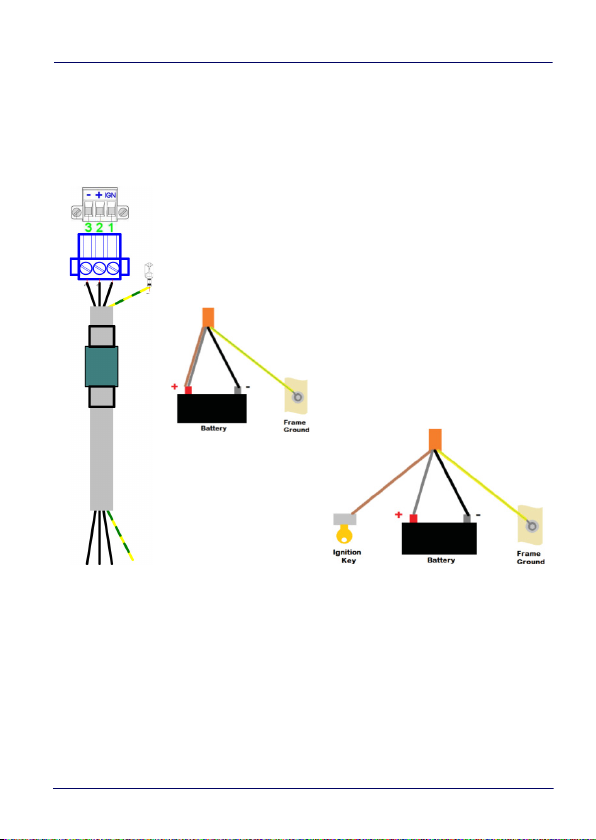
Appendix 1 - Docking Station
1. IGN Ignition grey
2. + positive charge brown
3. - negative charge black
4. GND Mass yellow/green
Autostart
Start with the ignition key
electrically isolated. The wires are already connected with the
provided cable. The wires of the 3-pole input connector must be
connected to DC Plus, DC minus and ignition. The ground (yellow green) is led in the cable and must be connected to the ground
contact.
User’s Manual 91
Page 98

Appendix 1 - Docking Station
Grounding
AC Power
Serial Connection
USB
Audio
Ethernet RJ45
Interfaces, Stationary Docking 110/230 VAC
Applies to accessories 94ACC0215, 94ACC0217, 94ACC0219,
94ACC0221, 94ACC0223, 94ACC0225.
AC connection
The Docking Station comes with a 3-pole plug on the left side. Use a
certified cable IEC 320 C13 to provide electrical connection to the
Docking Station. The internal power supply has a limit of 60W..
Use only certified or Datalogic approved cables.
CAUTION
92 TaskBook
Page 99

Appendix 1 - Docking Station
Connections available on Docking Station
Ethernet
The device has a 10/100MBit/s Ethernet interface.
Left LED off: No connection (no link)
Left LED on: Connection present, no activity
Left LED flashing: Connection present, activity present
Right LED off 10 Mbit/s
Right LED, yellow: 100 Mbit/s
The maximum cable length of 100m, as per specification, can be
limited depending on cable quality (CAT5, CAT6 etc.), cable laying or
external interference. A protected line must b e used.
USB
USB peripherals can be connected to the two USB 2.0 ports. A
maximum of 500 mA is available per connection. If the current
consumption is higher, the supply is automatically deactivated.
Audio connection (optional)
The cable cover loudspeaker can be connected to the audio
connector (optional) with a 3.5 mm jack plug. As soon as the
TaskBook is connected to the docking station, it automatically
switches to the playback device.
Serial connection (optional)
The device has a serial interface to connect devices with an RS 232
connection.
User’s Manual 93
Page 100

Appendix 1 - Docking Station
Grommet without
cable
Grommet for
cable up to 6 mm
Grommet for
cable from 6 mm
Correctly released grommets
(no overhang)
Incorrectly released grommets
(overhang present)
Cable Cover Installation
To ensure water and dust resistance, cables and empty
holes have to be fitted with the dedicated rubber grommet.
If the cables are not properly fastened or if any empty
CAUTION
Grommet Release
To correctly install the cable, please choose the appropriate
grommet. Remove the grommet from the bridge so that no overhang
remains.
holes haven't been protected, you may expose your Docking
Station to shock, short-circuit and other problems that may
damage the device. Without a cable cover, dust and
moisture can get into the device. Inspect the seal to ensure
it is undamaged and intact.
94 TaskBook
 Loading...