

Page 1
SG4 FIELDBUS
(SG4-xx-xxx-OP-x)
This Quick Reference Guide does not replace the Instruction Manual. Download
the Instruction Manual by reading the QR code here or at: www.datalogic.com.
Click on Support > Search by product and enter the SG4 family name, then
select your product from the dropdown list. Click on the Manuals & Technical
Literature link to download your Instruction Manual. The Instruction Manual must
be available at all times when installing and working with the product.
SAFETY INFORMATION
The following points must be observed for a correct and safe use of the safety light curtains of the SG4
FIELDBUS series:
The stopping system of the machine must be electrically controlled.
This control system must be able to stop the dangerous movement of the machine within the total machine stopping
time T as per cfr. 1.3 of the Instruction Manual and during all working cycle phases.
Mounting and connection of the safety light curtain must be carried out only by qualified personnel, according to the
indications included in the special sections (refer to cfr. 2; 3; 4; 5) and in respect to the applicable Standards.
The safety light curtain must be securely installed so that access to the dangerous zone is not possible without
interrupting the beams.
The personnel operating in the dangerous area must be well-trained and must have adequate knowledge of all the
operating procedures of the safety light curtain.
Please carefully read the instructions for the correct functioning before powering the light curtain.
Safety light curtains with infrared beams
QUICK GUIDE
Precautions to be observed for the choice and installation of the device
Make sure that the protection level assured by the SG4 device (Type 4) is compatible with the real danger
level of the machine to be controlled, according to EN ISO 13849-1 and EN 62061.
The dimension of the smallest object to be detected must be larger than the resolution level of the device.
The ESPE must be installed in a room complying with the technical characteristics indicated in cfr. “Technical data” of
the Instruction Manual.
Do not place the device near intense and/or flashing light sources and, in particular, close to receiving unit front surface.
The presence of intense electromagnetic disturbances could jeopardise device operation. This condition has to carefully
evaluated with the support of the Datalogic Technical service.
The operating distance of the device can be reduced in presence of smog, fog or airborne dust.
A sudden change in environment temperature, with very low minimum peaks, can generate a small condensation layer
on the lenses and so jeopardise functioning.
Reflecting surfaces near the safety light curtain light beam (above, under or lateral) can cause passive reflections that
can jeopardise functioning.
The safety device must be installed at a distance which is major or equal to the minimum safety distance S to ensure
that the operator can not reach the dangerous area until the moving dangerous object has been blocked by the ESPE.
The failure to respect the safety distance reduces or cancels ESPE the protection function. For more detailed
information about calculation of safety distance, please refer to the Instruction Manual.
1
Page 2
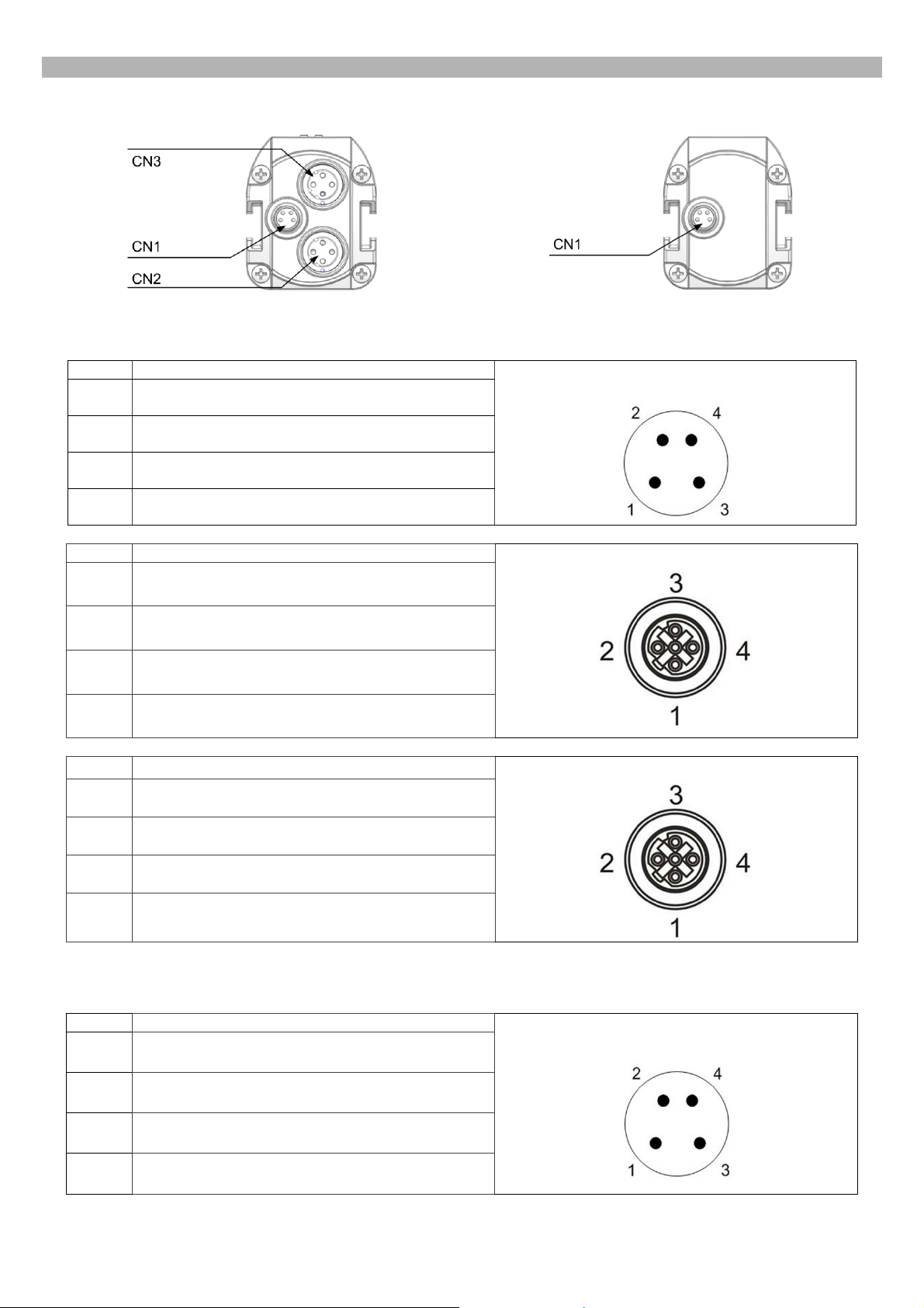
PIN-OUT AND CONFIGURATION PIN CONNECTION
Receiver (RX)
Emitter (TX)
For the receiver an M8 4-pin male connector is used for power supply, while two M12 D-coded female Ethernet
connectors provide dual port Ethernet Powerlink CN Node connection.
CN1 SIGNAL
1
2
24VDC (BROWN)
NOT USED (WHITE)
3
4
NOT USED (BLACK)
CN2 SIGNAL
1
2
3
4
TxD+, transmit data +
RxD+, receive data +
TxD–, transmit data –
RxD–, receive data –
CN3 SIGNAL
1
TxD+, transmit data +
0 VDC (BLUE)
POWER CONNECTOR
ETHERNET POWERLINK PORT1
ETHERNET POWERLINK PORT2
2
3
4
RxD+, receive data +
TxD–, transmit data –
RxD–, receive data –
For the emitter an M8 4-pin male connector is used for power supply.
CN1 SIGNAL
1
2
3
4
24VDC (BROWN)
NOT USED (WHITE)
0 VDC (BLUE)
NOT USED (BLACK)
2
POWER CONNECTOR
Page 3
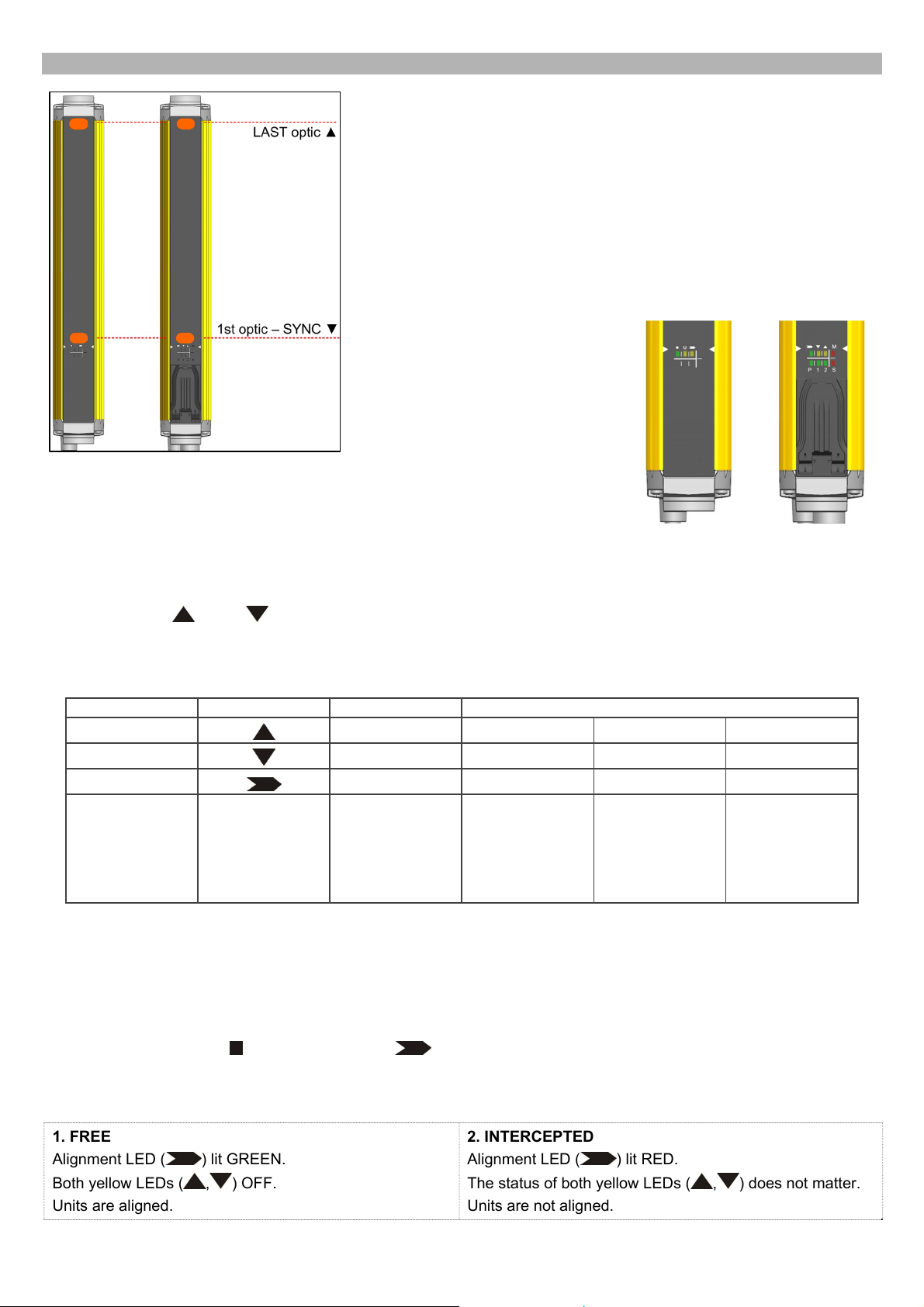
ALIGNMENT PROCEDURE
The alignment between the emitting and the receiving units is necessary to
obtain the correct operation of the light curtain.
A good alignment prevents outputs instability caused by dust or vibrations.
The alignment is perfect if the optical axes of the first and the last emitting
unit's beams coincide with the optical axes of the corresponding elements of
the receiving unit.
The beam used to synchronize the two units is the closest to the connector.
Thereon we refer to such beam as SYNC and to the last one as LAST.
When SYNC beam is not engaged all other beams scan it’s not possible,
thus it’s mandatory to have SYNC beam aligned and not intercepted.
A LED user Interface provides
indications about optic alignment
together with Fieldbus connection
status.
LEDs are clearly identified through
symbols or labels allowing their
immediate reading, independently of
bars directions; Find below a short description of LEDs indications about optical
alignment. For Fieldbus connection LEDs please refer to cfr. USER INTERFACE
AND DIAGNOSTICS.
The standard installation described hereinafter is the one shown in figure with the bar assembled with the connectors
pointing down.
Two yellow LEDs (
During standard operation, the LEDs indicate the safety light curtain optical alignment status, as shown in the table.
LED colour Symbol FREE INTERCEPTED
Yellow
Yellow
Red/Green
CORRECT alignment procedure
The light curtain alignment can be effected only after having completed the mechanical installation and the electrical
connections as described above.
Compare alignment results with those given in the following table:
Check the green LED (
Verify that the sensitive area from the safety light curtain is free;
Verify that one of the following conditions is present on the RX unit:
LAST, SYNC) on receiver unit facilitate the alignment procedure.
ALIGNMENT STATUS
OFF ON ON OFF
OFF ON OFF OFF
GREEN RED RED RED
SYNC ad LAST
beam engaged
No intercepted
Beams
UNITS not
aligned
SYNC engaged
LAST not
aligned
) and the yellow LED ( ) on the TX unit. If both ON, the emitter is running correctly;
Units correctly
aligned but at
least one
intermediate
beam
intercepted
1. FREE
Alignment LED (
Both yellow LEDs (
Units are aligned.
) lit GREEN.
, ) OFF.
2. INTERCEPTED
Alignment LED (
) lit RED.
The status of both yellow LEDs (
Units are not aligned.
3
, ) does not matter.
Page 4

Continue with the following steps to switch from condition 2 to condition 1:
1. Keep the receiver in a steady position and regulate the emitter until the yellow LED (
shows the effective alignment of the first synchronization beam.
2. Rotate the emitter, pivoting on the lower optics axis, until the yellow LED (
if no other beam is intercepted Alignment LED (
3. Delimit the area in which the LED
the second unit - then place both units in the centre of this area.
Ensure that the green LED
Fix the two units firmly using brackets.
is steady GREEN through some micro adjustments - for the first and then for
) should turn GREEN.
is steady ON.
LAST) is OFF. Under these conditions,
SYNC) is OFF. This condition
This verification shall be made with the special cylindrical “Test Piece” having a size suitable to the resolution of the
A daily test is recommended.
Verify that the green LED on the RX unit is ON ( ) and beams are not interrupted, then verify that the red
LED turns ON if even one single beam is interrupted (condition where an object has been detected).
device used.
Passing the Test Piece along the whole sensitive area and at any distance from the two
units, the red LED (
) shall be always ON and never change status.
DEVICE DESCRIPTION FILE
Importing device in B&R automation studio
In order to make the light curtain available in Automation Studio it’s necessary to import the description files in Automation
Studio.
1. Select Tools -> Import Fieldbus Device
Step 1 - Importing the device
4
Page 5

For SG4 FIELDBUS Series light curtain different description files are available depending on specific light curtain model,
please refer to table below:
Model Length (mm) Description Files
Base
(SG4-xx-xxx-OP-B)
Advanced up to 600mm
(SG4-xx-xxx-OP-A)
Advanced from 750mm to 1800mm
(SG4-xx-xxx-OP-A)
150-1800
150-600
750-1800
FFFF000D-SG4-x-x-OP-B.xdd
SG4-x-x-OP-B.xosdd
FFFF000D-SG4-14_30-15_60-OP-A.xdd
SG4-14_30-15_60-OP-A.xosdd
FFFF000D-SG4-14_30-75_180-OP-A.xdd
SG4-14_30-75_180-OP-A.xosdd
2. Select first the file with extension .xosdd related to the device you want to import.
Step 2 - Importing the device
3. Select the file with extension .xdd according to the one selected above.
Step 3 - Importing the device
5
Page 6

Once imported, the device will be present in Automation Studio Hardware Catalog, ready to be used in the project.
Just search for the right device and drag&drop.
SG4 FIELDBUS devices in Automation Studio Hardware Catalog
SETTING DEVICE ADDRESS
In Automation Studio right-click on SG4 FIELDBUS device and select “Change node number”, set the address from 1 to
240.
Select EPL device address in AutomationStudio
On device choose same address by setting the two rotary switches under the blue plastic flap.
Use a proper tool as a little flat-head screwdriver to open the flap and set the switches.
EPL address in Automation studio is visualized in decimal format, while the rotary
switches are hexadecimal type.
Select EPL device address on the device
6
Page 7

USER INTERFACE
USER INTERFACE AND DIAGNOSTICS
Receiver
Emitter
In the bottom side of the light curtain a user interface with 8 LEDs helps customer to check the status of the light curtain
and the POWERLINK / openSAFETY variation.
Receiver (RX):
LED COLOR FUNCTION NORMAL OPERATION FUNCTION ERROR
BEAM STATUS
M
Red/Green
Yellow
Yellow
Red
Red ON ► At least one beam intercepted
Green ON ► All beams free
SYNC BEAM
ON ► First beam intercepted or not aligned
LAST BEAM
ON ► Last beam intercepted or not aligned
MASTER uP STATUS
OFF ► Normal operation
Blinking ►
Boot Pre-op
Red ON
Blinking
uP ERROR
OPTIC ERROR
openSAFETY ERROR
ON ► Error ON uP MASTER
S
P
1
2
Red
Red/Green
Green
Green
SLAVE uP STATUS
see LED S
ETHERNET POWERLINK STATUS
Green ON ► normal operation
Green blinking: pre-op
Green double-blinking: Firmware Update in
progress
EPL PORT 1 LINK
ON ► there is a link
Blinking ► there is activity on this link
EPL PORT 2 LINK
ON ► there is a link
Blinking ► there is activity on this link
ON ► Error ON uP SLAVE
Red ON ► Ethernet Powerlink
Error
no error indicator
no error indicator
Emitter (TX):
LED COLOR FUNCTION NORMAL OPERATION FUNCTION ERROR
U
Green
Yellow - Blinking
Yellow
POWER
Green ON ► Power ON, Normal Operation
EMISSION
ON ► Emission active
Red ON
OPTIC ERROR
U uP ERROR
U
openSAFETY ERROR
7
Page 8

ORIGINAL INSTRUCTIONS (ref. 2006/42/EC)
CE Compliance
CE marking states the compliance of the product with essential requirements listed in the applicable European directive.
Since the directives and applicable standards are subject to continuous updates, and since Datalogic promptly adopts
these updates, therefore the EU declaration of conformity is a living document. The EU declaration of conformity is
available for competent authorities and customers through Datalogic commercial reference contacts. Since April 20th,
2016 the main European directives applicable to Datalogic products require inclusion of an adequate analysis and
assessment of the risk(s). This evaluation was carried out in relation to the applicable points of the standards listed in the
Declaration of Conformity. Datalogic products are mainly designed for integration purposes into more complex systems.
For this reason it is under the responsibility of the system integrator to do a new risk assessment regarding the final
installation.
Warning
This is a Class A product. In a domestic environment this product may cause radio interference in which case the user
may be required to take adequate measures.
Datalogic S.r.l.
Via S. Vitalino 13 - 40012 Calderara di Reno - Italy
Tel: +39 051 3147011 - Fax: +39 051 3147205 - www.datalogic.com
Helpful links at www.datalogic.com: Contact Us, Terms and Conditions, Support.
The warranty period for this product is 36 months. See General Terms and Conditions of Sales for further details.
© 2017 - 2018 Datalogic S.p.A. and/or its affiliates ALL RIGHTS RESERVED Without limiting the rights under copyright, no part of
this documentation may be reproduced, stored in or introduced into a retrieval system, or transmitted in any form or by any means, or
for any purpose, without the express written permission of Datalogic S.p.A. and/or its affiliates. Datalogic and the Datalogic logo are
registered trademarks of Datalogic S.p.A. in many countries, including the U.S.A. and the E.U. All other trademarks and brands are
property of their respective owners. Datalogic reserves the right to make modifications and improvements without prior notification.
821004283 Rev. C
8
 Loading...