

Page 1
Rhino™ II
Rugged Vehicle Mount Computer
User’s Manual
Page 2

Datalogic S.r.l.
Via San Vitalino 13
40012 Calderara di Reno (BO)
Italy
Tel. +39 051 3147011
Fax +39 051 3147205
©2017 Datalogic S.p.A. and/or its affiliates
All rights reserved. Without limiting the rights under copyright, no part of this
documentation may be reproduced, stored in or introduced into a retrieval system, or
transmitted in any form or by any means, or for any purpose, without the express
written permission of Datalogic S.p.A. and/or its affiliates. Owners of Datalogic
products are hereby granted a non-exclusive, revocable license to reproduce and
transmit this documentation for the purchaser's own internal business purposes.
Purchaser shall not remove or alter any proprietary notices, including copyright
notices, contained in this documentation and shall ensure that all notices appear on
any reproductions of the documentation.
Should future revisions of this manual be published, you can acquire printed versions by
contacting your Datalogic representative. Electronic versions may either be downloadable
from the Datalogic website (www.datalogic.com) or provided on appropriate media. If you
visit our website and would like to make comments or suggestions about this or other
Datalogic publications, please let us know via the "Contact Datalogic" page
.
Disclaimer
Datalogic has taken reasonable measures to provide information in this manual that is
complete and accurate, however, Datalogic reserves the right to change any
specification at any time without prior notice. Datalogic and the Datalogic logo are
registered trademarks of Datalogic S.p.A. in many countries, including the U.S.A. and
the E.U.
Rhino is a trademark of Datalogic S.p.A. and/or its affiliates.
The Bluetooth® word mark and logos are owned by Bluetooth SIG, Inc. and any use of
such marks by Datalogic Mobile, Inc. is under license.
Wi-Fi is a registered certification mark of the Wi-Fi Alliance.
Microsoft, Windows Embedded Standard 7, Windows 10 IoT and the Windows logo are
registered trademarks of Microsoft Corporation in the United States and/or other
countries.
All other brand and product names may be trademarks of their respective owners.
Patents
See www.patents.datalogic.com
for patents list.
Page 3

User’s Manual i
Table of Contents
Introduction ....................................................................... 1
Conventions ..................................................................................1
Product Presentation ..................................................................2
Available Models ..........................................................................3
Out of the Box ...............................................................................4
General View .................................................................................5
Front View .............................................................................5
Back View ..............................................................................6
Bottom View .........................................................................7
Accessories ...................................................................................8
Getting Started .................................................................. 9
Power On .......................................................................................9
Desktop Window ....................................................................... 10
Adjusting the Screen Brightness ............................................. 12
Adjusting the Volume ............................................................... 12
Using the Accessories ............................................................... 13
Using an External Keyboard ............................................. 13
Using a Barcode Scanner .................................................. 13
Resetting the Terminal ............................................................. 15
Warm Boot ......................................................................... 15
Clean Boot (WEC7 Only) .................................................... 15
LED Indicators (WES7/Win10IoT) ............................................ 16
LED Indicators (WEC7) .............................................................. 16
Rhino II Configuration.................................................... 17
Startup/Shutdown Modes ....................................................... 17
Page 4

ii Rhino™ II
Front Panel Keys ........................................................................19
Screen Blanking ..........................................................................22
Keyboard Configuration File .....................................................23
Section [Common] ..............................................................23
Section [VolumeTouchCtrl] ................................................26
Section [Fonts] ...................................................................26
Section [Keys] .....................................................................28
Section [Keyboard_XX] ......................................................30
Section [Execute] ................................................................36
System-Admin and Password-Keyboard ...............................37
Password Keyboard ...........................................................38
SysAdmin-Menu Keyboard ...............................................41
Virtual Keycodes ........................................................................44
Special Function Codes .....................................................44
General Keyboard Codes ...................................................46
Upgrading the Rhino II WEC7 Firmware ..................................49
Datalogic Applications.................................................... 51
Desktop Configuration Utility (DXU) .........................................51
How DXU Works .................................................................52
Installation ..........................................................................53
Controls ...............................................................................55
Simplified Deploy ...............................................................61
Tasks ...................................................................................73
Configuring SureLock and SureFox ..................................99
Command Line DXU Execution ...................................... 102
Datalogic Desktop Utility ........................................................ 103
Administrative Options (Admin tab) ............................. 104
Locked Web Browser Options (LockedWeb Tab) ......... 108
Status Icons Options (Status Tab) ................................. 113
Windows Controls (Win Tab) .......................................... 114
AppSelector Options (AppSelect Tab) ............................ 116
Page 5

User’s Manual iii
App Selector (Application Selector) ....................................... 119
Locked Web Browser .............................................................. 120
Locked Web Browser Special Metatags ....................... 121
General Metatag Comments .......................................... 121
PAL and PAL Communicator .................................................. 126
Setting Up Serial Scanning ..................................................... 127
Communications .......................................................... 129
Setting Up Ethernet Communications .................................. 129
Setting Up 802.11 Radio Communications ........................... 130
Setting Up Bluetooth Radio Communications ..................... 130
Wireless and Radio Frequencies Warnings ......................... 131
Technical Features ....................................................... 135
Technical Data ......................................................................... 135
Troubleshooting the Rhino II ...................................... 139
Problems While Operating the Rhino II ................................ 139
Problems with Wireless Connectivity ................................... 140
Maintenance ................................................................. 143
Cleaning the Device ................................................................. 143
Ergonomic Recommendations .............................................. 143
Safety and Regulatory Information............................ 145
General Safety Rules ............................................................... 145
Power Supply ........................................................................... 146
Marking and European Economic Area (EEA) ...................... 147
Simplified EU Declaration of Conformity .............................. 147
Statement of Compliance ....................................................... 147
Information for the User ................................................ 149
FCC ID/IC Warning ................................................................... 150
Exposure to Radio Frequency Radiation .............................. 151
Radio Technologies and Frequency Bands ........................... 152
WEEE Compliance ................................................................... 153
Reference Documentation........................................... 155
Page 6

iv Rhino™ II
Support Through the Website ............................................... 155
Technical Support through email or phone. ......................... 155
Warranty Terms and Conditions ........................................... 155
Glossary......................................................................... 157
Page 7

User’s Manual 1
Introduction
Conventions
This manual uses the following conventions:
"Mobile computer", "Vehicle Mount Computer", "VMC" and
"Rhino II" refer to Rhino II vehicle mount computer.
WEC7 refers to the Windows Embedded Compact 7 operating
system.
WES7 refers to the Windows Embedded Standard 7 Pro operatingy
system.
Win10 IoT refers to the Windows 10 IoT operating system.
The label artworks may be only a draft. Refer to the product labels
for more precise information.
Page 8

Introduction
2Rhino™ II
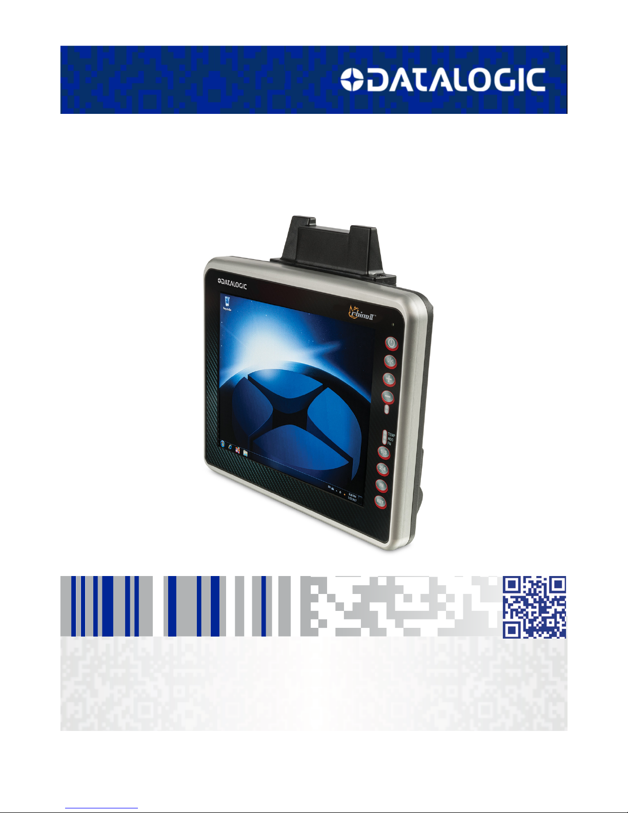
Product Presentation
The Rhino II vehicle mount computers, available in both 10" and 12"
display sizes, set the standard for ruggedness in the warehouse. A
sealed design tested to IP65/IP67 ensures operation in the toughest
environments. A dedicated freezer-rated model with integrated
display heater allows use in and out of cold storage. The capacitive
touch models feature 3 mm anti-glare armored glass, while still
allowing use of gloves.
Tailored for warehouse management, the Rhino vehicle computer
increases productivity through reduced errors during receiving,
putaway, picking and shipping activities. Adding a handheld bar code
scanner such as Datalogic’s PowerScan™ allows for quick data entry
and location confirmations.
The Rhino vehicle computer is equipped with an internal isolated
power supply, ignition sense to automatically control the power, and
an optional battery backup for the ultimate protection against data
loss. The Rhino vehicle computer fits different mounting and space
constraints. Mounting options include various brackets and RAM
mounts for the vehicle computer along with ABCD or QWERTY
external keyboards. A dedicated software keyboard includes a
multitude of layouts and languages, adapting the Rhino computer to
a minimum footprint and global applications.
The Rhino II computer offers a choice of Windows Embedded
Compact 7 (WEC7), Windows Embedded 7, or Windows 10 IoT
Enterprise operating systems. Included are various Datalogic Utilities
and on the WEC7 models, Wavelink® Avalanche™ and Terminal
Emulation are pre-loaded and pre-licensed, allowing the Rhino
computer to maximize return-on-investment (ROI) through easy
deployment, device and maintenance management.
Page 9

Introduction
User’s Manual 3
Available Models
The Rhino II is available in different models depending on the
options it is equipped with. All options are listed below:
• Internal power supplies: 12-24VDC and 24-48VDC
• Screen sizes: 10" and 12"
• Operating Systems: Windows Embedded Compact 7, Windows
Embedded 7 Pro, Windows 10 IoT and Android 6
• Freezer Model (WEC7 10" only)
For further details about the Rhino II models refer to the web site:
http://www.datalogic.com.
The currently available models are:
• 943200008 10" Rhino II Win10 IoT 12VDC
• 943200006 10" Rhino II WES7 12VDC
• 943200004 10" Rhino II WEC7 12VDC
• 943200007 10" Rhino II Win10 IoT 24-48VDC
• 943200005 10" Rhino II WES7 24-48VDC
• 943200003 10" Rhino II WEC7 24-48VDC
• 943200002 10" Freezer Rhino II WEC7 12VDC
• 943200001 10" Freezer Rhino II WEC7 24-48VDC
• 943200022 12" Rhino II Win10 IoT 12VDC
• 943200020 12" Rhino II WES7 12VDC
• 943200018 12" Rhino II WEC7 12VDC
• 943200021 12" Rhino II Win10 IoT 24-48VDC
• 943200019 12" Rhino II WES7 24-48VDC
• 943200017 12" Rhino II WEC7 24-48VDC
Page 10

Introduction
4Rhino™ II
Out of the Box
The Rhino II package contains:
• Rhino II vehicle mount computer
•Installation guide
• Power cable length = 2.9m (9.5')
• Bag - 4 mounting screws and washers for use with RAM mounts
• Bag - rubber cable slot seals and cable ties
• Bluetooth USB adapter (only for WES7 and Win10 IoT models)
• Safety & Regulatory Addendum
• Wavelink Avalanche Insert (WEC7 models only)
• Wavelink Terminal Emulation insert (WEC7 models only)
• End User License Agreement (EULA) Sheet
Remove all the components from their packaging; check their
integrity and compare them with all the packing documents.
CAUTION
Keep the original packaging for use when sending products
to the technical assistance center. Damage caused by
improper packaging is not covered under the warranty.
Page 11
Introduction
User’s Manual 5
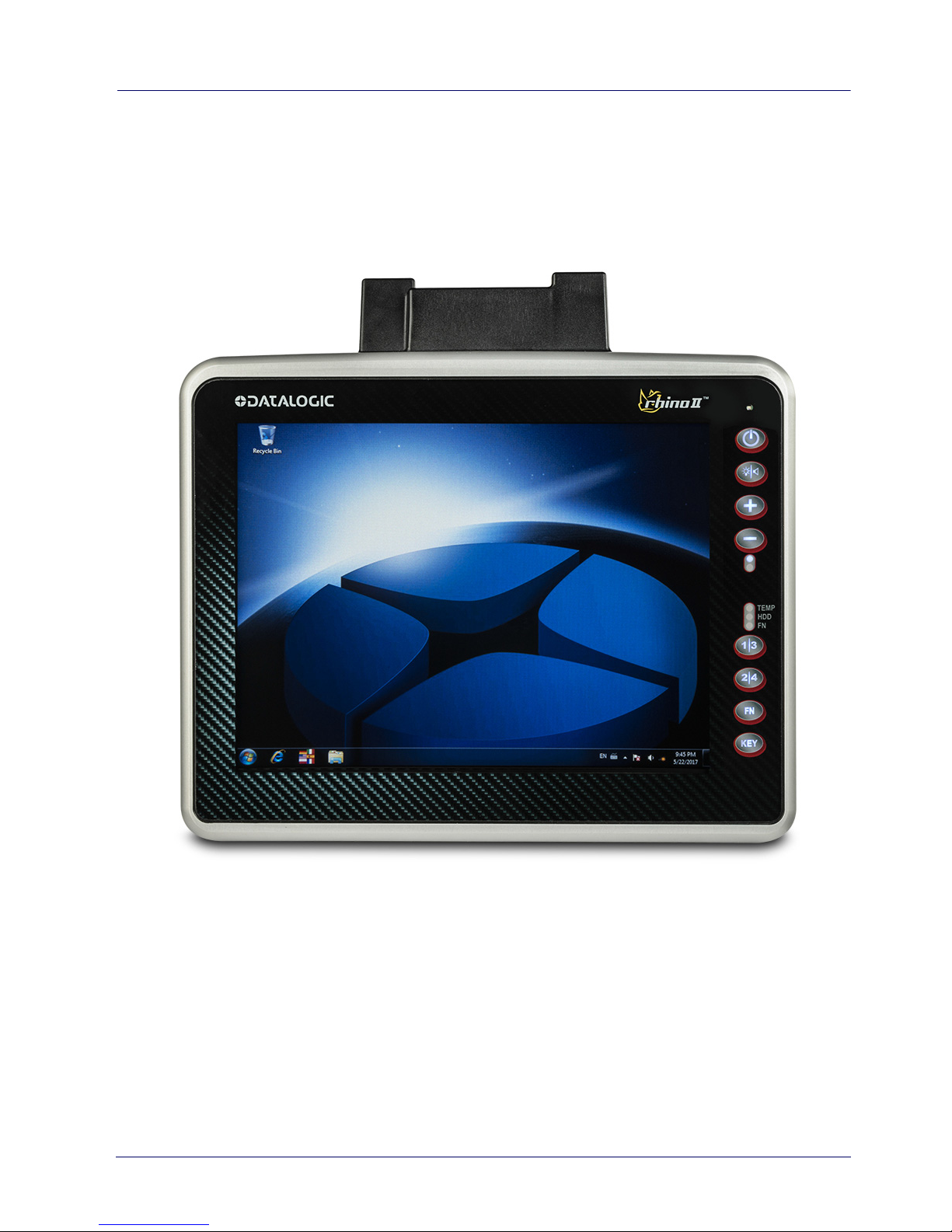
General View
Front View
Page 12
Introduction
6Rhino™ II
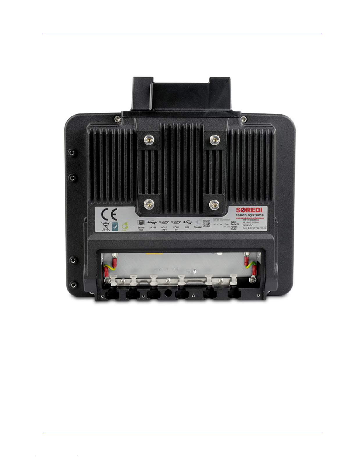
Back View
Page 13
Introduction
User’s Manual 7
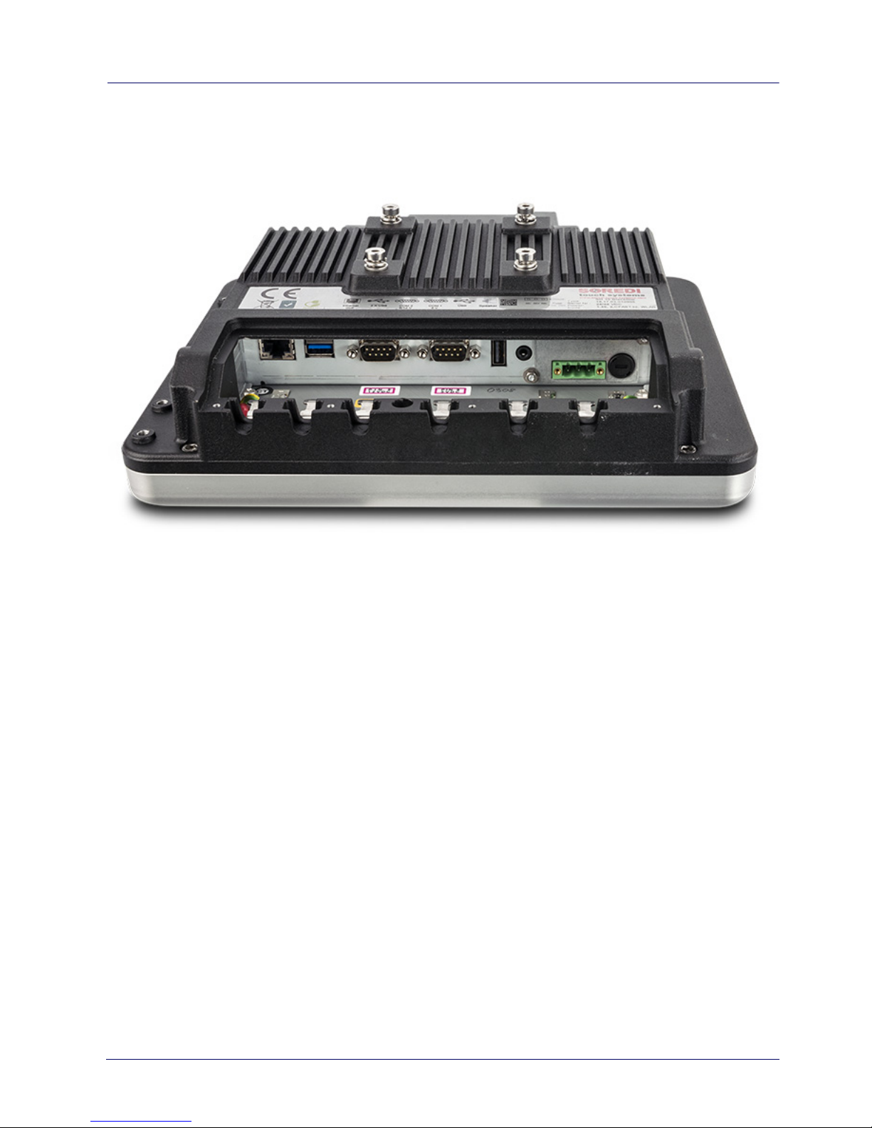
Bottom View
Page 14

Introduction
8Rhino™ II
Accessories
Keyboards
95ACC1330 External Keyboard QWERTY
95ACC1374 Compact Keyboard, External, QWERTY
95ACC1331 External Keyboard, ABCD
Cable Covers
94ACC0173 Cable Cover, 5 poles, w 2.9m power cable (for quick
disconnect)
94ACC0160 Speaker Cable Cover
Mounts
94ACC0172 Fixed Mounting Bracket, 130 degree
94ACC0155 Keyboard External Mounting Bracket
94ACC0175 Quick Change V Mount
94ACC0035 RAM Mount 4" rail base
94ACC0034 RAM Mount with round base
94ACC0156 Scanner holder
94ACC0154 Vehicle Mounting Bracket, 10 degree
Power Supplies
94ACC1061 AC/DC Power Brick
94ACC0165 DC Power Cable, 2.9M
94ACC0041 External 72-80 VDC Voltage Converter
CAUTION
Use only a Datalogic approved power supply and cables.
Use of an alternative power supply will invalidate any
approval given to this device and may be dangerous.
Page 15

User’s Manual 9
Getting Started
Power On
The Rhino II turns on based on its current startup mode settings
(see Startup/Shutdown Modes on page 17).
As soon as the VMC is on, the desktop will appear on the screen.
Wait a few seconds before starting any activity so that the mobile
computer completes its startup procedure.
The VMC shuts down based on its current shutdown mode settings
(see Startup/Shutdown Modes on page 17).
Page 16
Getting Started
10 Rhino™ II
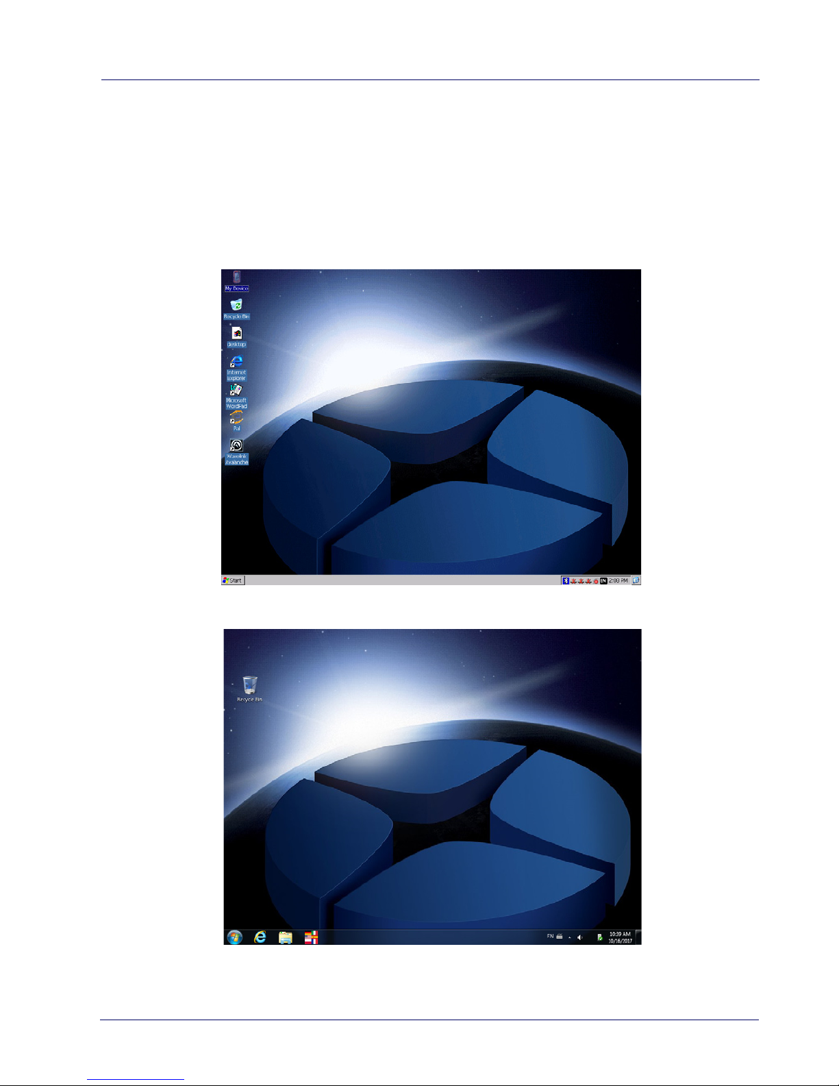
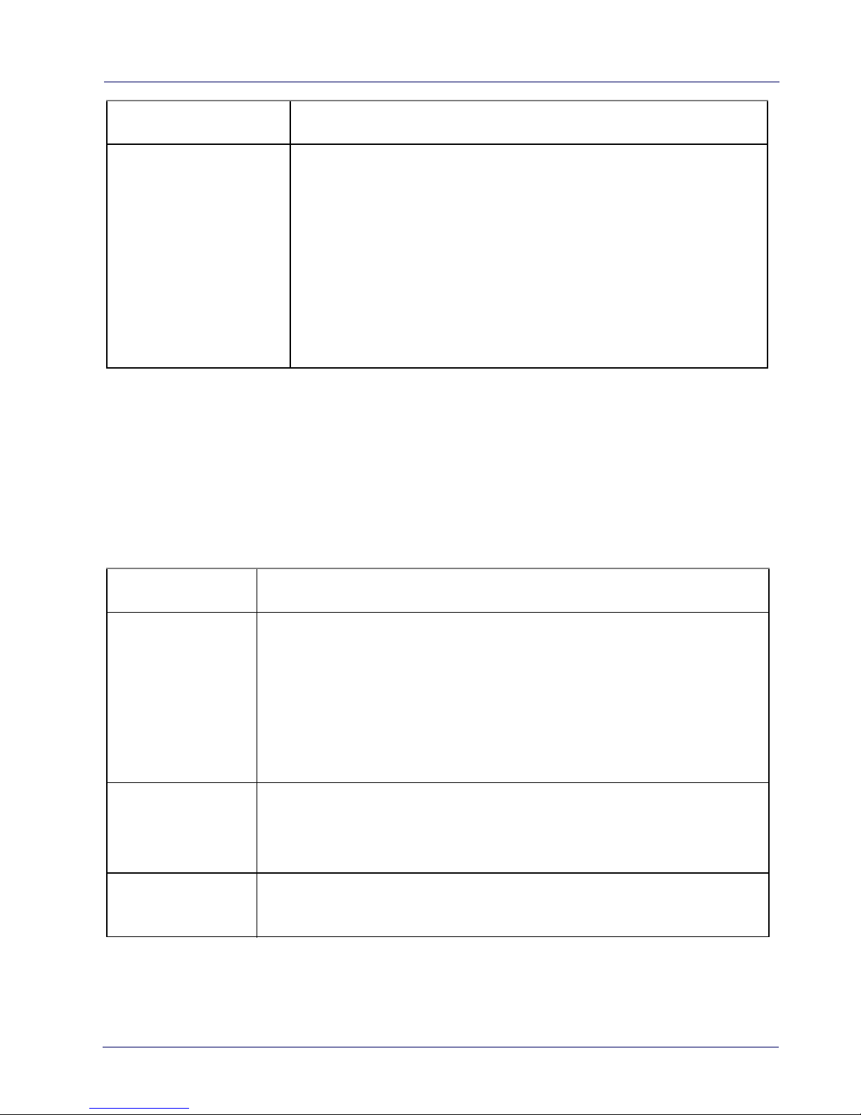
Desktop Window
As soon as the mobile computer is on, the WEC7, Win10 IoT or WES7
desktop appears on the screen. Wait a few seconds before starting
any activity so that the mobile computer completes its startup
procedure.
WEC7 Desktop
WES7 Desktop
Page 17

Getting Started
User’s Manual 11
Win10 IoT Desktop
Page 18

Getting Started
12 Rhino™ II
Adjusting the Screen Brightness
To adjust the screen brightness:
• Press the + button to increase the brightness.
• Press the - button to decrease the brightness.
Adjusting the Volume
To adjust the volume, press the FN button first
• Press + button to increases the volume. The computer will play
the Default Sound at the new volume setting.
• Press the - button to decreases the volume. The computer will
play the Default Sound at the new volume setting.
Page 19

Getting Started
User’s Manual 13
Using the Accessories
Using an External Keyboard
You can use many standard USB compatible keyboards. Datalogic
recommends the use of a sealed/ruggedized key-board:
• Sealed/rugged keyboards are available from Datalogic
including: full sized QWERTY, ABCD, or mini QWERTY USB
keyboards
• The keyboard attaches to one of the two USB ports on the
Rhino. It is automatically detected and prepared for use.
For information on installing the rugged keyboard and its mount,
see the Rhino II Installation manual.
Using a Barcode Scanner
Your can use either a USB or serial scanner with the Rhino II
computer. Be sure to order your scanner with the ap-propriate
cable.
Connecting a USB Scanner
1. Remove the cable compartment cover plate.
2. Plug the cable into one of the USB ports. Depending on the
scanner you are attaching, you may hear a series of beeps and
the Good Read light may flash.
3. Choose a rubber plug for the scanner cable with the appropriate
sized hole. Run the cable through the hole, then insert the plug
into a slot on the terminal.
4. If desired, use a nylon tie-wrap to secure the cable to the post
inside the cable compartment. Replace the cable compartment
cover
Page 20

Getting Started
14 Rhino™ II
5. The scanner should now be ready for use. To test, run any
program that accepts keyboard input and perform a scan. If the
data does not display in the application, consult the user manual
for the scanner.
Connecting a Serial Scanner
COM1 provides 5VDC on pin 9, COM2 provides 12 VDC. Verify which
voltage the scanner requires and connect to the appropriate COM
port.
1. Remove the cable compartment cover plate.
2. Plug the cable into the desired COM port. Depending on the
scanner you are attaching, you may hear a series of beeps and
the Good Read light may flash.
3. Choose a rubber plug for the scanner cable with the appropriate
sized hole. Run the cable through the hole, then insert the plug
into a slot on the terminal.
4. If desired, use a nylon tie-wrap to secure the cable to the post
inside the cable compartment. Replace the cable compartment
cover
5. Configure the serial wedge program for the selected port and
baud rater. See Setting Up Serial Scanning on page 127. The
scanner should now be ready for use. To test, run any program
that accepts keyboard input and perform a scan. If the data does
not display in the application, consult the user manual for the
scanner.
Page 21

Getting Started
User’s Manual 15
Resetting the Terminal
There are two reset methods for the Rhino II.
A warm boot terminates an unresponsive application and clears the
working RAM, but preserves the file system. The Registry is restored
from persistent memory if available or returned to factory default.
A clean boot restores the Rhino II to a clean configuration: both the
Registry and the file system returns to a clean status that conforms
to factory default (WEC7 only).
Warm Boot
To perform a warm boot, power down the terminal.
Clean Boot (WEC7 Only)
To perform a clean boot, do the following steps:
1. Launch a DOS prompt in Administrator mode
2. Change directory to \Windows
3. Run CleanBoot.cmd. CleanBoot can take up to 5 minutes, please
wait for the VMC to reboot.
Page 22

Getting Started
16 Rhino™ II
LED Indicators (WES7/Win10IoT)
The LEDs illuminate to indicate various functions or errors on the
reader. The following tables list these indications.
LED Indicators (WEC7)
LED Status Description
Top Blue (Top) Solid Wi-Fi connected
Blue (Center) - Not used
Blue (Bottom) Solid FN toggled on
Red Solid High Temperature Warning
Yellow Solid HD Access
LED Status Description
Blue Solid FN toggled on
Red Solid High Temperature Warning
Yellow Solid HD Access
Page 23

User’s Manual 17
Rhino II Configuration
Startup/Shutdown Modes
The Rhino II has 3 modes of controlling Startup and Shutdown. The
mode is set by commands in the "\Utilities\UtilConfig.cfg" file. Each
mode controls how the Ignition Sense power connector wire (IGN)
and the Rhino II’s front panel Power button (PWR) work together. In
the default mode (mode 1), IGN must be at a voltage greater than 10
VDC and PWR must be pressed and held for a specified period to
power up the VMC. Shutting down in this mode may be
accomplished by removing the positive voltage from IGN or pressing
the PWR button, either must be for a specified time to shutdown.
The other common mode (mode 0) allows IGN or PWR to control the
Startup/Shutdown. In this mode connecting IGN to positive voltage
will power up the VMC, and disconnecting it will power down.
Similarly powering up via PWR then pressing PWR again will power
back down. If using PWR to control the VMC in this mode, IGN
should NOT be switched or tied to + power. When using this mode
you should either be exclusively using IGN to control the VMC, or
PWR but not mixing the two.
NOTE: If the VMC is powered up via IGN, but powered down via PWR,
it will immediately begin to power back up.
The final mode (mode 3) is seldom used. In this mode, the VMC will
power up anytime there is power applied. Both IGN and PWR are
ignored in this state.
Page 24

Rhino II Configuration
18 Rhino™ II
When the VMC is being powered down by IGN, it will typically display
a countdown screen advising the user the remaining time before the
terminal shuts down. The shutdown time as well as whether the
countdown is displayed are both controlled by the configuration file.
Configuration (in \Utilities\UtilConfig.cfg):
• PowerOnMode=1 Sets the Startup/Shutdown mode.
- 0 = IGN or PWR
-1 = IGN and PWR
-3 = AutoOn
• IgnOffDialog=01 Display the shutdown timer window
when IGN is turned off.
-0 = Do not display the window.
- 1 = Display the shutdown timer window.
• IgnOffDlgType=2 Size of the shutdown timer window if
enabled.
- 0 = Full screen display, no user interaction is allowed (not
recommended).
- 1 = Medium size display, user may move the window and
interact with the system.
- 2 = Small size display, user may move the window and
interact with the system.
• IgnStartTimeSec=3 Seconds after IGN goes high before the
VMC begins booting.
• IgnOffDelayTimeSec=15 Seconds after IGN disconnects before
the VMC shuts down.
• DelayPowerKey=100 Milliseconds PWR must be pressed
before the VMC begins booting.
Page 25

Rhino II Configuration
User’s Manual 19
Front Panel Keys
There are four programmable buttons on the right side of the
terminal. The programming is set by command lines in the
"\Utilities\UtilConfig.cfg" file. The buttons are PWR, 1/3, 2/4 and
KEY. The 1/3 and 2/4 buttons are actually programmable as two
keys each, giving a total of six available keys. In normal operation
these will generate the specified 1 key and 2 key values. If the FN
key is pressed to set the VMC into function mode, pressing the same
keys will generate the specified 3 key and the 4 key values. When
FN is pressed, the blue function LED with display. Pressing 1, 2 or FN
will turn the LED off and turn off function mode. By default, the
buttons have the following functions:
• PWR – Starts & shutdowns the terminal depending on the
current Startup/Shutdown mode.
•1 – Up arrow.
•2 – Down arrow.
•3 – Escape key.
•4 – Return key.
• KEY – Display/remove the soft keyboard from the screen.
Normally the PWR and KEY buttons should not be reprogrammed,
but they are available if required.
Configuration (in \Utilities\UtilConfig.cfg). The listed values are the
default values from the factory. Setting PWR and KEY to blank
causes them to execute Startup/Shutdown and Softkeyboard
respectively. The VK values for each key are listed in the
SoftKeyboard section of this document. Multiple values can be
entered for a key by using comma to separate the values. For
example, the definition Frontkey_S1=#EXT=VK_TAB,VK_RETURN
would cause the S1 key to transmit tab, then a return key.
•Frontkey_PWR=
Page 26

Rhino II Configuration
20 Rhino™ II
• Frontkey_S1=#EXT=VK_UP
• Frontkey_S2=#EXT=VK_DOWN
• Frontkey_S3=#EXT=VK_ESCAPE
• Frontkey_S4=#EXT=VK_RETURN
• Frontkey_KEY=
The S1-S4 keys can also be used to launch executables. Just give the
fully qualified name after the equal sign. For example:
Frontkey_S1=\Windows\pword.exe
will launch the WordPad program when the 1 key is pressed.
The Rhino II also provides the ability to lock the individual front panel
keys. There are two keywords to control the state of the keys when
the function mode is off (HWKeyLockFNOff) and when the function
mode is on (HWKeyLockFNOn). Each of the keywords is an 8 bit
mask, using one bit each to control the individual keys. Bits 0-7 are:
•PWR (1)
•BL (2)
•+ (8)
• - (16)
• S1 (32)
• S2 (64)
• FN (128)
•KEY (256)
Setting the specific bit to a 1 will lock the respective key. For
example, setting HWKeyLockFNOff=66 would disable the BL (2) and
S2 (64) buttons when the function mode is not set. Setting
HWKeyLockFNOn=256 would disable the KEY (256) button when the
function mode is set.
Page 27

Rhino II Configuration
User’s Manual 21
NOTE
Be aware that if you are attempting to control the PWR
button, you can lock the Rhino II. Disabling the PWR button
at the same time you have the startup mode set to IGN and
PWR will block the Rhino II from being able to be powered
up.
Page 28

Rhino II Configuration
22 Rhino™ II
Screen Blanking
The Rhino II has the ability to blank the screen when positive voltage
is applied to a designated COM port pin. This is typically used to blank
the screen when a vehicle is in motion, a requirement is some
countries. For the Rhino II, an external sensor must be used that will
either provide a positive voltage when the vehicle moves, or closes a
relay in the same circumstance. If using a relay, then the positive
voltage from pin 9 of the selected COM port should be wired as input
to the relay. The output from the sensor or relay should be wired to
pin 1 (DCD) or pin 6 (DSR) of the selected COM port. The screen
blanking cable from Datalogic (p/n 94ACC0157) is wired to pin 9 (pink)
and pin 6 (grey).
Configuration (in \Utilities\UtilConfig.cfg):
Locate (or add) the line ScreenBlankBits=X in the [General] section of
the file. X should be set to the appropriate value from the list:
• 1 – COM1: DCD (pin 1)
•2 – COM1: DSR (pin 6)
• 4 – COM2: DCD (pin 1)
•8 – COM2: DSR (pin 6)
Deleting the ScreenBlankBits line from the cfg file will turn off screen
blanking.
Page 29

Rhino II Configuration
User’s Manual 23
Keyboard Configuration File
The Configuration file is a text file built in sections to provide the
definitions for the keyboard layouts. Comments can be marked at
beginning of a line with a semicolon (;).
Section [Common]
In this section general settings will be defined.
Certain settings can be overridden explicitly within the definition
sections of the actual keyboard data for the respective keyboard.
These settings are explained separately in a 2nd table.
General Settings
Keyname Parameter – Info
ImagePath
Directory name for all used Bitmaps within this Cfg. The
specified directory is always searched in the list of the
specified CFG file. A complete path specification is not
supported.
KBShowOnStart=X
With this parameter a fixed specified Keyboard will be
shown automatically after the start. X stands for the
Keyboard-Number from the Keyboard-Config. For
example, KBShowOnStart=1 always shows the
Keyboard from the Cfg-Section [Keyboard_01].
If no keyboard should be visible at the start, X can be set
to a invalid Number, e.g. 100 or the parameter can be
left out.
SysAdminPwdKB
Specifies the defined keyboard number for a password
keyboard.
SysAdminMenKB
Specifies the defined keyboard number for a
SysAdmin-Menu-Keyboard.
Page 30
Rhino II Configuration
24 Rhino™ II
Pre Settings for Keyboards
These settings apply here for all following keyboard definitions,
however, they can be explicitly overridden in the keyboard definition
for special cases.
RotateScreen
With this you can specify the angle of rotation which is
set by the key function VKX_KB_SCRROTATE. A
maximum of four values are possible
(0=Default-Systemstartup, 1=90°, 2=180°, 3=270°). For
rotation minimum 2 values must be defined. For
example RotateScreen=0,1 is defined, it will be toggled
between these two angles. If the Key isn’t existing or
empty, all 4 values will be set one after another.
Keyname Parameter – Info
FrameImage
BitmapName.bmp,FrameSizeX,FrameSizeY
Bitmap for the Keyboard-Frame and to set the background.
FrameSizeX defines the left and right distance to the keys.
FrameSizeY defines the upper and lower distance to the
keys.
A keyboard without frame can be defined.
TitleBar
0 (=Default)
With 1 the Windows title bar can here be activated for
special cases.
Title
Here, any string can be defined as titles for TitleBar, e.g.
"Soft Keyboard".
Keyname Parameter – Info
Page 31

Rhino II Configuration
User’s Manual 25
AlphaValue
0 (=Default – no Transparency)
Here values of 10 (almost completely transparent / invisible)
to 250 (almost opaque) are accepted.
TransparentCol
0 (=Default – not transparent respectively invisible color)
Here, a color can be set that is completely invisible in the
output, i.e. the background is completely visible. This will, for
example, be used to produce Window frames round corners
or to paint the icons used regardless of the background color
of the buttons.
Usually, purple is mostly used. The colors are always in RGB
notation, Example: "TransparentCol=255,0,255".
ZoomFactor
Here a maximum 10 zoom values are specified, separated by
commas. The values are always specified as a percentage
(e.g 200 = twice as large as normal).
The starting size of a keyboard is always 100% in accordance
with the key sizes specified in the keyboard definition, etc.
The value 100 must not be specified separately in the Zoom
list - it is automatically inserted at the beginning.
RepeatKeys
0=Off, 1=On (Default), on default the Repeat function is
activated. For special Keyboards with special functions this
Repeat function is mostly not desired.
AutoMove
0=Off (Default), 1=On, allows freely moving Keyboards with
finger. Therefore you must press anywhere on the Keyboard
and immediately start to move (wipe) it around. If this
function is activated, which results in a slight delay (~ 100
ms) when releasing (or pressing) the key. If you tap the key
only briefly, the key function is executed without further
delay on release.
Keyname Parameter – Info
Page 32

Rhino II Configuration
26 Rhino™ II
Section [VolumeTouchCtrl]
This section defines the graphics used in the touch screen volume
control.
Section [Fonts]
In this section all fonts used with the keyboard (max. 40) will be
defined.
AutoSnap
0=Off, 1=On (Default), the Snap function – means the
snapping on the screen corners and if there is enough space
also centred on the edges – only works in conjunction with
the option AutoMove=1. To trigger the automatic snapping,
with a short wipe the keyboard must be moved to the right
direction. Only at short wiping movements (< 500 ms) the
Snap function is activated If the movement of the keyboard
takes longer, you can move it to any position (without
snapping). The screen sizes are not supported for snapping.
Background The bitmap displayed as the background of the volume control.
Pointer Bitmap used to indicate the current volume.
MuteIcon When the speaker is muted, this bitmap will be displayed.
Keyname Parameter
Fontname
font name, width, height, Text (3 cols),Shadow (3 cols), shadow
offset (2 cols), format
Keyname Parameter – Info
Page 33

Rhino II Configuration
User’s Manual 27
The various fields can be assigned as follows:
Example:
FontDef = Arial, 0,26, 0,0,0, 190,190,190, 2,2, B
FontMini = Tahoma, 0,14, 0,0,0, 190,190,190, 0,0,
IB
FontSymbol = Wingdings, 0,29, 0,0,0, 190,190,190,
0,0, B
Fontname
For this keyname any name can be given, according to the
use of fonts. If the font definition will be used later for the
keys, the font must be specified in this section.
Font name Name of the desired and installed Windows system font.
Width
Width
0 will be used as default, so the font is displayed in
its natural width. For special cases the character width
will be stretched or compressed.
Height The height of the font in pixels.
Text- R,G,B
In these 3 fields, the red, green, blue values for the font
colors are defined. For all RGB fields values from 0-255
allowed.
Shadow - R,G,B
In this 3 fields the R,G,B values for shadow colors are
defined.
Shadow offset X,Y Shadow offset in pixels. Setting offset to 0 = no shadow.
Format
If specified, font formatting may be set to italic (I) and/or
bold (B).
Page 34

Rhino II Configuration
28 Rhino™ II
Section [Keys]
In this section the general and for all keyboards valid definition for
the layouts of the single keys will be specified.
Max. 40 individual Key-Layouts can be created.
The various fields can be assigned as follows:
Keyname Parameter
KeyName
FontName, BMPNormal, BMPActive, TxtMode, IconMode,
FrmXL,FrmYL, FrmTxtNormL,T,R,B, FrmTxtActL,T,R,B,
FrmIconNormL,T,R,B, FrmIconActL,T,R,B
KeyName
This KeyName can arbitrarily be named. If the key will
be used later on the keyboard, the corresponding
defined
KeyName
must be specified.
FontName The Fontname from the [Fonts] section to be used.
BMPNormal Bitmap for normal key display (not pressed).
BMPActive Bitmap for active key display (pressed).
TxtMode
Here the orientation for the text output can be
determined, per default the text will be displayed
always horizontal and vertical centered in the key.
L=left-aligned, R=right-aligned, T=top, B=bottom.
Combinations like e.g. ’LT’ or ’LB’ are allowed.
IconMode Orientation for Icon-Positioning, identical to
TxtMode
.
FrmXL, FrmYL
Here special frame values for the allocation of Bitmaps
(
BMPNormal
+
Active
) can be set to create bigger or
smaller Buttons. Normally it isn’t necessary and the
values should be left empty.
Page 35

Rhino II Configuration
User’s Manual 29
FrmTxtNormL,T,R,B
Position frame for the text output in normal keys.
With the values L=Left,T=Top,R=Right,B=Bottom
substituting the distances of the text output to the side
edge. This is necessary so that the text will not be
written over the 3D-Frame of a key by left-aligned
output.
FrmTxtActL,T,R,B
Position frame for the text output at active/pressed
keys.
The frame for the active Display will be specified in 1-3
Pixel (depends on key size). In this case the effect of a
pressed key will appear.
FrmIconNormL,T,R,B Position frame for the Icon output of normal keys.
FrmIconActL,T,R,B
Position frame for the Icon output of active/pressed
keys.
Page 36

Rhino II Configuration
30 Rhino™ II
Section [Keyboard_XX]
This section provides the actual definition of the keyboards. Max. 20
Keyboards (XX = 01-20) are possible for each Cfg-File. A Keyboard
Definition is only recognized as valid if at least the line "L01_Norm" is
defined in the section (see description below).
With horizontal screen orientation (Landscape), the default
definitions are read, for example, [Keyboard_01].
In vertical orientation (Portrait-Mode), first the system tries to read
the keyboard definition from the Section [Keyboard_XX_Portrait], for
example from [Keyboard_01_Portrait].
If nothing is defined in the Portrait-Section (at least L01_Norm) or
the section doesn’t exist, the default landscape will be used.
General Settings
Keyname Parameter – Info
Name
Individual Name for the Keyboard. This name can be
shown optional in the Title bar (or can be eventually be
used later to control the keyboards).
DefaultKeyName
Here the KeyName layout from the [Keys] section will be
specified, which will be used for all keys.
DefaultKeySize
XLength,YLength
Standard-Key size for this Keyboard in Pixels.
Position
XPos,YPos
Start position of the keyboard in pixels. Should the
keyboard be moved by the user, this new position is
stored in the registry for each keyboard and used in
subsequent starts.
CloseOnClick
0=Off (Default), 1=On, this mode automatically closes
the keyboard after pressing or executing a button.
Page 37

Rhino II Configuration
User’s Manual 31
Definition of Keyboard-Layouts
The definition of the keyboard layout is done in single lines. For each
line 3-Cfg Keys are possible, according to the status of the special
keys. Max. 20 key lines can be defined per keyboard.
The overall size of the keyboard is automatically calculated based on
the contained buttons.
For XX any number from 01-20 can be specified.
The Syntax is always the same, e.g.:
LXX_Norm=Key1¦Key2¦Key3¦...¦
It is important that even the last keymust always must be
terminated with the vertical bar character “¦“.
The number of keys within a row is not explicity limited, but no more
than 300 keys per keyboard can be defined. Overlapping keys will
not be checked, the definition must be correct at any time.
CloseToggle
0=Off (Default), 1=On, an open keyboard with this mode,
by a repeated call (e.g. carry out by a key or a HW-Key)
can be closed again.
CloseOnTimer
0=Off, Value >= 1000 specifies a timeout value in
milliseconds for this keyboard. If the timer runs out, the
keyboard will be automatically closed. A keystroke on
the keyboard will start the timer each time again.
Keyname Parameter – Info
LXX_Norm Definition of the Key row XX for the normal key status.
LXX_Shift Definition of the Key row XX for the status at pressed Shift-Key.
LXX_AltGr Definition of the Key row XX for the status at pressed AltGr-Key.
Keyname Parameter – Info
Page 38

Rhino II Configuration
32 Rhino™ II
Syntax of a Key Definition
The syntax of a key is constructed as:
"#Command;VK_CODE;Text¦"
Single Fields and Commands will be separated through a Semicolon
(;).
Each Key must be finished with the vertical bar character ("¦"
Ascii-Code=124).
Special Commands will be introduced with the Character "#".
Should one of these reserved characters be indicated in the text or as
a key code, the Hex-Code must be used:
• "|" = "0x7C"
• "#" = "0x23"
• ";" = "0x3B"
The fields "#Command" and "Text" are optional, so that a minimum
definition can look like: "A|"
The generated Key code as well as the label of the key is defined with
"A". This works with single characters only. For other special keys,
special "Virtual Keycodes (VK)" are defined. (See table below).
If in a text for a key the combination "0x0A" is used, it will enforce a
word-wrap in the label of this key.
Example: "Row 1 0x0A Row 2"
However the possibility of vertical centering will be lost if using
word-wrap.
Commands for Key Definitions
Important: Position fixes and changes are evaluated only in the
"LXX_Norm" line. The Shift and AltGr-definition position changes are
ignored, as it could otherwise lead to conflicting data.
Page 39

Rhino II Configuration
User’s Manual 33
#ICON=<file>
Set Bitmap-Icon for this Key. This icon can also be used
for different color designed keyboards, it should be
drawn on transparent background.
If <file> has no file ending automatically ".bmp" is
appended.
#KDEF=<key>
Enables a new Key-layout <key> (from Section [Key]) for
this and all subsequent keys of that row. For new lines,
the layout is always automatically reset to the
DefaultKeyName
.
#KUSE=<key>
Sets the key layout <key> (from Section [Key]) explicitly
for the current key.
#KUSE2=<key>
Sets a 2nd Key-Layout for a 2nd Text.
#KXL=<Size>
Change the length of the actual Key to <
Size
>.
<Size>
is evaluated as a floating point number and
returns the size relative to
DefaultKeySize
.
Example: "1" corresponds exactly to
DefaultKeySize
,
"1.5" 150% of the size and "2" 200% of the default size.
#KYL=<Size>
Change the height of the actual key to <
Size
>.
#YADD=<Size>
Change the general Y-Position for the key positioning.
When setting the first key, for example all following
lines/keys can be deducted from the upper keys.
#SP=<Size>
Adds an appropriate distance before the current key.
#EXT=<name>
Allows the definition of several key codes with one key.
For a detailed description see the following section.
#VXT=<name>
Allows the direct definition of key codes for one key. The
format is identical to #EXT certainly with #VXT the
data’s can directly be written into the Key definition, the
bypass over a Key in the [ExtendedKeys]-Section is
here not necessary.
Page 40

Rhino II Configuration
34 Rhino™ II
#KUSE2 for Creative Inscriptions
With #KUSE2 a complete 2nd Layout for a key from the section [Keys]
can be set. #KUSE2 must be always at the end of the Keydefinition.
The first Keytext should be explicit defined with “Text“.
The fields
BMPNormal, BMPActive
of the KUSE2-Layouts will always
be ignored.
#KUSE2 always applies only to the definition of a current key.
Example:
L05_Norm = ...|VK_F1;"F1";#KUSE2=<
Layout2
>;"This is the KUSE2
Text :-)"|...
L05_Norm = ...|VK_F1;"F1";#KUSE2=<
Layout2
>;"This is 0x0A two
lines added"|...
Keycodes definition with #EXT
If you want to assign a key with multiple codes, this is done by means
of #EXT definition within a key definition. Using #EXT only the
symbolic name of the definition is indicated. The actual definition of
each key code will be executed in the section [Extended Keys]:
DefName1=Key1,Key2,Key3,.....
DefName2=Key1,Key2,Key3,.....
In the section a maximum of 20 different strings can be defined with
multiple key codes. The maximum length of the symbolic name
DefName is 50 characters. In a definition (in a row) a maximum of
100 key codes may be defined. As a separator between different
codes a comma is used. To generate a comma, this can be done
through the name VK_COMMA.
#EXEC=<exedef>
Executing of Windows-Shell-Commands. In <exedef>
defined Name must indicate a definition from the
Section [Execute]. In the Execute section all commands
must be defined and grouped together to perform.
Page 41

Rhino II Configuration
User’s Manual 35
To assign a keyboard key with Ctrl-Alt-Delete, the following
definition must be specified:
DefName=#CTRL_ALT_DEL
Before releasing a Key sequence, all other Keys will be "released" to
prevent problems with mixing of keystates like Shift, Control and Alt.
Example:
[ExtendedKeys]
MyTestString = This is a test!
TextExt1 = @
TestExt2 = VK_ALTGR,q
Special = VK_ESCAPE,VK_F1, This was ESC and
F1
[Keyboard_XX]
L01_Norm =
^|#EXT=MyTestString;1|2|3|4|5|6|7|8|9
L01_AltGr = | |#EXT=Special;²|³| | |
|{|[|]|}|\|
Like in the above example TestExt+2 shown, Keys can be generated
through different definitions.
If you have problems with specific combinations try explicitly the
respective left and right code definitions of Special Keys, e.g.
VK_LCONTROL, VK_RSHIFT, etc. ...
Status keys as VK_SHIFT, VK_CONTROL, etc. ... always affect only
the directly following 'real' key. For example should F5 are pressed
with Shift and F6 with Shift + Control, it must be specified as follows:
Special =
VK_SHIFT,VK_F5,VK_SHIFT,VK_CONTROL,VK_F6
Page 42

Rhino II Configuration
36 Rhino™ II
Section [Execute]
In this Section programs for availability with Soft Keys can be
defined. Using a key definition with EXEC# = <ExecDefineName>,
the key can launch the defined program.
Execute Assignments are only allowed for normal user keyboards. In
Soft-Keyboards, for example appears in UAC-, System- or
Login-Screens, the execution of any Program is permitted. To prevent
a possible mixing or problems with the KB-definition, the following
settings allow defining a separate logon keyboard.
The Section Keyboard also includes other general settings and is
described in SorediService documentary.
File: SoftConfig.cfg
Section: [Keyboard]
Settings:
LogonKeyboardCfg=<...Path...LogonKeyboardConfig.cfg>
The format of the definitions in the Execute section looks like this:
ExecName = ProgramName,Callparameter,Directory
Example:
[Execute]
InternetAddress=“www.google.de“
ElevatedApp=^calc.exe
Network=control,netconnections
CtrlPanel=control
AdminTaskMan=runas.exe,/user:administrator taskmgr.exe.
Page 43

Rhino II Configuration
User’s Manual 37
System-Admin and Password-Keyboard
The system admin menu or keyboard is always linked with the
upstream password entry.
The behaviour is defined as follows:
• If the SysAdmin-Menu is not active at pressing the KEY-Button,
always the entry password dialog appear.
• If the SysAdmin-Menu is active at pressing the KEY-Button the
normal Keyboards like usually will be fade in or fade out.
• If the SysAdmin-Menu will be exit, all normal open Keyboards
will be closed automatically.
Both keyboards in the [Common] section of the Keyboard Config be
activated as follows:
SysAdminPwdKB=Num
SysAdminMenKB=Num
For Num the Number of the corresponding Keyboard-configuration
will be specified.
These Special-Keyboards, always should be specified after the
normal Keyboards.
If the Password-Keyboard for example is defined in the Section
[Keyboard_10] the above entry would look like:
SysAdminPwdKB=10.
Attention:
With SysAdmin....KB defined Keyboards, means Keyboards which
will be started at UAC/System- and Login-Sessions will NOT be read
in and therefore they don’t have any meaning.
Page 44

Rhino II Configuration
38 Rhino™ II
Password Keyboard
The Password-Keyboard can be configured like any other Keyboard.
A complete Keyboard (incl. Letters) can be configured below the entry
field.
The Password-Keyboard appears after pressing onto the
KEY-Button, if the SysAdmin-Menu is not open. Another push on the
KEY-Button deletes the password keyboard from the screen.
When configuring the password keyboards 2 Key codes are of
particular importance:
VK_ESCAPE = Escape (deletes the KB from Screen)
VK_RETURN = input (entry) ready
After receiving VK_RETURN the Password will be proved.
If the password is wrong a error message appears.
If the password is correct, the SysAdmin-Keyboard will open.
Page 45

Rhino II Configuration
User’s Manual 39
Special Settings Password Keyboard
Special Keys for configuration of password keyboards in the
[Keyboard_XX] Section:
Key Default Info
KeyDialog=DlgInputLine
-
To enable the Password entry, this key
is mandatory with the assigned
registry.
KeyDlgPassword=X
-
For X any password can be defined. It
is only important, that all characters of
the password must be defined and
shown in the Password-Keyboard.
KeyDlgText=Text
Password
Input
For Text any text can be entered, which
will prompt the PID input via the input
line.
KeyDlgFont=FontDef
-
Here a Font definition from the Section
[Fonts] can be given. The Text from
KeyDlgText is then output with this.
KeyDlgColor=R,G,B
-
Here the Color value of a typical
Keyboard-Background-Color should be
specified. In this case the displayed
Pwd-Dialog will be output in the same
color.
For the silver-grey Soft-Keyboard it is
for e.g.: 198,198,198.
KeyDlgPwdErr=ErrText
Invalid
Password!
For ErrText any Error-Message can be
defined. This will be shown after a
wrong Pwd-Input in the MsgBox. A line
break can be specified with "\ n".
Page 46

Rhino II Configuration
40 Rhino™ II
KeyDlgPwdBlock=X
5
For X any number can be specified.
This gives a fixed waiting time in
minutes. If a wrong password is
entered 3 times the Password-Dialog
cannot be called up for the duration of
the specified waiting period.
If a 0 is specified, it will not be blocked.
ExcludeChain=1
0
With 1 this Keyboard will not be
considered at fading in/out of the
normal Input-Keyboards.
StartupHide=1
0
With 1 this keyboard is prevented from
displaying at startup - regardless of
the previous state.
Key Default Info
Page 47

Rhino II Configuration
User’s Manual 41
SysAdmin-Menu Keyboard
The Admin Menu Keyboard displays after successful password entry
through the above password keyboard. For proper function this
menu keyboard is configured according to the following section.
This Menu-Keyboard contains always a special Key to Exit. This Key
must be defined with the Keycode VKX_KB_HIDE.
Example: |#KXL=1.5;VKX_KB_HIDE;#ICON=Cancel;"Cancel"|
During this Menu-Keyboard is open, over the KEY-Buttons of the
unit all other Keyboards can fade in/out normally.
If the Menu-Keyboard will be Exit, all other „normal“ open Keyboards
will exit as well and after pressing the KEY-Button the
Password-Menu appears again.
Page 48

Rhino II Configuration
42 Rhino™ II
Special Settings SysAdmin-Menu Keyboard
Special Keys to configure System-Admin Keyboards in the
[Keyboard_XX] Section:
Key Default Info
ExcludeChain=1
0
With 1 this Keyboard will not be considered at
fading in/out of normal Input-Keyboards.
StartupHide=1
0
When 1 this Keyboard will be prevented from
being shown at start – independent from the
previous Status.
NormalWin=1
0
With 1 the Admin-Menu will be set in a way,
that it looks like a normal Window and for
example at Start/Click on a different
Application moves to the background.
PushForeground=0
1
When 1 the Admin-Menu is pevented from
automatically moving back in the foreground
again.
ShowInTaskbar=1
0
Because the Admin-Menu might be behind
other Apps, it should be visible in the Taskbar
(if shown) to activate it again.
Title=<Keybd.Title>
-
Name of keyboards which will be shown in
the Taskbar.
ElevateAdmin=X
0
With this setting (ElevateAdmin=1) the
Admin-Menu-Keyboard can be started in the
Elevated-Mode. In this case all other
Keyboards opened with KEY-Buttons are in
the elevated Mode.
Page 49

Rhino II Configuration
User’s Manual 43
Otherwise, the keyboard can be configured as a normal keyboard
with any buttons. This keyboard has the opportunity to create Keys
with executable programs or batch jobs.
Page 50

Rhino II Configuration
44 Rhino™ II
Virtual Keycodes
Special Function Codes
The following Function codes can be used to define Keys for special
functions.
VKX_KB_MOVEBUT
Moving function for the Keyboard.
VKX_KB_ZOOM
Zoom function for the keyboard. By
pressing this key, the next Zoom level will
be activated. (See
ZoomFactor on
page 25
)
VKX_KB_SWITCHTO=<kbdnum>
Switches the keyboard to <kbdnum>.
VKX_KB_HIDE
Deletes the actual keyboard from the
screen.
VKX_KB_KBOPEN=<kbdnum>
Open the dedicated keyboard. The actual
keyboard remains unchanged displayed
(unless it isn’t defined with the Mode
CloseOnClick).
VKX_KB_SCRROTATE
Rotates the screen orientation by 90°. The
orientation actually will not be stored. After
restart the unit will display again the
default orientation.
VKX_KB_UPDO
Change the Keyboard-Position from the
upper edge downward and vice versa. The
vertical X-Position will not change.
VKX_KB_KEYLIGHT
After pressing on this Button the lighting
mode of the HW-Keys will be switched
between the 4 possibilities.
VKX_KB_VOLUMEDLG
Open the dialog to set the volume.
Page 51

Rhino II Configuration
User’s Manual 45
VKX_KB_HWKEYLOCK
Blocks the HW-Toolbar completely (default).
This changing will not stored.
VKX_KB_HWKEYSCAN
Turns the whole HW-Toolbar for scanning
on. This changing will not stored.
VKX_KB_HWKEY_NORM Release the HW-Toolbar for normal use.
Page 52

Rhino II Configuration
46 Rhino™ II
General Keyboard Codes
VK_SEPARATOR
VK_F2
VK_BACK
VK_F3
VK_TAB
VK_F4
VK_CLEAR
VK_F5
VK_RETURN
VK_F6
VK_SHIFT
VK_F7
VK_CONTROL
VK_F8
VK_MENU
VK_F9
VK_PAUSE
VK_F10
VK_CAPITAL
VK_F11
VK_ESCAPE
VK_F12
VK_F13
VK_SPACE VK_F14
VK_PRIOR VK_F15
VK_NEXT VK_F16
VK_END VK_F17
VK_HOME VK_F18
VK_LEFT VK_F19
VK_UP VK_F20
VK_RIGHT VK_F21
VK_DOWN VK_F22
VK_SELECT VK_F23
Page 53

Rhino II Configuration
User’s Manual 47
VK_PRINT VK_F24
VK_EXECUTE
VK_SNAPSHOT VK_NUMLOCK
VK_INSERT VK_SCROLL
VK_DELETE
VK_HELP VK_LSHIFT
VK_RSHIFT
VK_LWIN VK_LCONTROL
VK_RWIN VK_RCONTROL
VK_APPS VK_LMENU
VK_RMENU
VK_NUMPAD0
VK_NUMPAD1 VK_NUMRET
VK_NUMPAD2 VK_CIRCUMFLEX
VK_NUMPAD3 VK_SHARP_S
VK_NUMPAD4 VK_ACCENT
VK_NUMPAD5 VK_PLUS
VK_NUMPAD6 VK_GER_UE
VK_NUMPAD7 VK_GER_OE
VK_NUMPAD8 VK_GER_AE
VK_NUMPAD9 VK_NUMSIGN
VK_MULTIPLY VK_COMMA
VK_ADD VK_POINT
VK_SEPARATOR VK_SMALLER
Page 54

Rhino II Configuration
48 Rhino™ II
VK_SUBTRACT VK_MINUS
VK_DECIMAL VK_ALTGR
VK_DIVIDE
VK_F1
Page 55

Rhino II Configuration
User’s Manual 49
Upgrading the Rhino II WEC7 Firmware
When you upgrade the Rhino II software, you are updating the
operating system (OS), the radio drivers and the Datalogic specific
software.
There are three steps involved to upgrade your Rhino II computer:
1. Download the upgrade cab file from the Datalogic website.
2. Make the upgrade file accessible to the Rhino II computer. This
can be done by;
a. Attaching a USB External storage device, such as a USB
Memory Drive, USB External Hard Disk, or USB External Card
reader.
b. Downloading the file via an Ethernet connection to put the
upgrade file onto the internal disk.
c. Using a shared drive on the network.
3. Double click on the .cab file to install the new firmware.
Page 56

Rhino II Configuration
50 Rhino™ II
NOTES
Page 57

User’s Manual 51
Datalogic Applications
Desktop Configuration Utility (DXU)
Datalogic DXU is a unified device configuration utility and firmware
update utility. DXU can connect directly to the Rhino II that connects
either directly to a PC via USB or remotely over a network, either via
Ethernet or Wi-Fi. DXU reports information about currently
connected devices.
DXU can configure a wide variety of device parameters, including the
touch screen and the keyboard, interfaces such as Wi-Fi, Bluetooth,
USB, and Ethernet, device settings such as date, time, time zone, and
power management, and security settings such as password
Page 58

Datalogic Applications
52 Rhino™ II
access. DXU can also configure communication parameters between
the application that runs on a PC and the client applications that run
on the device.
DXU offers a method to print out barcodes that Rhino II users can
scan to quickly connect to DXU, called Scan2Deploy. DXU also offers
the capability to create barcodes that can completely configure the
device by scanning specific configuration barcodes alone, without
connecting to DXU via USB or via a network. This feature may prove
helpful for configuring devices that operate in environments that
forbid the use of networked computers.
DXU offers remote control capabilities for remote troubleshooting,
allowing a DXU administrator an opportunity to remotely operate the
device to check settings, configure the device using its own user
interface, and to see what a user sees.
How DXU Works
DXU is really two applications working together. The DXU desktop
application runs on a Windows PC, providing convenient UI to
configure the Rhino II. An application runs continuously on the device
to extract current configuration settings and send them to the DXU
desktop application, and to receive updated settings from the DXU
desktop application and apply those configuration settings to the
device.
Page 59

Datalogic Applications
User’s Manual 53
DXU configurations are stored as configuration files on the PC, and
are transmitted to and from the Rhino II as XML web pages. XML is
a standard data format that is widely used for a variety of
applications on the internet. Some data is encrypted in the XML file
to protect your sensitive data from prying eyes, but most data which
is not sensitive is transmitted in plain text that can be easily viewed
and analyzed.
DXU can connect to devices on your network.
Ask your network specialists for more information.
Installation
The DXU desktop application must be installed on a Windows PC.
DXU Agent is already pre-installed on the Rhino II.
Supported Windows Versions
Windows Vista family
DXU is supported on both 32-bit and 64-bit versions of Windows
Vista.
Windows 7 family
DXU is supported on both 32-bit and 64-bit versions of Windows 7.
Page 60

Datalogic Applications
54 Rhino™ II
Windows 8 family
DXU is supported on both 32-bit and 64-bit versions of Windows 8.
Windows 8.1 family
DXU is supported on both 32-bit and 64-bit versions of Windows 8.1.
Windows 10 family
DXU is supported on both 32-bit and 64-bit versions of Windows 10.
Unsupported Windows Versions
DXU may run on older, unsupported Windows versions, but Datalogic
technical support will not support users who have problems if they
install DXU on Windows versions no longer supported by Microsoft.
Page 61

Datalogic Applications
User’s Manual 55
How to Install DXU
1. Copy the installer file to any convenient location on your PC.
2. Launch the installer.
3. If User Access Control (UAC) is enabled on your computer,
authorize the installer to run. (UAC is enabled by default on all
supported Windows operating systems, but it can be disabled by
default. If you do not see this prompt, UAC may have been
disabled.)
4. Follow on-screen prompts to finish installing DXU.
5. Follow on-screen prompts to finish installing Datalogic Device
Support drivers.
Controls
DXU Agent Controls
DXU settings on the device can be configured with the DXU control
panel.
Page 62

Datalogic Applications
56 Rhino™ II
The following options are available in the DXU control panel:
1. Desktop Port number – needs to match setting on DXU Desktop.
Requires warm boot for change to take effect.
2. Pair – Button to broad case UDP packets to automatic discovery
of device by DXU Desktop.
Version
This page displays the DXU Agent version number.
Page 63

Datalogic Applications
User’s Manual 57
DXU Application Controls
Available Device List and Configuration
The Available Devices list displays devices which are either currently
connected, have been connected since launching DXU, or were
manually connected at some time in the past. You can refresh the
view to automatically show devices or hide devices which connect
while you work on another device. In general, they should appear
automatically as they connect.
By default, No Devices Available will display when no devices
announce themselves to DXU either when they connect via USB or
when they connect over a network. Simply connecting the Rhino II to
a network, even on the same subnet as the PC running DXU, will not
automatically display as being available. The device must try to
connect to DXU, which sends an announcement packet to DXU. This
can be done by scanning Scan2Deploy barcode labels. However,
connecting a device to the PC running DXU via USB will
automatically display it in DXU. You will need to enter the DXU
control panel on the device and press the Pair button in order to
Automatic Discovery of Devices to properly function.
To configure a connected device, you simply click its button under
Available Devices to load its configuration into DXU.
Page 64

Datalogic Applications
58 Rhino™ II
To return to the DXU main window, click the Back button (generally, a
leftward pointing arrow in a circle).
Refresh
This button manually refreshes the display of currently connected
devices. This can overcome problems with the automatic display of
devices as they connect, and it can remove devices from the list that
are not currently connected.
Add Device
This button opens the Add Device dialog box which allows you to type
the IP address of a device. This dialog box does not support DNS
naming of devices. You can also use a custom TCP port if you have
configured your device to use one in DXU Agent. For convenience, this
field pre-populates with your PC’s IP subnet. You need only to type in
Page 65

Datalogic Applications
User’s Manual 59
the last number of your device’s IP address if it is in the same
subnet as your PC.
This dialog box allows you to manually connect to devices running
DXU Agent that are either inside your PC’s subnet or outside it. The
limitation is that devices on other subnets must be on a subnet that
is routable from your PC’s subnet. Consult with your network expert
for more information.
Once connected, devices that respond to DXU’s query over the
network will display in the Available Devices list.
Load Configuration
Clicking the Load Configuration button opens a standard file dialog
box that allows you to explore for and select a DXU configuration
file. Loading a configuration allows you to edit a device’s
configuration when the device is not connected to DXU. This also
allows you to save copies of this configuration to new locations or
file names, so you can edit a copy of the configuration while leaving
the original configuration unchanged.
Page 66

Datalogic Applications
60 Rhino™ II
To load a configuration:
1. Click the Load Configuration button.
2. Explore to any folder where DXU configuration files are located,
then select any configuration file you wish. You can double-click
it to streamline opening it.
3. Click the Open button.
Note that the default location is your user directory on your PC, but
DXU remembers the last directory you opened a DXU configuration
file, and always starts in that directory the next time you wish to
open another DXU configuration file.
Page 67

Datalogic Applications
User’s Manual 61
Simplified Deploy
DXU desktop can be configured to enable the Datalogic out-of-box
experience Simplified Deploy, using Scan2Deploy. With Simplified
Deploy you can automatically connect your device to the network
and provision it. The Scan2Deploy button on DXU desktop can be
used to print barcodes that allow factory reset (Android) or clean
boot (WEC7) devices to automatically connect to Wi-Fi, update their
firmware, configure the device, and install applications.
In order for Simplified Deploy to function:
• The PC where DXU desktop is installed must be accessible from
the Wi-Fi network.
• There must be a Manifest File, a text file located in the folder
C:\Datalogic\DXUManifests.
• A Simplified Deploy barcode must be generated and printed
using the Scan2Deploy button on DXU desktop.
Manifest File
Manifest Files are text .ini files indicating which firmware versions
to update devices to ([update] tag), which DXU configuration file to
apply ([config] tag), and which .apk (Android) and .cab (WEC7) file
applications to install ([install] tag). It is recommended that [update]
tags be in separate manifest files. You can specify more than one
DXU configuration file to apply and more than one application to
install.
Additionally, you can have more than one active manifest files on
the PC where DXU desktop is installed, each with its’ own Simplified
Deploy Barcode to be used by Scan2Deploy utility on the device. In
this way you can easily have devices provisioned for different tasks.
By default, firmware, configuration files, and applications are
assumed to reside in the C:\Datalogic\DXUManifests folder. If they
don’t, the Manifest File entry must specify the path.
Page 68

Datalogic Applications
62 Rhino™ II
Manifest File Format
[update]
<name of firmware file with full path on DXU Server PC>
[install]
<name of app1 to install file with full path on DXU
Server PC>
<name of app2 to install file with full path on DXU
Server PC>
...
<name of appN to install file with full path on DXU
Server PC>
[config]
<name of DXU configuration file file with full path on
DXU Server PC>
WEC7 Example
[update] firmware.img
[install] install.cab
C:\Users\DLUser\Documents\Wec7\auto_sync.cab
[config] defaultConfigWec7.dxu
C:\Users\DLUser\Documents\Wec7\my_user.dxu
Page 69

Datalogic Applications
User’s Manual 63
Scan2Deploy
Scan2Deploy allows the Rhino II running DXU Agent to connect
using DXU Agent’s Scan2Deploy functionality by scanning a barcode.
There are two different Scan2Deploy buttons in DXU, and they have
different intentions and different scopes of functionality.
The Scan2Deploy button located on the main DXU page does not
require an active connection to a device to create a Scan2Deploy
barcode label. This button opens the Scan2Deploy dialog box
streamlined to create Scan2Deploy labels that can automatically
connect a device to a Wi-Fi access point on your PC’s subnet and to
automatically connect it to DXU, adding it to DXU’s Available Device
list.
Printing a Simplified Deploy Barcode
By embedding the IP address of the PC where DXU desktop is
installed, the security information for accessing the Wi-Fi network
and the name of the desired Manifest File, an encrypted barcode can
be printed for use by Scan2Deploy on the device.
To print this barcode, from DXU desktop:
1. Launch Scan2Deploy.
Page 70

Datalogic Applications
64 Rhino™ II
2. Enter the Wi-Fi Configuration information so that the device can
connect to the network, including SSID and password.
3. Enter the Pairing Configuration, including the IP Address of the
PC which has DXU desktop installed, and the name of the
manifest file to be used. You can also create a New manifest file
as a template for either DXU configuration file or a firmware
update file. You could then edit the Manifest File .ini file in a text
editor, like Word Pad, to add applications to install.
4. Click the Print Preview button, enlarging the barcode view as
needed. And then print by clicking the upper left hand printer
button.
Page 71

Datalogic Applications
User’s Manual 65
Printing Custom Configuration Barcodes
Outside of Simplified Deploy, the Scan2Deploy button located in the
Datalogic Configuration Utility window can also automatically
connect devices to Wi-Fi access points and to DXU. This window
also has another tab which controls the ability to include
configuration data in the printed barcodes. This version of
Scan2Deploy can fully deploy a device configuration to devices which
don’t have network access to DXU on your PC. When the Include
Unmodified Changes checkbox is selected, all configuration items
will be included in the barcode set. This option results in several
barcodes being generated as true Scan2Deploy labels. After
scanning the first label in this set, DXU Agent’s Scan2Deploy window
on your device will display how many barcode labels must be
scanned, and will display your progress in scanning them all. Once
they are all scanned, DXU Agent will apply the configuration changes
automatically, as if you had connected to DXU to transfer the
changes.
Page 72

Datalogic Applications
66 Rhino™ II
While it is possible to generate a Simplified Deploy barcode using this
window, it has the additional flexibility presented in the Device
Configuration tab, which allows printing barcodes to configure the
device without the need of the PC with DXU desktop being accessible
from the Wi-Fi network.
Wi-Fi Configuration Tab
Barcode Type Menu
The "Barcode Type" menu allows you to choose which barcode
symbology that Scan2Deploy labels will be printed in. Each barcode
symbology has advantages and disadvantages which may benefit
your organization.
Page 73

Datalogic Applications
User’s Manual 67
QR Code, Aztec Code, and Data Matrix are 2D barcodes that offer
high data density and larger capacity, but require 2D scanners to
scan them. PDF417 is a stacked linear barcode that offers moderate
data density and larger capacity than linear symbologies. Code 128
is a linear symbology that can be scanned by laser scanners, but its
data capacity is low, which may result in a great many individual
labels to be scanned in order to fully configure a device remotely.
Print Preview
The Wi-Fi Configuration tab offers a live preview of the barcode as
you select the barcode type and enter data into the dialog box’s
fields.
Save Button
You may save Scan2Deploy labels as graphic files, should this prove
convenient for including Scan2Deploy barcodes in an e-mail to a
remote office, for example.
Wi-Fi Configuration Controls
As with the other version of the Scan2Deploy dialog box, this group
of controls allows you to configure the automatic configuration of a
device’s Wi-Fi connection. Fields allow you to enter the SSID,
password, security method, and IP settings. If you select Static in
the IP Settings menu, additional field will appear allowing you to
configure a static IP address for the device that will scan these
Scan2Deploy barcodes.
WARNING
If you configure Scan2Deploy labels with a static IP
address, do not have two different devices scan the
same label set, or an IP conflict will result. Consult
your network expert for more information.
Page 74

Datalogic Applications
68 Rhino™ II
Pairing Configuration Controls
These fields let you configure your connection to the PC you are
running DXU on. These fields are filled in automatically, but you can
change them to deliberately connect to another IP address where
another instance of DXU is running, for example.
Barcode Settings
As with the other version of the Scan2Deploy dialog box, this tab
allows to set the maximum size of each label by symbology. For
example, if you know that your devices can scan larger 2D labels than
DXU’s default setting, you can increase the size of your label so fewer
labels are needed to fully deploy your configuration.
Settings Window
The Settings window is opened by clicking the Settings button on
DXU main window. This view includes controls which should seldom
need to be changed, such as the language that DXU displays in, TCP
ports used to communicate with remote devices, and the About tab
that displays DXU’s version.
Page 75

Datalogic Applications
User’s Manual 69
Language Tab
The Language tab allows to switch the language that strings in DXU
are displayed in. The default language is US English, but you may
choose Italian, Chinese Simplified, or Chinese Traditional. Additional
languages may be added later without notice.
Advanced Settings Tab
The Advanced Settings tab allows to change TCP/IP ports that DXU
uses to communicate several types of information with remote
computers that are being configured.
The Desktop UDP Server Port (a) and the Device UDP Server Port (b)
fields must be set to the same value as the matching ports on the
remote device to ensure communication and remote configuration.
The Device HTTP Server Port (c) field must be set to the same value
as the matching ports on the remote device to ensure
communication and remote configuration. The Device VNC Server
Port field must be set to the same value as the matching ports on
the remote device to enable Remote Control.
Page 76

Datalogic Applications
70 Rhino™ II
About Tab
The About tab displays DXU’s version. This is likely the first question
that Datalogic technical support may ask you if you call in with a
question.
Desktop Configuration Utility View
This is the view you see when you click on a device’s button in the
Available Device list. It displays a large picture of your device’s model,
along with the model name and serial number.
Configure this Device Button
This button allows to configure individual parameter values on your
device from DXU. The types of settings include scanner settings,
enterprise settings, system configuration settings, DXU Agent
configuration settings, SoftSpot settings, Tap2Deploy device-side
settings, and SureLock settings. Other settings may be added in the
future. Additional settings may be available depending on hardware
options installed on your device, and may depend on software
installed on your device.
Device Info Button
Clicking this button displays the Device Info window, which displays
your device’s Wi-Fi radio capabilities, the type of barcode scanner on
the device, the operating system version, battery information, the
firmware version installed on your device, and the version of the
enterprise SDK, which may be important for troubleshooting.
Page 77

Datalogic Applications
User’s Manual 71
Remote Control Button
Clicking this button opens a Remote Control window that displays
what is visible on the screen of the device you are currently
connected to. This window also includes buttons to remotely
activate the devices external buttons, and to capture a screen shot
of what is visible on its screen.
Firmware Update Utility Button
Clicking this button opens the Firmware Utility dialog box, which you
can use to update the firmware on your device.
Page 78

Datalogic Applications
72 Rhino™ II
Scan2Deploy Button
Clicking this button opens the Scan2Deploy dialog box (see see
“Printing Custom Configuration Barcodes” on page -65). Use it to
create Scan2Deploy barcode sets that can fully configure a device
without network access to DXU on your PC, containing all
configuration settings in one set of barcodes and applying them by
scanning the labels - all without the need to use Simplified Deploy.
Page 79

Datalogic Applications
User’s Manual 73
Tasks
Connect to a Device via Network Manually
If DXU Agent on the device has its Enable Discovery Manager
feature enabled and DXU has Automatic Discovery of Devices
enabled under Advanced Settings, then clicking Refresh should
display it in the Available Device list if it is in the same subnet.
However, if you want to manually add a device in DXU, make sure
both device and system are in the same subnet and follow these
steps:
1. From the DXU main window, click Add Device;
2. In the Add Device dialog box, enter the IP address of the device
and optionally its port, if it is has been changed from the default;
NOTE
You will see the IP Address and port details displayed on
the DXU main window along with the model name, serial
number, and an illustration of the device.
Page 80

Datalogic Applications
74 Rhino™ II
3. Click OK to complete.
The added device will display on the left side of the console under
Available Device.
Connect to a Device via Network Using Scan2Pair
These steps assume you already have your network set up, and you
already have your printer set up. To connect a device to a Wi-Fi
access point and to DXU using the default settings, follow the steps
below:
1. Launch
DXU.
2. Click Scan2Deploy on the DXU main window.
3. Enter the SSID and Password for the Wi-Fi access point that your
device will use to connect to your network.
4. Click Print Preview.
5. Click Print in the button bar.
6. Since Print dialog boxes vary by the model of your printer,
configure the print as you normally do. Close these dialog boxes
to exit.
7. Click Start menu > Programs > Device Tools > Scan2Deploy.
NOTE
You can also directly connect the device to DXU using USB.
NOTE
In most cases you should be able to leave other fields
with their default values. You may, of course, change
those values as needed to work with your network setup.
Page 81

Datalogic Applications
User’s Manual 75
8. Scan the barcode.
Your device should appear in the Available Device list of the DXU
main window. Click Available Device to continue configuring your
device.
Delete a Device from the Available Device List
Click the exit button (X) located at top right of the device.
NOTE
Scan to Configure, also under Device Tools, allows you to
configure a Wavelink Avalanche barcode to configure.
Page 82

Datalogic Applications
76 Rhino™ II
Configuration Files
DXU configuration files end with the *.dxu file extension. They are
XML files that can contain binary data for some configuration items,
such as wallpaper images.
Save a Configuration File
To save a configuration file, follow the steps below:
1. From the Device Configuration window, click the Save As button.
2. You may type the path and the file name in the field, or you can
click the Browse button to use a standard file dialog box to
explore to the folder of your choice and type the file name.
Unusually, clicking the Save button in the Save As dialog box does
not actually save the configuration file, but returns you to the
Save Configuration dialog box.
3. Optionally, you may select the Use Password check box and type
a password into the field. This will force anyone who opens this
configuration file in the future to correctly type the password in
order to open the file.
4. Click Save.
5. Click OK to dismiss the confirmation dialog box.
Page 83

Datalogic Applications
User’s Manual 77
Open a Configuration File
To load a configuration file previously saved, do this:
1. Launch DXU.
2. Click the Load Configuration file. This will open a standard file
dialog box.
3. Explore to your configuration file, select it, and click Open.
Page 84

Datalogic Applications
78 Rhino™ II
Open a Configuration File Which is Authenticated
DXU displays a login prompt when you open a configuration file that
requires authentication and when you connect to a device with a
password set in the DXU Agent.
To open a configuration or to connect to a device which requires
authentication:
1. Open a configuration file or load the configuration from a
connected device.
2. Type the user name for this configuration/device into the User
Name field.
3. Type the password for this configuration/device in the Password
field.
4. Click OK.
Edit a Configuration File Off-line
You can edit configuration files even when the device they were
drawn from are not connected to DXU. Follow the steps below:
1. Open your configuration file.
2. Edit any settings you wish.
3. Either save the result to a new configuration file, or just save to
the same configuration file.
Page 85

Datalogic Applications
User’s Manual 79
Add Comments to Configuration Settings
Comments can be added to any tab, node, or parameter in the
Device Configuration window. Comments are indicated with a small
text balloon icon.
To add a comment:
1. Open a configuration file or load the configuration from a
connected device.
2. Click Configure This Device.
3. Right-click any tab, node, or parameter, then select Add
comment in the context-sensitive menu.
4. Type your comment.
5. Click OK save. A small text balloon will appear next to the item
you commented on.
To edit a comment:
1. Right-click any item with a small comment icon.
2. Select Edit comment in the context-sensitive menu.
3. Edit your comment.
Page 86

Datalogic Applications
80 Rhino™ II
4. Click OK to save.
Show Comments
You can show all comments in a configuration file in one handy table
by doing this:
1. Open a configuration file or load the configuration from a
connected device.
2. Click Configure This Device.
3. If there are no comments, add them.
4. Click Show Comments in the button bar.
You can select and edit comments in this table by double-clicking the
Comment field. Click the exit button (X) to close the dialog box.
Configure a Device On-line
Once you have added the device to Desktop Configuration Utility, you
can click ist name under the Available devices list and use the
Configure This Device option to start configuring the device. There is
also an option to add comments on all the listed settings.
Page 87

Datalogic Applications
User’s Manual 81
Page 88

Datalogic Applications
82 Rhino™ II
Configure a Device Off-line via Scan2Deploy
DXU’s Desktop Configuration Utility window allows to generate a
Scan2Deploy barcode set for device configuration. The device
settings modified using the console can be saved, printed and
scanned by a remote user of a device to configure it.
The Device Configuration tab has the following additional options:
1. Barcode Type: selects the barcode symbology used to print the
Scan2Deploy labels. Different symbologies have advantages and
disadvantages, so DXU gives you a choice.
2. Include Unmodified Changes: when you configure a device using
the console, you don’t always wish to configure all the settings,
so by default the generated codes for configuration do not
include unmodified settings. However, once selected, the Include
Unmodified Changes option allows you to also include
unmodified changes in the barcode set, letting you fully configure
a remote device even when it does not have network access to
your DXU console computer.
Page 89

Datalogic Applications
User’s Manual 83
3. Include Binary Data: DXU configuration files can contain some
data in binary formats, like wallpaper images. The Include Binary
Data option allows you to include all binary data in the barcode
set. Note that excluding binary data can significantly reduce the
size of your configuration file, and also the number of barcode
labels in a set used to convey that configuration when printed as
a Scan2Deploy label set.
To create a Scan2Deploy label set:
1. Open a configuration file or load the configuration from a
connected device.
2. Click Configure This Device.
3. Configure any settings you wish.
4. (Optional) Save your configuration.
5. Click the Back button to return to the Desktop Configuration
Utility window.
6. Click the Scan2Deploy
7. Click the Device Configuration tab.
8. (Optional) Select the Include Unmodified Changes check box to
include all configuration settings in your Scan2Deploy barcodes.
9. (Optional) Select the Include Binary Data check box to include
binary data like the desktop wallpaper image in the
configuration barcodes.
10. (Optional) Select the barcode symbology in the Barcode Type
menu.
NOTE
This option will increase the number of barcode labels in
the Scan2Deploy label set.
Page 90

Datalogic Applications
84 Rhino™ II
11. Click Save to save your barcode label set as a graphic image file.
12. Click Print Preview, then click the Print button in the button bar
and complete using your printer’s Print dialog box.
To apply the configuration by scanning the Scan2Deploy barcodes:
1. Resume your device and unlock its screen.
2. Launch the DXU Agent application.
3. Tap Menu, and then select the Scan2Pair command.
4. Scan any label in your Scan2Deploy label set.
5. Continue to scan all the barcodes on the list. Once the last label is
scanned, the configuration will be put into effect, and an
on-screen notification will confirm that your configuration is
complete.
6. Tap Home to exit.
NOTE
Some configurations are small enough to fit on only one
barcode label, and others may have many barcodes to
scan.
Page 91

Datalogic Applications
User’s Manual 85
Configure DXU
You can change DXU’s language and the TCP/IP ports used to
communicate with DXU Agent on remote devices, enable automatic
discovery of devices, enable logging, and reset DXU’s settings back
to their default values.
Configure DXU’s Language
DXU can display its controls in several languages. US English is the
default, but you can also select Italian, Chinese Simplified or Chinese
Traditional.
To change DXU’s language:
1. From the DXU main window, click Settings.
2. Select the language you prefer in the Language menu.
3. Click the Back button (a leftward pointing arrow in a circle) to
return to DXU main window.
Configure DXU Communication Settings
You can configure the TCP/IP ports used by DXU to communicate
with the DXU Agent on the Rhino II. Configure these settings only if
you understand how these changes affect your network. Consult
your network expert for more information.
Page 92

Datalogic Applications
86 Rhino™ II
To configure DXU’s UDP and TCP ports:
1. From the DXU main window, click Settings.
2. Click the Advanced Settings tab.
3. Edit the port values to match the ports used by the DXU Agent on
your devices:
a. The Desktop UDP Server Port configures the UDP port for the
DXU server running on the console PC. It is set to UDP port
3453 by default.
b. The Device UDP Server Port configures the UDP port for the
DXU Agent server running on the device. It is set to UDP port
3453 by default.
c. The Device HTTP Server Port configures the TCP port for the
DXU Agent server running on the device. It is set to TCP port
80 by default, like common web servers.
d. The Device VNC Server Port configures the TCP port for VNC
running on the device. It is set to TCP port 5900, like common
VNC servers.
Page 93

Datalogic Applications
User’s Manual 87
4. Click the Back button (a leftward pointing arrow in a circle to
return to the DXU main window).
Enable Automatic Discovery of Devices
You can enable the automatic discovery of your device by the DXU.
This is not enabled by default.
To enable automatic discovery of devices:
1. From the DXU main window, click the Settings button.
2. Click the Advanced Settings tab.
3. Select the Enable Automatic Discovery of Devices check box.
4. Click the Back button (a leftward pointing arrow in a circle) to
return to the DXU main window.
Enable Logging on the DXU Console PC
DXU can log its activities, and this can be very helpful for technical
support to help you diagnose those unexpected problems that
always seem to pop up after software is released to actual users.
Logging is not enabled by default. Once enabled, the DXU’s default
log file location is stored in your user directory at the following path:
"C:\Users\<user>\AppData\Roaming\Datalogic DXU".
To enable logging:
1. From the DXU main window, click Settings.
2. Click the Advanced Settings tab.
WARNING
Do not enable automatic discovery if you have more
than one user of DXU console in your subnet, or you risk
having two DXU administrators changing the settings
on any particular device in your subnet at once. DXU
will warn you if it launches and detects another
instance of DXU already running in your subnet.
Page 94

Datalogic Applications
88 Rhino™ II
3. Select the Enable Logging check box.
4. Click the Back button (a leftward pointing arrow in a circle) to
return to the DXU main window.
Reset Advanced Settings to Defaults
To reset the DXU’s Advanced Settings to their default values follow
the step below:
1. From the DXU main window, click the Settings button.
2. Click the Advanced Settings tab.
3. Click the Reset Advanced Settings button.
4. Click Yes to confirm.
5. Click the Back button (a leftward pointing arrow in a circle) to
return to the DXU main window.
Create Scan2Deploy Labels to Fully Configure Remote Devices
The Scan2Deploy button in the Datalogic Configuration Utility
window can automatically connect devices to Wi-Fi access points
and to DXU. Also, the Scan2Deploy window has a further tab which
allows you to include configuration data in the printed barcodes.
This version of Scan2Deploy can fully deploy a device configuration to
devices which don’t have network access to DXU on your PC. When
the Include Unmodified Changes check box is selected, all the
Page 95

Datalogic Applications
User’s Manual 89
configuration items will be included in the barcode set. This option
results in several barcodes being generated as true Scan2Deploy
labels. After scanning the first label in this set, the DXU Agent’s
Scan2Deploy window on your device will display how many barcode
labels must be scanned, and your progress in scanning them all.
Once they are all scanned, the DXU Agent will apply the
configuration changes automatically, as if you had connected to DXU
to transfer the changes.
To create Scan2Deploy barcodes that can completely configure your
device:
1. Open a configuration file or load the configuration from a
connected device.
2. Click Configure This Device.
3. Configure any settings you wish.
4. (Optional) Save your configuration.
5. Click Back to return to the Desktop Configuration Utility window.
6. Click Scan2Deploy.
7. Click the Device Configuration tab.
8. (Optional) Select the Include Unmodified Changes check box to
include all the configuration settings in your Scan2Deploy
barcodes.
Page 96

Datalogic Applications
90 Rhino™ II
9. (Optional) Select the Include Binary Data check box to include
binary data such as the desktop wallpaper image in the
configuration barcodes.
10. (Optional) Select the barcode symbology in the Barcode Type
menu.
11. Click Save to save your barcode label set as a graphic image file.
12. Click Print Preview, then click the Print button in the button bar
and complete using your printer’s Print dialog box.
To apply the configuration by scanning the Scan2Deploy barcodes:
1. Resume your device and unlock its screen.
2. Launch the DXU Agent application.
3. Tap Menu, and then select the Scan2Pair command.
4. Scan any label in your Scan2Deploy label set.
NOTE
This option will increase the number of barcode labels in
the Scan2Deploy label set.
NOTE
This option will increase the number of barcode labels in
the Scan2Deploy label set.
NOTE
Some configurations are small enough to fit on only one
barcode label, and others may have many barcodes to
scan.
Page 97

Datalogic Applications
User’s Manual 91
5. Continue to scan all barcodes on the list. Once the last label is
scanned, the configuration will be put into effect, and an
on-screen notification will confirm that your configuration is
complete.
6. Tap Home to exit.
View Device Info for a Connected Device
You can view information about a device that is connected to DXU.
This information includes the capabilities of the device’s Wi-Fi radio,
the type of barcode scanner it has, the OS version, the battery type
and state of charge, the firmware version and the version of the
Datalogic Enterprise SDK.
To view information about the device you are connected to:
1. Load the configuration from a connected device.
2. Click Device Info.
3. Click the Back button (a leftward pointing arrow in a circle) to
return to the DXU main window.
View Device Info Recorded in a Configuration File
You can view information about the device from which a
configuration file was extracted. This information includes the
capabilities of the device’s Wi-Fi radio, the type of barcode scanner it
has, the OS version, the battery type and state of charge, the
firmware version and the version of the Datalogic Enterprise SDK.
To view information about the device from which a configuration file
was extracted:
1. Open a configuration file or load the configuration from a
connected device.
2. Click Device Info.
3. Click the Back button (a leftward pointing arrow in a circle) to
return to the DXU main window.
Page 98

Datalogic Applications
92 Rhino™ II
Remote Control
Remote Control allows to see what is displayed on the screen of a
connected device. This window also includes buttons to remotely
activate the device’s external buttons, and to capture a screen shot of
what is visible on its screen. Note that clicking a button on screen
does not physically press a button, or even trigger it electrically, but
sends an event message to the system as if you had pushed a
physical key or tapped a physical button on the touch screen.
Page 99

Datalogic Applications
User’s Manual 93
Unlock the Screen Using Remote Control
You can unlock the screen by dragging your mouse on the Remote
Control screen.
To start Remote Control and unlock a device’s screen:
1. Launch DXU.
2. Connect the device to DXU either directly using USB or through
the network via Wi-Fi or Ethernet, or scan a Scan2Deploy label.
3. Click the device button in the Available Device list.
4. Click the Remote Control.
5. If the device is suspended, press the Power button at the
bottom of the Remote Control window.
6. Click the lock icon and drag it rightward, releasing it over the
unlocked lock icon at the right edge of the Remote Control
window.
Save a Screenshot of Remote Device
At the bottom of the Remote Control window, the Save button takes
a screenshot of the remote computer and prompts to save it to your
PC. The default path is your user folder.
Page 100

Datalogic Applications
94 Rhino™ II
Set a VNC Password
VNC is a standard protocol for remotely controlling PCs and other
computers, and it allows the use of a password to prevent unwanted
remote access to computers.
Set a VNC Password in DXU Agent
You can set a password for VNC in DXU Agent. This field allows VNC
communication to be authenticated, so prying eyes cannot remotely
connect to and control your device. This field is blank by default.
To set or edit a VNC password in DXU Agent:
1. Resume your device and unlock its screen.
2. Launch the DXU Agent application.
3. Tap Menu to display the menu.
4. Tap the Settings button.
5. Clear the Enable Service check box.
6. Tap the Password button in the VNC Settings section.
7. Type a password in the field. It can be numbers, letters, or some
punctuation characters.
8. Tap OK.
NOTE
The VNC password must match between the DXU console
and the DXU Agent on the device.
NOTE
You must clear "Enable Service" before you can change
any setting in DXU Agent.
 Loading...