

Page 1
QuickScan™ Mobile
Reference Manual
Page 2

Datalogic Scanning, Inc.
959 Terry Street
Eugene, Oregon 97402
USA
Telephone: (541) 683-5700
Fax: (541) 345-7140
An Unpublished Work - All rights reserved. No part of the contents of this
documentation or the procedures described therein may be reproduced or
transmitted in any form or by any means without prior written per-mission of Datalogic
Scanning, Inc. or its subsidiaries or affiliates ("Datalogic" or “Datalogic Scanning”).
Owners of Datalogic products are hereby granted a non-exclusive, revocable license
to reproduce and transmit this documentation for the purchaser's own internal
business purposes. Purchaser shall not remove or alter any proprietary notices,
including copyright notices, contained in this documentation and shall ensure that all
notices appear on any reproductions of the documentation.
Should future revisions of this manual be published, you can acquire printed versions
by contacting your Datalogic representative. Electronic versions may either be
downloadable from the Datalogic website (www.scanning.datalogic.com) or provided
on appropriate media. If you visit our website and would like to make comments or
suggestions about this or other Datalogic publications, please let us know via the
"Contact Datalogic" page.
Disclaimer
Datalogic has taken reasonable measures to provide information in this manual that
is complete and accurate, however, Datalogic reserves the right to change any
specification at any time without prior notice. Datalogic is a registered trademark of
Datalogic S.p.A. in many countries and the Datalogic logo is a trademark of Datalogic
S.p.A. all licensed to Datalogic Scanning, Inc. All other trademarks and trade names
referred to herein are property of their respective owners.
Page 3

CONTENTS
GENERAL VIEW ......................................................................................... vi
1 INTRODUCTION .......................................................................................... 1
2 INSTALLATION............................................................................................ 3
3 CONFIGURATION........................................................................................ 8
RS-232 PARAMETERS.............................................................................. 19
Baud Rate...................................................................................................20
Parity........................................................................................................... 21
Data Bits .....................................................................................................21
Stop Bits...................................................................................................... 22
Handshaking ............................................................................................... 22
Ack/Nack Protocol....................................................................................... 23
Fifo.............................................................................................................. 23
Inter-character Delay................................................................................... 24
Rx Timeout.................................................................................................. 24
Serial Trigger Lock...................................................................................... 25
USB PARAMETERS ..................................................................................26
Handshaking ............................................................................................... 27
Ack/Nack Protocol....................................................................................... 27
Fifo.............................................................................................................. 28
Inter-character Delay................................................................................... 28
Rx Timeout.................................................................................................. 29
Serial Trigger Lock...................................................................................... 29
Keyboard Nationality................................................................................... 30
Fifo.............................................................................................................. 31
Inter-character Delay................................................................................... 31
Inter-code Delay.......................................................................................... 32
Control Character Emulation....................................................................... 32
USB Keyboard Speed................................................................................. 33
WEDGE PARAMETERS............................................................................. 34
Keyboard Nationality................................................................................... 35
Caps Lock................................................................................................... 36
Caps Lock Auto-Recognition (IBM AT compatible only)............................... 36
Num Lock.................................................................................................... 37
Inter-character Delay................................................................................... 37
Inter-code Delay.......................................................................................... 38
iii
Page 4

Keyboard Setting......................................................................................... 39
Control Character Emulation....................................................................... 41
PEN EMULATION ...................................................................................... 42
Operating Mode ..........................................................................................43
Minimum Output Pulse................................................................................ 44
Conversion to Code 39 and Code 128 ........................................................ 45
Overflow...................................................................................................... 46
Output Level................................................................................................ 46
Idle Level..................................................................................................... 47
Inter-Block Delay......................................................................................... 47
IBM 46xx .................................................................................................... 48
IBM Data Formatting................................................................................... 49
DATA FORMAT.......................................................................................... 50
Code Identifier............................................................................................. 53
Custom Code Identifier ............................................................................... 54
Header ........................................................................................................ 55
Terminator................................................................................................... 56
Special Keys ............................................................................................... 57
Field Adjustment .........................................................................................58
Field Adjustment Character......................................................................... 59
Code Length Tx .......................................................................................... 59
Character Replacement .............................................................................. 60
Address Stamping....................................................................................... 62
Address Delimiter........................................................................................ 62
iv
READING PARAMETERS.......................................................................... 63
Hand-Held Operation .................................................................................. 64
Stand Operation.......................................................................................... 64
Hardware Trigger Mode .............................................................................. 65
Trigger-off Timeout ..................................................................................... 65
Flash Mode ................................................................................................. 66
Reads per Cycle.......................................................................................... 66
Safety Time................................................................................................. 67
Beeper Intensity .......................................................................................... 67
Beeper Tone ............................................................................................... 68
Beeper Type ............................................................................................... 68
Beeper Length ............................................................................................ 68
Stand Recognition Beep ............................................................................. 69
DECODING PARAMETERS....................................................................... 70
Ink Spread................................................................................................... 71
Overflow Control .........................................................................................71
Interdigit Control.......................................................................................... 72
Page 5

Decoding Safety.......................................................................................... 72
Puzzle Solver™ .......................................................................................... 73
CODE SELECTION.................................................................................... 74
EAN/UPC Family ........................................................................................ 76
2/5 Family ................................................................................................... 83
Code 39 Family........................................................................................... 84
Code 128 Family......................................................................................... 86
Code 93 ...................................................................................................... 87
Codabar Family........................................................................................... 88
MSI ............................................................................................................. 90
Plessey .......................................................................................................91
Telepen....................................................................................................... 92
Delta IBM .................................................................................................... 93
Code 11 ...................................................................................................... 94
Code 16K.................................................................................................... 95
Code 49 ...................................................................................................... 95
GS1 DataBar™........................................................................................... 96
ADVANCED FORMATTING ....................................................................... 97
Concatenation............................................................................................. 98
Advanced Formatting................................................................................ 101
RADIO PARAMETERS............................................................................. 116
Radio Protocol Timeout............................................................................. 117
Power-Off Timeout.................................................................................... 117
Beeper Control for Radio Response ......................................................... 118
Single Store .............................................................................................. 119
Batch Mode............................................................................................... 120
4 REFERENCES ......................................................................................... 121
5 TECHNICAL FEATURES......................................................................... 144
A HOST CONFIGURATION STRINGS........................................................ 149
B CODE IDENTIFIER TABLE...................................................................... 162
C HEX AND NUMERIC TABLE ................................................................... 165
v
Page 6
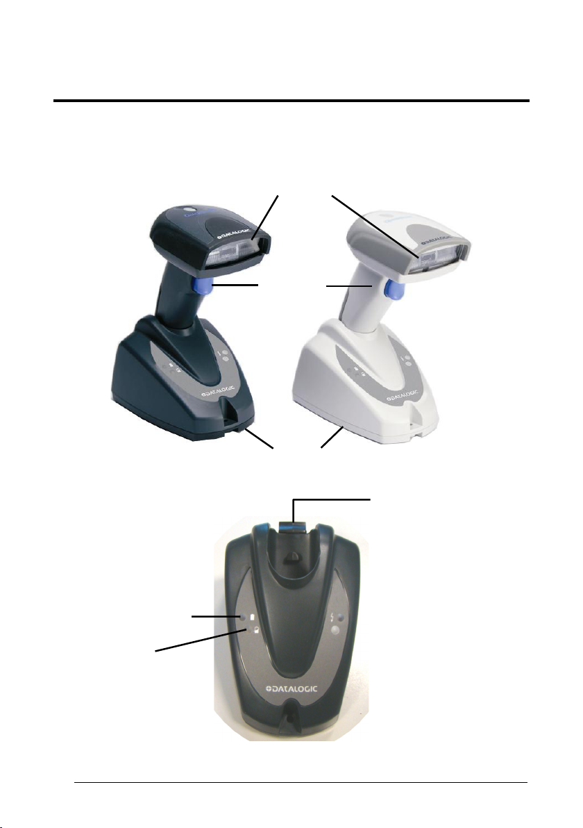
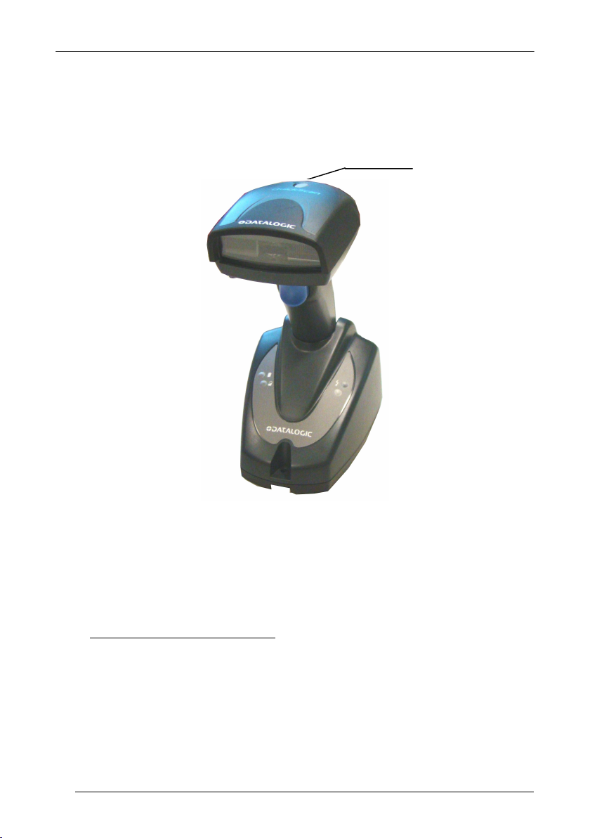
GENERAL VIEW
QUICKSCAN
®
MOBILE READERS
Reading Window
Trigger
Charge completed
(yellow LED)
Charging
(red LED)
vi
Cradle
Locking System Latch
Page 7
INTRODUCTION
1 INTRODUCTION
The QuickScan
handheld device without compromise in performance.
The extensive range of models and options of this family can easily meet any specific
challenges required by retail, and commercial data collections applications.
The QuickScan
where continuous and multi-tasking activities are keys to optimum productivity, lower
cost of ownership and profitable business.
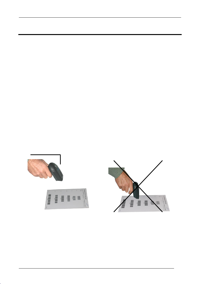
1.1 READING ANGLE
QuickScan
and pull the trigger. Code scanning is performed along the center of the light bar
emitted from the reading window. This bar must cover the entire code.
Successful scanning is obtained by tilting the reader with respect to the barcode to
avoid direct reflections, which could impair the reading performance. See the figures
below.
Successful reading is obtained by an audible tone.
Good read LED
OK Not Advised
®
family provides a valuable solution for users seeking an affordable
®
Mobile is the ideal solution for retail and commercial environments
®
Mobile readers automatically scan barcodes at a distance. Simply aim
1
Page 8
QUICKSCAN® MOBILE
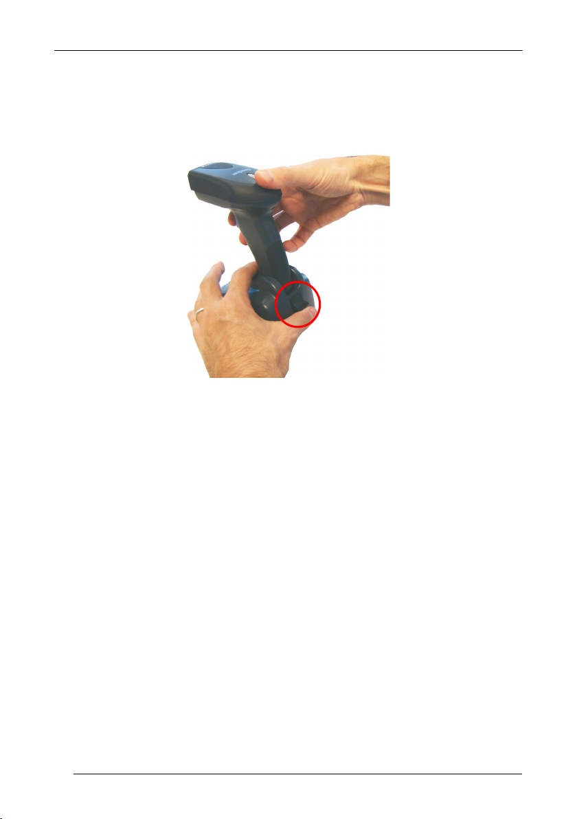
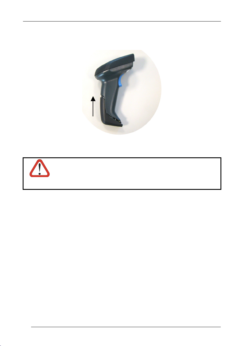
1.2 HANDS-FREE USE
When using the QuickScan
pushing up the locking system as indicated in the following figure.
®
Mobile on the cradle, remember to lock the reader by
2
Page 9
INSTALLATION
2 INSTALLATION
2.1 USING YOUR QUICKSCAN® MOBILE READING SYSTEM
Follow the procedure below to start using your QuickScan
1. Connect a QuickScan
2. Insert the QuickScan
®
Mobile cradle to the Host.
®
Mobile reader into the cradle to start the battery charging.
A full charge of the Lithium battery takes 3.5 – 6 hours.
To achieve the best battery life, it is recommended to perform a full
battery charge before using the reader in hand-held mode.
NOTE
In hands-free use, you can immediately start using the reader, since it is
powered by the cradle.
3. Configure the QuickScan
4. Configure the QuickScan
®
Mobile reader.
®
Mobile cradle.
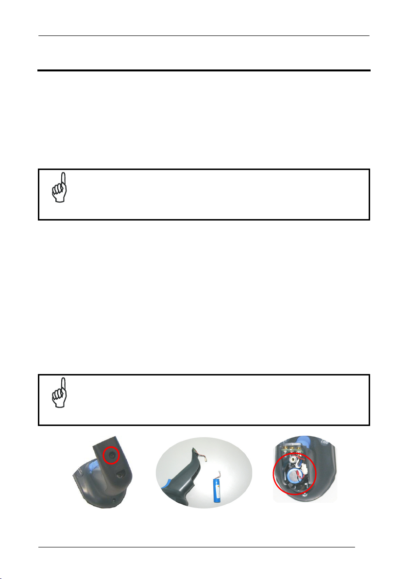
2.2 CHANGING THE BATTERIES
To change the battery of your reader, you must:
1. Unscrew the battery cover screw (Figure 1).
2. Unplug the white connector and remove the old battery (Figure 2).
3. Insert the new battery and plug in the white connector.
®
Mobile reading system:
NOTE
When inserting the new battery into the handle pay attention
position the battery and the connector just as shown in Figure 3.
Figure 1 Figure 2 Figure 3
to
3
Page 10
QUICKSCAN® MOBILE
4. Insert the cover in the handle and screw it back into place.
WARNING
Figure 4
Do not incinerate, disassemble, short terminals or expose to
high temperature. Risk of fire, explosion. Use specified
charger only. Risk of explosion if the battery is replaced by
an incorrect type. Dispose of the batteries as required by the
relevant laws in force.
4
Page 11
INSTALLATION
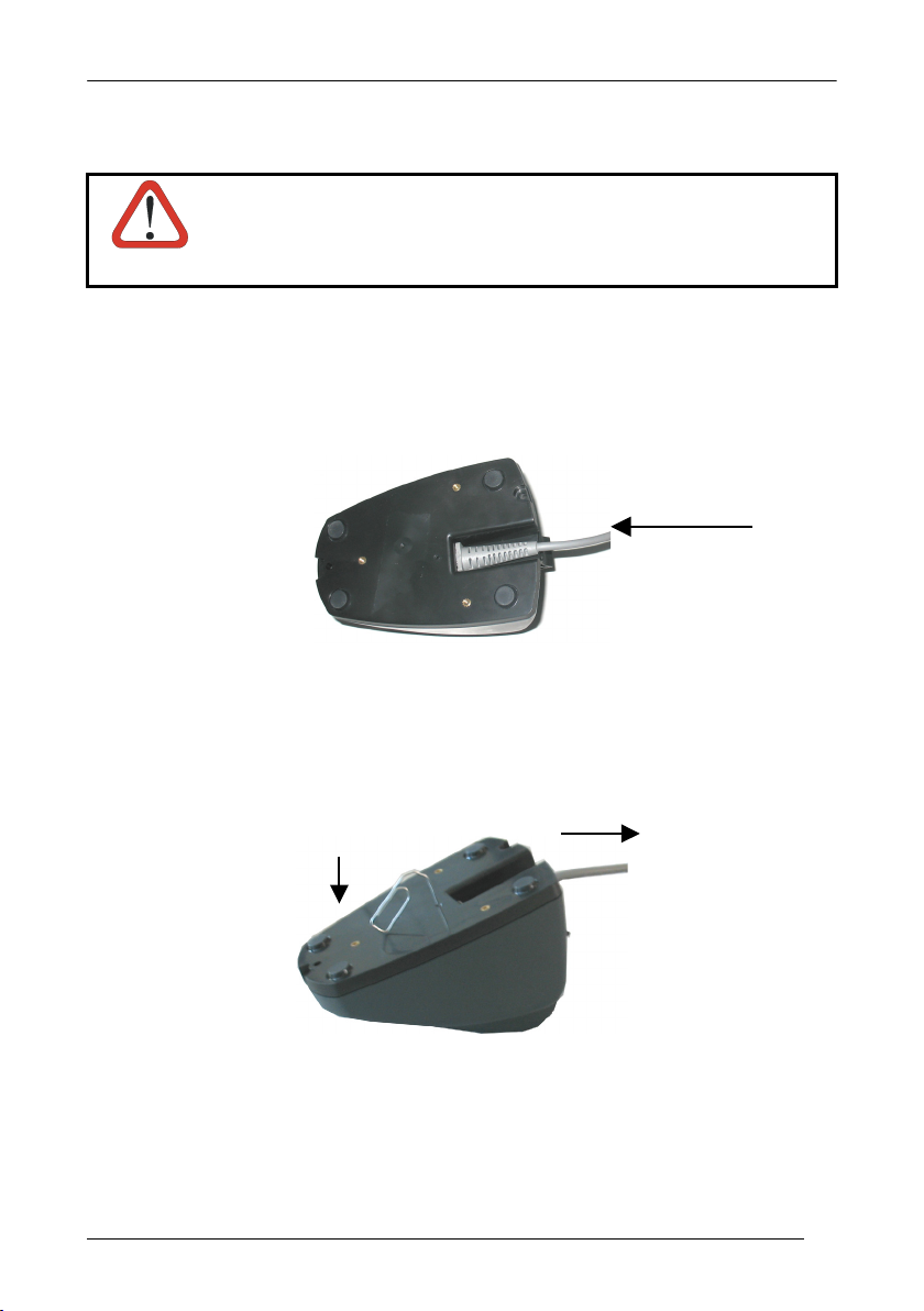
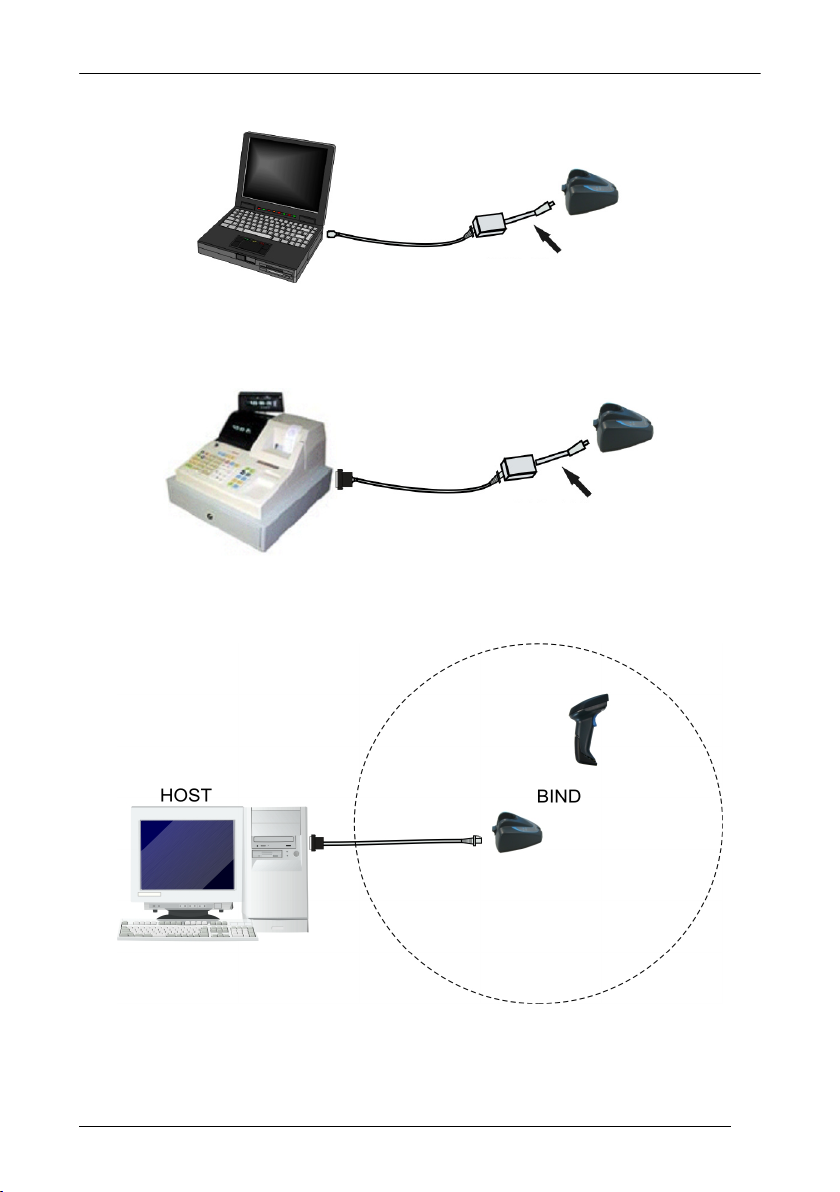
2.3 SYSTEM CONNECTIONS
Connections should always be made with power OFF!
CAUTION
You can connect the QuickScan
connector, using the cable corresponding to the desired interface type.
. Connect the appropriate interface cable to the cradle by simply plugging it into
1
the Host connector on the base of the cradle.
QuickScan® Mobile Cradle - Bottom View
To disconnect the cable, insert a paper clip or other
orresponding to the connector on the base of the cradle. Push down on the clip
c
hile unplugging the cable. Refer to the following figure:
w
®
Mobile cradle to the Host through the dedicated
Interface Cable
similar object into the hole
Disconnecting the Cable
5
Page 12
QUICKSCAN® MOBILE
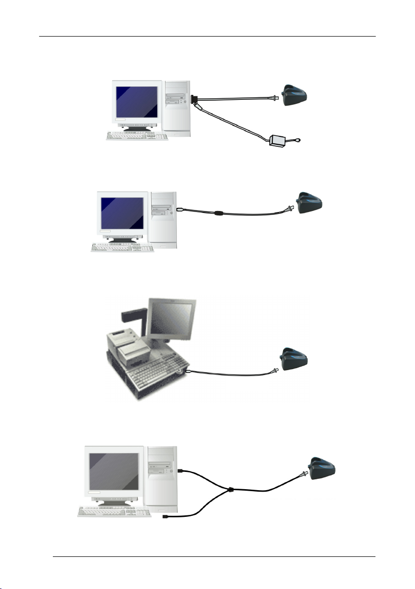
2.4 RS-232 CONNECTION
2.5 USB
2.6 IBM USB POS
2.7 WEDGE CONNECTION
CAB-413
6
CAB-391 or CAB-321 + B-431 CA
Page 13
POWER SUPPLY ADAPTER
2.8 PEN EMULATION CONNECTION
POWER SUPPLY ADAPTER
2.9 SINGLE READER LAYOUT
INSTALLATION
CAB-431
CAB-431
7
Page 14

QUICKSCAN® MOBILE
3 CONFIGURATION
3.1 CONFIGURATION METHODS
3.1.1 Reading Configuration Barcodes
This manual can be used for complete setup and configuration of your reader by
following the setup procedures in this chapter (see par. Error! Reference source not
found. for an overview).
If you wish to change the default settings, this manual provides complete
configuration of your reader in an easy way.
To configure your reader:
1. Open the folded page in Appendix C
during the device configuration.
2. Read the Enter Configuration code ONCE
configuration.
3. Modify the desired parameters in one or more sections following the procedures
given for each group.
4. Read the Exit and Save Configuration code ONCE
page of configuration.
Reference notes describing the operation of the more complex parameters are given
in chapter 4.
3.1.2 Datalogic Aladdin™
Datalogic Aladdin™ is a multi-platform utility program that allows device configuration
using a PC. It provides RS-232 interface configuration as well as configuration
barcode printing.
3.1.3 Copy Command
A previously configured device (Master), can be used to send its configuration directly to
other devices of the same type (Slaves). The particular procedure for each device is
given in par. Error! Reference source not found..
with the hex-numeric table and keep it open
, available at the top of each page of
, available at the top of each
8
Page 15

CONFIGURATION
3.1.4 Sending Configuration Strings from Host
An alternative configuration method is provided in Appendix A using the RS-232 or
USB-COM interface. This method is particularly useful when many devices need to
be configured with the same settings. Batch files containing the desired parameter
settings can be prepared to configure devices quickly and easily.
3.2 QUICKSCAN® MOBILE STAND ALONE SETUP
Read the restore default parameters code below.
1.
Restore QuickScan® Mobile Default
Ì$+$*oÎ
Read the codes below to set the radio address of the QuickScan® Mobile
2.
reader.
Enter configuration
Ì$+;Î
3.
Set Radio Address
ÌRA0RFHÎ
+
4.
four digits for the QuickScan® Mobile Address (from 0000 to 1999).
All readers used in the same area must have different addresses.
Exit and Save configuration
Ì$-?Î
Read the Bind code to pair the QuickScan® Mobile to the cradle.
5.
The reader is dedicated to the cradle. Any previously bound reader will be
excluded.
The yellow LED on the QuickScan
positioned onto the cradle.
Ì$+RN0$-IÎ
Bind
®
Mobile will blink; the reader is ready to be
9
Page 16
QUICKSCAN® MOBILE
Firmly position the reader onto the cradle within 10 seconds, a beep will be
6.
emitted, signaling that the cradle has been paired to the QuickScan
and the yellow LED on the reader will go off.
Yellow LED
®
Mobile,
Read the cradle restore default code:
7.
Go to par. 3.3 Interface Selection.
10
Restore cradle default
Ì$+RX0$-qÎ
Page 17

3.3 INTERFACE SELECTION
Read the interface selection code for your application.
RS-232
Standard
Ì$+CP0$-$Î
POS Terminals
Nixdorf Mode A
Ì$+CM2EC0$->Î
Fujitsu
Ì$+CM1$-ÈÎ
ICL Mode
CONFIGURATION
Ì$+CM0$-ÃÎ
For POS terminal default settings refer to par. 4.9.
PEN
Ì$+CP6$-BÎ
11
Page 18

QUICKSCAN® MOBILE
WEDGE
IBM AT or PS/2 PCs
Ì$+CP500$-aÎ
IBM XT
Ì$+CP503$-vÎ
PC Notebook
Ì$+CP505$-ÈÎ
IBM SURE1
Ì$+CP506$-$Î
IBM Terminal 3153
12
Ì$+CP504$-}Î
Page 19

CONFIGURATION
WEDGE (CONTINUED)
IBM Terminals 31xx, 32xx, 34xx, 37xx:
To select the interface for these IBM Terminals, read the correct KEY
TRANSMISSION code. Select the KEYBOARD TYPE if necessary
(default = advanced keyboard).
KEY TRANSMISSION MODE
make-only keyboard
Ì$+CP502$-oÎ
make-break keyboard
Ì$+CP501$-hÎ
KEYBOARD TYPE
advanced keyboard
Ì$+FK1$-ÉÎ
typewriter keyboard
Ì$+FK0$-ÄÎ
13
Page 20

QUICKSCAN® MOBILE
WEDGE (CONTINUED)
ALT MODE
The ALT-mode selection allows barcodes sent to the PC to be interpreted correctly
independently from the Keyboard Nationality used. You do not need to make a
Keyboard Nationality selection.
(default = Num Lock Unchanged). Make sure the Num Lock key on your
keyboard is ON.
IBM AT - ALT mode
Ì$+CP507$-+Î
PC Notebook - ALT mode
Ì$+CP508$-2Î
WYSE TERMINALS
ANSI Keyboard
14
Ì$+CP509$-9Î
PC Keyboard
Ì$+CP510$-gÎ
ASCII Keyboard
Ì$+CP511$-nÎ
VT220 style Keyboard
Ì$+CP514$-ÇÎ
Page 21

CONFIGURATION
WEDGE (CONTINUED)
DIGITAL TERMINALS
VT2xx/VT3xx/VT4xx
Ì$+CP512$-uÎ
IBM 46XX
(IBM Devices only)
PORT 9B
4501 Protocol
Ì$+CP800$-pÎ
(typical)
1520 Protocol
Ì$+CP801$-wÎ
PORT 5B
1520 Protocol
Ì$+CP801$-wÎ
(typical)
4501 Protocol
Ì$+CP800$-pÎ
15
Page 22

QUICKSCAN® MOBILE
Y
3.4 USB READER CONFIGURATION
The USB interface is compatible with:
Windows 98 (and later) IBM POS for Windows
Mac OS 8.0 (and later) 4690 Operating System
USB Start-up
As with all USB devices, upon connection, the Host performs several checks by
communicating with the QuickScan
QuickScan
®
Mobile reader blinks and normal operations are suspended. Two basic
conditions must be met before the QuickScan
correct USB driver must be loaded and sufficient power must be supplied to the
reader.
For all systems, the correct USB driver for the default
USB-KBD interface is included in the Host Operating
System and will either be loaded automatically or will
be suggested by the O.S. and should therefore be
selected from the dialog box (the first time only).
Normally the Host supplies sufficient power to the
reader, the start-up phase ends correctly, the yellow
LED stops blinking.
In rare cases, if the Host does not supply sufficient
power to the reader, a dialog box will appear on the
Host and the reader will be blocked (yellow LED
continues blinking). In this case, disconnect the USB
device cable at the Host
(yellow LED stops blinking);
and then try a different USB port as indicated by the
Operating System message. You can now read
codes.
At this point you can read the USB interface
configuration code according to your application. Load drivers from the O.S. (if
requested). When configuring the USB-COM interface, the relevant files and drivers
must be installed from the USB Device Installation software, which can be
downloaded from the web page http://www.scanning.datalogic.com
The reader is ready to read barcodes. Successive start-ups will automatically
recognize the previously loaded drivers.
®
Mobile. During this phase the yellow LED on the
®
Mobile is ready to read codes, the
First Start-Up
Connect QuickScan®
Mobile to Host
Load drivers
(if requested)
Select desired USB
interface code
(USB-KBD is default)
Load drivers
(if requested)
Read test codes.
Reader is READY
ellow LED blinks
Yellow LED off –
BEEP OK
.
16
Page 23

CONFIGURATION
USB
USB-KBD
Ì$+UA03$-:Î
USB-KBD-ALT-MODE
Ì$+UA04$-@Î
USB-KBD-APPLE
Ì$+UA05$-FÎ
USB-COM*
Ì$+UA02$-4Î
USB-IBM-Table Top
Ì$+UA00$-(Î
USB-IBM-Hand Held
Ì$+UA01$-.Î
* When configuring USB-COM, the relevant files and drivers must be installed from
the USB Device Installation software, which can be downloaded from the web site
http://www.scanning.datalogic.com.
17
Page 24

QUICKSCAN® MOBILE
3.5 CHANGING DEFAULT SETTINGS
Once your reader is setup, you can change the default parameters to meet your
application needs. Refer to the preceding paragraphs for initial configuration in order
to set the default values and select the interface for your application.
In this manual, the configuration parameters are divided into logical groups making it
easy to find the desired function based on its reference group.
The first four groups are for Standard Interface parameter configuration:
RS-232
USB
WEDGE
PEN EMULATION
The following parameter groups are common to all interface applications:
DATA FORMAT parameters regard the messages sent to the Host system for all
interfaces except Pen Emulation.
READING PARAMETERS control various operating modes and indicator status
functioning.
DECODING PARAMETERS maintain correct barcode decoding in certain special
reading conditions.
CODE SELECTION parameters allow configuration of a personalized mix of codes,
code families and their options.
ADVANCED FORMATTING PARAMETERS allow code concatenation and advanced
formatting of messages towards the Host. It cannot be used with Pen Emulation
connections.
RADIO PARAMETERS (Mobile series only) allow configuration of radio control
parameters.
18
Page 25

RS-232 PARAMETERS
BAUD RATE
PARITY
DATA BITS
STOP BITS
HANDSHAKING
ACK/NACK PROTOCOL
FIFO
INTER-CHARACTER DELAY
RX TIMEOUT
SERIAL TRIGGER LOCK
1. Read the Enter Configuration code ONCE, available at the top of each page.
2. Read configuration codes from the desired groups.
= Read the code and follow the procedure given
= Default value
3. Read the Exit and Save Configuration code ONCE, available at the top of
each page.
19
Page 26

Enter Configuration Exit and Save Configuration
Ì$+;Î
Ì$-?Î
RS-232
BAUD RATE
300 baud
ÌCD1XÎ
1200 baud
ÌCD3^Î
4800 baud
ÌCD5dÎ
19200 baud
ÌCD7jÎ
600 baud
ÌCD2[Î
2400 baud
ÌCD4aÎ
9600 baud
ÌCD6gÎ
38400 baud
ÌCD8mÎ
20
Page 27

Enter Configuration Exit and Save Configuration
Ì$+;Î
Ì$-?Î
RS-232
PARITY
none
ÌCC0SÎ
even parity
ÌCC1VÎ
odd parity
ÌCC2YÎ
DATA BITS
7 bits
ÌCA0OÎ
8 bits
ÌCA1RÎ
9 bits
ÌCA2UÎ
21
Page 28

Enter Configuration Exit and Save Configuration
Ì$+;Î
Ì$-?Î
RS-232
STOP BITS
1 stop bit
ÌCB0QÎ
2 stop bits
ÌCB1TÎ
HANDSHAKING
disable
ÌCE0WÎ
hardware (RTS/CTS)
22
ÌCE1ZÎ
software (XON/XOFF)
ÌCE2]Î
RTS always ON
ÌCE3`Î
See par. 4.1.1 for details.
Page 29

Enter Configuration Exit and Save Configuration
Ì$+;Î
Ì$-?Î
RS-232
ACK/NACK PROTOCOL
disable
ÌER0sÎ
enable
ÌER1vÎ
See par. 4.1.2 for details, particularly on implementing this parameter with QuickScan® Mobile.
FIFO
disable
ÌEC0UÎ
enable
ÌEC1XÎ
See par. 4.1.3 for details.
23
Page 30

Enter Configuration Exit and Save Configuration
Ì$+;Î
Ì$-?Î
RS-232
INTER-CHARACTER DELAY
delay between characters transmitted to Host
ÌCK3Î
Read 2 numbers from the table where:
00 = DELAY disabled
01-99 = DELAY from 1 to 99 milliseconds
delay disabled
RX TIMEOUT
timeout control in reception from Host
ÌCL5Î
Read 2 numbers from the table where:
00 = TIMEOUT disabled
01-99 = TIMEOUT from .1 to 9.9 seconds
rx timeout 5 seconds
See par. 4.1.4 for details.
24
Page 31

Enter Configuration Exit and Save Configuration
Ì$+;Î
Ì$-?Î
RS-232
SERIAL TRIGGER LOCK
disabled
ÌCR0qÎ
Read 2 characters from the Hex/Numeric table in the range 00-FE where:
− First Character enables device trigger
− Second Character inhibits device trigger until the first character is received again.
enable and select characters
ÌCR1tÎ
25
Page 32

USB PARAMETERS
USB-COM
Handshaking, Ack/Nack protocol, FIFO, Inter-character delay, Rx
timeout, Serial trigger lock
USB-KBD
Keyboard nationality, FIFO, Inter-character delay, Inter-code
delay, Control character emulation, USB keyboard speed
USB-IBM
No parameter selection required.
1. Read the Enter Configuration code ONCE, available at the top of each page.
2. Read configuration codes from the desired groups.
= Read the code and follow the procedure given
= Default value
3. Read the Exit and Save Configuration code ONCE, available at the top of
each page.
26
Page 33

Enter Configuration Exit and Save Configuration
Ì$+;Î
Ì$-?Î
USB-COM
HANDSHAKING
disable
ÌCE0WÎ
hardware (RTS/CTS)
ÌCE1ZÎ
software (XON/XOFF)
ÌCE2]Î
RTS always ON
ÌCE3`Î
See par. 4.1.1 for details.
ACK/NACK PROTOCOL
disable
ÌER0sÎ
enable
ÌER1vÎ
See par. 4.1.2 for details.
27
Page 34

Enter Configuration Exit and Save Configuration
Ì$+;Î
Ì$-?Î
USB-COM
FIFO
disable
ÌEC0UÎ
enable
ÌEC1XÎ
delay between characters transmitted to Host
See par. 4.1.3 for details.
INTER-CHARACTER DELAY
28
ÌCK3Î
Read 2 numbers from the table where:
00 = DELAY disabled
01-99 = DELAY from 1 to 99 milliseconds
delay disabled
Page 35

Enter Configuration Exit and Save Configuration
Ì$+;Î
Ì$-?Î
USB-COM
RX TIMEOUT
timeout control in reception from Host
ÌCL5Î
Read 2 numbers from the table where:
00 = TIMEOUT disabled
01-99 = TIMEOUT from .1 to 9.9 seconds
rx timeout 5 seconds
See par. 4.1.4 for details.
SERIAL TRIGGER LOCK
disabled
ÌCR0qÎ
enable and select characters
Read 2 characters from the Hex/Numeric table in the range 00-FE where:
− First Character enables device trigger
− Second Character inhibits device trigger until the first character is received again.
ÌCR1tÎ
29
Page 36

Enter Configuration Exit and Save Configuration
Ì$+;Î
Ì$-?Î
USB-KBD
KEYBOARD NATIONALITY
This parameter default value is restored through the Interface Selection code and not Restore
Default.
Belgian
ÌFJ7yÎ
French
ÌFJ2jÎ
Italian
ÌFJ1gÎ
Spanish
ÌFJ6vÎ
USA
ÌFJ0dÎ
Not Available for USB-KBD-ALT-MODE Interface
English
ÌFJ4pÎ
German
ÌFJ3mÎ
Japanese
ÌFJ8|Î
Swedish
ÌFJ5sÎ
30
Page 37

Enter Configuration Exit and Save Configuration
Ì$+;Î
Ì$-?Î
USB-KBD
FIFO
disable
ÌEC0UÎ
enable
ÌEC1XÎ
delay between characters transmitted to Host
See par. 4.1.3 for details.
INTER-CHARACTER DELAY
ÌCK3Î
Read 2 numbers from the table where:
00 = DELAY disabled
01-99 = DELAY from 1 to 99 milliseconds
delay disabled
31
Page 38

Enter Configuration Exit and Save Configuration
Ì$+;Î
Ì$-?Î
USB-KBD
INTER-CODE DELAY
delay between codes transmitted to Host
ÌFG.Î
Read 2 numbers from the table where:
00 = DELAY disabled
01-99 = DELAY from 1 to 99 seconds
delay disabled
CONTROL CHARACTER EMULATION
CTRL + Shift + Key
32
ÌFO0nÎ
CTRL + Key
ÌFO1qÎ
Page 39

Enter Configuration Exit and Save Configuration
Ì$+;Î
Ì$-?Î
USB-KBD
USB KEYBOARD SPEED
Normal
ÌUT10cÎ
Fast
ÌUT01dÎ
33
Page 40

WEDGE PARAMETERS
KEYBOARD NATIONALITY
CAPS LOCK
CAPS LOCK
A
UTO-RECOGNITION
NUM LOCK
INTER-CHARACTER DELAY
INTER-CODE DELAY
KEYBOARD SETTING
CONTROL CHARACTER
EMULATION
1. Read the Enter Configuration code ONCE, available at the top of each page.
2. Read configuration codes from the desired groups.
= Read the code and follow the procedure given
= Default value
3. Read the Exit and Save Configuration code ONCE, available at the top of
each page.
.
34
Page 41

Enter Configuration Exit and Save Configuration
Ì$+;Î
Ì$-?Î
WEDGE
KEYBOARD NATIONALITY
Belgian
ÌFJ7yÎ
French
ÌFJ2jÎ
Italian
ÌFJ1gÎ
Swedish
ÌFJ5sÎ
English
ÌFJ4pÎ
German
ÌFJ3mÎ
Spanish
ÌFJ6vÎ
USA
ÌFJ0dÎ
The Japanese Keyboard Nationality selection is valid only for IBM AT compatible PCs.
Japanese
ÌFJ8|Î
35
Page 42

Enter Configuration Exit and Save Configuration
Ì$+;Î
Ì$-?Î
WEDGE
CAPS LOCK
caps lock OFF
ÌFE0ZÎ
caps lock ON
ÌFE1]Î
Select the appropriate code to match your keyboard caps lock status.
Note: Caps lock manual configuration is ignored when Caps Lock Auto-Recognition is
enabled.
For PC Notebook interface selections, the caps lock status is automatically recognized;
therefore this command is not necessary.
CAPS LOCK AUTO-RECOGNITION (IBM AT COMPATIBLE ONLY)
disable
36
ÌFP0pÎ
enable
ÌFP1sÎ
Page 43

Enter Configuration Exit and Save Configuration
Ì$+;Î
Ì$-?Î
WEDGE
NUM LOCK
toggle num lock
ÌFL1kÎ
num lock unchanged
ÌFL0hÎ
This selection is used together with the Alt Mode interface selection for AT or Notebook PCs.
It changes the way the Alt Mode procedure is executed; therefore it should be set as follows:
• if your keyboard Num Lock is normally on
• if your keyboard Num Lock is normally off
In this way the device will execute the Alt Mode procedure correctly for your application.
INTER-CHARACTER DELAY
delay between characters transmitted to Host
use num lock unchanged
use toggle num lock
ÌCK3Î
Read 2 numbers from the table where:
00 = DELAY disabled
01-99 = DELAY from 1 to 99 milliseconds
delay disabled
37
Page 44

Enter Configuration Exit and Save Configuration
Ì$+;Î
Ì$-?Î
WEDGE
INTER-CODE DELAY
delay between codes transmitted to Host
ÌFG.Î
Read 2 numbers from the table where:
00 = DELAY disabled
01-99 = DELAY from 1 to 99 seconds
delay disabled
38
Page 45

Enter Configuration Exit and Save Configuration
Ì$+;Î
Ì$-?Î
WEDGE
KEYBOARD SETTING
ALPHANUMERIC KEYBOARD SETTING
The reader can be used with terminals or PCs with various keyboard types and nationalities
through a simple keyboard setting procedure.
The type of computer or terminal must be selected before activating the keyboard setting
command.
Keyboard setting consists of communicating to the reader how to send data corresponding to
the keyboard used in the application. The keys must be set in a specific order.
Press and release a key to set it.
Some characters may require more than one key pressed simultaneously during normal use
(refer to the manual of your PC or terminal for keyboard use). The exact sequence must be
indicated to the reader in this case pressing and releasing the different keys.
Example:
If one has to press the "Shift" and "4" keys simultaneously on the keyboard to transmit the
character "$" to the video, to set the "$", press and release "Shift" then press and release "4".
Each pressed and released key must generate an acoustic signal on the reader, otherwise
repress the key. Never press more than one key at the same time, even if this corresponds to
the normal use of your keyboard.
Press "Backspace" to correct a wrong key entry. In this case the reader emits 2 beeps.
Note: "CAPS LOCK" and "NUM LOCK" must be off before starting the keyboard setting
procedure. "SHIFT" must be repressed for each character and cannot be substituted by
"CAPS LOCK".
setting the alphanumeric keyboard
Read the code above.
Press the keys shown in the following table according to their numerical order.
Some ASCII characters may be missing as this depends on the type of keyboard: these are
generally particular characters relative to the various national symbologies. In this case:
• The first 4 characters (Shift, Alt, Ctrl, and Backspace) can only be substituted with
• characters can be substituted with other single symbols (e.g. "SPACE") even if not
• characters can be substituted with others corresponding to your keyboard.
The reader signals the end of the procedure with 2 beeps indicating the keys have
been registered.
keys not used, or substituted with each other.
included in the barcode set used.
ÌFB0TÎ
39
Page 46

Enter Configuration Exit and Save Configuration
Ì$+;Î
Ì$-?Î
WEDGE
01 : Shift
02 : Alt
03 : Ctrl
04 : Backspace
05 : SPACE 28 : 7 51 : N
06 : ! 29 : 8 52 : O
07 : " 30 : 9 53 : P
08 : # 31 : : 54 : Q
09 : $ 32 : ; 55 : R
10 : % 33 : < 56 : S
11 : & 34 : = 57 : T
12 : ' 35 : > 58 : U
13 : ( 36 : ? 59 : V
14 : ) 37 : @ 60 : W
15 : * 38 : A 61 : X
16 : + 39 : B 62 : Y
17 : , 40 : C 63 : Z
18 : - 41 : D 64 : [
19 : . 42 : E 65 : \
20 : / 43 : F 66 : ]
21 : 0 44 : G 67 : ^
22 : 1 45 : H 68 : _ (underscore)
23 : 2 46 : I 69 : `
24 : 3 47 : J 70 : {
25 : 4 48 : K 71 : |
26 : 5 49 : L 72 : }
27 : 6 50 : M 73 : ~
The keyboard setup functioning is signaled by the LEDs on the cradle. Each key stroke
corresponds to a double blinking of the yellow LED.
By pressing the Backspace key the red LED on the cradle blinks, while the yellow LED stays on.
74 : DEL
CAUTION
Once the procedure has been completed, the yellow LED turns off.
40
Do not place the reader onto the cradle during this procedure. Otherwise,
the battery charging will occur modifying the LEDs functioning.
Page 47

Enter Configuration Exit and Save Configuration
Ì$+;Î
Ì$-?Î
WEDGE
CONTROL CHARACTER EMULATION
CTRL + Shift + Key
ÌFO0nÎ
CTRL + Key
ÌFO1qÎ
41
Page 48

PEN EMULATION
OPERATING MODE
MINIMUM OUTPUT PULSE
CONVERSION TO CODE 39
OVERFLOW
OUTPUT LEVEL
IDLE LEVEL
INTER-BLOCK DELAY
1. Read the Enter Configuration code ONCE, available at the top of each page.
2. Read configuration codes from the desired groups.
= Default value
3. Read the Exit and Save Configuration code ONCE, available at the top of
each page.
42
Page 49

The operating mode parameters are complete commands and do not require reading the
Enter and Exit configuration codes.
PEN EMULATION
OPERATING MODE
interpret mode
Ì$]8Î
Interprets commands without sending them to the decoder.
transparent mode
Ì$[4Î
Sends commands to the decoder without interpreting them.
43
Page 50

Enter Configuration Exit and Save Configuration
Ì$+;Î
Ì$-?Î
200 µs
ÌDG0\Î
600 µs
ÌDG2bÎ
1 ms
ÌDG4hÎ
PEN EMULATION
MINIMUM OUTPUT PULSE
high resolution code
emulation
low resolution code
emulation
See par. 4.2.1 for details.
400 µs
ÌDG1_Î
800 µs
ÌDG3eÎ
1.2 ms
ÌDG5kÎ
44
Page 51

Enter Configuration Exit and Save Configuration
Ì$+;Î
Ì$-?Î
PEN EMULATION
CONVERSION TO CODE 39 AND CODE 128
disable conversion to Code 39
ÌDA0PÎ
Transmits codes in their original format.
enable conversion to Code 39
ÌDA1SÎ
Converts codes read into Code 39 format.
enable conversion to Code 128
ÌDA2VÎ
Converts codes read into Code 128 format.
See par. 4.2.2 for details.
45
Page 52

Enter Configuration Exit and Save Configuration
Ì$+;Î
Ì$-?Î
PEN EMULATION
OVERFLOW
narrow
ÌDH0^Î
medium
ÌDH1aÎ
wide
ÌDH2dÎ
See par. 4.2.3 for details.
OUTPUT LEVEL
normal
(white = logic level 0)
46
ÌDD0VÎ
inverted
(white = logic level 1)
ÌDD1YÎ
See par. 4.2.4 for details.
Page 53

Enter Configuration Exit and Save Configuration
Ì$+;Î
Ì$-?Î
PEN EMULATION
IDLE LEVEL
normal
(black level)
ÌDE0XÎ
inverted
(white level)
ÌDE1[Î
delay between character blocks transmitted to Host
See par. 4.2.4 for details.
INTER-BLOCK DELAY
ÌCK3Î
Read 2 numbers from the table where:
00 = DELAY disabled
01-99 = DELAY from .1 to 9.9 seconds
delay disabled
See par. 4.2.5 for details.
47
Page 54

IBM 46XX
IBM DATA FORMATTING
1. Read the Enter Configuration code ONCE, available at the top of each page.
2. Read configuration codes from the desired groups.
= Default value
3. Read the Exit and Save Configuration code ONCE, available at the top of
each page.
48
Page 55

Enter Configuration Exit and Save Configuration
Ì$+;Î
Ì$-?Î
IBM 46xx
IBM DATA FORMATTING
conversion to Code 39
ÌGD0YÎ
IBM Standard
ÌGD1\Î
mixed IBM Standard + Code 39
ÌGD2_Î
See par. 4.3.1 for details.
49
Page 56

DATA FORMAT
NOT FOR PEN INTERFACES
CODE IDENTIFIER
CUSTOM CODE IDENTIFIER
HEADER
TERMINATOR
SPECIAL KEYS
FIELD ADJUSTMENT
FIELD ADJ. CHARACTER
CODE LENGTH TX
CHARACTER REPLACEMENT
ADDRESS STAMPING
ADDRESS DELIMITER
1. Read the Enter Configuration code ONCE, available at the top of each page.
2. Read configuration codes from the desired groups.
= Read the code and follow the procedure given
= Default value
3. Read the Exit and Save Configuration code ONCE, available at the top of
each page.
50
Page 57

DATA FORMAT
CODE IDENTIFIER TABLE
CODE AIM STANDARD DATALOGIC STANDARD Custom
2/5 interleaved ] I y N
2/5 industrial ] X y P
2/5 normal 5 bars ] S y O
2/5 matrix 3 bars ] X y Q
EAN 8 ] E 4 A
EAN 13 ] E 0 B
UPC A ] X y C
UPC E ] X y D
EAN 8 with 2 ADD ON ] E 5 J
EAN 8 with 5 ADD ON ] E 6 K
EAN 13 with 2 ADD ON ] E 1 L
EAN 13 with 5 ADD ON ] E 2 M
UPC A with 2 ADD ON ] X y F
UPC A with 5 ADD ON ] X y G
UPC E with 2 ADD ON ] X y H
UPC E with 5 ADD ON ] X y I
Code 39 ] A y V
Code 39 Full ASCII ] A y W
CODABAR ] F y R
ABC CODABAR ] X y S
Code 128 ] C y T
EAN 128 ] C y k
ISBT 128
Code 93 ] G y U
CIP/39 ] X y Y
CIP/HR ] X y e
Code 32 ] X y X
MSI ] M y Z
Plessey Standard ] P 0 a
Plessey Anker ] P 1 o
Telepen ] X 0 d
Delta IBM ] X 0 c
Code 11 ] H y b
Code 16K ] K 0 p
Code 49 ] T y q
RSS Expanded Linear and Stacked ] e 0 t
RSS Limited ] e 0 v
RSS 14 Linear and Stacked ] e 0 u
] C4 f
51
Page 58

• AIM standard identifiers are not defined for all codes: the X identifier is assigned to the
code for which the standard is not defined. The y value depends on the selected options
(check digit tested or not, check digit tx or not, etc.).
• When customizing the Datalogic Standard code identifiers, 1 or 2 identifier characters can
be defined for each code type. If only 1 identifier character is required, the second
character must be selected as FF (disabled).
• The code identifier can be singly disabled for any code by simply selecting FF as the first
identifier character.
• Write in the Custom character identifiers in the table above for your records.
DATA FORMAT
52
Page 59

Enter Configuration Exit and Save Configuration
Ì$+;Î
Ì$-?Î
DATA FORMAT
CODE IDENTIFIER
disable
ÌEB0SÎ
Datalogic standard
ÌEB1VÎ
AIM standard
ÌEB2YÎ
custom
ÌEB3\Î
53
Page 60

Enter Configuration Exit and Save Configuration
Ì$+;Î
Ì$-?Î
DATA FORMAT
CUSTOM CODE IDENTIFIER
Read the above code.
(Code Identifiers default to Datalogic standard, see table on previous page).
Select the code type from the code table in Appendix
change.
You can define 1 or 2 identifier characters for each code type. If only 1 identifier character is
required, the second character must be selected as FF (disabled). Read the hexadecimal
value corresponding to the character(s) you want to define as identifiers for the code
selected in step : valid characters are in the range 00-FD. For Wedge and USB-KBD
interfaces, it is also possible to read the Special Key(s) on page 57.
Example
: To define Code 39 Code Identifier = @
define custom code identifier(s)
Read
define custom code identifier(s)
ÌEH/Î
ÌEH/Î
+
B for the identifier you want to
Code 39
ÌVWÎ
+
40
+
FF
54
Page 61

Enter Configuration Exit and Save Configuration
Ì$+;Î
Ì$-?Î
DATA FORMAT
HEADER
After selecting one of the desired Header codes, read the character(s) from the HEX table. Valid characters
are in the range 00-FE. For Wedge and USB-KBD interfaces, it is also possible to read the Special Key(s)
on page 57.
Example
For more details see par. 4.4.1.
no header
ÌEA00*Î
two character header
ÌEA022Î
four character header
ÌEA04:Î
six character header
ÌEA06BÎ
eight character header
ÌEA08JÎ
:
four character header
+ 41 + 42 + 43 + 44 = Header ABCD
one character header
ÌEA01.Î
three character header
ÌEA036Î
five character header
ÌEA05>Î
seven character header
ÌEA07FÎ
55
Page 62

Enter Configuration Exit and Save Configuration
Ì$+;Î
Ì$-?Î
DATA FORMAT
TERMINATOR
After selecting one of the desired Header codes, read the character(s) from the HEX table. Valid characters
are in the range 00-FE. For Wedge and USB-KBD interfaces, it is also possible to read the Special Key(s)
on page 57.
Example:
For more details see par. 4.4.1.
no terminator
ÌEA10-Î
two character terminator
ÌEA125Î
four character terminator
ÌEA14=Î
six character terminator
ÌEA16EÎ
eight character terminator
ÌEA18MÎ
two character terminator
one character terminator
+ 0D + 0A = Terminator CR LF
ÌEA111Î
three character terminator
ÌEA139Î
five character terminator
ÌEA15AÎ
seven character terminator
ÌEA17IÎ
56
Page 63

Enter Configuration Exit and Save Configuration
Ì$+;Î
Ì$-?Î
DATA FORMAT
SPECIAL KEYS
Available only for Wedge IBM AT-PS/2 and USB-KBD Interfaces
It is necess
par. 4.4.2.
NOTE
Select one or wing Special Key according to your needs.
more of the follo s
Special Key 1
Ì9CÄÎ
Special Key 3
Ì9EÈÎ
Special Key 5
ary to define each Special Key by following the procedure given in
ÌA0bÎ
Special Key 2
Ì9DÆÎ
Special Key 4
Ì9FÊÎ
57
Page 64

Enter Configuration Exit and Save Configuration
Ì$+;Î
Ì$-?Î
DATA FORMAT
FIELD ADJUSTMENT
disable field adjustment
ÌEF0[Î
Field adjustment allows a number of characters n, to be added to or subtracted from the
barcode read. The adjustment can be different for each enabled code type. To define
adjustment:
Read the enable field adjustment code:
Select the code type from the Code Identifier Table in Appendix B.
Select the type of adjustment to perform:
right addition
Ì01Î
right deletion
Ì23Î
Read a number in the range 01 - 32 from the Hex/Numeric Table to define how many
characters to add or delete:
Conditions:
• Adjustment is only performed on the barcode data; the Code Identifier and Code Length
Transmission fields are not modified by the field adjustment parameter.
• If the field setting would subtract more characters than exist in the barcode, the subtraction
will take place only to code length 0.
• You can set up to a maximum of 10 different field adjustments on the same barcode family
or on different barcode families.
Example:
To add 4 characters to the right of Standard Code 39 Codes:
Read
enable field adjustment
ÌEF+Î
enable field adjustment
ÌEF+Î
+
Code 39
ÌVWÎ
+
left addition
Ì12Î
left deletion
Ì34Î
right addition
Ì01Î
the field
+
04
58
Page 65

Enter Configuration Exit and Save Configuration
Ì$+;Î
Ì$-?Î
DATA FORMAT
FIELD ADJUSTMENT CHARACTER
Read the field adjustment character code:
Read the hexadecimal value corresponding to the character you want to use for field
adjustment. Valid characters are in the range 00-FE. For Wedge and USB-KBD interfaces, it
is also possible to read the Special Key(s) on page 57.
Example:
To define the field adjustment character = A:
field adjustment character
ÌEG-Î
field adjustment character
Read
+ 41
CODE LENGTH TX
code length not transmitted
The code length is transmitted in the message after the Headers and Code Identifier characters.
The code length is calculated after performing any field adjustment operations.
ÌEE0YÎ
code length transmitted in variable-digit format
ÌEE1\Î
code length transmitted in fixed 4-digit format
ÌEE2_Î
59
Page 66

Enter Configuration Exit and Save Configuration
Ì$+;Î
Ì$-?Î
DATA FORMAT
CHARACTER REPLACEMENT
disable character replacement
ÌEO0mÎ
This parameter allows up to three characters to be replaced from the barcode read. These
substitutions are stored in memory. To define each
Read one of the following character replacement codes:
first character replacement
second character replacement
third character replacement
From the Code Identifier Table in Appendix B, read the Code Identifier for the desired
code family.
0 = character replacement will be effective for all code families.
From the Hex/Numeric Table read two characters corresponding to the Hex value (00-FE)
which identifies the character to be replaced.
also possible to read the Special Key(s) on page 57.
From the Hex/Numeric Table read two characters corresponding to the Hex value (00-FE)
which identifies the new character to replace. For Wedge and USB-KBD interfaces, it is
also possible to read the Special Key(s) on page 57.
FF = the character to be replaced will be substituted with no character, that is, it will be
removed from the code.
ÌEO1pÎ
ÌEO2sÎ
ÌEO3vÎ
character replacement:
For Wedge and USB-KBD interfaces, it is
60
Page 67

Enter Configuration Exit and Save Configuration
Ì$+;Î
Ì$-?Î
DATA FORMAT
Example
The following strings define:
1. First Character Replacement: substitution in Code 39 barcodes of all occurrences of the
2. Second Character Replacement: substitution in Code 39 barcodes of all occurrences of
For Code 39 codes containing the string "0123", the contents transmitted will be "1123".
For Code 39 codes containing the string "ABCD", the contents transmitted will be "BBCD".
:
0 character with the 1 character.
the A character with the B character.
first character replacement
ÌEO1pÎ
second character
replacement
ÌEO2sÎ
Code 39
+
ÌVWÎ
Code 39
+
ÌVWÎ
ASCII characters corresponding
to the HEX value for character 0
+
ASCII characters corresponding
to the HEX value for character A
+
30
41
ASCII characters corresponding
to the HEX value for character 1
+
ASCII characters corresponding
to the HEX value for character B
+
31
42
61
Page 68

ADDRESS STAMPING
disable reader address stamping
ÌRU0ÊÎ
enable reader address stamping
ÌRU1"Î
See par. 4.4.3 for details.
ADDRESS DELIMITER
disable reader address delimiter
ÌRV0!Î
enable reader address delimiter and select characters
62
ÌRV1$Î
Read 2 HEX characters in the range 00-FE.
See par. 4.4.4 for details.
Page 69

READING PARAMETERS
HAND-HELD OPERATION
STAND OPERATION
HARDWARE TRIGGER MODE
TRIGGER-OFF TIMEOUT
FLASH MODE
READS PER CYCLE
SAFETY TIME
BEEPER INTENSITY
BEEPER TONE
BEEPER TYPE
BEEPER LENGTH
STAND RECOGNITION BEEP
1. Read the Enter Configuration code ONCE, available at the top of each page.
2. Read configuration codes from the desired groups.
= Read the code and follow the procedure given
= Default value
3. Read the Exit and Save Configuration code ONCE, available at the top of
each page.
63
Page 70

Enter Configuration Exit and Save Configuration
Ì$+;Î
Ì$-?Î
READING PARAMETERS
HAND-HELD OPERATION
hardware trigger
ÌBK1eÎ
* always on
ÌBK3kÎ
* not available for Mobile series readers
hardware trigger ready
ÌBK4nÎ
STAND OPERATION
ONLY Devices with Stand Recognition Beep
hardware trigger
ÌBU3ÃÎ
* always on
ÌBU2|Î
* not available for Mobile series readers
software trigger
ÌBK0bÎ
automatic
ÌBK2hÎ
software trigger
ÌBU1yÎ
automatic
ÌBU0vÎ
64
Page 71

Enter Configuration Exit and Save Configuration
Ì$+;Î
Ì$-?Î
trigger active level
ÌBA0NÎ
READING PARAMETERS
HARDWARE TRIGGER MODE
See par. 4.5.1 for details
trigger active pulse
ÌBA1QÎ
TRIGGER-OFF TIMEOUT
trigger-off timeout
ÌBD$Î
Read 2 numbers in the range 00-99:
00 = disables the trigger-off timeout
01-99 = corresponds to a max. 99-sec. delay after the trigger
trigger-off timeout disabled
press to allow the reader to turn off automatically.
See par. 4.5.2 for details.
65
Page 72

Enter Configuration Exit and Save Configuration
Ì$+;Î
Ì$-?Î
READING PARAMETERS
FLASH MODE
"FLASH" ON duration
ÌBB0PÎ
"FLASH" OFF duration
ÌBB1SÎ
Read 2 numbers in the range 01-99:
01 to 99 = from .1 to 9.9 seconds.
Flash-ON = 1 sec. Flash-OFF = 0.6 sec
READS PER CYCLE
one read per cycle
66
ÌBC0RÎ
multiple reads per cycle
ÌBC1UÎ
See par. 4.5.3 for details.
Page 73

Enter Configuration Exit and Save Configuration
Ì$+;Î
Ì$-?Î
READING PARAMETERS
SAFETY TIME
Limits same
Read 2 numbers in the range 00-99:
00 = no same code consecutive reading until reader is
01-99 = timeout from .1 to 9.9 seconds before a consecutive read
safety time = 0.5 sec
safety time
ÌBE&Î
code consecutive reading.
removed (no decoding) for at least 400 ms.
on same code.
See par. 4.5.4 for details.
BEEPER INTENSITY
* very low intensity
ÌBG0ZÎ
medium intensity
ÌBG2`Î
* This sets the beeper OFF for data entry, while for all other beeper signals it has the
meaning “very low intensity”. The Beeper Intensity parameter is effective for all operating
conditions described in par. 5.2.
low intensity
ÌBG1]Î
high intensity
ÌBG3cÎ
67
Page 74

Enter Configuration Exit and Save Configuration
Ì$+;Î
Ì$-?Î
tone 1
ÌBH0\Î
tone 3
ÌBH2bÎ
monotone
ÌBJ0`Î
ÌBI0^Î
long
READING PARAMETERS
BEEPER TONE
ÌBH1_Î
ÌBH3eÎ
tone 2
tone 4
BEEPER TYPE
ÌBJ1cÎ
bitonal
BEEPER LENGTH
ÌBI1aÎ
short
68
Page 75

Enter Configuration Exit and Save Configuration
Ì$+;Î
Ì$-?Î
disable
ÌBV0xÎ
READING PARAMETERS
STAND RECOGNITION BEEP
ONLY Devices with Stand Recognition
ÌBV1{Î
enable
69
Page 76

DECODING PARAMETERS
INK SPREAD
OVERFLOW CONTROL
INTERDIGIT CONTROL
DECODING SAFETY
PUZZLE SOLVER™
Before ch
par. 4.6.
CAUTION
1. Read the Enter Configuration code ONCE, available at t
anging these parameter values read the descriptions in
he top of each page.
2. Read configuration codes from the desired groups.
. Read the Exit and Save Configuration code ONCE
3 , available at the top of
each page.
= Default value
70
Page 77

Enter Configuration Exit and Save Configuration
Ì$+;Î
Ì$-?Î
DECODING PARAMETERS
INK SPREAD
disable
ÌAX0{Î
enable
ÌAX1~Î
See par. 4.6.1 for details.
OVERFLOW CONTROL
disable
ÌAW1|Î
enable
ÌAW0yÎ
See par. 4.6.2 for details.
71
Page 78

Enter Configuration Exit and Save Configuration
Ì$+;Î
Ì$-?Î
one read
ÌED0WÎ
(decoding safety disabled)
three reads
ÌED2]Î
Required number of good reads before accepting code.
DECODING PARAMETERS
INTERDIGIT CONTROL
disable
ÌAV0wÎ
enable
ÌAV1zÎ
See par. 4.6.3 for details.
DECODING SAFETY
two reads
ÌED1ZÎ
four reads
ÌED3`Î
72
Page 79

Enter Configuration Exit and Save Configuration
Ì$+;Î
Ì$-?Î
DECODING PARAMETERS
PUZZLE SOLVER™
disable
ÌAU0uÎ
enable
ÌAU1xÎ
In the case of damaged or poorly printed codes, this parameter allows reading multiple parts of
the single code to reconstruct it.
To read codes using this technology, simply move the illuminated bar over the code so that
each line of the code is scanned. During this process a series of brief “ticks” indicates that
reading is proceeding correctly.
Conditions:
• This parameter is only valid for the following codes:
EAN 8
without Add-on
Code 128 Code 39
• For Code 39, Check digit control is forced.
• PuzzleSolver™ is not valid for ISBT 128 code.
EAN 13
without Add-on
UPC A
without Add-on
73
Page 80

CODE SELECTION
EAN/UPC FAMILY
2/5 FAMILY
CODE 39 FAMILY
CODE 128 FAMILY
CODABAR FAMILY
CODE 93
MSI
PLESSEY
TELEPEN
DELTA IBM
CODE 11
CODE 16K
CODE 49
GS1 DATABAR™
1. Read the Enter Configuration code ONCE, available at the top of each page.
2. Read configuration codes from the desired groups.
= Read the code and follow the procedure given
= Default value
3. Read the Exit and Save Configuration code ONCE, available at the top of
each page.
74
Page 81

Enter Configuration Exit and Save Configuration
Ì$+;Î
Ì$-?Î
CODE SELECTION
DISABLE ALL CODE FAMILIES
ÌAZ0ÃÎ
The reader allows up to 5 code selections. This does not limit the
NOTE
SINGLE
SELECTIONS =
Example
5 code selections: 1. 2/5 Interleaved
2. 2/5 Industrial
3. Code 128 + EAN 128
4. Code 39 Full ASCII + Code 32
5. UPC A/UPC E
In this section all SINGLE
number of CODES enabled to 5, as it depends on the code family.
• ONE combination code from the EAN family
• ONE code
code selections are underlined and in bold.
from the 2/5 family
75
Page 82

Enter Configuration Exit and Save Configuration
Ì$+;Î
Ì$-?Î
CODE SELECTION
EAN/UPC FAMILY
disable the family
ÌAA0MÎ
Read the desired family code
Note:
Since the EAN/UPC without ADD ON code selection is enabled by default, to correctly enable
another selection, first disable the family.
WITHOUT ADD ON
EAN 8/EAN 13/UPC A/UPC E
ÌAA1PÎ
EAN 8/EAN 13
76
ÌAA3VÎ
UPC A/UPC E
ÌAA4YÎ
Page 83

Enter Configuration Exit and Save Configuration
Ì$+;Î
Ì$-?Î
CODE SELECTION
WITH ADD ON 2 AND 5
EAN 8/EAN 13/UPC A/UPC E
ÌAA5\Î
EAN 8/EAN 13
ÌAA6_Î
EAN 8/EAN 13
ÌAAK7Î
ÌAA7bÎ
WITH ADD ON 2 ONLY
UPC A/UPC E
UPC A/UPC E
ÌAAM=Î
EAN 8/EAN 13
ÌAAL:Î
WITH ADD ON 5 ONLY
UPC A/UPC E
ÌAAN@Î
77
Page 84

Enter Configuration Exit and Save Configuration
Ì$+;Î
Ì$-?Î
CODE SELECTION
WITH AND WITHOUT ADD ON
EAN/UPC with and without ADD ON no
Autodiscrimination
ÌAA8Ad03Î
EAN/UPC Autodiscrimination ADD ON by
Prefix
ÌAA8Ad19Î
By setting the EAN/UPC Autodiscrimination ADD ON by Prefix, the desired prefixes
must be selected by reading the corresponding codes given in the following section,
since no prefix is configured by default.
78
Page 85

Enter Configuration Exit and Save Configuration
Ì$+;Î
Ì$-?Î
CODE SELECTION
SELECT EAN/UPC PREFIXES
When scanning the following codes, barcodes starting with the
selected prefixes will be read and transmitted only if the ADD ON is
present. If no ADD ON is found, the barcode will not be read.
NOTE
Barcodes starting with different characters are read regardless of ADD
ON presence and transmitted always without ADD ON.
Cancel All Selections
ÌET0wÎ
select one or more of the following prefixes:
434/439
ÌET3434ET4439ÉÎ
OR
378/379
ÌET1378ET2379PÎ
ÌET7977QÎ
ÌET8978ZÎ
ÌET9979cÎ
The commands above are not mutually exclusive. They can be used to configure
more than one set of prefixes simultaneously.
977
979
414/419
ÌET5414ET6419}Î
978
79
Page 86

Enter Configuration Exit and Save Configuration
Ì$+;Î
Ì$-?Î
CODE SELECTION
Example
The following string allows reading and transmitting with ADD ON all EAN/UPC starting with the
434/439, 977 and 978 prefixes:
1. EAN/UPC Autodiscrimination ADD ON by Prefix.
2. 434/439: enables reading and transmission with ADD ON of all EAN/UPC barcodes
3. 977: enables reading and transmission with ADD ON of all EAN/UPC barcodes starting
4. 978: enables reading and transmission with ADD ON of all EAN/UPC barcodes starting
To clear the current prefix selections:
1. Cancel all Selections
:
starting with 434/439 prefixes.
with 977 prefix.
with 978 prefix.
EAN/UPC Autodiscrimination ADD ON by
Prefix
ÌAA8Ad19Î
+
ÌET7977QÎ
Cancel All Selections
977 978
434/439
+
ÌET3434ET4439ÉÎ
+
ÌET8978ZÎ
+
80
ÌET0wÎ
Page 87

Enter Configuration Exit and Save Configuration
Ì$+;Î
Ì$-?Î
CODE SELECTION
EAN/UPC CHECK DIGIT TX SELECTIONS
For each code type in this family you can choose to transmit the check digit or not
CHECK DIGIT TRANSMISSION
EAN 8
ÌAAG1oÎ
EAN 13
ÌAAH1rÎ
UPC A
ÌAAI1uÎ
UPC E
ÌAAJ1xÎ
NO CHECK DIGIT
TRANSMISSION
ÌAAG0kÎ
ÌAAH0nÎ
ÌAAI0qÎ
ÌAAJ0tÎ
EAN 8
EAN 13
UPC A
UPC E
81
Page 88

Enter Configuration Exit and Save Configuration
Ì$+;Î
Ì$-?Î
CODE SELECTION
CONVERSION OPTIONS
UPC E to UPC A conversion
ÌAAAÄÎ
UPC E to EAN 13 conversion
ÌAABÇÎ
UPC A to EAN 13 conversion
ÌAACÊÎ
EAN 8 to EAN 13 conversion
ÌAAD"Î
Enable only ISBN conversion
82
ÌAP1nÎ
Enable only ISSN conversion
ÌAP2qÎ
Enable both ISBN and ISSN conversion
ÌAP3tÎ
Disable both ISBN and ISSN conversion
ÌAP0kÎ
Page 89

Enter Configuration Exit and Save Configuration
Ì$+;Î
Ì$-?Î
CODE SELECTION
disable the family
ÌAC0QÎ
Read the desired family code
The pharmaceutical code below is part of
the 2/5 family but has no check digit or
code length selections.
Interleaved 2/5
ÌAC1TÎ
Normal 2/5 (5 Bars)
ÌAC2WÎ
Industrial 2/5 (IATA)
ÌAC3ZÎ
Matrix 2/5 (3 Bars)
ÌAC4]Î
Code CIP/HR
ÌAC5`Î
French pharmaceutical code
2/5 FAMILY
Read a check digit selection
CHECK DIGIT TABLE
no check digit control
Ì12Î
check digit control and transmission
Ì23Î
check digit control without transmission
Ì34Î
Read 4 numbers for the code length
where:
− First 2 digits = minimum code
length.
− Second 2 digits = maximum code
length.
The maximum code length is 99
characters.
The minimum code length must always
be less than or equal to the maximum.
Examples:
0199 = variable from 1 to 99 digits in
the code.
1010 = 10 digit code length only.
83
Page 90

Enter Configuration Exit and Save Configuration
Ì$+;Î
Ì$-?Î
Read the desired family code
Standard Code 39
ÌAB1RÎ
Full ASCII Code 39
ÌAB2UÎ
CODE SELECTION
CODE 39 FAMILY
disables the family
ÌAB0OÎ
Read a check digit selection
CHECK DIGIT TABLE
no check digit control
Ì12Î
check digit control
and transmission
Ì23Î
check digit control
without transmission
Ì34Î
84
Page 91

Enter Configuration Exit and Save Configuration
Ì$+;Î
Ì$-?Î
CODE SELECTION
The pharmaceutical codes below are part of the Code 39 family but have no check digit
selections.
Code CIP39
ÌAB3XÎ
French pharmaceutical code
Code 32
ÌAB4[Î
The code length selection is valid for the entire Code 39 family
Read the code + 4 numbers for the code length where:
First 2 digits = minimum code length.
Second 2 digits = maximum code length.
CODE LENGTH (optional)
Italian pharmaceutical code
set code length
ÌAB*=Î
The maximum code length is 99 characters.
The minimum code length must always be less than or equal to the maximum.
Examples: 0199 = variable from 1 to 99 digits in the code. 1010 = 10 digit code length only.
85
Page 92

Enter Configuration Exit and Save Configuration
Ì$+;Î
Ì$-?Î
CODE SELECTION
CODE 128 FAMILY
disables the family
ÌAI0]Î
Read the desired family code
Code 128
ÌAI11=Î
control without transmission
of check digit
EAN 128
ÌAI21@Î
control without transmission
of check digit
Transmit GS Before Code
Code EAN 128 uses the ASCII <GS> character to separate a variable length code field from the
next code field. This character can also be transmitted before the code.
disable
If the <GS> character has been modified in the Character Replacement parameter, the new
character is affected by this command.
86
ÌEQ0qÎ
enable
ÌEQ1tÎ
Page 93

Enter Configuration Exit and Save Configuration
Ì$+;Î
Ì$-?Î
CODE SELECTION
ISBT 128
ÌAI31CÎ
Enabling ISBT 128 automatically disables Puzzle Solver™.
CODE LENGTH (optional)
The code length selection is valid for the entire Code 128 family.
Read the code + 4 numbers for the code length where:
First 2 digits = minimum code length
Second 2 digits = maximum code length
The maximum code length is 99 characters. The minimum code length must always be less
than or equal to the maximum.
Examples: 0199 = variable from 1 to 99 digits in the code. 1010= 10 digit code length only.
The length is calculated on the output string.
CODE 93
disables the code
set code length
ÌAILJÎ
ÌAK0aÎ
Code 93
ÌAK1dÎ
control without transmission
of check digit
87
Page 94

Enter Configuration Exit and Save Configuration
Ì$+;Î
Ì$-?Î
CODE SELECTION
CODABAR FAMILY
disable the family
ÌAD0SÎ
Read the desired equality control code
no start/stop character equality control
Standard Codabar
ÌAD113Î
Standard Codabar
ÌAD127Î
start/stop character equality control
Read a start/stop transmission
selection
START/STOP CHARACTER
TRANSMISSION
no transmission
Ì12Î
transmission
Ì23Î
The Codabar ABC code below uses a fixed start/stop character transmission selection.
Codabar ABC
88
ÌAD212)Î
no start/stop character equality control but transmission.
Page 95

Enter Configuration Exit and Save Configuration
Ì$+;Î
Ì$-?Î
CODE SELECTION
Codabar ABC Forced Concatenation
enable Codabar ABC with forced concatenation
ÌAD2321Î
The code length selection is valid for the entire Codabar family
Read the code + 4 numbers for the code length where:
First 2 digits = minimum code length.
Second 2 digits = maximum code length.
The maximum code length is 99 characters.
The minimum code length must always be less than or equal to the maximum.
Examples: 0199 = variable from 1 to 99 digits in the code. 1010 = 10 digit code length only.
The start/stop character case selections below are valid for the entire Codabar family:
non start/stop character equality control but transmission
CODE LENGTH (optional)
set code length
ÌAD*AÎ
START/STOP CHARACTER CASE IN TRANSMISSION
transmit start/stop characters in lower case
ÌADA0_Î
transmit start/stop characters in upper case
ÌADA1cÎ
89
Page 96

Enter Configuration Exit and Save Configuration
Ì$+;Î
Ì$-?Î
CODE SELECTION
MSI
disable the family
ÌAE0UÎ
Enable the code by selecting one of the check digit selections.
no check digit control
ÌAE1XÎ
MOD10 check digit control
check digit transmission
ÌAE3^Î
MOD11 - MOD10 check digit control
check digit transmission
MOD11 - MOD10 check digit control
ÌAE5dÎ
MOD10 - MOD10 check digit control
check digit transmission
MOD10 - MOD10 check digit control
ÌAE7jÎ
MOD10 check digit control
no check digit transmission
ÌAE2[Î
no check digit transmission
ÌAE4aÎ
no check digit transmission
ÌAE6gÎ
90
Page 97

Enter Configuration Exit and Save Configuration
Ì$+;Î
Ì$-?Î
CODE SELECTION
PLESSEY
disable the family
ÌAF0WÎ
Enable the code by selecting one of the check digit selections.
Standard Plessey
no check digit control
ÌAF117Î
check digit control
check digit not transmitted
ÌAF13?Î
check digit control
check digit transmitted
ÌAF22>Î
Anker Plessey
check digit control
check digit transmitted
ÌAF12;Î
no check digit control
ÌAF21:Î
check digit control
check digit not transmitted
ÌAF23BÎ
91
Page 98

Enter Configuration Exit and Save Configuration
Ì$+;Î
Ì$-?Î
CODE SELECTION
TELEPEN
disable the family
ÌAL0cÎ
Enable the code by selecting one of the check digit selections.
Numeric Telepen
no check digit control
ÌAL11CÎ
check digit control
check digit not transmitted
ÌAL13KÎ
Alphanumeric Telepen
check digit control
check digit transmitted
ÌAL22JÎ
check digit control
check digit transmitted
ÌAL12GÎ
no check digit control
ÌAL21FÎ
check digit control
check digit not transmitted
ÌAL23NÎ
92
Page 99

Enter Configuration Exit and Save Configuration
Ì$+;Î
Ì$-?Î
CODE SELECTION
DELTA IBM
disable the family
ÌAH0[Î
Enable the code by selecting one of the check digit selections.
no check digit control
ÌAH1^Î
Type 1 check digit control
ÌAH2aÎ
Type 2 check digit control
ÌAH3dÎ
93
Page 100

Enter Configuration Exit and Save Configuration
Ì$+;Î
Ì$-?Î
CODE SELECTION
CODE 11
disable the family
ÌAG0YÎ
Enable the code by selecting one of the check digit selections.
Type C check digit control
check digit transmitted
ÌAG21<Î
Type K check digit control
check digit transmitted
ÌAG31?Î
Type C and Type K
check digit control
check digits transmitted
ÌAG41BÎ
no check digit control
ÌAG1\Î
Type C check digit control
check digit not transmitted
ÌAG22@Î
Type K check digit control
check digit not transmitted
ÌAG32CÎ
Type C and Type K
check digit control
check digits not transmitted
ÌAG42FÎ
94
 Loading...