

Page 1
Matrix 450™ + LT-03X
QUICK REFERENCE GUIDE
NOTE
This manual illustrates a Stand Alone application. For other types of
installations, such as ID-NET™, and for a complete reader configuration using
the VisiSet™ configuration program, refer to the Matrix 450™ Reference
Manual available on the mini-DVD and also downloadable from the Web at
www.automation.datalogic.com.
821000250
Page 2

MATRIX 450™ QUICK REFERENCE GUIDE
2
UPDATES AVAILABILITY
UK/US
The latest drivers and documentation updates for this product are available on Internet.
Log on to: www.automation.datalogic.com
I
Su Internet sono disponibili le versioni aggiornate di driver e documentazione di questo
prodotto. Collegarsi a: www.automation.datalogic.com
F
Les versions mises à jour de drivers et documentation de ce produit sont disponibles sur
Internet. Cliquez sur : www.automation.datalogic.com
D
Im Internet finden Sie die aktuellsten Versionen der Treiber und Dokumentation von
diesem Produkt. Adresse : www.automation.datalogic.com
E
En Internet están disponibles las versiones actualizadas de los drivers y documentación
de este producto. Dirección Internet : www.automation.datalogic.com
SERVICES AND SUPPORT
Datalogic provides several services as well as technical support through its website. Log on to
www.automation.datalogic.com and click on the links indicated for further information:
PRODUCTS
Search through the links to arrive at your product page which describes specific Info, Features,
Applications, Models, Accessories, and specific Downloads.
DOWNLOAD > PRODUCT LITERATURE > SW&UTILITIES
The VisiSet™
utility program, which allows device configuration using a PC can be downloaded
from this page. It provides RS232 and Ethernet interface configuration.
SERVICE
- Overview
- Technical Support, Maintenance Agreements and Warranty Extensions
- Repair Centers
- Helpdesk
- Material Return Authorization
LEGAL NOTICES
© 2012 Datalogic Automation S.r.l. ALL RIGHTS RESERVED. Protected to the fullest extent under
U.S. and international laws. Copying, or altering of this document is prohibited without express written
consent from Datalogic Automation S.r.l.
Datalogic and the Datalogic logo are registered trademarks of Datalogic S.p.A. in many countries,
including the U.S.A. and the E.U.
Matrix 450, ID-NET, VisiSet and X-PRESS are trademarks of Datalogic Automation S.r.l. All other
brand and product names mentioned herein are for identification purposes only and may be
trademarks or registered trademarks of their respective owners.
Datalogic shall not be liable for technical or editorial errors or omissions contained herein, nor for
incidental or consequential damages resulting from the use of this material.
Page 3

MATRIX 450™ QUICK REFERENCE GUIDE
3
STEP 1 – ASSEMBLE THE READER
The first step to perform is to assemble the accessories that make up the Matrix 450™
reader. The lens and lighting system or external illuminator must be used. This procedure
shows an LT-03x lighting system.
CAUTION
Matrix 450™ must be disconnected from the power supply during this
procedure.
1. In a dust-free environment, remove the Matrix 450™ Lens Cover by unscrewing it.
CAUTION
Do not touch the sensor aperture, lens glass or lens cover glass. These
areas must be kept clean. Avoid any abrasive substances that might
damage these surfaces during cleaning.
2. Remove the sensor protection label by pulling it off of the base.
3. Mount the LNS-12xx lens by slowly screwing it onto the base until it arrives at the
mechanical stop.
NOTE
The lens mount is equipped with a special slip mechanism and together
with the LT-03x design facilitates the focusing procedure during installation,
for example if the locking knobs on the lens are obstructed by the body of
the illuminator. See note in Step 4 "Focusing the Reader" or Step 8.
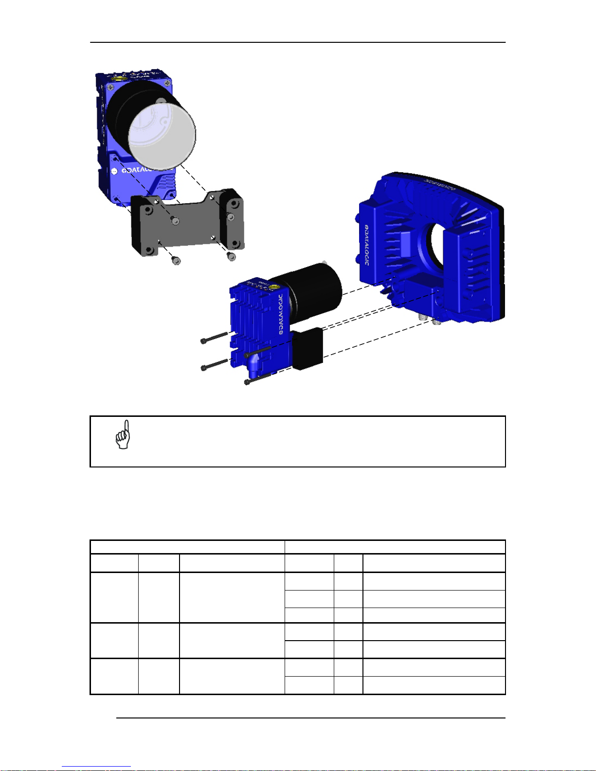
Figure 1 – Assembling Matrix 450™ and LNS-12xx Lens
NOTE
The anti-vibration components are already mounted to all Datalogic
LNS-12xx Lenses.
4. To keep dust and dirt off of the lens during mounting, temporarily replace the lens cover.
Locking Knobs Lens Cover
anti-vibration components
(see note below)
Protective Film
(remove before calibration)
Matrix 450™ Base
Page 4
MATRIX 450™ QUICK REFERENCE GUIDE
4
Figure 2 – Assembling Matrix 450™ to LT-03x
NOTE
The mating bracket can be mounted in the reverse direction to create a
compact version of the Matrix 450™ + LT-03x assembly. The compact
assembly however will reduce access to the lens for the focusing procedure.
REQUIRED ACCESSORIES
The following table shows the correct lens/illuminator combinations to be used for Matrix
450™ imager assembly.
Lenses Illuminators
93ACC0041 LNS-1216
16 mm C-Mount Lens 5MP
with anti-vibration components
93A400034 LT-032 ULTRA POWER LT NARROW BLUE 40°
93A400032 LT-030
ULTRA POWER LT SUPERNARROW
BLUE 20°
93A400033 LT-031
ULTRA POWER LT SUPERNARROW
WHITE 20°
93ACC0034 LNS-1225
25 mm C-Mount Lens 5MP
with anti-vibration components
93A400034 LT-032 ULTRA POWER LT NARROW BLUE 40°
93A400032 LT-030 ULTRA POWER LT SUPERNARROW
BLUE 20°
93ACC0035 LNS-1235
35 mm C-Mount Lens 5MP
with anti-vibration components
93A400033 LT-031 ULTRA POWER LT SUPERNARROW
WHITE 20°
93A400032 LT-030 ULTRA POWER LT SUPERNARROW
BLUE 20°
93ACC0036 LNS-1250
50 mm C-Mount Lens 5MP
with anti-vibration components
93A400033 LT-031 ULTRA POWER LT SUPERNARROW
WHITE 20°
Page 5

MATRIX 450™ QUICK REFERENCE GUIDE
5
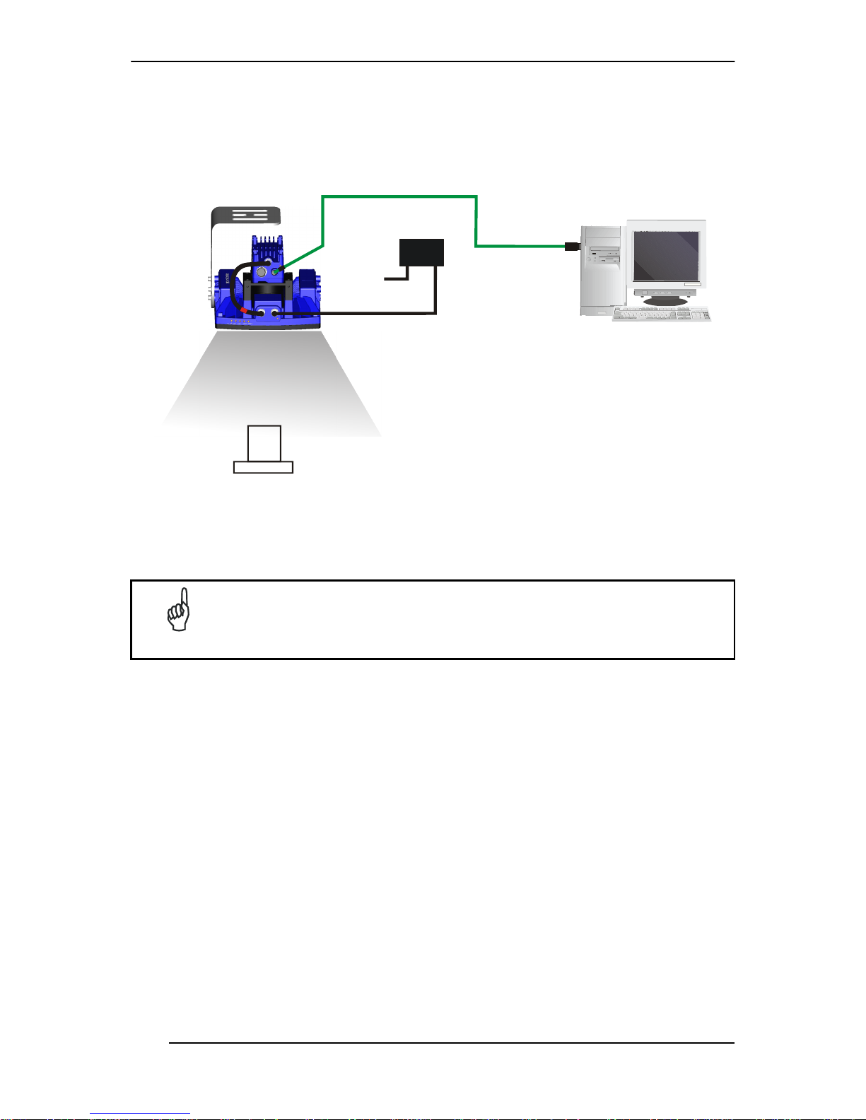
STEP 2 – CONNECT THE SYSTEM
In the typical standalone layout shown in the figure below a serial host is connected to the
Matrix 450™ + LT-03x. The reader operates in One Shot or Phase Mode and can use an
external trigger to signal image acquisition.
The CBX is used to facilitate the connection between the Matrix 450™ + LT-03x assembly
and the serial host interface, external trigger, serial aux configuration, and optional input and
output devices.
Matrix 450™ Standalone Layout to Serial Host
Power Supply Connection
Use the PG-120 power Kit (3 versions for European, UK or US plug) and CAB-PG-0002
+ BA400 connector to connect the PG-120 to the CBX. An alternative power supply to the
PG-120 is the PWR-120.
CBX Connection
Use CAB-LP-0x to supply power from the CBX to the LT-03x. Connect Brown/White
wires to Vdc and Black/Blue wires to GND. Connect the cable shield to Earth ground.
Use CAB-MS0x between Matrix 450™ and the CBX for: power, serial host, external
trigger device (photocell), serial aux, additional I/O connections.
Optionally: use the CAB-GE0x for the Gigabit Ethernet connection towards a remote host
or Datalogic WebSentinel™ monitoring station.
Matrix 450™ LT-03x Connection
Use the CAB-LD-102 (no power) cable (provided with the LT-03x), to connect the
communication signals between the Matrix 450™ and the LT-03x while isolating the
power. Through the CBX internal power switch you can control power to the Matrix 450™
independently from the LT-03x.
NOTE
Matrix 450™ does not support sourcing power towards the CBX in order to
power I/O devices. These devices must be powered through the CBX or
from an external source.
CAB-GE0x (to Remote Host or
Datalogic WebSentinel™ Monitor)
CAB-PG-0002
+ BA400
CAB-MS0x
CAB-LP-0x
CAB-LD-102
(no power)
Serial Host
PG-120
Ext. Trigger
CBX500
AUX (Matrix 450™
configuration)
I/O
Page 6
MATRIX 450™ QUICK REFERENCE GUIDE
6
Alternatively, Matrix 450™ + LT-03x can be connected directly to an Ethernet host through
the Gigabit Ethernet connection (CAB-GE0x). If an external trigger is not necessary, the
layout is simplified. The LT-03x is powered directly from the PG-120 through the CAB-PG0105 cable. The CAB-LD-002 (with power) cable (provided with the LT-03x), is used to
supply power to the Matrix 450™ from the LT-03x.
Matrix 450™ Standalone Layout to Ethernet Host
Matrix 450™ + LT-03x can also be used in an ID-NET™ Master/Slave configuration. See the
Matrix 450™ Reference Manual for details, including power supply recommendations.
NOTE
If using separate power sources for LT-03x and Matrix 450™, make sure
that LT-03x is powered up before Matrix 450™ in order to be correctly
recognized.
CAB-GE0x
CAB-PG-0105
CAB-LD-002
(with power)
PG-120
Ethernet Host
(Data collection +
Matrix 450™ configuration)
Page 7

MATRIX 450™ QUICK REFERENCE GUIDE
7
CBX100/CBX500 Pinout for Matrix 450™
The table below gives the pinout of the CBX100/CBX500 terminal block connectors. Use this
pinout when the Matrix 450™ reader is connected by means of the CBX100/CBX500:
CBX100/500 Terminal Block Connectors
Input Power Outputs
Vdc Power Supply Input Voltage + +V Power Source - Outputs
GND Power Supply Input Voltage - -V Power Reference - Outputs
Earth Protection Earth Ground O1+ Output 1 +
O1- Output 1 -
Inputs
O2+ Output 2 +
+V Power Source – External Trigger O2- Output 2 -
I1A External Trigger A (polarity insensitive)
Auxiliary Interface
I1B External Trigger B (polarity insensitive) TX Auxiliary Interface TX
-V Power Reference – External Trigger RX Auxiliary Interface RX
+V Power Source – Inputs SGND Auxiliary Interface Reference
I2A Input 2 A (polarity insensitive)
ID-NET™
I2B Input 2 B (polarity insensitive) REF Network Reference
-V Power Reference – Inputs ID+ ID-NET™ network +
Shield
ID- ID-NET™ network -
Shield Network Cable Shield
Main Interface
RS232 RS485 Full-Duplex RS485 Half-Duplex
TX TX+ RTX+
RTS TX- RTX RX *RX+
CTS *RX-
SGND SGND SGND
* Do not leave floating, see Reference Manual for connection details.
CAUTION
Do not connect GND, SGND and REF to different (external) ground
references. GND, SGND and REF are internally connected through filtering
circuitry which can be permanently damaged if subjected to voltage drops
over 0.8 Vdc.
Page 8

MATRIX 450™ QUICK REFERENCE GUIDE
8
STEP 3 – MOUNT AND POSITION THE READER
1. To mount the Matrix 450™ + LT-03x assembly, use the L-shaped mounting bracket to
obtain the most suitable position for the reader. The most common mounting
configurations are shown in the figure below. Other mounting solutions are provided in
the Matrix 450™ Reference Manual.
Figure 3 –Positioning with LT-03x L-shaped Mounting Bracket
CAUTION
Do not mount the Matrix 450™ + LT-03x assembly with the Matrix 450™
body mounting bracket accessory. The body mounting bracket is not
designed to support the LT-03x.
2. When mounting the Matrix 450™ + LT-03x assembly, take into consideration these three
ideal label position angles: Pitch or Skew 10° to 20° and Tilt 0°, although the reader can
read a code at any tilt angle. Assure at least 10° Pitch or Skew to avoid direct illuminator
light reflection which will reduce performance.
3. Refer to the Reading Diagrams to determine the correct reading distance according to
your application requirements.
NOTE
Rapid Configuration of the Matrix 450™ reader can be made either through
the X-PRESS™ interface (steps 4-6) which requires no PC connection, or
by using the VisiSet™ Setup Wizard (steps 7-8). Select the procedure
according to your needs.
Both the X-PRESS™ interface and the VisiSet™ Setup Wizard are easy setup methods valid
for single code applications with uniform labels that do not require reading at the extreme
ends of the reading ranges shown in the diagrams.
For advanced applications including those that operate at the extreme ends of the reading
ranges, use the VisiSet™ Calibration Tool. See the Help On Line for more details.
Pitch
Tilt
Pitch
Tilt
Page 9
MATRIX 450™ QUICK REFERENCE GUIDE
9
STEP 4 – FOCUS THE READER
Matrix 450™ provides a built-in tool called Blue Diamonds™ to aid focusing the reader. The
Blue Diamonds™ are accessed through the X-PRESS™ Interface.
1. Remove the lens cover in order to focus the reader.
2. Prepare the correct accessory lens for your application:
NOTE
Once the lens is fully tightened to the mechanical stop (Step 1), it can be
rotated counterclockwise (up to one full turn without loosening the lens), so
that the diaphragm scale and locking knobs can be easily accessed from
behind the LT-03x.
a. Remove the anti-vibration o-ring from the two Locking Knobs on the lens and loosen
them.
b. Adjust the Focus ring to the "Far position" and the Diaphragm ring to the "F2.8"
number setting which is the preferred setting for installation using the X-PRESS™
interface.
3. Power the reader on. During the reader startup (reset or restart phase), all the LEDs
blink for one second. On the connector side of the reader near the cable, the “POWER
ON” LED (blue) indicates the reader is correctly powered.
4. Enter the Focus function by pressing and holding the X-PRESS™ push button until the
Focus LED is on.
Figure 4 – X-PRESS™ Interface: Focus Function
5. Release the button to enter the Focus function. The Blue Diamonds™ and laser pointers
turn on.
NOTE
If the reading surface is too dark, in order to increase the contrast, it may be
helpful to place a piece of white paper at the Blue Diamonds™ positions to
see them better.
The procedure is as follows:
a. At the correct reading distance
(see the Reading Diagrams in this Quick Reference
Guide), adjust the Focus ring towards the "Near position" until the Blue Diamonds™
are perfectly in focus, see Figure 5.
b. At long focal distances a "skew" angle may cause a noticeable difference in focus
between the two diamonds, in this case select the best possible focus (both diamonds
slightly out of focus). Tighten the Focus Locking Knob.
c. Set the Diaphragm to the aperture stop (F-number) stated in the conditions relative to
the selected reading diagram and then tighten the Diaphragm Locking Knob.
d. Replace the anti-vibration o-ring onto the two Locking Knobs.
NOTE
If necessary you can use the Fine Focusing Tool in the VisiSet™ Setup
Wizard for fine focusing. See Step 8.
READY
SETUP
FOCUS
TEST LEARN
GOODTRIGGERCOM STATUS
red yellow yellow green green
Page 10

MATRIX 450™ QUICK REFERENCE GUIDE
10
Figure 5 – Focus Function Using Blue Diamonds™
6. Exit the Focus function by pressing the X-PRESS™ push button once. The Blue
Diamonds™ turn off.
7. Replace the lens cover, screwing it tightly to the base.
STEP 5 – CALIBRATE IMAGE DENSITY
In order to function correctly to the fullest extent of its capabilities, Matrix 450™ must acquire
information regarding image density or PPI (pixels per inch). This calibration takes place
through the X-PRESS™ Interface and the Focusing and PPI Setup Chart included in the
package. This procedure is necessary for the first time installation, if the lens type is changed
or if the focal distance is changed.
Locate
1. Enter the Focus function by pressing and holding the X-PRESS™ push button until the
Focus LED is on.
2. Release the button to enter the Focus function. The Blue Diamonds™ and laser pointers
turn on.
Figure 6 – X-PRESS™ Interface: Locate Function
3. From the Focusing and PPI Setup Chart, position the 1 mm code at the center of the
Horizontal FOV (aligned with the laser pointers).
Figure 7 –Aligning the Focusing and PPI Setup Chart Using Laser Pointers as Reference
4. Exit the Focus function by pressing the X-PRESS™ push button once. The Blue
Diamonds™ and laser pointers turn off.
Your reader can have one of the
above types of Blue Diamonds™.
Blue Diamond™
in focus
FOV
READY
SETUP
FOCUS
TEST LEARN
GOODTRIGGERCOM STATUS
red yellow yellow green green
Page 11

MATRIX 450™ QUICK REFERENCE GUIDE
11
Setup
5. Enter the Setup function by pressing and holding the X-PRESS™ push button until the
Setup LED is on.
Figure 8 – X-PRESS™ Interface: Setup Function
6. Release the button to enter the Setup function. The Setup LED will blink until the
procedure is completed.
The Setup procedure ends when the Image Acquisition parameters are successfully saved
in the reader memory, the Setup LED will remain on continuously and Matrix 450™ emits
3 high pitched beeps.
If the calibration cannot be reached after a timeout of about 5 (five) seconds Matrix 450™
will exit without saving the parameters to memory, the Setup LED will not
remain on
continuously but it will just stop blinking. In this case Matrix 450™ emits a long low pitched
beep.
7. Exit the Setup function by pressing the X-PRESS™ push button once.
Learn
8. Enter the Learn function by pressing and holding the X-PRESS™ push button until the
Learn LED is on.
Figure 9 – X-PRESS™ Interface: Learn Function
9. Release the button to enter the Learn function. The Learn LED will blink until the
procedure is completed.
The Learn procedure ends when the Image Density value is successfully saved in the
reader memory, the Learn LED will remain on continuously, the Green Spot is activated
and Matrix 450™ emits 3 high pitched beeps.
If the calibration cannot be reached after a timeout of about 3 (three) minutes Matrix 450™
will exit without saving the parameters to memory, the Learn LED will not
remain on
continuously but it will just stop blinking. In this case Matrix 450™ emits a long low pitched
beep.
10. Exit the Learn function by pressing the X-PRESS™ push button once.
READY
SETUP
FOCUS
TEST LEARN
GOODTRIGGERCOM STATUS
red yellow yellow green green
READY
SETUP
FOCUS
TEST LEARN
GOOD TRIGGERCOM STATUS
red yellow yellow green green
Page 12

MATRIX 450™ QUICK REFERENCE GUIDE
12
STEP 6 – X-PRESS™ CONFIGURATION
Once Matrix 450™ has calibrated image density, you can configure it for optimal code
reading relative to your application.
Locate
1. Enter the Focus function by pressing and holding the X-PRESS™ push button until the
Focus LED is on.
Figure 10 – X-PRESS™ Interface: Locate Function
2. Release the button to enter the Focus function. The Blue Diamonds™ and laser pointers
turn on.
3. Select a code from your application. Position the code at the center of the Horizontal
FOV (aligned with the laser pointers).
4. Exit the Focus function by pressing the X-PRESS™ push button once. The Blue
Diamonds™ and laser pointers turn off.
Setup
5. Enter the Setup function by pressing and holding the X-PRESS™ push button until the
Setup LED is on.
Figure 11 – X-PRESS™ Interface: Setup Function
6. Release the button to enter the Setup function. The Setup LED will blink until the
procedure is completed.
The Setup procedure ends when the Image Acquisition parameters are successfully saved
in the reader memory, the Setup LED will remain on continuously and Matrix 450™ emits
3 high pitched beeps.
If the calibration cannot be reached after a timeout of about 5 (five) seconds Matrix 450™
will exit without saving the parameters to memory, the Setup LED will not
remain on
continuously but it will just stop blinking. In this case Matrix 450™ emits a long low pitched
beep.
7. Exit the Setup function by pressing the X-PRESS™ push button once.
READY
SETUP
FOCUS
TEST LEARN
GOODTRIGGERCOM STATUS
red yellow yellow green green
READY
SETUP
FOCUS
TEST LEARN
GOOD TRIGGERCOM STATUS
red yellow yellow green green
Page 13

MATRIX 450™ QUICK REFERENCE GUIDE
13
Learn
8. Enter the Learn function by pressing and holding the X-PRESS™ push button until the
Learn LED is on.
Figure 12 – X-PRESS™ Interface: Learn Function
9. Release the button to enter the Learn function. The Learn LED will blink until the
procedure is completed.
The Learn procedure ends when the Image Processing and Decoding parameters are
successfully saved in the reader memory, the Learn LED will remain on continuously, the
Green Spot is activated and Matrix 450™ emits 3 high pitched beeps
1
.
If the autolearning cannot be reached after a timeout of about 3 (three) minutes Matrix
450™ will exit without saving the parameters to memory, the Learn LED will not
remain on
continuously but it will just stop blinking. In this case Matrix 450™ emits a long low pitched
beep.
10. Exit the Learn function by pressing the X-PRESS™ push button once.
NOTE
If you have used this procedure to configure Matrix 450™ go to step 9.
RESET READER TO FACTORY DEFAULT (OPTIONAL)
If it ever becomes necessary to reset the reader to the factory default values, you can
perform this procedure by holding the X-PRESS™ push button pressed while powering up
the reader. You must keep the X-PRESS™ push button pressed until the power up
sequence is completed (several seconds) and all LEDs blink simultaneously 3 times.
All LEDs remain on for about one second, then off for one second, the Configuration and
Environmental parameters are reset, and the status LED remains on. If connected through a
CBX500 with display module, the message "Default Set" is shown on the display.
1
The Learn procedure will not recognize Pharmacode symbologies.
READY
SETUP
FOCUS
TEST LEARN
GOODTRIGGERCOM STATUS
red yellow yellow green green
Page 14

MATRIX 450™ QUICK REFERENCE GUIDE
14
STEP 7 – INSTALLING VISISET™ CONFIGURATION PROGRAM
VisiSet
™
is a Datalogic reader configuration tool providing several important advantages:
Setup Wizard for rapid configuration and new users;
Defined configuration directly stored in the reader;
Communication protocol independent from the physical interface allowing the reader to
be considered as a remote object to be configured and monitored.
To install VisiSet™, turn on the PC that will be used for the configuration, running
Windows: 98/2000, NT 4.0+SP4 or later, XP, Vista or 7, then insert the VisiSet™ MiniDVD, wait for the CD to autorun and follow the installation procedure.
This configuration procedure assumes a laptop computer, running VisiSet™, connected to
either the reader's auxiliary serial port (through the CBX) or to the reader's on-board Ethernet
port (previously configured using the programming barcode procedure).
After installing and running the VisiSet™ software program the following window appears:
Figure 13 - VisiSet™ Opening Window
Set the communication parameters from the "Options" menu. Then select "Connect", the
following window appears:
Figure 14 - VisiSet™ Main Window After Connection
Page 15

MATRIX 450™ QUICK REFERENCE GUIDE
15
STEP 8 – CONFIGURATION USING SETUP WIZARD
The Setup Wizard option is advised for rapid configuration or for new users. It allows reader
configuration in a few easy steps.
1. Select the Setup Wizard button from the Main menu.
2. Remove the lens cover and prepare the correct accessory lens for your application:
NOTE
Once the lens is fully tightened to the mechanical stop (Step 1), it can be
rotated counterclockwise (up to one full turn without loosening the lens), so
that the diaphragm scale and locking knobs can be easily accessed from
behind the LT-03x.
a. Remove the anti-vibration o-ring from the two Locking Knobs on the lens and loosen
them.
b. Adjust the Focus ring to the "Far position" and the Diaphragm ring to the "F4"
number setting which is the preferred setting for installation using the VisSet™ Setup
Wizard.
c. Place the Focusing and PPI Setup Chart in front of the reader at the correct reading
distance (see the Reading Diagrams in this Quick Reference Guide).
Page 16

MATRIX 450™ QUICK REFERENCE GUIDE
16
3. Press the "Positioning" button. The reader continuously acquires images and gives
visual feedback in the view image window. Move the Focusing Pattern to center it on the
X-axis reference line at the center of the FOV and on the four delimiters (red points) in
the acquired images which indicate the region in which the calibration algorithm is active.
See figure below.
Press the Positioning button again to stop positioning.
4. Select a Calibration Mode choice and press the "Calibrate" button. The reader flashes
once acquiring the image and auto determines the best exposure and gain settings. If
the code symbology is enabled by default, the code will also be decoded.
3
4
5
Page 17

MATRIX 450™ QUICK REFERENCE GUIDE
17
5. Press the "Fine Focusing" button to activate the Fine Focusing Tool.
The reader continuously acquires images and gives visual feedback on the focusing
quality in the Focusing Tool window.
NOTE
In the Focusing Tool window, use the Zoom feature to make Fine Tuning
easier.
a. Rotate the Focusing ring on the lens. The
Current Focus Quality Bar (green)
together with the vertical optimal focus
line (green) increase together until the
optimal focus is reached; the vertical
optimal focus line stops.
b. Continue rotating the Focusing ring on
the lens a little farther; the Current
Focus Quality Bar decreases (red) see
middle figure.
c. Rotate the Focusing ring in the opposite
direction. The Current Focus Quality Bar
(green) increases towards the vertical
optimal focus line (green) until the
optimal focus is reached; the Current
Focus Quality Bar touches the
vertical optimal focus line (indicating
the best focus) see bottom figure.
d. Tighten the Focus Locking Knob on the
lens.
e. Set the Diaphragm to the aperture stop
(F-number) stated in the conditions
relative to the selected reading diagram
and then tighten the Diaphragm Locking
Knob.
f. Replace the anti-vibration o-ring onto the
two Locking Knobs.
g. Replace the lens cover, screwing it
tightly to the base.
h. Press the "Close" button to return to the
Setup Wizard.
Page 18

MATRIX 450™ QUICK REFERENCE GUIDE
18
6. From the Focusing and PPI Setup Chart, select the 1 mm code and position it at the
center of the Horizontal FOV (aligned with the laser pointers).
a. Select a Calibration Mode choice and press the "Calibrate" button.
b. Select a Code Setting Mode choice and press the "Code Setting" button.
This step performs image density calibration in order for Matrix 450™ to function correctly
and to the fullest extent of its capabilities. The Setup Result section of the Setup Wizard
window shows the code type results and the image density calibration settings.
6
Page 19

MATRIX 450™ QUICK REFERENCE GUIDE
19
7. Substitute the Focusing and PPI Setup Chart with the application specific code,
placing it in front of the reader at the same reading distance, then repeat step 6a and 6b.
8. Select a Saving Options choice and press the
"Save" button.
9. Close the Setup Wizard.
NOTE
If your application has been configured using the VisiSet™ Setup Wizard,
your reader is ready. If necessary you can use VisiSet™ for advanced
reader configuration.
Setup Result
6
Page 20

MATRIX 450™ QUICK REFERENCE GUIDE
20
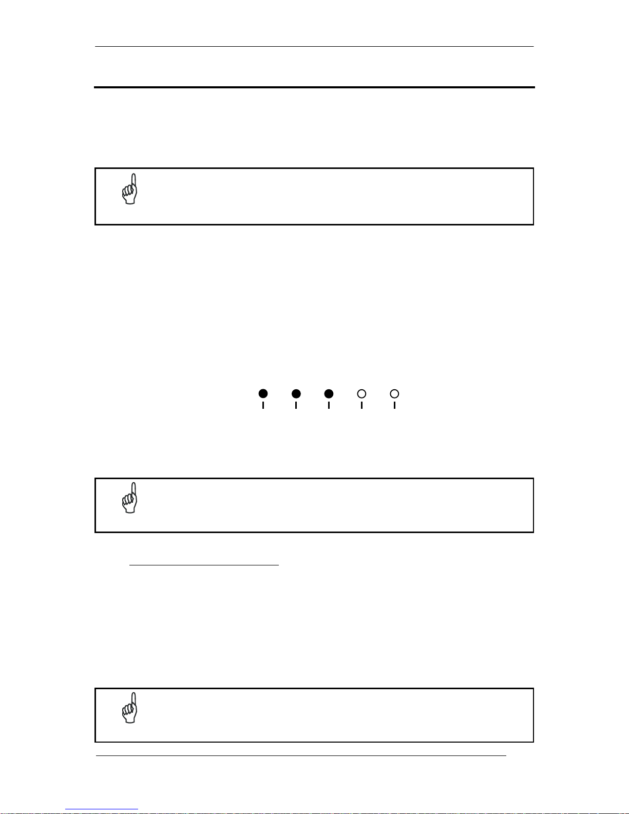
STEP 9 – TEST MODE
Use a code suitable to your application to test the reading performance of the system.
1. Enter the Test function by pressing and holding the X-PRESS™ push button until the
Test LED is on.
2. Release the button to enter the Test function.
Once entered, the Bar Graph on the five LEDs is activated and when codes are placed
in the reading area (FOV), the Bar-Graph shows the Good Read Rate. In case of no
read condition, only the STATUS LED is on and blinks.
Figure 15 – X-PRESS™ Interface: Test Function
3. To exit the Test, press the X-PRESS™ push button once.
NOTE
By default, the Test exits automatically after three minutes.
The Bar Graph has the following meaning:
READY
SETUP
FOCUS
TEST LEARN
GOOD TRIGGERCOM STATUS
red yellow yellow green green
READY
SETUPFOCUSTEST LEARN
GOOD TRIGGER COM STATUS
20% 40% 60% 75% 95%
Page 21

MATRIX 450™ QUICK REFERENCE GUIDE
21
ADVANCED READER CONFIGURATION
For further details on advanced product configuration, refer to the complete Reference
Manual and the Matrix 450™ Help On Line on the installation Mini-DVD.
The following are alternative or advanced reader configuration methods:
Advanced Configuration Using VisiSet™
Advanced configuration can be performed through the VisiSet™ program by selecting
Device>Get Configuration From Temporary Memory to open the Parameter Setup window in
off-line mode. Advanced configuration is addressed to expert users being able to complete a
detailed reader configuration. The desired parameters can be defined in the various folders
of the Parameter Setup window and then sent to the reader memory (either Temporary or
Permanent):
Figure 16 - VisiSet™ Parameter Setup Window
Host Mode Programming
The reader can also be configured from a host computer using the Host Mode programming
procedure, by commands via the serial interface. See the Host Mode Programming file on
the Mini-DVD.
Alternative Layouts
If you need to install an Ethernet network, ID-NET™ network, Fieldbus network, etc., refer to
the Matrix 450™ Reference Manual.
The reader can also be setup for alternative layouts by reading programming barcodes. See
the "Setup Procedure Using Programming Barcodes" printable from the Mini-DVD.
Page 22

MATRIX 450™ QUICK REFERENCE GUIDE
22
APPENDIX
X-PRESS™ is the intuitive Human Machine Interface designed to improve ease of
installation and maintenance.
Status information is clearly presented by means of the five colored LEDs, whereas the
single push button gives immediate access to the following relevant functions:
Learn to self-detect and auto-configure for
reading unknown codes.
Setup to perform Exposure Time and Gain
calibration.
Focus/Locate to turn on the Blue Diamonds™
to aid focusing and the laser pointer LEDs to
aid positioning.
Test with bar graph visualization to check
static reading performance.
In normal operating mode the colors and meaning of the five LEDs are illustrated in the
following table:
READY
green LED indicates the device is ready to operate
GOOD
green LED confirms successful reading
TRIGGER
yellow LED indicates the status of the reading phase
COM
yellow LED indicates active communication on the main serial port*
STATUS
red LED indicates a NO READ result
* When connected to a Fieldbus network through the CBX500, the COM LED is always active, even in
the absence of data transmission, because of polling activity on the Fieldbus network.
During the reader startup (reset or restart phase), all the LEDs blink for one second.
Reader power is indicated by the blue Power LED (located near the Power connector).
Power can be applied to the reader either through the 19-pin male Power connector or the
M12 8-pin male LT-03x Lighting System connector.
The yellow Ethernet Network Presence LED (near the Ethernet connector), indicates
connection to the on-board Ethernet network.
Figure 17 – Power and On-Board Ethernet Network LEDs
On-board Ethernet
Network Presence LED
Power LED
Ethernet MAC Address
Label
Lighting System Signal,
Power Connector
On-board Ethernet
Connector
Power, Serial Host,
I/O Connector
Page 23

MATRIX 450™ QUICK REFERENCE GUIDE
23
REFERENCE READING DIAGRAMS
The following reading diagrams are to be considered as references and are given for
typical performance at 25°C using high quality grade A symbols: Code 128 (1D code) and
Data Matrix ECC 200 (2D code) from the Test Charts provided with the reader.
Testing should be performed with the actual Matrix 450™ + LT-03x assembly using
application codes in order to evaluate whether maximizing application performance
requires adjustments to the HW/SW configuration with respect to the Reference
Conditions given under each diagram.
The ratio of the Vertical FOV width with respect to the Horizontal FOV width in the
diagrams is about equal to 0.84; specifically 2050/2448. (i.e. FOV
V.
FOVH x 0.84).
The focus distance and reading distance ranges are measured from the Lens Cover
window surface.
When using a 25 mm focal length lens (LNS-1225), it is possible to use Super Narrow
Angle Lighting Systems (LT-030 or LT-031) as well as the Narrow Angle Lighting System
LT-032. It is suggested to use the LT-032 in applications with very low contrast codes
and in all cases where the higher lighting power of the LT-030 isn't necessary. LT-030
and LT-031 Lighting Systems are especially effective in high speed code movement
applications.
When defining a HW/SW configuration for the Matrix 450™ + LT-03x assembly for
conditions different from those of the reference diagrams, it is suggested to keep in mind
the following rules:
Changes in the diaphragm aperture influence the depth of field (reading distance
range) and the luminosity of the image. Increasing the the diaphragm aperture by
one stop (i.e. from F/8 to F/5.6 or from F/11 to F/8) doubles the luminosity of the
image, but can cause significant reduction in the reading distance range.
Changes in Exposure Time act directly proportional to the luminosity of the image
and inversely proportional to the maximum code reading movement speed.
Consequently, reducing the Exposure Time by half, reduces the luminosity of the
image by half but doubles the theoretical code reading movement speed.
Changes in Gain act directly proportional to the luminosity of the image.
Increasing the Gain value however, can reduce the quality of the acquired image.
The LT-030 lighting power (at the center of the field of view) is about equal to
twice that of the LT-031 and 3.5 times that of the LT-032.
For example, for the purpose of only changing the luminosity of the image, the
following three adjustments are equivalent:
increase the the diaphragm aperture by one stop;
double the Exposure Time;
double the Gain.
Page 24

MATRIX 450™ QUICK REFERENCE GUIDE
24
Matrix 450™ + LNS-1216
CONDITIONS:
Hardware Settings
Code Symbology Code 128
Code Resolution 0.38 mm (15 mils) 0.50 mm (20 mils)
Focal Length 16 mm
Aperture Stop F/8
Focus Distance 1.200 mm (47.2 inches) 1.400 mm (55.1 inches)
PPI 94 84
Tilt Angle 45°
Skew Angle 15°
Lighting System LT-032 LT-032
Software Parameters
Exposure Time (×10µs) 19 25
Max code moving speed 1.8 m/s 1.8 m/s
Gain 13 14
LT-03x Lighting Mode Very High Power Strobed or Continuous High Power
Minimum Code Height (mm) 5
Code 128 Narrow Margins Enabled
Image Processing Mode Advanced Code Setting
Reading Distance
Horizontal Reading Width
Code 1D 0.38 mm (15 mils) Code 1D 0.50 mm (20 mils)
(in)
(cm)
30
20
0
10
50
40
-30
-20
-10
-50
-40
12
8
0
4
16
-12
-8
-4
-16
80 100 120 140 150 200190 180 170 16013011090 70
28 40 60 8044 48 52 56 64 68 72 7632 36
Page 25

MATRIX 450™ QUICK REFERENCE GUIDE
25
Matrix 450™ + LNS-1225
CONDITIONS:
Hardware Settings
Code Symbology Code 128
Code Resolution 0.33 mm (13 mils) 0.38 mm (15 mils)
Focal Length 25 mm
Aperture Stop F/5.6
Focus Distance 1.700 mm (66.9 inches) 1.900 mm (74.8 inches)
PPI 100 90
Tilt Angle 45°
Skew Angle 15°
Lighting System LT-030 LT-031 LT-032 LT-030 LT-031 LT-032
Software Parameters
Exposure Time (×10µs) 15 16 20 12 12 19
Max code moving speed 1.8 m/s 1.8 m/s 1.5 m/s 2.8 m/s 2.8 m/s 1.8 m/s
Gain 7 13 16 8 16 15
LT-03x Lighting Mode Very High Power Strobed or Continuous High Power
Minimum Code Height (mm) 5
Code 128 Narrow Margins Enabled
Image Processing Mode Advanced Code Setting
Reading Distance
Horizontal Reading Width
Code 1D 0.33 mm (13 mils) Code 1D 0.38 mm (15 mils)
(in)
(cm)
15
10
0
5
25
20
-15
-10
-5
-25
-20
-30
-35
30
35
6
4
0
2
8
-6
-4
-2
-8
10
12
14
-10
-12
-14
145 155 165 175 180 205 200 195 190185170160150 140
210 215
56 62 72 82 64 66 68 70 74 76 78 80
60 58 84
Page 26

MATRIX 450™ QUICK REFERENCE GUIDE
26
Matrix 450™ + LNS-1225
CONDITIONS:
Hardware Settings
Code Symbology Code 128 Data Matrix ECC 200
Code Resolution 0.30 mm (12 mils) 0.61 mm (24 mils)
Focal Length 25 mm
Aperture Stop F/5.6
Focus Distance 1.600 mm (63.0 inches) 1.700 mm (66.9 inches)
PPI 106 100
Tilt Angle 45°
Skew Angle 15°
Lighting System LT-030 LT-031 LT-032 LT-030 LT-031 LT-032
Software Parameters
Exposure Time (×10µs) 12 12 18 16 16 22
Max code moving speed 2.3 m/s 2.3 m/s 1.5 m/s 3.2 m/s 3.2 m/s 2.5 m/s
Gain 7 14 16 6 12 16
LT-03x Lighting Mode Very High Power Strobed or Continuous High Power
Minimum Code Height (mm) 5
Code 128 Narrow Margins Enabled
Module Size (mils) 24
Image Processing Mode Advanced Code Setting
Reading Distance
Horizontal Reading Width
Code 1D 0.30 mm (12 mils) Code 2D 0.61 mm (24 mils)
(in)
(cm)
15
10
0
5
25
20
-15
-10
-5
-25
-20
-30
-35
30
35
6
4
0
2
8
-6
-4
-2
-8
10
12
14
-10
-12
-14
130 140 150 160 165 190 185 180 175170155145135 125
195
50 56 66 76 58 60 62 64 68 70 72 74
54 52 78
Page 27

MATRIX 450™ QUICK REFERENCE GUIDE
27
Matrix 450™ + LNS-1235
CONDITIONS:
Hardware Settings
Code Symbology Code 128
Code Resolution 0.25 mm (10 mils) 0.30 mm (12 mils)
Focal Length 35 mm
Aperture Stop F/11 F/8
Focus Distance 1.800 mm (70.9 inches) 2.300 mm (90.5 inches)
PPI 140 110
Tilt Angle 45°
Skew Angle 15°
Lighting System LT-030 LT-031 LT-030 LT-031
Software Parameters
Exposure Time (×10µs) 20 40 15 27
Max code moving speed 1.0 m/s 0.5 m/s 1.8 m/s 1.0 m/s
Gain 22 22 18 22
LT-03x Lighting Mode Very High Power Strobed or Continuous High Power
Minimum Code Height (mm) 5
Code 128 Narrow Margins Enabled
Image Processing Mode Advanced Code Setting
Reading Distance
Horizontal Reading Width
Code 1D 0.25 mm (10 mils) Code 1D 0.30 mm (12 mils)
(in)
(cm)
30
20
0
10
40
-30
-20
-10
-40
12
8
0
4
16
-12
-8
-4
-16
150 170 190 210 220 260250240 230 200180160 140
56 68 8872 76 80 84 92 96 100
6460
Page 28

MATRIX 450™ QUICK REFERENCE GUIDE
28
MECHANICAL DIMENSIONS
M 5 x 8 n°3
150
[5.91]
213
[8.39]
202
[7.95]
5
[0.20]
130
[5.12]
200
[7.87]
179
[7.05]
90
[3.54]
9
[0.35]
65
[2.56]
30
[1.18]
62
[2.44]
5
0
°
2
5
°
27.5
[1.08]
34.5
[1.36]
55
[2.17]
45
[1.77]
9
[0.35]
22.5
[0.89]
42.5
[1.67]
20
[0.79]
20
[0.79]
60
[2.36]
Figure 18 – Matrix 450™ + LT-03x + L-Bracket Overall Dimensions
compact assembly
standard assembly
mm
in
202
[7.95]
130
[5.12]
5
[0.20]
125
[4.92]
143
[5.61]
62.5
[2.46]
Ø
213
[8.39]
Page 29

MATRIX 450™ QUICK REFERENCE GUIDE
29
TECHNICAL FEATURES
ELECTRICAL FEATURES
Power
Supply Voltage 24 Vdc ± 20%
Consumption (max) 2.5 A ( 0.5A Matrix 450™; 2A LT-03x )
Communication Interfaces
Main
- RS232
- RS485 full-duplex
- RS485 half-duplex
2400 to 115200 bit/s
2400 to 115200 bit/s
2400 to 115200 bit/s
Auxiliary - RS232 2400 to 115200 bit/s
ID-NET™ Up to 1MBaud
Ethernet 1000 Mbit/s, Gigabit Ethernet
Inputs
Input 1(External Trigger) and Input 2 Opto-coupled and polarity insensitive
Max. Voltage 30 Vdc
Max. Input Current 10 mA
Outputs
Output 1 and Output 2 Opto-coupled
V
Out
(I
Load
= 0 mA) Max.
24 Vdc
V
Out
(I
Load
= 10 mA) Max.
1.8 Vdc
PD = V
Out
x I
Load
Max.
170 mW
OPTICAL FEATURES
Image Sensor CCD
Image Format 2448 x 2050
Frame Rate 15 frames/sec.
Pitch
35°
Tilt 0° - 360°
Lighting System
(LT-03x Family Illuminators)
Risk 2 Group LED product to EN62471
Class 2 LED product to IEC60825-1
Laser Safety Class (pointers) Class 2 Laser Light to IEC60825-1
ENVIRONMENTAL FEATURES
Operating Temperature2
0 to 50 C (32 to 122 °F)
Storage Temperature
-20 to 70 C (-4 to 158 °F)
Max. Humidity 90% non condensing
Vibration Resistance3
1.5 mm @ 5 to 9 Hz; 0.5 g @ 9 to 150 Hz 2 hours on each axis
EN 60068-2-6 2 g @ 70 to 200 Hz; 2 hours on each axis
Shock Resistance 30g; 11 ms;
EN 60068-2-27 3 shocks on each axis
Protection Class4
EN 60529
IP65
2
High ambient temperature applications should use metal mounting bracket for heat dissipation.
3
When operating in high vibration environments use two L-shaped mounting brackets and mount the anti-vibration kit for
C-mount lenses, see "Accessories" in the Matrix 450™ Reference Manual.
4
Requires correct connection to IP67 cables with seals and Lens Cover mounting.
Page 30

MATRIX 450™ QUICK REFERENCE GUIDE
30
PHYSICAL FEATURES
Dimensions
Matrix 450™
Matrix 450™ + LT-03x
123 x 64 x 143 mm (4.8 x 2.5 x 5.6 in)
202 x 213 x 179 mm (8.0 x 8.4 x 7.1 in)
Weight (with lens and LT-03x) 3000 g. (6.6 lbs.)
Material Aluminium
SOFTWARE FEATURES
Readable Code Symbologies
1-D and stacked 2-D POSTAL
PDF417 (Standard and
Micro PDF417)
Code 128 (GS1-128)
Code 39 (Standard and
Full ASCII)
Code 32
MSI
Standard 2 of 5
Matrix 2 of 5
Interleaved 2 of 5
Codabar
Code 93
Pharmacode
EAN-8/13 - UPC-A/E
(including Addon 2 and
Addon 5)
GS1 DataBar Family
Composite Symbologies
Data Matrix ECC 200 (Standard,
GS1 and Direct Marking)
QR Code (Standard and
Direct Marking)
MicroQR Code
MAXICODE
Aztec Code
Australia Post
Royal Mail 4 State
Customer
Kix Code
Japan Post
PLANET
POSTNET
POSTNET (+BB)
Intelligent Mail
Swedish Post
Operating Mode
O
NE SHOT, CONTINUOUS, PHASE MODE
Configuration Methods
X-PRESS™ Human Machine Interface
Windows-based SW (VisiSet™) via serial or Ethernet link
Serial Host Mode Programming via serial or Ethernet link
Parameter Storage
Permanent memory (Flash)
USER INTERFACE
LED Indicators Power, Ready, Good; Trigger; Com, Status, (Ethernet
Network); (Green Spot); (Red Spot); Laser Pointers
Keypad Button Configurable via VisiSet™
PATENTS
This product is covered by one or more of the following patents:
Design patents: EP 1,950,486.
Utility patents: US6,512,218 B1; US6,616,039 B1; US6,808,114 B1; US6,997,385 B2;
US7,053,954 B1; US7,102,116 B2; US7,282,688 B2; US7,387,246 B2; US7,433,590 B2;
US7,468,499 B2; US8,058,600 B2; US8,113,430 B2; EP996,284 B1; EP999,514 B1;
EP1,014,292 B1; EP1,128,315 B1; EP1,396,811 B1; EP1,413,971 B1; EP1,804,089 B1;
JP4,435,343 B2; CN ZL200680050007,8.
Additional patents pending.
Page 31

MATRIX 450™ QUICK REFERENCE GUIDE
31
COMPLIANCE
See the Matrix 450™ Reference Manual for the Declaration of Conformity.
Only connect Ethernet and dataport connections to a network which has routing only within the plant
or building and no routing outside the plant or building.
EMC COMPLIANCE
In order to meet the EMC requirements:
connect reader chassis to the plant earth ground by means of a flat copper braid shorter than
100 mm;
connect pin "Earth" of the CBX connection box to a good Earth Ground;
POWER SUPPLY
This product is intended to be installed by Qualified Personnel only.
This product is intended to be connected to a UL Listed Computer which supplies power directly to the
reader or a UL Listed Direct Plug-in Power Unit marked LPS or “Class 2”.
CE COMPLIANCE
Warning: This is a Class A product. In a domestic environment this product may cause radio
interference in which case the user may be required to take adequate measures.
FCC COMPLIANCE
Modifications or changes to this equipment without the expressed written approval of Datalogic could
void the authority to use the equipment.
This device complies with PART 15 of the FCC Rules. Operation is subject to the following two
conditions: (1) This device may not cause harmful interference, and (2) this device must accept any
interference received, including interference which may cause undesired operation.
This equipment has been tested and found to comply with the limits for a Class A digital device,
pursuant to part 15 of the FCC Rules. These limits are designed to provide reasonable protection
against harmful interference when the equipment is operated in a commercial environment. This
equipment generates, uses, and can radiate radio frequency energy and, if not installed and used in
accordance with the instruction manual, may cause harmful interference to radio communications.
Operation of this equipment in a residential area is likely to cause harmful interference in which case
the user will be required to correct the interference at his own expense.
LT-03X LASER SAFETY
The LT-03x Series Lighting Systems contain two
aiming Laser LEDs used to position the reader.
Therefore the product is classified as a Class 2 laser
product according to IEC 60825-1 regulations and
as a Class II laser product according to CDRH
regulations. Disconnect the power supply when
opening the device during maintenance or
installation to avoid exposure to hazardous laser
light. The laser beam can be switched on or
off through a software command.
CRUS
This product is covered by one or more of following patents:
U.S. Pat.: 6,808,114 B1; 6,997,385 B2; 7,387,246 B2.
See product manual and package for entire patent listing.
DATALOGIC AUTOMATION S.r.l.
Page 32

MATRIX 450™ QUICK REFERENCE GUIDE
32
SERIAL NUMBER REFERENCES
Place the replicate, lens, and illuminator serial number labels here for reference. Some of
this information can also be written in the Reader Information configuration parameters in the
Miscellaneous folder in VisiSet™.
Serial Numbers
Matrix 450™
Lens
Illuminator
 Loading...