

Page 1

LaneHawk
TM
Intelligent Lighting and Camera Unit
Quick Reference Guide
Page 2

Datalogic ADC, Inc.
959 Terry Street
Eugene, OR 97402
USA
Telephone: (541) 683-5700
Fax: (541) 345-7140
© 2013 - 2015 Datalogic ADC, Inc.
An Unpublished Work - All rights reserved. No
part of the contents of this documen-
tation or the procedures described therein may be reproduced or transmitted in any
form or b
y any means without prior written permission of Datalogic ADC, Inc. or its
subsidiaries or affiliates ("Datalogic" or “Datalogic ADC”). Owners of Datalogic products are hereby granted a non-exclusive, revocable license to reproduce and transmit this documentation for the purchaser's own internal business purposes.
Pur
chaser shall not remove or alter any proprietary notices, including copyright
notices, contained in this documentation and shall ensure that all notices appear on
any reproductions of the documentation.
Should future revisions of this manual be publis
hed, you can acquire printed versions by contacting your Datalogic representative. Electronic versions may either be
downloadable from the Datalogic website (www.datalogic.com) or provided on
appropriate media. If you visit our website and would like to make comments or
suggestions about this or other Datalogic publications, please let us know via the
"Contact Datalogic" page.
Disclaimer
Datalogic has taken reasonable measures to provide information in this manual
that
is complete and accurate, however, Datalogic reserves the right to change any
specification at any time without prior notice.
Datalogic and the Datalogic logo are registered trademarks of Datalogic S.p.A. in
many
countries, including the U.S.A. and the E.U. All other brand and product names
may be trademarks of their respective owners.
LaneHawk is a registered trademark of Datalogi
c ADC, Inc. in the U.S.A. and the E.U.
Patents
See
www.patents.datalogic.com for patent list.
See the Regulatory Addendum included with your product
for additional regulatory, saf
ety and legal information.
Page 3

Quick Reference Guide 1
Quick Reference Guide
Introduction
These instructions provide basic connection and usage
information for the LaneHawk
TM
intelligent lighting and camera
unit that operates as a Bottom of Basket (BoB) loss prevention
unit.
Nomenclature and Labeling
Figure 1 shows the unit, its cables and the position of the labels
and connector bulkhead on its back side. Labels are shown here
only fo
r the purpose of indicating their location. For actual label
content, view the labels on the product itself.
Figure 1. Nomenclature and Labeling
3
4
6
7
8
5
2
1
9
1 Serial Num./Regulatory Label 6 Ethernet Cable
2 Connector Bulkhead 7 AC Adapter
3 Illumination Panel 8 IEC Power Cable
4Window 9 Top
5 Status Lights
Page 4

2 LaneHawkTM BoB
Connection
Plug in the cables on the unit’s back side (usually beneath the
counter). The Ethernet Cable (#1 in Figure 2) should be plugged in
first to LaneHawk, then to the appropriate ethernet wall jack.
Next, plug the power connector from the AC adapter (#2 in Figure
2) into LaneHawk, then finish by plugging the IEC Power
Cable (#8
in Figure 1) into the adapter (#7 in Figure 1), and its other end into
the power outlet (#4 in Figure 2).
For your convenience, the power plug has been
marked with a red tie wrap (#3 in
Figure 2
) for
easy identification.
Figure 2. Connect the Cables
1
2
3
4
1Ethernet Cable 3Red Tie Wrap
2 Power Connector 4 Power Plug
The unit will take approximately 30 seconds to boot-up. During
this cycle, the status lights viewed through the window in the
front of the unit will flash, except the red (power) light will be on
continuously as soon as power is applied.
NOTE
Page 5

Connection
Quick Reference Guide 3
Start-up Sequence
Refer to Figure 3. In normal operation, after the unit has bootedup, the status lights will settle. The Red Power Light (#2 in the
illustration) should be on ste
adily and the adjacent Amber
Ethernet Link status light (#3) should flash. After a few seconds,
the first Green LaneHawk Server Status Light (#4), next to the
Amber Ethernet Link Light, should flash, then remain on steadily.
Shortly after that, the illumination panel (#1) should turn on.
Figure 3. Viewing the Status Lights and Illumination Panel
2
1
3
4
1 Illumination Panel 3 Amber Ethernet Link Status Light
2 Red Power Status
Light
4 Green LaneHawk Server Status Light
Page 6

4 LaneHawkTM BoB
Communication with the POS
When boot-up has completed, the POS monitor should display
an indication that LaneHawk is connected. The examples in
Figure 4, Figure 5, Figure 6 and Figure 7 show evidence that the
LaneHawk function is active.
Your POS screen may not resemble the samples
below, since POS equipment and software will vary
from site to site.
Figure 4. Example 1 Monitor Screen
21
Soap
Soda
Soda Too
oap
S
NOTE
1 *LH* = LaneHawk has
detected a BoB (Bottom of
Basket) item
2 On = LaneHawk is enabled
Page 7

Communication with the POS
Quick Reference Guide 5
Figure 5. Example 2 Monitor Screen
21
Soda
Figure 6. Example 3 Monitor Screen
21
1 CONN = Connected 2 *LH* = LaneHawk has detected a
BoB (Bottom of Basket) item
1 Bottom of Basket = LaneHawk
is enabled (can function) on
this POS
2 LaneHawk is connected
Page 8
6 LaneHawkTM BoB
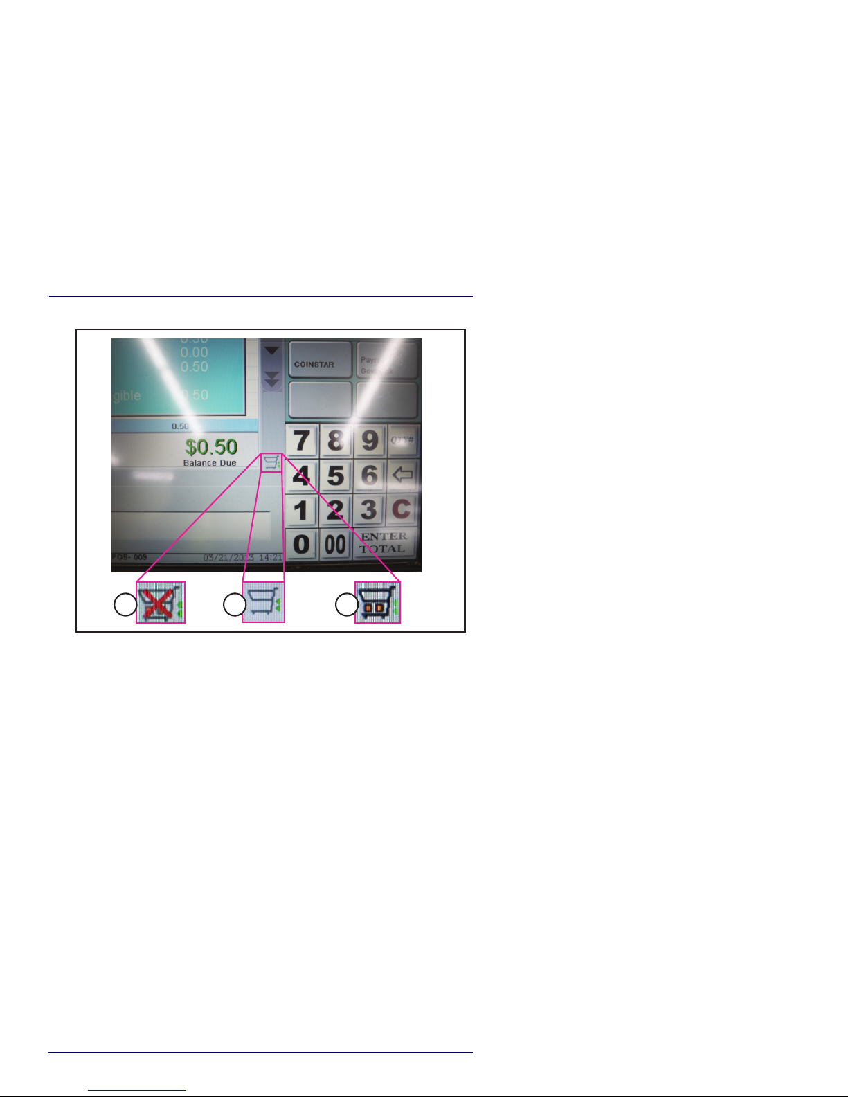
Figure 7. Example 4 Monitor Screen
1 2 3
1 LaneHawk is not connected 3 LaneHawk has recognized a
BoB (Bottom of Basket) item
2 LaneHawk is connected
Page 9

Maintenance
Quick Reference Guide 7
Maintenance
The LaneHawk unit requires only routine cleaning of its window
using a soft, lint-free cloth dampened with an ammonia-based
window cleaner.
The window should also be periodically i
nspected for cracks,
scratches or other damage which could inhibit performance.
Contact your service provider if there is window damage.
Figure 8. Cleaning the Window
1
2
3
DO NOT use abrasive cleaning agents or abrasive pads
to clean this product. Harsh chemicals, disinfectants,
and cleansers can cause damage which will adversely
affect the unit’s performance.
CAUTION
Page 10

8 LaneHawkTM BoB
Status Lights
Here is the definition of each of the five status lights as identified
in
Figure 8:
1Red Power
Light
Power
2Amber
Ethernet
Link Status
Light
Network connection status:
Flashing = Data is transferring on the network. (ie,
the network connection is active)
3Green
LaneHawk
Server
Status Light
Connection to the LaneHawk server:
Flashing = has connected to the network (has an IP
address and can communicate on the network)
Solid = has connected successfully with the
LaneHawk server.
Page 11

Troubleshooting
Quick Reference Guide 9
Troubleshooting
If the suggested solutions in the table below are unsuccessful,
take note of the current condition of the status lights, then
contact your service provider to resolve any problems.
SYMPTOM POSSIBLE PROBLEM SOLUTION
Red Power Light
is off
No power Ensure that all power
connections are secure.
Verify that the power outlet
is live.
Amber Ethernet
Link Status Light
is off
Ethernet is not
connected
Check that the ethernet cable
is securely connected at the
unit and at the network
switch.
No network
communication
After checking that ethernet
connections are secure, cycle
power to the LaneHawk unit.
Verify that the network
switch is powered on.
Confirm that the port on the
network switch is working.
Green
LaneHawk
Server Status
Light is flashing
Network connection
is live, but there is no
communication with
the LaneHawk
server.
Verify that the LaneHawk
server is up and running.
Check that the Ethernet
cable is securely connected
at the unit and at the
network switch.
Verify that the Ethernet cable
is securely connected at the
LaneHawk server and at the
network switch.
After checking that Ethernet
connections are secure, cycle
power to the LaneHawk unit.
LaneHawk
performance
has degraded
unexpectedly
The window is dirty Clean the window
Other problems Contact your service provider
Page 12

10 LaneHawkTM BoB
Warranty
Datalogic warrants to Customer that this product will be free from defects in
materials and workmanship for a period of 30 days from product shipment.
Datalogic ADC Limited Factory Warranty
Warranty Coverage
Datalogic ADC (“Datalogic”) hardware products are warranted against defects in
material and workmanship under normal and proper use. The liability of
Datalogic under this warranty is limited to furnishing the labor and parts
necessary to remedy any defect covered by this warranty and restore the
product to its normal operating condition. Repair or replacement of product
during the warranty does not extend the original warranty term. Products are
sold on the basis of specifications applicable at the time of manufacture and
Datalogic has no obligation to modify or update products once sold.
If Datalogic determines that a product has defects in material or workmanship,
Datalogic shall, at its sole option repair or replace the product without
additional charge for parts and labor, or credit or refund the defective products
duly returned to Datalogic. To perform repairs, Datalogic may use new or
reconditioned parts, components, subassemblies or products that have been
tested as meeting applicable specifications for equivalent new material and
products. Customer will allow Datalogic to scrap all parts removed from the
repaired product. The warranty period shall extend from the date of shipment
from Datalogic for the duration published by Datalogic for the product at the
time of purchase (Warranty period). Datalogic warrants repaired hardware
devices against defects in workmanship and materials on the repaired
assembly for a 90 day period starting from the date of shipment of the repaired
product from Datalogic or until the expiration of the original warranty period,
whichever is longer. Datalogic does not guarantee, and it is not responsible for,
the maintenance of, damage to, or loss of configurations, data, and applications
on the repaired units and at its sole discretion can return the units in the
“factory default” configuration or with any software or firmware update
available at the time of the repair (other than the firmware or software installed
during the manufacture of the product). Customer accepts responsibility to
maintain a back up copy of its software and data.
Warranty Claims Process
In order to obtain service under the Factory Warranty, Customer must notify
Datalogic of the claimed defect before the expiration of the applicable Warranty
period and obtain from Datalogic a return authorization number (RMA) for
return of the product to a designated Datalogic service center. If Datalogic
determines Customer’s claim is valid, Datalogic will repair or replace product
without additional charge for parts and labor. Customer shall be responsible for
packaging and shipping the product to the designated Datalogic service center,
with shipping charges prepaid. Datalogic shall pay for the return of the product
Page 13

Troubleshooting
Quick Reference Guide 11
to Customer if the shipment is to a location within the country in which the
Datalogic service center is located. Customer shall be responsible for paying all
shipping charges, duties, taxes, and any other charges for products returned to
any other locations. Failure to follow the applicable RMA policy, may result in a
processing fee. Customer shall be responsible for return shipment expenses
for products which Datalogic, at its sole discretion, determines are not defective
or eligible for warranty repair.
Warranty Exclusions
The Datalogic Factory Warranty shall not apply to:
(i) any product which has been damaged, modified, altered, repaired or
upgraded by other than Datalogic service personnel or its authorized
representatives;
(ii) any claimed defect, failure or damage which Datalogic determines was
caused by faulty operations, improper use, abuse, misuse, wear and tear,
negligence, improper storage or use of parts or accessories not approved
or supplied by Datalogic;
(iii) any claimed defect or damage caused by the use of product with any
other instrument, equipment or apparatus;
(iv) any claimed defect or damage caused by the failure to provide proper
maintenance, including but not limited to cleaning the upper window in
accordance with product manual;
(v) any defect or damage caused by natural or man-made disaster such as
but not limited to fire, water damage, floods, other natural disasters, vandalism or abusive events that would cause internal and external component damage or destruction of the whole unit, consumable items;
(vi) any damage or malfunctioning caused by non-restoring action as for
example firmware or software upgrades, software or hardware reconfigurations etc.;
(vii) the replacement of upper window/cartridge due to scratching, stains or
other degradation and/or
(viii) any consumable or equivalent (e.g., cables, power supply, batteries, key-
pads, touch screen, triggers etc.).
No Assignment
Customer may not assign or otherwise transfer its rights or obligations under
this warranty except to a purchaser or transferee of product. No attempted
assignment or transfer in violation of this provision shall be valid or binding
upon Datalogic.
DATALOGIC'S LIMITED WARRANTY IS IN LIEU OF ALL OTHER WARRANTIES,
EXPRESS OR IMPLIED, ORAL OR WRITTEN, STATUTORY OR OTHERWISE,
INCLUDING, WITHOUT LIMITATION, ANY IMPLIED WARRANTIES OF
MERCHANTABILITY, FITNESS FOR A PARTICULAR PURPOSE, OR
NONINFRINGEMENT. DATALOGIC SHALL NOT BE LIABLE FOR ANY DAMAGES
SUSTAINED BY CUSTOMER ARISING FROM DELAYS IN THE REPLACEMENT OR
Page 14

12 LaneHawkTM BoB
REPAIR OF PRODUCTS UNDER THE ABOVE. THE REMEDY SET FORTH IN THIS
WARRANTY STATEMENT IS THE CUSTOMER’S SOLE AND EXCLUSIVE REMEDY
FOR WARRANTY CLAIMS. UNDER NO CIRCUMSTANCES WILL DATALOGIC BE
LIABLE TO CUSTOMER OR ANY THIRD PARTY FOR ANY LOST PROFITS, OR ANY
INCIDENTAL, CONSEQUENTIAL IN-DIRECT, SPECIAL OR CONTINGENT DAMAGES
REGARDLESS OF WHETHER DATALOGIC HAD ADVANCE NOTICE OF THE
POSSIBILITY OF SUCH DAMAGES.
Risk of Loss
Customer shall bear risk of loss or damage for product in transit to Datalogic.
Datalogic shall assume risk of loss or damage for product in Datalogic’s
possession. In the absence of specific written instructions for the return of
product to Customer, Datalogic will select the carrier, but Datalogic shall not
thereby assume any liability in connection with the return shipment.
Page 15

Page 16

820068514 (Rev B) March 2015
© 2013 - 2015 Datalogic ADC, Inc. All rights reserved.
Datalogic and the Datalogic logo are registered trademarks of
Datalogic S.p.A. in many countries, including the U.S.A. and the E.U.
Datalogic ADC, Inc.
959 Terry Street | Eugene |OR 97402 | USA
Telephone: (1) 541-683-5700
|
Fax: (1) 541-345-7140
www.datalogic.com
 Loading...