

Page 1
Multi-Purpose Device for Retail
User’s Manual
Page 2

Datalogic S.r.l.
Via S. Vitalino, 13
40012 Lippo di Calderara di Reno
Bologna - Italy
Telephone: (+39) 051-3147011
Fax: (+39) 051-3147205
©2016 Datalogic S.r.l.
An Unpublished Work - All rights reserved. No part of the contents of this documentation or the procedures described therein may be reproduced or transmitted in any form or by any means without prior written permission of
Datalogic S.r.l. or its subsidiaries or affiliates. Owners of Datalogic products
are hereby granted a non-exclusive, revocable license to reproduce and transmit this documentation for the purchaser's own internal business purposes.
Purchaser shall not remove or alter any proprietary notices, including copyright notices, contained in this documentation and shall ensure that all
notices appear on any reproductions of the documentation.
Should future revisions of this manual be published, you can acquire printed
versions by contacting your Datalogic representative. Electronic versions may
either be downloadable from the Datalogic website (www.datalogic.com) or
provided on appropriate media. If you visit our website and would like to make
comments or suggestions about this or other Datalogic publications, please
let us know via the "Contact Datalogic" page.
Datalogic has taken reasonable measures to provide information in this manual that is complete and accurate, however, Datalogic reserves the right to
change any specification at any time without prior notice.
Datalogic and the Datalogic logo are registered trademarks of Datalogic S.p.A.
in many countries, including the U.S.A. and the E.U.
JOYA is a trademark of Datalogic S.p.A. or of Datalogic Group companies, registered in many countries, including the U.S. and the E.U.
All other brand and product names may be trademarks of their respective
owners.
Patent. See www.patents.datalogic.com
Disclaimer
Patents
for patent list.
Page 3

Table of Contents
Introduction ....................................................................... 1
Conventions ..................................................................................1
Product Presentation ..................................................................2
Available Models ..........................................................................3
Out of the Box ...............................................................................5
General View .................................................................................6
Front View ........................................................................................ 6
Back View ......................................................................................... 7
Top View ........................................................................................... 8
Side View .......................................................................................... 8
Accessories ...................................................................................9
Battery............................................................................. 11
Install the Battery ..................................................................... 11
Charge the Battery .................................................................... 13
Fast Charge .................................................................................... 13
Standard Charge ............................................................................14
Battery Safety Guidelines ......................................................... 17
Use and Functioning...................................................... 21
Getting Started .......................................................................... 21
Taskbar ....................................................................................... 23
Touch Gestures .......................................................................... 24
Data Capture .............................................................................. 25
Imager Data Capture .....................................................................25
Resetting the JOYA TOUCH ....................................................... 28
Warm Boot ..................................................................................... 28
Cold Boot ......................................................................................... 29
User’s Manual i
Page 4

Clean Boot ...................................................................................... 29
Control Panel ..............................................................................31
Data Capture Configuration .......................................................... 32
DL Buttons ..................................................................................... 50
Persistent Registry ....................................................................... 52
Wireless Communications ............................................................ 54
Audio Settings ................................................................................ 62
Connecting to other Computers ...............................................65
Windows Mobile® Device Center ................................................. 65
Datalogic Firmware Utility ........................................................66
Retrieving a Firmware Image Update ......................................... 66
Installing DFU on the Host PC ...................................................... 67
Updating the Firmware ................................................................. 68
Datalogic Desktop Utility ...........................................................69
Administrative Options (Admin tab) ............................................ 70
Locked Web Browser Options (LockedWeb tab) ........................ 75
Status Icons Options (Status Tab) ............................................... 77
Windows Control ........................................................................... 78
AppSelector Options (AppSelect tab) ........................................... 80
Locked Web Browser .................................................................83
FlashDisk Directory File Management ....................................84
Connections ..................................................................... 87
USB Connection ..........................................................................87
USB Direct Connection .................................................................. 87
Wi-Fi Connection ........................................................................88
Bluetooth® Serial Connection ...................................................90
Wireless and Radio Frequencies Warnings ............................92
Technical Features.......................................................... 95
Technical Data ............................................................................95
Decode Distances .......................................................................99
Test Codes..................................................................... 101
Maintenance................................................................. 109
ii JOYA™ TOUCH
Page 5

Cleaning the Device ................................................................. 109
Ergonomic Recommendations .............................................. 110
Safety and Regulatory Information............................ 111
General Safety Rules ............................................................... 111
Power Supply ........................................................................... 112
Laser Safety ............................................................................. 113
LED Class .................................................................................. 121
Marking and European Economic Area (EEA) ...................... 121
Statement of Compliance ....................................................... 122
Radio Technologies and Frequency Bands ........................... 125
Information for the User ............................................................. 126
FCC/IC Labeling ....................................................................... 127
FCC Compliance ....................................................................... 127
ISED Compliance ...................................................................... 129
Radiofrequency Radiation Exposure Information ............... 131
WEEE Compliance ................................................................... 132
Support.......................................................................... 135
Reference Documentation ..................................................... 135
Warranty Terms and Conditions ........................................... 135
Glossary......................................................................... 137
User’s Manual iii
Page 6

NOTES
iv JOYA™ TOUCH
Page 7

Introduction
Conventions
This manual uses the following conventions:
‘Device’ and 'JOYA TOUCH' refer to the JOYA TOUCH.
‘Dock’ refers to the JOYA TOUCH 3-Slot Cradle.
The label artworks may be only a draft. Refer to the product labels
for more precise information.
User’s Manual 1
Page 8

Introduction
Product Presentation
The Datalogic JOYA TOUCH is a pocket-sized Windows embedded
compact 7 powered mobile computer, available in two form factors.
This compact, lightweight, and versatile device, combines fully
integrated automatic data capture (2D bar code), a wireless charging
system and wireless communication capabilities, supporting nearly
any application.
The Datalogic JOYA TOUCH system architecture is based on the blend
of Intel X-Scale series processors coupled with the Windows
Embedded Compact operating system and it was developed to meet
the most demanding customer needs.
A huge quantity of on-board memory is available. It enables the user
to adapt the terminal for any specific need.
Thanks to its great ergonomics and the state of the art architecture,
the Datalogic JOYA TOUCH is the right answer to enhance
your business opportunities.
2JOYA™ TOUCH
Page 9

Introduction
Available Models
The Datalogic JOYA TOUCH is available in different models
depending on the features it is equipped with. All options are listed
below:
• p/n 911350010 JOYA TOUCH Plus Handheld, FWVGA Full
Touch color display 4.3” in diagonal, white-illumination 2D
imager engine, Green Spot, radio 802.11 A/B/G/N, 512MB
RAM, 1GB Flash + 4GB SD, Bluetooth Dual Mode V.4, Windows
Embedded Compact 7 with dedicated SDK for developing 3rd
party applications. Wavelink Avalanche® device management
preloaded. Gray/Blue colors combination (upper case /
battery cover).
This model is available also in other colors combinations
(indicated colors represent front housing/battery cover):
- 911350014 Grey/Grey
- 911350015 Grey/Red
- 911350020 Blue/Yellow
- 911350021 Orange/Orange
- 911350022 Green/Green
• p/n 911350011 JOYA TOUCH Plus Pistol Grip, FWVGA Full
Touch color display 4.3” in diagonal, white-illumination 2D
imager engine, Green Spot, radio 802.11 A/B/G/N, 512MB
RAM, 1GB Flash + 4GB SD, Bluetooth Dual Mode V.4, Windows
Embedded Compact 7 with dedicated SDK for developing 3rd
party applications. Wavelink Avalanche® device management
preloaded. Grey/Blue/Blue colors combination (upper case /
trigger / battery cover).
User’s Manual 3
Page 10

Introduction
This model is available also in other colors combinations (indicated
colors represent front housing/battery cover/trigger):
- 911350012 Grey/Grey/Blue
- 911350013 Grey/Red/Red
- 911350016 Yellow/Yellow/Yellow
- 911350017 Red/Grey/Grey
- 911350018 Grey/Orange/Orange
- 911350019 Grey/Green/Green
• p/n 911350023. JOYA TOUCH Basic Handheld, FWVGA Full
Touch color display 4.3” in diagonal, white-illumination 2D
imager engine, Green Spot, radio 802.11 A/B/G/N, 512MB
RAM, 512GB Flash, Windows Embedded Compact 7 with
dedicated SDK for developing 3rd party applications. Wavelink
Avalanche® device management preloaded. Gray/Red colors
combination (upper case / battery cover).
• p/n 911350024 JOYA TOUCH Basic Pistol Grip, FWVGA Full
Touch color display 4.3” in diagonal, white-illumination 2D
imager engine, Green Spot, radio 802.11 A/B/G/N, 512MB
RAM, 512GB Flash, Windows Embedded Compact 7 with
dedicated SDK for developing 3rd party applications. Wavelink
Avalanche® device management preloaded. Grey/Red/Red
colors combination (upper case / trigger / battery cover).
For further details about the Datalogic JOYA TOUCH models refer to
the web site: www.datalogic.com.
4JOYA™ TOUCH
Page 11

Introduction
Out of the Box
The JOYA TOUCH package contains:
•JOYA TOUCH (device)
• Rechargeable battery
•Quick Start Guide
•Safety & Regulatory Addendum
• EULA Addendum
Remove all the components from their packaging; check their
integrity and compare them with all the packing documents.
Keep the original packaging for use when sending
products to the technical assistance center. Damage
caused by improper packaging is not covered under the
CAUTION
warranty.
User’s Manual 5
Page 12
Introduction
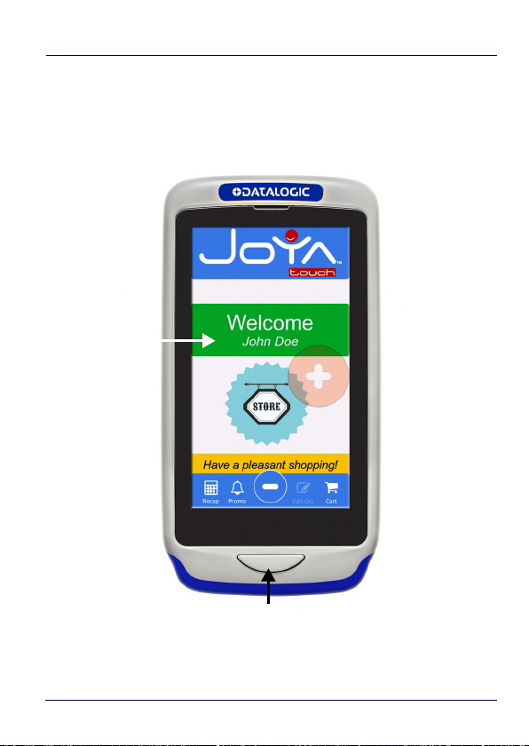
Home Key
Touch Panel
Display
General View
Front View
6JOYA™ TOUCH
Page 13
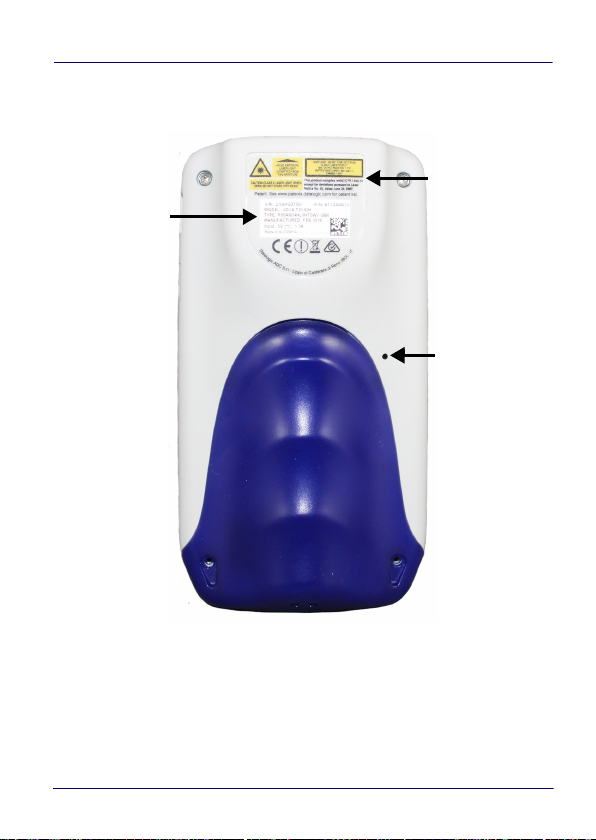
Back View
Laser Safety
Label
Product
Label
Cold Boot
Button
Introduction
User’s Manual 7
Page 14
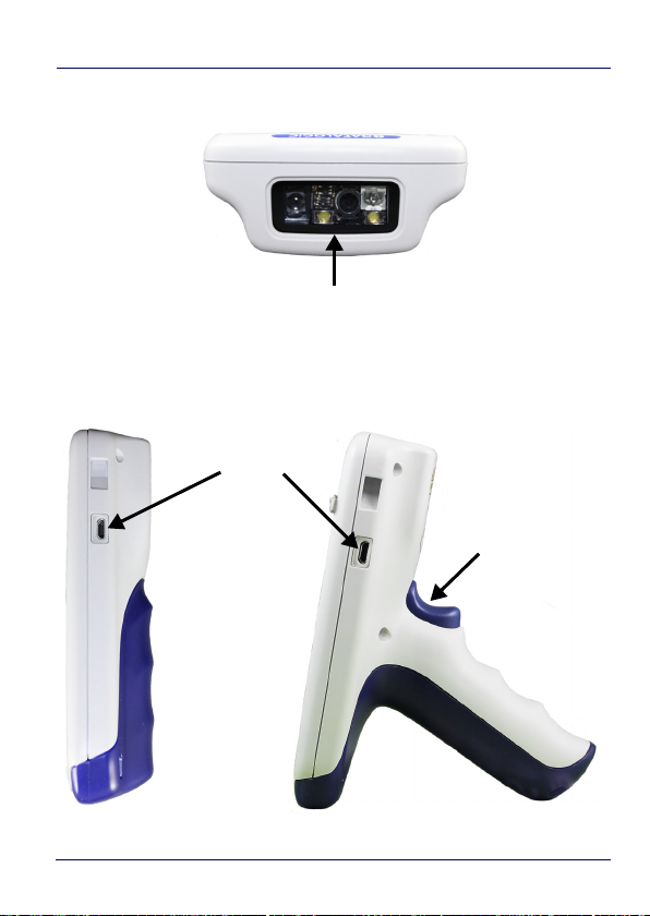
Introduction
Data Capture Window
Scan Trigger
Micro USB Port
Handheld Models
Pistol Grip Models
Top View
Side View
8JOYA™ TOUCH
Page 15

Introduction
Accessories
Cradle
91ACC0043 JOYA TOUCH 3-Slot Cradle
Cradle Accessories
91ACC0045 JOYA TOUCH Cradle Unlock Key (5 PCS)
91ACC0048 JOYA TOUCH 3-Slot Cradle Power Supply. Line Cord
required (max 2 cradles on standard charge, max 1
cradle on fast charge per power supply)
91ACC0049 JOYA TOUCH Cradle Power Jumper (5 PCS)
91ACC0050 JOYA TOUCH 3-Slot Cradle Wall Bracket
91ACC0051 Blue Kit to convert Plus Handheld to a Pistol Grip
91ACC0052 Blue Kit to convert Plus Pistol Grip to a Handheld
91ACC0053 Blue Kit to convert Basic Handheld to a Pistol
Grip
91ACC0054 Blue Kit to convert Basic Pistol Grip to a Handheld
Batteries
91ACC0055 JOYA TOUCH Replacement Battery 3.75V 3030 mAh
Various
91ACC0047 JOYA TOUCH Trolley Holder (60pieces)
Use only Datalogic-approved power supply and cables.
Use of an alternative power supply will invalidate any
NOTE
User’s Manual 9
approval given to this device and may be dangerous.
Page 16

Introduction
NOTES
10 JOYA™ TOUCH
Page 17
Battery
Handheld Models
Pistol Grip Models
Handheld Models
Pistol Grip Models
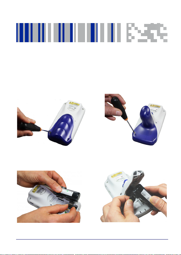
Install the Battery
To install the battery pack, follow the steps below:
1. Unscrew the battery cover and remove it:
2. Connect the battery contacts to the battery clip located in the
battery slot:
User’s Manual 11
Page 18
Battery
Handheld Models
Pistol Grip Models
Handheld Models
Pistol Grip Models
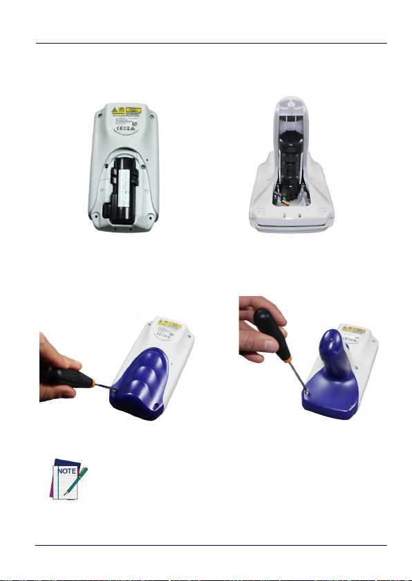
3. Insert the battery pack into the slot as shown in the figures
below:
4. Insert the battery cover and fix the screws:
Required torque of the screws is 35 cNm.
NOTE
12 JOYA™ TOUCH
Page 19
Battery
High Visibility
High Density
Charge the Battery
The JOYA TOUCH battery pack is not initially fully charged. After
installing the battery, charge it with the 3-slot cradle.
The device needs to be inserted head down into the cradle.
Charge the battery for a minimum of 7 hours in standard
charge and 3 hours in fast charge.
NOTE
There are two options to connect the cradle to the power supply:
fast charge and standard charge.
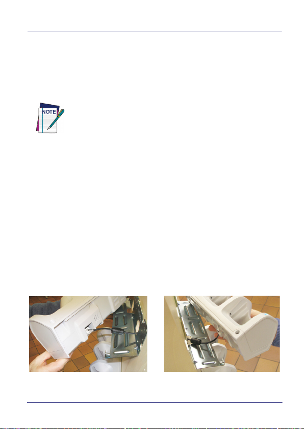
Fast Charge
The fast charge connection allows to power one cradle with one
power supply.
Plug the power supply cable into the power connector on the back of
the cradle, then plug the power supply into the AC/DC plug using a
Datalogic power cable.
Please see below an example of how to insert the power supply
cable through the wall mounting metal bracket:
User’s Manual 13
Page 20
Battery
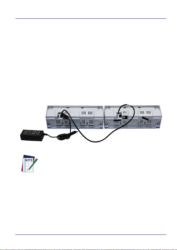
Standard Charge
The standard charge connection allows to power two cradles with
one power supply.
To connect a second cradle use the JOYA TOUCH Cradle Power
Jumper, available as optional accessory (P/N 91ACC0049).
1. Connect the first cradle to the second cradle using the power
jumper.
2. Connect the power supply to the first cradle.
3. Plug the power supply into the AC/DC plug using a Datalogic
power cable.
For further information on the JOYA TOUCH 3-Slot Cradle,
refer to the JOYA TOUCH 3-Slot Cradle Quick Start Guide,
included in the cradle’s box, and to the JOYA TOUCH 3-Slot
NOTE
Cradle Installation Guide, downloadable from our website
www.datalogic.com.
By default, the main battery pack is disconnected at the factory to
avoid damage due to excessive draining.
Rechargeable battery pack is less than half of full charge when
delivered.
14 JOYA™ TOUCH
Page 21

Battery
The battery pack autonomy varies according to many factors, such
as the frequency of bar code scanning, RF usage, battery life,
storage, environmental conditions, etc.
Close to the limits of the working temperature, some battery
performance degradation may occur.
The JOYA TOUCH should be charged at an ambient temperature
between 0 - 35º C (32 to 95ºF) to achieve the maximum charging
rate.
Never charge the device battery in a closed space where excessive
heat can build up.
As a safety precaution, the battery may stop charging to avoid
overheating.
The JOYA TOUCH may get warm during charging; this is normal and
does not mean a malfunction.
Even if the storage temperature range is wider, it is recommended
to store the terminal and the batteries at environmental
temperature, in order to achieve the longest battery life.
Avoid storing batteries for long periods in a state of full
charge or very low charge.
We recommend charging the battery pack every two to
CAUTION
three months to keep its charge at a moderate level to
maximize battery life.
Annual replacement of rechargeable battery pack
avoids possible risks or abnormalities and ensures
maximum performance.
User’s Manual 15
Page 22

Battery
CAUTION
WARNING
Do not incinerate, disassemble, short terminals, or
expose to high temperature. Risk of fire and explosion.
Use specified charger only. Risk of explosion if the
battery is replaced by an incorrect type. Dispose of
batteries as required by local authorities.
Use only Datalogic approved batteries and accessories
for battery charging.
Risk of explosion if battery is replaced by an incorrect
type.
Dispose of used batteries according to the instructions.
Il y a risque d’explosion si la batterie est remplacée par
une batterie de type incorrect.
Mettre au rebut les batteris usagées confor mément
aux instructions.
16 JOYA™ TOUCH
Page 23

Battery Safety Guidelines
Installing, charging and/or any other action should be
done by authorized personnel and following this
manual.
WARNING
The battery pack may get hot, explode, ignite, and/or
cause serious injury if exposed to abusive conditions.
If the battery pack is replaced with an improper type,
there is risk of explosion.
Do not place the battery pack in or near a fire or other
heat source; do not place the battery pack in direct
sunlight, or use or store the battery pack inside
unventilated areas in hot weather; do not place the
battery pack in microwave ovens, in clothes dryers, in
high pressure containers, on induction cook surfaces
or similar devices. Doing so may cause the battery
pack to generate heat, explode or ignite. Using the
battery pack in this manner may also result in a loss
of performance and a shortened life expectancy.
To power the cradle, use only a Datalogic approved
power supply. The use of an alternative power supply
will void the product warranty, may cause product
damage and may cause heat, an explosion, or fire.
The area in which the units are charged should be
clear of debris and combustible materials or
chemicals.
Do not use the battery pack of this terminal to power
devices other than this mobile computer.
Battery
User’s Manual 17
Page 24

Battery
WARNING
Immediately discontinue use of the battery pack if,
while using, charging or storing the battery pack, the
battery pack emits an unusual smell, feels hot, changes
color or shape, or appears abnormal in any other way.
Do not short-circuit the battery pack contacts
connecting the positive terminal and negative
terminal. This might happen, for example, when you
carry a spare battery pack in your pocket or purse;
accidental short–circuiting can occur when a metallic
object such as a coin, clip, or pen causes direct
connection of the contacts of the battery pack (these
look like metal strips on the battery pack). Short–
circuiting the terminals may damage the battery pack
or the connecting object.
Do not apply voltages to the battery pack contacts.
Do not pierce the battery pack with nails, strike it with
a hammer, step on it or otherwise subject it to strong
impacts, pressures, or shocks.
Do not disassemble or modify (i.e. bend, crush or
deform) the battery pack. The battery pack contains
safety and protection devices, which, if damaged, may
cause the battery pack to generate heat, explode or
ignite.
In case of leakage of liquid from the battery, avoid
contact with liquid the skin or eyes. If the contact
occurs, immediately wash the affected area with water
and consult a doctor.
Do not solder directly onto the battery pack.
Do not expose the battery pack to liquids.
18 JOYA™ TOUCH
Page 25

WARNING
Battery
Avoid any knocks or excessive vibrations. If the device
or the battery is dropped, especially on a hard surface,
you should take it to the nearest Authorised Repair
Centre for inspection before continuing to use it.
If your device stops working for any reason, do not use
its battery on other electronic devices without a prior
check and approval by an Authorised Repair Centre.
Do not replace the battery pack when the device is
turned on.
Do not remove or damage the battery pack’s label.
Do not use the battery pack if it is damaged in any
part.
Battery pack usage by children should be supervised.
Collect and recycle waste batteries separately from
the device in compliance with European Directive
2006/66/EC, 2011/65, 2002/96/EC and subsequent
modifications, with US and China regulatory laws and
regulations about the environment.
User’s Manual 19
Page 26

Battery
NOTES
20 JOYA™ TOUCH
Page 27
Use and Functioning
The use of the JOYA TOUCH depends on the application software
loaded. However, there are several parameters that can be set and
utilities that can be used to perform some basic functions such as
data capture, communications, file management, etc. Furthermore,
Avalanche Enabler is a major utility embedded in the software
provided from factory.
Getting Started
The JOYA TOUCH turns on when a charged battery pack is inserted.
User’s Manual 21
Page 28

Use and Functioning
The mobile computer goes into power-off (low power with display
and keyboard backlight off), when it is no longer used for more than a
programmable timeout, which is defined in the POWER applet of the
Control Panel. In this mode it can be awakened (resuming operation)
pressing the Home key.
The mobile computer can also be awakened or turned off
by the application program.
NOTE
22 JOYA™ TOUCH
Page 29
Use and Functioning
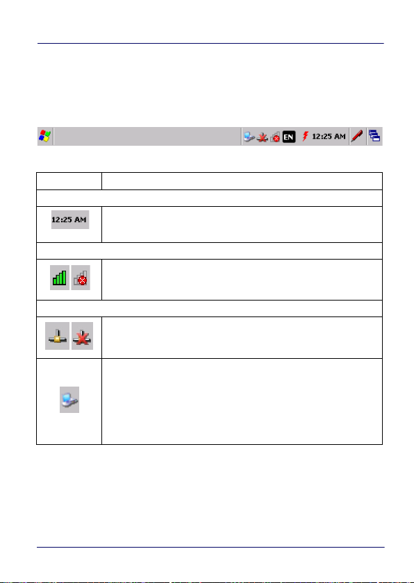
Taskbar
The Taskbar provides information about the time, the battery level,
the keyboard function, and the decoding status.
ICON DESCRIPTION
Time Icons
It displays the time.
Radio Status Icons
It indicates if the radio is connected or not with an Access Point.
Network Status Icons
It displays whether you are connected or not to Wi-Fi or
Bluetooth Personal Area Network.
ActiveSync connection icon is displayed when connected to
ActiveSync or Windows Mobile Device Center either by USB or
Bluetooth. Double-tap it to open a status dialog that will let you
disconnect the ActiveSync session without physically
disconnecting the device from the PC. It is the only way to
disconnect a Bluetooth ActiveSync connection.
User’s Manual 23
Page 30
Use and Functioning
Touch Gestures
Double Tap
Drag
Tap-and-hold
CAUTION
Touch the screen twice to open items and select options.
Touch and slide your finger on screen to select text and
images. Drag in a list to select multiple items.
Tap and hold your finger on an item to see a list of actions
available for that item. On the pop-up menu that appears, tap
the action you want to perform.
To prevent damage to the screen, do not use sharp
devices or any device other than your finger or a touch
screen stylus.
In harsh applications, use of screen protectors should
be taken into consideration, in order to extend the
touch screen operating life.
Do not apply not necessary high pressures on the
screen.
For applications where an intensive use of the touch
screen is foreseen, please consider that touch screen
components are subject to progressive wear.
24 JOYA™ TOUCH
Page 31

Use and Functioning
Data Capture
To capture data, first of all double-tap Control Panel > Decoding and
open the applet.
Imager Data Capture
The imager uses digital camera technology to take a digital picture
of a bar code, the image is stored in memory and software decoding
algorithms are executed to extract the data from the image. The
omnidirectional scanning does not require that the operator orient
the bar code to align with the scan pattern.
To scan a bar code symbol:
1. Point the scan window at the bar code.
User’s Manual 25
Page 32

Use and Functioning
2. Press the home key. The imager projects a laser aiming pattern
similar to those used on cameras. The aiming pattern is used to
position the bar code or object within the field of view.
3. Center the symbol in any orientation within the aiming pattern.
Ensure the entire symbol is within the rectangular area formed
by the brackets in the aiming pattern, then either wait for the
timeout or release the home key to capture the image. A red
beam illuminates the symbol, which is captured and decoded.
Linear Bar Code
26 JOYA™ TOUCH
2D Matrix Symbol
Page 33

Use and Functioning
If the scan has been successful:
• If enabled, the good read beep plays.
• If enabled, the GreenSpot projects a green spot onto the bar
code image.
• If enabled, a pop-up window will report the data and the
symbology of the scanned bar code (See “Data Capture
Configuration” on page -32).
The field of view changes its size as you move the reader closer or
farther away from the bar code. The aiming pattern is smaller when
the imager is closer to the bar code and larger when it is farther
from the bar codebar code.
Scan symbols with smaller bars or elements (mil size) closer to the
unit and those with larger bars or elements (mil size) farther from
the unit. Hold the JOYA TOUCH between two and nine inches
(depending on symbol density) from the symbol, centering the
aiming pattern cross hairs on the symbol.
User’s Manual 27
Page 34

Use and Functioning
Resetting the JOYA TOUCH
There are three reset methods for the JOYA TOUCH.
A ”warm boot” terminates an unresponsive application and clears
the working RAM, but preserves both the file system and the
registry.
A ”cold boot” forces all applications to close and clears working RAM
and files not resident on the persistent flash memory. Registry is
restored from persistent memory if available or returned to factory
default.
A ”clean boot” restore the JOYA TOUCH to factory default.
Warm Boot
A warm boot terminates an unresponsive application and clears the
working RAM, but preserves the file system and registry. If an
application "hangs" initiate a warm boot to terminate the application.
To perform a warm boot, tap Start > Programs > Warm Boot:
28 JOYA™ TOUCH
Page 35

Use and Functioning
Cold Boot
A cold boot is a complete reset of the JOYA TOUCH in which all
applications are forcibly closed and RAM is completely cleared.
Registry is restored from persistent memory if a saved copy is
available (see Persistent Registry on page 52) and RAM file system
completely erased. You will lose any applications and data (registry
too) which are not stored in persistent flash memory.
A cold boot is necessary when the Windows Embedded Compact 7
operating system locks up and the warm boot command does not
work.
To perform a cold boot, lightly press with a metallic clip inside the
circle hole on the back for 10 seconds.
Clean Boot
A clean boot is a complete restore to factory default and backup
folder content erase of the JOYA TOUCH. You will loose any
applications and data (registry too).
To perform a clean boot first execute a cold boot while keeping
pressed the Home key.
A pop-up will ask you to confirm, confirm by pressing and releasing
the Home key for three times, or wait for 3 seconds to cancel.
User’s Manual 29
Page 36

Use and Functioning
Clean boot may require a considerable amount of time,
even a few minutes.
NOTE
Registry
Flash Disk
(Backup Folder)
Object Store
(RAM Disk)
Storage Card
(if present)
CAUTION
Warm Boot Cool Boot Clean Boot
Restored from the latest
Preserved
Preserved Preserved Cleared
Preserved
Preserved Preserved Preserved
Before performing a reset, it is recommended to:
• Execute a system backup to keep your more
important files and applications persistent.
• Save the registry to non-volatile memory to
guarantee the persistence of the Windows
configuration.
persistent copy (from
flash)
Reinitialized, some
persistent files could be
restored (from flash)
Reinitialized
Reinitialized
30 JOYA™ TOUCH
Page 37

Use and Functioning
Control Panel
From the home screen, double-tap My Device icon or tap Start
>Settings and then double-tap Control Panel icon to open the
control panel main window.
User’s Manual 31
Page 38

Use and Functioning
Data Capture Configuration
From the control panel main window, double tap the Decoding icon:
There are two sections in the Decoding control panel, each containing
additional pages. There are eight general configuration pages and
multiple bar code symbology pages.
32 JOYA™ TOUCH
Page 39

Use and Functioning
Configure
Select the desired configuration from the options shown in the
figure below, and the other Decoding Properties figures on the
following pages.
Select General, 1D or 2D Bar Code, then use the menu or tap the left
and right arrow keys to navigate the different pages of the Decoding
utility. The menu options will change to reflect the items most
recently selected.
User’s Manual 33
Page 40

Use and Functioning
Notification
From the Decoding Properties page, tap Configure > General >
Notification. Use to configure the good read green spot, tone and
vibration notification.
Number
Sets the number of notifications (green spot, beep or vibration) the
scanner emits on a good read.
Duration
Sets the duration of the notification (green spot, beep or vibration)
the scanner emits on a good read.
Interval
Sets the interval between each notification (green spot, beep or
vibration) the scanner emits on a good read.
Volume
Sets the volume of beep tone.
34 JOYA™ TOUCH
Page 41

Use and Functioning
Beep Tone
Sets the type of beep tone.
Good Read
From the Decoding Properties page, tap Configure > General > Good
Read. Use it to enable good read notifications (green spot, vibrator)
and to set the decoding timeout for decoding labels.
Select Automatic good read to enable/disable notifications (main
enabler), then select the notification you want to use.
User’s Manual 35
Page 42

Use and Functioning
Formatting
From the Decoding Properties page, tap Configure > General >
Formatting. Allows to format the bar code text by enabling and
configuring the use of prefix, suffix and data separator.
Label Prefix
Select Label prefix to enter the characters you will be using as prefix.
Scroll the Add special dropdown menu to select a special character to
be added in the current cursor position.
Label Suffix
Select Label suffix to enter the characters you will be using as suffix.
Scroll the Add special dropdown menu to select a special character to
be added in the current cursor position.
36 JOYA™ TOUCH
Page 43

Use and Functioning
General Options
From the Decoding Properties page, tap Configure > General >
General Options.
Label Programming Enable
Parameter reserved to Datalogic personnel.
User’s Manual 37
Page 44

Use and Functioning
Symbology ID
Scroll the Symbology ID dropdown menu to add a code identifier
prefix or suffix to the bar code string.
The AIM ID (Association for Automatic Identification and Mobility) is
an international bar code identifier. When AIM IDs Before is enabled,
the AIM ID is inserted at the beginning of the decoded bar code.
DL IDs is a Datalogic specific character identifier.
User IDs is a user specific character identifier you can set in the
related symbology settings menu.
38 JOYA™ TOUCH
Page 45

Use and Functioning
Group Separator Replacement
The group separator replacement is a non printable data separator
character (ASCII code 1D hex). Use the Group separator replacement
to select a special character that will be used as GS data separator
substituting the standard GS character.
Remove Non-printable Characters
Select it to remove non-printable characters from a unicode string.
User’s Manual 39
Page 46

Use and Functioning
Decoding Options
From the Decoding Properties page, tap Configure > General >
Decoding Options. Use it to configure the User ID for symbologies,
Redundancy and Aggressive Decoding (if supported by the decoding
module). Select a symbology to view or change the available
properties settings.
40 JOYA™ TOUCH
Page 47

Use and Functioning
Imager Options
From the Decoding Properties page, tap Configure > General >
Imager Options. Use it to customize the JOYA TOUCH scanning
behavior.
Enable Illumination
If selected, it causes the scanner to turn on the illumination to aid
decoding.
Enable Picklist
If selected, it allows you to pick and decode a bar code from multiple
bar codes printed close together, when the scan illumination
intersects more than one bar code. Only the targeted bar code will
be returned.
User’s Manual 41
Page 48

Use and Functioning
Target Mode
If enabled, when the scan button is pressed, the scanner will project
an aiming pattern to assist in centering over the bar code before
scanning. Scroll the Target mode dropdown menu to select the
desired targeting behavior:
No Delay
Target mode is disabled.
42 JOYA™ TOUCH
Page 49

Use and Functioning
Target Timeout
If selected, scanning takes place after a programmable time upon
pressing the scan button. Drag the Timeout slider to set the
maximum amount of time the scanner attempt to decode after
target timeout:
Release Scan
If selected, scanning takes place after the scan button is released.
Drag the Timeout slider to set the scanning timeout after releasing
the scan button:
User’s Manual 43
Page 50

Use and Functioning
Multi Scan
The JOYA TOUCH scanner allows you to scan multiple bar codes by
one scan. From the Decoding Properties page, tap Configure >
General > Multi Scan and drag the Labels per good read slider to set
the number of bar codes allowed to be read per scan.
Select Enable indicators for each label to enable notifications for
each bar code thet is scanned.
44 JOYA™ TOUCH
Page 51

Use and Functioning
Keyboard Wedge
From the Decoding Properties page, tap Configure > General >
Keyboard Wedge. Select Bar code to enable the wedge mode.
User’s Manual 45
Page 52

Use and Functioning
1D Bar Code Symbology Pages
Each bar code symbology can be customized with additional settings
that may affect that specific bar code decoding. Scroll the drop-down
menus from Configure > 1D Bar Code, or tap the left and right arrow
keys to navigate the 1D bar code symbology pages and configure
symbology decoding options:
46 JOYA™ TOUCH
Page 53

Use and Functioning
Refer to the sample symbology control panels for examples of the
types of fields and options you can modify. The sample below shows
the settings of a Code 128 bar code symbology:
User’s Manual 47
Page 54

Use and Functioning
2D Bar Code Symbology Pages
Scroll the drop-down menus from Configure > 2D Bar Code, or tap the
left and right arrow keys to navigate the 1D bar code symbology
pages and configure symbology decoding options:
Refer to the sample symbology control panels for examples of the
types of fields and options you can modify. The sample below shows
the settings of a DataMatrix bar code symbology:
48 JOYA™ TOUCH
Page 55

Use and Functioning
Decoding Settings
Select from the Decoding Properties Settings menu to restore
previous configurations and/or other available default settings.
Choose from:
•Factory Defaults
• Minimum Settings
• Maximum Settings
•Save
• Revert to Saved Settings
The settings are saved when you tap ‘Yes’. To permanently save
these settings you need to save the registry using the Persistent
Registry applet in the Control Panel. When open, Decoding
Properties acts as a simple bar code test tool that provides the Data
decoded and the Data Type of the bar code scanned.
User’s Manual 49
Page 56

Use and Functioning
DL Buttons
You can use the DL Buttons tab to associate specific keys with
specific applications. From the control panel main window, double
tap the DL Buttons icon. As for the Joya Touch, it is possible to
program the Home key and the Trigger, if present.
On the DL Buttons tab, customize the program hardware buttons to
launch your most used applications. Under Select a button, select the
button you want to assign a function to, and then select a program
from Assign a function.
Tap OK to confirm.
50 JOYA™ TOUCH
Page 57

Use and Functioning
Triggers
Triggers are special customizable buttons that are mapped by
default by DL Buttons. Also, they can be set as wakeup buttons:
TRIGGERS AVAILABLE FUNCTIONS
Scan
Pistol Trigger
Bar Code function activates the scanner.
User’s Manual 51
Page 58

Use and Functioning
Persistent Registry
The Registry stores information that are necessary to configure the
system for applications and hardware devices. The Registry also
contains information that the operating system continually
references to during operation. To persist the Registry settings
between boots, do the following steps:
1. Double-tap the Control Panel icon on the home screen.
2. Double-tap the Persistent Registry icon.
3. Tap the Persist button.
4. Tap OK to exit.
52 JOYA™ TOUCH
Page 59

Use and Functioning
To change Persistent Registry timing, do the following steps:
1. Select a time interval from the menu.
2. Tap OK to save and exit.
To deselect Persistent Registry timing, do the following steps:
1. Deselect the Persist registry settings check box.
2. Tap OK to save and exit.
User’s Manual 53
Page 60

Use and Functioning
Wireless Communications
Wireless networking has a customized control, Laird Connection
Manager (LCM), specific to the radio. LCM allows you to view all radio
and security settings, and status. It also enables you to troubleshoot
connectivity issues.
To access LCM, double-tap the Laird Connection Manager icon on the
home screen, or tap Start > Programs > Laird Connection Manager.
Status Tab
The Status tab provides status information on the radio's Wi-Fi
connection between the client device and the access point to which
it's associated.
Status
Indicates the current status of the Laird Wi-Fi radio. Connection
statuses include:
•Down
The radio is not recognized by Laird software and therefore is
not associated or authenticated.
54 JOYA™ TOUCH
Page 61

Use and Functioning
•Disabled
The radio is disabled. To enable the radio, check the Wi-Fi
check box located on the Configuration window. When the
radio is disabled, it does not attempt to make a connection to
an access point.
• Not Associated
The radio has not established a connection to an access point.
• Associated
The radio has established a connection to an access point but
is not EAP authenticated. The radio cannot communicate
unless it is associated and EAP authenticated.
If the Encryption type is set to WEP or Open (None), it can
communicate (send data) while in the Associated state.
NOTE
• Connected to [SSID]
The radio is connected to the named SSID.
IP Address
Displays the IP address of the Wi-Fi device.
Signal Strength
Displays the signal strength (or RSSI) in dBm.
User’s Manual 55
Page 62

Use and Functioning
Configuration Tab
The Configuration tab allows Wi-Fi to be enabled and disabled. It also
allows users to manage and scan for Wi-Fi profiles.
Check on/off box
Check to enable or disable Wi-Fi
Active Profile
Displays the name of the active profile. Use the drop-down menu to
select a different profile.
Profiles
Allows user to change profiles and global configurations, and enables
administrative abilities.
There are two tabs listed under Manage Profiles:
•Wi-Fi - Profile
Profile settings are radio and security settings that are stored
for each configuration profile. The Profile tab displays the
following properties and options:
56 JOYA™ TOUCH
Page 63

Use and Functioning
- Property and Value table: displays the properties of each
profile and its respective value.
- Profile drop-down menu: displays the current profile and
a list of all profiles previously configured or used.
- New: allows a profile to be added to the list.
- Delete: deletes a profile from the list.
- Value box: displays the value of a prospective property.
- Commit: saves the changed value.
•Wi-Fi - Globals
The Globals tab displays the source device's Wi-Fi global
values that apply to all profiles and settings that apply to LCM
itself. The following subsections allow these values to be
modified:
User’s Manual 57
Page 64

Use and Functioning
- Property and Value table: displays various properties and
their respective values.
- Value box: displays the current and avaliable alternative
values for the selected property.
- Commit: saves the changed value.
When you tap Commit, a registry flush occurs for all
settings.
NOTE
58 JOYA™ TOUCH
Page 65

Use and Functioning
Scan
Opens the scan window to scan the area for available SSIDs. Also
displays RSSI and security.
Diagnostics Tab
The Diagnostics tab enables you to troubleshoot connection issues
within LCM.
User’s Manual 59
Page 66

Use and Functioning
Wi-Fi
Status enabled/disabled
About
Tap to display LCM information including driver and the LCM version.
Advanced
Tap to display advanced settings for Wi-Fi, strength percentage, and
quality percentage.
There are three drop-down options:
• Status
60 JOYA™ TOUCH
Page 67

• Ping Tools
• Utilities
Use and Functioning
User’s Manual 61
Page 68

Use and Functioning
Audio Settings
There are two applets that control volume: Audio and Volume &
Sounds.
Audio
From the control panel main window, double-tap the Audio icon:
The audio control panel can be used to independently set the
playback or recording volume for different types of audio inputs and
outputs, such as a headset, powered mobile dock, or the internal
speakers and microphone.
62 JOYA™ TOUCH
Page 69

Use and Functioning
User’s Manual 63
Page 70

Use and Functioning
Volume & Sounds
From the control panel main window, select the Volume & Sounds
applet by double tapping the Volume & Sounds icon:
The Volume & Sounds applet configures audio features of all
speakers and headphones and appears as follows:
64 JOYA™ TOUCH
Page 71

Use and Functioning
Connecting to other Computers
Windows Mobile® Device Center
The desktop application Windows Mobile® Device Center gives you
the ability to synchronize information between a desktop computer
and your JOYA TOUCH.
Synchronization compares the data on the JOYA TOUCH with that on
the desktop computer and updates both with the most recent
information.
Windows Mobile Device Center is only compatible with Windows
Vista and Windows 7; if you run Windows XP or earlier, you have to
download Microsoft ActiveSync.
To establish a partnership between the JOYA TOUCH and a host PC,
start Windows Mobile® Device Center and follow the steps below:
1. Connect the JOYA TOUCH to the host PC. Windows Mobile®
Device Center configures itself and then opens.
2. On the license agreement screen, click Accept.
3. On the Windows Mobile Device Center’s home screen, click Set
up your device.
4. Select the information types that you want to synchronize, then
click Next.
5. Enter a device name and click Set Up.
User’s Manual 65
Page 72

Use and Functioning
Datalogic Firmware Utility
The Datalogic devices are equipped with a field upgradeable firmware
mechanism.
Firmware updates are available on the Datalogic website:
http://www.datalogic.com/eng/support-services/automatic-datac
apture/downloads/software-utilities-sw-2.html.
After you have downloaded the desired update, there are several
ways you can update the firmware on your device.
• Use Wavelink Avalanche™ if you have multiple Datalogic
devices to update. For more information refer to the dedicated
section of the Wavelink website.
• If Wavelink Avalanche™ is not available or you have only a few
Datalogic devices to update, use the Datalogic Firmware Utility
(DFU), described below, to install or update the firmware using
an ActiveSync connection.
The following sections provide procedures for the retrieval and
installation of the most current firmware image onto a Datalogic
device.
Retrieving a Firmware Image Update
The following instructions use Internet Explorer to retrieve the most
current firmware image.
1. Launch Internet Explorer on your PC and navigate to the
Datalogic website.
2. Navigate to the Downloads section of the website.
3. Using the device selection fields, select the file you want to
download, then click Save to begin copying the files to your local
machine (or local network location).
66 JOYA™ TOUCH
Page 73

Use and Functioning
Installing DFU on the Host PC
The Datalogic Firmware Utility (DFU) provides administrators with a
field upgrade mechanism. You must have Microsoft® ActiveSync (for
Windows XP devices) or Windows Mobile® Device Center (for
Windows 7 and Vista devices) already loaded and running on the
host PC to use DFU. See “Windows Mobile® Device Center” on
page -65 for more information.
Prior to installing, you must remove any previous versions
of DFU installed on the host PC.
NOTE
To install the Datalogic Firmware Utility, complete the following
steps on the PC:
1. Go to the Datalogic website and download the most current
version of the Datalogic Firmware Utility. Unzip the file, then
double-click to run DFU_Setup.exe.
2. Click OK to continue once you have removed previous versions of
DFU.
3. The Welcome to DFU Setup Program screen opens.
- Please exit all Windows applications before running this
installer.
-Click Next to continue the Setup.
4. Follow the onscreen instructions to complete the installation.
User’s Manual 67
Page 74

Use and Functioning
Updating the Firmware
After copying the firmware image to the host PC and installing DFU,
you can upgrade the firmware on your Datalogic device.
The following steps require that you have already
established an ActiveSync or Windows Mobile® Device
Center connection between the host computer and the
NOTE
1. Go to Start > Programs > Datalogic > DFU > Datalogic Firmware
Utility.
2. Verify that ActiveSync is selected by clicking Communications >
WMDC/ActiveSync.
3. Click browse (...) and navigate to the location where you saved
the firmware file for your terminal.
4. Select the current *.out file and click Open.
5. Click Update.
6. DFU will compare the selected firmware image with the firmware
already loaded on the device; if the image is compatible with the
connected device, DFU will proceed to update the firmware image
on your device.
After the firmware of your device has been updated, the program will
automatically perform a warm reset of the device.
Datalogic device.
68 JOYA™ TOUCH
Page 75

Use and Functioning
Datalogic Desktop Utility
Datalogic Desktop Utility (DDU) allows administrators to configure
Windows® CE and Embedded Handheld devices to control individual
user access. This includes the ability to:
• Prevent users from changing your device OS settings.
• Use Application Selector to replace the desktop with a
selection of authorized applications.
• Restrict user access in Internet Explorer (and customized
error recovery mechanisms).
To open DDU, access the Control Panel and double-tap the Datalogic
Desktop Utility icon.
User’s Manual 69
Page 76

Use and Functioning
Administrative Options (Admin tab)
When you open the DDU control panel, the Admin tab appears.
COMMAND DESCRIPTION
Enable Datalogic
Desktop
Enter Password
Re-Enter Password
Set Password
Set Defaults
Tap this checkbox to activate the DDU functions such as
Windows Access Restrictions and Application Selector.
Enter a password in the text box. This allows the user to
specify a password when this utility is launched. By
default the password is ”blank”. A password can consist
of all standard keyboard characters.
Carefully re-enter the password in the second text box.
Tap
Set Password
To change or remove the password, enter a new value,
re-enter the new value, and tap
Tap
Set Defaults
functions on all the tabs. After you select this option, you
will receive a prompt to verify this selection.
to enable the password.
Set Password
to reset the default values of all the
.
70 JOYA™ TOUCH
Page 77

Use and Functioning
Setting a Password
To set a password:
1. Enter a password in the field using the virtual keyboard. This
allows the user to specify a password when this utility is
launched. By default the password is ”blank”.
Be sure to record the password for future reference.
NOTE
2. Re-enter the password in the second field.
3. Tap Set Password to enable the password.
4. Tap OK to close the Set Password Confirmation dialog.
User’s Manual 71
Page 78

Use and Functioning
You must tap Set Password prior to exiting DDU in order to
store and activate your new password. It is not necessary
NOTE
to select Enable Datalogic Desktop.
CAUTION
If you tap Set Defaults it will remove all custom
settings and restore all the factory default settings,
except a previously set password.
72 JOYA™ TOUCH
Page 79

Use and Functioning
Changing a Password
To change to a new password:
1. Enter a new value in the Enter Password field.
2. Re-enter the new value in the Re-enter Password field.
3. Tap Set Password.
Removing a Password
To remove a password:
1. Enter blanks in both Password fields.
2. Tap Set Password.
Password Request Dialog Box
Once the password is set, next time you open the Datalogic Desktop
Utility, the DDU Password dialog box opens.
This dialog box will only open if a password was defined:
User’s Manual 73
Page 80

Use and Functioning
1. Type in your password using either the keypad on the unit, or
using the stylus on the soft input panel (SIP). If you enter an
incorrect password, the system will prompt you to input the
correct one.
2. Select/tap OK to verify the password. Or tap X to cancel.
74 JOYA™ TOUCH
Page 81

Use and Functioning
Locked Web Browser Options (LockedWeb tab)
Tap the LockedWeb tab to access the Locked Web Browser
Configuration.
For additional information about Locked Web Browser commands
and metatags, see Locked Web Browser on page 83.
Error Page Redirection
Use the Error Redirection option to provide customized recovery
from common errors. When an error occurs, the browser can
redirect access to a specified error page with instructions on how to
recover from the problem.
Error Redirection Options
The “Error Type” pull-down list displays available Error Types:
(400) Invalid Syntax, (403) Request Forbidden, (404) Object Not
Error Type
Error Page
Found, (406) No Response Format, (410) Page Doesn't Exist,
(500) Internal Server Error, (501) Server Can't Do That, Generic
Error, Network Disconnected.
Edit this textbox to associate a website or html file with the
specified error.
User’s Manual 75
Page 82

Use and Functioning
Other Options
Full Screen
Status Icon
Trap Keys
Other Options
Exit Password
Browser Home
Page
Set the web browser in full screen mode.
Enable or disable the status icons view. The status icons can
be configured on the Status tab of DDU.
When checked:
• all key presses will be trapped by the Locked Web
Browser to prevent the user from accessing unsafe parts
of the system. For example, pressing Ctrl+O to Open a File
will not work;
• safe key presses (e.g. Alpha numeric) will still get
processed by the Locked Web Browser as normal. For
example entering a number in a text field on a web page;
• DL Buttons keys will not work in the LockedWeb Browser;
• all Locked Web Browser command keys will work (e.g.
Ctrl+0 to exit).
When unchecked:
• all keys will be processed normally by the system and the
browser;
• DL Buttons keys will work normally;
• all Locked Web Browser command keys will work (e.g.
Ctrl+0 to exit).
When checked, a password will be required before the Locked
Web Browser can exit. This password is different than the
DDU exit password, with a default value of “0000”.
This sets the Internet Explorer home page, regardless of the
enable state of the Locked Web Browser.
76 JOYA™ TOUCH
Page 83

Use and Functioning
Status Icons Options (Status Tab)
Tap the Status tab to access the Status Icons option. You can
configure the view of some status icons that are used in LockedWeb
and in Application Selector to display the status of Wi-Fi radio and
battery.
Status Icons Options
Icon Size
Icon Location
Sets the status icons’ size.
Selects the preferred location for each status icon.
User’s Manual 77
Page 84

Use and Functioning
Windows Control
Select/tap the Win (Windows Controls) tab to access the Windows
Controls option. Use Windows controls to allow or restrict access to
Windows system functions.
You can disable normal Windows functions such as the taskbar,
leaving nothing but a blank workspace. This allows applications to be
run in full screen mode and prevents users from accidental or
unauthorized use of the taskbar, Internet Explorer, and any other
resident applications.
WIndows Controls
Tap
Show Taskbar
Taskbar Enabled
Start Menu Enabled
AutoSIP Enabled
Show Taskbar
displayed or not.
Tap
Taskbar Enabled
accessible. This option is only available when the
Taskbar
is checked.
Tap
Start Menu Enabled
Menu is displayed or not. This option works only when
Task Bar Enabled
Enables the AutoSIP Windows feature.
to specify whether the Taskbar is
to specify whether the taskbar is
Show
to specify whether the Start
is checked.
78 JOYA™ TOUCH
Page 85

WIndows Controls
Scroll Bars Enabled
Widows CE Desktop
Enabled
Changes require a device reboot.
NOTE
Use and Functioning
This control only takes effect in Locked Web Browser.
When checked, displays horizontal and vertical scroll bars
to help view large web pages which do not fit the screen.
When unchecked, scroll bars will not be present.
When selected, CE Desktop is disabled, so application
icons can’t be activated.
User’s Manual 79
Page 86

Use and Functioning
AppSelector Options (AppSelect tab)
Tap the Application Selector (AppSelect Tab) to edit, add, or delete
applications for the application selector.
Application Selector Options
Tap
Enable Application
Selector
Show status icons
Authorized
Applications
Enable Application Selector
application selector. When enabled, the Application
Selector replaces the desktop and allows only authorized
use of applications.
Enable or disable the status icons view. The status icons
can be configured on the
This is a list of applications that the user can access.
to enable/disable the
Status
tab of DDU.
Application Selector Commands
New
Edit
Del
Up/Down
80 JOYA™ TOUCH
Tap
New
to create a new application entry.
Tap
Edit
to edit the selected entry.
This is a list of applications that the user can access.
Tap
Del
to delete the selected entry.
Page 87

Use and Functioning
Add Applications
The Add Application dialog opens when you tap either New or Edit.
From the Add Application dialog the administrator can configure
and/or add/change a new application entry in the list.
Applications with the Run Application at Startup option enabled will
start automatically when the Application Selector starts up.
COMMAND DESCRIPTION
Application Title
Executable
Browse
Arguments
Type the name of the application in this textbox in the way
you wish it to appear for the user.
Displays the path for the executable file which you want to
run.
Browse for the desired executable file. The results of this
search are placed in the
Type any command line arguments to be used when an
application is executed.
Executable
textbox.
User’s Manual 81
Page 88

Use and Functioning
COMMAND DESCRIPTION
Tap
Set Defaults
Icon File
functions on all the tabs. After you select this option, you
will receive a prompt to verify this selection.
Browse
Run Application at
Startup
Browse for the desired icon file. The results of this search
are placed in the
Tap this box to force this application to auto start when the
Application Selector starts up. Applications will be started
in the order listed in the authorized application list.
Enter a delay duration in seconds in the combo box. This
Delay
option delays auto start of application(s) to allow drivers to
load prior to starting applications.
OK
X
Tap OK to add/save changes.
X Select/tap X to cancel the creation of this entry.
to reset the default values of all the
Icon File
textbox.
82 JOYA™ TOUCH
Page 89

Use and Functioning
Locked Web Browser
The Locked Web Browser is a browser helper object for Internet
Explorer. It allows an administrator to define a restricted internet
usage environment. Once in the restricted environment, a password
is required to exit. This means users can only access web
applications and websites set by the administrator.
To launch the application, go to \Windows\WebAppLock.exe.
Configuration is set up through the DDU control panel. See
Locked Web Browser Options (LockedWeb tab) on page
75
NOTE
In Full Screen mode, status icons may be used to display signal
strength and battery state. For CE, a non-full screen mode exists
that allows the status bar to be displayed but with user interaction
disabled.
The following command line arguments are supported:
• /E optional parameter which allows for Exit without entering
a password
• @URL optional parameter which specifies a URL to use as a
home page.
• /C optional parameter which disables the ctrl keys (including
the one to exit).
for more information.
User’s Manual 83
Page 90

Use and Functioning
FlashDisk Directory File Management
All of the Windows Embedded Compact 7 system files reside in RAM
(volatile memory) except for the FlashDisk directory, which resides in
FLASH (non-volatile memory).
Therefore the contents of the FlashDisk directory are persistent even
if the mobile computer is rebooted or the battery pack is changed.
You can save your more important files that you don't want to lose
due to mobile computer reboot, in the FlashDisk directory or create a
sub-directory within FlashDisk.
Even though the Windows Directory resides in RAM, it often contains
files or sub-directories created by the user or by installation
programs that you don't want to lose at re-boot. To keep these files
persistent it is necessary to copy them to the directory
\FlashDisk\Windows.
This directory doesn't exist originally (only FlashDisk exists), and
therefore it must be created. At the next cold boot, before activating
the shell, Windows Embedded Compact 7 will copy the contents
including all sub-directories of \FlashDisk\Windows to \Windows.
Likewise, to maintain files that must be run at Windows Embedded
Compact 7 startup, (i.e. .exe, .lnk, .vb, .htm, etc.), it is necessary to
copy them to the directory \FlashDisk\Startup.
This directory does not exist originally (only FlashDisk exists), and
therefore it must be created. The applications programs will be run
after any type of re-boot (both software and cold boot).
However, since file system persistence is performed after the
“\FlashDisk\Startup” folder execution, for those programs which
depends upon the DLLs and resources copied from
“\FlashDisk\Windows” to “\Windows” during the cold-boot, the
“\FlashDisk\Windows\dl_startup” folder is to be preferred to
execute programs and applications, since the execution follows the
84 JOYA™ TOUCH
Page 91

Use and Functioning
file system restore (and no DLL and resource dependence failure will
occur).
As an alternative to the Safe Setup function, it is possible to copy the
.cab files to the directory \FlashDisk\Cabfiles (the Cabfiles
sub-directory doesn't exists originally and must therefore be
created) and perform a mobile computer cold boot to have the
application installed.
Once these files are copied to the directory \FlashDisk\Cabfiles, the
application will be run after each re-boot. From the second cold boot
on, a message may be displayed such as "<application name> is
already installed. Reinstall?".
This message blocks the boot process. Press the [Enter] key to
continue the system initialization. In a specific JOYA TOUCH version,
a 4GB DS type card is available as permanent general purposes
storage device (path = \Storage Card).
User’s Manual 85
Page 92

Use and Functioning
NOTES
86 JOYA™ TOUCH
Page 93

Connections
Host
Computer
JOYA TOUCH
Standard Micro USB
cable type USB A –
micro USB B
USB Connection
USB Direct Connection
You can use any standard micro USB cable to directly connect the
Datalogic JOYA TOUCH to a host computer to transfer data through
the USB interface.
NOTE
User’s Manual 87
Connection through the cable complies to USB 2.0
standard.
Page 94

Connections
JOYA TOUCH
JOYA TOUCH
Access Point
Host
Wi-Fi Connection
The JOYA TOUCH Wi-Fi 802.11 a/b/g/n radio models can
communicate with the host using the on-board radio frequency
component and an Access Point connected to the host computer. To
launch this utility you can tap the specific icon if it's visible on the
taskbar or you can open Connections folder or Control Panel from
desktop.
Wi-Fi module is on by default, in order to avoid wasting
energy, you can switch it off using the Wireless
NOTE
88 JOYA™ TOUCH
Communications applet.
Page 95

NOTE
NOTE
Connections
Suspending the terminal powers off the 802.11 a/b/g/n
radio and drops the radio connection. When the terminal
resumes, depending on the radio power mode and
security protocol selected, it may take up to 30 seconds
for the 802.11 a/b/g/n radio driver to re-associate the
radio to the network.
Area coverage and radio performance may vary, due to
environmental conditions, access point types or
interference caused by other devices (microwave ovens,
radio transmitters, etc.).
User’s Manual 89
Page 96

Connections
Bluetooth® Serial Connection
JOYA TOUCH models can communicate with a Bluetooth® printer,
using the on-board Bluetooth® module.
Bluetooth® is only available in Joya Touch plus models.
NOTE
In order to extend battery life, the Bluetooth® module is off
by default. If you need to have Bluetooth® working, the
NOTE
module must be powered on.
Suspending the terminal powers off the Bluetooth® radio
and drops the Bluetooth® connection. When the terminal
resumes, it takes approximately 10 seconds for the
NOTE
90 JOYA™ TOUCH
Bluetooth® radio driver to re-initialize the radio.
Page 97

NOTE
Connections
Area coverage and Bluetooth® radio performance may
vary, due to environmental conditions or interference
caused by other devices (microwave ovens, radio
transmitters, etc.).
User’s Manual 91
Page 98

Connections
Wireless and Radio Frequencies Warnings
Use only the supplied or an approved replacement
antenna. Unauthorized antennas, modifications or
attachments could damage the product and may violate
WARNING
laws and regulations.
Most modern electronic equipment is shielded from RF
signals. However, certain electronic equipment may not
be shielded against the RF signals generated by JOYA
TOUCH.
Datalogic recommends persons with pacemakers or
other medical devices to follow the same
recommendations provided by Health Industry
Manufacturers Associations for mobile phones.
Persons with pacemakers:
• Should ALWAYS keep this device more than twenty
five (25) cm from their pacemaker and/or any other
medical device;
• Should not carry this device in a breast pocket;
• Should keep the device at the opposite side of the
pacemaker and/or any other medical device;
• Should turn this device OFF or move it immediately
AWAY if there is any reason to suspect that
interference is taking place.
• Should ALWAYS read pacemaker or any other
medical device guides or should consult the
manufacturer of the medical device to determine if it
is adequately shielded from external RF energy.
In case of doubt concerning the use of wireless devices
with an implanted medical device, contact your doctor.
92 JOYA™ TOUCH
Page 99

WARNING
WARNING
WARNING
Connections
Turn this device OFF in health care facilities when any
regulations posted in these areas instruct you to do so.
Hospitals or health care facilities may use equipment
that could be sensitive to external RF energy.
RF signals may affect improperly installed or
inadequately shielded electronic systems in motor
vehicles. Check with the manufacturer or its
representative regarding your vehicle. You should also
consult the manufacturer of any equipment that has
been added to your vehicle.
An air bag inflates with great force. DO NOT place
objects, including either installed or portable wireless
equipment, in the area over the air bag or in the air bag
deployment area. If a vehicle’s wireless equipment is
improperly installed and the air bag inflates, serious
injury could result.
User’s Manual 93
Page 100

Connections
WARNING
Turn off the device when in any area with a potentially
explosive atmosphere. Observe restrictions and follow
closely any laws, regulations, warnings and best
practices on the use of radio equipment near fuel
storage areas or fuel distribution areas, chemical plants
or where any operation involves use of explosive
materials.
Do not store or carry flammable liquids, explosive gases
or materials with the device or its parts or accessories.
Areas with a potentially explosive atmosphere are often,
but not always, clearly marked or shown.
Sparks in such areas could cause an explosion or fire,
resulting in injury or even death.
94 JOYA™ TOUCH
 Loading...