

Page 1
DH60
Mobile Computer
User’s Manual
Page 2

Datalogic ADC S.r.l.
Via S. Vitalino, 13
40012 Lippo di Calderara di Reno
Bologna - Italy
Telephone: (+39) 051-3147011
Fax: (+39) 051-3147205
©2013-2014 ADC S.r.l.
An Unpublished Work - All rights reserved. No part of the contents of this documentation or
the procedures described therein may be reproduced or transmitted in any form or by any
means without prior written permission of Datalogic ADC, Inc. or its subsidiaries or affiliates
("Datalogic" or “Datalogic ADC”). Owners of Datalogic products are hereby granted a nonexclusive, revocable license to reproduce and transmit this documentation for the
purchaser's own internal business purposes. Purchaser shall not remove or alter any
proprietary notices, including copyright notices, contained in this documentation and shall
ensure that all notices appear on any reproductions of the documentation. Should future
revisions of this manual be published, you can acquire printed versions by contacting your
Datalogic representative. Electronic versions may either be downloadable from the Datalogic
website (www.datalogic.com) or provided on appropriate media. If you visit our website and
would like to make comments or suggestions about this or other Datalogic publications,
please let us know via the "Contact Datalogic" page.
Disclaimer
Datalogic has taken reasonable measures to provide information in this manual that is
complete and accurate, however, Datalogic reserves the right to change any specification at
any time without prior notice. Datalogic and the Datalogic logo are registered trademarks of
Datalogic S.p.A. in many countries, including the U.S.A. and the E.U.
All other brand and product names may be trademarks of their respective owners.
Patents
This product may be covered by one or more of the following patents:
Design patents: EP2238741
Utility patents: EP1128315B1, EP1396811B1, EP1413971B1, IT1396943, US6808114,
US6997385, US7387246.
Page 3

iii
CONTENTS
REFERENCES ............................................................................................. V
Conventions .................................................................................................. v
Reference Documentation ............................................................................ v
Services and Support .................................................................................... v
GENERAL VIEW ......................................................................................... VI
1 INTRODUCTION .......................................................................................... 1
1.1 DH60 Description .......................................................................................... 1
1.2 Available Models ........................................................................................... 3
1.3 Package Contents ......................................................................................... 4
1.4 Inserting a MicroSD Card .............................................................................. 5
1.4.1 Removing the MicroSD Card ........................................................................ 6
1.5 Accessories ................................................................................................... 7
2 BATTERIES AND MAINTENANCE ............................................................. 8
2.1 Charging the Battery Pack ............................................................................ 8
2.2 Replacing the Battery Pack ......................................................................... 11
2.3 Cleaning the Mobile Computer .................................................................... 15
3 CONNECTIONS ......................................................................................... 16
3.1 USB Connection ......................................................................................... 16
3.2 WLAN Connection ...................................................................................... 18
3.3 WPAN Connections .................................................................................... 20
3.4 Wireless and Radio Frequencies Warnings ................................................ 21
4 USE AND FUNCTIONING .......................................................................... 23
4.1 Startup ........................................................................................................ 23
4.1.1 Using the Stylus .......................................................................................... 24
4.1.2 Touch Gestures .......................................................................................... 25
4.2 Windows CE Touch Screen Calibration ...................................................... 26
4.3 Data Capture ............................................................................................... 27
4.3.1 Laser Data Capture ..................................................................................... 28
4.3.2 Imager Data Capture................................................................................... 29
4.4 Description of the Keyboards ...................................................................... 31
4.4.1 Resetting the DH60 ..................................................................................... 33
4.5 Status Indicators ......................................................................................... 34
4.5.1 Status Light ................................................................................................. 34
4.5.2 Taskbar ....................................................................................................... 35
4.6 Control Panel .............................................................................................. 36
4.6.1 Data Capture Configuration ........................................................................ 37
Decoding Configuration Pages ................................................................... 37
4.6.2 DL Buttons .................................................................................................. 44
Page 4

iv
4.6.3 Application Switcher .................................................................................... 48
4.7 Wireless Communications ........................................................................... 49
4.7.1 Stylus Calibration ........................................................................................ 54
4.7.2 Volume & Sounds ....................................................................................... 56
4.8 Connecting to Other Computers ................................................................. 57
4.8.1 Windows Mobile® Device Center ................................................................ 57
4.8.2 Bluetooth® Manager Device Setup ............................................................. 58
4.9 Datalogic Firmware Utility ........................................................................... 65
4.9.1 Retrieving a Firmware Image Update ......................................................... 65
4.9.2 Installing DFU on the Host PC .................................................................... 66
4.9.3 Updating the Firmware ................................................................................ 67
4.10 Datalogic Configuration Utility ..................................................................... 68
4.11 Datalogic Desktop Utility ............................................................................. 69
4.11.1 Administrative Options (Admin tab) ............................................................. 70
4.11.2 Windows Controls ....................................................................................... 73
4.12 Autostart ...................................................................................................... 75
4.12.1 Installing CAB Files ..................................................................................... 75
4.12.2 How AutoStart Uses Wceload ..................................................................... 76
4.12.3 Interactive CAB Install ................................................................................. 77
4.12.4 Autostart.ini ................................................................................................. 77
5 TECHNICAL FEATURES ........................................................................... 83
5.1 Technical Data ............................................................................................ 83
5.2 Reading Diagrams ...................................................................................... 86
6 TEST CODES ............................................................................................. 88
REGULATORY INFORMATION ................................................................. 92
General Safety Rules .................................................................................. 92
Power Supply .............................................................................................. 92
Laser Safety ................................................................................................ 93
LED Class ................................................................................................... 94
Radio Compliance ....................................................................................... 95
SRRC Compliance ...................................................................................... 96
CCC Compliance ........................................................................................ 97
China ROHS Compliance ........................................................................... 98
GLOSSARY .............................................................................................. 100
INDEX ....................................................................................................... 104
Page 5

v
REFERENCES
CONVENTIONS
This manual uses the following conventions:
“User” refers to anyone using a DH60 mobile computer.
“mobile computer” and "DH60" refer to DH60 mobile computer.
“You” refers to the System Administrator or Technical Support person using this
manual to install, configure, operate, maintain or troubleshoot a DH60 mobile
computer.
“Single Dock” refers to the DH60 Single Slot Dock.
The label artworks may be only a draft. Refer t o the product labels for more precise
information.
REFERENCE DOCUMENTATION
For further information regarding DH60 refer to the SDK Help on-Line.
SERVICES AND SUPPORT
Datalogic provides several serv ices as well as technic al sup p ort thro ugh its w ebsite.
Please check our website at www.datalogic.com
“Automatic Data Capture”, and click on the links indicated for further information
including:
under “Support & Services”, then
- Downloads
- Manuals for the latest versions of user manuals and product guides.
- So ftware & Utilities for the latest firmware release for your product. You can
also click on the following link for direct access to this section:
www.datalogic.com/products_updates.
- Service Program for warranty extensions and maintenance agreements.
- Repair Centers for a list of authorised repair centers.
- Technical Support Automatic Data Capture email form to contact our
technical support.
Page 6
vi
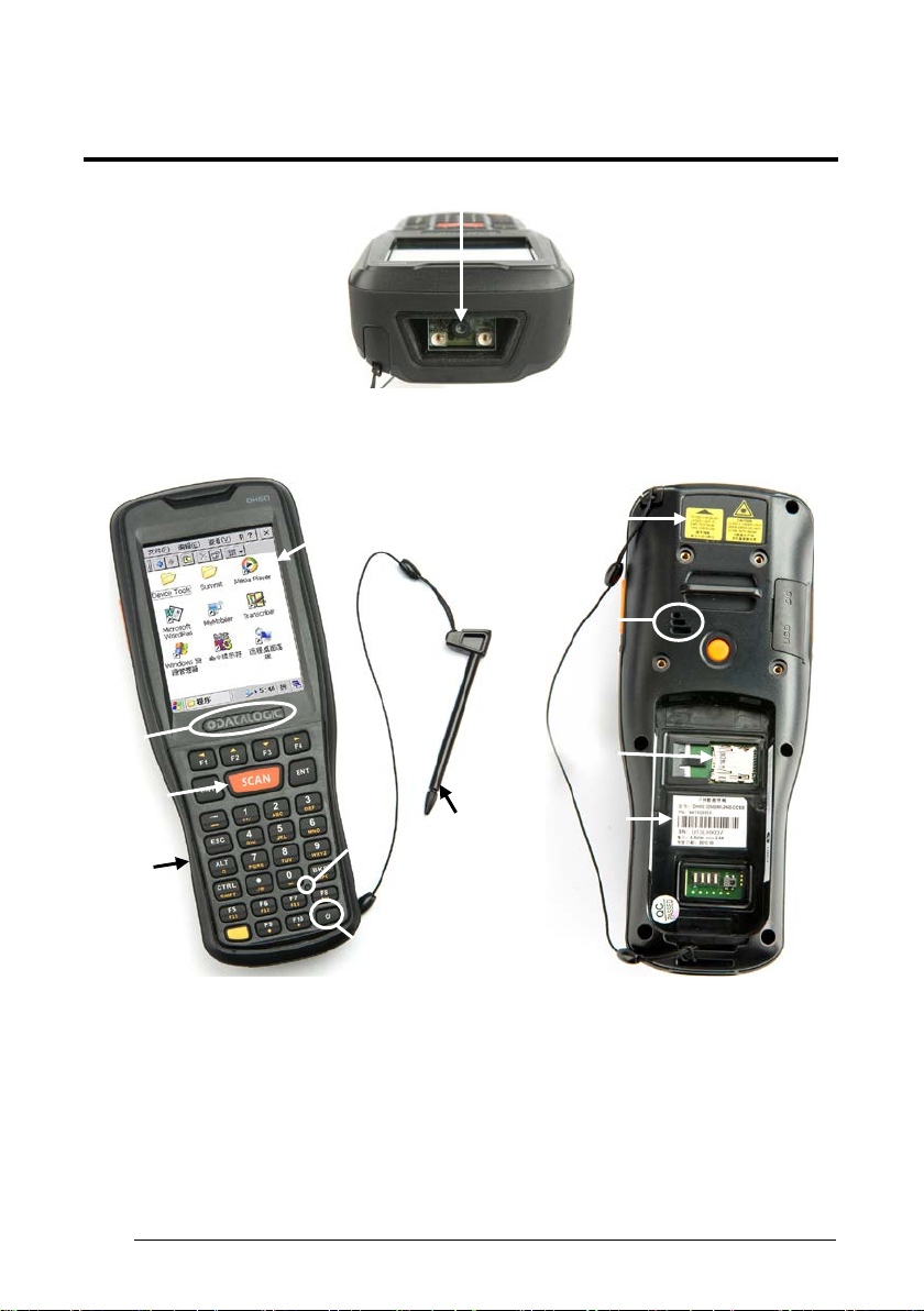
GENERAL VIEW
A
B
C
D
E
F G H
I JK
L
1
A) Data Capture Window
B) Color Display
C) ON/OFF Power Key
D) Status Light
E) Front Scan Key
F) Keyboard
G) Reset key
H) Stylus
I) Laser Safety Label
J) Loudspeaker
K) MicroSD Card Slot (under battery)
L) Product Label (under battery)
Page 7
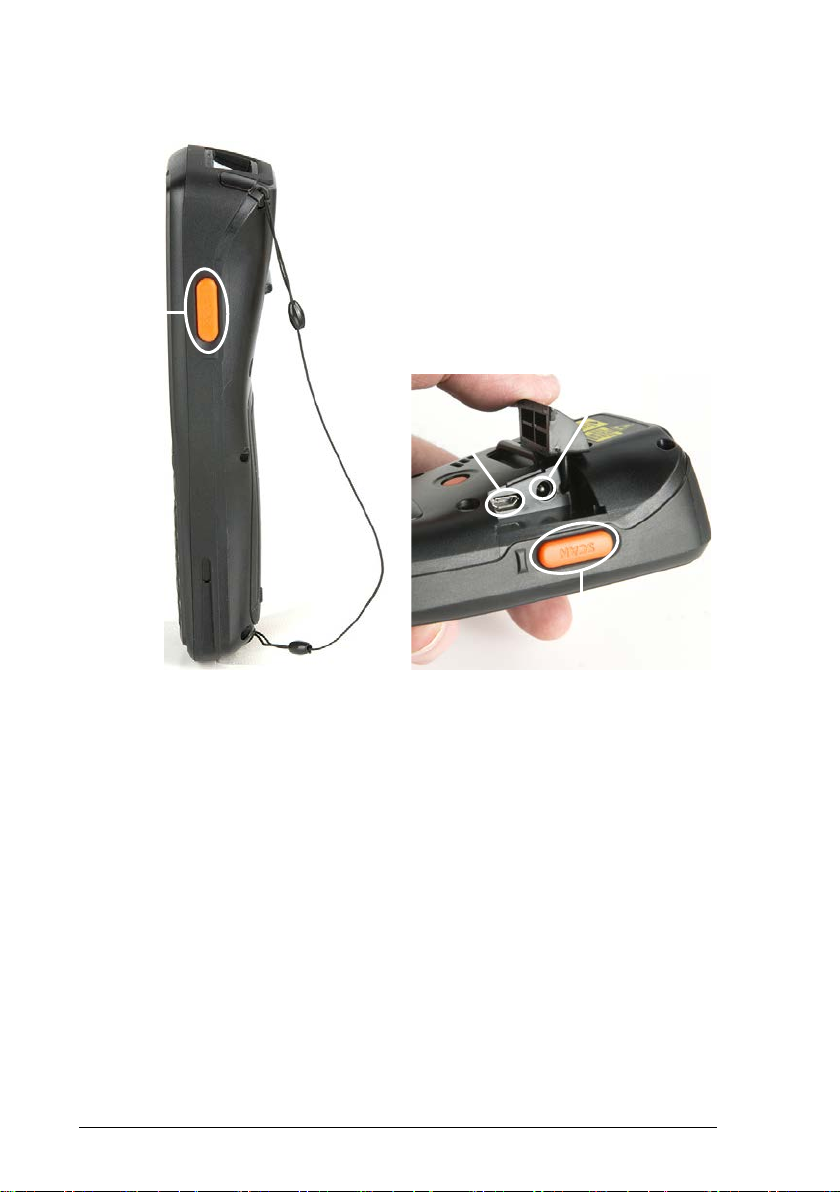
vii
P) Micro USB Port
M N P
O
M) Right Side Scan Key
N) Left Side Scan Key
O) DC Port
Page 8

This page intentionally left blank
1
Page 9

INTRODUCTION
1
1
1 INTRODUCTION
1.1 DH60 DESCRIPTION
The DH60 mobile computer delivers industry leading bar code reading and wireless
communications in a durable and ergonomic form factor. Intended for use in
warehouses, retail stores, and manufacturing facilities, the DH60 mobile computer
tackles a wide variety of inventory management tasks from simple receiving to the
support of material traceability.
State-of-the-art bar code engines supply two options for the DH60 mobile computer:
• A 2D imager option provides a capture device enabled for a wide range of
Linear, Stacked, and 2D bar codes. Camera technology in this scan engine
reduces the number of failed reads due to damaged and poorly printed bar
codes.
• When quickness and accuracy are preferred, the Laser option displays best in
class speed reading the full range of linear symbols and GS1 DataBar™ codes.
All DH60 mobile computer models are coupled with Datalogic’s patented ‘Green
Spot’ technology for good-read feedback. The visual good-read indicator improves
user feedback by projecting a green spot directly on the code just read. For the
warehouse and manufacturing shop floor this Error proofing technology is intuitive
regardless of how noisy the environment is . In quieter retail environments, the ‘Green
Spot’ technology prevents unwanted intrusion on the consumer experience by
enabling silent scanning.
The DH60 mobile computer utilizes a Laird W i-Fi IEEE 802.11 bgn radio with fast
roaming and PCI compliant encryption levels. This powerful combination ensures
real-time inventory transactions that are secure from unwanted snooping.
The DH60 mobile computer withstands the rigors of everyday use. A full shift battery
keeps operators productive throughout the day with fewer battery exchanges
needed. An IP54 sealing rating and 1.5 m / 5 ft drop specification delivers the
durability needed to survive accidental damage and exposure to mois ture and dirt.
These durability ratings contribute to reduced down time for repairs. For additional
investment protection, warranty for this device can be extended through Datalogic’s
EASEOFCARE program that best suits the installations’ requirement.
Datalogic’s software tools and strategic software alliances fit the DH60 mobile
computer for the business practice. Datalogic’s Desktop and Configuration utilities
offer full control over the device experience. Wavelink® Avalanche enables rapid
deployment and central management of the DH60 installation. For facilities with
Page 10

1 DH60
2
1
Warehouse Management Systems (WMS), Wavelink’s Terminal Emulation is
available with all four of the most popular emulation modes.
A full line of mobile computing accessories allow for investment flexibility. Single-slot
docks are available for small s tores while four-slot docks and multi-battery chargers
support the largest of warehouses. A pistol grip handle easily converts the DH60
mobile computer into a gun form factor suitable for scan-intensive receiving and
inventories.
Page 11

INTRODUCTION
3
1
1.2 AVAILABL E MODELS
The DH60 is available in different models depending on the options it is equipped
with. All options are listed below:
• communication options: Laird Wi-Fi IEEE 802.11 bgn, Bluetooth®
• data capt ure options: laser, 2D imager
• operat ing sy ste m: Windows CE 6.0
• keyboard options: numeric.
For further details about the DH60 models refer to the web site:
http://www.datalogic.com
For further information regarding Windows CE refer to the website:
http://www.microsoft.com/windowsembedded
The currently available models are:
• 941100003 DH60 00N0IM-2N0-CCS0
DH60, Handheld, Samsung A8, 256MB/512MB, bgn, Imager, Numeric, CE6
• 941100004 DH60 0000LD-2N0-CCS0
DH60, Handheld, Samsung A8, 256MB/512MB, Batch, P.Laser, Numeric, CE6
• 941100005 DH60 00N0LD-2N0-CCS0
DH60, Handheld, Samsung A8, 256MB/512MB, bgn, P.Laser, Numeric, CE6
.
.
Page 12
1 DH60
4
1
technical assistance center. Damage caused by improper
1.3 PACKAGE CONTENTS
The DH60 package contains:
− 1 DH60 mobile computer
− 1 Power Supply
− 1 Rechargeable Li-ion Polymer battery pack (2600 mAh at 3.7 V - 9.62 Watt-
hours)
− 1 Std-A t o Micro-B USB 2.0 cable (client mode only)
− 1 Quick Start Guide
− 1 End User License Agreement (EULA) Sheet
Any other packages will contain the accessories necessary for the DH60 connection
to the host computer and to the network: the cradle, one or more connection cables.
Remove all the components from their packaging; check their integrity and compare
them with the packing documents.
Keep the original packaging for use when sending products to the
CAUTION
packaging is not covered under the warranty .
Rechargeable battery packs are shipped partially charged. Please
fully charge the battery before use. See sec tion 2.1.
NOTE
Page 13
INTRODUCTION
5
1
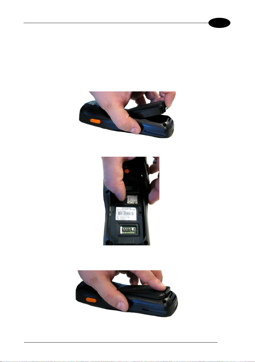
1.4 INSERTING A MICROSD CARD
The DH60 supports microSD memory cards . To access the microSD c ard slot and
insert the card, proceed as follows:
1. Turn off the DH60.
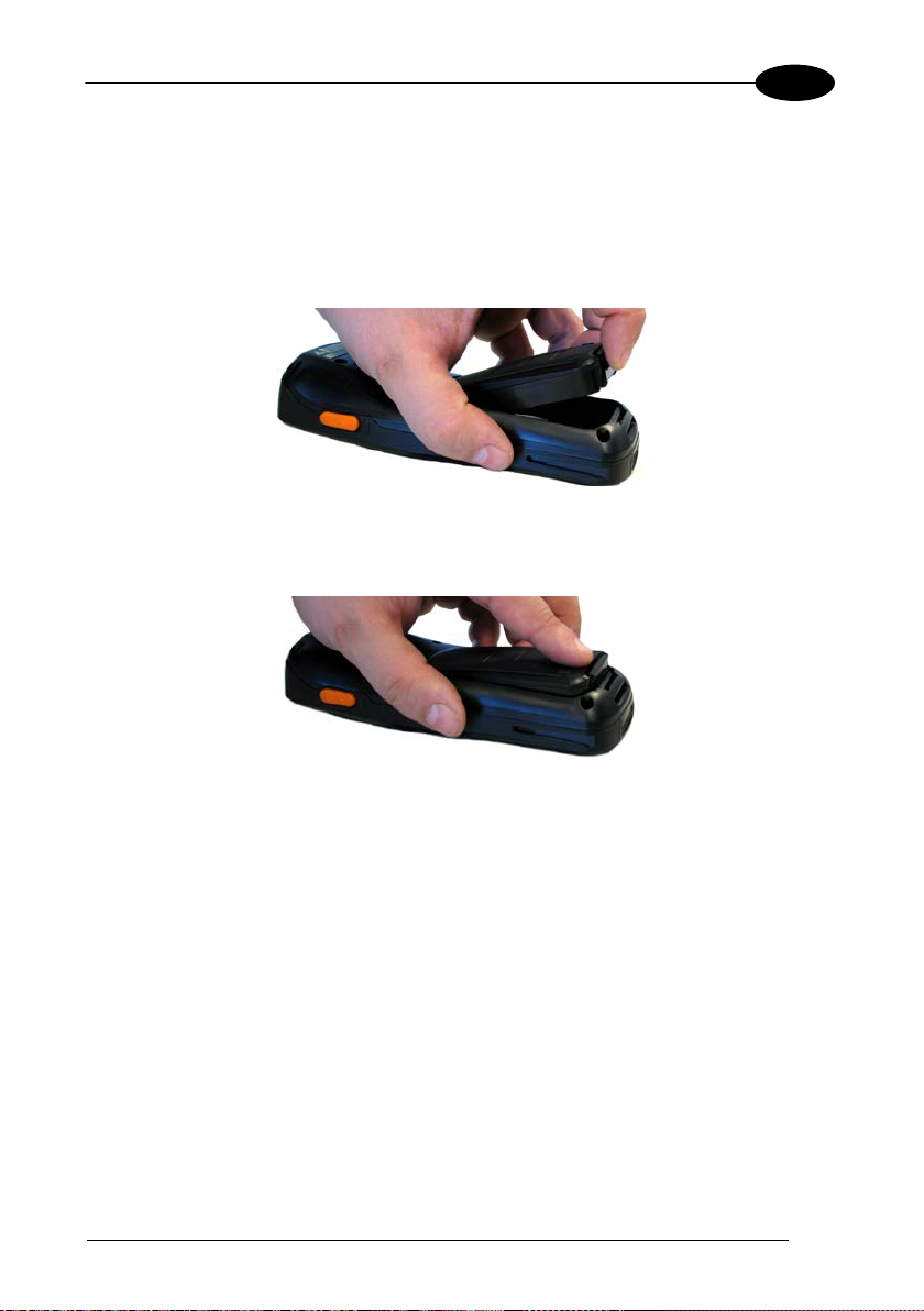
2. Pull the battery latch down and remove the battery pack:
3. Insert the microSD card into the s lot with the gold contacts facing down:
4. Insert the battery's alignment lugs into the recesses, then press firmly until the
battery latch clicks.
Page 14

1 DH60
6
1
ecautions to avoid damaging the
1.4.1 Removing the MicroSD Card
To remove the microSD card, follow the steps above to access the microSD card
cage under the battery, and remove the microSD card from its slot.
Follow proper ESD pr
microprocessors in the DH60 or the microSD card itself.
CAUTION
Proper ESD precautions include, but are not limited to, working on
an ESD mat and ensuring that the operator is properly grounded.
Do not force the card. If you feel resistance, remove the card, check
the orientation, and reinsert it.
Do not use the microSD card slot for any other accessories.
Page 15

INTRODUCTION
7
1
1.5 ACCESSORIES
Cradles
94ACC0086 DH60 single slot desk mount dock with Micro USB
94ACC0088 DH60 multi dock recharges four devices and four batteries (power
supply included)
94ACC0089 DH60 mul ti battery charger recharges four spare batteries (power
supply included)
Batteries
94ACC0085 DH60 battery, 3600 mAh
Power Supply
94ACC0087 Direct and single slot dock power supply
94ACC0090 Multi-slot dock and battery charger power supply
Cables
94A051968 Cable from dock microUSB client to USB
Various
94ACC0091 DH60 handle for conversion to pistol grip (sold separately)
94ACC0092 DH60 holster for belt mounting
Use only a Datalogic approved power supply and cables. Use of an
alternative power supply will invalidate any approval given to this
NOTE
device and may be dangerous.
Page 16
1 DH60
8
2
2 BATTERIES AND MAINTENANCE
Rechargeable backup batteries and battery packs are shipped
partially charged. Please fully charge the device or battery before
NOTE
CAUTION
2.1 CHARGING THE BATTERY PACK
The most direct way to charge a DH60 is to connect the device DC jack to a provided
power supply. Alternatively, the DH60 also be charged by the single slot dock or the
four slot dock.
The battery icon on the Taskbar indicates approximate charge level of the battery
and will indicate a low charge when the DH60 needs to be recharged.
use.
Annual replacement of rechargeable battery pack avoids possible
risks or abnormalities and ensures maximum performance.
The battery pack autonomy varies according to many factors, such
as the frequency of barcode scanning, RF usage, battery life,
NOTE
storage, environmental conditi ons, etc.
Don’t insert the wall charger into the DC port when the DH60 is
inserted into the dock.
CAUTION
Page 17
BATTERIES AND MAIN TENANCE
9
2
The status light glows red when the main battery is recharging. It will glow green
when the battery reaches full charge. The status light will flash red when a charging
error is detected (see par. 4.5.1).
The stand-alone battery pack may be recharged outside a DH60 using the spare
battery charging slot on the back of the single slot dock, the four slot dock, or a four
slot battery charger.
It’s recommended to charge batteries before first use.
NOTE
Risk of explosion if battery is replaced by an incorrect type.
Dispose of used batteries according to the instructions.
CAUTION
Avoid storing batteries for long periods in a state of full charge or very
low charge.
CAUTION
We recommend charging the battery pack every two to three months
to keep its charge at a moderate level to maximize battery life.
The DH60 and spare DH60 batteries should be charged at an ambient
temperature between 10 to 45 °C / 50 to 113 °F to maximize battery
life and run time.
NOTE
Never charge the main device or spare batteries in a closed s pace
where excessive heat can build up.
CAUTION
Page 18
10
2
NOTE
NOTE
1 DH60
The battery level may display incorrectly for several minutes after the
DH60 is disconnected from its charger if the charging cycle is not
completed.
The DH60 may get warm during charging; this is normal and does
not mean a malfunction.
Page 19
BATTERIES AND MAIN TENANCE
11
2
2.2 REPLACING THE BATTERY PAC K
To correctly replace the battery pack, proceed as follows.
1. Turn off th e DH60.
2. Pull the battery latch down and remove the battery pack:
3. Insert the new battery's alignment lugs into the recesses, then press firmly until
the battery latch clicks:
Page 20

12
2
WARNING
Installing, charging and/or any other action should be done by
authorized personnel and following this manual.
The battery pack may get hot, explode, ignite, and/or cause serious
injury if exposed to abusive conditions.
If the battery pack is replaced with an improper type, there is risk of
explosion and/or fire.
Do not place the battery pack in or near a fire or other heat source;
do not place the battery pack in direct sunlight, or use or store the
battery pack inside unventilated areas in hot weather; do not place
the battery pack in microwave ovens, in clothes dryers, in high
pressure containers, on induction cook surfaces or similar devices.
Doing so may cause the battery pack to generate heat, explode or
ignite. Using the battery pack in this manner may also result in a loss
of performance and a shortened life expectancy.
Use only a Datalogic approved power supply. The use of an
alternative power supply will v oid the product warranty, may cause
product damage and may cause heat, an explosion, or fire.
The area in which the units are charged should be clear of debris
and combustible materials or chemica ls.
Do not use the battery pack of this terminal to power devices other
than this mobile computer.
Immediately discontinue use of the battery pack if, while using,
charging or storing the battery pack, the battery pack emits an
unusual smell, feels hot, changes colour or shape, or appears
abnormal in any other way.
Do not short-circuit the battery pack contacts connecting the positive
terminal and negative terminal. This might happen, for example,
when you carry a spare battery pack in your pocket or purse;
accidental short–circuiting can oc cur when a metallic object such as
a coin, clip, or pen causes direct connection of the contacts of the
battery pack (these look like metal strips on the battery pack). Short–
circuiting the terminals may damage the battery pack or the
connecting object.
Do not apply voltages to the battery pack contacts.
Do not pierce the battery pack with nails, strike it with a hammer,
step on it or otherwise subject it to strong impacts, pressures, or
shocks.
1 DH60
Page 21

BATTERIES AND MAIN TENANCE
13
2
Do not disassemble or modify (i.e. bend, crush or deform) the battery
pack. The battery pack contains safety and protection devices,
WARNING
which, if damaged, may cause the battery pack to generate heat,
explode or ignite.
In case of leakage of liquid from the battery, avoid contact with liquid
the skin or eyes. If the contact occurs, immediately wash the affected
area with water and consult a doctor.
Do not solder directly onto the battery pack.
Do not expose the battery pack to liquids.
Avoid any knocks or excessive vibrations. If the device or the battery
is dropped, especially on a hard surface, you should take it to the
nearest Authorised Repair Centre for inspection before continuing to
use it.
Do not replace the battery pack when the device is turned on.
Do not remove or damage the battery pack’s label.
Do not use the battery pack if it is damaged in any part.
Battery pack usage by children should be supervised.
Collect and recycle waste batteries separately from the device in
compliance with European Directive 2006/66/EC, 2011/65,
2002/96/EC and subsequent modifications, with US and China
regulatory laws and regulations about the environment.
Page 22
1 DH60
14
2
In order to maximize operating autonomy, the DH60 checks its
battery level at all times. If the battery is not sufficiently charged,
the DH60 will not turn on when the ON/OFF Power button is
pressed.
NOTE
In this case, either substitute a suffic iently charged battery, insert
the DH60 into a powered cradle, or plug it into a wall c harger.
To maximize battery life, turn off radios when they are not
needed.
NOTE
Page 23

BATTERIES AND MAIN TENANCE
15
2
2.3 CLEANING THE MOBILE COMPUTER
Periodically clean the DH60 with a slightly dampened cloth.
Do not use alcohol, corrosive products or solvents.
Page 24
1 DH60
16
3
A B C
3 CONNECTIONS
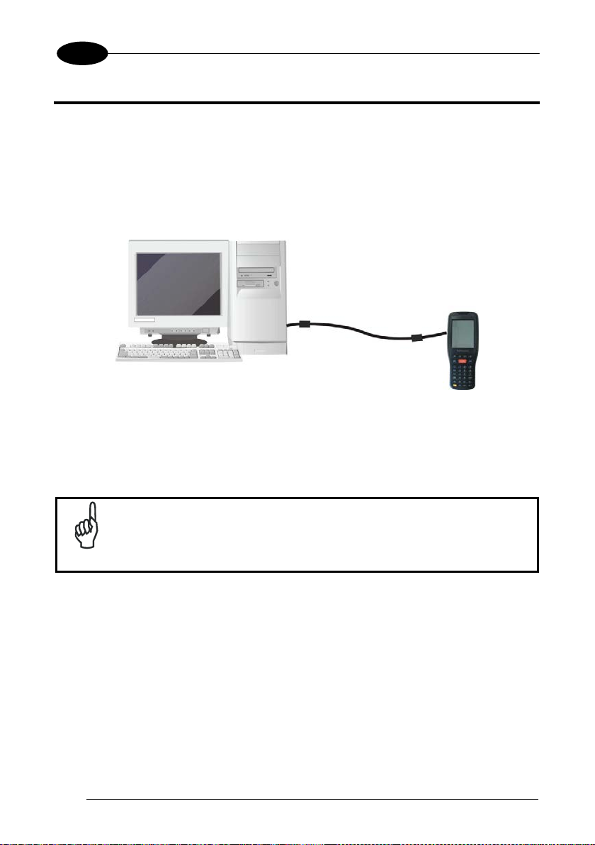
3.1 USB CONNECTION
You can use the standard micro USB cable included in the box to directly connect the
DH60 to a host computer to transfer data through the USB interface.
Key:
A Host computer C DH60
B Std-A to Micro-B USB 2.0 cable
Connection through the cable complies to the USB 2.0 standard.
NOTE
Page 25
CONNECTIONS
17
3
BD C
A
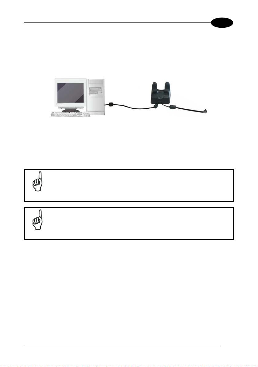
The Single Dock can be connected to the host computer by means of a standard
micro USB cable.
Once the host computer has b een turned on, ins ert the DH60 mobile c omputer i nto
the cradle.
Key:
A Host computer C DH60 Single Slot Dock
B Std-A to Micro-B USB 2.0
D Power Supply
cable
Connection through the cradle complies to USB 2.0 standard.
NOTE
The actual data transfer speed can be appreciably lower than the
maximum theoretical speed.
NOTE
Page 26
1 DH60
18
3
A B C
A
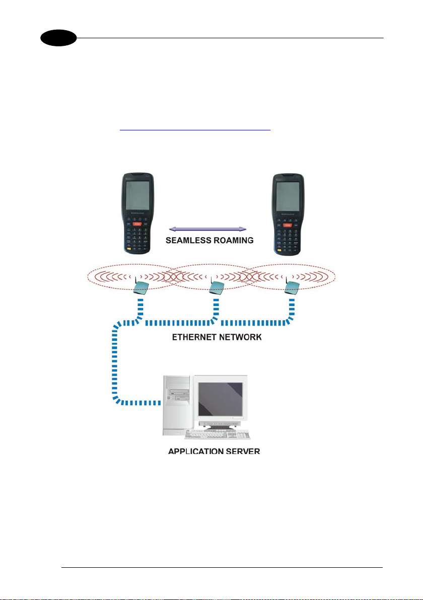
3.2 WLAN CONNECTION
DH60 802.11 bgn radio models can communicate with the host using the on-board
Wi-Fi radio and an Access Point connected to a network.
For models using the 802.11 bgn radio, you can find information about the applet for
radio configuration: http://www.summitdata.com/SCU.htm
To launch this utility you can tap the specific icon if it is visible on the taskbar or you
can select the menu item: Start-> Summit and tap the “SCU” icon.
.
Key:
A) DH60
B) Access poin t
C) Host – Application Server
Page 27
CONNECTIONS
19
3
Area coverage and radio performance may vary, due to
802.11 bgn radio module is on by default. In order to avoid wasting
energy, you can switch it off us i ng the SCU.
NOTE
Suspending the terminal powers off the 802.11 bgn radio and drops
the radio connection. When the terminal resumes, depending on the
radio power mode and security protocol selected, it may take up to
NOTE
30 seconds for the 802.11 bgn radio driver to re-associate the radio
to the network.
environmental conditions, acces s point types or interference caused
NOTE
by other devices (microwave ovens, radio transmitters, etc.).
In case of heavy usage the DH60 may get warm; this is nor mal and
does not mean a malfunction.
NOTE
Page 28

1 DH60
20
3
NOTE
B
3.3 WPAN CONNECTIONS
Datalogic DH60 Bluetooth® models can communicate with a Bluetooth® device,
such as a printer, within a range of 10 m, using the on-board Bluetooth® modu le.
A
Key:
A) DH60
B) Bluetooth® printer
NOTE
NOTE
In order to extend battery life, the Bluetooth® module is off by
default. If you need to have Bluetooth® working, the module must be
enabled through the Bluetooth Manager (see par.4.8.2).
Suspending the terminal powers off the Bluetooth® radio and drops
the piconet (Bluetooth® connection). When the terminal resumes, it
takes approximately 10 seconds for the Bluetooth® radio driver to reinitialize the radio.
Area coverage and Bluetooth® radio performance may vary, due to
environmental conditions or interference caused by other devices
(microwave ovens, radio transmitters, etc.).
Page 29
CONNECTIONS
21
3
Unauthorized antennas, modifications or attachments could
3.4 WIRELESS AND RADIO FREQUENCIES WARNINGS
Use only the supplied or an approved replacement antenna.
damage the product and may violate laws and regulations. The
antennas inside the DH60 are not user-accessible and cannot be
WARNING
WARNING
WARNING
replaced by end users. Send any faulty equipment to Datalogic for
repair.
Most modern electronic equipment is shielded from RF signals.
However, certain electronic equipment may not be shielded against
the RF signals generated by DH60.
Datalogic recommends persons with pacemakers or other medical
devices to follow the same recommendations provided by Health
Industry Manufacturers Associations for mobile phones.
Persons with pacemakers:
• Should ALWAYS keep this dev ice more than twenty five (25) cm
from their pacemaker and/or any other medical device;
• Should not carry this device in a breast pocket;
• Should keep the device at the opposi te side of the pacemaker
and/or any other medical device;
• Should turn this device OFF or move it immediately AWAY if
there is any reason to suspect that interference is taking place.
• Should ALWAYS read pacemaker or any other medical device
guides or should consult the manufacturer of the medical device
to determine if it is adequately shielded from external RF energy.
In case of doubt concerning the use of wireless devices with an
implanted medical device, contact your doctor.
Page 30
22
3
WARNING
WARNING
WARNING
WARNING
1 DH60
Turn this device OFF in health care facilities when any regulations
posted in these areas instruct you to do so. Hospitals or health care
facilities may use equipment that could be sensitive to external RF
energy.
RF signals may affect improperly installed or inadequately shielded
electronic systems in motor vehicles. Check with the manufacturer
or its representative regarding your vehicle. You should also
consult the manufacturer of any equi pment that has been added to
your vehicle.
An air bag inflates with great force. DO NOT place objects,
including either install ed or portable wireless equipment, in the area
over the air bag or in the air bag deployment area. If a vehicle’s
wireless equipment is improperly installed and the air bag inflates,
serious injury could result.
Turn off the device when in any area with a potentially explosive
atmosphere. Observe restrictions and follow closely any laws,
regulations, warnings and best practices on the use of radio
equipment near fuel storage areas or fuel distribution areas,
chemical plants or where any operation involves use of explosive
materials.
Do not store or carry flammable liquids, explosive gases or
materials with the device or its parts or accessories.
Areas with a potentially explosive atmosphere are often, but not
always, clearly marked or shown.
Sparks in such areas could cause an explosion or fire, resulting in
injury or even death.
Page 31

USE AND FUNCTIONING
23
4
Desktop
Control Panel
4 USE AND FUNCTIONING
The use of the DH60 depends on the application software loaded. However there are
several parameters that can be set and utilities that can be used to perform some
basic functions such as data capture, communications, file management, etc
4.1 STARTUP
The DH60 turns on when the battery pack or the external supply is inserted and the
ON/OFF Power button is pressed.
After the battery pack is installed, use the [ON/OFF] key to turn the mobile computer
on and off.
As soon as the mobile computer is on, the Windows CE 6.0 desktop will appear on
the screen. Wait a few seconds before starting any activity so that the mobile
computer completes its startup procedure.
Use the s tylus (par. 4.1.1) as suggested to select icons and option s.
The mobile computer goes into power-off (low power with display and keyboard
backlight off), when it is not used for more than a programmable timeout, which is
defined in the POWER applet of the Control Panel. In this mode it can be awakened
(resuming operation) by the [ON/OFF] key.
Page 32

1 DH60
24
4
Double tap the screen with the stylus to open items and select
Hold the stylus on the screen and drag across the screen to
The mobile computer can also be awakened or suspended
programmatically.
NOTE
4.1.1 Using the Stylus
The stylus selects items and enters information. The stylus functions like a mouse.
Double Tap:
Drag:
options.
select text and images. Drag in a list to select multiple items.
To recalibrate the touch screen use the Stylus applet (see par. 4.6.7).
Use only original Datalogic styluses supplied with the product itself.
In harsh applications, use of screen protectors should be taken into
CAUTION
consideration, in order to extend the touch screen operating life.
To prevent damage to the screen, do not use sharp devices or any
device other than the Datalogic provided stylus.
Do not apply too much pressure when touching the screen.
For applications where an intensive use of the touch screen is
foreseen, please cons ider that touch screen components are subject
to progressive wear.
Page 33

USE AND FUNCTIONING
25
4
4.1.2 Touch Gestures
Touch gestures describe gestures in which you use a finger or stylus to make a
short, directional movem ent over a control or object on the screen. Most gestures are
a single stroke. Windows CE supports five kinds of gestures.
Tap:
Double Tap:
A tap represents the left click of a mouse.
A double tap represents the left double click of a mouse.
Page 34

1 DH60
26
4
4.2 WINDOWS CE TOUCH SCREE N CALIBRAT ION
In Windows CE, at the very first DH60 startup, following a clean boot to restore the
Registry to default values, the mobile computer startup (see par. 4.1) is preceded by
the touch screen calibration screen.
The user must calibrate the touch screen (see par. 4.7.1)
Touch Screen Calibration Screen
Page 35

USE AND FUNCTIONING
27
4
4.3 DATA CAPTURE
To capture data tap Start > Settings > Control Panel > double tap Decoding:
Page 36

1 DH60
28
4
4.3.1 Laser Data Capture
To scan barcodes, point the DH60 laser m odel onto the code from a distance within
the reading range while pressing the SCAN key or the pistol trigger.
The lighted band emitted by the laser must completely cross the barcode as shown in
the figure below.
If the scan has taken place correctly:
− the Good Read LED glows s teadily green for a configurable time;
− if enabled, the
Good Read Beep plays;
− if enabled, the GreenSpot projects a green spot onto the bar code image.
Page 37

USE AND FUNCTIONING
29
4
4.3.2 Imager Data Capture
The DH60 Imager captures a picture of the entire bar code. The omni-directional
scanning does not require that the operator orient the bar code to align with the scan
pattern.
To read a 1D or 2D code, simply point the DH60 Imager model onto the code and
press the SCAN Key or the pistol trigger.
The DH60 Imager uses an intelligent aiming system pattern, similar to those on
cameras, indicating the field of view, whi c h should be positioned over the code:
Aiming System
If the aiming system pattern is c entered over the entire symbology as shown in the
following figure, either wait for the timeout or release the Scan key or the trigger to
capture the image.
Page 38

1 DH60
30
4
Linear barcode
2D Matrix symbol
ÌBX3ÉÎ
A red beam illuminates the code, which is captured and decoded. You will get a good
read.
Relative Size and Location of Aiming System Pattern
The field of view changes its size as you move the reader closer or farther away from
the code. The field of view indicated by the aiming system pattern will be smaller
when the DH60 Imager is closer to the code and larger when it is farther from the
code.
Symbologies with smaller bars or elements (mil size) should be read closer to the
unit. Symbologies with larger bars or elements (mil size) should be read farther from
the unit. (See par. 5.1 for further details).
If the scan has taken place correctly:
− the Good Read LED glows s teadily green for a configurable time;
− if enabled, the Good Read Beep plays.
Page 39

USE AND FUNCTIONING
31
4
4.4 DESCRIPTION OF THE KEYBOARDS
The DH60 comes with a 31 key numeric keyboard defined with two levels of
functionality. Secondary functions are accessed by pressing the yellow button first
and then any key designated as having an alternate symbol.
All the keys can be reprogrammed for unique actions defined by the application, with
the exception of the main Scan key, the power key, and the yellow modifier key.
Page 40

32
4
Main Keys Function
let you move forwards, backwards,
upwards or downwards within text fields, scroll
through a Menu list or browse among folder
When pressed once before a standard
character or function
When pressed twice, it holds the keyboard
in the yellow mode for text entry. A third
press will return the keyboard to the
KEY FUNCTION
1 DH60
The SCAN key starts data captur e.
After a yellow modifier key press, navigation
keys
files.
Yellow modifier (toggle key):
•
key, it enables the
printed in yellow above the key.
•
normal mode.
The ON/OFF Power button powers the DH60
ON or OFF. It is placed on the lower right side
of the terminal.
Page 41

USE AND FUNCTIONING
33
4
Warm Boot
Cold Boot
Clean Boot
Registry
Restored from
flash
Restored from
flash
Clean configuration (no user
config)
File
System
4.4.1 Resetting the DH60
There are several reset methods for the DH60:
• a warm boot terminates an unresponsive application and clears the working
RAM, but preserves the file system. The Registry is restored from persistent
memory if available or returned to factory default;
• a cold boot forces all applications to close, completely rei nit ial izi ng t he s yste m. It
clears the working RAM, but the file system is preserved. The Registry is
restored from persistent m emory;
• a clean boot restores the DH60 to a clean configuration: both the Registry and
the file system returns to a clean status that conforms to factory default.
Warm Boot
To perform a warm boot, press the reset key on the device front (see GENERAL
VIEW).
Cold Boot
To perform a cold boot, press the yellow modifier key and the reset key
Clean Boot
To perform a clean boot, do the following steps:
1. Start menu > Settings > Control Panel
2. Double-tap the RestoreFactorySettings icon.
3. Tap in the field to set the ins ertion point, and then type "1234".
4. Tap the "Restore" button.
5. Follow on-screen prompts to com plete the clean boot.
Preserved Preserved Clean Installation (no user files)
Page 42

34
4
4.5 STATUS INDICATORS
releases the Scan key (or trigger).
(or trigger).
4.5.1 Status Light
The DH60 status light communicates read success and charging status.
STATUS COLOR INDICATES
Light is red from the time the user
presses the Scan key (or trigger) until
When scanning
Green
Red
the bar code is decoded, , until the
scanner times out, or until the user
Light changes to green when a good
decode is completed and t hen r emains
lit until the user releases the Scan key
1 DH60
When charging
Green
Light is solid green once the charging
process has completed (full charge).
Red Light is solid red while charging.
Blinking Red Blinking red indicates a charge fault.
Page 43

USE AND FUNCTIONING
35
4
eSync connection icon is displayed when
connected to ActiveSync or Windows Mobile Device
open a status dialog that will let you disconnect the
ActiveSync session without physically
device from the PC. It is the only
way to disconnect a Bluetooth ActiveSync
tap this
icon to open the Bluetooth Manager control panel
Network connectoid icon displays whether you are
Fi, or Bluetooth
4.5.2 Taskbar
The Taskbar provides quick view and links to the Wi-Fi and Clock settings . It also
makes available the keyboard SIP and window selection.
Windows CE Taskbar
ICONS DESCRIPTION
Activ
Center either by USB or Bluetooth. Double-tap it to
disconnecting the
connection.
Battery icon displays the system battery status.
It indicates that the battery is charging.
Bluetooth Manager icon displays whether Bluetooth
is enabled, paired, or turned off. Doubleapplet.
connected or not to Ethernet, WiPersonal Area Network.
Page 44

1 DH60
36
4
4.6 CONTROL PANEL
From the Start menu, tap Settings then Control Panel. Below is an expanded view of
the Control Panel showing all of the applets.
Windows CE Control Panel
Page 45

USE AND FUNCTIONING
37
4
4.6.1 Data Capture Configuration
From the Windows CE control panel main window, double tap the Decoding icon:
There are two sections in the Decoding control panel, each containing additional
pages. There are seven General Configuration pages and multiple Barcode
symbology pages.
DECODING CONFIGURATION PAGES
Select the desired configuration from the options shown in the figure below, and the
other Decoding Properties figures on the following pages.
Select General,1D Bar Code or 2D Bar Code, then use the menu or tap the left and
right arrow keys to navigate the different pages of the Decoding utility. The menu
options will change to reflect the items most recently selected.
Page 46

1 DH60
38
4
Notification
From the Decoding Properties page, tap Configure > General > Notification. Use it to
set volume, tone, duration, interval and number of various types of beeps.
Good Read
From the Decoding Properties page, tap Configure > General > Good Read. Use it to
enable Good Read indications, the use of Green Spot, the LED or to set the
decoding timeout for dec oding labels.
Page 47

USE AND FUNCTIONING
39
4
Formatting
From the Decoding Properties page, tap Configure > General > Formatting. Use it to
configure prefix, suffix and data separator character strings.
General Options
From the Decoding Properties page, tap Configure > General > General Options.
Select from Label Programming Enable, Symbology IDs and Group Separator
Replacement.
Page 48

1 DH60
40
4
Decoding Options
From the Decoding Properties page, tap Configure > General > Decoding Options.
Use it to configure the User ID for symbologies, Redundancy and Aggressive
Decoding (if supported by the decoding module). Select a symbology to view or
change the available properties settings.
Page 49

USE AND FUNCTIONING
41
4
Devices
From the Decoding Properties page, tap Configure > General > Devices. Use it to
enable or disable the keyboard wedge for Barcode scanner and to enable or disable
Clipboard mode.
Page 50

1 DH60
42
4
1D Barcode Symbology Pages
Use the drop-down menus from Configure > 1D Barcode, or tap the left and right
arrow keys to navigate the different pages of the barcode symbology pages.
Select Configure > 1D Bar Code from the menu to view other configuration options.
Each barcode symbology opens to its own page, as shown in the figure below. Refer
to the sample symbology control panels for examples of the types of fields and
options you can modify.
Page 51

USE AND FUNCTIONING
43
4
Decoding Settings
Select from the Decoding Properties Settings menu to restore previous
configurations and/or other available default settings. Choose from:
• Factory Defaults
• Minimum Settings
• Maxi mum Settings
• Save (New Settings)
• Revert to Saved Settings
The settings are saved when you tap ‘Yes’. To permanently save these settings you
need to save the Registry using the Persistent Registry applet in the Control Panel.
When open, Decoding Properties acts as a simple barcode test tool that provides the
Data decoded and the Data Type of the barcode scanned.
Page 52

1 DH60
44
4
4.6.2 DL Buttons
You can use DL Buttons to associate specific keys, such as <F1>-<F10>, with
specific applicat ions.
From the control panel main window, double tap the DL Buttons icon.
On the DL Buttons tab, customize the program hardware buttons to launch your most
used applications. Under ‘Select a button’, select the button you want to assign a
function to, and then sel ec t a program from ‘Assign a function’.
Page 53

USE AND FUNCTIONING
45
4
down list displays the available function keys
Tap to delete the selected Button. You can only delete
the Buttons you have added. You cannot delete the
“Alt + 6”, “Left Button”, “Pistol
to browse for appli cation files. You can
associate an executable program with the specified
line arguments that are needed for
the specified application. This option is only available
COMMAND DESCRIPTION
Select a Button
New
Delete
Assign a function
Application
Browse
Arguments
This pullto define. Select the desired one from the list.
Select/tap to specify a new Button, not on the “Select a
Button”list.
following buttons:
Trigger”, “Right Button”, “Scan”
This pull-down list displays the available functions.
Displays path to the selected application.
Select/tap
Button
Type the commandwhen “Launch Application” is se lected in the “ Assign a
function” pull-down list.
Page 54

1 DH60
46
4
Adding a new Button
When you select “New” on the “DL Buttons” tab, this opens the “Add Key” dialog box.
To define a new Button, com plete the following steps:
1. Enter the key combination in the “Add Key” textbox.
COMMAND DESCRIPTION
Enter Key Enter the desired key combination in this text box to define a Button.
OK
X
Select/tap OK to add the specified Button.
Select/tap X to cancel adding the specified Button.
Make sure you do not attempt to add a Button that is already defined.
NOTE
2. Select/tap OK to save the new Button. If you select/tap “X”, the key will not be
saved.
Page 55

USE AND FUNCTIONING
47
4
It is possible for the keyboard wedge to activate assigned Buttons
using alphanumeric characters. Barcodes containing characters
associated with assigned Buttons will trigger the action or
application assigned to that Button.
CAUTION
Assigning an action to a charac ter used in a password can render
the DH60 unusable. Please be careful when choosing keys.
CAUTION
Page 56

1 DH60
48
4
4.6.3 Application Switcher
The application switcher provides the same functionality as the standard Windows®
Alt+Tab function. This allows the user to switch between the various open
applications.
The application switcher is activated via an assigned shortcut key specified in the DL
Buttons tab (see par. 4.6.2.) When the assigned button is pressed, the dialog shown
below will be displayed:
Press the assigned button to cycle through the running applications when the dialog
is open. Press <Enter> to switch to the selected application or <Esc> t o close the
application switcher.
Page 57

USE AND FUNCTIONING
49
4
4.7 WIRELESS COMMUNICATIONS
Wireless networking has a customized control, Summit Client Utility (SCU), specific
to the radio. There are two methods to access the SCU.
Start > Programs > Summit > SCU:
Or
From the Control Panel main window, double tap Wi-Fi to open the Summit Client
Utility:
Page 58

50
4
The SCU will open to the “Main” tab:
Summit Client Utility
1. To create a new profile, tap the "Profile" tab:
1 DH60
Information about the wireless network can be entered directly in the profile tab or by
pressing “Scan” when the desired network ESSID is in range.
Page 59

USE AND FUNCTIONING
51
4
2. At the "Scan" screen, select the desired SSID:
3. Click the "Configure" button
4. Follow the on-screen ins tructio ns to setup security parameters for your network.
For more detailed settings specific to your installation please contact your
wireless network administrator .
Page 60

52
4
5. When finished, click “Commit” to save your settings.
1 DH60
Return to the “Main” tab, if you have not previously selected “Commit” you will be
prompted to save your changes.
At the “Main” tab select the profile you jus t created. If you used the “scan” button the
desired profile will have the same name as the ESSID.
Page 61

USE AND FUNCTIONING
53
4
Use the “Status” tab to check connectivity to the network.
More detailed information about the applet for radio configuration can be found at
http://www.summitdata.com/SCU.htm
.
Page 62

1 DH60
54
4
4.7.1 Stylus Calibration
You might need to recalibrate the touch screen (i.e. when you attempt to select one
item with the stylus, another item is erroneously selected).
To recalibrate the touch screen, complete the following steps:
1. From the Control Panel main window, double tap Stylus to open the “Stylus
Properties” applet window:
2. Tap ‘Calibration’ to open the Calibration screen. Tap ‘Recalibrate’:
Page 63

USE AND FUNCTIONING
55
4
3. Carefully press and briefly hold stylus on the center of the target. Repeat as the
target moves around the screen.
4. By completing the calibration procedure you implicitly accept the new calibration
settings.
5. New calibration settings are persistently saved in the Registry.
Startup Stylus Calibration
When starting the terminal, a welcome wizard (with stylus c alibration) comes up if
valid calibration settings are not available. This happens in the following
circumstances:
1. At the first startup of the terminal.
2. After any cold boot if the user skipped stylus calibration earli er .
3. After a Clean Boot.
Page 64

1 DH60
56
4
4.7.2 Volume & Sounds
From the control panel main window, select the Volume & Sounds applet by double
tapping the Volume & Sounds icon:
The Volume & Sounds applet configures audio features of the loudspeaker and
appears as follows:
Page 65

USE AND FUNCTIONING
57
4
4.8 CONNECTING TO OTHER COMPUTERS
There is more than one way to connect the DH60 to a host PC running Windows.
Each requires specific connections in order to funct ion prop erly.
4.8.1 Windows Mobile® Device Center
The desktop application Windows Mobile® Device Center gives you the ability to
synchronize information between a desktop com puter and your DH60.
Synchronization compares the data on the DH60 with that on the desktop
computer and updates both with the most recent information.
Windows Mobile Device Center is only compatible with Windows Vista and Windows
7; if you run Windows XP or earlier, you have to download Microsoft ActiveSync.
You can establish a connection to your DH60 through the following interfaces:
− USB either directly or through the Single Dock
− Bluetooth® (see par. 4.7.2)
To establish a partnership between the DH60 and a host PC, start Windows Mobile®
Device Center and follow the steps below:
1. Connect the DH60 to the host PC. W indows Mobile® Device Center configures
itself and then opens.
2. On the license agreement screen, click Accept.
3. On the Windows Mobile Device Center’s Home screen, click Set up your
device.
4. Select the information types that you want to synchronize, then click Next.
5. Enter a device name and click Set Up.
When you finish the setup wizard, Windows Mobile Device Center synchronizes the
mobile computer automatically .
The DH60 running Windows CE does not come equipped with
Microsoft Office Outlook or any other application that allows users to
view contact, calendar, e-mail, or task data. Users can view files
NOTE
copied to the DH60 by WMDC's file synchronization feature.
Page 66

1 DH60
58
4
NOTE
4.8.2 Bluetooth® Manager Device Setup
Using the DH60 to connect to another device
To create a Bluetooth® pairing between your device and another device that has
Bluetooth® capabilities, ensure that the two devices are turned on, discoverable, and
within close range.
1. From the control panel main window, double tap the Bluetooth Manager icon to
open the Bluetooth Manager control panel. Tap ‘Connections’:
2. Search for available Bluetooth® devices by tapping the button for the type of
device you want (Printer, Serial or All) or tap Discovery > Discover to skip this
step. The DH60 will search for Bluetooth® devices within range.
If you attempt to set up a connection when the Bluetooth® radio is
disabled, you will receive a message reminding you that the radio is
turned off, and asking if you want to turn it on. Tap Yes if you need to
enable the Bluetooth® radio.
Page 67

USE AND FUNCTIONING
59
4
3. Once searching is complete, Bluetooth® device Profiles will be displayed in the
Discovery tab. You can set up a connection to a device in the list by selecting
the device and then tapping the 'Connect' button:
4. To create a pairing, select a service:
5. Configure any encryption, authentication, or virtual port options required by the
service selected.
Page 68

1 DH60
60
4
Icon Service
Dialup Networking
Printer
Object Push (OPP) Object Exchange (OBEX)
ActiveSync
Human Interface Device (HID) - Keyboard
Serial
Personal Area Network (PAN)
Modem
Headset
Handsfree
Virtual Port allows you to specify the incom ing port, which is used to communicate
serially with an incom ing device just as if it were a physical COM port. This option is
available only if you have selected a Printer or Serial service.
Page 69

USE AND FUNCTIONING
61
4
You can also select Encrypt or Authenticate from the Bluetooth® control panel to
apply or modify those settings.
1. To require Authentication, check the checkbox, then tap OK.
2. If required, the Authentication Request dialog will then open, requesting that you
enter a PIN. Use the Input Panel or the keyboard to type the PIN.
3. Tap OK to complete.
The dialog will also appear when an Authentication request is received from another
device.
Page 70

1 DH60
62
4
Once you have set up a pairing, you can view the settings by double-tapping its
name from the Connections tab. Tap the arrow to change the Virtual Port, or Delete
to remove the device pairing. Tap Sync to initiate a Sync (available only if the service
is an ActiveSync connection).
Page 71

USE AND FUNCTIONING
63
4
Using your device to connect to the DH60
Before turning on Bluetooth®, ensure that the two devices are within close range and
that both Bluetooth-enabl ed devices are discoverable.
1. From the Bluetooth Manager control panel, Tap Settings. The Settings tab
allows you to enable or disable the Bluetooth® radio and specify settings for
Incoming Connections.
Page 72

1 DH60
64
4
NOTE
2. Select or clear the “Enable Bluetooth Radio” check box.
If you’re going to be attaching a serial device (i.e. a scanner) to the DH60, us e
the Port control to select a virtual COM port to use for the connection.
5. Tap ‘Find Me’ if you want to make the DH60 discoverable to other Bluetooth®
devices for 60 seconds, allowing them to set up a connection.
By default, Bluetooth® is turned off. If you turn it on, and then turn off
your device, Bluetooth® also turns off. When you turn on your device
again, Bluetooth® turns on automatically.
Page 73

USE AND FUNCTIONING
65
4
4.9 DATALOGIC FIRMW ARE UTILITY
The Datalogic devices are equipped with a field upgradeable firmware mechanism.
Firmware updates are available on the Datalogic website:
http://www.datalogic.com/eng/support-services/automatic-datacapture/downloads/software-utilities-sw-2.html.
After you have downloaded the desired update, there are several ways you can
update the firmware on your device.
− Use Wavelink Avalanche™ if you have multiple Datalogic devices to update.
For more information refer to the dedicated section of the Wavelink website:
http://www.wavelink.com/Datalogic-device-downloads
− If Wavelink Avalanche™ is not available or you have only a few Datalogic
devices to update, use the Datalogic Firmware Utility (DFU), described below,
to install or update the firmware using an ActiveSync connection.
The following sections provide procedures for the retrieval and installation of the
most current firmware image onto a Datalogic device.
.
4.9.1 Retrieving a Firmware Image Update
The following instructions use Internet Explorer to retrieve the most current firmware
image.
1. Launch Internet Explorer on your PC and navigate to the Datalogic website.
2. Navigate to the Downloads section of the website.
3. Using the device selection fields,
click Save to begin copying the files to your local machine (or local network
location).
select the file you want to download, then
Page 74

1 DH60
66
4
NOTE
4.9.2 Installing DFU on the Host PC
Datalogic Firmware Utility (DFU) provides administrators with a field upgrade
mechanism. You must have Microsoft® ActiveSync (for Windows XP devices) or
Windows Mobile® Device Center (for Windows 7 and Vista devices) already loaded
and running on the host PC to use DFU. Refer to par. 4.7.1 for more information
about Windows Mobile® Device Center.
Prior to installing, you must remove any previous versions of DFU
installed on the host PC.
To install the Datalogic Firmware Utility, complete the following steps on the PC:
1. Go to the Datalogic website and download the most current version of the
Datalogic Firmware Utility. Unzip the file, then double-click to run DFU_Setup.
exe.
2. Click OK to conti nue once you have removed previous versions of DFU.
3. The Welcome to DFU Setup Program screen opens.
− Please exit all Windows applications before running this installer.
− Click Next to continue the Setup.
4. Follow the onscreen instructions to complete the installation.
Page 75

USE AND FUNCTIONING
67
4
NOTE
4.9.3 Updating the Firmware
After copying the firmware image to the host PC (see par. 4.10.1) and installing DFU
(see par. 4.8.2), you can upgrade the firmware on your Datalogic device.
The following steps require that you have already established an
ActiveSync or Windows Mobile Device Center connection between
the host computer and the Datalogic device.
1. Go to Start > Programs > Dat alogic > DFU > Datalogic Firmware Utility.
2. Verify that ActiveSync is selected by clicking Communications >
ActiveSync.
3. Click browse (...) and navigate to the location where you saved the firmware
file for your terminal.
WMDC/
4. Select the current *.out file and click Open.
5. Click Update.
6. DFU will compare the selected firmware image with the firmware already
loaded on the device; if the image is compatible with the connected device,
DFU will proceed to update the firmware image on your device.
After the firmware of your device has been updated, DFU will automatically
perform a warm reset of the device.
Page 76

1 DH60
68
4
4.10 DATALOGIC CONFIGURATION UTILITY
Datalogic Configuration Utility (DCU) is a Datalogic Windows-based utility tool
allowing the uploading, modifying and downloading of the configuration of a Datalogic
device. Configuration settings include Scanner, Control Panel, and Datalogic
Desktop Utility (DDU). The DCU installer is downloadable from the Datalogic website
http://www.datalogic.com/eng/support-services/automatic-data-
(
capture/downloads/software-utilities-sw-2.html).
DCU functions in both direct (with an ActiveSync connection) and indirect (with
Wavelink Avalanche™) modes.
In direct mode, connect a device through ActiveSync and then click on the Get from
Device icon to receive the device’s current conf ig urati on.
Once loaded, the Configuration Tree (on the left side of the window) is used to
navigate the device’s configuration. The right side of the window is a work area
where the values of different parameters may be set for each branch of the
configuration tree. Click on the parameter group branch to open it and inspect the
parameters you wish to modify.
After altering the device’s configuration, the new configuration can be sent to the
terminal by clicking on the Send to Device icon.
Reference the Wavelink Avalanche™ documentation on the Wavelink website
(www.wavelink.com/Datalogic-device-downloads
for DCU, which will allow you to update the configuration of multiple devices
simultaneously over Wi-Fi.
) for a description of indirect mode
Page 77

USE AND FUNCTIONING
69
4
NOTE
4.11 DATALOGIC DESKTOP UTILITY
Datalogic Desktop Utility (DDU) allows administrators to configure Windows
Embedded Handheld devices to control individual user access. This includes the
ability to:
®
CE and
• Prevent users from changing your device OS settings.
• Use Application Selector to replace the desktop with a selec tion of authorized
applications.
• Restrict user access in Internet Explorer.
• Set up configuration and customized error recovery mechanisms.
• Create quick access hot keys and configure trigger actions.
To open DDU for the first time, tap Start > Settings > Control Panel > or Start >
Programs > Device tools > and then double tap the icon for “Datalogic Desktop
Utility”.
You can also open DDU by pressing the appropriate key shortcut. The default is “Alt
+ 6”.
The key combination can be changed by using DL Buttons to redefine
the association for specific k eys (s uch as <F1>-<F10>). See par. 4.6.2
for more information.
Page 78

70
4
4.11.1 Administrative Options (Admin tab)
such as Windows Access Restrictions and Application
Selector.
Enter a password in the text box. This allows the user to
specify a password when this utility is launched. By
default the password is “1234”. A password can consist
of all standard keyboard c haracters.
To change or remove the password, enter a new value,
re-enter the new value, and select/tap “Set Password”.
to reset the default values of
all the functions on all the tabs. After you select this
When you open the DDU control panel, the “Admin” tab appears.
1 DH60
COMMAND DESCRIPTION
Enable Datalogic Desktop Select/tap this checkbox to activate the DDU functions
Enter Password
Re-Enter Password Carefully re-enter the password in the second text box.
Set Password Select/tap “Set Password” to enable the password.
Set Defaults Select/tap “Set Defaults”
option, you will receive a prompt to verify this selection.
Page 79

USE AND FUNCTIONING
71
4
Setting a Password
To set a password:
1. Enter a password in the field. This allows the user to specify a password when
this utility is launched. By default the password is “1234”.
Be sure to record the Pass word for future reference.
NOTE
2. Re-enter the password in the second field.
3. Select/tap “Set Password” to enable the password.
4. Select/tap “OK” to close the “Set Password Confirmation” dialog.
You must select/tap “Set Password” prior to exiting DDU in order to
store and activate your new password. It is not necessary to select
NOTE
“Enable Datalogic Desktop”.
If you select/tap “Set Defaults” it will remove all custom settings and
restore all the factory default settings, except a previously set
password.
CAUTION
Changing a Password
To change to a new password:
1. Enter a new value in the “Enter Password field”.
2. Re-enter the new value in the “Re-enter Password” field.
3. Select/tap “Set Password”.
Page 80

1 DH60
72
4
Removing a Password
To remove a password:
1. Delete all characters from both “Password” fields.
2. Select/tap “Set Password”.
Password Request Dialog Box
Once the password is set, the next time you open the “Datalog ic Des kt op Ut il it y”, the
DDU Password dialog box opens.
This dialog box will only open if a password was defined.
1. Type in your password using either the keypad on the unit, or using the stylus on
the soft input panel (SIP).
If you enter an incorrect password, the system will prompt you to input the
correct one.
2. Select/tap “OK” to verify the password. Or tap “X” to cancel.
Page 81

USE AND FUNCTIONING
73
4
4.11.2 Windows Controls
Select/tap the “W in” (Windows Controls) tab to access the W indows Controls option.
Use Windows controls to allow or restrict access to Windows system functions.
You can disable normal W indows functions such as the taskbar, leaving nothing but
a blank workspace. This allows applications to be run in full screen mode and
prevents users from accidental or unauthorized use of the taskbar, Internet Explorer,
and any other resident applications.
Page 82

1 DH60
74
4
present.
Enabled
desktop icons are accessible or not
WINDOWS CONTROLS
Show Taskbar Select/tap “Show Taskbar” to specify whether the
Taskbar is displayed or not
Taskbar Enabled Select/tap “Taskbar Enabled” to specify whether the
taskbar is accessible. This option is only available
when the “Show Taskbar” is checked.
AutoSIP Enabled Enables the AutoSIP Windows feature.
Scroll Bars Enabled
Windows CE Desktop
Changes require a device reboot.
NOTE
This control only takes effect in Locked Web Browser.
When checked, displays horizontal and vertical scroll
bars to help view large web pages which do not fit the
screen. When unchecked, scroll bars will not be
Windows CE Desktop Enabled specifies whether the
Page 83

USE AND FUNCTIONING
75
4
4.12 AUTOSTART
The AutoStart program provides three functions:
- Allows you to create a list of applications (with optional command line
arguments) to run automatically prior to loading CAB fi les.
- Automatically reinstalls specified CAB files when the DH60 i s cold booted.
- Allows you to create a list of applications (with optional command line
arguments) to run automatically after loading CAB files.
AutoStart launches each time the DH60 is rebooted executing each line with the
specified command line arguments. It will take into account any AutoStart options at
the beginning of the line.
Upon a Cold Boot, AutoStart installs all the CAB files located in the \CAB folder. If the
CAB folder does not exist, no CAB files will be installed.
AutoStart will then run the
Autostart.ini from the \ root directory, executing
each line with the specified com mand line arguments. It will take into account any
AutoStart options at the beginning of the line.
4.12.1 Installing CAB Files
Copy any CAB files you want to install into the \CAB folder. These CAB files will then
be automatically installed in alphabetical order the next time you start the device.
Page 84

76
4
4.12.2 How AutoStart Uses Wceload
Specifies that you will not be prompted for any input during the
be answered ‘Yes.’ If the CAB is unsigned, then any responses wil l
If you intend to create highly interactive installers, you should either
install the CABs manually or review the section on “Interactive CAB
NOTE
CAUTION
CAB files are installed by AutoStart using the
following table shows available command line option:
Option Description
Install” in this chapter..
In certain environments, CAB files will be deleted after execution.
To prevent the CAB file from being deleted, write protect the file
before copying the file onto the device.
Wceload.exe application. The
1 DH60
/noui
/silent Suppresses dialog boxes during the installation.
Please refer to the Microsoft documentation on your device for further details on
installation. If the CAB file is signed, any responses will automatically
be answered ‘No.’
Wceload.exe.
Sample:
\Windows\Wceload.exe /delete 1 /noui /silent
“\CAB\<cab file>”
Page 85

USE AND FUNCTIONING
77
4
4.12.3 Interactive CAB Install
− If the CAB installer requires user interaction that must be performed during the
AutoStart CAB installation process, you can specify a special file name to disable
the silent mode installation. If this mode is specified, the CAB file will be installed
with Wceload without any command line arguments specified.
An example of what AutoStart would execute is:
\Windows\Wceload.exe <cab file>
To force this mode of installation via AutoStart, rename the CAB file to include a ‘_’
character before the “.cab” extension of the file.
Example:
“File.cab” should be renamed “File_.cab” to force AutoStart to not
install the CAB in silent mode. This specially-named CAB file should be placed in the
AutoStart folder with other CAB files intended for installation on the next reboot.
4.12.4 Autostart.ini
A file named ‘PreAuto.ini’ can also be created in addition to or
instead of Autostart.ini. PreAuto.ini is executed before CAB files in
the \Cab folder are installed. Autostart.ini is executed after CAB files
NOTE
Autostart.ini is a text file that AutoStart will run upon startup of the DH60, and after
any CAB files are installed. This file should be placed in the \root folder. AutoStart will
run the Autostart.ini file on each reboot of the device.
in the \Cab folder are installed. The format for the PreAuto.ini is
identical to that of Autostart.ini..”
Line Formatting
Each line of the
executable, and any comm and line arguments.
Autostart.ini can consist of Autostart options, an
< Autostart option(s)> <full path to executable>
<command line arguments>
Sample:
- \windows\pword.exe \file.doc
Page 86

1 DH60
78
4
The following table breaks down the sample Autostart.ini line:
Autostart option(s) Full path to executable Command line arguments
- \windows\pword.exe \file.doc
Spaces must be placed between each component of the line in the Autostart.ini.
If the executable path is in a folder that contains spaces in the name, quotes are
required to distinguish what the actual executable name is. The following is an
example of this:
“\Program Files\ScannerApp.exe” /run
(valid)
\Program Files\ScannerApp.exe /run
(invalid)
The second line is an invalid line because there is no way to distinguish the
executable from the argument.
Page 87

USE AND FUNCTIONING
79
4
Comment: This line will not be
This may only be used as the
first character of the line. If the
comment option is specified in
ons elsewhere, it is
This will cause the line to
execute and immediately move
Query: Request user
firmation when running the
This will halt parsing the
til the
tion is answered. This
tended for debugging the
Autostart.ini file.
AutoStart Options
The table below shows options you can use when writing a line in the Autostart.ini
file.
Description Character Comments
executed.
‘#’ OR ‘ ‘ (space)
the opti
ignored.
Do not wait on line completion:
‘-’
onto the next line.
Autostart.ini un
con
executable.
‘?’
confirma
is in
Execute only on Cold Reset ‘!’
Execute only after a warm boot %
Cold Reset Only: This will cause the line to execute only after a Cold Reset.
An empty line will be treated as a comment line.
NOTE
Page 88

1 DH60
80
4
Combining Options
Autostart options can be combined together as show n in the follow ing sam ple :
?- \Windows\Pword.exe
This line would:
− Request confirmation before executing the line. The next line would not be
processed before the confirmation is answered.
− Run the next line without waiting on the current line to complete execution.
Query Option
The query option is intended for use when debugging the autostart.ini. When a line
with this option is executed, the following dialog will appear with the specified
executable and command line arguments. The populated fields shown in the
AutoStart Execute Query are described the next table:
Field Description
Line Number This is the line number in the script being executed.
Exe The executable as parsed by AutoStart.
Args The argument as parsed by AutoStart.
Page 89

USE AND FUNCTIONING
81
4
The current line will not execute and AutoStart will
The fields may be broken up into multiple lines (as shown in the
example) due to limited space in the dialog.
NOTE
AutoStart Query Options
Parentheses are used to surround the given field and make it very clear what the
value of the field is.
The following table describes the results of each choice:
Button Action
Yes The current line will execute.
No
Cancel
The current line will not execute. AutoStart will continue
parsing the Autostart.ini.
discontinue parsing the Autostart.ini.
Page 90

82
4
Autostart.ini Samples
My
This will confirm the execution of
cified argument
“\My Documents\Sample.cab”
Program with the
Program with the
Program
This will confirm the execution of
cution is confirmed,
AutoStart will immediatel y process the next line.
This will execute the program \Program
App.exe with the argument /run ONLY after a
Cold Reset.
The next table is a collection of sample Autostart.ini lines:
Line Description
1 DH60
? \windows\wceload.exe “\
Documents\Sample.cab”
\Program Files\App.exe
\Program Files\App.exe /run
“\Program Files\App.exe” /run
?- \Windows\Pword.exe
!”\Program Files\App.exe” /run
\Windows\wceload.exe with spe
(invalid) This will execute \
argument Files\App.exe.
(invalid) This will execute \
argument Files\App.exe /run.
This will execute the program \
Files\App.exe with the argument /run.
\Windows\Pword.exe. If the exe
Files\
Page 91

TECHNICAL FEATURES
83
5
Hand held: 185x 73 x 38 mm, 58 x 30 mm at
With handle: 185 x 73 x 190 mm
Green or Red lamp to indicate Decoding or
Withstands 18 drops from 1.5 m / 5.0 ft onto a
PARTICULATE AND WATER
SEALING
Air: ±8kV
Indirect: ±8kV coupling
5 TECHNICAL FEATURES
5.1 TECHNICAL D ATA
PHYSICAL CHARACTERISTICS
DIMENSIONS (LxWxH)
WEIGHT
keyboard
Hand held: 340 g (12 oz)
With han dle: 438 g (15.5 oz)
AUDIO Beeper
STATUS LIGHT
Charging status
Transflective TFT daylight readable color display,
DISPLAY
240 x 320 pixels, 3.2 inch diagonal, 64 K colors,
200 nit backlight, touch screen
KEYBOARD
31 key numeric with ten functional keys and two
side scan keys
OPERATING TEMPERATURE* -10 to 50 °C / 14 to 122 °F
CHARGING TEMPERATURE** 10 to 45 °C / 50 to 113 °F
STORAGE TEMPERATURE -20 to 70 °C / -4 to 158 °F
HUMIDITY*** 5 - 95% non condensing
DROP RESISTANCE****
concrete surface
IP54
ELECTROSTATIC DISCHARGE
(ESD)
* Close to the limits of the working temperature, some display and/or battery performance
degradation may occur.
** Never charge the main device or spare batteries in a closed space where excessive heat
can build up.
*** Multiple rapid humidity and/or temperature variations may cause condensing.
**** Multiple drops can permanently damage the device.
Direct: ±4kV contact
Page 92

84
5
WIRELESS LOCAL AREA
SYSTEM
OPERATING SYSTEM Microsoft Windows CE 6.0 Core
MICROPROCESSOR Samsung A8 S5PV210 clocked at 800MHZ
SYSTEM RAM MEMORY 256 MB
SYSTEM FLASH MEMORY 512 MB
EXPANSION MicroSD card slot up to 32 GB capacity
1 DH60
POWER*
Single piece rechargeable Li-ion Polymer battery
pack 2600 mAh at 3.7V (9.6 Watt-hours)
CLOCK Real-time clock
COMMUNICATIONS
WIRED INTERFACES Micro USB
NETWORKING (WLAN)
WIRELESS PERSONAL AREA
NETWORKING (WPAN)
* Use only DL approved battery packs, power adapters, and charging accessories.
Laird IEEE 802.11 b/g/n
Bluetooth® Wireless Technology with EDR, IEEE
802.15 v2.1
Page 93

TECHNICAL FEATURES
85
5
128, Codabar, EAN/UPC, GS1 DataBar,
128, Codabar, EAN/UPC, GS1 DataBar,
Interleaved 2/5, Matrix 2/5, MSI, Standard /25,
QR Code, GS1
GS1 DataBar Stacked, GS1 DataBar Stacked
Omnidirectional, GS1 DataBar Expanded Stacked
IEC/EN60825-1 Class 1 LED;
IEC/EN62471 Class 1 LED
READING OPTIONS
LASER CHARACTERISTICS
SCANNING RATE 100 ± 10 scans/sec
MINI MUM RESOLUTIO N 0.10 mm / 4.0 mils
DEPTH OF FIELD
5.0 to 64.0 cm (2.0 to 25.0 in), depending on bar
code size and density
China Post, Code 32, Code 39, Code 93, Code
BAR CODES
Interleaved 2/5, MSI, Standard 2/5, Trioptic
LASER CLASSIFICATION EN60825-1 Class 2, CDHR Class II
IMAGER CHARACTERISTICS
SCANNING RATE 60 frames/sec maxi mum
MINI MUM RESOLUTION Linear codes at 4 mils; 2D codes at 5 mils
DEPTH OF FIELD
4 to 40 cm (1.6 to 15.5 in), depending on bar code
size and density
1 D Codes:
China Post, Code 32, Code 39, Code 93, Code
Trioptic
2D Codes:
Aztec Code, Data Matrix, Maxicode, Micro QR
Code, MicroPDF417, PDF417,
BAR CODES
DataBar™ Composites, UPC/EAN Composites
Postal Codes:
Australian Post, China Post, USPS Intelligent Mail,
Japanese Post, KIX Post, USPS PLANET, USPS
POSTNET, UK Royal Mail
Stacked Codes:
LASER CLASSIFICATION EN60825-1 Class 2, CDHR Class II
LED CLASSIFICATION
Page 94

1 DH60
86
5
Guaranteed Reading Diagram – measured from the device nose (10° skew angle)
100
200
300
400
0
200
100
300
400
mm
0,13 mm
(5 mils)
0,19 mm
(7,5 mils)
1,4 mm
(55 mils)
0,25 mm
(10 mils
)
0,33 mm
(13 mils
)
0,50 mm
(20 mils)
1,00 mm
(40 mils)
0
100
300
200
400
500
600
700
800
900
mm
0,38 mm
(15 mils)
5.2 READING DIAGRAMS
DH60 Performance Laser (SE955)
Page 95

TECHNICAL FEATURES
87
5
Guaranteed Reading Diagram – Measured from the device nose (10° skew angle)
50
100
150
200
0
100
50
150
200
mm
0
50
150
100
200
250
300
350
400
450
500
mm
5.0 mil
PDF417
6.67 mil
PDF417
7.5 mil
Code 39
10 mil
PDF417
13 mil
UPC-A
15 mil
PDF417
5.0 mil
Code 39
20 mil
Code 39
DH60 Area Imager (SE4500)
Page 96

88
6
6 TEST CODES
0.25 mm (10 mils)
ÌtestwÎ
80%
1 DH60
High Density Codes
Code 39
17162
2/5 Interleaved
Code 128
EAN 13
0123456784
test
x(0B2DE5*KKKKLM(
EAN 8
80%
(6450*TRMN(
Page 97

TEST CODES
89
6
0.38 mm (15 mils)
0123456784
ÌtestwÎ
100%
Code 39
Interleaved 2/5
Code 128
Medium Density Codes
17162
test
100%
EAN 13
EAN 8
x(0B2DE5*KKKKLM(
(6450*TRMN(
Page 98

1 DH60
90
6
0.50 mm (20 mils)
0123456784
ÌtestwÎ
120%
Code 39
Interleaved 2/5
Code 128
Low Density Codes
17162
test
120%
EAN 13
EAN 8
x(0B2DE5*KKKKLM(
(6450*TRMN(
Page 99

TEST CODES
91
6
Example
2D Codes
Datamatrix ECC200
Inverse
Datamatrix ECC200
Example
Page 100

92
REGULATORY INFORMATION
Read this manual carefully before performing any type of connection
to the DH60 mobile computer.
NOTE
GENERAL SAFETY RULES
− Use only the components supplied by the manufacturer for the specific
DH60 being used.
− Do not attempt to disassemble the DH60 mobile computer, as it does not contain
parts that can be repaired by the user. Any tampering will invalidate the
warranty.
− When replacing the battery pack or at the end of the operative life of the
DH60 mobi le c ompu te r, disposal must be performed in compl iance with the laws
in force in your jurisdiction.
− Before using the devices and the battery packs, read chap. 2.
− Do not submerge the DH60 in liquid products.
The user is responsible for any damage caused by incorrect use of
the equipment or by inobservance of the indication supplied in this
manual.
− For further information, refer to this manual and to the Datalogic web site:
www.datalogic.com
.
POWER SUPPLY
This device is intended to be supplied by a self-contained rechargeable lithium-ion
battery pack (SELV, LPS) and/or by UL Listed/CSA Certified Power Unit marked
“Class 2” or LPS power source which supplies power directly to the unit via the power
connector of the cable.
 Loading...