

Datalogic H2N0LD-1Q1-MEN0, H2N0LD-1N1-MEN0, 00N0WI-1Q1-MEN0, H2N0WI-1Q1-MEN0, H2N0WI-1N1-MEN0 User Manual
...Page 1

1 INTRODUCTION
1.1 LYNX DESCRIPTION
The Lynx contains the most innovative technical features, providing them to the user
in an ergonomic and elegant form factor. The accelerometer, the vibrator alert and
the 3 LEDs help to do not waste time in the configuration and us age of the product.
Working with the Lynx becomes an easy pleasure.
The great aesthetics does not put the rubustness on a second level.T he Lynx has
been deisgned for surviving to industrial environmental, outside and inside the four
walls. The reliability of the product continues with the architecture chosen: an
806MHz processor working with 256 MB RAM and 512 MB of Flash. A Micro SD card
slot supporting SDHC storage cards provides for virtually unlimited storage space.
The Lynx has been equipped with both a 1D laser scanner and 2D bar code imager.
For being ready also to the most demanding applicatinons, an autofocus camera with
flash has been foreseen on the back of the product.
The Lynx provides four wireless technologies in the same form factor, without
antenna protruding: Bluetooth® v2.1 EDR for fast data transfer, 802.11b/g/n with
CCX v4, 802.11i Security, UMTS HSPA+ for real-time communication outside the
four walls and Assisted GPS (A-GPS) with Skyhook‘s Core Engine hybrid positioning
system for location based applications.
Them micro-USB port facilitates charging with a phone industry standard power
supply or On-the-Go (OTG) communications.
The Lynx integrates the latest Windows Embedded Hend Held 6.5, tailored for mobile
devices.
As all the Datalogic ADC Computers, also this PDA is offering Wavelink Avalanche®
for a fast configuration and deploymant.
Finally, Datalogic’s comprehensive service programs protect the Lynx investment.
Page 2

1.2 AVAILABLE MODELS
The brand new Lynx is available in different models depending on the optio ns it is
equipped with. All options are listed below:
communication options: 802.11 b/g/n radio, Bluetooth®, GSM
data capture options: laser, 2D imager
compute options: Windows Mobile 6.5
keyboard options: numeric, qwerty
For further details about the Lynx models refer to the web site:
www.adc.datalogic.com
.
For further information regarding Windows Embedded Handheld refer to the website:
http://www.microsoft.com/windowsembedded
.
The currently available models are:
944400000 Lynx 00N0LD-1N0-MEN0
Lynx with Bluetooth v2.0, Wi-Fi 802.11 b/g/n, Decodified Laser (SE955),
Windows Mobile 6.5, 27-Key Numeric
944400001 Lynx H2N0LD-1N1-MEN0
Lynx with Bluetooth v2.0, UMTS HSPA+ Voice and Data, Assisted GPS, Wi-Fi
802.11 b/g/n, Decodified Laser (SE955), Camera, Windows Mobile 6.5, 27-Key
Numeric
944400002 Lynx 00N0WI-1N1-MEN0
Lynx with Bluetooth v2.0, Wi-Fi 802.11 b/g/n, 2D Imager (4500) Wide Aspect,
Camera, Windows Mobile 6.5, 27-Key Numeric
944400003 Lynx H2N0WI-1N1-MEN0
Lynx with Bluetooth v2.0, UMTS HSPA+ Voice and Data, Assisted GPS, Wi-Fi
802.11 b/g/n, 2D Imager (4500) Wide Aspect, Camera, Windows Mobile 6.5, 27Key Numeric
944400004 Lynx 00N0LD-1Q0-MEN0
Lynx with Bluetooth v2.0, Wi-Fi 802.11 b/g/n, Decodified Laser (SE955),
Windows Mobile 6.5, 46-Key QWERTY
944400005 Lynx H2N0LD-1Q1-MEN0
Page 3

Lynx with Bluetooth v2.0, UMTS HSPA+ Voice and Data, Assisted GPS, Wi-Fi
802.11 b/g/n, Decodified Laser (SE955), Camera, Windows Mobile 6.5, 46-Key
QWERTY
944400006 Lynx 00N0WI-1Q1-MEN0
Lynx with Bluetooth v2.0, Wi-Fi 802.11 b/g/n, 2D Imager (4500) Wide Aspect,
Camera, Windows Mobile 6.5, 46-Key QWERTY
944400007 Lynx H2N0WI-1Q1-MEN0
Lynx with Bluetooth v2.0, UMTS HSPA+ Voice and Data, Assisted GPS, Wi-Fi
802.11 b/g/n, 2D Imager (4500) Wide Aspect, Camera, Windows Mobile 6.5, 46Key QWERTY
Page 4

1.3 PACKAGE CONTENTS
The Lynx package contains:
1 Lynx PDA
1 Lynx quick start guide
1 rechargeable battery pack (standard for Wi-Fi models, high cap for UMTS
models)
1 power supply with regional plugs
1 Lanyard
1 guitar pick stylus
Any other packages will contain the accessories necessary for the Lynx connection
to the host computer and to the network: the cradle, one or more connection cables.
Remove all the components from their packaging; check their integrity and con gruity
with the packing documents.
Keep the original packaging for use when sending products to the
technical assistance center. Damage caused by improper
packaging is not covered under the warranty.
CAUTION
Page 5

Rechargeable battery packs are not initially charged. Therefore the
first operation to perform is to charge them. See paragraph
오류
!
참조 원본을 찾을 수 없습니다
..
NOTE
Page 6

1.4 INSERTING MICROSD CARD
Lynx supports microSD memory cards. To access the microSD card slot and insert
the card, proceed as follows:
1. Turn off the Lynx.
2. Shift the battery latch to the left and remove the battery pack:
3. Open the card slot and insert the microSD card with the written part downward:
Page 7
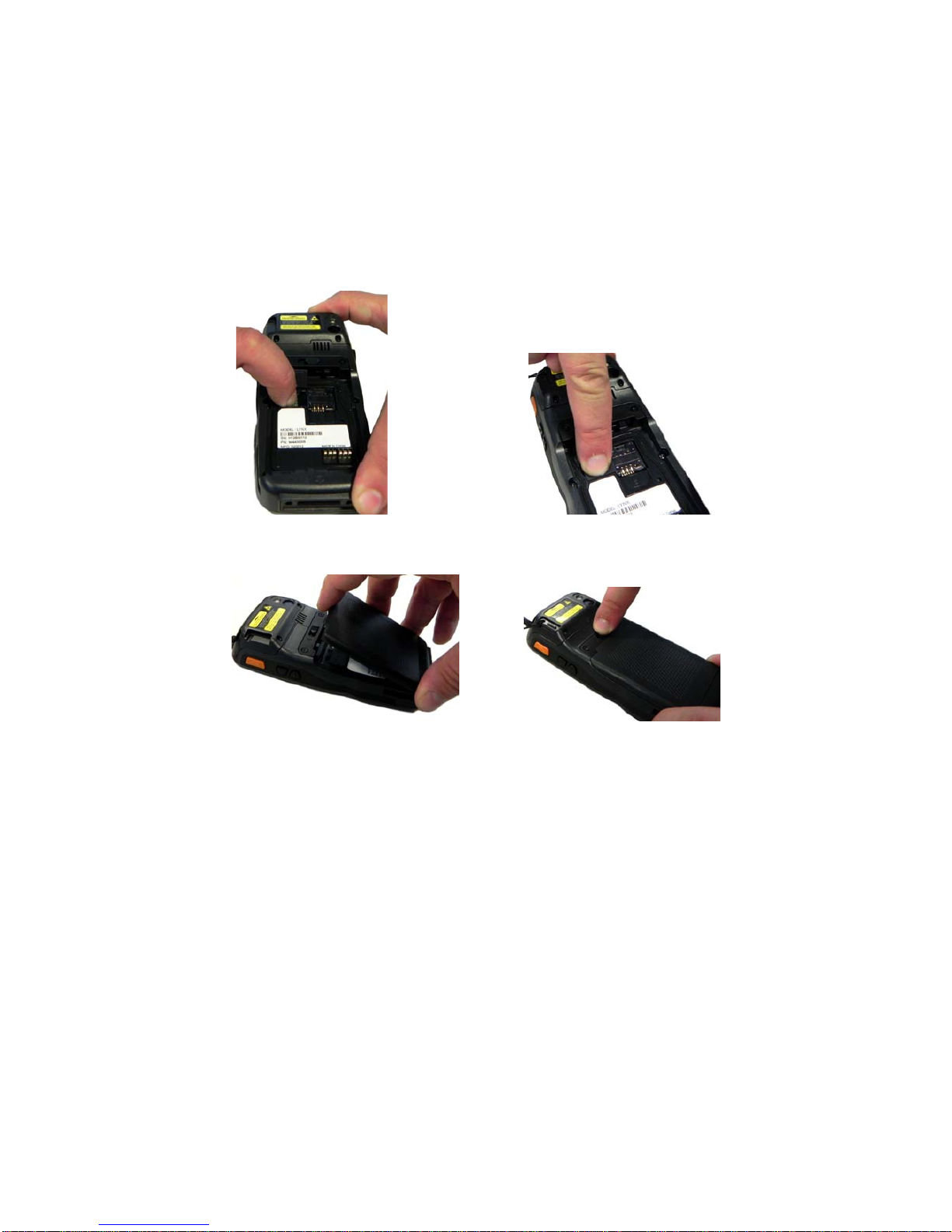
4. Shift the card to the right to lock it into the cardholder; close the card slot:
5. First insert the bottom (contacts) and then the upper side of the battery pack into
the slot. Press until the battery latch clicks..
Page 8

1.4.1 Removing the MicroSD Card
To remove the microSD card, follow the steps above to access the microSD card
cage under the battery, and remove it from microSD slot.
Follow proper ESD precautions to avoid damaging the
microprocessors in the Lynx or the microSD card itself.
Proper ESD precautions include, but are not limited to, working on
an ESD mat and ensuring that the operator is properly grounded.
Do not force the card. If you feel resistance, remove the card, check
the orientation, and reinsert it.
Do not use the microSD card slot for any other accessories.
It is highly recommended that users latch the card cage's bale even
when the card is not present.
CAUTION
Page 9

1.5 INSTALLING THE SIM CARD
To correctly insert the SIM Card, proceed as follows:
1. Turn off the Lynx.
2. Shift the battery latch to the left and remove the battery pack:
3. Insert the SIM card with the contacts downwards:
4. First insert the bottom (contacts) and then the upper side of the battery pack into
the slot. Press until the battery latch clicks.
Page 10

Follow proper ESD precautions to avoid damaging the SIM card.
Proper ESD precautions include, but are not limited to, working on
an ESD mat and ensuring that the operator is properly grounded.
Do not force the card. If you feel resistance, remove the card, check
the orientation, and reinsert it.
Do not use the SIM card slot for any other accessories.
CAUTION
1.5.1 Removing the SIM Card
To remove the SIM card, follow the steps above to access the SIM area, and remove
it from its slot.
All the basic functionalities normally associated to the SIM card are
managed by the terminal (GPRS connectivity, phone calls, SMS
handling).
All core functionalities (GPRS connectivity, phone calls, and SMS
handling) is managed by the terminal. Advanced functionality may
require additional software from the SIM card vendor.
It is possible that not all the services connected to the SIM card can
be used or can be managed by the terminal.
NOTE
Page 11

1.6 ACCESSORIES
Cradles
94A150036 Dock, Single Slot, Lynx
94A150037 Charger, 4 Slot Dock, Lynx
94A150038 Dock, Ethernet 4 Slot, Lynx
94A150039 Charger, 4 Slot Battery, Lynx
Batteries
94ACC0064 Battery, Standard Capacity, Lynx
94ACC0065 Battery, High Capacity, Lynx
Power Supply
94A051975 Power Adapter, 12 to 24v Pwr Plug 2.1mm
94A051976 Adapter, Pwr Jack 2.1mm To Handylink
94ACC1380 Power Supply, Micro USB
94ACC1381 Power Supply, Dock, PWR Plug 2.1mm
Cables
94A051020 Cable for dock-PC (RS232) communication
94A051968 Cable, Micro USB, Client
94A051969 Cable, Micro USB, Host
94A051970 Cable, USB Handylink, Client
94A051971 Cable, USB Handylink, Host
94A051972 Cable, RS232 Handylink, Client
94A051973 Cable, RS232 Handylink, Host
94A051974 Cable, Dex Handylink
Various
95ACC1033 Screen Protector Kit, 5 Pack
94ACC1230 Swivel for Functional Case (10pcs)
94ACC1345 Stylus Pen (10 pcs.)
94ACC1371 Module, Ethernet, Single Slot Dock
94ACC1372 Module, Modem, Single Slot Dock
94ACC1382 Stylus, Guitar Pick W/ Cord (5pcs)
Page 12

Use only a Datalogic ADC-approved power supply and cables. Us e
of an alternative power supply will invalidate any approva l given to
this device and may be dangerous.
NOTE
Page 13

2. BATTERIES AND MAINTENANCE
Rechargeable backup batteries and battery packs are not initially
charged. Therefore the initial operation to perform is to charge them.
See below.
NOTE
By default, the battery pack is disconnected at the factory to avoid
damage due to excessive draining.
Annual replacement of rechargeable battery pack avoids possible
risks or abnormalities and ensures maximum performance.
CAUTION
1.1 CHARGING THE BATTERY PACK
The battery pack autonomy varies according to many factors, such
as the frequency of barcode scanning, RF usage, battery life,
storage, environmental conditions, etc.
NOTE
The battery icon on the Taskbar indicates when the battery pack is low.
It is possible to recharge the battery pack by connecting the power supply directly to
the Lynx.
Alternatively, it is also possible to recharge the battery pack by using the single slot
dock, the powered mobile dock, the Ethernet four slot dock or the four slot battery
charger.
Moreover recharging is possible by USB Direct connection with the host computer,
but with longer charging times and only if the PDA is off.
During the charging process the LED positioned at the left side of the display is red
constant. Once the charging process has been completed this LED is green constant
(see par. 오류! 참조 원본을 찾을 수 없습니다.).
If the battery pack is removed from the PDA, it can be recharged by inserting it into
the rear slot of the single slot dock, the powered mobile dock, the Ethernet four slot
dock or the four slot battery charger.
Page 14
It’s recommended to charge batteries before first use.
NOTE
Risk of explosion if battery is replaced by an incorrective type.
Dispose of used batteries according to the instructions.
CAUTION
Il y a risque d’explosion si la batterie est remplacée par une batterie
de type incorrect.
Mettre au rebut les batteris usagées conformément aux instructions.
CAUTION
Avoid storing batteries for long periods in a state of full charge or very
low charge.
We recommend charging the battery pack every two to three months
to keep its charge at a moderate level to maximize battery life.
CAUTION
Even if the storage temperature range is wider, In order to achieve
the longest battery life, store the terminal and the spare batteries
between 20 to 30 ºC (68 to 86 ºF).
Extended batteries must be charged at a temperature ranging from
0° to +45°C (+32° to +113°F).
Standard batteries must be charged at a temperature ranging from 0°
to +45°C (+32° to +113°F).
NOTE
The battery level may display incorrectly for several minutes after the
Lynx is disconnected from its charger if the charging cycle is not
completed.
NOTE
Page 15

The Lynx could get warm during charging, this is normal and does
not mean a malfunction.
NOTE
Use only a USB-IF compliant USB port as a charging source.
NOTE
Page 16

1.2 REPLACING THE BATTERY PACK
To correctly replace the battery pack, proceed as follows.
1. Turn off the Lynx.
2. Shift the battery latch to the left and remove the battery pack:
3. Install the new battery pack, first insert the bottom (contacts) and then the upper
side of the battery pack into the slot. Press
until the battery latch clicks.
Page 17

WARNING
Installing, charging and/or any other action should be done by
authorized personnel and following this manual.
The battery pack may get hot, explode, ignite, and/or cause serious
injury if exposed to abusive conditions.
If the battery pack is replaced with an improper type, there is risk of
explosion.
Do not place the battery pack in or near a fire or heat; do not place
the battery pack in direct sunlight, or use or store the battery pack
inside unventilated areas in hot weather; do not place the battery
pack in microwave ovens, dryer, high pressure containers, on
induction cookware or similar device. Doing so may cause the
battery pack to generate heat, explode or ignite. Using the battery
pack in this manner may also result in a loss of performance and a
shortened life expectancy.
Use only a Datalogic ADC approved power supply. The use of an
alternative power supply will void the product warranty, may cause
product damage and may cause heat, explode or ignite.
The area in which the units are charged should be clear of debris
and combustible materials or chemicals.
Do not use the battery pack of this terminal for power devices
different from this PDA.
Immediately discontinue use of the battery pack if, while using,
charging or storing the battery pack, the battery pack emits an
unusual smell, feels hot, changes colour or shape, or appears
abnormal in any other way.
Do not short-circuit the battery pack contacts connecting the positive
terminal and negative terminal. This might happen, for example,
when you carry a spare battery pack in your pocket or purse;
accidental short–circuiting can occur when a metallic object such as
a coin, clip, or pen causes direct connection of the contacts of the
battery pack (these look like metal strips on the battery pack). Short–
circuiting the terminals may damage the battery pack or the
connecting object.
Do not apply voltages to the battery pack contacts.
Do not pierce the battery pack with nails, strike it with a hammer,
step on it or otherwise subject it to strong impacts or shocks.
Page 18

WARNING
Do not disassemble or modify (i.e. bend, crush or deform) the battery
pack. The battery pack contains safety and protection devices,
which, if damaged, may cause the battery pack to generate heat,
explode or ignite.
In case of leakage of liquid from the battery, avoid contact with liquid
the skin or eyes. If the contact occurs, immediately wash the affected
area with water and consult a doctor.
Do not solder directly onto the battery pack.
Do not expose the battery pack to liquids.
Avoid any knocks or excessive vibrations. If the device or the battery
is dropped, especially on a hard surface, you should take it to the
nearest Authorised Repair Centre for inspection before continuing to
use it.
Do not replace the battery pack when the device is turned on.
Do not remove or damage the battery pack’s label.
Do not use the battery pack if it is damaged in any part.
Battery pack usage by children should be supervised.
Collect and recycle waste batteries separately from the device in
comply with European Directive 2006/66/EC, 2002/95/EC,
2002/96/EC and subsequent modifications, US and China regulatory
and others laws and regulations about environment.
In order to guarantee an adequate operating autonomy, when
replacing the battery pack the PDA checks the battery energy level.
If the battery is not sufficiently charged, Lynx does not turn on (when
pressing the ON/OFF key).
In this case, either substitute the battery pack with a charged one
(sufficiently charged) or insert Lynx into a powered cradle or plug it
into the direct power supply.
NOTE
To maximize battery life, turn off radios when they are not needed.
NOTE
Page 19

1.3 CLEANING THE PDA
Periodically clean the Lynx with a slightly dampened cloth.
Do not use alcohol, corrosive products or solvents.
Page 20

3. CONNECTIONS
1.1 USB CONNECTION
You can use the standard micro USB cable 94A051968 or the Datalogic Handylink
cable 94A051970 to directly connect the Lynx to a host computer to transfer data
through the USB interface.
Key:
A Host computer C Lynx
B Standard Micro USB cable
94A051968/ 94A051970 Handylink
USB Client Cable
Connection through the cable complies to the 1.1 USB standard.
NOTE
A
B
C
Page 21

The Single Dock can be connected to the Host by means of the Micro-B USB cord
94A051968.
Once the host has been turned on, insert the Lynx PDA into the cradle.
Key:
A Host computer C 94A150036 Lynx Single Slot Dock
B 94A051968 Micro USB Client
Cable
D 94ACC1381 Power Adapter
Connection through the cradle complies to 1.1 USB standard.
NOTE
The actual data transfer speed can be appreciably lower than the
maximum theoretical speed.
NOTE
B
D
C
A
Page 22
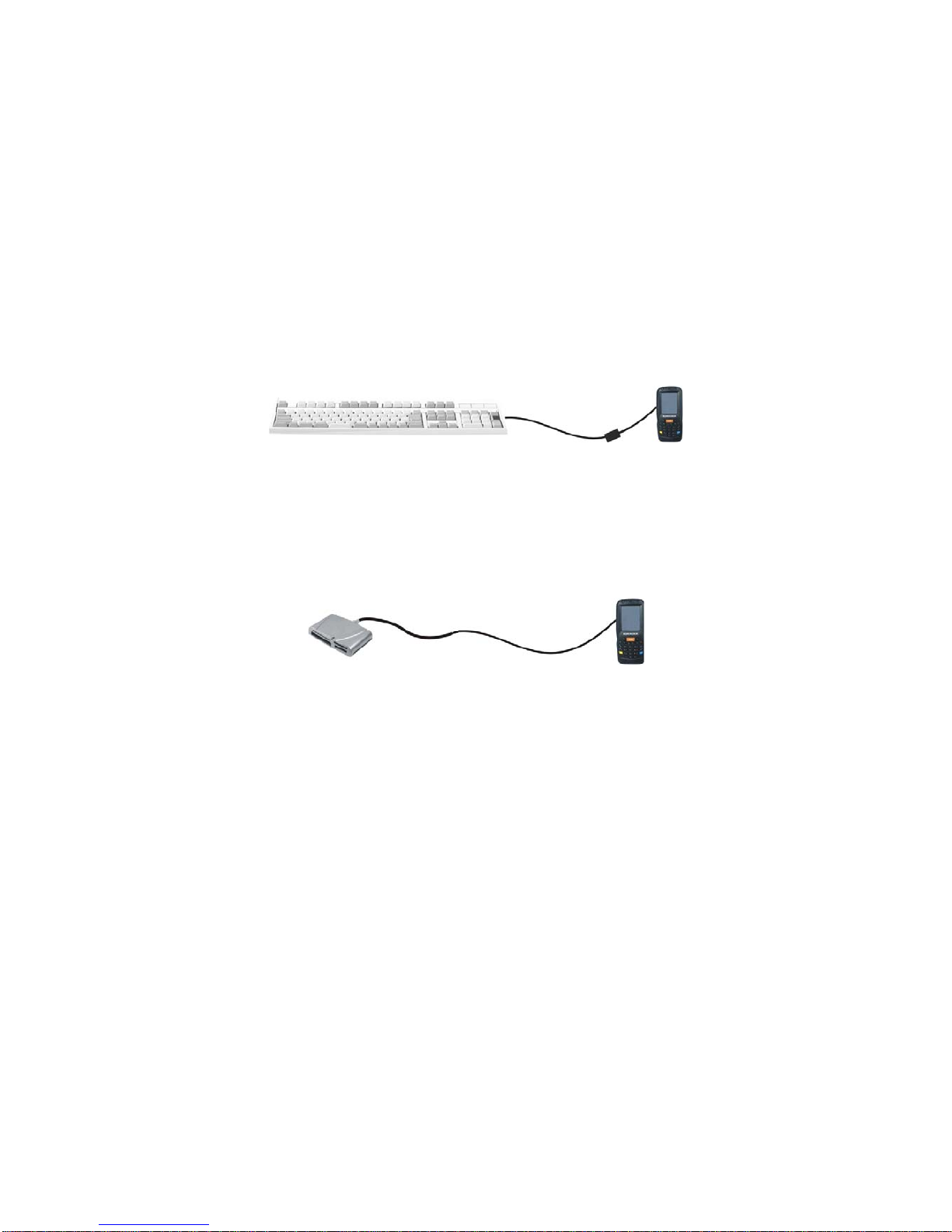
1.2 CONNECTION TO USB PERIPHERALS
To connect the Lynx to a keyboard or a memory, connect the terminal to the
Datalogic 94A051969 cable or to the Datalogic 94A051971 cable (together with a
standard A to micro A USB cable).
For all these devices maximum current withdrawal must be below 100mA.
Key:
A Keyboard with USB interface C 94A051969 Micro USB Host Cable/
94A051971 Handylink Micro USB Host
Cable
B Lynx D Standard A to Micro A USB Cable
Key:
A USB hard drive/ external
memory source
C 94A051969 Micro USB Host Cable/
94A051971 Handylink Micro USB Host
Cable
B Lynx D Standard A to Micro A USB Cable
A
B
C
D
A
B
C
D
Page 23

Connect the Single Slot Dock to the peripheral by means of a Micro-A USB cord, or
use a Micro-A to Std-A receptacle USB adapter such as Datalogic 94A051969
(together with a standard USB cable if needed).
A USB Peripheral (memory) D Standard A to Micro A USB Cable
B Lynx Single Slot Dock E 94ACC1381 Power Adapter
C 94A051969 Micro USB Host
Cable
Lynx works with most of mentioned USB peripherals. Datalogic can
not guarantee the operations of Lynx with all devices on the market.
NOTE
Connection is compliant to 1.1 USB standard.
NOTE
The actual data transfer speed can be appreciably lower than the
maximum theoretical speed.
NOTE
B
D
C
A
E
Page 24

1.3 RS232 CONNECTION
You can use the Datalogic 94A051972 cable to directly connect the Lynx to a host
computer to transfer data through the RS232 interface
Key:
A Host computer C Lynx
B 94A051972 Handylink
Micro RS232 Client Cable
The Single Slot Dock can be connected to the Host by means of a standard null
modem cable such as Datalogic 94A051020 CAB-427 for 9-pin connections.
Once the Host has been turned on, insert the Lynx PDA into the cradle.
Key:
A Host Computer C Lynx Single Slot Dock
B 94A051020 CAB-427
RS232 Null Modem Cable
D 94ACC1381 Power Adapter
A
B
C
A
B
C
D
Page 25

1.4 WLAN CONNECTION
Lynx 802.11 b/g/n radio models can communicate with the host using the on-boar d
radio frequency component and an Access Point connected to the host computer.
For models using the 802.11 b/g/n radio, you can find information about the applet for
radio configuration: http://www.summitdata.com/SCU.htm
.
To launch this utility you can tap the specific icon if it's visible on the taskbar or you
can select the menu item: Start->Programs->Summit and tap the ‘SCU’ icon.
Key:
A) Lynx
B) Access point
C) Host – Application Server
A
B
C
A
Page 26

802.11 b/g/n radio module is on by default, in order to avoid wasting
energy, you can switch it off using the SCU.
NOTE
Suspending the terminal powers off the 802.11 b/g/n radio and drops
the radio connection. When the terminal resumes, depending on the
radio power mode and security protocol selected, it may take up to
30 seconds for the 802.11 b/g/n radio driver to re-associate the radio
to the network.
NOTE
Area coverage and radio performance may vary, due to
environmental conditions, access points types or interference caused
by other devices (microwave ovens, radio transmitters, etc.).
NOTE
In case of heavy usage the Lynx could get warm, this is normal and
does not mean a malfunction.
NOTE
Page 27
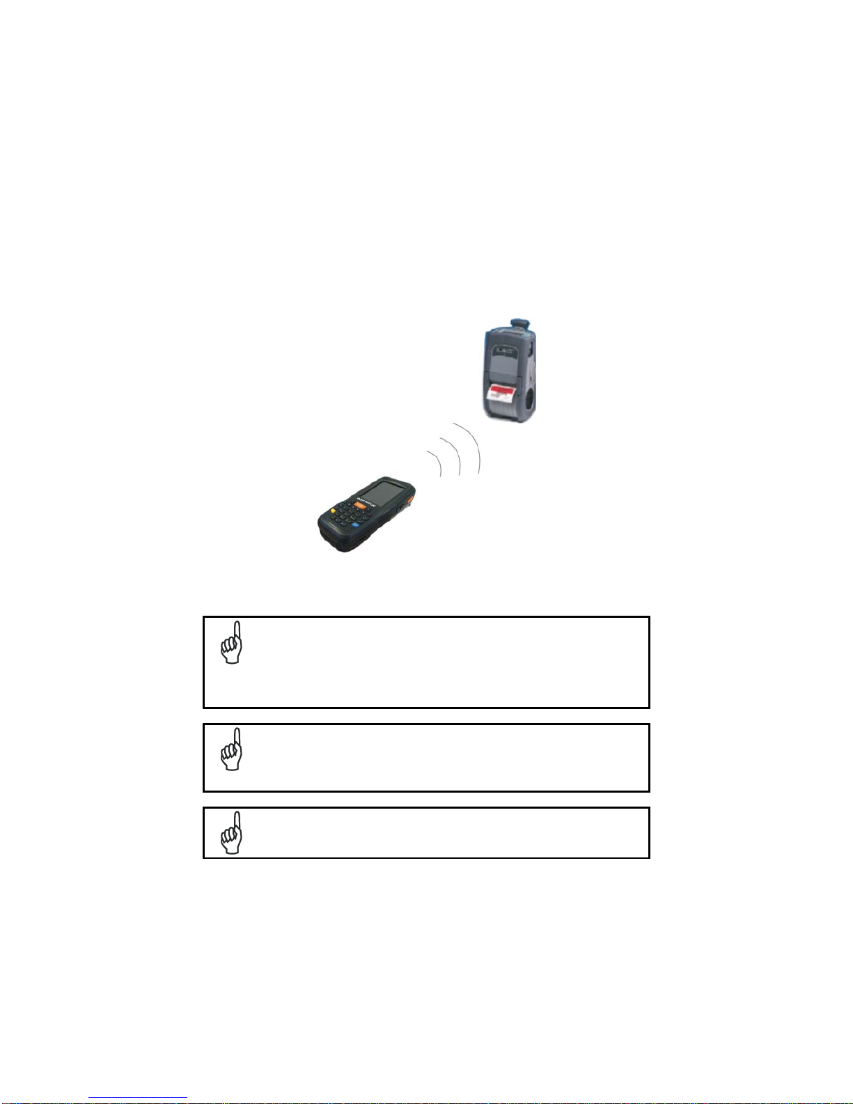
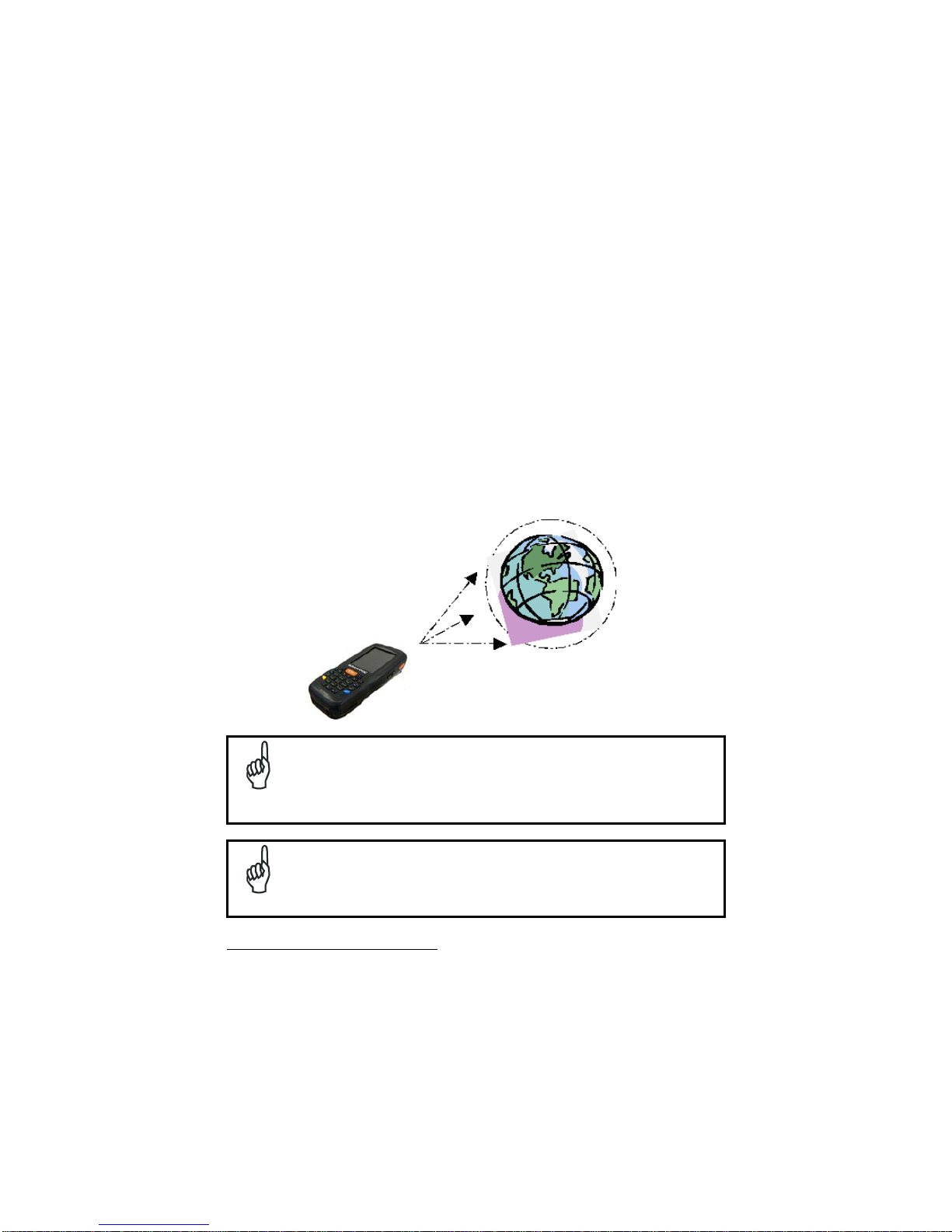
1.5 WPAN CONNECTIONS
Lynx Bluetooth®, models can communicate with a Bluetooth®, device, such as a
printer, within a range of 10 m, using the on-board Bluetooth®, module.
Key:
A) Lynx
B) Bluetooth®, printer
In order to extend battery life, the Bluetooth®, module is off by
default. If you need to have Bluetooth® working, the module must be
powered on using the Wireless Communications applet (see par.
오류! 참조 원본을 찾을 수 없습니다
.), and perform the Discovery
procedure (see par.
오류! 참조 원본을 찾을 수 없습니다
.).
NOTE
Suspending the terminal powers off the Bluetooth® radio and drops
the piconet (Bluetooth® connection). When the terminal resumes, it
takes approximately 10 seconds for the Bluetooth® radio driver to reinitialize the radio.
NOTE
Area coverage and Bluetooth® radio performance may vary, due to
environmental conditions or interference caused by other devices
(microwave ovens, radio transmitters, etc.).
A
B
Page 28

NOTE
Page 29
1.6 WWAN CONNECTION
Lynx GSM models enhance your connectivity solutions giving you an ope ning to an
international wireless infrastructure that is the global standard.
GSM (Global System for Mobile communications) is a digital mobile phone system
based on TDMA; it utilizes the 850, 900, 1800 and 1900 MHz bands.
Micro‐PDA,comeElf,èancheUMTS/HSDPA.
Bande:UMTS/HSPA+:800/850/900/1900/2100MHz‐
GSM/GPRS/EDGE85090018001900MHzforvoiceanddata
communication.
In order to use a WWAN Connection you have to install a SIM Card
(see instructions
on par. 1.5).
In order to avoid wasting energy, the GSM module is off by default. If
you need to have GSM working, the module must be powered on
using the Wireless Communications applet (see par.
오류! 참조
원본을 찾을 수 없습니다
.).
NOTE
Suspending the terminal powers off the GSM radio and drops the
connection. When the terminal resumes, if the connection was
managed by Microsoft Internet Explorer, it is automatically restored,
otherwise, the radio connection must be manually re-initialized.
NOTE
the SIM Card option is not available in 802.11 a/b/g radio and batch models
Page 30

The GSM voice capability of this PDA has to be addressed to
occasional use, in well covered areas.
If the coverage is poor, the voice quality can be highly affected.
NOTE
Page 31

Calls can be made or received using the Ly nx as a phone handset,
by the Lynx headset or by a Bluetooth® headset.
NOTE
During a call, you can set the speaker volume by pressing the arrow
navigation keys.
NOTE
In case of heavy usage the Lynx could get warm, this is normal a nd
does not mean a malfunction.
NOTE
Page 32

1.7 WIRELESS AND RADIO FREQUENCIES WARNINGS
Use only the supplied or an approved replacement antenna.
Unauthorized antennas, modifications or attachments could
damage the product and may violate laws and regulations.
WARNING
Most modern electronic equipment is shielded from RF signals.
However, certain electronic equipment may not be shielded against
the RF signals generated by Lynx.
WARNING
Datalogic recommends persons with pacemakers or other medical
devices to follow the same recommendations provided by Health
Industry Manufacturers Associations for mobile phones.
Persons with pacemakers:
Should ALWAYS keep this device more than twenty five (25) cm
from their pacemaker and/or any other medical device;
Should not carry this device in a breast pocket;
Should keep the device at the opposite side of the pacemaker
and/or any other medical device;
Should turn this device OFF or move it immediately AWAY if
there is any reason to suspect that interference is taking place.
Should ALWAYS read pacemaker or any other medical device
guides or should consult the manufacturer of the medical device
to determine if it is adequately shielded from external RF energy.
In case of doubt concerning the use of wireless devices with an
implanted medical device, contact your doctor.
WARNING
Turn this device OFF in health care facilities when any regulations
posted in these areas instruct you to do so. Hospitals or health care
facilities may use equipment that could be sensitive to external RF
energy.
WARNING
Page 33

RF signals may affect improperly installed or inadequately shielded
electronic systems in motor vehicles. Check with the manufacturer
or its representative regarding your vehicle. You should also
consult the manufacturer of any equipment that has been added to
your vehicle.
WARNING
An air bag inflates with great force. DO NOT place objects,
including either installed or portable wireless equipment, in the area
over the air bag or in the air bag deployment area. If vehicle’s
wireless equipment is improperly installed and the air bag inflates,
serious injury could result.
WARNING
Turn off the device when in any area with a potentially explosive
atmosphere. Observe restrictions and follow closely any laws,
regulations, warnings and best practices on the use of radio
equipment near fuel storage areas or distribution fuel areas,
chemical plants or where some operation involves use of explos ive
materials.
Do not store or carry flammable liquids, explosive gases or
materials with the device or its parts or accessories.
Areas with a potentially explosive atmosphere are often, but not
always, clearly marked or showed.
Sparks in such areas could cause an explosion or fire, resulting in
injury or even death.
WARNING
Page 34

4. USE AND FUNCTIONING
The use of the Lynx depends on the application software loaded. However there are
several parameters that can be set and utilities that can be used to perform some
basic functions such as data capture, communications, file management, etc
1.1 STARTUP
The Lynx turns on when the battery pack or the external s upply is inserted and the
ON/OFF Power button is pressed.
After the battery pack is installed, use the [ON/OFF] key to turn the PDA on and off.
As soon as the PDA is on, the Windows Embedded Handheld 6.5 desktop
configuration will appear on the screen. Wait a few seconds before starting any
activity so that the PDA completes its startup procedure.
Today Screen Start Menu
Use the stylus (par. 1.1.1) as suggested to select icons and options.
The PDA goes into power-off (low power with display and keyboard backlight off),
when it is no longer used for more than a programmable timeout, which is defined in
the POWER applet of the Control Panel. In this mode it can be awakened (resuming
operation) by the [ON/OFF] key.
Page 35

The PDA can also be awakened or turned off by the application
program.
NOTE
1.1.1 Using the Stylus
The stylus selects items and enters information. The stylus functions like a mouse.
Tap:
Touch the screen once with the stylus to open items and select
options.
Drag:
Hold the stylus on the screen and drag across the screen to
select text and images. Drag in a list to select multiple items.
Tap-and-hold:
Tap and hold the stylus on an item to see a list of actions
available for that item. On the pop-up menu that appears, tap the
action you want to perform.
To recalibrate the touch screen use the Stylus Applet (see par. 1.6.7).
Use only original Datalogic styluses supplied with the product itself.
In harsh applications, use of screen protectors should be taken into
consideration, in order to extend the touch screen operating life.
To prevent damage to the screen, do not use sharp devices or any
device other than the Datalogic ADC -provided stylus.
Do not apply too much pressure when touching the screen.
For applications where an intensive use of the touch screen is
foreseen, please consider that touch screen components are su bject
to progressive wear.
CAUTION
Page 36

1.2 WINDOWS EMBEDDED HANDHELD WELCOME WIZARD
In Windows Embedded Handheld, at the very first Lynx startup, following a clean
boot or following a registry restore to default values, the PDA startup (see par. 1.1) is
preceded by the Welcome Wizard.
Welcome Wizard Screen
The Welcome Wizard allows the user to calibrate the touch screen (see par. 1.6.7)
and to configure an email account and a password to protect the terminal.
Touch Screen Calibration Screen
Page 37

1.3 DATA CAPTURE
To capture data first of all tap Start > Settings > System > Decoding:
To configure and enable data capture parameters refer to par. 1.6.1.
Page 38

1.3.1 Laser Data Capture
To scan barcodes, point the Lynx laser model onto the code from a distance within
the reading range while pressing the SCAN key.
The lighted band emitted by the laser must completely cross the barcode as shown in
the figure below.
If the scan has taken place correctly:
the Good Read LED gets constant Green for a configurable time;
if enabled, the GoodReadSound emits an acoustic signal;
if enabled, the GreenSpot projects a green spot onto the b ar code image.
Page 39

Remove the protective film cover over the Laser Output Window
before use.
NOTE
Page 40

1.3.2 Imager Data Capture
The Lynx Imager captures a picture of the entire bar code. The omni-directional
scanning does not require that the operator orient the bar code to align with the scan
pattern.
To read a 1D or 2D code, simply point the Lynx Imager model onto the code and
press the SCAN Key.
The Lynx Imager uses an intelligent aiming system pattern, similar to those on
cameras, indicating the field of view, which should be positioned over the code:
Aiming System
If the aiming system pattern is centered over the entire symbology as shown in the
following figure, either wait for the timeout or release the Scan key to capture the
image.
A red beam illuminates the code, which is captured and decoded. You will get a good
read.
Page 41

Linear barcode 2D Matrix symbol
Ì BX3ÉÎ
Relative Size and Location of Aiming System Pattern
The field of view changes its size as you move the reader closer or farther away from
the code. The field of view indicated by the aiming system pattern will be smaller
when the Lynx Imager is closer to the code and larger when it is farther from the
code.
Symbologies with smaller bars or elements (mil size) should be read closer to the
unit. Symbologies with larger bars or elements (mil size) should be read farther from
the unit. (See par. 오류! 참조 원본을 찾을 수 없습니다. for further details).
If the scan has taken place correctly:
the Good Read LED gets constant Green for a configurable time;
if enabled, the GoodReadSound emits an acoustic signal.
Page 42

1.4 DESCRIPTION OF THE KEYS
The Lynx comes with two different keyboards, an alphanumeric keyboard (q werty),
having 46 keys, and a numeric keyboard, having a total of 27 keys.
1.4.1 Alphanumeric Keyboard
Page 43

Numeric Keyboard
Page 44

Main Keys Function
KEY FUNCTION
It starts barcode data capture.
They let you move forwards, backwards, upwards or
downwards within text fields, scroll through a Menu list or
browse among folder files.
Yellow modifier (toggle key): when pressed before a
standard key, it enables the character or function printed
in yellow above the key.
Blue modifier (one shot key): when pressed before a
standard key, it enables the character or function printed
in blue above the key
It powers the Lynx ON or OFF. It is placed on the upper
left side of the terminal.
The hang up key normally generates the VK_TEND
virtual key code, used to hang-up phone calls.and to exit
applications.
In blue mode, the hang up key generates a
VK_ESCAPE virtual key code for applications that uses
this specific virtual key code to exit (e.g. touch screen
calibration application).
Page 45

1.4.2 Resetting the Lynx
There are several reset methods for the Lynx.
A warm boot terminates an unresponsive application an d clears the working RAM,
but preserves the file system. Registry is restored from persistent memory if available
or returned to factory default.
A cold boot forces all applications to close reinitializing completely the system. It
clears the working RAM, but the file system is preserved. Registry is restored from
persistent memory.
A clean boot restores the Lynx to a clean configuration: both the registry and the file
system returns to a clean status that conforms to factory default.
Warm Boot
To perform a warm boot, press and hold the following keys simultaneously:
Cold Boot
To perform a cold boot, do the following steps:
1. Turn off the Lynx by pressing the on-off key.
2. Pull the battery latch down and remove the battery pack.
3. Press the reset button.
4. Insert the battery pack.
5. Turn on the Lynx by pressing the on-off key.
Page 46

Clean Boot
To perform a clean boot, do the following steps:
1. Perform a Cold Boot (see Cold Boot)
2. Press and hold down the 0 and hang up keys simultaneous ly and then pre ss the
on-off key:
+
A dialog box will appear asking for confirmation. Press the Enter Key.
Warm Boot Cold Boot Clean Boot
Registry
Restored from
flash
Restored from
flash
Clean configuration (no user
config)
File
System
Preserved Preserved Clean Installation (no user files)
Page 47

1.5 STATUS INDICATORS
1.5.1 LED Status
The Lynx provides three different LEDs signaling the PDA status.
LED STATUS
Good Read
(right side)
Red
Scanning LED is ON from the time the
user hits the scan button (Trigger) until
the bar code is decoded (laser models)
Time-out (imager models).
Green
Scanning LED is ON, showing a good
decode.
Charging Status
(left side)
Green
It is constant once the charging process
has been completed (full charge).
Red It is constant while charging.
Red blinking
In case of charge fault it is constant for
two hours, then it starts blinking.
Keyboard Status
(center)
Off Keyboard in primary.
Yellow solid Yellow alternate key mode.
Blue solid Blue alternate key mode
Pink CapsLock enabled.
Page 48

1.5.2 Taskbar
The Taskbar provides information about the time, the battery level, the keyboard
function, and the decoding status.
Windows Embedded Handheld Taskbar
ICONS DESCRIPTION
Zooms the screen.
Opens the Wireless Manager (see par. 1.6.6).
Displays the system battery status.
Allows to set the volume of screen taps.
Opens Clock & Alarms application. It allows to set date, time
and alarms.
Page 49

1.6 CONTROL PANEL
From the Start menu, tap Settings. The Control Panel is split into three sections:
Personal, System, Connections.
Control panel applets are displayed as icons; each icon corresponds to on e applet:
Windows Embedded Handheld Control Panel
Page 50

1.6.1 Data Capture Configuration
You can configure the Lynx’s decoding options by tapping Start -> Settings ->
System -> Decoding:
There are two sections in the Decoding control panel, each containing additional
pages. There are seven General Configuration pages and multiple Barcode
symbology pages.
DECODING CONFIGURATION PAGES
Select the desired configuration from the options shown in the figure bel ow, and the
other Decoding Properties figures on the following pages.
Select General or 1D Bar Code, then use the menu or tap the left and right arrow
keys to navigate the different pages of the Decoding utility. The menu options will
change to reflect the items most recently selected.
Page 51

Audio
From the Decoding menu, tap Configure > General > Audio. Use it to set volume,
tone, duration, and number of various types of beeps.
Good Read
From the Decoding Properties page, tap Configure > Gener al > Good Rea d. Use it to
enable Good Read indications, the use of Green Spot and a to set the decoding
timeout for decoding labels.
Page 52

Formatting
From the Decoding Properties page, tap Configure > Gener al > Formatting. Use it to
configure prefix, suffix and data separator character strings.
General Options
From the Decoding menu, tap Configure > General > General Options. Select from
Label Programming Enable, Symbology IDs and Group Separator Replacement.
Page 53

Decoding Options
From the Decoding Properties page, tap Configure > General > Decoding Options.
Use it to configure the User ID for symbologies, Redundancy and Aggressive
Decoding (if supported by the decoding module). Select a symbology to view or
change the available properties settings.
Page 54

Spot Beam
From the Decoding Properties page, tap Configure > General > Spot Beam. It allows
enabling and configuration of Spot Beam and triggering modes.
It is only available on devices equipped with las er and advanced long range laser
decoding modules that support the Spot Beam Feature.
Page 55

Imager Options
From the Decoding Properties page, tap Configure > General > Imager Options. It
configures illumination, target beam and Pick List mode, and triggering modes.
It is only available on devices equipped with 2D decoding engines.
Page 56

Devices
From the Decoding Properties page, tap Configure > General > Dev ices. Use it to
enable or disable the keyboard wedge for Barcode scanner.
Page 57

1D Barcode Symbology Pages
Use the drop-down menus from Configure > 1D Barcode, or tap th e left and right
arrow keys to navigate the different pages of the barcode symbology pages.
Each barcode symbology opens to its own page, as shown in the figure below. Refer
to the sample symbology control panels for examples of the types of fields and
options you can modify.
Codabar: Select Enable, Min/Max Lengths, Enable Checksum, Send Checksum,
Send Start/Stop, Convert to CLSI and Wide Gaps.
Page 58

Decoding Settings
Select from the Decoding Properties Settings menu to restore previous
configurations and/or other available default settings. Choose from:
Factory Defaults
Minimum Settings
Maximum Settings
Save (New Settings)
Revert to Saved Settings
The settings are saved when you tap OK.
The settings are saved when you tap ‘Yes’.
When open, Decoding Properties acts as a simple barcode test tool that provides th e
Data decoded and the Data Type of the barcode scanned.
Page 59

1.6.2 Buttons
From the Start menu, tap Settings > Personal > Buttons.
On the Program Buttons tab, customize the program hardware buttons to launch your
most used applications. Under ‘Select a button’, tap the button you want to assign a
program to, and then select a program from ‘Assign a program’.
To configure the way the up/down control repeats, use the Up/Down Control applet
(Start > Settings > Personal > Buttons > Up/Down Control).
Page 60

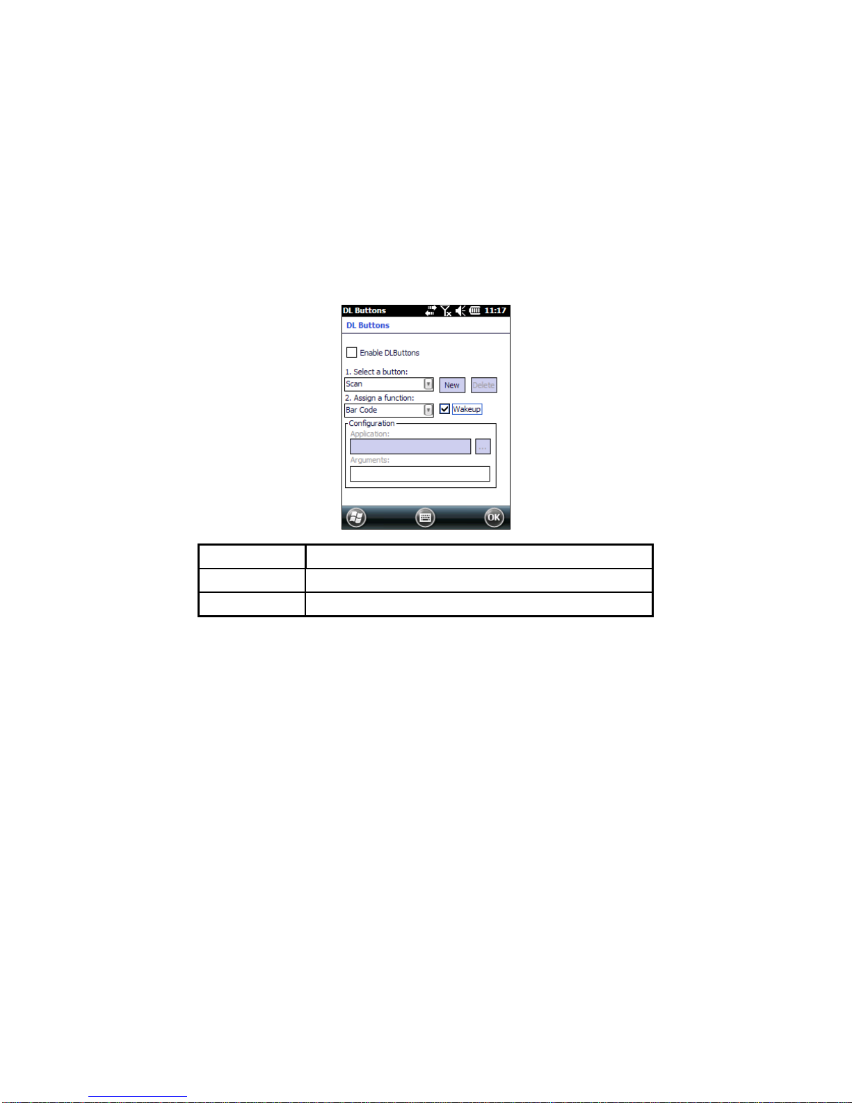
1.6.3 DL Buttons
In Windows Embedded Handheld devices, <F1>-<F10> buttons (excluding F5) are
assigned by Windows to default applications.
To customize one of these buttons and assign it to a different application, you first
need to disable it. Tap Start > Settings > System > DL Buttons to display the DL
Buttons window:
Select the button you want to disable. Select the function ‘None’ and the click OK.
To remove the disabled button, select it and click ‘Delete’.
Page 61

A dialogue box appears, asking for confirmation. Click ‘Yes’:
To add the button back, click ‘New’ and write the name of the button on t he box that
appears:
Page 62

To assign a new application to the button, select the function and then click ‘OK’:
To restore the old settings , do a clean boot.
Page 63
1.6.4 Triggers
Triggers are special customizable buttons that are mapped by default by DL Mobile.
Also, they can be set as wakeup buttons:
TRIGGER APPLICATION
Scan Bar Code
Pistol Trigger
Bar Code
Page 64

1.6.5 Application Switcher
The application switcher provides the same functionality as the standar d Windows®
Alt+Tab function. This allows the user to switch between the various open
applications.
The application switcher is activated via an assigned shortcut key specified in the “DL
Buttons” tab (refer to par. 1.6.3). When the assigned button is pressed, the dialog
shown below will be displayed:
The <Esc> key can be used to close the Application Switcher.
NOTE
Press the assigned button to open the application switcher. Press the assigned
button to cycle through the running applications when the dialog is open. Press
<Enter> to switch to the selected application or <Esc> to close the application
switcher.
Page 65

1.6.6 Wireless Communications
The Wireless Manager application is a sort of 'Control Panel' for wireless connections.
From here it's possible to turn on or off bluetooth® and radio modules.
Open the Wireless Manager by tapping Start > Settings > Connections > Wireless
Manager, or by tapping the connectivity icon on the taskbar (see par. 오류! 참조
원본을 찾을 수 없습니다.). The following window will appear:
Page 66

Summit Client Utility (SCU)
Wireless networking has a customized control, Summit Client Utility (SCU), specific
to the radio. From the Start menu, tap: Summit > SCU:
The SCU will open to the “Main” tab:
Summit Client Utility
Page 67

1. To create a new profile, tap the "Profile" tab:
Information about the wireless network can be entered directly in the profile tab or by
pressing “Scan” when the desired network ESSID is in range.
2. At the "Scan" screen, select the desired SSID:
Page 68

3. Click the "Configure" button
4. Follow the on-screen instructions to setup security parameters for your network.
For more detailed settings specific to your installation please contact your
wireless network administrator.
5. When finished, click “Commit” to save your settings.
Return to the “Main” tab, if you have not previously selected “Commit” you will be
prompted to save your changes.
Page 69

At the “Main” tab select the profile you just created. If you used the “scan” button the
desired profile will have the same name as the ESSID.
Use the “Status” tab to check connectivity to the network.
More detailed information about the applet for radio configuration can be found at
http://www.summitdata.com/SCU.htm.
Page 70

1.6.7 Stylus Calibration
You might need to recalibrate the touch screen (i.e. when you attempt to select one
item with the stylus, another item is erroneously selected).
To recalibrate the touch screen, complete the following steps:
1. Select Start > Settings > System > Screen to open the Screen
Settings dialog as shown in the figure below:
2. Tap Align Screen to open the Calibration screen shown in the figure below.
3. Carefully press and briefly hold stylus on the center of the target. Repeat as the
target moves around the screen.
4. By completing the calibration procedure you implicitly accept the new calibration
settings.
5. New calibration settings are persistently saved in registry.
Page 71

Startup Stylus Calibration
When starting the terminal, a Welcome Wizard (with Stylus Calibration) comes up if
valid calibration settings are not available. This happens in the following
circumstances:
1. At the first startup of the terminal.
2. After any cold boot if the user skipped stylus calibration earlier.
3. After a Clean Boot.
Page 72
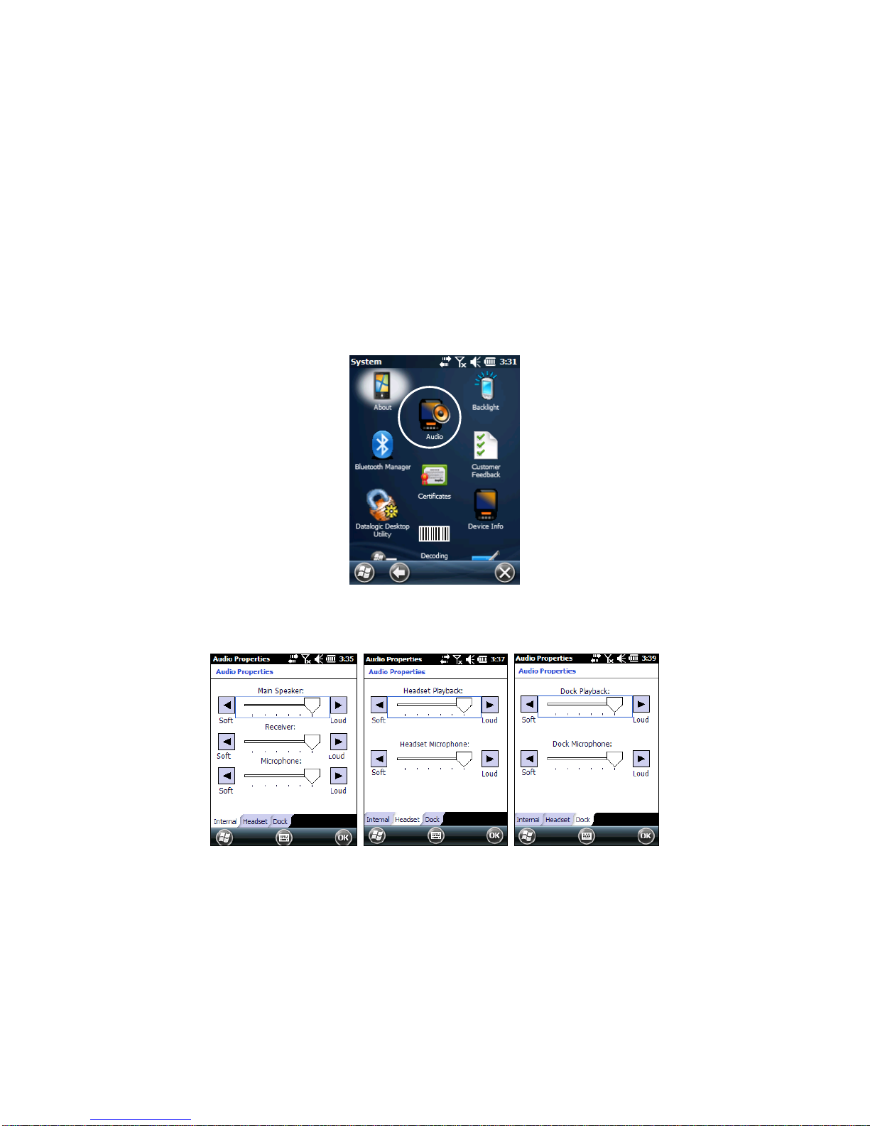
1.6.8 Audio Settings
There are two applets that control volume: Audio and Volume & Sounds.
Audio
From the Start Menu, tap Settings > System > Audio:
The audio control panel can be used to independently s et the playback or recording
volume for different types of audio inputs and outputs, such as a headset, powered
mobile dock, or the internal speakers and microphone.
Audio Windows
Page 73

Sounds & Notifications
From the Start Menu, tap Settings > Sounds and Notifications:
The Volume & Sounds applet configures audio features of all speakers and
headphones:
Sounds Tab Notifications Tab
Page 74

To set the Bluetooth® headset volume, you can also tap:
Start > Settings > System > Bluetooth Manager > Connections and select the
headset. The following window will appear:
Page 75

1.7 WINDOWS CONNECTIONS
To connect the Lynx to another device (i.e. Host PC) from Windows, several
programs are available. These programs require specific electrical connections in
order to function properly.
1.7.1 Windows Mobile® Device Center
The desktop application Windows Mobile® Device Center gives you the ability to
synchronize information between a desktop computer and your Lynx.
Synchronization compares the data on the Lynx with that on the desktop
computer and updates both with the most recent information.
Windows Mobile® Device Center is only compatible with Windows Vista and
Windows
7; if you run Windows XP or earlier, you have to download Microsoft ActiveSync.
You can establish a connection to your Lynx through the following interfaces:
USB either directly or through the Single Dock
RS232 either directly or through the Single Dock
Bluetooth® (see par. 1.7.2)
To establish a partnership between the Lynx and a host PC, start Windows Mobile®
Device Center and follow the steps below:
1. Connect the Lynx to the host PC. Windows Mobile® Device Center configures
itself and then opens.
2. On the license agreement screen, click Accept.
3. On the Windows Mobile® Device Center’s Home screen, click Set up your
device.
4. Select the information types that you want to synchronize, then click Next.
5. Enter a device name and click Set Up.
When you finish the setup wizard, Windows Mobile® Device Center synch ronizes the
mobile computer automatically. Microsoft® Office Outlook® emails and other
information will appear on your device after synchronization.
Page 76

Visit the following Microsoft Web site for the latest in updates and
technical information:
http://www.microsoft.com/windowsphone/enus/howto/wp6/sync/prepare-to-sync-windows-phone-6-5-with-mycomputer.aspx
NOTE
When a microSD card is inserted, Lynx allows a mass storage dat a
connection to a host PC. This functionality can be enabled through
the Control Panel. When doing so, the microSD card is not available
to the Lynx. An ActiveSync connection is not possible when this
feature is enabled.
NOTE
Page 77

1.7.2 Bluetooth®, Manager Device Setup
The Bluetooth® Manager icon will only be visible if Bluetooth®
hardware has been installed on the unit.
NOTE
Using the Lynx to connect to another device
To create a Bluetooth® pairing between your device and another device that has
Bluetooth® capabilities, ensure that the two devices are tur ned on, discov erable, and
within close range.
1. Open the Bluetooth® control panel by tapping Start > Settings > System >
Bluetooth Manager:
2. Search for available Bluetooth® devices by tapping the button for the type of
device you want (Printer, Serial or All) or tap Discovery > Discover to skip this
step. The Lynx will search for Bluetooth® devices within range.
If you attempt to set up a connection when the Bluetooth® radio is
disabled, you will receive a message reminding you that the radio is
turned off, and asking if you want to turn it on. Tap Yes if you need to
enable the Bluetooth® radio.
NOTE
Page 78
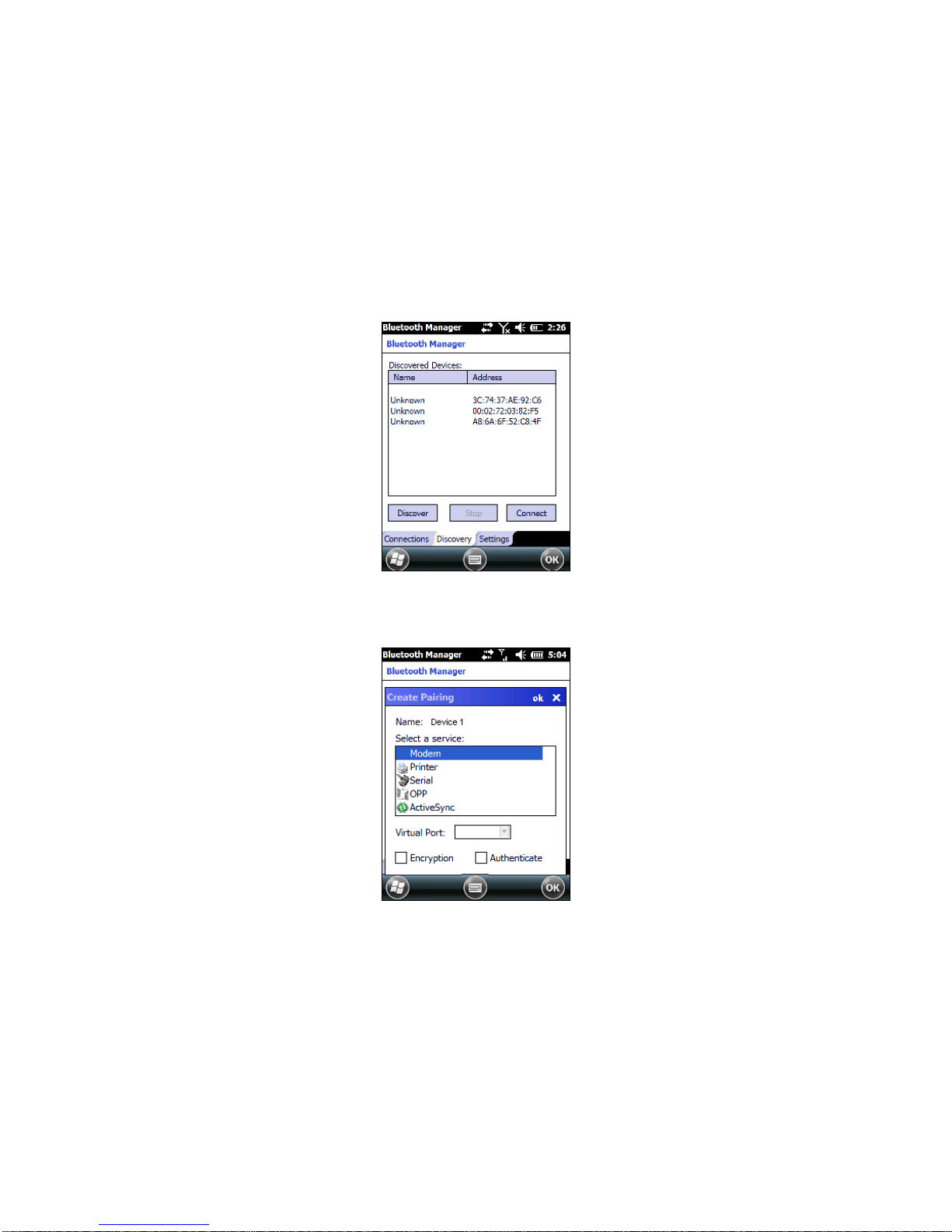
3. Once searching is complete, Bluetooth® device Profiles will be displayed in the
Discovery tab. You can set up a connection to a device in the list by selecting
the device and then tapping the 'Connect' button:
To create a pairing:
1. Select a service:
2. Configure any encryption, authentication, or virtual port options required by the
service selected.
Page 79

Icon Service
Dialup Networking
Printer
Object Push (OPP) Object Exchange (OBEX)
ActiveSync
Human Interface Device (HID) - Keyboard
Serial
Personal Area Network (PAN)
Modem
Headset
Handsfree
Virtual Port allows you to specify the incoming port, which is used to communicate
serially with an incoming device just as if it were a physical COM port. This option is
available only if you have selected a Printer or Serial service.
Page 80

You can also select Encrypt or Authenticate from the Bluetooth® control panel to
apply or modify those settings.
1. To require Authentication, check the checkbox, then tap OK.
2. If required, the Authentication Request dialog will then open, requesting that you
enter a PIN. Use the Input Panel or the keyboard to type the PIN.
3. Tap OK to complete.
Page 81

The dialog will also appear when an Authentication request is receive d from another
device.
Once you have set up a Pairing, you can view the settings by double-tapping its
name from the Connections tab. Tap the arrow to change the Virtual Port, or Delete
to remove the device pairing. Tap Sync to initiate a Sync (available only if the service
is an ActiveSync connection).
Page 82

Using your device to connect to the Lynx
Before turning on Bluetooth®, ensure that the two devices are within close ran ge and
that both Bluetooth-enabled devices are discoverable.
1. Tap Start > Settings > System > Bluetooth Manager to open the Bluetooth®
control panel.
2. Tap Settings. The Settings tab allo ws you to enable or disable the Bluetooth®
radio and specify settings for Incoming Connections.
Page 83

3. Select or clear the “Enable Bluetooth Radio” check box.
If you’re going to be attaching a serial device (i.e. a scanner) to the Lynx, use
the Port control to select a virtual COM port to use for the connection.
4. Tap ‘Find Me’ if you want to make the Lynx visible to other Bluetooth® devices
for 60 seconds, allowing them to set up a connection.
Page 84

By default, Bluetooth® is turned off. If you turn it on, and then turn off
your device, Bluetooth® also turns off. When you turn on your device
again, Bluetooth® turns on automatically.
NOTE
Page 85

1.7.3 Windows Mobile Phone
For information on Windows Mobile Phone use and functioning, refer to t he Windows
Mobile web site: http://www.microsoft.com/windowsmobile
.
Page 86

1.8 SKYHOOK° XPS SETTINGS
1.8.1 XPS - Virtual GPS for Windows Mobile
Skyhook synthesizes data from Skyhook's Wi-Fi Positioning System (WPS), GPS
satellites and cell towers with advanced hybrid positi oning algorithms combining as
much as possible to build a composite position and to provide the best possible
location available in any environment.
XPS Program Icon
1.8.2 Configuring XPS
When the XPS Settings installation has completed, the settings pan el will displa y five
tabs that can be used to configure your device.
The default settings should be correct for most applications.
NOTE
You MUST click [Apply] when changing settings on each tab.
NOTE
Page 87

Storage – tab
Temporary folder:
Select the folder on your device or storage card where
the XPS application will store data files.
Temporary folder max size:
This controls the amount data storage allocated to the
XPS Settings application (default setting is 4096kb).
Port – tab
XPS Port:
Select the port that XPS will stream
location data from by default, XPS will select an unused
port.
Disabling other serial drivers:
Use this option to disable an active
device if a port for XPS is needed.
GPS - tab
COM Port:
Select the port that XPS will read the GPS data from
(default is Auto).
Baudrate:
Set the baudrate for your GPS device.
Description:
The description of the GPS as identified by Windows
Mobile.
Page 88

Service – tab
Activate / Deactivate:
Toggles the XPS service On and Off.
About – tab
About:
View the XPS version and copyright information.
1.8.3 Uninstalling XPS
To remove XPS from your Windows Mobile device:
1. Open the Settings panel
2. Open the System panel
3. Tap ‘Remove Programs’
4. Select ‘XPS Settings’ and tap remove
Page 89

1.8.4 FAQ and Troubleshooting
1. Can I install to a storage card?
Yes – however, as with most mobile apps installing to the device is
recommended.
2. What does registering XPS as my default GPS do?
Registering XPS simply sets the Windows Mobile OS to use XPS whenever
an application asks for positioning. If you choose not to set XPS as the
default, you will need to select the XPS COM port manually when configuring
an application.
3. What happens if I uninstall or deactivate XPS?
XPS will reset your system settings to what they were prior to install.
4. I’ve installed but cannot get location, what is wrong?
There are seve ral things that could cause this to happen:
Do you have an internet connection? An internet connection is required
after install for XPS to complete setup. An internet connection is also
needed if you are moving (this connection will be present if you have data
service).
Do you have wi-fi disabled? Enable wi-fi and try again.
Are you in an area with low numbers of access points? The WPS portion of
XPS requires wireless routers to be in scanning range to provide
positioning.
5. I’ve installed XPS but it will not run, what happened?
If you installed to a storage card, that card must be present in the device for
XPS to function (installing to the device is the recommended configuration).
6. My app is not providing location?
Verify that XPS is activated in the XPS Settings ‘Service’ tab and that your
app has the XPS port selecte d within your application’s settings panel.
7. My XPS settings are not being saved?
You must tap the ‘Apply’ button before exiting the tab in XPS Settings.
Page 90

1.9 DATALOGIC FIRMWARE UTILITY
The Datalogic devices are equipped with a field upgrad eable firmware mechanism.
Firmware updates are available on the Datalogic ADC website
(http://www.adc.datalogic.com/
). After you have downloaded the desired update,
there are several ways you can update the firmware on yo ur device.
Use Wavelink Avalanche™ if you have multiple Datalogic ADC devices to
update. Refer to the Product CD included with your device for more
information.
If Wavelink Avalanche™ is not available or you have only a few Datalogic ADC
devices to update, use the Datalogic Firmware Utility (DFU), described below,
to install or update the firmware using an ActiveSync connection.
The following sections provide procedures for the retrieval and installation of the
most current firmware image onto a Datalogic device.
1.9.1 Retrieving a Firmware Image Update
The following instructions use Internet Explorer to retrieve the most current firmware
image.
1. Launch Internet Explorer on your PC and navigate to the Datalogic ADC
website.
2. Navigate to the Downloads section of the website.
3. Select the file you want to download, then click Save to begin copying the files
to your local machine (or local network location).
Page 91

1.9.2 Installing DFU on the Host PC
The Datalogic Firmware Utility (DFU) provides administrators with a field upgrade
mechanism. You must have Microsoft® ActiveSync (for Windows XP devices) or
Windows Mobile® Device Center (for Windows 7 and Vista devices) already loaded
and running on the host PC to use DFU. Refer to par. 1.7.1 for more information
about Windows Mobile® Device Center.
Prior to installing, you must remove any previous versions of DFU
installed on the host PC.
NOTE
To install the Datalogic Firmware Utility, complete the following steps on the PC:
1. Insert the CD ROM shipped with your device into the PC and click on the link
to install Datalogic Firmware Utility.
OR
Go to the Datalogic ADC website and download the most current version of
the Datalogic Firmware Utility. Unzip the file, then double-click to run
DFU_Setup. exe.
Click OK to continue once you have removed previous versions of DFU.
2. The Welcome to DFU Setup Program screen opens.
Please e xit all Windows applications before running this installer.
Click Next to continue the Setup.
3. Follow the onscreen instructions to complete the installation.
Page 92

1.9.3 Updating the Firmware
After copying the firmware image to the host PC (see par. 4.10.1) and installing DFU
(see par. 1.9.2), you can upgrade the firmware on your Datalogic device.
The following steps require that you have already established an
ActiveSync or Windows Mobile® Device Center connection between
the host computer and the Datalogic device.
NOTE
1. Go to Start > Programs > DFU > Datalogic Firmware Utility.
2. Verify that ActiveSync is selected by clicking Communications > ActiveSync.
3. Click browse (...) and navigate to the locati on where you saved the firmware
file for your terminal.
4. Select the current *.out file and click Open.
5. Click Update.
6. DFU will compare the selected firmware image with the firmware already
loaded on the device; if the images are different, DFU will proceed to update
the firmware image on your device.
7. After the firmware of your device has been updated, DFU will automat ically
perform a warm reset of the device.
Page 93

1.10 DATALOGIC CONFIGURATION UTILITY
Datalogic Configuration Utility (DCU) is a Datalogic Windows-based utility tool
allowing the uploading, modifying and downloading of a Datalogic device.
Configuration settings include Scanner, Control Panel, and Datalogic Desktop Utilit y
(DDU). The DCU installer is available on the product CD which came with your
device or from the Datalogic ADC web page (http://www.adc.datalogic.com/
DCU functions in both direct (with an ActiveSync connection) and indirect (with
Wavelink Avalanche™) modes.
In direct mode, connect a device through ActiveSync and then click on the Get from
Device icon to receive the device’s current configuration.
Once loaded, the Configuration Tree (on the left side of the window) is used to
navigate the device’s configuration. The right side of the window is a work area
where the values of different parameters may be set for each branch of the
configuration tree. Click on the parameter group branch to open it and visualize the
parameters you wish to modify.
After altering the device’s configuration, the new configuration can be sent to the
terminal by clicking on the Send to Device icon.
Reference the Wavelink Avalanche™ documentation on your Datalogic CD for a
description of indirect mode for DCU, which will allow you to update the configuration
of multiple devices simultaneously over Wi-Fi.
Page 94

1.11 SUSPEND MANAGEMENT
Suspend Management allows the user to keep device features powered while the
device is off.
The features managed by this feature are: Cellular Data/Voice and GPS.
The WiFi driver has been measured to consume about 50 µA when
left powered. As a result, WiFi will always be left powered during
suspend. This has the positive effect of substantially reducing the
time required for WiFi to fully resume when the device is powered
back on.
NOTE
Normally, the device features will behave the same as today. This means when the
device is powered off, certain features (such as cellular communications) will remain
powered if enabled prior to the device powering off. The behavior of each feature left
powered during suspend is as follows:
Power is not removed from the feature.
It can act as a wakeup source for the CPU. When the CPU wakes up, the
device continues to appear "off", but the device driver on the CPU can interact
with the feature.
Depending on what activity takes plac e, any feature can optionally decide to
change the system power state from Suspend to On. This would appear to the
user as a wakeup event.
When the user powers off the device by pressing the power key, the behavior begins
similar to today:
The user is required to press the power key for at least 500 ms.
After this much time, the red suspend LED turns on to provide user feedback
that the power key has been recognized.
If the user releases the power key in the next 1.5 seconds, the system completes the
shutdown of the CPU and device features will remain powered. If instead the user
continues to hold down the power key for a total of at least two seconds, then the
following pop-up dialog will be displayed:
Page 95
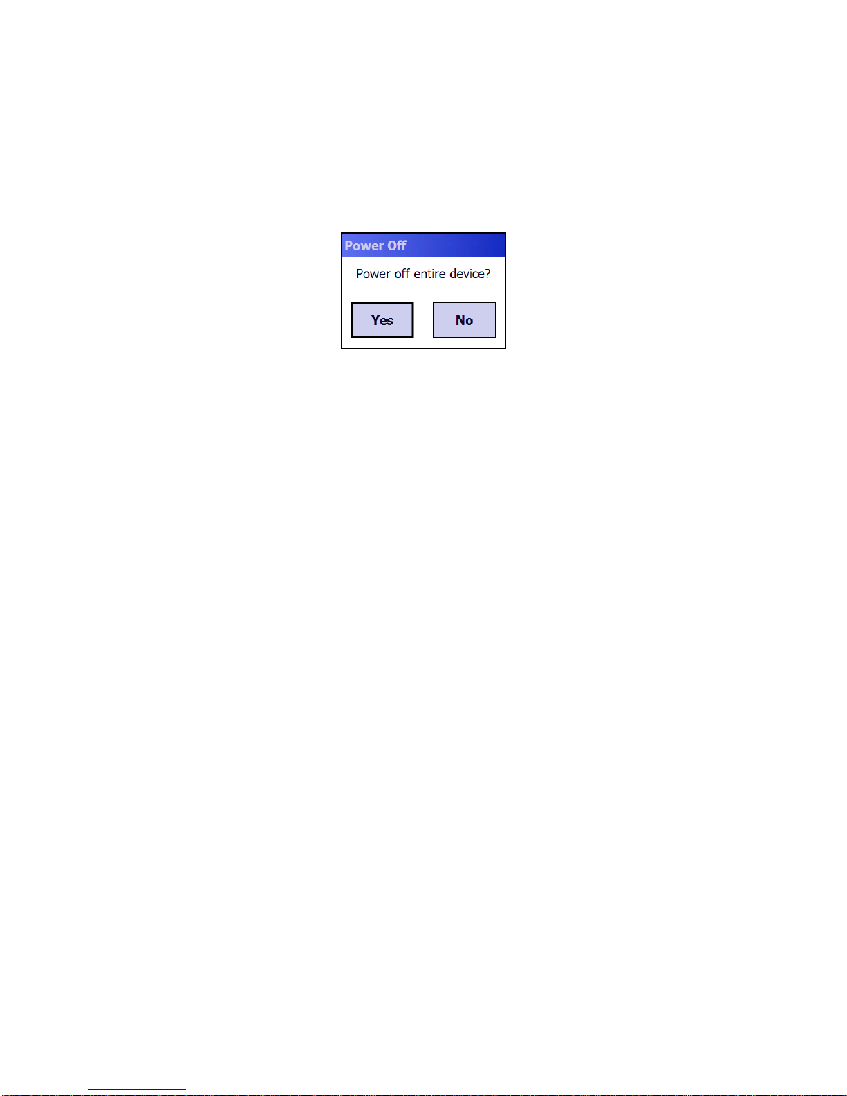
The user is given five seconds to respond. If the user selects "Yes", then the device
and all features are powered off. If the user selects "No", or does not respond within
five seconds, the device will power off, but leave features as they were.
The term "device off" here refers to a condition where the display is off and the
device appears unpowered. The device CPU may in fact be powered on.
In this condition the power consumption can be relevant and battery can be
completely discharged in some hours.
Page 96

1.12 DATALOGIC DESKTOP UTILITY
Datalogic Desktop Utility (DDU) allows Datalogic Windows administrators to
configure Windows CE and Embedded Handheld devices to control in dividual user
access. This includes:
• Prevent users from changing yo ur device OS settings.
• Use Application Selector to replace desktop with a selection of authorized
applications.
• Internet Explorer access restr iction, configuration and customized error recovery
mechanisms.
• Create quick access hot keys and configure trigger actions.
To open the DDU for the first time, tap Start > Settings > System > Datalogic Desktop
Utility or Start > Device tools > Datalogic Desktop Utility.
You can also get into DDU by pressing Alt-6.
You can use DL Buttons to associate specific keys, such as <F1>-<F10>, with
specific applications (see par. 1.6.3).
The “Alt + 6” is the button initially assigned to Datalogic Desktop Utility.
If you wish to assign this key to a different function, you must first select an
unassigned Button and assign it to the function – “Datalogic Desktop Utility”. You ca n
then go back and reassign the Button to something else.
Page 97

1.12.1 Administrative Options (Admin tab)
When you open the DDU control panel, the “Admin” tab appears.
COMMAND DESCRIPTION
Enable Datalogic Desktop Select/tap this checkbox to activate the DDU functions
such as Windows Access Restrictions and Application
Selector.
Enter Password Enter a password in the text box. This allows the user to
specify a password when this utility is launched. By
default the password is “1234”. A password can consist
of all standard keyboard characters.
Re-Enter Password Carefully re-enter the password in the second text box.
Set Password Select/tap “Set Password” to enable the password.
To change or remove the password, enter a new value,
re-enter the new value, and select/tap “Set Password”.
Set Defaults Select/tap “Set Defaults” to reset the default values of
all the functions on all the tabs. After you select this
option, you will receive a prompt to verify this selection.
Page 98

Setting a Password
To set a password:
1. Enter a password in the field. This allows the user to specify a password when
this utility is launched. By default the password is “1234”.
Be sure to record the Password for future reference.
NOTE
2. Re-enter the password in the second field.
3. Select/tap “Set Password” to enable the password.
4. Select/tap “OK” to close the “Set Password Confirmation” dialog.
You must select/tap “Set Password” prior to exiting DDU in order to
store and activate your new password. It is not necessary to select
“Enable Datalogic Desktop”.
NOTE
If you select/tap “Set Defaults” it will remove all custom settings and
restore all the factory default settings, except a previously set
password.
CAUTION
Changing a Password
To change to a new password:
1. Enter a new value in the “Enter Password field”.
2. Re-enter the new value in the “Re-enter Password” field.
3. Select/tap “Set Password”.
Page 99

Removing a Password
To remove a password:
1. Enter blanks in both “Password” fields.
2. Select/tap “Set Password”.
Password Request Dialog Box
Once the password is set, the next time you open the “Datalogic Desktop Utilit y”, the
DDU Password dialog box opens.
This dialog box will only open if a password was defined.
1. Type in your password using either the keypad on the unit, or using the stylus on
the soft input panel (SIP).
If you enter an incorrect password, the system will prompt you to input the correct one.
2. Select/tap “OK” to verify the password. Or tap “X” to cancel.
Page 100

1.12.2 WebAppLock Options (WebAppLoc tab)
Tap the "WebAppLocK” tab to access the WebAppLock Configuration options.
Error Page Redirection
Use the Error Redirection option to provide customized recovery from common errors.
When an error occurs, the browser can redirect access to a specified error page with
instructions on how to recover from the problem.
WebAppLock Configuration Tab WebAppLock Window Features
Error Redirection options
Error Type The “Error Type” pull-down list displays available Error Types:
(400) Invalid Syntax, (403) Request Forbidden, (404) Object Not
Found, (406) No Response Format, (410) Page Doesn't Exist, (500)
Internal Server Error, (501) Server Can't Do That, Generic Error,
Network Disconnected
Error Page Edit this textbox to associate a website or html file with the specified
error.
 Loading...