

Page 1
GWY-01-PBS-01
Reference Manual
Page 2

Datalogic Automation Srl
Via S. Vitalino, 13
40012 - Lippo di Calderara di Reno
Bologna - Italy
GWY-01-PBS-01 Reference Manual
Ed.: 02/2010
© 2010 Datalogic Automation S.r.l. ALL RIGHTS RESERVED. Protected to the fullest extent under
U.S. and international laws. Copying, or altering of this document is prohibited without express written
consent from Datalogic Automation S.r.l.
Datalogic and the Datalogic logo are registered trademarks of Datalogic S.p.A. in many countries,
including the U.S.A. and the E.U.
Subnet16 and Cobalt Dashboard are trademarks of Datalogic Automation S.r.l. All other brand and
product names mentioned herein are for identification purposes only and may be trademarks or
registered trademarks of their respective owners.
Datalogic shall not be liable for technical or editorial errors or omissions contained herein, nor for
incidental or consequential damages resulting from the use of this material.
26/02/10
Page 3

iii
CONTENTS
REFERENCES ............................................................................................................vi
Conventions................................................................................................................. vi
Reference Documentation........................................................................................... vi
Services and Support .................................................................................................. vi
SAFETY AND COMPLIANCE NOTICES................................................................... vii
FCC Compliance .........................................................................................................vii
Power Supply...............................................................................................................vii
CE Compliance............................................................................................................vii
GENERAL VIEW.......................................................................................................viii
1 GETTING STARTED....................................................................................................1
1.1 Introduction...................................................................................................................1
1.1.1 The Subnet16™ Gateway ............................................................................................1
1.2 Subnet16 Profibus Gateway Features..........................................................................1
1.3 About this Manual.........................................................................................................2
1.3.1 Who Should Read This Manual?..................................................................................2
1.3.2 HEX Notation................................................................................................................2
1.4 Gateway Dimensions....................................................................................................3
1.5 Installation Guidelines...................................................................................................4
1.5.1 Hardware Requirements...............................................................................................4
1.5.2 Installation Precautions.................................................................................................4
1.5.3 Network & Power Considerations.................................................................................4
1.5.4 Maximum Supported Trunk and Drop Cable Lengths ..................................................5
1.6 Installing the Gateway ..................................................................................................5
1.7 Additional Application Specific Configuration ...............................................................6
1.8 USB Driver Installation..................................................................................................7
1.9 Gateway Profibus Configuration using Cobalt Dashboard™......................................11
2 GATEWAY OVERVIEW ............................................................................................. 13
2.1 Operating Modes ........................................................................................................13
2.1.1 Subnet16™.................................................................................................................13
2.2 LED Indicators ............................................................................................................14
2.2.1 Front Panel LEDs .......................................................................................................14
2.3 External Connectors ...................................................................................................14
2.3.1 Profibus.......................................................................................................................15
2.3.2 USB ............................................................................................................................15
2.3.3 Subnet16™ RS485.....................................................................................................16
2.4 Power & Wiring...........................................................................................................16
2.4.1 Power Requirements ..................................................................................................16
2.4.2 Total System Current Consumption............................................................................ 17
2.4.3 Cable Voltage Drop ....................................................................................................17
2.4.4 Current Rating for Cables...........................................................................................18
2.5 Node ID Configuration & Management.......................................................................18
2.6 Gateway and Subnet Node Naming ...........................................................................19
2.7 Configuration Tools.....................................................................................................20
2.7.1 Cobalt Dashboard™ ...................................................................................................20
2.7.2 C-Macro Builder™ ......................................................................................................21
3 RFID COMMAND MACROS ......................................................................................22
Page 4

iv
3.1 What are RFID Command Macros? ...........................................................................22
3.2 Why use macros?.......................................................................................................22
3.3 What can macros do?.................................................................................................22
3.4 What is a macro trigger?.............................................................................................22
3.5 How are macros created?...........................................................................................23
3.6 Which communication interfaces support the use of macros? ...................................23
3.7 What happens to existing Macros if a controller must be replaced? ..........................23
3.8 How can I learn more about the Dashboard and C-Macro Builder? ........................... 23
4 COMMAND PROTOCOL ...........................................................................................24
4.1 CBx Command Protocol Overview .............................................................................24
4.2 CBx - Command Packet Structure.............................................................................. 25
4.3 CBx - Response Packet Structure..............................................................................26
4.3.1 Instance Counter ........................................................................................................26
4.4 CBx Commands Table................................................................................................27
4.5 CBx Command Protocol Examples ............................................................................29
4.5.1 CBx - Controller Command Example.......................................................................... 29
4.5.2 CBx - Controller Response Example .......................................................................... 30
4.5.3 CBx - Gateway Command Example ........................................................................... 30
4.5.4 CBx - Gateway Response Example ...........................................................................31
4.6 Node Status Byte Definition Table..............................................................................32
4.7 CBx Error Response Packet Structure .......................................................................33
4.8 CBx Error Code Table ................................................................................................34
4.9 CBx - Error Response Example..................................................................................35
4.10 Notification Messages.................................................................................................36
4.10.1 Notification Message Table ........................................................................................ 37
4.10.2 Notification Mask Example .........................................................................................37
4.10.3 Notification Message Packet Structure.......................................................................38
5 PROFIBUS INTERFACE............................................................................................ 39
5.1 Profibus Overview.......................................................................................................39
5.2 Profibus-DP ................................................................................................................39
5.3 Data Exchange ...........................................................................................................40
5.4 Protocol Implementation.............................................................................................41
5.4.1 Definitions...................................................................................................................41
5.4.2 Control Field ...............................................................................................................42
5.4.3 SAP Field....................................................................................................................45
5.4.4 Length Field................................................................................................................45
5.4.5 Application Data Buffer...............................................................................................46
5.5 Examples of Profibus Command/Response Mechanism............................................ 46
5.5.1 Example 1: Normal Command/Response Sequence .................................................48
5.5.2 Example 2: Unsolicited Responses (Continuous Read Mode) ...................................58
5.5.3 Example 3: Fragmentation of Responses................................................................... 62
5.5.4 Example 4: Fragmentation of Commands ..................................................................71
5.5.5 Example 5: Resynchronization ...................................................................................82
6 TECHNICAL FEATURES........................................................................................... 87
A MODELS AND ACCESSORIES ................................................................................88
Datalogic Automation RFID Tags ...............................................................................89
B EXAMPLE NETWORK LAYOUTS............................................................................. 90
Subnet16™ Gateway –ThickNet Network Layout ......................................................90
Subnet16™ Gateway –ThinNet Network Layout ........................................................ 91
Page 5

v
C
ASCII CHART.............................................................................................................92
Page 6

vi
REFERENCES
CONVENTIONS
This manual uses the following conventions:
“User” or “Operator” refers to anyone using a GWY-01-PBS-01.
“Device” refers to the GWY-01-PBS-01.
“You” refers to the System Administrator or Technical Support person using this manual to
install, mount, operate, maintain or troubleshoot a GWY-01-PBS-01.
Throughout this manual, the GWY-01-PBS-01 is referred to as the “Subnet16 Gateway” or
simply “the Gateway”.
Cobalt C-Series, HF-Series and UHF-Series RFID Controllers are referred to as Cobalt
Controllers, or just “the Controller”.
In addition, the terms “Subnet Node Number”, “Node ID” and “Controller ID” are used
interchangeably.
REFERENCE DOCUMENTATION
The documentation related to the GWY-01-PBS-01 management is available at the website:
www.automation.datalogic.com
SERVICES AND SUPPORT
Datalogic provides several services as well as technical support through its website. Log on
to www.automation.datalogic.com and click on the
UlinksU indicated for further information
including:
PRODUCTS
Search through the links to arrive at your product page where you can download specific
Manuals
and Software & Utilities including:
- Cobalt Dashboard™ a Windows-based application that provides users with complete
control over their Datalogic Automation RFID hardware. Users can monitor their entire
RFID infrastructure - from the tag level, to the RFID controller, to the Gateway and to
the Host. It provides device configuration through serial and TCP/IP interfaces
depending on the device type.
- C-Macro Builder™ is an easy to use GUI-driven utility for Windows. This software tool
allows users with minimal programming experience to “build” their own macro programs
(which are stored internally on and executed directly by Cobalt RFID Controllers).
SERVICES & SUPPORT
- Datalogic Services
- Warranty Extensions and Maintenance Agreements
- Authorised Repair Centres
CONTACT US
E-mail form and listing of Datalogic Subsidiaries
Page 7

vii
SAFETY AND COMPLIANCE NOTICES
FCC COMPLIANCE
Modifications or changes to this equipment without the expressed written approval of
Datalogic could void the authority to use the equipment.
This device complies with PART 15 of the FCC Rules. Operation is subject to the following
two conditions: (1) This device may not cause harmful interference, and (2) this device must
accept any interference received, including interference which may cause undesired
operation.
This equipment has been tested and found to comply with the limits for a Class A digital
device, pursuant to part 15 of the FCC Rules. These limits are designed to provide
reasonable protection against harmful interference when the equipment is operated in a
commercial environment. This equipment generates, uses, and can radiate radio frequency
energy and, if not installed and used in accordance with the instruction manual, may cause
harmful interference to radio communications. Operation of this equipment in a residential
area is likely to cause harmful interference in which case the user will be required to correct
the interference at his own expense.
POWER SUPPLY
This product is intended to be installed by Qualified Personnel only.
This device is intended to be supplied by a UL Listed or CSA Certified Power Unit with
«Class 2» or LPS power source.
CE COMPLIANCE
Warning:
This is a Class A product. In a domestic environment this product may cause radio
interference in which case the user may be required to take adequate measures.
Page 8
viii
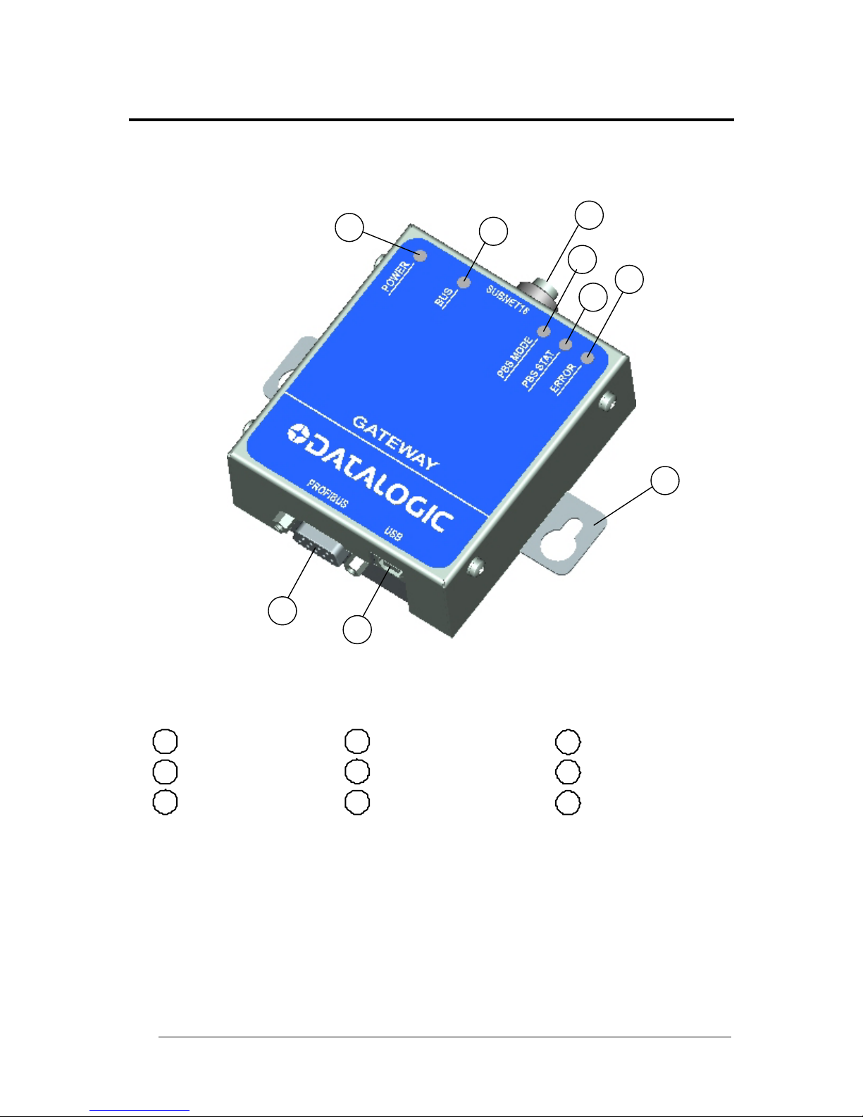
GENERAL VIEW
GWY-01-PBS-01
Figure A
1
2
3
6
5
Power On LED
Subnet 16 Co nnecto
r
Profibus Status LED
Configuration Error LED
4
Profibus Mode LED
Subnet 16 BUS LED
9
8
US B Con nector
Profibus Conn ector
7
Mounting Bracket
3
1
4
7
8
2
5
6
9
Page 9

GETTING STARTED
1
1
1 GETTING STARTED
1.1 INTRODUCTION
Welcome to the GWY-01-PBS-01 Reference Manual. This manual will assist you in the
installation, configuration and operation of Datalogic Automation Subnet16™ Profibus
Gateway Interface Module.
The Profibus Gateway can control up to 16 passive ultra-high or high frequency read/write
Radio-Frequency Identification (RFID) controllers. In order to meet and exceed the
requirements of the industrial automation industry, the Profibus Gateway and Datalogic
Automation RFID controllers are designed to be compact, reliable and rugged.
1.1.1 The Subnet16™ Gateway
Subnet16™ is a 16-Node Multidrop bus architecture and protocol that provides connectivity
for up to 16 RFID controllers through a single Gateway device.
The Profibus Gateway supports Profibus -DP communications and can be connected to a
Programmable Logic Controller (PLC) via Profibus compatible cabling. It’s compatible with
Datalogic Automation Cobalt UHF-Series, HF-Series and C-Series RFID controllers, reading
LRP, HMS and T-Series RFID tags.
1.2 SUBNET16 PROFIBUS GATEWAY FEATURES
Multi-Drop capable; controls up to 16 RFID reader/writers, each functioning
independently and simultaneously.
Operational power is supplied directly from the Subnet 16™ network
Small footprint provides ease of mounting (104 x 107 x 32 mm).
Galvanically isolated Profibus interface with auto baud rate detection 9.6 kbit/s - 12
Mbit/s
Selectable Profibus node addressing (0 to 128), default is 63
LED status indicators for Power/Ready, Subnet16 bus activity, Profibus mode,
Profibus network status, Configuration error indication
Supports controller macro functionality
Flash memory for software updates
Real-time Calendar/Date functions
Auto configuration of RFID controllers, automatic Node ID number assignment
Node Fault Detection
Isolated bus interfaces
Page 10

GWY-01-PBS-01
2
1
1.3 ABOUT THIS MANUAL
This manual provides guidelines and instructions for installing, configuring and operating
Datalogic Automation's Subnet16 Profibus Gateway Interface Module (GWY-01-PBS-01).
This document does NOT include explicit details regarding each of the Gateway’s RFID
commands. Specific RFID command related information is available in the CBx Command
Protocol – Reference Manual, which is available at www.automation.datalogic.com.
However, this manual does explain the process of issuing commands from a host PC or
Programmable Logic Controller (PLC) to a Subnet16 Gateway, Subnet network and attached
RFID controllers.
1.3.1 Who Should Read This Manual?
This manual should be read by those who will be installing, configuring and operating the
Gateway. This may include the following people:
Hardware Installers
System Integrators
Project Managers
IT Personnel
System and Database Administrators
Software Application Engineers
Service and Maintenance Engineers
1.3.2 HEX Notation
Throughout this manual, numbers expressed in Hexadecimal notation are prefaced with “0x”.
For example, the number "10" in decimal is expressed as "0x0A" in hexadecimal. See
Appendix C for a chart containing Hex values, ASCII characters and their corresponding
decimal integers.
Page 11
GETTING STARTED
3
1
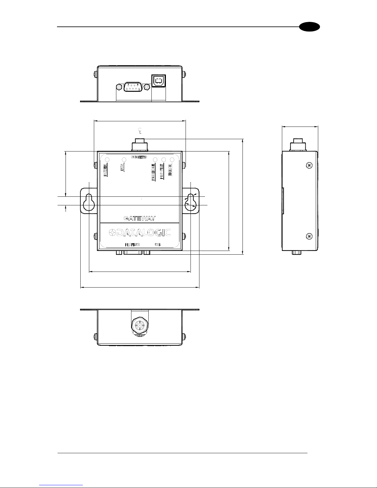
1.4 GATEWAY DIMENSIONS
82
[3.24]
104
[4.08]
89
[3.50]
40.7
[1.60]
7.6
[0.30]
91.4
[3.60]
107
[4.20]
32
[1.27]
Ø5.0
[Ø0.20]
Ø10.2
[Ø0.40]
N° 2
N° 2
Figure 1: GWY-01-PBS-01 Dimensions
Page 12
GWY-01-PBS-01
4
1
1.5 INSTALLATION GUIDELINES
1.5.1 Hardware Requirements
The following components are required for a complete Subnet16 RFID system:
One Subnet16 Profibus Gateway Interface Module
One Profibus-capable host; Programmable Logic Controller (PLC) or PC
One to 16 RFID controllers (Cobalt C-Series, HF-Series or UHF-Series Controllers -
RS485 models)
Adequate length cabling, connectors and terminators
Sufficient power, supplied via Subnet16 network cabling, capable of powering the
Gateway and its RFID controllers
Datalogic Automation RFID series tags: HMS, LRP, T/Gamma, I, or UHF-G2-525
1.5.2 Installation Precautions
Do not route cables near unshielded cables or near wiring carrying high voltage or
high current. Cross cables at perpendicular intersections and avoid routing cables
near motors and solenoids.
Review the power requirements of your RFID network and provide a suitable power
supply.
Avoid mounting the controller near sources of EMI (electro-magnetic interference) or
near devices that generate high ESD (electro-static discharge) levels. Always use
adequate ESD prevention measures to dissipate potentially high voltages.
If electrical interference is encountered (as indicated by a significant reduction in
read/write performance), relocate the controller to an area free from potential sources
of interference.
Perform a test phase by constructing a small scale, independent network that
includes only the essential devices required to test your RFID application (use
Datalogic Automation approved Subnet16™ cables and accessories).
1.5.3 Network & Power Considerations
Refer to the network diagrams in Appendix B. Choose the network architecture
(ThickNet vs. ThinNet) that best suits your RFID requirements.
Construct your chosen network using only Datalogic Automation approved
Subnet16™ cables, Drop-T connectors, Terminating Resistors and accessories.
Review the power requirements of your RFID network and provide a suitable power
supply. (See Appendix A for power supplies offered by Datalogic Automation).
NOTE
It is recommended that power be applied directly to the Subnet16™ Network
trunk and distributed through drop cables to the Gateway and RFID
controllers. By positioning the power supply near the middle of the network
(see examples), you can limit voltage drop at the ends.
Page 13

GETTING STARTED
5
1
1.5.4 Maximum Supported Trunk and Drop Cable Lengths
ThickNet trunk length up to 300 m.
ThinNet trunk length up to 20 m.
ThinNet drop cable length up to 2 m.
1.6 INSTALLING THE GATEWAY
The numbered steps in the following procedure are also indicated in the SubNet16 networks
example layouts shown in Appendix B.
1. Preliminary Notes: Read the Installation Guidelines in par. 1.5.
2. Mounting: Mount the Gateway to your chosen location using two M5 (#10) screws,
lock washers and nuts. The Gateway may be mounted in any orientation, but should
be aligned in such a manner that the LED indicators can be seen during operation.
3. Gateway Connection: Attach one end of a 5-pin, male-to-male, M12, ThinNet drop
cable (P/N: CBL-1481-XX) to the 5-pin, female, M12 connector on the Gateway.
Connect the other end of this 5-pin, male-to-male, M12, ThinNet drop cable to the 5pin, female, M12 connector on EITHER a ThickNet to ThinNet Drop-T Connector
OR a ThinNet to ThinNet Drop-T Connector (as per your network and RFID
application requirements).
4. Trunk Wiring: Attach one end of a male-to-female trunk cable to each mating
connector on the Drop-T Connector. Continue connecting trunk cables and Drop-T
connectors as needed.
Note: trunk length should not exceed 300 m for ThickNet and 20 m for ThinNet.
5. RFID Controller Connection: Connect the male end of a 5-pin, male-to-female,
ThinNet drop cable to the female end on your Drop-T connector(s). Attach the
remaining female end of the ThinNet drop cable to the 5-pin, male, M12 connector on
a Cobalt UHF, Cobalt HF or C-Series Controller (RS485 models). Repeat Step 5
for each RFID controller you plan to install.
Note: maximum drop cable length is 2 m.
6. Termination Resistors: For ThickNet Networks: Connect a Terminating Resistor
(P/N: CBL-1489, male) or (P/N: CBL-1497, female) to the first and last Drop-T
Connector on the trunk line.
For ThinNet Networks: Connect a Terminating Resistor (P/N: CBL-1490, male) or
(P/N: CBL-1496, female) to the first and last Drop-T Connector on the trunk line.
7. Power Supply Wiring: For ThickNet Networks: Using a 5-pin, female, 7/8 - 16,
ThickNet to Bare Wire Leads cable (P/N: CBL-1495-XX), connect the bare wires to
your power supply (SHIELD wire connected to Earth). Attach the female, ThickNet
end to the 5-pin, male, ThickNet end on a Drop-T connector (P/N: CBL-1526).
For ThinNet Networks: Using a 5-pin, female, M12, ThinNet to Bare Wire Leads cable
(P/N: CBL-1494-XX), connect the bare wires to your power supply (SHIELD wire
connected to Earth). Attach the female, ThinNet end to the 5-pin, male, ThinNet end
on a Drop-T connector (P/N: CBL-1486).
Page 14
GWY-01-PBS-01
6
1
8. Host Connection: Connect the Gateway to the Profibus network via a Profibus-
compatible interface cable. Turn the power supply ON.
The POWER LED on the Gateway will remain lit while power is applied to the unit.
After the boot process is complete, the PBS Mode LED will also light up to indicate
the Gateway Profibus mode. It may appear green or red (solid or flashing) depending
on the status of the connection with your Profibus network (see par. 2.2 for the
behavior of the Gateway’s Profibus Mode LED).
9. Automatically Configure Subset16™ Node IDs: At this point all controllers are
powered and should have Node IDs set to 00, (all controller Node LEDs
= OFF), and
Subnet16™ baudrate = 9600 (factory defaults).
a. Place the RFID Controller Configuration Tag in front of an RFID Controller (the
controller's red RF Activity LED blinks once indicating the tag has been read), and
wait for the Gateway to assign a valid Node ID to it. The controller's Node LEDs
now indicate a valid Node ID. Remove the Configuration Tag from the controller.
b. Repeat this step for each node in the Subnet16™ network (one controller at a
time). The first is Node ID 1, then 2 and so on up to 16 (binary).
The Subnet16™ network is now configured with the default values and can communicate
with the Gateway Profibus which in turn communicates with the Master Profibus.
GWY-01-PBS-01 PROFIBUS FACTORY DEFAULTS
Node Address: 63
Input and Output Buffer size: 64 bytes
1.7 ADDITIONAL APPLICATION SPECIFIC CONFIGURATION
To modify the Gateway’s internal configuration for application specific requirements:
1. Install the USB Driver onto the configuration PC, see par. 1.8.
2. Download the Cobalt Dashboard™ utility from www.automation.datalogic.com and
install the software on your configuration computer. Use the Dashboard utility to
connect, via USB, to the Gateway. You will then be able to use the Cobalt Dashboard
Utility to configure the Gateway and send RFID commands for testing purposes. See
par. 1.9.
Page 15
GETTING STARTED
7
1
1.8 USB DRIVER INSTALLATION
This paragraph contains instructions for installing the Windows 2000/XP USB driver for
Datalogic Automation RFID devices. Complete the following steps before installing the RFID
USB driver.
1. Download the RFID USB driver package from www.automation.datalogic.com.
2. Extract the driver files to a separate folder on your host computers’ Desktop.
3. Connect the USB interface cable (and power supply, if applicable) as described in the
Installation Guide included with your RFID product.
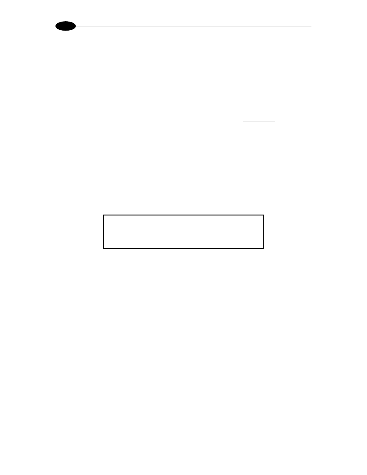
4. Apply power to your RFID device. Windows should detect the new hardware and start
the Found New Hardware Wizard. If it does not, run the Add Hardware applet in
Windows’ Control Panel.
Figure 2: Found New Hardware Wizard – Do Not Connect to Windows Update
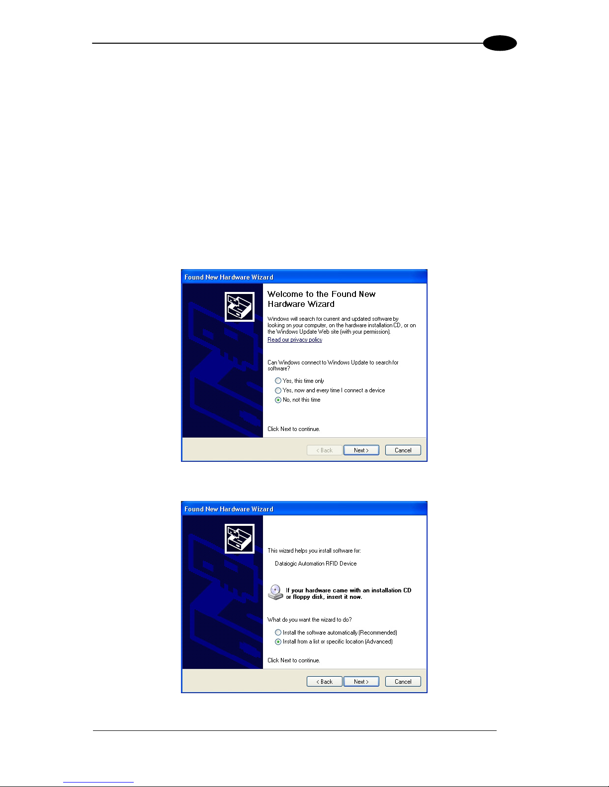
Figure 3: Found New Hardware Wizard – Install From List
Page 16
GWY-01-PBS-01
8
1
5. Select “Install from a list or specific location” and then click Next.
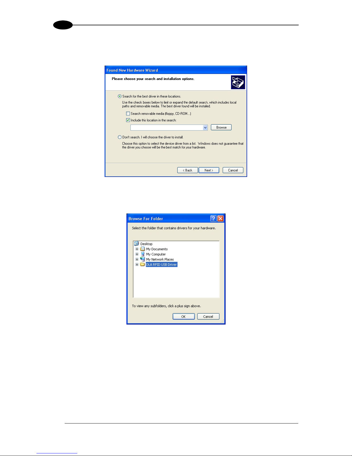
6. Check the box labeled: “Include this location in the search” and then click the Browse
button.
Figure 4: Found New Hardware Wizard – Include this Location
7. Browse to the folder containing the extracted RFID USB driver files and then click OK.
Figure 5: Found New Hardware Wizard - Browse for Folder
Page 17
GETTING STARTED
9
1
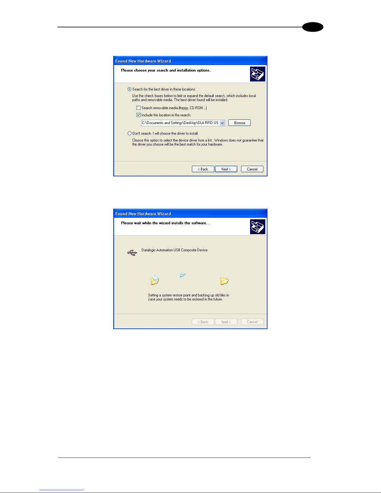
8. Click Next to install the USB driver.
Figure 6: Found New Hardware Wizard – Ready to Install
Please wait while the Found New Hardware Wizard installs the USB driver.
Figure 7: Installing the USB Driver
Page 18
GWY-01-PBS-01
10
1
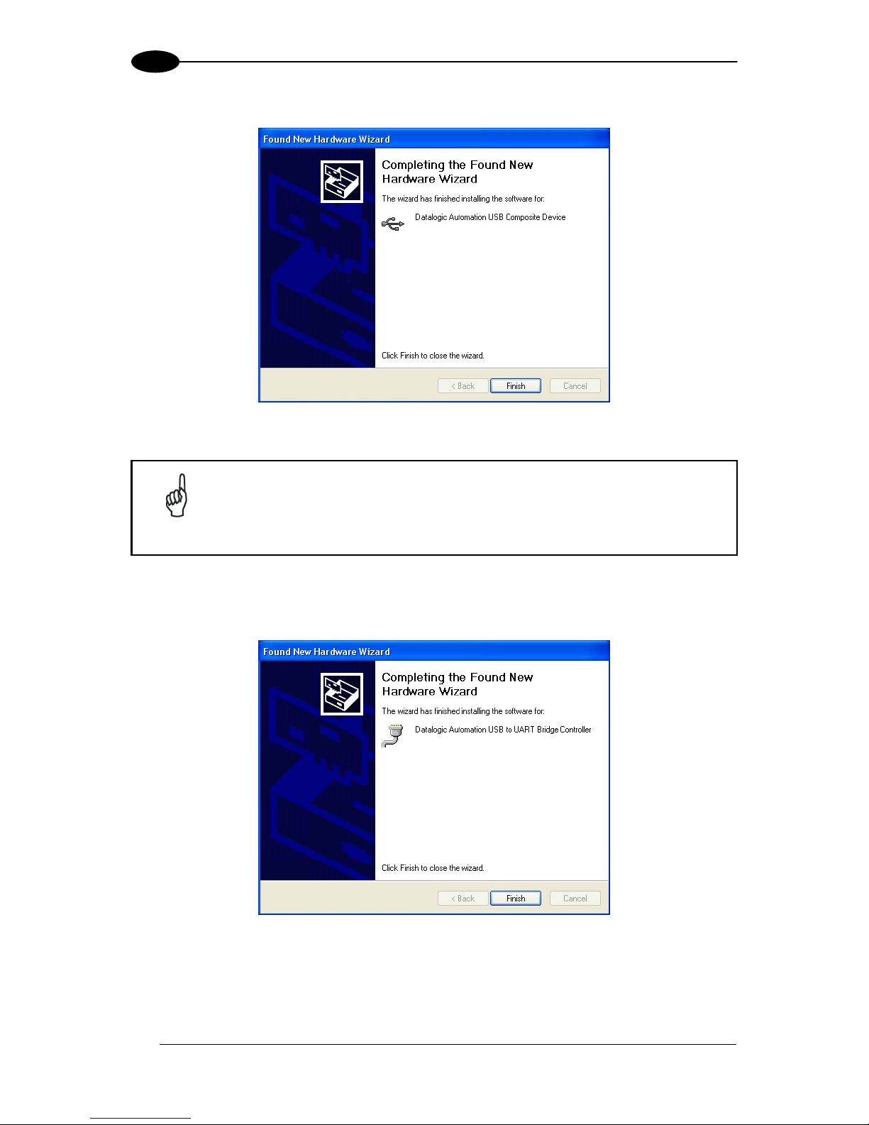
9. After the USB driver has been installed, click Finish.
Figure 8: USB Driver Installation Complete
NOTE
Immediately after you click Finish, the Found New Hardware Wizard will
close and then automatically restart, prompting you to repeat the USB driver
installation. This occurs because Windows requires a second trip through
the installation routine to install and configure a virtual COM port for use by
the RFID USB device.
10. Repeat Steps 5-9 to install the virtual COM port and complete the installation of the
RFID USB driver.
Figure 9: Virtual COM Port USB Driver Installation Complete
Page 19
GETTING STARTED
11
1
1.9 GATEWAY PROFIBUS CONFIGURATION USING COBALT
DASHBOARD™
The Cobalt Dashboard™ Utility is a software application that allows users to view, modify,
save and update the configuration settings of their Cobalt controllers. Follow the instructions
below to operate the Cobalt Dashboard Utility and to set the Cobalt device’s configuration.
1. Install the Gateway as described in par. 1.6.
2. Install the Cobalt USB driver to your PC as described in par. 1.8.
3. Connect the Gateway to your PC through the USB interface, power the network and
wait for the boot procedure to finish.
4. Run the Cobalt Dashboard™.
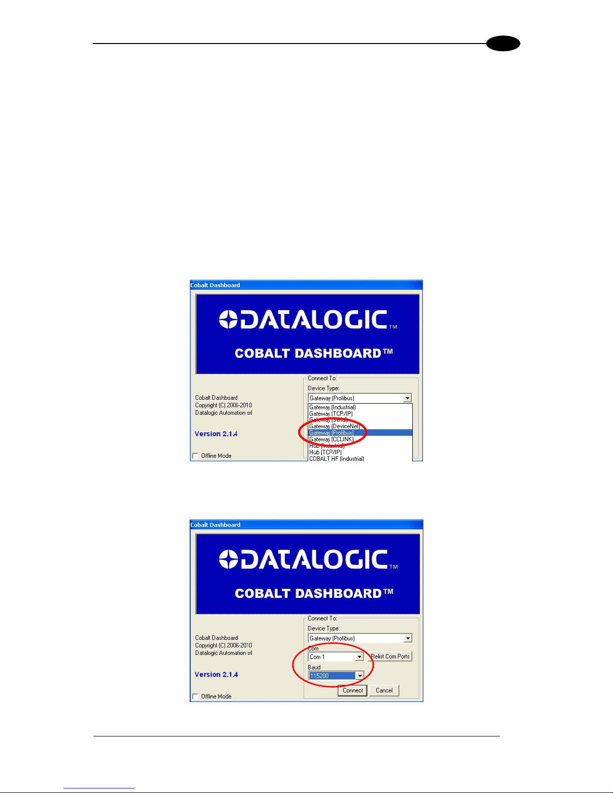
5. From the Connection screen, choose “Gateway Profibus”.
Figure 10: Cobalt Dashboard™ Gateway Profibus Selection
6. Choose the appropriate COM port and select 115200 Baud (this is the default serial
baud rate for USB connection); click “Connect”.
Figure 11: Cobalt Dashboard™ COM and Baudrate Selection
Page 20
GWY-01-PBS-01
12
1
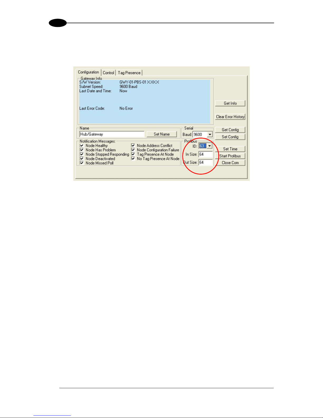
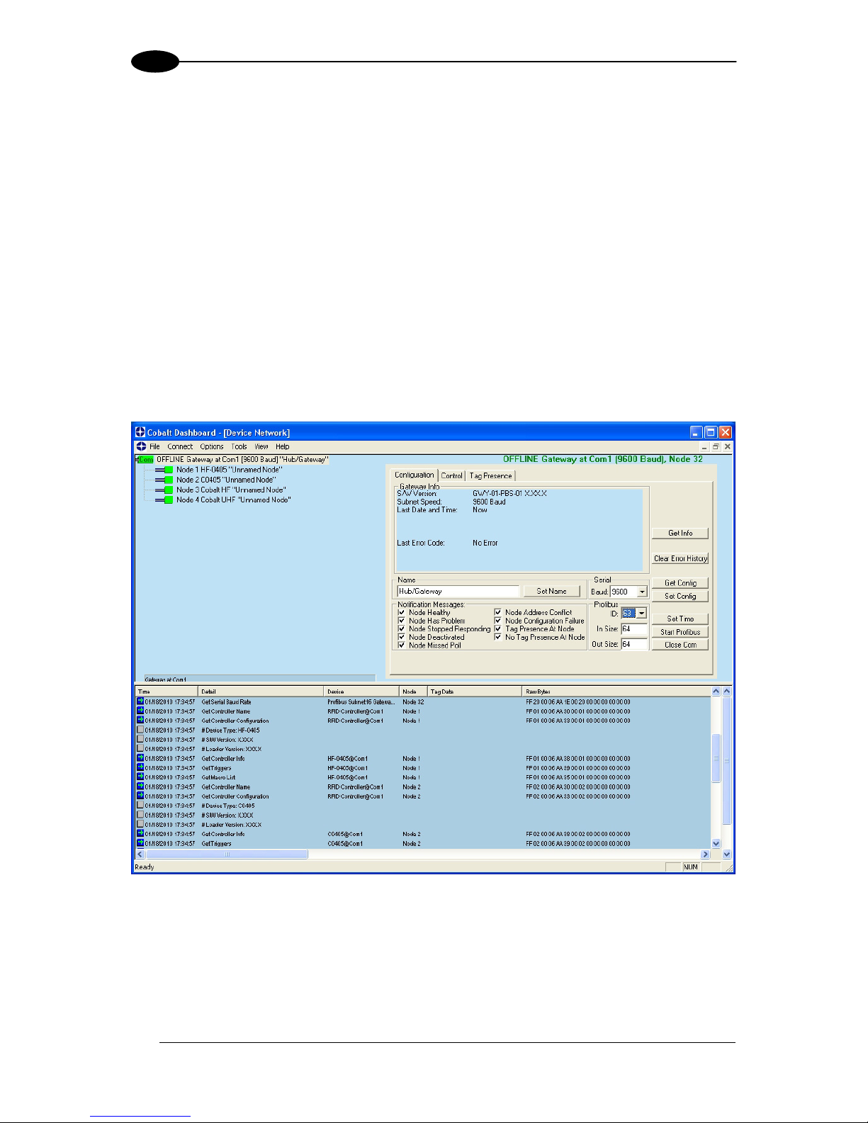
The Dashboard should send some commands to retrieve device and configuration
information from the device. If serial communications are set up correctly, the device
configuration area within the Cobalt Dashboard should now look like this:
Figure 12: Cobalt Dashboard™ Gateway Profibus Device Configuration Area
The default Profibus ID is 63, and the default Input and Output Buffer sizes are 64 bytes
each.
To change the Profibus ID of the device, and/or the Input Buffer/Output Buffer sizes, enter
the desired values in the appropriate boxes in the configuration tab, and click “Set Config”.
For Profibus, the new ID and buffer sizes will not take effect until the device is reset one
more time, or the power is cycled. Turn the unit off and back on to use the new ID and buffer
size settings. For other settings (such as Tag Type, continuous read parameters, etc), the
unit does not need to be reset again or have the power cycled.
See the Cobalt Dashboard™ User's Manual for more configuration details.
Page 21
GATEWAY OVERVIEW
13
2
2 GATEWAY OVERVIEW
2.1 OPERATING MODES
2.1.1 Subnet16™
Subnet16™ is an advanced feature-rich network protocol that supports a subset of the
Datalogic Automation MUX32 legacy protocol. The advanced features implemented in the
Subnet16 protocol allow the Gateway to assign individual Node ID values automatically to
each RFID controller connected on the Subnet bus. Subnet16 also allows the Gateway to
detect when a new controller is connected to the Subnet or when a controller “falls off the
bus” (stops responding).
Through the Subnet16 protocol, the Gateway is able to store a backup copy of each RFID
controller’s custom configuration settings. In the event that an RFID controller fails, the
stored configuration settings can be automatically reassigned to a replacement RFID
controller.
Real-time clock functionality is supported in Subnet16 mode. Host-bound data packets are
automatically Time/Date stamped as they pass through the Gateway and on to the host.
NOTE
The Gateway communicates over the RS485 physical layer using Subnet16,
but it is not a generic RS485 device. RS485 cabling requirements are
however the same.
Page 22
GWY-01-PBS-01
14
2
2.2 LED INDICATORS
2.2.1 Front Panel LEDs
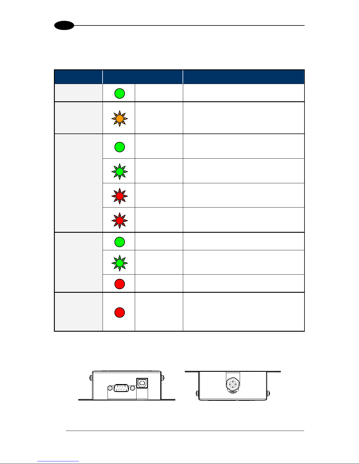
LED Name LED Color LED Description
POWER
GREEN
The POWER LED is ON whenever power
is applied to the Gateway.
BUS
AMBER
The BUS LED will flash ON and OFF to
indicate that data is being transmitted
between the Gateway and one or more
RFID controllers on the Subnet16 network.
SOLID GREEN
The Profibus Mode LED is solid green
when the Gateway Profibus interface is
operational, online and exchanging data.
FLASHING
GREEN
The Profibus Mode LED is flashing green
when the Gateway Profibus interface is
operational and on-line, but idle.
FLASHING RED
(1 FLASH)
The Profibus Mode LED is flashing red
and blinks once when a Profibus
parameterization error has occurred.
PBS MODE
Profibus Mode
FLASHING RED
(2 FLASHES)
The Profibus Mode LED is flashing red
and blinks twice when a Profibus
configuration error has occurred.
SOLID GREEN
The Status LED is solid green when the
Profibus communication is initialized.
FLASHING
GREEN
The Status LED is flashing green when the
Profibus communication is initialized, but a
diagnostic event(s) is present.
PBS STAT
Profibus Status
SOLID RED
The Status LED is solid red when a
Profibus exception error has occurred.
ERROR
SOLID RED
The Error LED is solid red when a
Gateway configuration error has occurred,
i.e. an invalid or unrecognized command.
This LED will be cleared when a valid
command is sent.
Table 1: Front Panel LEDs
2.3 EXTERNAL CONNECTORS
Figure 13: External Connectors
Page 23
GATEWAY OVERVIEW
15
2
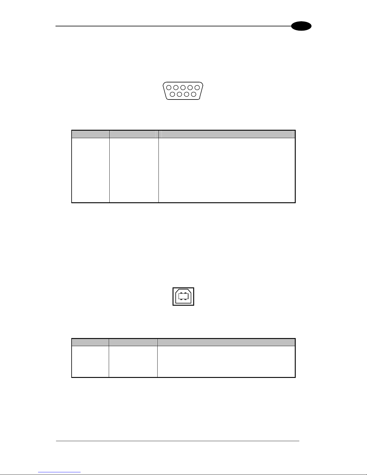
2.3.1 Profibus
The Gateway Profibus Connector is used for Profibus Slave Node connection to the Profibus
network.
5 1
69
Figure 14: Profibus DB9F Interface Connector
Pin Name Function
1 nc
2 nc
3 B Line (+) Positive RxD/TxD (RS485 level)
4 RTS Request To Send
5 GND Bus Ground (isolated)
6 +5 Vdc Bus Power
7 nc
8 A Line (-) Negative RxD/TxD (RS485 level)
9 nc
See par. 2.4 for more information regarding power and wiring for the Gateway.
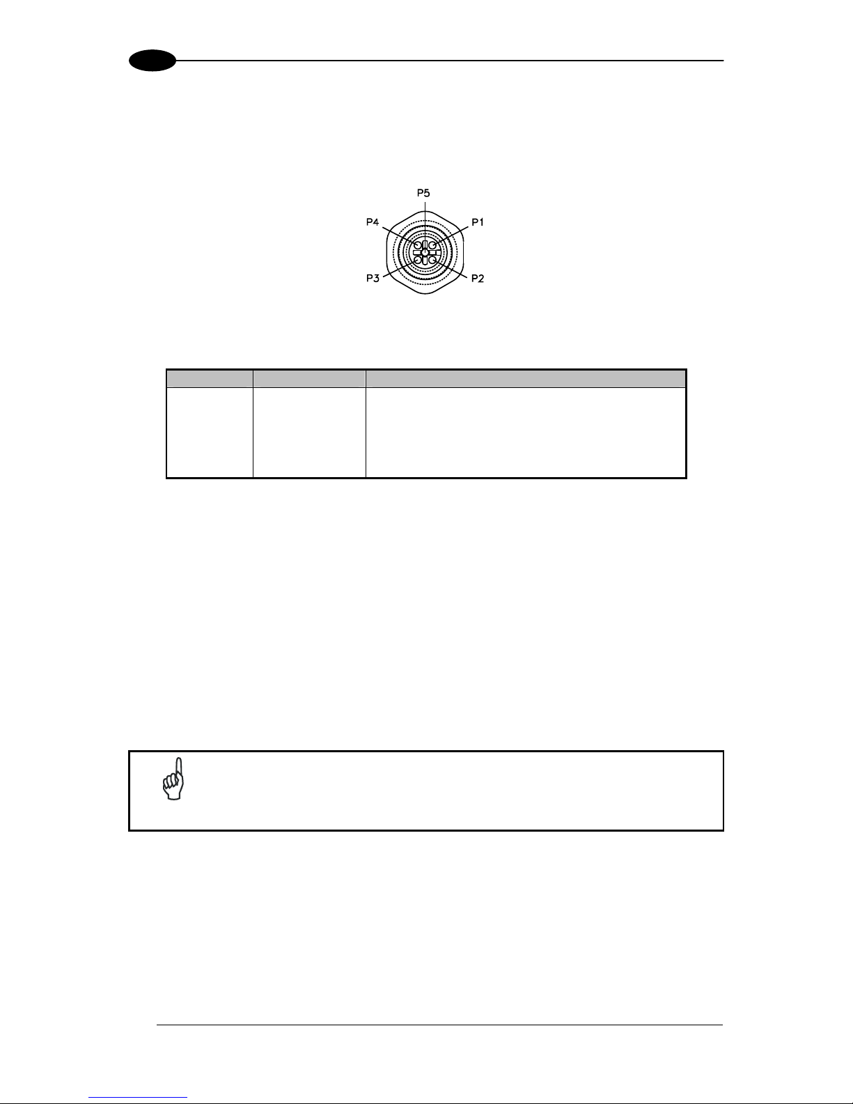
2.3.2 USB
The Gateway USB Connector (type B, female) is used for establishing a direct serial
connection with a host computer for the purpose of configuring the Gateway.
12
34
Figure 15: USB Type B Female Interface Connector
Pin Name Function
1
Vdc 5 + Vdc USB power source
2
D- Data -
3
D+ Data +
4
GND USB power source Ground
Page 24
GWY-01-PBS-01
16
2
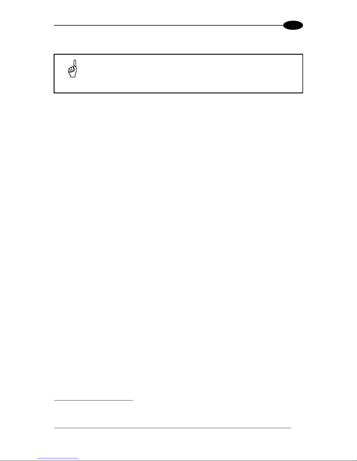
2.3.3 Subnet16™ RS485
The Gateway Subnet16™ RS485 Connector (M12 5PF) is used for connecting to the
Subnet16 network and RFID controllers.
Figure 16: M12 5PF Subnet16™ RS485 Interface Connector
Pin Name Function
1
Shield Cable shield
2
Vdc Power supply input voltage +
3
GND Power supply input voltage -
4
RTX+ RS485 Receive/Transmit Data +
5
RTX- RS485 Receive/Transmit Data -
2.4 POWER & WIRING
The information presented below is provided to assist the installer in determining the amount
of power that will be required by the Gateway and its Subnet network.
2.4.1 Power Requirements
The Gateway requires an electrical supply voltage of 12 to 30 Vdc. In addition, each RFID
controller connected to the Gateway via the Subnet16™ network will also require power. Use
a regulated power supply that is capable of delivering the requirements listed in the
Technical Features.
NOTE
Power is applied directly to the Subnet16™ Network trunk and distributed
through drop cables to the Gateway and RFID controllers. By positioning the
power supply near the middle of the network, you can limit voltage drop at
the ends, (see Appendix B for network layout diagrams).
The following information is provided to assist you in determining the power requirements of
your RFID application.
Page 25
GATEWAY OVERVIEW
17
2
2.4.2 Total System Current Consumption
NOTE
The current consumption values of each product are given in the Technical
Features paragraph of the relative Installation manual and refer to the min
and max input voltage range. These values already include an adequate
safety margin. The consumption values given in the following examples have
been interpolated for an input voltage of 24 Vdc.
Max Gateway Current: 200 mA @ 12 Vdc (133 mA @ 24 Vdc).
Max Controller Current: 366 mA @ 24 Vdc for Cobalt HF-Series, 87 mA @ 24 Vdc for
C0405-Series, etc. (refer to controller’s spec).
Calculating Total System Current Consumption:
Total System Current Consumption = [Max Gateway Current + (Max Controller Current x
Number of Controllers)]
Example
A Subnet16™ network powered at 24 Vdc is composed of a GWY-01-PBS-01 connecting
eight C0405-485 RFID Controllers.
Total System Current Consumption = [0.133 A + (0.087 A X 8)] = 0.829 A
2.4.3 Cable Voltage Drop
In addition, each RFID controller on the Subnet will experience a certain amount of voltage
drop depending on the length of the cable.
Cable Resistance per Meter
ThinNet = 0.058 ohms per meter per wire
ThickNet = 0.0105 ohms per meter per wire
Calculating Voltage Drop
Voltage Drop = (Max Controller Current x Number of Controllers) x (Cable Resistance per
Meter per Wire
1
x Cable length in Meters)
Example
A Subnet16™ network is composed of a GWY-01-PBS-01 connecting eight C0405-485 RFID
Controllers (87 mA each @ 24 Vdc). A total of 20 meters of ThinNet cables are used to
connect the devices, which have Cable Resistance = 0.058 Ohms per meter per wire. The
network power is 24 Vdc.
2
Voltage Drop = [0.133 A GWY + (0.087 A x 8 controllers)] x [(0.058 x 2) x 20 meters] =
1.92 Vdc
24 Vdc - 1.92 = 22.08 Vdc at controller number 8
1
The resistance calculation must include both wires (Vdc and GND).
2
This example assumes the power supply is placed at the end of the network, therefore controller #8 is the worst case. By
placing the power supply in the middle of the network the voltage drop at the ends is reduced.
Page 26
GWY-01-PBS-01
18
2
It is recommended that the voltage drop calculation be conducted on the RFID controller that
is farthest from the Gateway, as it will experience the greatest voltage drop.
2.4.4 Current Rating for Cables
The maximum current rating for the Subnet16™ network using Datalogic Automation's
cables and accessories (CBL-xxxx), is 4.0 A.
2.5 NODE ID CONFIGURATION & MANAGEMENT
Only RS485-based RFID controllers can be connected to a Gateway’s Subnet network and
each must be assigned a unique Node ID value between 1 and 16.
When an RFID controller is connected to the Gateway’s Subnet network, the Gateway will
query the new controller to obtain certain configuration values (specifically the Node ID
number). If the Gateway does not detect a Node ID conflict, it will “allow” the RFID controller
onto the Subnet network.
By using the Cobalt HF Configuration Tag that is included with each RS485-based Cobalt
and HF-Series RFID Controller, or the Cobalt UHF Configuration Tag that is included with
each RS485-based Cobalt UHF-Series RFID Controller, the Node ID value can be
dynamically assigned by the Gateway or can be manually assigned by the user.
For the Gateway to dynamically assign a Node ID value to a controller, the controller must
first be initialized with the Node ID value of zero. This is the equivalent of having no Node ID
assigned.
NOTE
All Datalogic Automation RS485-based controllers ship with their Node ID
value set to 0.
When a powered controller (that is set to Node ID 0) is connected to the Subnet, it will not
initially be recognized by the Gateway until the Configuration Tag is placed in the antenna’s
RF field. After a few seconds the controller will display its new assigned Node ID value in
binary code from right to left or (top to bottom) using the five amber Node LEDs on the
controller.
When dynamically assigning a Node ID value for a new controller, the Gateway will either
assign the next available Node ID value or the value that the Gateway recognizes as offline
or “missing” – that is, a Node ID value that previously existed, but has since disappeared
from the network.
Because the Gateway stores a backup of each Subnet Node’s configuration, should an RFID
controller ever fail, a replacement controller can be installed quickly and easily. The new
controller will be automatically assigned the same Node ID value and configuration as the
replaced controller, provided the Configuration Tag is introduced to the antenna field after
startup and then removed.
Page 27

GATEWAY OVERVIEW
19
2
NOTE
Avoid that the configuration tag is simultaneously read by more than one
controller, especially for UHF controllers.
2.6 GATEWAY AND SUBNET NODE NAMING
The Gateway can store a 64-byte ASCII string for each of the 16 Subnet Nodes and one 64byte ASCII string for the Gateway itself. These text strings can be used to assign logical or
“user friendly” names to the Gateway and its Subnet Nodes.
For example, you could assign the Gateway a logical name such as “PRODUCTION LINE 1”
and then name the controller connected to Subnet Node 01 “PRODUCTION STATION 1”.
The controller at Subnet Node 02 could then be named “PRODUCTION STATION 2” (and so
forth).
Gateway and Node names can be retrieved and edited by issuing specific commands to the
Gateway (which are covered later in this manual). See the table below for specific CBx
protocol command ID numbers.
Gateway and Node Naming – CBx Command IDs
Gateway Node
Get Name
Command 0x11 Command 0x30
Set Name
Command 0x21 Command 0x40
Table 2: Gateway and Node Naming – CBx Command IDs
Gateway and Node naming can also be accomplished through the Cobalt Dashboard™
software utility, see the Cobalt Dashboard™ User's Manual for more details.
Page 28
GWY-01-PBS-01
20
2
2.7 CONFIGURATION TOOLS
Datalogic Automation offers the following powerful RFID configuration utilities for Microsoft
Windows XP and Windows 2000 based systems:
Cobalt Dashboard™
C-Macro Builder™
These configuration tools can be downloaded from the Datalogic Automation website:
www.automation.datalogic.com
2.7.1 Cobalt Dashboard™
The Cobalt Dashboard™ is a Windows-based software application that provides users with
complete control over their Datalogic Automation RFID Solution. Users can monitor their
entire RFID system, from the tag level, to the RFID controller, to the Gateway, and to the
host.
Figure 17: Cobalt Dashboard™
Cobalt Dashboard Features:
Complete Subnet16™ Node configuration
Data packet inspection and Subnet network health monitoring
Gateway and Subnet Node “Friendly” Name Assignment (users can quickly and
easily assign logical “friendly” names to the Gateway and its Subnet Nodes).
Page 29
GATEWAY OVERVIEW
21
2
Supports Ethernet, Profibus, DeviceNet, RS232, and USB models
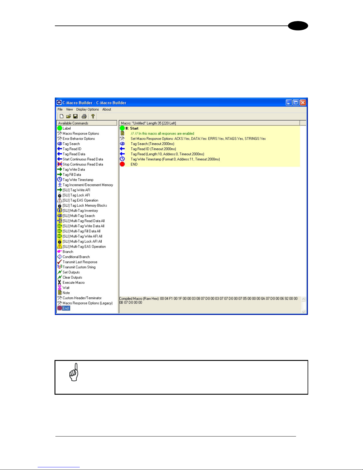
2.7.2 C-Macro Builder™
C-Macro Builder™ is an easy to use GUI-driven utility for Windows that allows users to
create powerful RFID command macro programs.
Figure 18: C-Macro Builder™
When used in conjunction with the Cobalt Dashboard™, users can easily download, erase,
backup and manage multiple RFID command macros and macro triggers for each Subnet
Node. See Chapter 3 for more on macros.
NOTE
For specific information regarding the configuration and use of either of
these utilities, please see the accompanying documentation included when
downloading each software application.
Page 30

GWY-01-PBS-01
22
3
3 RFID COMMAND MACROS
3.1 WHAT ARE RFID COMMAND MACROS?
RFID Command Macros are a powerful feature of Datalogic Automation Cobalt Controllers.
Macros are simple programs that direct a controller to execute multiple pre-programmed
instructions.
Because macros reside within the controller’s internal memory, they can be programmed to
instruct the controller to automatically read and/or write a specified set of data to an RFID tag
without the controller ever having to receive a command from the host. In fact, the controllers
do not even require a connection to a host in order to execute macros.
Each macro can contain up to 255 bytes of data and each supported controller can store up
to eight macros at a time. Though they are stored locally on the controller, macros are also
backed up in the Gateway’s flash memory as well.
3.2 WHY USE MACROS?
The power of macros is in distributed intelligence, the reduction in network bus traffic and the
ability to accelerate routine decision making at the point of data collection.
3.3 WHAT CAN MACROS DO?
In addition to the automated reading and writing of data, macro capabilities include:
The ability to write time stamps to RFID tags
The ability to filter command responses to only those of interest to the host (such as
when an error occurs or when a tag has arrived in the RF field)
The ability to harness powerful logic and triggering capabilities such as; read, write,
start/stop continuous read, data compare, branch, transmit custom string, and set
outputs.
3.4 WHAT IS A MACRO TRIGGER?
Macros are initiated by “triggers.” Triggers can be configured in numerous ways. A simple
command from the host, such as “execute macro number three” can be considered a trigger.
Triggers can be configured, for example, to activate a macro when a tag enters or leaves a
controller’s RF field.
Datalogic Automation RFID controllers can store up to eight separate triggers in addition to
the eight macros they can also house. Any trigger can activate any of the eight stored
macros.
Page 31

RFID COMMAND MACROS
23
3
3.5 HOW ARE MACROS CREATED?
Macros are created using the powerful, yet simple, C-Macro Builder™
utility from Datalogic
Automation. The easy to use GUI allows the user to create powerful RFID macro programs
quickly and easily.
When used with Datalogic Automation Cobalt Dashboard™
utility, users can effortlessly
download, erase, and manage their macros and triggers, as well as set the operational
configurations of their RFID controllers and Subnet16™ Gateways.
3.6 WHICH COMMUNICATION INTERFACES SUPPORT THE USE OF
MACROS?
Macros are supported on the following Cobalt Controllers: Ethernet, Profibus, DeviceNet,
RS232 and USB interfaces.
3.7 WHAT HAPPENS TO EXISTING MACROS IF A CONTROLLER MUST
BE REPLACED?
When using a Subnet16™ Gateway, users do not need to worry. Macros and triggers
normally residing in an RFID controller’s flash memory are always backed up in the
Gateway’s flash memory as well. Therefore, if a controller should ever require replacement,
all existing macro and trigger settings are automatically exported from the Gateway to the
new RFID controller.
In short, when an RFID controller is initially connected to the Gateway, macro and trigger
data from the controller’s flash memory is compared to the macro and trigger data backed up
in the Gateway from the previous RFID controller. If the data does not match that which is
stored on the Gateway, the controller’s flash memory will be overwritten with the backed up
data stored in the Gateway’s flash memory.
3.8 HOW CAN I LEARN MORE ABOUT THE DASHBOARD AND C-
MACRO BUILDER?
More information regarding macros, triggers, uploading, downloading, configuring and
monitoring Datalogic Automation RFID equipment is available in the respective User’s
Manuals for these products, which are available on the Datalogic Automation website at:
www.automation.datalogic.com
Page 32

GWY-01-PBS-01
24
4
4 COMMAND PROTOCOL
A command is initiated by a host PC or Programmable Logic Controller (PLC) and is
distributed to the Gateway over a network connection. Once issued, the command is then
executed directly by the Gateway or is otherwise routed to the appropriate RFID controller
(specified by its numerical “Node ID” value, for which there are 16).
In general, there are two types of commands that can be issued:
Controller Commands - commands intended for one of the attached RFID
controllers. “Read Data” and “Write Data” are two common controller commands.
Gateway Commands - commands intended for the Gateway itself. Gateway
commands are those commands that query the Gateway for information or instruct
the Gateway to perform a task. The commands “Get Node Status List” and “Set
Notification Mask” are examples of Gateway commands.
4.1 CBX COMMAND PROTOCOL OVERVIEW
In order to execute RFID commands properly, the RFID device and host computer must be
able to communicate using the same language. The language that is used to communicate is
referred to as the Command Protocol. The command protocol used by GWY-01-PBS-01 is
called "CBx".
The CBx Command Protocol is an advanced protocol that supports Multidrop Subnet16
networking with TCP/IP, Profibus and Industrial Ethernet applications. It is based on a
double-byte oriented packet structure where commands always contain a minimum of six
data “words” (12 bytes) - even when one or more packet elements are not applicable to the
command.
The CBx packet structures described herein are protocol independent and therefore can be
implemented the same for all protocols (Ethernet/IP, Modbus TCP, Profibus, etc.).
NOTE
For complete command and response packet structures and examples of
each RFID command, refer to the CBx Command Protocol Reference
Manual available at: www.automation.datalogic.com.
Page 33

COMMAND PROTOCOL
25
4
4.2 CBX - COMMAND PACKET STRUCTURE
Below is the packet structure of a standard CBx command.
Word # Command Packet Element MSB LSB
01
Overall Length: 2-byte value indicating
the number of “words” in the command
packet. This value will always be at least 6
words.
0x00 0x06 + (number
of any additional
words)
02
Command ID: 0xAA + 1-byte value
indicating command to perform.
0xAA <Command ID>
03
0x00 in MSB, Node ID in LSB 0x00 <Node ID>
04
Timeout Value: 2-byte integer for the
length of time allowed for the completion of
the command, measured in 1 millisecond
units, where 0x07D0 = 2000 x .001 = 2
seconds.
0x07 0xD0
05
Start Address: 2-byte integer indicating
the location of tag memory where a
Read/Write operation will begin (when
applicable).
<Start MSB> <Start LSB>
06
Block Size: 2-byte integer indicating the
number of bytes that are to be read from or
written to a tag beginning at the specified
Start Address (when applicable).
<Length
MSB>
<Length LSB>
07
Additional Data Byte Values 1 & 2: holds
2 bytes of data used for fills, writes, etc.
(when applicable)
<D1> <D2>
08
Additional Data Byte Values 3 & 4:
(when applicable)
<D3> <D4>
Table 3: CBx Command Packet Structure
Page 34

GWY-01-PBS-01
26
4
4.3 CBX - RESPONSE PACKET STRUCTURE
After performing a command, the Gateway or RFID controller will issue a host-bound
response packet. Below is the packet structure of a standard CBx response message.
Word # Response Packet Element MSB LSB
01
Overall Length: 2-byte integer indicating
the number of “words” in the response
packet. This value will always be at least 6
(+ number of any data words retrieved).
0x00 0x06 + (number
of any retrieved
words)
02
0xAA in MSB
Command Echo in LSB
0xAA <Command
Echo>
03
Instance Counter: 1-byte value indicating
the number of responses generated by the
Node ID identified in the LSB (see details
below).
Node ID Echo: 1-byte value indicating the
Node ID of the controller that performed
the command.
<IC> <Node ID
Echo>
04 Month and Day Timestamp
<Month> <Day>
05 Hour and Minute Timestamp
<Hour> <Minute>
06
Second Timestamp in MSB
Additional Data Length in LSB: 1-byte
value indicates number of additional bytes
retrieved.
<Second> <N-bytes>
07
Retrieved Data Bytes 1 and 2: holds 2
bytes of retrieved data from tag reads,
serial numbers, etc. (when applicable)
<D1> <D2>
Table 4: CBx - Response Packet Structure
4.3.1 Instance Counter
The Instance Counter is a one-byte value used by the Subnet16 Gateway to track the
number of responses generated by the controller at a given Node ID. The Gateway tallies, in
its internal RAM, separate Instance Counter values for each Node ID.
A Node ID’s Instance Counter will be incremented by one following each response. If, for
example, the controller at Node 01 has generated 10 responses, its Instance Counter value
will read 0x0A. However, when the Gateway is rebooted or power-cycled, the Instance
Counter values for all Node IDs will be reset to zero (0x00).
Page 35

COMMAND PROTOCOL
27
4
4.4 CBX COMMANDS TABLE
The table below lists the CBx protocol RFID commands supported by the Gateway and RFID
Controllers.
Command ID Command Name Description
RFID Tag Commands
0x02
Lock Memory Block Write protects a block of tag memory
0x04
Fill Tag
Writes a specified data byte value to all
defined tag addresses
0x05
Read Data
Reads a specified length of data from a
contiguous (sequential) area of tag
memory
0x06
Write Data
Writes a specified number of bytes to a
contiguous area of tag memory
0x07
Read Tag ID Reads a tag’s unique tag ID number
0x08
Tag Search
Instructs the controller to search for a tag
in its RF field
0x0C
Execute Macro
Instructs the controller to execute one of
its eight possible macros
0x0D
Start Continuous Read
Instructs the controller to start or stop
Continuous Read mode.
0x0E
Read Tag ID and Data
Reads a tag’s ID and the requested
number of bytes from tag memory
0x0F
Start Continuous Read Tag ID
and Data
Places the controller into (or out of)
Continuous Read mode and (when
evoked) will retrieve a tag’s ID.
Gateway Information Commands
0x10
Get Gateway Software Version
Retrieves the version number of the
firmware code installed on the Gateway
0x11
Get Gateway Name
Retrieves the Gateway’s user-defined
ASCII name
0x12
Get DIP-switch Settings
Retrieves the status of the Gateway
configuration DIP switches
0x13
Get Node Status List
Retrieves the operational status of the
Gateway Subnet Nodes
0x14
Get Notification Mask
Retrieves the user-defined 16-bit
“Notification Mask” that determines for
which events the Gateway notifies the
host PC
0x15
Get Last Gateway Error
Retrieves information from the Gateway
regarding the last or most recent error
that was experienced
0x16
Get Gateway Time
Retrieves the current date and time as
set internally on the Gateway
Page 36

GWY-01-PBS-01
28
4
Command ID Command Name Description
0x1C
Get Subnet Baud Rate
Retrieves the baud rate of the Subnet
network
0x21
Set Gateway Name
Writes to flash memory, a user-defined
“friendly” name for the Gateway
0x24
Set Notification Mask
Used to customize or modify the
Gateway’s 16-bit Notification Mask
0x26
Set Gateway Time
Used to set the Gateway’s internal clock
and calendar
0x2C
Set Subnet Baud Rate
Used to modify and store changes to the
Subnet network baud rate
RFID Controller Commands
0x30
Get Controller Name
Retrieves the controller’s user-defined
name
0x33
Get Controller Configuration
Retrieves the controller’s configuration
settings
0x38
Get Controller Info
Retrieves hardware, firmware and serial
number information from the controller
0x40
Set Controller Name
Used to set (create or modify) the userdefined name for the controller
0x43
Set Controller Configuration
Used to set (configure or modify) the
controller’s configuration parameters and
settings
0x4E
Set Controller Time Used to set the time for the controller
0x53
Initialize Controller
Removes all configuration settings stored
for the controller
0x54
Reset Controller Resets power to the controller
Gateway Subnet Commands
0x60
Initialize Gateway
Clears all Subnet Node configuration
information stored in the Gateway’s flash
memory
0x61
Reset Gateway
Performs an electrical reset of the
Gateway
0x62
Initialize All Nodes
Removes all stored configuration
information for all nodes and reconfigures
them to factory defaults
0x63
Initialize All Node Macros
Removes all stored macros from all
nodes
0x70
Start Subnet
Instructs the Gateway to begin “polling”
the Subnet network
0x71
Move Controller
Used to move all stored configuration
data for a particular Node ID to another
specified Node ID
Page 37

COMMAND PROTOCOL
29
4
Command ID Command Name Description
0x79
Clear Pending Response
Deletes all pending or buffered
responses in the Gateway and resets all
Instance Counters to zero
Multi-Tag RFID Commands
0x92
Multi-Tag Read ID and Data All
Retrieves the tag ID number and a
contiguous segment of data from all
RFID tags in range
0x95
Multi-Tag Block Read All
Retrieves a contiguous segment of data
from all RFID tags in range
0x96
Multi-Tag Block Write All
Writes a contiguous segment of data to
all RFID tags in range
0x97
Multi-Tag Get Inventory
Retrieves the tag ID number from all
RFID tags found in range
0x98
Multi-Tag Search All
Checks for the presence of RFID tags in
RF range and returns only the number of
tags found
0xA5
Multi-Tag Block Read by ID
Reads a contiguous segment of data
from a specific RFID tag identified by its
tag ID
0xA6
Multi-Tag Block Write by ID
Writes a contiguous segment of data to a
specific RFID tag identified by its tag ID
Table 5: CBx Commands
4.5 CBX COMMAND PROTOCOL EXAMPLES
4.5.1 CBx - Controller Command Example
In the example below, Command 0x05 (Read Data) is issued to the RFID controller at Node
01. The controller is instructed to read four bytes of data from a tag beginning at tag address
0x0020. The Timeout Value, measured in milliseconds, is set for two seconds for the
completion of this command (0x07D0 = 2000 x .001 = 2 seconds).
Word # Packet Element MSB LSB
01
Overall Length of Command (in "words") 0x00 0x06
02
0xAA in MSB
Command ID in LSB: (0x05 - Read Data)
0xAA 0x05
03
0x00 in MSB
Node ID in LSB: (0x01)
0x00 0x01
04
Timeout Value: (2 seconds) 0x07 0xD0
05
Start Address: (0x0020) 0x00 0x20
06
Read Length: (4 bytes) 0x00 0x04
Table 6: Controller Command Example
Page 38

GWY-01-PBS-01
30
4
4.5.2 CBx - Controller Response Example
Below is a controller’s response after successfully completing the Read Data command (as
issued in the previous example).
Word # Packet Element MSB LSB
01
Overall Length of Response (in "words") 0x00 0x08
02
0xAA in MSB
Command Echo in LSB: (0x05 - Read
Data)
0xAA 0x05
03
Instance Counter in MSB
Node ID Echo in LSB
<IC> 0x01
04
Month and Day Timestamp (March 19
th
) 0x03 0x13
05
Hour and Minute Timestamp (10:11: AM) 0x0A 0x0B
06
Seconds Timestamp in MSB: (36
seconds)
Additional Data Length in LSB (4 bytes)
0x24 0x04
07
Retrieved Data (bytes 1 and 2) 0x01 0x02
08
Retrieved Data (bytes 3 and 4) 0x03 0x04
Table 7: Controller Response Example
4.5.3 CBx - Gateway Command Example
In this example, the host issues Command 0x13 (Get Node Status List), which retrieves from
the Gateway, a list that indicates the operating status of the 16 Nodes.
Word # Packet Element MSB LSB
01
Overall Length of Command (in “words”) 0x00 0x06
02
0xAA in MSB
Command ID in LSB: (0x13 - Get Node
Status List)
0xAA 0x13
03
0x00 in MSB
Node ID in LSB: (0x20 = Gateway Node
32)
0x00 0x20
04
Not Used: 0x00, 0x00 (default) 0x00 0x00
05
Not Used: 0x00, 0x00 (default) 0x00 0x00
06
Not Used: 0x00, 0x00 (default) 0x00 0x00
Table 8: Gateway Command Example
Note that even though the last three words (6 bytes) of this command are not used, these
parameters still require zero’s (0x00, 0x00) and are to be included when calculating Overall
Length.
Page 39

COMMAND PROTOCOL
31
4
4.5.4 CBx - Gateway Response Example
Below is the Gateway response to the command “Get Node Status List” (as issued in the
previous example).
Word # Packet Element MSB LSB
01
Overall Length of Response (in “words,”
not including the previous 2-bytes – CBx
Header and Node ID Echo)
0x00 0x0E
02
0xAA in MSB
Command Echo in LSB: (0x13)
0xAA 0x13
03
Instance Counter in MSB
Node ID Echo in LSB (0x20 = Gateway
Node 32)
<IC> 0x20
04
Month and Day Timestamp (March 19th) 0x03 0x13
05
Hour and Minute Timestamp (10:11: AM) 0x0A 0x0B
06
Seconds Timestamp in MSB: (36
seconds)
Additional Data Length in LSB: (16 bytes)
0x24 0x10
07 Status of Node ID 1 and 2
0x00 0x00
08 Status of Node ID 3 and 4
0x04 0x00
09 Status of Node ID 5 and 6
0x00 0x04
0A Status of Node ID 7 and 8
0x00 0x00
0B Status of Node ID 9 and 10
0x00 0x00
0C Status of Node ID 11 and 12
0x00 0x00
0D Status of Node ID 13 and 14
0x00 0x00
0E Status of Node ID 15 and 16
0x00 0x00
Table 9: Gateway Response Example
In the above example, the Node Status Byte “0x04” (meaning “Controller Healthy”) was
reported for Nodes 03 and 06, indicating that the Gateway recognizes functioning RFID
controllers at Node 03 and Node 06. (See the Node Status Byte Definition Table below for
more information).
Page 40

GWY-01-PBS-01
32
4
4.6 NODE STATUS BYTE DEFINITION TABLE
Node Status
Byte
Node Status Status Description
0
CONTROLLER
INACTIVE
The controller at this node has not responded to a
poll for at least 40 seconds.
If a controller does eventually respond at this Node
ID, its status will be changed to “0x04 CONTROLLER HEALTHY”.
1
CONTROLLER
STOPPED
RESPONDING
The controller at this node has not responded to a
poll in over 10 seconds.
If the controller does not respond to a poll within
another 30 seconds, its status will be changed to
“0x00 - CONTROLLER INACTIVE”.
If the controller does eventually respond to a poll,
its status will be changed back to “0x04 CONTROLLER HEALTHY”.
2
CONTROLLER HAS
PROBLEM
The controller at this node has missed at least 3
consecutive polls.
If the controller does not respond to a poll within
another 10 seconds, its status will be changed to
“0x01 - CONTROLLER STOPPED RESPONDING.”
If the controller does eventually respond to a poll,
its status will be changed back to “0x04 CONTROLLER HEALTHY”.
3
CONTROLLER
EXPECTED SOON
This Node Status indicates that a controller is
temporarily disconnected or that it is being moved
to another Node ID.
Because a controller is “expected” to appear soon,
the Gateway will poll this node more frequently than
other ‘inactive’ nodes.
4
CONTROLLER
HEALTHY
The controller at this node is healthy and
responding to polls.
However, if the controller misses 3 consecutive
polls, its status will be changed to “0x02 CONTROLLER HAS PROBLEM”.
5
CONTROLLER
DOWNLOADING
This status is only applied to a controller that is
currently downloading and installing new firmware
to its flash memory.
To optimize polling and allow for the fastest
possible firmware installation, the Gateway will
temporarily halt the polling of this node until the
controller has finished its installation.
Table 10: Node Status Byte Definition
Page 41

COMMAND PROTOCOL
33
4
4.7 CBX ERROR RESPONSE PACKET STRUCTURE
Below is the packet structure of a CBx error response. Note that the one-byte Error Code
value is returned in the MSB of the seventh data word.
Error Response Element MSB LSB
Overall Length: 2-byte value indicating the number
of “words” in the Response Packet. This value will
always be at least 7 words (6 + 1 for the error
code).
0x00 0x07
Error Flag: 0xFF in the MSB indicates that an error
occurred.
Error Information Byte: 0xFF in the LSB indicates
that a controller-based error occurred. Any value
other than 0xFF indicates that a Gateway-based
error occurred (and indicates the command that
was attempted when the error occurred).
0xFF 0xFF
Instance Counter: This 1-byte value tallies the
number of responses from a given Node ID.
Node ID Echo: The 1-byte LSB value indicates the
Node ID of the controller for which the command
was intended.
<IC> 0x01
Month and Day Timestamp <Month> <Day>
Hour and Minute Timestamp <Hour> <Minute>
Seconds Timestamp in MSB
Number of Additional Bytes Retrieved in LSB (0x01
for error responses)
<Seconds> 0x01
Error Code: 1-byte Error Code in MSB
0x00 in LSB
<Error Code> 0x00
Table 11: CBx Error Response Packet Structure
Page 42

GWY-01-PBS-01
34
4
4.8 CBX ERROR CODE TABLE
Error Code Error Description
0x04
FILL TAG FAILED Fill Tag Command Failed
0x05
READ DATA FAILED Read Data Command Failed
0x06
WRITE DATA FAILED Write Data Command Failed
0x07
READ TAG ID FAILED /
TAG SEARCH FAILED
Read Tag ID Command Failed,
Tag Search Command Failed
and/or No Tag Found
0x21
INVALID SYNTAX Command Contained a Syntax
Error
0x23
INVALID TAG TYPE Invalid Tag Type Specified
0x30
INTERNAL
CONTROLLER ERROR
Generic Internal Controller Error
0x31
INVALID CONTROLLER
TYPE
Invalid Controller Type (when
Setting Configuration)
0x34
INVALID VERSION Invalid Software Version
Specified (when Setting
Configuration)
0x35
INVALID RESET Invalid Hardware Reset
0x36
WRITE
CONFIGURATION
FAILED
Set Configuration Command
Failed
0x37
READ CONFIGURATION
FAILED
Get Configuration Command
Failed
0x80
UNKNOWN GATEWAY
ERROR
Generic Gateway Error – an
undetermined error occurred.
0x81
COMMAND
MALFORMED
Generic Command Syntax Error
0x82
COMMAND PROTOCOL
MISMATCH
An invalid protocol value was
specified in the command
0x83
COMMAND INVALID
OPCODE
An invalid Opcode (Command ID
number) was specified in the
command
0x84
COMMAND INVALID
PARAMETER
A parameter specified in the
command was invalid
0x85
COMMAND INVALID
CONTROLLER ID
A Controller ID (Node ID)
specified in the command was
invalid, or no controller
detected/present at the specified
node
0x86
COMMAND INACTIVE
CONTROLLER ID
A Controller ID (Node ID)
specified in the command is
currently inactive.
0x87
SUBNET DEVICE
SELECT FAILED
Internal Subnet Error – the
specified Subnet device failed.
0x88
SUBNET DEVICE
FAILED TO
ACKNOWLEDGE
Internal Subnet Error - the
specified Subnet device failed to
respond to the Gateway’s polling.
0x89
SUBNET RESPONSE
MALFORMED
Internal Subnet Error – a
controller returned a malformed
response.
Page 43

COMMAND PROTOCOL
35
4
Error Code Error Description
0x8A
SUBNET RESPONSE
TIMEOUT
Internal Subnet Error – a
controller was unable to generate
a response before timeout was
reached.
0x8B
SUBNET RESPONSE
INVALID CHECKSUM
Internal Subnet Error – a
controller generated a response
that has an invalid checksum.
0x8C
SUBNET DEVICE
CONFLICT DETECTED
Internal Subnet Error – a Node
ID conflict has been detected
0x8D
BUFFER OVERFLOW Internal Gateway Error –
Gateway buffer limit was
exceeded
0x8E
FLASH FAILURE Internal Gateway Error –
Gateway flash memory failure
0x92
SUBNET16 ONLY
COMMAND
A Subnet16-only command was
issued when in MUX32 mode.
0x93
NODE MISMATCH
ERROR
The Node ID specified in the
command did not match the
Node to which the command was
sent.
0x94
CRC ERROR Cyclic Redundancy Check Error
0x95
PROTOCOL ERROR Internal Communications Error
Table 12: CBx Error Codes
4.9 CBX - ERROR RESPONSE EXAMPLE
Below is an example of a typical controller generated error response following a failed Read
Data Command. For this example, a “Tag not Found” error was generated.
Error Response Parameter MSB LSB
0x00 in MSB
Overall Length of Response in LSB (in words)
0x00
0x07
Error Flag in MSB
Error Information Byte in LSB
0xFF
0xFF
0x00 in MSB
Node ID Echo in LSB
0x00
0x01
Month and Day Timestamp: (March 19th) 0x03
0x13
Hour and Minute Timestamp: (9:30: AM) 0x09
0x1E
Seconds Timestamp in MSB (:03 seconds)
Number of Additional Bytes Retrieved in LSB
(0x01 for error responses)
0x03
0x01
Error Code in MSB: (0x07 = "Tag not Found")
0x00 in LSB
0x07 0x00
Table 13: CBx Error Response Example
Page 44

GWY-01-PBS-01
36
4
4.10 NOTIFICATION MESSAGES
Notification Messages are small host-bound informational packets of data that are issued
by the Gateway when a specified Notification Event (or series of events) occurs within the
Gateway or on the Subnet network. For example, the Gateway can be configured to send the
host a Notification Message when a controller is attached, or removed, or experiences a
problem.
The Gateway stores nine different Notification Messages internally (all of which are enabled
by default). A 16-bit value, called the Notification Mask, controls which Notification Events
trigger Notification Messages to the host. Bits 00 through 08 in the 16-bit Notification Mask
correspond to the nine possible Notification Messages. The remaining 7 bits (bits 09-15) are
not implemented at this time (default value is zero for each bit).
Notification Messages are enabled by changing the associated bit from zero to one within the
Notification Mask. A bit is either set to “0” (OFF – disabled) or “1” (ON – enabled). When a bit
is turned ON, the related Notification Message will be enabled. The next time the enabled
Notification Event occurs, the corresponding Notification Message will be generated and
immediately delivered to the host.
When a Notification Event occurs it generates a Notification Message which is written to the
Host. Notification Messages include a one-byte value indicating which of the nine possible
Notification Events occurred. Notification Messages also contain a one-byte value that
identifies the affected Node ID.
For Notification Messages, a handshaking scheme of enabling and clearing a specific bit in
the Notification Mask is implemented (as previously explained).
To enable all nine Notification Messages, the 2-byte Notification Mask would read:
0x01FF.
16-BIT NOTIFICATION MASK
Bits
15 14 13 12 11 10 9 8 7 6 5 4 3 2 1 0
Value
[0] [0] [0] [0] [0] [0] [0]
[1] [1] [1] [1] [1] [1] [1] [1] [1]
Page 45

COMMAND PROTOCOL
37
4
4.10.1 Notification Message Table
The following table contains a listing of the nine possible Notification Messages.
Bit Notification Message Event Description
0
CONTROLLER IS HEALTHY Sent whenever the status of a controller changes
to ‘Healthy’
1
CONTROLLER HAS
PROBLEM
Sent whenever a controller is marked ‘Has
Problem’
2
CONTROLLER STOPPED
RESPONDING
Sent whenever a controller is marked ‘Stopped
Responding’
3
CONTROLLER DEACTIVATED Sent whenever a controller is deactivated (is
marked ‘Inactive’)
4
CONTROLLER MISSED POLL Sent whenever a controller misses a poll
5
CONTROLLER ADDRESS
CONFLICT
Sent whenever the Gateway detects a Node ID
conflict
6
CONTROLLER
CONFIGURATION FAILURE
Sent whenever the Gateway fails to configure a
controller
7
TAG PRESENT AT NODE* Sent whenever a tag is first recognized in the RF
field of the specified node
8
TAG NOT PRESENT AT
NODE*
Sent when no tag is recognized or when a
previously recognized tag is no longer
acknowledged in the specified node’s RF field
Table 14: Notification Messages
* Tag Presence must be enabled on the RFID controller.
4.10.2 Notification Mask Example
In the following example, an RFID controller is attached to the Gateway’s Subnet network.
After power is applied to the controller, the Gateway immediately attempts to determine its
Node ID (Node 04 in this example). After recognizing a stored Node ID configuration, the
Gateway allows the device onto the Subnet network.
Now if bit 00 in the Notification Mask was enabled (set to one = ON), Notification Event 00
would be triggered and the Gateway would immediately write Notification Message 00 to the
Host. The Notification Message would indicate that a new controller was recognized at Node
04 and is functioning properly (i.e. the controller is healthy).
If, on the other hand, the recently connected controller does not power-up, or fails to initialize
properly, and bit 01 in the Notification Mask is enabled, Notification Event 01 will be
triggered, in which case the Gateway will write Notification Message 01 to the Host. This
message informs the host that the controller at Node 04 is experiencing a problem.
Page 46

GWY-01-PBS-01
38
4
4.10.3 Notification Message Packet Structure
Description MSB LSB
Overall Length of Notification Message (in words) 0x00 0x06
0xFE in MSB = Notification Message Flag
Notification Event in LSB
0xFE <Notification
Event>
Instance Counter in MSB (a Notification Message is
considered a response; therefore the Instance
Counter will be incremented by one)
Node ID in LSB (04 for the above example)
<IC> 0x04
Month and Day Timestamp
<Month> <Day>
Hour and Minute Timestamp
<Hour> <Minute>
Seconds Timestamp in MSB
0x00 in LSB
<Second> 0x00
Table 15: Notification Message - Packet Structure
Page 47

PROFIBUS INTERFACE
39
5
5 PROFIBUS INTERFACE
5.1 PROFIBUS OVERVIEW
Profibus was created under German Government leadership in co-operation with automation
manufacturers (Siemens) in 1989. Today it is commonly found in Process Control, large
assembly and material handling machines. Just a single-cable which is able to wire multiinput sensor blocks, pneumatic valves, complex intelligent devices, smaller sub-networks,
operator interfaces and many other devices.
5.2 PROFIBUS-DP
Basically Profibus is available in three different versions:
Profibus-DP (Decentralized Periphery)
Multiple masters are possible with Profibus-DP, in which case each slave device is
assigned to one master. This means that multiple masters can read inputs from the
device but only one master can write outputs to that device.
Profibus-FMS
It is a peer to peer messaging format, which allows masters to communicate with one
another. Just as in Profibus-DP, up to 126 nodes are available and all can be masters
if desired. FMS messages consume more overhead than DP messages.
Profibus-PA
PA protocol is the same as the latest Profibus-DP except that voltage and current
levels are reduced to meet the requirements of intrinsic safety (Class I div. II) for the
process industry.
The Gateway Profibus supports Profibus-DP only, since this version has been specifically
designed for factory automation.
MAIN FEATURES:
Maximum Number of Nodes: 126
Distance: 100 m to 24 Km (with repeaters and fibre optic transmission)
Baud rate: 9600 to 12M bps
Page 48

GWY-01-PBS-01
40
5
5.3 DATA EXCHANGE
The Master Profibus is usually a PLC (Siemens S7 or others) but it could be a PC based
device as well. The Gateway Profibus is always Slave in the Profibus network.
PLC
RFID
Controller
RFID
Controller
RFID
Controller
RFID
Controller
RFID
Controller
GWY-01-PBS-01
Subnet16™ Network
Profibus Network
Profibus Master
Profibus Slave
Figure 19: Profibus-DP Network Diagram
Basically two shared memory areas (Exchange Areas) are used to exchange information
between the SLAVE and the MASTER, both devices provide information to each other.
INPUT
AREA
OUTPUT
AREA
PLC GWY-01-PBS-01
Write Read
Write Read
Exchange Areas
Mast er Slave
Figure 20: Profibus Communication – Data Exchange Areas Diagram
Input and output areas always refer to the Master: this means that the Gateway writes to the
Input buffer and the PLC writes to the Output buffer.
The dimension of the exchange areas can be set to different values by the PLC through the
GSD file: the Gateway Profibus allows up to 152 bytes as a combined total of the Input
and Output Areas.
NOTE
For further information regarding Fieldbus interfacing including
downloadable support files, go to the HMS website at
http://www.anybus.com, choose the link to the support page, select the
Anybus-CompactCom product type and then your network type.
Page 49

PROFIBUS INTERFACE
41
5
5.4 PROTOCOL IMPLEMENTATION
5.4.1 Definitions
In the protocol description we'll use the following definitions:
Input field: is the set of master inputs that can be modified by the specific slave
Output field: is the set of master outputs that can be read by the specific slave
MaxInBytes: is the number of input bytes shared by the master and the specific slave
MaxOutBytes: is the number of output bytes shared by the master and the specific
slave
IN[ Nin ] represent the input byte number Nin, where numbering starts from 0 to
MaxInBytes-1
OUT[ Nout ] represent the output byte number Nout, where numbering starts from 0
to MaxOutBytes-1
Obviously, MaxInBytes and MaxOutBytes are respectively the configured INPUT and
OUTPUT AREA sizes.
The I/O Exchange Areas are actually updated and read every 30 ms at the Gateway Profibus
side. So after an RFID tag is read the worst delivery time from the Gateway Profibus to the
Master station is about 30 ms plus the intrinsic PROFIBUS DP delay and the Master delay.
This product implements the Datalogic AnyBus Driver (DAD) which is a layer that is built
upon the intrinsic fieldbus data exchange mechanism. The Driver is needed to add features
such as flow control and fragmentation.
In order to implement the flow controlled version of the driver, I/O Exchange Areas must be
congruently compiled in both directions. INPUT Area is the Exchange buffer from Gateway
Profibus to the Master while OUTPUT Area is the exchange buffer from the Master to the
Gateway Profibus. Only the first three bytes are used by the Datalogic AnyBus Driver layer in
both buffers for the extended protocol.
These are:
byte 0: Control Field, used to issue and control the Datalogic AnyBus Driver
primitives such as flowcontrol, fragmentation and resynchronization;
byte 1: Service Access Point Field, used to distinguish among different services but
also to provide future expandibility. Since this SAP definition is introduced by the
Datalogic AnyBus Driver, it must not be confused with the AnyBus SAP that is defined
by the international standard.
byte 2: Length Field, that contains the number of bytes used by the application layer.
This number must always be less than or equal to MaxInBytes-3 for the IN[] buffer
and less than or equal to MaxOutBytes-3 for the OUT[] buffer.
Page 50

GWY-01-PBS-01
42
5
Figure 21: Exchange Area Buffer Structure
5.4.2 Control Field
The Input field structure reserves IN[0] for handshake purposes: bit 0 and bit 1 are used for
this. Bit 6 is set to 1 in order to specify the messaging protocol number 1 is in use. The
Output field structure is symmetrical, and reserves bit 0 and 1 for handshake purposes. Bit 6
is set to 1 in order to specify the messaging protocol number 1 is in use. Bit 2 of the Output
buffer is used to request a clear of the synchronization numbers (bit 0 and bit 1 of both Input
and Output buffers).
This is called a resynchronization request and it is always initiated by the Master Station. The
Slave must acknowledge the request, using bit 2 of the Input buffer. Bit 3 is used to control a
fragmentation sequence in both directions.
More precisely,
function of the IN[0] byte:
IN[0].bit0 = TxBufferFull, toggles when new data is available on IN[1] .. IN[Nin] input
area
IN[0].bit1 = RxBufferEmpty, toggles when rx block has been read on OUT[1] .. OUT[
Nout]
IN[0].bit2 = Resync Acknowledge, set to 1 as an acknowledge to a resync request.
IN[0].bit3 = More Bit, it must be set to 1 when this is not the last piece of a
fragmentation sequence. It must be set to 0 when this is the last piece of a
fragmentation sequence.
IN[0].bit4,5,7 = set to 0,0,0 when this messaging protocol is used.
IN[0].bit6 = set to 1 when this messaging protocol is used.
Page 51

PROFIBUS INTERFACE
43
5
function of the OUT[0] byte:
OUT[0].bit0 = TxBufferEmpty, toggles when transmitted data block has been read
from master.
OUT[0].bit1 = RxBufferFull, toggles when new data block is available from master.
OUT[0].bit2 = Resync Request, set to 1 for 1 second to resynchronize a slave. After
resynchronization, all 4 handshake bits are set to 0 and next toggle brings them to 1.
OUT[0].bit3 = More Bit, it must be set to 1 when this is not the last piece of a
fragmentation sequence. It must be set to 0 when this is the last piece of a
fragmentation sequence.
OUT[0].bit4,5,7 = set to 0,0,0 when this messaging protocol is used.
OUT[0].bit6 = set to 1 when this messaging protocol is used.
The following figure shows how it is possible to exchange messages with flow control using
bit 0 and bit 1 in the IN/OUT buffers.
Figure 22: Message Exchange with Flow Control
Page 52

GWY-01-PBS-01
44
5
Data Transmission Slave → Master
The transmission state machine is shown to understand how a single block is transmitted
and received. This protocol guarantees a basic flow control mechanism from slave to master.
Figure 23: Slave to Master Transmission State Machine
Data Transmission Master → Slave
The receive state machine is shown to understand how a single block is transmitted by the
master and received by a slave. This protocol guarantees a basic flow control mechanism
from master to slave.
Figure 24: Master to Slave Reception State Machine
Page 53

PROFIBUS INTERFACE
45
5
Resynchronization Protocol
Resynchronization may be used at the master startup, both to detect if a slave is on line or
not, or to restart the messaging protocol from a predefined state. It is also used during
normal operations in case of errors requiring a protocol reset procedure to be started.
Figure 25: Resynchronization State Machine
5.4.3 SAP Field
SAP (Service Access Point) is an identifier that is used to share the same communication
channel between processes of two remote stations. This allows splitting the single service
into different services.
SAP = 0 is actually used by the slave to transfer acquisition information; it should also
be used to transfer application data from Master to Slave.
SAP = 2 is currently reserved.
SAP = 255 is currently reserved.
Only SAP 255 and 2 are reserved. All other SAPs are free and may be used by new
application programs.
5.4.4 Length Field
The Application layer uses all or a part of the remaining bytes of the Exchange Area buffers
that are not used by the Datalogic AnyBus Driver. The Length Field is introduced to keep the
information of how many bytes are really used by the Application Layer. A fragment that is
not the last one of a fragmentation sequence must fill this field with Max(In/Out)Bytes-3,
depending on whether it is an INPUT/OUTPUT fragment. Otherwise this field is filled with a
number that is less than or equal to Max(In/Out)Bytes-3.
Page 54

GWY-01-PBS-01
46
5
5.4.5 Application Data Buffer
The Application data buffer holds the CBx commands with the syntax explained in chapter 4.
5.5 EXAMPLES OF PROFIBUS COMMAND/RESPONSE MECHANISM
As seen in par. 5.3, there are two buffers – an OUTPUT Buffer that is controlled by the
MASTER, and an INPUT Buffer that is controlled by the slave (the Gateway).
The OUTPUT Buffer is mapped the following way:
Output Buffer
Byte #
00: OUTPUT BUFFER CONTROL BYTE (OBCB)
01: (Always 0)
02: Packet Length in Bytes
03:
04:
05:
06:
07:
08:
09:
10:
-
N-2:
Packet Bytes (Command)
“ “
“ “
“ “
“ “
“ “
“ “
“ “
“ “
“ “
“ “
N-1: Data Consistency Byte (OBDCB)
Byte 0 is the Output Buffer Control Byte. The Master uses the lowest two bits of this byte
for handshaking: to signal that a command is ready for the slave (Bit 1), and to acknowledge
receiving a response from the slave (Bit 0).
OUTPUT BUFFER CONTROL BYTE
7 6 5 4 3 2 1 0
[1]
[0] [0] [0] [0]
[0] [0] [0]
Bit 0 is toggled by the Master to acknowledge a packet (response) from the RFID
Controller.
Bit 1 is toggled by the Master when it has a packet (command) ready for the RFID
Controller.
Bit 2 is set when the Master wishes to initiate a “Resynchronization” with the Slave,
and then cleared when it sees the corresponding handshake from the Slave,
(indicating that the resynchronization is complete).
Page 55

PROFIBUS INTERFACE
47
5
Bit 3 is set by the Slave when the total CBx response being returned to the Master is
larger than the space available in the Input Buffer (or that the packet being returned is
a fragment, and that there are more fragments to follow). This bit is cleared for the
final fragment of a fragmented response – and so the Master can know when all the
fragments of a response have been returned from the Slave.
Bit 7 is always 1, to conform to Datalogic’s proprietary “DAD” Protocol.
Byte 1: is always 0.
Byte 2: contains the length of the packet in bytes (CBx Command or Command Fragment) to
be sent to the RFID Controller. This can be the length of an entire CBx command, or the
length of a fragment of a command, if the CBx command is larger than the space allowed to
send it in a single fragment.
Byte 3 through Byte N-2 are used for the actual CBx Command or Command Fragment to
be sent.
Byte N-1: the final byte of the Output Buffer is the Data Consistency Byte. It is a copy of
the Ouptut Buffer Control Byte. When changes to the Control Byte are made, the same
changes must also be made in the Data Consistency Byte, before the changes “take effect”.
This is to guarantee the validity of the data between the two bytes.
The INPUT Buffer is controlled by the Slave (Cobalt RFID Controller) and is mapped the
same way, except for the packet bytes containing a response (or response fragment) from
the controller.
Input Buffer
Byte #
00: INPUT BUFFER CONTROL BYTE (IBCB)
01: (Always 0)
02: Packet Length in Bytes
03:
04:
05:
06:
07:
08:
09:
10:
-
N-2:
Packet Bytes (Response)
“ “
“ “
“ “
“ “
“ “
“ “
“ “
“ “
“ “
“ “
N-1: Data Consistency Byte (IBDCB)
Page 56

GWY-01-PBS-01
48
5
Byte 0 is the Input Buffer Control Byte. The Slave uses the lowest four bits of this byte for
handshaking: to acknowledge receiving a command from the master (Bit 1), and to signal
that a response is ready for the master (Bit 0).
INPUT BUFFER CONTROL BYTE
7 6 5 4 3 2 1 0
[1]
[0] [0] [0]
[0] [0] [0] [0]
Bit 0 is toggled by the Slave when it has a new packet (response or response
fragment) ready for the Master.
Bit 1 is toggled by the Slave to acknowledge a packet (command or command
fragment) from the Master.
Bit 2 is set by the Slave after it completes resynchronization, and then cleared once
the Master has acknowledged that resynchronization is complete.
Bit 3 is set by the Slave when the total CBx response being returned to the Master is
larger than the space available in the Input Buffer (or that the packet being returned is
a fragment, and that there are more fragments to follow). This bit is cleared for the
final fragment of a fragmented response – and so the Master can know when all the
fragments of a response have been returned from the Slave.
Bit 7 is set to 1 as soon as the Slave has been successfully initialized at power-up,
and remains at 1, to conform to Datalogic’s proprietary “DAD” Protocol.
Byte 1: is always 0.
Byte 2: contains the length of the packet in bytes (CBx response or response fragment) to be
sent back to the Master.
Byte 3 through Byte N-2 are used for the actual CBx response or response fragment to be
sent.
Byte N-1: The final byte of the Input Buffer is the Data Consistency Byte for the Input Buffer.
It is a copy of the Input Buffer Control Byte. The Master should check that these two bytes
are the same, before considering the Input Buffer’s data to be valid.
NOTE
The input and output buffers can exceed 64 bytes. The combined total of the
input and output buffers cannot exceed 152 bytes.
5.5.1 Example 1: Normal Command/Response Sequence
For this example, the Master will send a CBx “Read Tag ID” command to the Slave (the
RFID Controller) to read an 8-byte tag ID from an RFID Tag. First we will see a “Tag Not
Found” error (assuming that the tag is not read) and then we will see a successful read of the
Tag ID.
Page 57

PROFIBUS INTERFACE
49
5
We will assume for this example that both the Input and Output Buffers have been configured
to 32 bytes each. This means that the controllers response (for this command) can fit entirely
in the input buffer, and no fragmentation is required.
Sending the command:
In Byte 2 of the output buffer the Master places the length (in bytes) of the data packet (CBx
Command) we are sending. In this case the CBx command we are sending is 12 bytes. This
length is the length of the command bytes we are interested in sending, not the full size of
the buffer. The length also does not include the “Data Consistency Byte” at the end of the
buffer. That is just a mirror of the Control Byte.
In Byte 3 through Byte 14 the Master places the 12 bytes of this particular CBx command.
Some CBx commands are larger, but all will be at least 12 bytes, even if some of those 12
bytes are not actually used.
(See the Green changes below)
Output Buffer Input Buffer
Byte # Value Byte # Value
00:
80
Output Buffer Control Byte
(OBCB)
7 6 5 4 3 2 1 0
[1] [0] [0] [0] [0] [0] [0] [0]
00
80
Input Buffer Control Byte
(IBCB)
7 6 5 4 3 2 1 0
[1] [0] [0] [0] [0] [0] [0] [0]
01: 00 (Always 0) 01: 00
02:
0C (Packet length in bytes)
02: 00
03:
04:
05:
06:
07:
08:
09:
10:
11:
12:
13:
14:
15:
16:
17:
18:
19:
20:
..
30:
00
06
AA
07
00
01
03
E8
00
00
00
00
00
00
00
00
00
00
..
00
(CBx Command word length MSB)
(CBx Command word length LSB)
Minimum of 6 words
(CBx Command Type) Always AA
(CBx Command Opcode)
0x07 = Read Tag ID
(CBx Command, byte not used)
(CBx Command “Node ID”)
(CBx Command Timeout MSB)
(CBx Command Timeout LSB)
0xE8 = 1000 ms timeout
(CBx Command Not Used)
(CBx Command Not Used)
(CBx Command Not Used)
(CBx Command Not Used)
03:
04:
05:
06:
07:
08:
09:
10:
11:
12:
13:
14:
15:
16:
17:
18:
19:
20:
..
30:
00
00
00
00
00
00
00
00
00
00
00
00
00
00
00
00
00
00
..
00
31: 80
Data Consistency Byte (OBDCB)
31: 80
Data Consistency Byte (IBDCB)
Now that the command is in the Output Buffer, The Master alerts the Slave that the
command is ready. It does this by toggling Bit 1 of the Output Buffer Control Byte (the
OBCB) and then also toggling the same bit in the Output Buffer Data Consistence Byte
(the OBDCB).
NOTE
This bit is a toggle. So if it is 0, it is toggled to 1 to indicate a new command.
If it is 1, it is toggled to 0 to indicate a new command. If the bit is 1, setting it
to 0, and then back to 1 will cause the command to be issued twice.
Page 58

GWY-01-PBS-01
50
5
(See the Green changes below)
Output Buffer Input Buffer
Byte # Value Byte # Value
00:
82
Output Buffer Control Byte
(OBCB)
7 6 5 4 3 2 1 0
[1] [0] [0] [0] [0] [0] [1] [0]
00
80
Input Buffer Control Byte
(IBCB)
7 6 5 4 3 2 1 0
[1] [0] [0] [0] [0] [0] [0] [0]
01: 00 (Always 0) 01: 00
02: 0C (Packet length in bytes) 02: 00
03:
04:
05:
06:
07:
08:
09:
10:
11:
12:
13:
14:
15:
16:
17:
18:
19:
20:
..
30:
00
06
AA
07
00
01
03
E8
00
00
00
00
00
00
00
00
00
00
..
00
(CBx Command word length MSB)
(CBx Command word length LSB)
(CBx Command Type)
(CBx Command Opcode)
(CBx Command, byte not used)
(CBx Command “Node ID”)
(CBx Command Timeout MSB)
(CBx Command Timeout LSB)
(CBx Command Not Used)
(CBx Command Not Used)
(CBx Command Not Used)
(CBx Command Not Used)
03:
04:
05:
06:
07:
08:
09:
10:
11:
12:
13:
14:
15:
16:
17:
18:
19:
20:
..
30:
00
00
00
00
00
00
00
00
00
00
00
00
00
00
00
00
00
00
..
00
31:
82 Data Consistency Byte (OBDCB)
31: 80
Data Consistency Byte (IBDCB)
When the Slave sees Bit 1 of the OBCB & OBDBC toggle, it grabs the command from the
Output Buffer. The Slave then acknowledges the command by toggling Bit 1 of the Input
Buffer Control Byte (the IBCB) and also the same bit of the Input Buffer Data
Consistency Byte (the IBDCB).
Page 59

PROFIBUS INTERFACE
51
5
(See the Green changes below)
Output Buffer Input Buffer
Byte # Value Byte # Value
00:
82
Output Buffer Control Byte
(OBCB)
7 6 5 4 3 2 1 0
[1] [0] [0] [0] [0] [0] [1] [0]
00
82
Input Buffer Control Byte
(IBCB)
7 6 5 4 3 2 1 0
[1] [0] [0] [0] [0] [0] [1] [0]
01: 00 (Always 0) 01: 00
02: 0C (Packet length in bytes) 02: 00
03:
04:
05:
06:
07:
08:
09:
10:
11:
12:
13:
14:
15:
16:
17:
18:
19:
20:
..
30:
00
06
AA
07
00
01
03
E8
00
00
00
00
00
00
00
00
00
00
..
00
(CBx Command word length MSB)
(CBx Command word length LSB)
(CBx Command Type)
(CBx Command Opcode)
(CBx Command, byte not used)
(CBx Command “Node ID”)
(CBx Command Timeout MSB)
(CBx Command Timeout LSB)
(CBx Command Not Used)
(CBx Command Not Used)
(CBx Command Not Used)
(CBx Command Not Used)
03:
04:
05:
06:
07:
08:
09:
10:
11:
12:
13:
14:
15:
16:
17:
18:
19:
20:
..
30:
00
00
00
00
00
00
00
00
00
00
00
00
00
00
00
00
00
00
..
00
31: 82
Data Consistency Byte (OBDCB)
31:
82 Data Consistency Byte (IBDCB)
The Slave writes the response into the Input Buffer, and toggles Bit 0 of the IBCB to
indicate that there is a response fragment ready for the master. Since the entire response fits
in the buffer, it does not need to use fragmentation. The Slave also simultaneously makes
the same changes to the IBDCB.
Page 60

GWY-01-PBS-01
52
5
(See the Green changes below)
Output Buffer Input Buffer
Byte # Value Byte # Value
00:
82
Output Buffer Control Byte
(OBCB)
7 6 5 4 3 2 1 0
[1] [0] [0] [0] [0] [0] [1] [0]
00
83
Input Buffer Control Byte
(IBCB)
7 6 5 4 3 2 1 0
[1] [0] [0] [0] [0] [0] [1] [1]
01: 00 (Always 0) 01: 00 (Always 0)
02: 0C (Packet length in bytes) 02:
0E (Packet length in bytes)
03:
04:
05:
06:
07:
08:
09:
10:
11:
12:
13:
14:
15:
16:
17:
18:
19:
20:
..
30:
00
06
AA
07
00
01
03
E8
00
00
00
00
00
00
00
00
00
00
..
00
(CBx Command word length MSB)
(CBx Command word length LSB)
(CBx Command Type)
(CBx Command Opcode)
(CBx Command, byte not used)
(CBx Command “Node ID”)
(CBx Command Timeout MSB)
(CBx Command Timeout LSB)
(CBx Command Not Used)
(CBx Command Not Used)
(CBx Command Not Used)
(CBx Command Not Used)
03:
04:
05:
06:
07:
08:
09:
10:
11:
12:
13:
14:
15:
16:
17:
18:
19:
20:
..
30:
00
07
FF
FF
00
01
01
01
00
13
22
01
07
00
00
00
00
00
..
00
(CBx Response word length MSB)
(CBx Response word length LSB)
Minimum of 6 words
(CBx Response Type) FF=Error
(CBx Response Opcode) FF=Error
(CBx Response Instance Counter)
(CBx Response “Node ID”)
(CBx Response Timestamp Month)
(CBx Response Timestamp Day)
(CBx Response Timestamp Hour)
(CBx Response Timestamp Minute)
(CBx Response Timestamp Second)
(CBx Response “Data length”)
1 byte (the Error Code)
(CBx Response Data Byte 1)
Error Code 7 = Tag Not Found
(CBx Response byte not used)
31: 82
Data Consistency Byte (OBDCB)
31:
83 Data Consistency Byte (IBDCB)
In this case, the response is a "Tag Not Found" error.
The Master can see that Bit 0 of the IBCB & IBDCB has been toggled, so it knows that the
response in the Input Buffer is ready. Since Bit 2 of the IBCB & IBDCB is not set to 1, it
knows that the response is complete (not a fragment).
Page 61

PROFIBUS INTERFACE
53
5
The Master now toggles Bit 0 of the OBCB & OBDCB to acknowledge that it has received
the response.
(See the Green changes below)
Output Buffer Input Buffer
Byte # Value Byte # Value
00:
83
Output Buffer Control Byte
(OBCB)
7 6 5 4 3 2 1 0
[1] [0] [0] [0] [0] [0] [1] [1]
00
83
Input Buffer Control Byte
(IBCB)
7 6 5 4 3 2 1 0
[1] [0] [0] [0] [0] [0] [1] [1]
01: 00 (Always 0) 01: 00 (Always 0)
02: 0C (Packet length in bytes) 02: 0E (Packet length in bytes)
03:
04:
05:
06:
07:
08:
09:
10:
11:
12:
13:
14:
15:
16:
17:
18:
19:
20:
..
30:
00
06
AA
07
00
01
03
E8
00
00
00
00
00
00
00
00
00
00
..
00
(CBx Command word length MSB)
(CBx Command word length LSB)
(CBx Command Type)
(CBx Command Opcode)
(CBx Command, byte not used)
(CBx Command “Node ID”)
(CBx Command Timeout MSB)
(CBx Command Timeout LSB)
(CBx Command Not Used)
(CBx Command Not Used)
(CBx Command Not Used)
(CBx Command Not Used)
03:
04:
05:
06:
07:
08:
09:
10:
11:
12:
13:
14:
15:
16:
17:
18:
19:
20:
..
30:
00
07
FF
FF
00
01
01
01
00
13
22
01
07
00
00
00
00
00
..
00
(CBx Response word length MSB)
(CBx Response word length LSB)
Minimum of 6 words
(CBx Response Type) FF=Error
(CBx Response Opcode) FF=Error
(CBx Response Instance Counter)
(CBx Response “Node ID”)
(CBx Response Timestamp Month)
(CBx Response Timestamp Day)
(CBx Response Timestamp Hour)
(CBx Response Timestamp Minute)
(CBx Response Timestamp Second)
(CBx Response “Data length”)
1 byte (the Error Code)
(CBx Response Data Byte 1)
Error Code 7 = Tag Not Found
(CBx Response byte not used)
31:
83 Data Consistency Byte (OBDCB)
31: 83
Data Consistency Byte (IBDCB)
The command/response sequence has completed. A command has been issued and the
response received (in this case, a “Tag Not Found” error) and the response has been
acknowledged.
Page 62

GWY-01-PBS-01
54
5
If we now place a tag on the controller’s antenna, we can reissue the same command by
toggling Bit 1 of the OBCB & OBDCB again.
(See the Green changes below)
Output Buffer Input Buffer
Byte # Value Byte # Value
00:
81
Output Buffer Control Byte
(OBCB)
7 6 5 4 3 2 1 0
[1] [0] [0] [0] [0] [0] [0] [1]
00
83
Input Buffer Control Byte
(IBCB)
7 6 5 4 3 2 1 0
[1] [0] [0] [0] [0] [0] [1] [1]
01: 00 (Always 0) 01: 00 (Always 0)
02: 0C (Packet length in bytes) 02: 0E (Packet length in bytes)
03:
04:
05:
06:
07:
08:
09:
10:
11:
12:
13:
14:
15:
16:
17:
18:
19:
20:
..
30:
00
06
AA
07
00
01
03
E8
00
00
00
00
00
00
00
00
00
00
..
00
(CBx Command word length MSB)
(CBx Command word length LSB)
(CBx Command Type)
(CBx Command Opcode)
(CBx Command, byte not used)
(CBx Command “Node ID”)
(CBx Command Timeout MSB)
(CBx Command Timeout LSB)
(CBx Command Not Used)
(CBx Command Not Used)
(CBx Command Not Used)
(CBx Command Not Used)
03:
04:
05:
06:
07:
08:
09:
10:
11:
12:
13:
14:
15:
16:
17:
18:
19:
20:
..
30:
00
07
FF
FF
00
01
01
01
00
13
22
01
07
00
00
00
00
00
..
00
(CBx Response word length MSB)
(CBx Response word length LSB)
Minimum of 6 words
(CBx Response Type) FF=Error
(CBx Response Opcode) FF=Error
(CBx Response Instance Counter)
(CBx Response “Node ID”)
(CBx Response Timestamp Month)
(CBx Response Timestamp Day)
(CBx Response Timestamp Hour)
(CBx Response Timestamp Minute)
(CBx Response Timestamp Second)
(CBx Response “Data length”)
1 byte (the Error Code)
(CBx Response Data Byte 1)
Error Code 7 = Tag Not Found
(CBx Response byte not used)
31:
81 Data Consistency Byte (OBDCB)
31: 83
Data Consistency Byte (IBDCB)
The controller will toggle Bit 1 of the IBCB & IBDCB to indicate it has received the
command.
Page 63

PROFIBUS INTERFACE
55
5
(See the Green changes below)
Output Buffer Input Buffer
Byte # Value Byte # Value
00:
81
Output Buffer Control Byte
(OBCB)
7 6 5 4 3 2 1 0
[1] [0] [0] [0] [0] [0] [0] [1]
00
81
Input Buffer Control Byte
(IBCB)
7 6 5 4 3 2 1 0
[1] [0] [0] [0] [0] [0] [0] [1]
01: 00 (Always 0) 01: 00 (Always 0)
02: 0C (Packet length in bytes) 02: 0E (Packet length in bytes)
03:
04:
05:
06:
07:
08:
09:
10:
11:
12:
13:
14:
15:
16:
17:
18:
19:
20:
..
30:
00
06
AA
07
00
01
03
E8
00
00
00
00
00
00
00
00
00
00
..
00
(CBx Command word length MSB)
(CBx Command word length LSB)
(CBx Command Type)
(CBx Command Opcode)
(CBx Command, byte not used)
(CBx Command “Node ID”)
(CBx Command Timeout MSB)
(CBx Command Timeout LSB)
(CBx Command Not Used)
(CBx Command Not Used)
(CBx Command Not Used)
(CBx Command Not Used)
03:
04:
05:
06:
07:
08:
09:
10:
11:
12:
13:
14:
15:
16:
17:
18:
19:
20:
..
30:
00
07
FF
FF
00
01
01
01
00
13
22
01
07
00
00
00
00
00
..
00
(CBx Response word length MSB)
(CBx Response word length LSB)
Minimum of 6 words
(CBx Response Type) FF=Error
(CBx Response Opcode) FF=Error
(CBx Response Instance Counter)
(CBx Response “Node ID”)
(CBx Response Timestamp Month)
(CBx Response Timestamp Day)
(CBx Response Timestamp Hour)
(CBx Response Timestamp Minute)
(CBx Response Timestamp Second)
(CBx Response “Data length”)
1 byte (the Error Code)
(CBx Response Data Byte 1)
Error Code 7 = (Tag Not Found)
(CBx Response byte not used)
31: 81
Data Consistency Byte (OBDCB)
31:
81 Data Consistency Byte (IBDCB)
We will assume that the Slave successfully reads the RFID tag.
The Slave writes the response into the Input Buffer, and toggles Bit 0 of the IBCB & IBDCB
to indicate that the response is ready.
NOTE
If the master has not acknowledged receiving the previous response, the
controller will not be able to place the response in the Input Buffer.
Page 64

GWY-01-PBS-01
56
5
(See the Green changes below)
Output Buffer Input Buffer
Byte # Value Byte # Value
00:
81
Output Buffer Control Byte
(OBCB)
7 6 5 4 3 2 1 0
[1] [0] [0] [0] [0] [0] [0] [1]
00
80
Input Buffer Control Byte
(IBCB)
7 6 5 4 3 2 1 0
[1] [0] [0] [0] [0] [0] [0] [0]
01: 00 (Always 0) 01: 00 (Always 0)
02: 0C (Packet length in bytes) 02:
14 (Packet length in bytes)
03:
04:
05:
06:
07:
08:
09:
10:
11:
12:
13:
14:
15:
16:
17:
18:
19:
20:
..
30:
00
06
AA
07
00
01
03
E8
00
00
00
00
00
00
00
00
00
00
..
00
(CBx Command word length MSB)
(CBx Command word length LSB)
(CBx Command Type)
(CBx Command Opcode)
(CBx Command, byte not used)
(CBx Command “Node ID”)
(CBx Command Timeout MSB)
(CBx Command Timeout LSB)
(CBx Command Not Used)
(CBx Command Not Used)
(CBx Command Not Used)
(CBx Command Not Used)
03:
04:
05:
06:
07:
08:
09:
10:
11:
12:
13:
14:
15:
16:
17:
18:
19:
20:
21:
22:
..
30:
00
0A
AA
07
01
01
01
01
01
17
58
08
E0
04
01
00
0E
20
DD
AF
..
00
(CBx Response word length MSB)
(CBx Response word length LSB)
Minimum of 6 words
(CBx Response Type)
AA=Normal Response
(CBx Response Opcode)
07=Command Echo of Tag Read ID
(CBx Response Instance Counter)
(CBx Response “Node ID”)
(CBx Response Timestamp Month)
(CBx Response Timestamp Day)
(CBx Response Timestamp Hour)
(CBx Response Timestamp Minute)
(CBx Response Timestamp Second)
(CBx Response “Data length”)
8 bytes (the Tag ID)
(CBx Response Data Byte 1)
Tag ID Byte 1
(CBx Response Data Byte 2)
Tag ID Byte 2
(CBx Response Data Byte 3)
Tag ID Byte 3
(CBx Response Data Byte 4)
Tag ID Byte 4
(CBx Response Data Byte 5)
Tag ID Byte 5
(CBx Response Data Byte 6)
Tag ID Byte 6
(CBx Response Data Byte 7)
Tag ID Byte 7
(CBx Response Data Byte 8)
Tag ID Byte 8
31: 81
Data Consistency Byte (OBDCB)
31:
80 Data Consistency Byte (IBDCB)
You can see the Tag ID in the data portion of the CBx response, Tag ID
E00401000E20DDAF.
The Master can see that Bit 0 of the IBCB & IBDCB has been toggled, so it knows that the
response in the Input Buffer is ready. Since Bit 2 is not set to 1, it knows that the response is
complete (not a fragment).
Page 65

PROFIBUS INTERFACE
57
5
The Master now toggles Bit 0 of the OBCB & OBDCB to acknowledge that it has received
the response.
(See the Green changes below)
Output Buffer Input Buffer
Byte # Value Byte # Value
00:
80
Output Buffer Control Byte
(OBCB)
7 6 5 4 3 2 1 0
[1] [0] [0] [0] [0] [0] [0] [0]
00
80
Input Buffer Control Byte
(IBCB)
7 6 5 4 3 2 1 0
[1] [0] [0] [0] [0] [0] [0] [0]
01: 00 (Always 0) 01: 00 (Always 0)
02: 0C (Packet length in bytes) 02: 14 (Packet length in bytes)
03:
04:
05:
06:
07:
08:
09:
10:
11:
12:
13:
14:
15:
16:
17:
18:
19:
20:
..
30:
00
06
AA
07
00
01
03
E8
00
00
00
00
00
00
00
00
00
00
..
00
(CBx Command word length MSB)
(CBx Command word length LSB)
(CBx Command Type)
(CBx Command Opcode)
(CBx Command, byte not used)
(CBx Command “Node ID”)
(CBx Command Timeout MSB)
(CBx Command Timeout LSB)
(CBx Command Not Used)
(CBx Command Not Used)
(CBx Command Not Used)
(CBx Command Not Used)
03:
04:
05:
06:
07:
08:
09:
10:
11:
12:
13:
14:
15:
16:
17:
18:
19:
20:
21:
22:
..
30:
00
0A
AA
07
01
01
01
01
01
17
58
08
E0
04
01
00
0E
20
DD
AF
..
00
(CBx Response word length MSB)
(CBx Response word length LSB)
Minimum of 6 words
(CBx Response Type)
AA=Normal Response
(CBx Response Opcode)
07=Command Echo of Tag Read ID
(CBx Response Instance Counter)
(CBx Response “Node ID”)
(CBx Response Timestamp Month)
(CBx Response Timestamp Day)
(CBx Response Timestamp Hour)
(CBx Response Timestamp Minute)
(CBx Response Timestamp Second)
(CBx Response “Data length”)
8 bytes (the Tag ID)
(CBx Response Data Byte 1)
Tag ID Byte 1
(CBx Response Data Byte 2)
Tag ID Byte 2
(CBx Response Data Byte 3)
Tag ID Byte 3
(CBx Response Data Byte 4)
Tag ID Byte 4
(CBx Response Data Byte 5)
Tag ID Byte 5
(CBx Response Data Byte 6)
Tag ID Byte 6
(CBx Response Data Byte 7)
Tag ID Byte 7
(CBx Response Data Byte 8)
Tag ID Byte 8
31:
80 Data Consistency Byte (OBDCB)
31: 80
Data Consistency Byte (IBDCB)
The command/response sequence has completed. A command has been issued and the
response received (in this case, a successful read of the RFID Tag ID) and the response has
been acknowledged.
Page 66

GWY-01-PBS-01
58
5
5.5.2 Example 2: Unsolicited Responses (Continuous Read Mode)
In some modes (such as Continuous Read Mode) the slave can generate unsolicited
responses. If the Slave generates an unsolicited response, it will place the response in the
Input Buffer, as long as the Master has acknowledged receiving the previous response. If the
Master does not perform the handshake to acknowledge the previous response, the
responses will accumulate in the internal memory buffer of the Slave (The RFID controller
has an internal 2K buffer for responses) and the responses will remain until the handshakes
are performed for each response.
For this example, the controller automatically reads a tag (6 bytes of data), and places the
“response” in the Input Buffer, and toggles Bit 0 to indicate that a response is waiting.
Although no command was issued by the Master, we will still call this a “response”.
(See the Green changes below)
Output Buffer Input Buffer
Byte # Value Byte # Value
00:
80
Output Buffer Control Byte
(OBCB)
7 6 5 4 3 2 1 0
[1] [0] [0] [0] [0] [0] [0] [0]
00
81
Input Buffer Control Byte
(IBCB)
7 6 5 4 3 2 1 0
[1] [0] [0] [0] [0] [0] [0] [1]
01: 00 (Always 0) 01: 00 (Always 0)
02: 00 (Packet length in bytes) 02:
12 (Packet length in bytes)
03:
04:
05:
06:
07:
08:
09:
10:
11:
12:
13:
14:
15:
16:
17:
18:
19:
20:
..
30:
00
00
00
00
00
00
00
00
00
00
00
00
00
00
00
00
00
00
..
00
03:
04:
05:
06:
07:
08:
09:
10:
11:
12:
13:
14:
15:
16:
17:
18:
19:
20:
..
30:
00
09
AA
0D
01
01
01
01
02
12
34
06
11
22
33
44
55
66
..
00
(CBx Response word length MSB)
(CBx Response word length LSB)
Minimum of 6 words
(CBx Response Type)
AA=Normal Response
(CBx Response Opcode)
0D=Continuous Read Response
(CBx Response Instance Counter)
(CBx Response “Node ID”)
(CBx Response Timestamp Month)
(CBx Response Timestamp Day)
(CBx Response Timestamp Hour)
(CBx Response Timestamp Minute)
(CBx Response Timestamp Second)
(CBx Response “Data length”)
6 bytes (the Tag ID)
(CBx Response Data Byte 1)
Tag ID Byte 1
(CBx Response Data Byte 2)
Tag ID Byte 2
(CBx Response Data Byte 3)
Tag ID Byte 3
(CBx Response Data Byte 4)
Tag ID Byte 4
(CBx Response Data Byte 5)
Tag ID Byte 5
(CBx Response Data Byte 6)
Tag ID Byte 6
31: 80
Data Consistency Byte (OBDCB)
31:
81 Data Consistency Byte (IBDCB)
Page 67

PROFIBUS INTERFACE
59
5
The Master can see that Bit 0 of the IBCB & IBDCB has been toggled, so it knows that a
new response in the Input Buffer is ready (even though it hasn’t issued a command).
Since Bit 2 is not set to 1, it knows that the response is complete (not a fragment).
The Master now toggles Bit 0 of the OBCB & OBDCB to acknowledge that it has received
the response.
(See the Green changes below)
Output Buffer Input Buffer
Byte # Value Byte # Value
00:
81
Output Buffer Control Byte
(OBCB)
7 6 5 4 3 2 1 0
[1] [0] [0] [0] [0] [0] [0] [1]
00
81
Input Buffer Control Byte
(IBCB)
7 6 5 4 3 2 1 0
[1] [0] [0] [0] [0] [0] [0] [1]
01: 00 (Always 0) 01: 00 (Always 0)
02: 00 (Packet length in bytes) 02: 12 (Packet length in bytes)
03:
04:
05:
06:
07:
08:
09:
10:
11:
12:
13:
14:
15:
16:
17:
18:
19:
20:
..
30:
00
00
00
00
00
00
00
00
00
00
00
00
00
00
00
00
00
00
..
00
03:
04:
05:
06:
07:
08:
09:
10:
11:
12:
13:
14:
15:
16:
17:
18:
19:
20:
..
30:
00
09
AA
0D
01
01
01
01
02
12
34
06
11
22
33
44
55
66
..
00
(CBx Response word length MSB)
(CBx Response word length LSB)
Minimum of 6 words
(CBx Response Type)
AA=Normal Response
(CBx Response Opcode)
0D=Continuous Read Response
(CBx Response Instance Counter)
(CBx Response “Node ID”)
(CBx Response Timestamp Month)
(CBx Response Timestamp Day)
(CBx Response Timestamp Hour)
(CBx Response Timestamp Minute)
(CBx Response Timestamp Second)
(CBx Response “Data length”)
6 bytes (the Tag ID)
(CBx Response Data Byte 1)
Tag ID Byte 1
(CBx Response Data Byte 2)
Tag ID Byte 2
(CBx Response Data Byte 3)
Tag ID Byte 3
(CBx Response Data Byte 4)
Tag ID Byte 4
(CBx Response Data Byte 5)
Tag ID Byte 5
(CBx Response Data Byte 6)
Tag ID Byte 6
31:
81 Data Consistency Byte (OBDCB)
31: 81
Data Consistency Byte (IBDCB)
The response has been acknowledged (a read of 6 bytes: 11 22 33 44 55 66).
The reader then reads another tag, puts another response in the Input Buffer, and toggles
Bit 0 again in the IBCB & IBDCB.
Page 68

GWY-01-PBS-01
60
5
(See the Green changes below)
Output Buffer Input Buffer
Byte # Value Byte # Value
00:
81
Output Buffer Control Byte
(OBCB)
7 6 5 4 3 2 1 0
[1] [0] [0] [0] [0] [0] [0] [1]
00
80
Input Buffer Control Byte
(IBCB)
7 6 5 4 3 2 1 0
[1] [0] [0] [0] [0] [0] [0] [0]
01: 00 (Always 0) 01: 00 (Always 0)
02: 00 (Packet length in bytes) 02:
12 (Packet length in bytes)
03:
04:
05:
06:
07:
08:
09:
10:
11:
12:
13:
14:
15:
16:
17:
18:
19:
20:
..
30:
00
00
00
00
00
00
00
00
00
00
00
00
00
00
00
00
00
00
..
00
03:
04:
05:
06:
07:
08:
09:
10:
11:
12:
13:
14:
15:
16:
17:
18:
19:
20:
..
30:
00
09
AA
0D
02
01
01
01
02
13
34
06
77
88
99
AA
BB
CC
..
00
(CBx Response word length MSB)
(CBx Response word length LSB)
Minimum of 6 words
(CBx Response Type)
AA=Normal Response
(CBx Response Opcode)
0D=Continuous Read Response
(CBx Response Instance Counter)
(CBx Response “Node ID”)
(CBx Response Timestamp Month)
(CBx Response Timestamp Day)
(CBx Response Timestamp Hour)
(CBx Response Timestamp Minute)
(CBx Response Timestamp Second)
(CBx Response “Data length”)
6 bytes (the Tag ID)
(CBx Response Data Byte 1)
Tag ID Byte 1
(CBx Response Data Byte 2)
Tag ID Byte 2
(CBx Response Data Byte 3)
Tag ID Byte 3
(CBx Response Data Byte 4)
Tag ID Byte 4
(CBx Response Data Byte 5)
Tag ID Byte 5
(CBx Response Data Byte 6)
Tag ID Byte 6
31: 81
Data Consistency Byte (OBDCB)
31:
80 Data Consistency Byte (IBDCB)
This response contains a timestamp that is 60 seconds after the previous response, and tag
has different data.
Note that the “Instance Counter” in the CBx response increments for each response.
The Master can see that Bit 0 of the IBCB & IBDCB has been toggled, so it knows that a
new response in the Input Buffer is ready.
Page 69

PROFIBUS INTERFACE
61
5
The Master now toggles Bit 0 of the OBCB & OBDCB to acknowledge that it has received
the response.
(See the Green changes below)
Output Buffer Input Buffer
Byte # Value Byte # Value
00:
80
Output Buffer Control Byte
(OBCB)
7 6 5 4 3 2 1 0
[1] [0] [0] [0] [0] [0] [0] [0]
00
80
Input Buffer Control Byte
(IBCB)
7 6 5 4 3 2 1 0
[1] [0] [0] [0] [0] [0] [0] [0]
01: 00 (Always 0) 01: 00 (Always 0)
02: 00 (Packet length in bytes) 02: 12 (Packet length in bytes)
03:
04:
05:
06:
07:
08:
09:
10:
11:
12:
13:
14:
15:
16:
17:
18:
19:
20:
..
30:
00
00
00
00
00
00
00
00
00
00
00
00
00
00
00
00
00
00
..
00
03:
04:
05:
06:
07:
08:
09:
10:
11:
12:
13:
14:
15:
16:
17:
18:
19:
20:
..
30:
00
09
AA
0D
02
01
01
01
02
13
34
06
77
88
99
AA
BB
CC
..
00
(CBx Response word length MSB)
(CBx Response word length LSB)
Minimum of 6 words
(CBx Response Type)
AA=Normal Response
(CBx Response Opcode)
0D=Continuous Read Response
(CBx Response Instance Counter)
(CBx Response “Node ID”)
(CBx Response Timestamp Month)
(CBx Response Timestamp Day)
(CBx Response Timestamp Hour)
(CBx Response Timestamp Minute)
(CBx Response Timestamp Second)
(CBx Response “Data length”)
6 bytes (the Tag ID)
(CBx Response Data Byte 1)
Tag ID Byte 1
(CBx Response Data Byte 2)
Tag ID Byte 2
(CBx Response Data Byte 3)
Tag ID Byte 3
(CBx Response Data Byte 4)
Tag ID Byte 4
(CBx Response Data Byte 5)
Tag ID Byte 5
(CBx Response Data Byte 6)
Tag ID Byte 6
31:
80 Data Consistency Byte (OBDCB)
31: 80
Data Consistency Byte (IBDCB)
No new responses will come from the reader until the Master has acknowledged the previous
response by toggling Bit 0 of the OBCB & OBDCB.
Page 70

GWY-01-PBS-01
62
5
5.5.3 Example 3: Fragmentation of Responses
For this example, the Master will send a CBx “Read Tag Data” command to the Slave (the
RFID Controller) to read 50 bytes from a tag.
We will assume for this example that the both the input and output buffers have been
configured to 32 bytes each. This means that the controllers response to the tag read
command cannot completely fit in the input buffer, and the response will be “fragmented” or
sent in multiple fragments.
Sending the command:
In Byte 2 of the output buffer, the Master places the length (in bytes) of the data packet (CBx
Command) we are sending. In this case the CBx command we are sending is 12 bytes. This
length is the length of the command bytes we are interested in sending, not the full size of
the buffer. The length also does not include the “Data Consistency Byte” at the end of the
buffer. That is just a mirror of the Control Byte.
In Byte 3 through Byte 14 the Master places the 12 bytes of this particular CBx command.
Some CBx commands are larger, but all will be at least 12 bytes, even if some of those 12
bytes are not actually used.
(See the Green changes below)
Output Buffer Input Buffer
Byte # Value Byte # Value
00:
80
Output Buffer Control Byte
(OBCB)
7 6 5 4 3 2 1 0
[1] [0] [0] [0] [0] [0] [0] [0]
00
80
Input Buffer Control Byte
(IBCB)
7 6 5 4 3 2 1 0
[1] [0] [0] [0] [0] [0] [0] [0]
01: 00 (Always 0) 01: 00
02:
0C (Packet length in bytes)
02: 00
03:
04:
05:
06:
07:
08:
09:
10:
11:
12:
13:
14:
15:
16:
17:
18:
19:
20:
..
30:
00
06
AA
05
00
01
03
E8
00
00
00
32
00
00
00
00
00
00
..
00
(CBx Command word length MSB)
(CBx Command word length LSB)
Minimum of 6 words
(CBx Command Type) Always AA
(CBx Command Opcode)
0x05 = Read Tag Data
(CBx Command, byte not used)
(CBx Command “Node ID”)
(CBx Command Timeout MSB)
(CBx Command Timeout LSB)
0xE8 = 1000 ms timeout
(CBx Command Start Address MSB)
(CBx Command Start Address LSB)
address 0
(CBx Command Length MSB)
(CBx Command Length LSB)
50 bytes
03:
04:
05:
06:
07:
08:
09:
10:
11:
12:
13:
14:
15:
16:
17:
18:
19:
20:
..
30:
00
00
00
00
00
00
00
00
00
00
00
00
00
00
00
00
00
00
..
00
31: 80
Data Consistency Byte (OBDCB)
31: 80
Data Consistency Byte (IBDCB)
Page 71

PROFIBUS INTERFACE
63
5
Now that the command is in the Output Buffer, The Master alerts the Slave that the
command is ready. It does this by toggling Bit 1 of the Output Buffer Control Byte (the
OBCB) and then also toggling the same bit in the Output Buffer Data Consistence Byte
(the OBDCB)
NOTE
This bit is a toggle. So if it is 0, it is toggled to 1 to indicate a new command.
If it is 1, it is toggled to 0 to indicate a new command. If the bit is 1, setting it
to 0, and then back to 1 will cause the command to be issued twice.
(See the Green changes below)
Output Buffer Input Buffer
Byte # Value Byte # Value
00:
82
Output Buffer Control Byte
(OBCB)
7 6 5 4 3 2 1 0
[1] [0] [0] [0] [0] [0] [1] [0]
00
80
Input Buffer Control Byte
(IBCB)
7 6 5 4 3 2 1 0
[1] [0] [0] [0] [0] [0] [0] [0]
01: 00 (Always 0) 01: 00
02: 0C (Packet length in bytes) 02: 00
03:
04:
05:
06:
07:
08:
09:
10:
11:
12:
13:
14:
15:
16:
17:
18:
19:
20:
..
30:
00
06
AA
05
00
01
03
E8
00
00
00
32
00
00
00
00
00
00
..
00
(CBx Command word length MSB)
(CBx Command word length LSB)
Minimum of 6 words
(CBx Command Type) Always AA
(CBx Command Opcode)
0x05 = Read Tag Data
(CBx Command, byte not used)
(CBx Command “Node ID”)
(CBx Command Timeout MSB)
(CBx Command Timeout LSB)
0xE8 = 1000 ms timeout
(CBx Command Start Address MSB)
(CBx Command Start Address LSB)
address 0
(CBx Command Length MSB)
(CBx Command Length LSB)
50 bytes
03:
04:
05:
06:
07:
08:
09:
10:
11:
12:
13:
14:
15:
16:
17:
18:
19:
20:
..
30:
00
00
00
00
00
00
00
00
00
00
00
00
00
00
00
00
00
00
..
00
31:
82 Data Consistency Byte (OBDCB)
31: 80
Data Consistency Byte (IBDCB)
Page 72

GWY-01-PBS-01
64
5
When the Slave sees Bit 1 of the OBCB & OBDBC toggle, it grabs the command from the
Output Buffer. The Slave then acknowledges the command by toggling Bit 1 of the Input
Buffer Control Byte (the IBCB) and also the same bit of the Input Buffer Data
Consistency Byte (the IBDCB).
(See the Green changes below)
Output Buffer Input Buffer
Byte # Value Byte # Value
00:
82
Output Buffer Control Byte
(OBCB)
7 6 5 4 3 2 1 0
[1] [0] [0] [0] [0] [0] [1] [0]
00
82
Input Buffer Control Byte
(IBCB)
7 6 5 4 3 2 1 0
[1] [0] [0] [0] [0] [0] [1] [0]
01: 00 (Always 0) 01: 00
02: 0C (Packet length in bytes) 02: 00
03:
04:
05:
06:
07:
08:
09:
10:
11:
12:
13:
14:
15:
16:
17:
18:
19:
20:
..
30:
00
06
AA
05
00
01
03
E8
00
00
00
32
00
00
00
00
00
00
..
00
(CBx Command word length MSB)
(CBx Command word length LSB)
Minimum of 6 words
(CBx Command Type) Always AA
(CBx Command Opcode)
0x05 = Read Tag Data
(CBx Command, byte not used)
(CBx Command “Node ID”)
(CBx Command Timeout MSB)
(CBx Command Timeout LSB)
0xE8 = 1000 ms timeout
(CBx Command Start Address MSB)
(CBx Command Start Address LSB)
address 0
(CBx Command Length MSB)
(CBx Command Length LSB)
50 bytes
03:
04:
05:
06:
07:
08:
09:
10:
11:
12:
13:
14:
15:
16:
17:
18:
19:
20:
..
30:
00
00
00
00
00
00
00
00
00
00
00
00
00
00
00
00
00
00
..
00
31: 82
Data Consistency Byte (OBDCB)
31:
82 Data Consistency Byte (IBDCB)
Page 73

PROFIBUS INTERFACE
65
5
The Slave writes the first fragment of the response into the Input Buffer, and toggles Bit 0 of
the IBCB to indicate that there is a response fragment ready for the master, and sets Bit 3 of
the IBCB to 1 to indicate that this is a fragment of a longer response (i.e. there is more data
remaining) The Slave also simultaneously makes the same changes to the IBDCB.
NOTE
Bit 3 is not a toggle – If it is 1, then there are more fragments to follow. If it is
0, it is either a complete response, or the final fragment of a response.
(See the Green changes below)
Output Buffer Input Buffer
Byte # Value Byte # Value
00:
82
Output Buffer Control Byte
(OBCB)
7 6 5 4 3 2 1 0
[1] [0] [0] [0] [0] [0] [1] [0]
00
8B
Input Buffer Control Byte
(IBCB)
7 6 5 4 3 2 1 0
[1] [0] [0] [0] [1] [0] [1] [1]
01: 00 (Always 0) 01: 00 (Always 0)
02: 0C (Packet length in bytes) 02:
1C
(Packet length in bytes)
03:
04:
05:
06:
07:
08:
09:
10:
11:
12:
13:
14:
15:
16:
17:
18:
19:
20:
..
30:
00
06
AA
05
00
01
03
E8
00
00
00
32
00
00
00
00
00
00
..
00
(CBx Command word length MSB)
(CBx Command word length LSB)
Minimum of 6 words
(CBx Command Type) Always AA
(CBx Command Opcode)
0x05 = Read Tag Data
(CBx Command, byte not used)
(CBx Command “Node ID”)
(CBx Command Timeout MSB)
(CBx Command Timeout LSB)
0xE8 = 1000 ms timeout
(CBx Command Start Address MSB)
(CBx Command Start Address LSB)
address 0
(CBx Command Length MSB)
(CBx Command Length LSB)
50 bytes
03:
04:
05:
06:
07:
08:
09:
10:
11:
12:
13:
14:
15:
16:
17:
18:
19:
20:
21:
22:
23:
24:
25:
26:
27:
28:
29:
30:
00
1F
AA
05
00
01
01
01
00
01
1D
32
2F
13
19
45
94
D1
B5
FA
C7
42
33
58
A3
55
88
49
(CBx Response word length MSB)
(CBx Response word length LSB)
Minimum of 6 words
(CBx Response Type)
AA=Normal Response
(CBx Response Opcode)
05=Continuous Read Response
(CBx Response Instance Counter)
(CBx Response “Node ID”)
(CBx Response Timestamp Month)
(CBx Response Timestamp Day)
(CBx Response Timestamp Hour)
(CBx Response Timestamp Minute)
(CBx Response Timestamp Second)
(CBx Response “Data length”)
50 bytes (total Tag Data)
(CBx Response Data Byte 1)
(CBx Response Data Byte 2)
(CBx Response Data Byte 3)
(CBx Response Data Byte 4)
(CBx Response Data Byte 5)
(CBx Response Data Byte 6)
(CBx Response Data Byte 7)
(CBx Response Data Byte 8)
(CBx Response Data Byte 9)
(CBx Response Data Byte 10)
(CBx Response Data Byte 11)
(CBx Response Data Byte 12)
(CBx Response Data Byte 13)
(CBx Response Data Byte 14)
(CBx Response Data Byte 15)
(CBx Response Data Byte 16)
31: 82
Data Consistency Byte (OBDCB)
31:
8B Data Consistency Byte (IBDCB)
The Master can see that Bit 3 of the IBCB & IBDCB has been set to 1, so it knows that the
response in the Input Buffer is just a fragment of a longer response, and not a complete
response, and that there are more fragments to follow.
Page 74

GWY-01-PBS-01
66
5
The Master now toggles Bit 0 of the OBCB & OBDCB to acknowledge that it has received
the response fragment.
(See the Green changes below)
Output Buffer Input Buffer
Byte # Value Byte # Value
00:
83
Output Buffer Control Byte
(OBCB)
7 6 5 4 3 2 1 0
[1] [0] [0] [0] [0] [0] [1] [1]
00
8B
Input Buffer Control Byte
(IBCB)
7 6 5 4 3 2 1 0
[1] [0] [0] [0] [1] [0] [1] [1]
01: 00 (Always 0) 01: 00 (Always 0)
02: 0C (Packet length in bytes) 02: 1C (Packet length in bytes)
03:
04:
05:
06:
07:
08:
09:
10:
11:
12:
13:
14:
15:
16:
17:
18:
19:
20:
..
30:
00
06
AA
05
00
01
03
E8
00
00
00
32
00
00
00
00
00
00
..
00
(CBx Command word length MSB)
(CBx Command word length LSB)
Minimum of 6 words
(CBx Command Type) Always AA
(CBx Command Opcode)
0x05 = Read Tag Data
(CBx Command, byte not used)
(CBx Command “Node ID”)
(CBx Command Timeout MSB)
(CBx Command Timeout LSB)
0xE8 = 1000 ms timeout
(CBx Command Start Address MSB)
(CBx Command Start Address LSB)
address 0
(CBx Command Length MSB)
(CBx Command Length LSB)
50 bytes
03:
04:
05:
06:
07:
08:
09:
10:
11:
12:
13:
14:
15:
16:
17:
18:
19:
20:
21:
22:
23:
24:
25:
26:
27:
28:
29:
30:
00
1F
AA
05
00
01
01
01
00
01
1D
32
2F
13
19
45
94
D1
B5
FA
C7
42
33
58
A3
55
88
49
(CBx Response word length MSB)
(CBx Response word length LSB)
Minimum of 6 words
(CBx Response Type)
AA=Normal Response
(CBx Response Opcode)
05=Continuous Read Response
(CBx Response Instance Counter)
(CBx Response “Node ID”)
(CBx Response Timestamp Month)
(CBx Response Timestamp Day)
(CBx Response Timestamp Hour)
(CBx Response Timestamp Minute)
(CBx Response Timestamp Second)
(CBx Response “Data length”)
50 bytes (total Tag Data)
(CBx Response Data Byte 1)
(CBx Response Data Byte 2)
(CBx Response Data Byte 3)
(CBx Response Data Byte 4)
(CBx Response Data Byte 5)
(CBx Response Data Byte 6)
(CBx Response Data Byte 7)
(CBx Response Data Byte 8)
(CBx Response Data Byte 9)
(CBx Response Data Byte 10)
(CBx Response Data Byte 11)
(CBx Response Data Byte 12)
(CBx Response Data Byte 13)
(CBx Response Data Byte 14)
(CBx Response Data Byte 15)
(CBx Response Data Byte 16)
31:
83 Data Consistency Byte (OBDCB)
31: 8B
Data Consistency Byte (IBDCB)
Page 75

PROFIBUS INTERFACE
67
5
After the Master acknowledges that it has received the fragment, the Slave places the next
fragment in the Input Buffer and toggles Bit 0 of the IBCB & IBDCB.
Since this is still not the last fragment, the Save leaves Bit 3 set to 1 in the IBCB & IBDCB
(See the Green changes below)
Output Buffer Input Buffer
Byte # Value Byte # Value
00:
83
Output Buffer Control Byte
(OBCB)
7 6 5 4 3 2 1 0
[1] [0] [0] [0] [0] [0] [1] [1]
00
8A
Input Buffer Control Byte
(IBCB)
7 6 5 4 3 2 1 0
[1] [0] [0] [0] [1] [0] [1] [0]
01: 00 (Always 0) 01: 00 (Always 0)
02: 0C (Packet length in bytes) 02:
1C
(Packet length in bytes)
03:
04:
05:
06:
07:
08:
09:
10:
11:
12:
13:
14:
15:
16:
17:
18:
19:
20:
..
30:
00
06
AA
05
00
01
03
E8
00
00
00
32
00
00
00
00
00
00
..
00
(CBx Command word length MSB)
(CBx Command word length LSB)
Minimum of 6 words
(CBx Command Type) Always AA
(CBx Command Opcode)
0x05 = Read Tag Data
(CBx Command, byte not used)
(CBx Command “Node ID”)
(CBx Command Timeout MSB)
(CBx Command Timeout LSB)
0xE8 = 1000 ms timeout
(CBx Command Start Address MSB)
(CBx Command Start Address LSB)
address 0
(CBx Command Length MSB)
(CBx Command Length LSB)
50 bytes
03:
04:
05:
06:
07:
08:
09:
10:
11:
12:
13:
14:
15:
16:
17:
18:
19:
20:
21:
22:
23:
24:
25:
26:
27:
28:
29:
30:
02
02
02
02
02
02
02
02
02
02
02
02
02
02
02
02
02
02
02
02
02
02
02
02
02
02
02
02
(CBx Response Data Byte 17)
(CBx Response Data Byte 18)
(CBx Response Data Byte 19)
(CBx Response Data Byte 20)
(CBx Response Data Byte 21)
(CBx Response Data Byte 22)
(CBx Response Data Byte 23)
(CBx Response Data Byte 24)
(CBx Response Data Byte 25)
(CBx Response Data Byte 26)
(CBx Response Data Byte 27)
(CBx Response Data Byte 28)
(CBx Response Data Byte 29)
(CBx Response Data Byte 30)
(CBx Response Data Byte 31)
(CBx Response Data Byte 32)
(CBx Response Data Byte 33)
(CBx Response Data Byte 34)
(CBx Response Data Byte 35)
(CBx Response Data Byte 36)
(CBx Response Data Byte 37)
(CBx Response Data Byte 38)
(CBx Response Data Byte 39)
(CBx Response Data Byte 40)
(CBx Response Data Byte 41)
(CBx Response Data Byte 42)
(CBx Response Data Byte 43)
(CBx Response Data Byte 44)
31: 83
Data Consistency Byte (OBDCB)
31:
8A Data Consistency Byte (IBDCB)
Page 76

GWY-01-PBS-01
68
5
Now the Master acknowledges this fragment by toggling Bit 0 of the OBCB & OBDCB. It
knows that this is still not the last fragment of the response, since Bit 3 of the IBCB & IBDCB
is still set to 1.
(See the Green changes below)
Output Buffer Input Buffer
Byte # Value Byte # Value
00:
82
Output Buffer Control Byte
(OBCB)
7 6 5 4 3 2 1 0
[1] [0] [0] [0] [0] [0] [1] [0]
00
8A
Input Buffer Control Byte
(IBCB)
7 6 5 4 3 2 1 0
[1] [0] [0] [0] [1] [0] [1] [0]
01: 00 (Always 0) 01: 00 (Always 0)
02: 0C (Packet length in bytes) 02: 1C (Packet length in bytes)
03:
04:
05:
06:
07:
08:
09:
10:
11:
12:
13:
14:
15:
16:
17:
18:
19:
20:
..
30:
00
06
AA
05
00
01
03
E8
00
00
00
32
00
00
00
00
00
00
..
00
(CBx Command word length MSB)
(CBx Command word length LSB)
Minimum of 6 words
(CBx Command Type) Always AA
(CBx Command Opcode)
0x05 = Read Tag Data
(CBx Command, byte not used)
(CBx Command “Node ID”)
(CBx Command Timeout MSB)
(CBx Command Timeout LSB)
0xE8 = 1000 ms timeout
(CBx Command Start Address MSB)
(CBx Command Start Address LSB)
address 0
(CBx Command Length MSB)
(CBx Command Length LSB)
50 bytes
03:
04:
05:
06:
07:
08:
09:
10:
11:
12:
13:
14:
15:
16:
17:
18:
19:
20:
21:
22:
23:
24:
25:
26:
27:
28:
29:
30:
02
02
02
02
02
02
02
02
02
02
02
02
02
02
02
02
02
02
02
02
02
02
02
02
02
02
02
02
(CBx Response Data Byte 17)
(CBx Response Data Byte 18)
(CBx Response Data Byte 19)
(CBx Response Data Byte 20)
(CBx Response Data Byte 21)
(CBx Response Data Byte 22)
(CBx Response Data Byte 23)
(CBx Response Data Byte 24)
(CBx Response Data Byte 25)
(CBx Response Data Byte 26)
(CBx Response Data Byte 27)
(CBx Response Data Byte 28)
(CBx Response Data Byte 29)
(CBx Response Data Byte 30)
(CBx Response Data Byte 31)
(CBx Response Data Byte 32)
(CBx Response Data Byte 33)
(CBx Response Data Byte 34)
(CBx Response Data Byte 35)
(CBx Response Data Byte 36)
(CBx Response Data Byte 37)
(CBx Response Data Byte 38)
(CBx Response Data Byte 39)
(CBx Response Data Byte 40)
(CBx Response Data Byte 41)
(CBx Response Data Byte 42)
(CBx Response Data Byte 43)
(CBx Response Data Byte 44)
31:
82 Data Consistency Byte (OBDCB)
31: 8A
Data Consistency Byte (IBDCB)
Page 77

PROFIBUS INTERFACE
69
5
Now the Slave places the final fragment into the Input Buffer and toggles Bit 0 of the IBCB &
IBDCB to indicate the new fragment is ready.
Since it is the final fragment, the Slave also now clears Bit 3 of the IBCB & IBDCB:
(See the Green changes below)
Output Buffer Input Buffer
Byte # Value Byte # Value
00:
82
Output Buffer Control Byte
(OBCB)
7 6 5 4 3 2 1 0
[1] [0] [0] [0] [0] [0] [1] [0]
00
83
Input Buffer Control Byte
(IBCB)
7 6 5 4 3 2 1 0
[1] [0] [0] [0] [0] [0] [1] [1]
01: 00 (Always 0) 01: 00 (Always 0)
02: 0C (Packet length in bytes) 02:
06
(Packet length in bytes)
03:
04:
05:
06:
07:
08:
09:
10:
11:
12:
13:
14:
15:
16:
17:
18:
19:
20:
..
30:
00
06
AA
05
00
01
03
E8
00
00
00
32
00
00
00
00
00
00
..
00
(CBx Command word length MSB)
(CBx Command word length LSB)
Minimum of 6 words
(CBx Command Type) Always AA
(CBx Command Opcode)
0x05 = Read Tag Data
(CBx Command, byte not used)
(CBx Command “Node ID”)
(CBx Command Timeout MSB)
(CBx Command Timeout LSB)
0xE8 = 1000 ms timeout
(CBx Command Start Address MSB)
(CBx Command Start Address LSB)
address 0
(CBx Command Length MSB)
(CBx Command Length LSB)
50 bytes
03:
04:
05:
06:
07:
08:
09:
10:
11:
12:
13:
14:
15:
16:
17:
18:
19:
20:
21:
22:
23:
24:
25:
26:
27:
28:
29:
30:
02
02
02
02
02
02
00
00
00
00
00
00
00
00
00
00
00
00
00
00
00
00
00
00
00
00
00
00
(CBx Response Data Byte 45)
(CBx Response Data Byte 46)
(CBx Response Data Byte 47)
(CBx Response Data Byte 48)
(CBx Response Data Byte 49)
(CBx Response Data Byte 50)
31: 82
Data Consistency Byte (OBDCB)
31:
83 Data Consistency Byte (IBDCB)
Page 78

GWY-01-PBS-01
70
5
And lastly, the Master acknowledges receipt of the final fragment by toggling Bit 0 of its
OBCB & OBDCB:
(See the Green changes below)
Output Buffer Input Buffer
Byte # Value Byte # Value
00:
83
Output Buffer Control Byte
(OBCB)
7 6 5 4 3 2 1 0
[1] [0] [0] [0] [0] [0] [1] [1]
00
83
Input Buffer Control Byte
(IBCB)
7 6 5 4 3 2 1 0
[1] [0] [0] [0] [0] [0] [1] [1]
01: 00 (Always 0) 01: 00 (Always 0)
02: 0C (Packet length in bytes) 02: 06 (Packet length in bytes)
03:
04:
05:
06:
07:
08:
09:
10:
11:
12:
13:
14:
15:
16:
17:
18:
19:
20:
..
30:
00
06
AA
05
00
01
03
E8
00
00
00
32
00
00
00
00
00
00
..
00
(CBx Command word length MSB)
(CBx Command word length LSB)
Minimum of 6 words
(CBx Command Type) Always AA
(CBx Command Opcode)
0x05 = Read Tag Data
(CBx Command, byte not used)
(CBx Command “Node ID”)
(CBx Command Timeout MSB)
(CBx Command Timeout LSB)
0xE8 = 1000 ms timeout
(CBx Command Start Address MSB)
(CBx Command Start Address LSB)
address 0
(CBx Command Length MSB)
(CBx Command Length LSB)
50 bytes
03:
04:
05:
06:
07:
08:
09:
10:
11:
12:
13:
14:
15:
16:
17:
18:
19:
20:
21:
22:
23:
24:
25:
26:
27:
28:
29:
30:
02
02
02
02
02
02
00
00
00
00
00
00
00
00
00
00
00
00
00
00
00
00
00
00
00
00
00
00
(CBx Response Data Byte 45)
(CBx Response Data Byte 46)
(CBx Response Data Byte 47)
(CBx Response Data Byte 48)
(CBx Response Data Byte 49)
(CBx Response Data Byte 50)
31:
83 Data Consistency Byte (OBDCB)
31: 83
Data Consistency Byte (IBDCB)
The command/response sequence has completed. A command has been issued and the
response received and all fragments of a response have been retrieved and acknowledged.
Page 79

PROFIBUS INTERFACE
71
5
5.5.4 Example 4: Fragmentation of Commands
For this example, the Master will send a CBx “Write Tag Data” command to the Slave (the
RFID Controller) to write 50 bytes to a tag.
We will assume for this example that the both the input and output buffers have been
configured to 32 bytes each. This means that the command itself cannot completely fit in the
output buffer, and therefore needs to be sent in fragments. Long Tag writes that exceed the
buffer size can be separated into multiple writes, with each write addressed to a different
location of the tag, but if it is desirable to send one long CBx command, it can be
accomplished using this method of fragmentation:
Sending the command:
In Byte 2 of the output buffer the Master places the length (in bytes) of the data packet (first
Fragment of the CBx Command) we are sending – in this case the first fragment will be 28
bytes – the maximum size of a packet when the output buffer is 32 bytes.
(The entire CBx command we are planning to send, over 3 fragments, is 62 bytes).
In Byte 3 through Byte 30 the Master places the first 28 bytes of this CBx command.
(See the Green changes below)
Output Buffer Input Buffer
Byte # Value Byte # Value
00:
80
Output Buffer Control Byte
(OBCB)
7 6 5 4 3 2 1 0
[1] [0] [0] [0] [0] [0] [0] [0]
00
80
Input Buffer Control Byte
(IBCB)
7 6 5 4 3 2 1 0
[1] [0] [0] [0] [0] [0] [0] [0]
01: 00 (Always 0) 01: 00
02:
1C (Packet length in bytes)
02: 00
03:
04:
05:
06:
07:
08:
09:
10:
11:
12:
13:
14:
15:
16:
17:
18:
19:
20:
21:
22:
23:
24:
25:
26:
27:
28:
29:
30:
00
1F
AA
06
00
01
03
E8
00
00
00
32
41
42
43
44
45
46
47
48
49
50
51
52
53
54
55
56
(CBx Command word length MSB)
(CBx Command word length LSB)
(CBx Command Type) Always AA
(CBx Command Opcode)
0x06 = Write Tag Data
(CBx Command, byte not used)
(CBx Command “Node ID”)
(CBx Command Timeout MSB)
(CBx Command Timeout LSB)
0xE8 = 1000 ms timeout
(CBx Command Start Address MSB)
(CBx Command Start Address LSB)
address 0
(CBx Command Length MSB)
(CBx Command Length LSB)
50 bytes
(CBx Command Data Byte 1)
(CBx Command Data Byte 2)
(CBx Command Data Byte 3)
(CBx Command Data Byte 4)
(CBx Command Data Byte 5)
(CBx Command Data Byte 6)
(CBx Command Data Byte 7)
(CBx Command Data Byte 8)
(CBx Command Data Byte 9)
(CBx Command Data Byte 10)
(CBx Command Data Byte 11)
(CBx Command Data Byte 12)
(CBx Command Data Byte 13)
(CBx Command Data Byte 14)
(CBx Command Data Byte 15)
(CBx Command Data Byte 16)
03:
04:
05:
06:
07:
08:
09:
10:
11:
12:
13:
14:
15:
16:
17:
18:
19:
20:
..
30:
00
00
00
00
00
00
00
00
00
00
00
00
00
00
00
00
00
00
..
00
31: 80
Data Consistency Byte (OBDCB)
31: 80
Data Consistency Byte (IBDCB)
Page 80

GWY-01-PBS-01
72
5
Now that the first command fragment is in the Output Buffer, the Master alerts the Slave that
the command fragment is ready. It does this by toggling Bit 1 of the OBCB & OBDCB.
Since there are more command fragments to follow to complete the command, the Master
also sets Bit 3 of the OBCB & OBDCB to 1. This bit is what tells the Slave to wait for further
fragments before processing the command.
(See the Green changes below)
Output Buffer Input Buffer
Byte # Value Byte # Value
00:
8A
Output Buffer Control Byte
(OBCB)
7 6 5 4 3 2 1 0
[1] [0] [0] [0] [1] [0] [1] [0]
00
80
Input Buffer Control Byte
(IBCB)
7 6 5 4 3 2 1 0
[1] [0] [0] [0] [0] [0] [0] [0]
01: 00 (Always 0) 01: 00
02: 1C (Packet length in bytes) 02: 00
03:
04:
05:
06:
07:
08:
09:
10:
11:
12:
13:
14:
15:
16:
17:
18:
19:
20:
21:
22:
23:
24:
25:
26:
27:
28:
29:
30:
00
1F
AA
06
00
01
03
E8
00
00
00
32
41
42
43
44
45
46
47
48
49
50
51
52
53
54
55
56
(CBx Command word length MSB)
(CBx Command word length LSB)
(CBx Command Type) Always AA
(CBx Command Opcode)
0x06 = Write Tag Data
(CBx Command, byte not used)
(CBx Command “Node ID”)
(CBx Command Timeout MSB)
(CBx Command Timeout LSB)
0xE8 = 1000 ms timeout
(CBx Command Start Address MSB)
(CBx Command Start Address LSB)
address 0
(CBx Command Length MSB)
(CBx Command Length LSB)
50 bytes
(CBx Command Data Byte 1)
(CBx Command Data Byte 2)
(CBx Command Data Byte 3)
(CBx Command Data Byte 4)
(CBx Command Data Byte 5)
(CBx Command Data Byte 6)
(CBx Command Data Byte 7)
(CBx Command Data Byte 8)
(CBx Command Data Byte 9)
(CBx Command Data Byte 10)
(CBx Command Data Byte 11)
(CBx Command Data Byte 12)
(CBx Command Data Byte 13)
(CBx Command Data Byte 14)
(CBx Command Data Byte 15)
(CBx Command Data Byte 16)
03:
04:
05:
06:
07:
08:
09:
10:
11:
12:
13:
14:
15:
16:
17:
18:
19:
20:
..
30:
00
00
00
00
00
00
00
00
00
00
00
00
00
00
00
00
00
00
..
00
31:
8A Data Consistency Byte (OBDCB)
31: 80
Data Consistency Byte (IBDCB)
Page 81

PROFIBUS INTERFACE
73
5
When the Slave sees Bit 1 of the OBCB & OBDBC toggle, it grabs the command fragment
from the Output Buffer. The Slave then acknowledges the command fragment by toggling
Bit 1 of the IBCB & IBDCB.
(See the Green changes below)
Output Buffer Input Buffer
Byte # Value Byte # Value
00:
8A
Output Buffer Control Byte
(OBCB)
7 6 5 4 3 2 1 0
[1] [0] [0] [0] [1] [0] [1] [0]
00
82
Input Buffer Control Byte
(IBCB)
7 6 5 4 3 2 1 0
[1] [0] [0] [0] [0] [0] [1] [0]
01: 00 (Always 0) 01: 00
02: 1C (Packet length in bytes) 02: 00
03:
04:
05:
06:
07:
08:
09:
10:
11:
12:
13:
14:
15:
16:
17:
18:
19:
20:
21:
22:
23:
24:
25:
26:
27:
28:
29:
30:
00
1F
AA
06
00
01
03
E8
00
00
00
32
41
42
43
44
45
46
47
48
49
50
51
52
53
54
55
56
(CBx Command word length MSB)
(CBx Command word length LSB)
(CBx Command Type) Always AA
(CBx Command Opcode)
0x06 = Write Tag Data
(CBx Command, byte not used)
(CBx Command “Node ID”)
(CBx Command Timeout MSB)
(CBx Command Timeout LSB)
0xE8 = 1000 ms timeout
(CBx Command Start Address MSB)
(CBx Command Start Address LSB)
address 0
(CBx Command Length MSB)
(CBx Command Length LSB)
50 bytes
(CBx Command Data Byte 1)
(CBx Command Data Byte 2)
(CBx Command Data Byte 3)
(CBx Command Data Byte 4)
(CBx Command Data Byte 5)
(CBx Command Data Byte 6)
(CBx Command Data Byte 7)
(CBx Command Data Byte 8)
(CBx Command Data Byte 9)
(CBx Command Data Byte 10)
(CBx Command Data Byte 11)
(CBx Command Data Byte 12)
(CBx Command Data Byte 13)
(CBx Command Data Byte 14)
(CBx Command Data Byte 15)
(CBx Command Data Byte 16)
03:
04:
05:
06:
07:
08:
09:
10:
11:
12:
13:
14:
15:
16:
17:
18:
19:
20:
..
30:
00
00
00
00
00
00
00
00
00
00
00
00
00
00
00
00
00
00
..
00
31: 8A
Data Consistency Byte (OBDCB)
31:
82 Data Consistency Byte (IBDCB)
Page 82

GWY-01-PBS-01
74
5
Now that the Slave has acknowledged receiving the command fragment, the Master writes
the next command fragment into the Output Buffer:
(See the Green changes below)
Output Buffer Input Buffer
Byte # Value Byte # Value
00:
8A
Output Buffer Control Byte
(OBCB)
7 6 5 4 3 2 1 0
[1] [0] [0] [0] [1] [0] [1] [0]
00
82
Input Buffer Control Byte
(IBCB)
7 6 5 4 3 2 1 0
[1] [0] [0] [0] [0] [0] [1] [0]
01: 00 (Always 0) 01: 00
02:
1C (Packet length in bytes)
02: 00
03:
04:
05:
06:
07:
08:
09:
10:
11:
12:
13:
14:
15:
16:
17:
18:
19:
20:
21:
22:
23:
24:
25:
26:
27:
28:
29:
30:
57
58
59
60
61
62
63
64
65
66
67
68
69
70
71
72
73
74
75
76
77
78
79
80
81
82
83
84
(CBx Command Data Byte 17)
(CBx Command Data Byte 18)
(CBx Command Data Byte 19)
(CBx Command Data Byte 20)
(CBx Command Data Byte 21)
(CBx Command Data Byte 22)
(CBx Command Data Byte 23)
(CBx Command Data Byte 24)
(CBx Command Data Byte 25)
(CBx Command Data Byte 26)
(CBx Command Data Byte 27)
(CBx Command Data Byte 28)
(CBx Command Data Byte 29)
(CBx Command Data Byte 30)
(CBx Command Data Byte 31)
(CBx Command Data Byte 32)
(CBx Command Data Byte 33)
(CBx Command Data Byte 34)
(CBx Command Data Byte 35)
(CBx Command Data Byte 36)
(CBx Command Data Byte 37)
(CBx Command Data Byte 38)
(CBx Command Data Byte 39)
(CBx Command Data Byte 40)
(CBx Command Data Byte 41)
(CBx Command Data Byte 42)
(CBx Command Data Byte 43)
(CBx Command Data Byte 44)
03:
04:
05:
06:
07:
08:
09:
10:
11:
12:
13:
14:
15:
16:
17:
18:
19:
20:
..
30:
00
00
00
00
00
00
00
00
00
00
00
00
00
00
00
00
00
00
..
00
31: 8A
Data Consistency Byte (OBDCB)
31: 82
Data Consistency Byte (IBDCB)
Page 83

PROFIBUS INTERFACE
75
5
Next, the Master signals that this fragment is ready, by toggling Bit 1 of the OBCB &
OBDCB. Since this is still not the final fragment, the Master leaves Bit 3 set to 1.
(See the Green changes below)
Output Buffer Input Buffer
Byte # Value Byte # Value
00:
88
Output Buffer Control Byte
(OBCB)
7 6 5 4 3 2 1 0
[1] [0] [0] [0] [1] [0] [0] [0]
00
82
Input Buffer Control Byte
(IBCB)
7 6 5 4 3 2 1 0
[1] [0] [0] [0] [0] [0] [1] [0]
01: 00 (Always 0) 01: 00
02: 1C (Packet length in bytes) 02: 00
03:
04:
05:
06:
07:
08:
09:
10:
11:
12:
13:
14:
15:
16:
17:
18:
19:
20:
21:
22:
23:
24:
25:
26:
27:
28:
29:
30:
57
58
59
60
61
62
63
64
65
66
67
68
69
70
71
72
73
74
75
76
77
78
79
80
81
82
83
84
(CBx Command Data Byte 17)
(CBx Command Data Byte 18)
(CBx Command Data Byte 19)
(CBx Command Data Byte 20)
(CBx Command Data Byte 21)
(CBx Command Data Byte 22)
(CBx Command Data Byte 23)
(CBx Command Data Byte 24)
(CBx Command Data Byte 25)
(CBx Command Data Byte 26)
(CBx Command Data Byte 27)
(CBx Command Data Byte 28)
(CBx Command Data Byte 29)
(CBx Command Data Byte 30)
(CBx Command Data Byte 31)
(CBx Command Data Byte 32)
(CBx Command Data Byte 33)
(CBx Command Data Byte 34)
(CBx Command Data Byte 35)
(CBx Command Data Byte 36)
(CBx Command Data Byte 37)
(CBx Command Data Byte 38)
(CBx Command Data Byte 39)
(CBx Command Data Byte 40)
(CBx Command Data Byte 41)
(CBx Command Data Byte 42)
(CBx Command Data Byte 43)
(CBx Command Data Byte 44)
03:
04:
05:
06:
07:
08:
09:
10:
11:
12:
13:
14:
15:
16:
17:
18:
19:
20:
..
30:
00
00
00
00
00
00
00
00
00
00
00
00
00
00
00
00
00
00
..
00
31:
88 Data Consistency Byte (OBDCB)
31: 82
Data Consistency Byte (IBDCB)
Page 84

GWY-01-PBS-01
76
5
When the Slave sees Bit 1 of the OBCB & OBDBC toggle, it grabs this command fragment
from the Output Buffer. The Slave then acknowledges the command fragment by toggling Bit
1 of the IBCB & IBDCB.
(See the Green changes below)
Output Buffer Input Buffer
Byte # Value Byte # Value
00:
88
Output Buffer Control Byte
(OBCB)
7 6 5 4 3 2 1 0
[1] [0] [0] [0] [1] [0] [0] [0]
00
80
Input Buffer Control Byte
(IBCB)
7 6 5 4 3 2 1 0
[1] [0] [0] [0] [0] [0] [0] [0]
01: 00 (Always 0) 01: 00
02: 1C (Packet length in bytes) 02: 00
03:
04:
05:
06:
07:
08:
09:
10:
11:
12:
13:
14:
15:
16:
17:
18:
19:
20:
21:
22:
23:
24:
25:
26:
27:
28:
29:
30:
57
58
59
60
61
62
63
64
65
66
67
68
69
70
71
72
73
74
75
76
77
78
79
80
81
82
83
84
(CBx Command Data Byte 17)
(CBx Command Data Byte 18)
(CBx Command Data Byte 19)
(CBx Command Data Byte 20)
(CBx Command Data Byte 21)
(CBx Command Data Byte 22)
(CBx Command Data Byte 23)
(CBx Command Data Byte 24)
(CBx Command Data Byte 25)
(CBx Command Data Byte 26)
(CBx Command Data Byte 27)
(CBx Command Data Byte 28)
(CBx Command Data Byte 29)
(CBx Command Data Byte 30)
(CBx Command Data Byte 31)
(CBx Command Data Byte 32)
(CBx Command Data Byte 33)
(CBx Command Data Byte 34)
(CBx Command Data Byte 35)
(CBx Command Data Byte 36)
(CBx Command Data Byte 37)
(CBx Command Data Byte 38)
(CBx Command Data Byte 39)
(CBx Command Data Byte 40)
(CBx Command Data Byte 41)
(CBx Command Data Byte 42)
(CBx Command Data Byte 43)
(CBx Command Data Byte 44)
03:
04:
05:
06:
07:
08:
09:
10:
11:
12:
13:
14:
15:
16:
17:
18:
19:
20:
..
30:
00
00
00
00
00
00
00
00
00
00
00
00
00
00
00
00
00
00
..
00
31: 88
Data Consistency Byte (OBDCB)
31:
80 Data Consistency Byte (IBDCB)
Page 85

PROFIBUS INTERFACE
77
5
Now that the Slave has acknowledged receiving the command fragment, the Master writes
the next (and final) command fragment into the Output Buffer:
(See the Green changes below)
Output Buffer Input Buffer
Byte # Value Byte # Value
00:
88
Output Buffer Control Byte
(OBCB)
7 6 5 4 3 2 1 0
[1] [0] [0] [0] [1] [0] [0] [0]
00
80
Input Buffer Control Byte
(IBCB)
7 6 5 4 3 2 1 0
[1] [0] [0] [0] [0] [0] [0] [0]
01: 00 (Always 0) 01: 00
02:
06 (Packet length in bytes)
02: 00
03:
04:
05:
06:
07:
08:
09:
10:
11:
12:
13:
14:
15:
16:
17:
18:
19:
20:
21:
22:
23:
24:
25:
26:
27:
28:
29:
30:
85
86
87
88
89
90
00
00
00
00
00
00
00
00
00
00
00
00
00
00
00
00
00
00
00
00
00
00
(CBx Command Data Byte 45)
(CBx Command Data Byte 46)
(CBx Command Data Byte 47)
(CBx Command Data Byte 48)
(CBx Command Data Byte 49)
(CBx Command Data Byte 50)
03:
04:
05:
06:
07:
08:
09:
10:
11:
12:
13:
14:
15:
16:
17:
18:
19:
20:
..
30:
00
00
00
00
00
00
00
00
00
00
00
00
00
00
00
00
00
00
..
00
31: 88
Data Consistency Byte (OBDCB)
31: 80
Data Consistency Byte (IBDCB)
Page 86

GWY-01-PBS-01
78
5
Next, the Master signals that this fragment is ready, by toggling Bit 1 of the OBCB &
OBDCB. Since this is the final fragment, the Master clears Bit 3 to 0.
(See the Green changes below)
Output Buffer Input Buffer
Byte # Value Byte # Value
00:
82
Output Buffer Control Byte
(OBCB)
7 6 5 4 3 2 1 0
[1] [0] [0] [0] [0] [0] [1] [0]
00
80
Input Buffer Control Byte
(IBCB)
7 6 5 4 3 2 1 0
[1] [0] [0] [0] [0] [0] [0] [0]
01: 00 (Always 0) 01: 00
02: 06 (Packet length in bytes) 02: 00
03:
04:
05:
06:
07:
08:
09:
10:
11:
12:
13:
14:
15:
16:
17:
18:
19:
20:
21:
22:
23:
24:
25:
26:
27:
28:
29:
30:
85
86
87
88
89
90
00
00
00
00
00
00
00
00
00
00
00
00
00
00
00
00
00
00
00
00
00
00
(CBx Command Data Byte 45)
(CBx Command Data Byte 46)
(CBx Command Data Byte 47)
(CBx Command Data Byte 48)
(CBx Command Data Byte 49)
(CBx Command Data Byte 50)
03:
04:
05:
06:
07:
08:
09:
10:
11:
12:
13:
14:
15:
16:
17:
18:
19:
20:
..
30:
00
00
00
00
00
00
00
00
00
00
00
00
00
00
00
00
00
00
..
00
31:
82 Data Consistency Byte (OBDCB)
31: 80
Data Consistency Byte (IBDCB)
Page 87

PROFIBUS INTERFACE
79
5
When the Slave sees Bit 1 of the OBCB & OBDBC toggle, it grabs this command fragment
from the Output Buffer. The Slave then acknowledges the command fragment by toggling Bit
1 of the IBCB & IBDCB.
(See the Green changes below)
Output Buffer Input Buffer
Byte # Value Byte # Value
00:
82
Output Buffer Control Byte
(OBCB)
7 6 5 4 3 2 1 0
[1] [0] [0] [0] [0] [0] [1] [0]
00
82
Input Buffer Control Byte
(IBCB)
7 6 5 4 3 2 1 0
[1] [0] [0] [0] [0] [0] [1] [0]
01: 00 (Always 0) 01: 00
02: 06 (Packet length in bytes) 02: 00
03:
04:
05:
06:
07:
08:
09:
10:
11:
12:
13:
14:
15:
16:
17:
18:
19:
20:
21:
22:
23:
24:
25:
26:
27:
28:
29:
30:
85
86
87
88
89
90
00
00
00
00
00
00
00
00
00
00
00
00
00
00
00
00
00
00
00
00
00
00
(CBx Command Data Byte 45)
(CBx Command Data Byte 46)
(CBx Command Data Byte 47)
(CBx Command Data Byte 48)
(CBx Command Data Byte 49)
(CBx Command Data Byte 50)
03:
04:
05:
06:
07:
08:
09:
10:
11:
12:
13:
14:
15:
16:
17:
18:
19:
20:
..
30:
00
00
00
00
00
00
00
00
00
00
00
00
00
00
00
00
00
00
..
00
31: 82
Data Consistency Byte (OBDCB)
31:
82 Data Consistency Byte (IBDCB)
Page 88

GWY-01-PBS-01
80
5
The Slave, at this point, after acknowledging the final fragment, knows it has the complete
CBx command, so it processes the command.
Assuming the command is successful, the Slave will write the response (in this case a “Tag
Write Successful” response) into the Input buffer, and then toggle Bit 0 of the IBCB &
IBDCB.
(See the Green changes below)
Output Buffer Input Buffer
Byte # Value Byte # Value
00:
82
Output Buffer Control Byte
(OBCB)
7 6 5 4 3 2 1 0
[1] [0] [0] [0] [0] [0] [1] [0]
00
83
Input Buffer Control Byte
(IBCB)
7 6 5 4 3 2 1 0
[1] [0] [0] [0] [0] [0] [1] [1]
01: 00 (Always 0) 01: 00
02: 06 (Packet length in bytes) 02:
0C (Packet length in bytes)
03:
04:
05:
06:
07:
08:
09:
10:
11:
12:
13:
14:
15:
16:
17:
18:
19:
20:
21:
22:
23:
24:
25:
26:
27:
28:
29:
30:
85
86
87
88
89
90
00
00
00
00
00
00
00
00
00
00
00
00
00
00
00
00
00
00
00
00
00
00
(CBx Command Data Byte 45)
(CBx Command Data Byte 46)
(CBx Command Data Byte 47)
(CBx Command Data Byte 48)
(CBx Command Data Byte 49)
(CBx Command Data Byte 50)
03:
04:
05:
06:
07:
08:
09:
10:
11:
12:
13:
14:
15:
16:
17:
18:
19:
20:
..
30:
00
06
AA
06
01
01
01
01
00
01
20
00
00
00
00
00
00
00
..
00
(CBx Response word length MSB)
(CBx Response word length LSB)
Minimum of 6 words
(CBx Response Type)
AA=Normal Response
(CBx Response Opcode)
06=echo of "Tag Write"
(CBx Response Instance Counter)
(CBx Response “Node ID”)
(CBx Response Timestamp Month)
(CBx Response Timestamp Day)
(CBx Response Timestamp Hour)
(CBx Response Timestamp Minute)
(CBx Response Timestamp Second)
(CBx Response Not Used)
31: 82
Data Consistency Byte (OBDCB)
31:
83 Data Consistency Byte (IBDCB)
Page 89

PROFIBUS INTERFACE
81
5
The Master now toggles Bit 0 of the OBCB & OBDCB to acknowledge that it has received
the response.
(See the Green changes below)
Output Buffer Input Buffer
Byte # Value Byte # Value
00:
83
Output Buffer Control Byte
(OBCB)
7 6 5 4 3 2 1 0
[1] [0] [0] [0] [0] [0] [1] [1]
00
83
Input Buffer Control Byte
(IBCB)
7 6 5 4 3 2 1 0
[1] [0] [0] [0] [0] [0] [1] [1]
01: 00 (Always 0) 01: 00
02: 06 (Packet length in bytes) 02: 0C (Packet length in bytes)
03:
04:
05:
06:
07:
08:
09:
10:
11:
12:
13:
14:
15:
16:
17:
18:
19:
20:
21:
22:
23:
24:
25:
26:
27:
28:
29:
30:
85
86
87
88
89
90
00
00
00
00
00
00
00
00
00
00
00
00
00
00
00
00
00
00
00
00
00
00
(CBx Command Data Byte 45)
(CBx Command Data Byte 46)
(CBx Command Data Byte 47)
(CBx Command Data Byte 48)
(CBx Command Data Byte 49)
(CBx Command Data Byte 50)
03:
04:
05:
06:
07:
08:
09:
10:
11:
12:
13:
14:
15:
16:
17:
18:
19:
20:
..
30:
00
06
AA
06
01
01
01
01
00
01
20
00
00
00
00
00
00
00
..
00
(CBx Response word length MSB)
(CBx Response word length LSB)
Minimum of 6 words
(CBx Response Type)
AA=Normal Response
(CBx Response Opcode)
06=echo of "Tag Write"
(CBx Response Instance Counter)
(CBx Response “Node ID”)
(CBx Response Timestamp Month)
(CBx Response Timestamp Day)
(CBx Response Timestamp Hour)
(CBx Response Timestamp Minute)
(CBx Response Timestamp Second)
(CBx Response Not Used)
31:
83 Data Consistency Byte (OBDCB)
31: 83
Data Consistency Byte (IBDCB)
The command/response sequence has completed. A command has been issued over 3
fragments and processed, and the response received and the response has been
acknowledged.
Page 90

GWY-01-PBS-01
82
5
5.5.5 Example 5: Resynchronization
For this example we will assume the same conditions as the previous example, that the input
buffer and output buffer are 32 bytes each.
It does not matter what data is currently in the two buffers, other than the control bytes and
data consistency bytes – resynchronization only resets the handshaking to a known state.
For this example we will assume a starting state as follows:
Output Buffer Input Buffer
Byte # Value Byte # Value
00:
80
Output Buffer Control Byte
(OBCB)
7 6 5 4 3 2 1 0
[1] [0] [0] [0] [0] [0] [0] [0]
00
82
Input Buffer Control Byte
(IBCB)
7 6 5 4 3 2 1 0
[1] [0] [0] [0] [0] [0] [1] [0]
01: 00 (Always 0) 01: 00
02: 06 (Packet length in bytes) 02: 00
03:
04:
05:
06:
07:
08:
09:
10:
11:
12:
13:
14:
15:
16:
17:
18:
19:
20:
..
30:
00
00
00
00
00
00
00
00
00
00
00
00
00
00
00
00
00
00
03:
04:
05:
06:
07:
08:
09:
10:
11:
12:
13:
14:
15:
16:
17:
18:
19:
20:
..
30:
00
00
00
00
00
00
00
00
00
00
00
00
00
00
00
00
00
00
..
00
31: 80
Data Consistency Byte (OBDCB)
31: 82
Data Consistency Byte (IBDCB)
Page 91

PROFIBUS INTERFACE
83
5
If the Master believes that the handshaking has gotten out of synch, it can request a
resynchronization, by setting Bit 2 of the Output Buffer Control Byte (the OBCB) and then
also setting the same bit in the Output Buffer Data Consistency Byte (the OBDCB).
NOTE
Bit 2 is not a toggle – It is always set to 1 to begin a resynchronization
process, and cleared later to acknowledge that the process is complete.
(See the Green changes below)
Output Buffer Input Buffer
Byte # Value Byte # Value
00:
84
Output Buffer Control Byte
(OBCB)
7 6 5 4 3 2 1 0
[1] [0] [0] [0] [0] [1] [0] [0]
00
82
Input Buffer Control Byte
(IBCB)
7 6 5 4 3 2 1 0
[1] [0] [0] [0] [0] [0] [1] [0]
01: 00 (Always 0) 01: 00
02: 06 (Packet length in bytes) 02: 00
03:
04:
05:
06:
07:
08:
09:
10:
11:
12:
13:
14:
15:
16:
17:
18:
19:
20:
..
30:
00
00
00
00
00
00
00
00
00
00
00
00
00
00
00
00
00
00
03:
04:
05:
06:
07:
08:
09:
10:
11:
12:
13:
14:
15:
16:
17:
18:
19:
20:
..
30:
00
00
00
00
00
00
00
00
00
00
00
00
00
00
00
00
00
00
..
00
31:
84 Data Consistency Byte (OBDCB)
31: 82
Data Consistency Byte (IBDCB)
Page 92

GWY-01-PBS-01
84
5
When the slave sees Bit 2 In the OBCB & OBDCB set, it knows it needs to resynchronize its
handshaking bits in the IBCB & IBDCB.
So the Slave will acknowledge the resynchronization request by setting Bit 2, and will clear
Bit 1 and Bit 0 in the IBCB & IBDCB.
Note that whatever values Bit 1 or Bit 0 had, they will be set to 0. This process forces the
handshaking into a known state.
(See the Green changes below)
Output Buffer Input Buffer
Byte # Value Byte # Value
00:
84
Output Buffer Control Byte
(OBCB)
7 6 5 4 3 2 1 0
[1] [0] [0] [0] [0] [1] [0] [0]
00
84
Input Buffer Control Byte
(IBCB)
7 6 5 4 3 2 1 0
[1] [0] [0] [0] [0] [1] [0] [0]
01: 00 (Always 0) 01: 00
02: 06 (Packet length in bytes) 02: 00
03:
04:
05:
06:
07:
08:
09:
10:
11:
12:
13:
14:
15:
16:
17:
18:
19:
20:
..
30:
00
00
00
00
00
00
00
00
00
00
00
00
00
00
00
00
00
00
03:
04:
05:
06:
07:
08:
09:
10:
11:
12:
13:
14:
15:
16:
17:
18:
19:
20:
..
30:
00
00
00
00
00
00
00
00
00
00
00
00
00
00
00
00
00
00
..
00
31: 84
Data Consistency Byte (OBDCB)
31:
84 Data Consistency Byte (IBDCB)
Page 93

PROFIBUS INTERFACE
85
5
When the Master sees Bit 2 of the IBCB & IBDCB set, it clears Bit 2 of the OBCB &
OBDCB to acknowledge that the Slave has resynchronized.
(See the Green changes below)
Output Buffer Input Buffer
Byte # Value Byte # Value
00:
80
Output Buffer Control Byte
(OBCB)
7 6 5 4 3 2 1 0
[1] [0] [0] [0] [0] [0] [0] [0]
00
84
Input Buffer Control Byte
(IBCB)
7 6 5 4 3 2 1 0
[1] [0] [0] [0] [0] [1] [0] [0]
01: 00 (Always 0) 01: 00
02: 06 (Packet length in bytes) 02: 00
03:
04:
05:
06:
07:
08:
09:
10:
11:
12:
13:
14:
15:
16:
17:
18:
19:
20:
..
30:
00
00
00
00
00
00
00
00
00
00
00
00
00
00
00
00
00
00
03:
04:
05:
06:
07:
08:
09:
10:
11:
12:
13:
14:
15:
16:
17:
18:
19:
20:
..
30:
00
00
00
00
00
00
00
00
00
00
00
00
00
00
00
00
00
00
..
00
31:
80 Data Consistency Byte (OBDCB)
31: 84
Data Consistency Byte (IBDCB)
Page 94

GWY-01-PBS-01
86
5
And lastly, when the Slave sees the Master clear Bit 2 of the OBCD & OBCDB, it clears Bit
2 of the IBCB & IBDCB to complete the resynchronization process.
(See the Green changes below)
Output Buffer Input Buffer
Byte # Value Byte # Value
00:
80
Output Buffer Control Byte
(OBCB)
7 6 5 4 3 2 1 0
[1] [0] [0] [0] [0] [0] [0] [0]
00
80
Input Buffer Control Byte
(IBCB)
7 6 5 4 3 2 1 0
[1] [0] [0] [0] [0] [0] [0] [0]
01: 00 (Always 0) 01: 00
02: 06 (Packet length in bytes) 02: 00
03:
04:
05:
06:
07:
08:
09:
10:
11:
12:
13:
14:
15:
16:
17:
18:
19:
20:
..
30:
00
00
00
00
00
00
00
00
00
00
00
00
00
00
00
00
00
00
03:
04:
05:
06:
07:
08:
09:
10:
11:
12:
13:
14:
15:
16:
17:
18:
19:
20:
..
30:
00
00
00
00
00
00
00
00
00
00
00
00
00
00
00
00
00
00
..
00
31: 80
Data Consistency Byte (OBDCB)
31:
80 Data Consistency Byte (IBDCB)
The Resynchronization process is complete. The Slave is now in a known state, with the
handshake bits set to zero, and internally in a state of “waiting for a new command”.
Page 95

TECHNICAL FEATURES
87
6
6 TECHNICAL FEATURES
ELECTRICAL FEATURES
Supply Voltage 12 to 30 Vdc
DC Input Current max. 200 – 100 mA
Communication Interfaces:
Host
RFID Multidrop Readers
Configuration
Profibus
Subnet16™ (uses RS485 physical layer)
USB
Subnet16™ Baud Rate 9600 (default), 19.2k, 38.4k, 57.6k, 115.2k
ENVIRONMENTAL FEATURES
Operating Temperature -20° to 50 °C (-4 to 122 °F)
Storage Temperature -20° to 70 °C (-4 to 158 °F)
Humidity max. 90% non condensing
Vibration Resistance 14 mm @ 2 to 10 Hz
EN 60068-2-6
2 hours on each axis
1.5 mm @ 13 to 55 Hz
2 g @ 70 to 200 Hz
Shock Resistance 30 g; 11 ms;
EN 60068-2-27 3 shocks on each axis
Protection Class
EN 60529
IP30
PHYSICAL FEATURES
Mechanical Dimensions 104 x 107 x 32 mm
(4.1 x 4.2 x 1.3 in)
Weight 256 g. (9 oz.)
Enclosure Stainless Steel 304 (18-8)
USER INTERFACE
LED Indicators Power On (green)
SubNet16™ Bus (yellow)
Profibus Mode (green/red)
Profibus Stat (green/red)
Configuration Error (red)
The features given are typical at a 25 C ambient temperature (if not otherwise indicated).
Page 96

GWY-01-PBS-01
88
A
A MODELS AND ACCESSORIES
Datalogic Automation designs, manufactures and distributes a wide range of RFID
equipment including RFID controllers, network interface modules (Gateways and Hubs),
RFID tags and the cables needed to make it all work.
This portion of the manual lists the products and accessories available for the Subnet16™
Gateway product family. To purchase any of the Datalogic Automation products listed below
contact your Datalogic Automation distributor or visit our Web site:
http://www.automation.datalogic.com.
Name Description Part
Number
RFID Controllers (only RS485 models are compatible with Gateways)
UHF-CNTL-485-02-EU Cobalt UHF RFID Controller - RS485 EU-Band 970670002
UHF-CNTL-485-02-EU Cobalt UHF RFID Controller - RS485 US-Band 970670009
UHF-CNTL-485-12-EU Cobalt UHF RFID Controller - RS485 EU-Band w I/O 970670023
UHF-CNTL-485-12-EU Cobalt UHF RFID Controller - RS485 US-Band w I/O 970670024
HF-CNTL-485-02 Cobalt HF RFID Controller - RS485 970327006
HF-CNTL-485-12 Cobalt HF RFID Controller - RS485 w I/O 970327015
C0405-CNTL-485-01 Cobalt C0405 RFID Controller - RS485 970328003
C1007-CNTL-485-01 Cobalt C1007 RFID Controller - RS485 970329003
Subnet16™ Cables
CBL-1480-0.3 Cable: M12, 5-pin, Male/Female, ThinNet, 0.3M 970101020
CBL-1480-01 Cable: M12, 5-pin, Male/Female, ThinNet, 1M 970101021
CBL-1480-02 Cable: M12, 5-pin, Male/Female, ThinNet, 2M 970101022
CBL-1480-05 Cable: M12, 5-pin, Male/Female, ThinNet, 5M 970101023
CBL-1480-10 Cable: M12, 5-pin, Male/Female, ThinNet, 10M 970101024
CBL-1480-15 Cable: M12, 5-pin, Male/Female, ThinNet, 15M 970101025
CBL-1481-0.2 Cable: M12, 5-pin, Male/Male, ThinNet, 0.2M
(Gateway to Drop-T)
970101027
CBL-1481-01 Cable: M12, 5-pin, Male/Male, ThinNet, 1M
(Gateway to Drop-T)
970101028
CBL-1481-02 Cable: M12, 5-pin, Male/Male, ThinNet 2M
(Gateway to Drop-T)
970101029
CBL-1482-05 Cable: M12, 5-pin, Male/90° Female, ThinNet, 5M 970101032
CBL-1483-01 Cable: 7/8–16, 5-pin, Male/Female, ThickNet, 1M 970101036
CBL-1483-02 Cable: 7/8–16, 5-pin, Male/Female, ThickNet, 2M 970101037
CBL-1483-05 Cable: 7/8–16, 5-pin, Male/Female, ThickNet, 5M 970101038
CBL-1483-10 Cable: 7/8–16, 5-pin, Male/Female, ThickNet, 10M 970101039
CBL-1483-20 Cable: 7/8–16, 5-pin, Male/Female, ThickNet, 20M 970101042
CBL-1494-01 Cable: M12, 5-pin, Female / Bare Wires, ThinNet, 1M 970101076
CBL-1494-02 Cable: M12, 5-pin, Female / Bare Wires, ThinNet, 2M 970101077
CBL-1494-05 Cable: M12, 5-pin, Female / Bare Wires, ThinNet, 5M 970101078
CBL-1495-02 Cable: 7/8-16, 5-pin, Female / Bare Wires, 2M 970101079
CBL-1495-05 Cable: 7/8-16, 5-pin, Female / Bare Wires, 5M 970101080
CBL-1498-02 Cable: M12, 5-pin, Male / Bare Wires, ThinNet, 2M 970101084
CBL-1518-02 Cable: 7/8–16, 5-pin, Male/ Bare Wires, ThickNet, 2M 970101091
Page 97

MODELS AND ACCESSORIES
89
A
Name Description Part
Number
Subnet16™ Ts,
Terminators,
Connectors
CBL-1485 Drop-T Connector: 5-pin, 7/8-16 F / M12 F / 7/8-16 M
(ThickNet to ThinNet)
970101061
CBL-1486 Drop-T Connector: M12, 5-pin, F/F/M (ThinNet to ThinNet) 970101062
CBL-1487 Field Mountable Connector: M12, 5-pin, Female, Straight 970101063
CBL-1489 Termination Resistor Plug: 7/8-16, 5-pin, Male, (ThickNet) 970101068
CBL-1490 Termination Resistor Plug: M12, 5-pin, Male, (ThinNet) 970101069
CBL-1496 Plug: Termination Resistor, M12, 5-pin, Female (ThinNet) 970101082
CBL-1497 Plug: Termination Resistor, 7/8-16, 5-pin, Female (ThickNet) 970101083
CBL-1520 Field Mountable Connector: 7/8-16, 5-pin, Male, Straight 970101114
CBL-1521 Field Mountable Connector: 7/8-16, 5-pin, Female, Straight 970101115
CBL-1526 T Connector: 7/8-16/5P M/F/F (ThickNet to ThickNet) 970101118
Power Supplies *
P24-18 Universal Input, 24 V Power Supply Unit 18W 970104001
P24-45 Universal Input, 24 V Power Supply Unit 45W 970104002
P24-100 Universal Input, 24 V Power Supply Unit 100W 970104003
P24-120 Switchable Universal Input, 24 V Power Supply Unit 120W 970104004
*
Requires country specific power cord to mate to IEC 320 power cord receptacle.
DATALOGIC AUTOMATION RFID TAGS
Datalogic Automation designs and manufactures several lines of RFID tags.
LRP, HMS and T-Series passive read/write RFID tags are specially suited for Datalogic
Automation HF RFID Controllers.
Several G2-Series Standard and High Temperature tags are available for UHF RFID
Controllers.
Tag Mounting Kits are also available.
Page 98

GWY-01-PBS-01
90
B
B EXAMPLE NETWORK LAYOUTS
SUBNET16™ GATEWAY –THICKNET NETWORK LAYOUT
CBL-1489 CBL-1489
CBL-1485 CBL-1485 CBL-1485 CBL-1485CBL-1485 CBL-1485
CBL-1480
CBL-1480
CBL-1480
CBL-1480
CBL-1480
CBL-1481
CBL-1483 CBL-1483 CBL-1483 CBL-1483 CBL-1483
CBL-1526
CBL-1483
CBL-1495
7
8
3
4 4 4 4 4 4
5 5 5
5
5
6 6
Circled numbers refer to the installation procedure described in paragraph 1.6.
to Configuration PC
via USB
to Profibus
Network
Subnet16™
Network
to Mains
CBL-1495 Wiring to Power Supply
Red = Vdc
Black = GND
Shield = Earth
Note: Insulate Blue and White wires from
any electrical connection.
Page 99

NETWORK DIAGRAMS
91
B
SUBNET16™ GATEWAY –THINNET NETWORK LAYOUT
CBL-1490 CBL-1490
CBL-1486 CBL-1486 CBL-1486 CBL-1486 CBL-1486 CBL-1486
CBL-1480
CBL-1480
CBL-1480
CBL-1480
CBL-1480
CBL-1481
CBL-1480 CBL-1480 CBL-1480 CBL-1480 CBL-1480
CBL-1486
CBL-1480
CBL-1494
7
8
3
4 4 4 4 4 4
5 5 5
5
5
6 6
Circled numbers refer to the installation procedure described in paragraph 1.6.
to Configuration PC
via USB
to Profibus
Network
Subnet16™
Network
to Mains
CBL-1494 Wiring to Power Supply
Red = Vdc
Black = GND
Shield = Earth
Note: Insulate Blue and White wires from
any electrical connection.
Page 100

GWY-01-PBS-01
92
C
C ASCII CHART
Char Hex Char Hex Char Hex
NUL
00
*
2A
U
55
SOH
01
+
2B
V
56
STX
02
,
2C
W
57
ETX
03
-
2D
X
58
EOT
04
.
2E
Y
59
ENQ
05
/
2F
Z
5A
ACK
06
0
30
[
5B
BEL
07
1
31
\
5C
BS
08
2
32
]
5D
HT
09
3
33
^
5E
LF
0A
4
34
_
5F
VT
0B
5
35
`
60
FF
0C
6
36
a
61
CR
0D
7
37
b
62
SO
0E
8
38
c
63
SI
0F
9
39
d
64
DLE
10
:
3A
e
65
DC1
11
;
3B
f
66
DC2
12
<
3C
g
67
DC3
13
=
3D
h
68
DC4
14
>
3E
i
69
NAK
15
?
3F
j
6A
SYN
16
@
40
k
6B
ETB
17
A
41
l
6C
CAN
18
B
42
m
6D
EM
19
C
43
n
6E
SUB
1A
D
44
o
6F
ESC
1B
E
45
p
70
FS
1C
F
46
q
71
GS
1D
G
47
r
72
RS
1E
H
48
s
73
US
1F
I
49
t
74
SPACE
20
J
4A
u
75
!
21
K
4B
v
76
"
22
L
4C
w
77
#
23
M
4D
x
78
$
24
N
4E
y
79
%
25
O
4F
z
7A
&
26
P
50
{
7B
'
27
Q
51
|
7C
(
28
R
52
}
7D
)
29
S
53
~
7E
T
54
DEL
7F
 Loading...