

Datalogic Gryphon I GFS4400, Gryphon I GFS4450-9, Gryphon I GFS4470 Product Reference Manual
Page 1
Gryphon I GFS4400
Fixed Mount Area Imager
Bar Code Reader
UNGLAUBE GmbH * Obere Hauptstraße 42A* 84072 Au i. d. Hallertau
Tel. 08752 / 86917-0 * Fax 08752 / 86917-22 * www.unglaube.de * kontakt@unglaube.de
Product Reference Guide
Page 2

Datalogic ADC, Inc.
959 Terry Street
Eugene, Oregon 97402
USA
Telephone: (541) 683-5700
Fax: (541) 345-7140
An Unpublished Work - All rights reserved. No part of the contents of this documentation or the
procedures described therein may be reproduced or transmitted in any form or by any means
without prior written permission of Datalogic ADC, Inc. or its subsidiaries or affiliates ("Datalogic"
or “Datalogic ADC”). Owners of Datalogic products are hereby granted a non-exclusive, revocable license to reproduce and transmit this documentation for the purchaser's own internal business purposes. Purchaser shall not remove or alter any proprietary notices, including copyright
notices, contained in this documentation and shall ensure that all notices appear on any reproductions of the documentation.
Should future revisions of this manual be published
, you can acquire printed versions by contacting your Datalogic representative. Electronic versions may either be downloadable from the
Datalogic website (www.datalogic.com) or provided on appropriate media. If you visit our website and would like to make comments or suggestions about this or other Datalogic publications,
please let us know via the "Contact Datalogic" page.
Disclaimer
Datalogic has taken reasonable measures to provide information in this manual that is complete
and accurate, however, Datalogic reserves the right to change any specification at any time without prior notice.
Datalogic and the Datalogic logo are registered trademarks of Datalogic S.p.A. in many countries, including the U.S.A. and the E.U. All other brand and product names may be trademarks of
their respective owners.
Patents
This product is covered by one or more of the following patents:
US Pat.: 5,311,000; 5,481,098; 5,929,421; 5,992,740; 6,098,883; 6,260,764; 6,443,360 B1;
6,808,114 B1; 6,997,385 B2; 7,075,663 B2; 7,387,246 B2.
European Pat.: 789,315 B1; 926,620 B1; 997,760 B1; 1,128,315 B1; 1,217,571 B1; 1,396,811
B1; 1,413,971 B1.
Additional patents pending.
Page 3

Table of Contents
INTRODUCTION ................................................................................................................................................................................ 9
About this Manual .......................................................................................................................................................................................... 9
Overview ....................................................................................................................................................................................................................................................9
Manual Conventions ...........................................................................................................................................................................................................................10
References ..................................................................................................................................................................................................... 10
Technical Support ........................................................................................................................................................................................ 10
Datalogic Website Support ...............................................................................................................................................................................................................10
Reseller Technical Support ................................................................................................................................................................................................................10
Telephone Technical Support ..........................................................................................................................................................................................................10
About the Reader ......................................................................................................................................................................................... 11
Programming the Reader ............................................................................................................................................................................11
Configuration Methods ......................................................................................................................................................................................................................11
SETUP .............................................................................................................................................................................................. 13
Unpacking ..................................................................................................................................................................................................... 13
Setting Up the Reader .................................................................................................................................................................................. 13
Attaching Reader to Host ............................................................................................................................................................................. 14
Interface Selection ....................................................................................................................................................................................... 15
Custom Configuration Settings ...................................................................................................................................................................18
Configure Interface Settings ............................................................................................................................................................................................................18
Global Interface Features ...................................................................................................................................................................................................................18
Configuring Other Features ..............................................................................................................................................................................................................18
Software Version Transmission .......................................................................................................................................................................................................18
Resetting the Product Configuration to Defaults .....................................................................................................................................................................19
CONFIGURATION USING BAR CODES............................................................................................................................................ 21
Configuration Parameters .................................................................................................................................................................................................................21
GLOBAL INTERFACE FEATURES ..................................................................................................................................................23
Host Commands — Obey/Ignore .............................................................................................................................................................................23
RS-232 Only Interface............................................................................................................................................................. 25
Baud Rate ...........................................................................................................................................................................................................................26
Data Bits .............................................................................................................................................................................................................................27
Stop Bits ..............................................................................................................................................................................................................................27
Parity ....................................................................................................................................................................................................................................28
Handshaking Control ....................................................................................................................................................................................................29
RS-232/USB-Com Interfaces................................................................................................................................................... 30
Intercharacter Delay .......................................................................................................................................................................................................31
Beep On ASCII BEL ..........................................................................................................................................................................................................31
Beep On Not on File .......................................................................................................................................................................................................32
ACK NAK Options ............................................................................................................................................................................................................32
ACK Character ..................................................................................................................................................................................................................33
NAK Character ..................................................................................................................................................................................................................33
ACK NAK Timeout Value ...............................................................................................................................................................................................34
ACK NAK Retry Count ....................................................................................................................................................................................................34
ACK NAK Error Handling ...............................................................................................................................................................................................35
Indicate Transmission Failure .....................................................................................................................................................................................35
Disable Character ............................................................................................................................................................................................................36
Enable Character .............................................................................................................................................................................................................36
USB Keyboard Settings .......................................................................................................................................................... 37
Country Mode ..................................................................................................................................................................................................................38
Send Control Characters ..............................................................................................................................................................................................42
Intercode Delay ...............................................................................................................................................................................................................43
Caps Lock State ................................................................................................................................................................................................................43
USB Keyboard Speed .....................................................................................................................................................................................................44
USB Keyboard Numeric Keypad ................................................................................................................................................................................45
USB-OEM Interface ................................................................................................................................................................. 47
Product Reference Guide
1
Page 4

Contents
USB-OEM Device Usage ................................................................................................................................................................................................48
Transmit Labels in Code 39 Format ..........................................................................................................................................................................49
Interface Options ............................................................................................................................................................................................................49
Data Format ............................................................................................................................................................................ 51
Global Prefix/Suffix ...................................................................................................................................................................................... 52
Global AIM ID ................................................................................................................................................................................................ 53
Set AIM ID Individually for GS1-128 ...............................................................................................................................................................................................55
Label ID .......................................................................................................................................................................................................... 56
Label ID: Pre-Loaded Sets ..................................................................................................................................................................................................................56
Individually Set Label ID .....................................................................................................................................................................................................................57
Label ID Control ...............................................................................................................................................................................................................57
Label ID Symbology Selection − 1D Symbologies ..............................................................................................................................................58
No Read Message ............................................................................................................................................................................................................63
No Read String .................................................................................................................................................................................................................63
CODE VERIFIER ............................................................................................................................................................................ 64
Code Verifier Mode .........................................................................................................................................................................................................64
Match String .....................................................................................................................................................................................................................65
Wrong Code String .........................................................................................................................................................................................................65
Label Transmit Mode ..................................................................................................................................................................................................... 66
Advanced Formatting: User Label Edit ...................................................................................................................................................................66
Case Conversion ..............................................................................................................................................................................................................67
Character Conversion ....................................................................................................................................................................................................67
Digital Output ......................................................................................................................................................................... 69
Activation Event ..............................................................................................................................................................................................................70
Deactivation Event .........................................................................................................................................................................................................71
Deactivation Timeout ....................................................................................................................................................................................................71
Activation State ...............................................................................................................................................................................................................72
Reading Parameters ............................................................................................................................................................. 73
Double Read Timeout ...................................................................................................................................................................................................74
LED AND BEEPER INDICATORS ................................................................................................................................................... 75
Power On Alert .................................................................................................................................................................................................................75
Good Read: When to Indicate .....................................................................................................................................................................................75
Good Read Beep Type ...................................................................................................................................................................................................76
Good Read Beep Frequency .......................................................................................................................................................................................76
Good Read Beep Length ..............................................................................................................................................................................................77
Good Read Beep Volume .............................................................................................................................................................................................78
Good Read LED Duration .............................................................................................................................................................................................79
SCANNING FEATURES .................................................................................................................................................................80
Operating Mode ..............................................................................................................................................................................................................80
Phase Off Event ................................................................................................................................................................................................................81
Phase Off Timeout ..........................................................................................................................................................................................................81
Serial Start Character .....................................................................................................................................................................................................82
Serial Stop Character .....................................................................................................................................................................................................82
Presentation Mode Indication ....................................................................................................................................................................................83
Manual Trigger Control .................................................................................................................................................................................................83
Central Code Only ...........................................................................................................................................................................................................84
Illumination Off Time .....................................................................................................................................................................................................84
Illumination On Time .....................................................................................................................................................................................................85
Scanning Active Time ....................................................................................................................................................................................................85
Presentation Illumination Control ............................................................................................................................................................................86
Aiming Pointer .................................................................................................................................................................................................................86
Aiming Duration Timer .................................................................................................................................................................................................87
Green Spot Duration ......................................................................................................................................................................................................87
Mobile Phone Mode ......................................................................................................................................................................................................88
Mobile Bias ........................................................................................................................................................................................................................88
Partial Label Reading Control .....................................................................................................................................................................................89
Mirror Reading Mode ....................................................................................................................................................................................................89
Decode Negative Image ...............................................................................................................................................................................................90
Image Capture .................................................................................................................................................................................................................90
MULTIPLE LABEL READING ........................................................................................................................................................91
Multiple Labels per Frame ...........................................................................................................................................................................................91
Multiple Labels Ordering by Code Symbology ....................................................................................................................................................92
2
Gryphon™ I GFS4400
Page 5

Contents
Multiple Labels Ordering by Code Length ............................................................................................................................................................92
Symbologies ........................................................................................................................................................................... 93
1D Code Selection ........................................................................................................................................................................................ 93
DISABLE ALL SYMBOLOGIES ...................................................................................................................................................... 94
CODE EAN/UPC ............................................................................................................................................................................ 95
Coupon Control ...............................................................................................................................................................................................................95
UPC-A ..................................................................................................................................................................................................................................96
UPC-A Enable/Disable ...................................................................................................................................................................................................96
UPC-A Check Character Transmission .....................................................................................................................................................................96
Expand UPC-A to EAN-13 .............................................................................................................................................................................................97
UPC-A Number System Character Transmission .................................................................................................................................................97
UPC-A 2D Component ..................................................................................................................................................................................................98
UPC-E ............................................................................................................................................................................................ 98
UPC-E Enable/Disable ....................................................................................................................................................................................................98
UPC-E Check Character Transmission ......................................................................................................................................................................99
UPC-E 2D Component ................................................................................................................................................................................................... 99
Expand UPC-E to EAN-13 .......................................................................................................................................................................................... 100
Expand UPC-E to UPC-A ............................................................................................................................................................................................ 100
UPC-E Number System Character Transmission ............................................................................................................................................... 101
GTIN FORMATTING .................................................................................................................................................................... 101
EAN 13 (JAN 13) .........................................................................................................................................................................102
EAN 13 Enable/Disable .............................................................................................................................................................................................. 102
EAN 13 Check Character Transmission ................................................................................................................................................................ 102
EAN-13 Flag 1 Character ............................................................................................................................................................................................ 103
EAN-13 ISBN Conversion ........................................................................................................................................................................................... 103
EAN-13 2D Component ............................................................................................................................................................................................. 104
ISSN ............................................................................................................................................................................................ 104
ISSN Enable/Disable .................................................................................................................................................................................................... 104
EAN 8 (JAN 8) ............................................................................................................................................................................. 105
EAN 8 Enable/Disable .................................................................................................................................................................................................105
EAN 8 Check Character Transmission ...................................................................................................................................................................105
Expand EAN 8 to EAN 13 ........................................................................................................................................................................................... 106
EAN 8 2D Component ................................................................................................................................................................................................ 106
UPC/EAN GLOBAL SETTINGS .................................................................................................................................................... 107
UPC/EAN Price Weight Check .................................................................................................................................................................................. 107
UPC/EAN Quiet Zones ................................................................................................................................................................................................ 108
ADD-ONS ....................................................................................................................................................................................109
Optional Add-ons ........................................................................................................................................................................................................ 109
Optional Add-On Timer ............................................................................................................................................................................................. 110
Optional GS1-128 Add-On Timer ........................................................................................................................................................................... 113
CODE 39 ......................................................................................................................................................................................116
Code 39 Enable/Disable ............................................................................................................................................................................................ 116
Code 39 Check Character Calculation .................................................................................................................................................................. 116
Code 39 Check Character Transmission .............................................................................................................................................................. 117
Code 39 Start/Stop Character Transmission ...................................................................................................................................................... 118
Code 39 Full ASCII ........................................................................................................................................................................................................118
Code 39 Quiet Zones .................................................................................................................................................................................................. 119
Code 39 Length Control ............................................................................................................................................................................................ 119
Code 39 Set Length 1 ................................................................................................................................................................................................. 120
Code 39 Set Length 2 ................................................................................................................................................................................................. 121
TRIOPTIC CODE ..........................................................................................................................................................................122
Trioptic Code Enable/Disable .................................................................................................................................................................................. 122
CODE 32 (ITAL PHARMACEUTICAL CODE) ...............................................................................................................................122
Code 32 Enable/Disable ............................................................................................................................................................................................ 122
Code 32 Feature Setting Exceptions .....................................................................................................................................................................123
Code 32 Check Char Transmission ........................................................................................................................................................................ 123
Code 32 Start/Stop Character Transmission ...................................................................................................................................................... 123
CODE 39 CIP (FRENCH PHARMACEUTICAL) .............................................................................................................................124
Code 39 CIP Enable/Disable ..................................................................................................................................................................................... 124
CODE 39 DANISH PPT ................................................................................................................................................................124
Code 39 Danish PPT Enable/Disable .....................................................................................................................................................................124
CODE 39 LAPOSTE ..................................................................................................................................................................... 125
Product Reference Guide
3
Page 6

Contents
Code 39 LaPoste Enable/Disable ............................................................................................................................................................................ 125
CODE 39 PZN ..............................................................................................................................................................................125
Code 39 PZN Enable/Disable ...................................................................................................................................................................................125
CODE 128 ................................................................................................................................................................................... 126
Code 128 Enable/Disable ..........................................................................................................................................................................................126
Expand Code 128 to Code 39 .................................................................................................................................................................................. 126
Code 128 Check Character Transmission ............................................................................................................................................................ 127
Code 128 Function Character Transmission ...................................................................................................................................................... 127
Code 128 Sub-Code Exchange Transmission .................................................................................................................................................... 128
Code 128 Quiet Zones ................................................................................................................................................................................................ 128
Code 128 Length Control .......................................................................................................................................................................................... 129
Code 128 Set Length 1 ...............................................................................................................................................................................................130
Code 128 Set Length 2 ...............................................................................................................................................................................................131
GS1-128 ......................................................................................................................................................................................132
GS1-128 Enable ............................................................................................................................................................................................................. 132
GS1-128 2D Component ........................................................................................................................................................................................... 132
CODE ISBT 128 ...........................................................................................................................................................................133
ISBT 128 Concatenation ............................................................................................................................................................................................ 133
ISBT 128 Force Concatenation ................................................................................................................................................................................ 133
ISBT 128 Concatenation Mode ................................................................................................................................................................................ 134
ISBT 128 Dynamic Concatenation Timeout ........................................................................................................................................................ 135
ISBT 128 Advanced Concatenation Options ...................................................................................................................................................... 135
INTERLEAVED 2 OF 5 (I 2 OF 5) ................................................................................................................................................. 136
I 2 of 5 Enable/Disable ................................................................................................................................................................................................ 136
I 2 of 5 Check Character Calculation ..................................................................................................................................................................... 137
I 2 of 5 Check Character Transmission .................................................................................................................................................................. 138
I 2 of 5 Length Control ............................................................................................................................................................................................... 138
I 2 of 5 Set Length 1 ..................................................................................................................................................................................................... 139
I 2 of 5 Set Length 2 ..................................................................................................................................................................................................... 140
INTERLEAVED 2 OF 5 CIP HR .....................................................................................................................................................141
Interleaved 2 of 5 CIP HR Enable/Disable ............................................................................................................................................................141
FOLLETT 2 OF 5 ..........................................................................................................................................................................141
Follett 2 of 5 Enable/Disable .................................................................................................................................................................................... 141
STANDARD 2 OF 5 ..................................................................................................................................................................... 142
Standard 2 of 5 Enable/Disable .............................................................................................................................................................................. 142
Standard 2 of 5 Check Character Calculation .................................................................................................................................................... 142
Standard 2 of 5 Check Character Transmission ................................................................................................................................................. 143
Standard 2 of 5 Length Control .............................................................................................................................................................................. 143
Standard 2 of 5 Set Length 1 ................................................................................................................................................................................... 144
Standard 2 of 5 Set Length 2 ................................................................................................................................................................................... 145
INDUSTRIAL 2 OF 5 ....................................................................................................................................................................146
Industrial 2 of 5 Enable/Disable ..............................................................................................................................................................................146
Industrial 2 of 5 Check Character Calculation .................................................................................................................................................... 146
Industrial 2 of 5 Check Character Transmission ................................................................................................................................................147
Industrial 2 of 5 Length Control .............................................................................................................................................................................. 147
Industrial 2 of 5 Set Length 1 ................................................................................................................................................................................... 148
Industrial 2 of 5 Set Length 2 ................................................................................................................................................................................... 149
CODE IATA ..................................................................................................................................................................................150
IATA Enable/Disable ................................................................................................................................................................................................... 150
IATA Check Character Transmission ..................................................................................................................................................................... 150
CODABAR ...................................................................................................................................................................................151
Codabar Enable/Disable ............................................................................................................................................................................................ 151
Codabar Check Character Calculation .................................................................................................................................................................. 151
Codabar Check Character Transmission .............................................................................................................................................................. 152
Codabar Start/Stop Character Transmission ...................................................................................................................................................... 152
Codabar Start/Stop Character Set .......................................................................................................................................................................... 153
Codabar Start/Stop Character Match ...................................................................................................................................................................153
Codabar Quiet Zones .................................................................................................................................................................................................. 154
Codabar Length Control ............................................................................................................................................................................................ 154
Codabar Set Length 1 ................................................................................................................................................................................................. 155
Codabar Set Length 2 ................................................................................................................................................................................................. 156
ABC CODABAR ...........................................................................................................................................................................157
4
Gryphon™ I GFS4400
Page 7

Contents
ABC Codabar Enable/Disable .................................................................................................................................................................................. 157
ABC Codabar Concatenation Mode ...................................................................................................................................................................... 157
ABC Codabar Dynamic Concatenation Timeout .............................................................................................................................................. 158
ABC Codabar Force Concatenation ....................................................................................................................................................................... 159
CODE 11 ......................................................................................................................................................................................160
Code 11 Enable/Disable ............................................................................................................................................................................................ 160
Code 11 Check Character Calculation .................................................................................................................................................................. 160
Code 11 Check Character Transmission .............................................................................................................................................................. 161
Code 11 Length Control ............................................................................................................................................................................................ 161
Code 11 Set Length 1 ................................................................................................................................................................................................. 162
Code 11 Set Length 2 ................................................................................................................................................................................................. 163
GS1 DATABAR™ OMNIDIRECTIONAL .......................................................................................................................................164
GS1 DataBar™ Omnidirectional Enable/Disable ............................................................................................................................................... 164
GS1 DataBar™ Omnidirectional GS1-128 Emulation .......................................................................................................................................164
GS1 DataBar™ Omnidirectional 2D Component .............................................................................................................................................. 165
GS1 DATABAR™ EXPANDED .....................................................................................................................................................165
GS1 DataBar™ Expanded Enable/Disable ............................................................................................................................................................ 165
GS1 DataBar™ Expanded GS1-128 Emulation ................................................................................................................................................... 166
GS1 DataBar™ Expanded 2D Component ...........................................................................................................................................................166
GS1 DataBar™ Expanded Length Control ........................................................................................................................................................... 167
GS1 DataBar™ Expanded Set Length 1 ................................................................................................................................................................. 168
GS1 DataBar™ Expanded Set Length 2 ................................................................................................................................................................. 169
GS1 DATABAR™ LIMITED ..........................................................................................................................................................170
GS1 DataBar™ Limited Enable/Disable ................................................................................................................................................................. 170
GS1 DataBar™ Limited GS1-128 Emulation ........................................................................................................................................................ 170
GS1 DataBar™ Limited 2D Component ................................................................................................................................................................171
CODE 93 ......................................................................................................................................................................................171
Code 93 Enable/Disable ............................................................................................................................................................................................ 171
Code 93 Check Character Calculation .................................................................................................................................................................. 172
Code 93 Check Character Transmission .............................................................................................................................................................. 172
Code 93 Length Control ............................................................................................................................................................................................ 173
Code 93 Set Length 1 ................................................................................................................................................................................................. 174
Code 93 Set Length 2 ................................................................................................................................................................................................. 175
Code 93 Quiet Zones .................................................................................................................................................................................................. 176
MSI .............................................................................................................................................................................................. 176
MSI Enable/Disable ...................................................................................................................................................................................................... 176
MSI Check Character Calculation ...........................................................................................................................................................................177
MSI Check Character Transmission ........................................................................................................................................................................ 177
MSI Length Control ..................................................................................................................................................................................................... 178
MSI Set Length 1 .......................................................................................................................................................................................................... 179
MSI Set Length 2 .......................................................................................................................................................................................................... 180
PLESSEY ......................................................................................................................................................................................181
Plessey Enable/Disable .............................................................................................................................................................................................. 181
Plessey Check Character Calculation .................................................................................................................................................................... 181
Plessey Check Character Transmission ................................................................................................................................................................ 182
Plessey Length Control .............................................................................................................................................................................................. 182
Plessey Set Length 1 ................................................................................................................................................................................................... 183
Plessey Set Length 2 ................................................................................................................................................................................................... 184
2D Symbologies.................................................................................................................................................................... 185
2D Global Features .....................................................................................................................................................................................185
2D Maximum Decoding Time ....................................................................................................................................................................................................... 186
2D Structured Append ....................................................................................................................................................................................................................187
2D Normal/Inverse Symbol Control ............................................................................................................................................................................................ 187
Aztec Code .................................................................................................................................................................................................. 188
Aztec Code Enable / Disable .......................................................................................................................................................................................................... 188
Aztec Code Length Control ........................................................................................................................................................................................................... 188
Aztec Code Set Length 1 ........................................................................................................................................................................................... 189
Aztec Code Set Length 2 ........................................................................................................................................................................................... 190
China Sensible Code ................................................................................................................................................................................... 191
China Sensible Code Enable / Disable ....................................................................................................................................................................................... 191
China Sensible Code Length Control ......................................................................................................................................................................................... 191
China Sensible Code Set Length 1 ......................................................................................................................................................................... 192
Product Reference Guide
5
Page 8

Contents
China Sensible Code Set Length 2 ......................................................................................................................................................................... 193
Data Matrix .................................................................................................................................................................................................194
Data Matrix Enable / Disable ......................................................................................................................................................................................................... 194
Data Matrix Square/Rectangular Style ....................................................................................................................................................................................... 194
Data Matrix Length Control ........................................................................................................................................................................................................... 195
Data Matrix Set Length 1 ........................................................................................................................................................................................... 195
Data Matrix Set Length 2 ........................................................................................................................................................................................... 196
Maxicode ..................................................................................................................................................................................................... 197
Maxicode Enable / Disable ............................................................................................................................................................................................................. 197
Maxicode Primary Message Transmission ................................................................................................................................................................................ 197
Maxicode Length Control ............................................................................................................................................................................................................... 198
Maxicode Set Length 1 .............................................................................................................................................................................................. 198
Maxicode Set Length 2 .............................................................................................................................................................................................. 199
PDF417 ........................................................................................................................................................................................................ 200
PDF417 Enable / Disable ................................................................................................................................................................................................................. 200
PDF417 Length Control ................................................................................................................................................................................................................... 200
PDF417 Set Length 1 .................................................................................................................................................................................................. 201
PDF417 Set Length 2 .................................................................................................................................................................................................. 202
Micro PDF417 .............................................................................................................................................................................................. 203
Micro PDF417 Enable / Disable .................................................................................................................................................................................................... 203
Micro PDF417 Code 128 GS1-128 Emulation .......................................................................................................................................................................... 203
Micro PDF417 Length Control ...................................................................................................................................................................................................... 204
Micro PDF417 Set Length 1 ......................................................................................................................................................................................204
Micro PDF417 Set Length 2 ......................................................................................................................................................................................205
QR Code .......................................................................................................................................................................................................206
QR Code Enable / Disable ............................................................................................................................................................................................................... 206
QR Code Length Control ................................................................................................................................................................................................................. 206
QR Code Set Length 1 ................................................................................................................................................................................................ 207
QR Code Set Length 2 ................................................................................................................................................................................................ 208
Micro QR Code ............................................................................................................................................................................................209
Micro QR Code Enable/Disable .................................................................................................................................................................................................... 209
Micro QR Code Length Control .................................................................................................................................................................................................... 209
Micro QR Code Set Length 1 .................................................................................................................................................................................... 210
Micro QR Code Set Length 2 .................................................................................................................................................................................... 211
UCC Composite ...........................................................................................................................................................................................212
UCC Composite Enable / Disable ................................................................................................................................................................................................. 212
UCC Optional Composite Timer ................................................................................................................................................................................................... 213
Postal Code Selection .................................................................................................................................................................................214
Postnet BB Control ............................................................................................................................................................................................................................ 215
SOFTWARE CONFIGURATION STRINGS ..................................................................................................................................... 217
Command Syntax ..............................................................................................................................................................................................................................218
SERIAL CONFIGURATION STRINGS ......................................................................................................................................................................... 220
REFERENCES................................................................................................................................................................................. 243
RS-232 Parameters .....................................................................................................................................................................................244
RS-232 Only ......................................................................................................................................................................................................................................... 244
RS-232/USB COM Parameters .......................................................................................................................................................................................................245
USB Intercode Delay ......................................................................................................................................................................................................................... 252
Symbologies ...............................................................................................................................................................................................253
Set Length ............................................................................................................................................................................................................................................ 253
Data Editing ................................................................................................................................................................................................ 254
Global Prefix/Suffix ...........................................................................................................................................................................................................................255
Global AIM ID ......................................................................................................................................................................................................................................256
Label ID .................................................................................................................................................................................................................................................257
Character Conversion ......................................................................................................................................................................................................................262
Scanner Data Formatting Control ...............................................................................................................................................................................................263
Digital Output .............................................................................................................................................................................................265
Reading Parameters ................................................................................................................................................................................... 266
Double Read Timeout ......................................................................................................................................................................................................................266
Good Read LED Duration ................................................................................................................................................................................................................ 267
Scanning Features ......................................................................................................................................................................................268
Operating Mode ................................................................................................................................................................................................................................ 268
6
Gryphon™ I GFS4400
Page 9

Contents
Digital Output ..................................................................................................................................................................................................................................... 269
Scanning Active Time ...................................................................................................................................................................................................................... 270
Aiming Duration Time ..................................................................................................................................................................................................................... 271
Multiple Labels Ordering by Code Symbology ...................................................................................................................................................................... 272
TECHNICAL SPECIFICATIONS...................................................................................................................................................... 275
Imager Labeling .......................................................................................................................................................................................... 280
Aiming System ...................................................................................................................................................................................................................................280
LED and Beeper Indications .......................................................................................................................................................................281
Button and LED Status ..................................................................................................................................................................................................................... 281
Indicators .............................................................................................................................................................................................................................................. 281
Error Codes .................................................................................................................................................................................................. 283
AIMER CALIBRATION................................................................................................................................................................... 285
STANDARD DEFAULTS................................................................................................................................................................ 289
Sample Bar Codes........................................................................................................................................................................ 301
KEYPAD ........................................................................................................................................................................................ 305
RESERVED CHARACTERS............................................................................................................................................................. 307
SCANCODE TABLES ..................................................................................................................................................................... 309
Control Character Emulation .....................................................................................................................................................................309
Single Press and Release Keys ....................................................................................................................................................................................................... 309
Interface Type PC AT PS/2, USB-Keyboard or USB-Keyboard for APPLE ...............................................................................................310
Interface type PC AT PS/2 Alt Mode or USB-Keyboard Alt Mode ...........................................................................................................312
Digital Interface .......................................................................................................................................................................................... 314
IBM31xx 102-key ........................................................................................................................................................................................315
IBM XT ..........................................................................................................................................................................................................316
Microsoft Windows Codepage 1252 ......................................................................................................................................................... 317
Product Reference Guide
7
Page 10

Contents
NOTES
8
Gryphon™ I GFS4400
Page 11

About this Manual
This Product Reference Guide (PRG) is provided for users seeking advanced technical
information, including connection, programming, maintenance and specifications. The Quick
Reference Guide (QRG) and other publications associated with this product are downloadable
free of charge from the website listed on the back cover of this manual.
Overview
Chapter 1, (this chapter) presents information about manual conventions, and an overview of the
reader, its features and operation.
Chapter 2, Setup presents information about unpacking, cable connection information and
setting up the reader.
Chapter 3, Configuration Using Bar Codes provides instructions and bar code labels for customizing
your reader. There are different sections for interface ty
symbology-specific and model-specific features.
Chapter 1
Introduction
pes, general features, data formatting,
Chapter 4, Software Configuration Strings provides background information and detailed
instructions for more complex programming items.
Chapter 5, References provides background information and detailed instructions for more
complex programming items.
Appendix A, Technical Specifications lists physical and performance characteristics, as well
environmental and regulatory specifications. It also provides standard cable pinouts and LED/
Beeper fu
Chapter B, Aimer Calibration describes the
modules.
Appendix C, Standard Defaults references common factory default settings
options.
Appendix D, Sample Bar Codes offers sample bar codes for several common symbologies.
Appendix E, Keypad includes numeric bar codes to be scanned for
Appendix F, Reserved Characters provides a table of reserved characters.
Appendix G, Scancode Tables lists control character emulation information for USB Keyboard
interfaces.
Product Reference Guide
as
nctions.
procedures for calibrating the aiming system in the scan
for reader features and
certain parameter settings.
9
Page 12

Introduction References
Manual Conventions
The following conventions are used in this document:
References
The symbols listed below are used in this manual to no
that must be observed when using the reader:
Notes contain information necessary for properly diagnosing, repairing
and operating the reader.
The CAUTION symbol advises you of actions that could damage equipment or property.
CAUTION
Current versions of this Product Reference Guide (PRG), Quick Reference Guide (QRG), the
Datalogic Aladdin™ Configuration application, and any other manuals, instruction sheets and
utilities for this product can be downloaded from the website listed below. Alternatively, printed
copies or product support CDs for most products can be purchased through your Datalogic
reseller.
tify the reader of key issues or procedures
Technical Support
Datalogic Website Support
The Datalogic website (www.datalogic.com) is the complete source for technical support and
information for Datalogic products. The site offers product support, product registration,
warranty information, product manuals,
instructions for returning products for repair.
Reseller Technical Support
An excellent source for technical assistance and information is an authorized Datalogic reseller.
A reseller is acquainted with specific types of businesses, application software, and computer
systems and can provide individualized assistance.
Telephone Technical Su pport
If you do not have internet or email access, you may contact Datalogic technical support at
(541) 349-8283 or check the back cover of your manual for more contact information.
product tech notes, software updates, demos, and
10
Gryphon™ I GFS4400
Page 13

About the Reader Introduction
About the Reader
The Gryphon GFS4400 is a fully self-contained standard range 2D bar code scanning module
for use in OEM applications such as self service kiosks or other semi-automated equipment
requiring the ability to read a bar code. It is intended to be an easy integration by system
designers with little expertise in scanning technology. Unlike currently available products, the
GFS4400 uses the latest and fastest imaging technology and offers Datalogic’s Green Spot for
targeting and good read feedback.
The scanning technology is essentially the same as th
of area imagers, with some enhancements for presentation reading and improved motion
tolerance. The enclosure is designed for ease of integration, is sealed to IP54 for cleaning, and is
constructed of a solvent- and disinfectant-tolerant resin for health care applications.
Advancements in the LED technology used in the imager-based readers significantly improve
the illumination
The GFS4400 is available in two different data interface versions:
• Gryphon I GFS4470 Gryphon Fixed Scanner 2D Imager USB
• Gryphon I GFS4450-9 Gryphon Fixed Scanner 2D Imager RS-232 9-pin connector
of the target field of view, resulting in higher scan efficiency.
Programming the Reader
Configuration Methods
Programming Bar Codes
The reader is factory-configured with a standard set of default features. After scanning the
interface bar code, you can select other options and customize your reader through use of the
instructions and programming bar code labels available in the corresponding features section for
your interface. Customizable settings for many features are found in "Configuration Parameters"
starting on page 21.
e Gryphon I 4400 handheld scanner family
Some programming labels, like "Restore Custom Defaults" on page 19, require only the scan of the
single label to enact the change. Most, however, require
Mode prior to scanning them. Scan an ENTER/EXIT bar code once to enter Programming
Mode. Once the reader is in Programming Mode, scan a number of parameter settings before
scanning the ENTER/EXIT bar code a second time, which will then accept your changes, exit
Programming Mode and return the reader to normal operation.
There are some exceptions to the typical programming sequence described
above. Please read the description and setting instructions carefully when
configuring each programmable feature.
the reader to be placed in Programming
Product Reference Guide
11
Page 14

Introduction Programming the Reader
Datalogic Aladdin™
Programming can alternatively be performed using the Datalogic Aladdin™ Configuration
application. Aladdin™ is a multi-platform utility program providing a quick and user-friendly
configuration method via the RS-232/USB-COM interface. It communicates to the device
through a user-friendly graphical interface running on a PC. Selected configuration commands
are sent to the reader over the selected communication interface using a serial or USB cable, or
they can be printed as bar codes to be scanned.
Aladdin also provides the ability to perform a sof
Datalogic Aladdin™ Help On-Line for more details).
Aladdin is available for free downl
oad from the Datalogic website.
tware upgrade for the connected device (see the
Software Configuration Strings
The reader can also be configured by using command strings. These strings can be sent via the
RS232/USB-COM interface using a terminal emulator such as HyperTerminal.
Refer to"Software Configuration Strings" starting on page 217 for configuration procedures using
Serial Strings sent by the Host."
12
Gryphon™ I GFS4400
Page 15

Unpacking
Chapter 2
Setup
Check carefully to ensure the reader and any accessories ordered are present and undamaged. If
any damage occurred during shipment, contact Datalogic Technical Support. Information is
shown on
page 10
.
KEEP THE PACKAGING. Should the unit ever require s
original shipping container.
Setting Up the Reader
Follow the steps provided in this section to connect and get your reader up and communicating
with its host.
1. Begin by connecting the scan module to the host. The correct Interface Selection will
occur aut
2. If modifications are needed, go to
Configure Interface Settings
3.
4. Go to
omatically.
Configuring Other Features
ervice, it should be returned in its
Interface Selection
(only if not using factory settings for that interface)
(if modifications are needed from factory settings)
and set the desired interface.
Product Reference Guide
13
Page 16
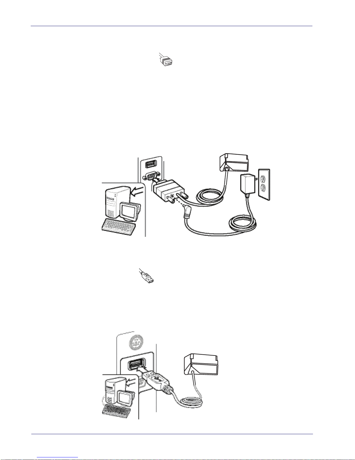
Setup Attaching Reader to Host
Attaching Reader to Host
RS-232 Serial Connection
Turn off power to the terminal/PC and connect the reader to the terminal/PC serial port via the
RS-232 cable as shown in
Terminal) to supply reader power, use the approved power supply
Adapter barrel connector into the socket on the RS-232 cable connector and the AC Adapter
plug into a standard power outlet.
Figure 1. RS-232 Connection
Figure 1
. If the terminal will not support POT (Power Off the
(AC Adapter). Plug the AC
USB Connection
Connect the reader to a USB port on the terminal/PC. Reference
Figure 2. USB connection
Figure 2
.
14
Gryphon™ I GFS4400
Page 17

Interface Selection Setup
Interface Selection
Since your scanner should have shipped with the correct interface cable (RS-232 or USB), the
interface type should already be defined. If you need to change the interface type, go to Table 1
starting on page 16
Each reader model will support one of the following sets of host interfaces:
GFS4450-9 Model GFS4470 Model
• RS-232-STD
• RS-232 Wincor-Nixdorf
If your installation requires you to select options to customize your reader, turn to the
appropriate
(also listed beside each interface type in
and scan the appropriate bar code in that section.
• USB-COM, USB-OEM, USB-KBD,
USB_KBD-ALT
s
ection for your interface type in
Unlike some programming features and options, interface selections
require that you scan only one programming bar code label. DO NOT
scan an ENTER/EXIT bar code prior to scanning an interface selection bar
code.
"Configuration Using Bar Codes" starting on page 21
Tab le 1 on page 16
).
, USB-KBD-Apple
Some interfaces require the scanner to star
powered up. If additional scanner configuration is desired while in this
state, pull the trigger and hold it for five seconds. The scanner will
change to a state that allows programming with bar codes.
t in the disabled state when
Product Reference Guide
15
Page 18
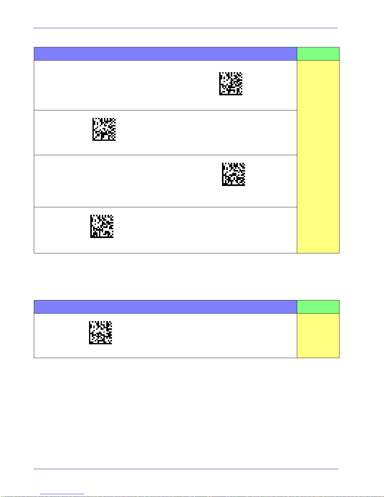
Setup Interface Selection
$P,HA12,P(CR)
$P,HA13,P(CR)
$P,HA47,P(CR)
$P,HA45,P(CR)
Table 1. Available Interfaces
RS-232 FEATURES
RS-232 standard interface
Select RS232-STD
Select RS232-WN
RS-232 for use with OPOS/UPOS/JavaPOS
RS-232 Wincor-Nixdorf
Set RS-232
Interface
Features
starting on
page 25
Select RS-232 OPOS
USB Com to simulate RS-232 standard interface
Select USB-COM-STD
a. Download the correct USB Com driver from www.adc.datalogic.com
a
USB-OEM FEATURES
Select USB-OEM
USB-OEM
(can be used for OPOS/UPOS/JavaPOS)
Set USB-OEM
Interface
Features
starting on
page 47
16
Gryphon™ I GFS4400
Page 19
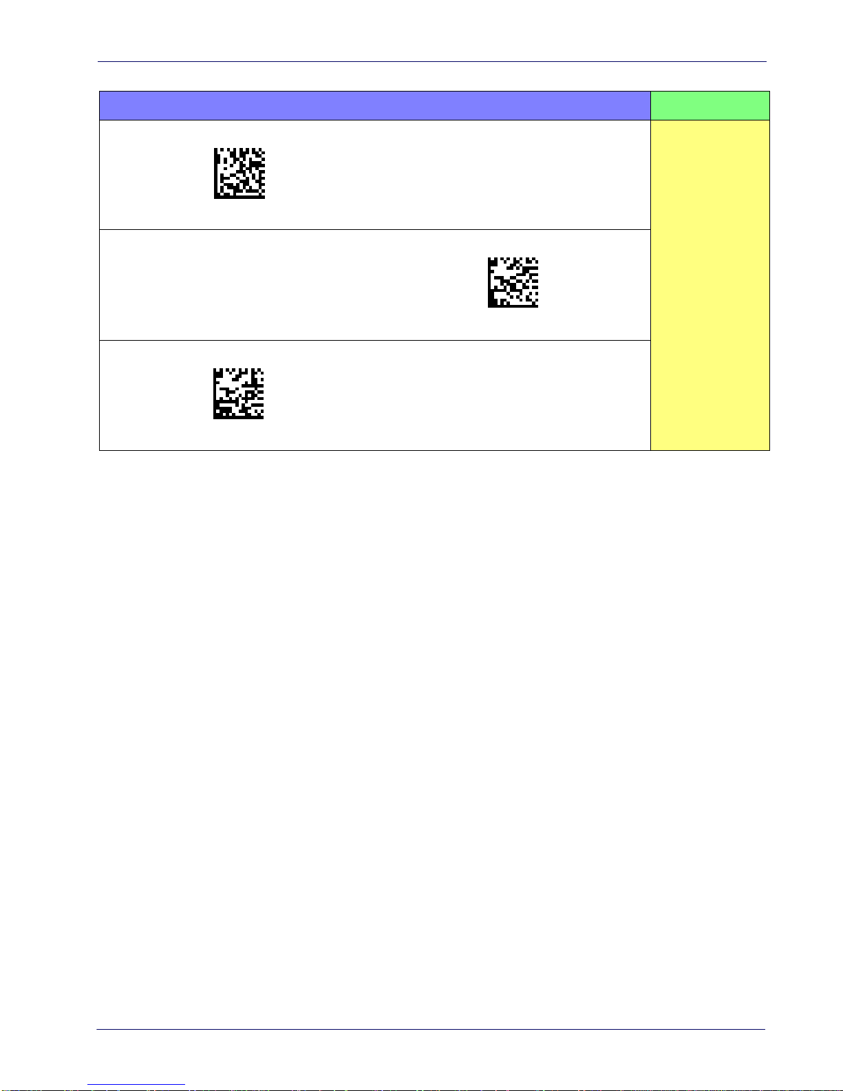
$P,HA35,P(CR)
$P,HA2C,P(CR)
$P,HA2B,P(CR)
Interface Selection Setup
KEYBOARD FEATURES
USB Keyboard with standard key encoding
Select USB Keyboard
Set KEYBOARD
Interface
USB Keyboard for Apple computers
Select USB-KBD-APPLE
USB Keyboard with alternate key encoding
Select USB Alternate Keyboard
Features
starting on page 37
Product Reference Guide
17
Page 20

Setup Custom Configuration Settings
Transmit Software Version
RevA
Custom Configuration Settings
Configure Interface Settings
If your installation requires you to select options to customize your reader, turn to the
appropriate section for your interface type in
•
"RS-232 Only Interface" on page 25
•
"RS-232/USB-Com Interfaces" on page 30
•
"USB Keyboard Settings" on page 37
Global Interface Features
See "
Global Interface Features" on page 23
Configuring Other Features
If your installation requires different programming than the standard factory default settings,
the following sections of this manual allow configuration of non-interface-specific settings you
might require:
"Configuration Using Bar Codes" starting on page 21
for settings configurable by all interface types.
.
Reading Parameters
:
Reading Parameters include programming for scanning, beeper and LED
indicators and other universal settings.
Symbologies
:
Includes options concerning the bar code label types (symbologies). These settings
allow you to enable/disable symbologies, set label lengths, require check digit, etc.
Software Version Transmission
The software version of the device can be transmitted over the interface by scanning the
following label.
18
Gryphon™ I GFS4400
Page 21

Custom Configuration Settings Setup
Restore Custom Default Configuration
$P,HA00,P(CR)
$P,AE,P(CR)
$P,Ae,P(CR)
Resetting the Product Configuration to Defaults
Restore Custom Defaults
If you aren’t sure what programming options are in your imager, or you’ve changed some
options and want to restore the Custom Default Configuration that may have been saved in the
scanner, scan the Restore Custom Default Configuration bar code below. This will restore the
custom configuration for the currently active interface.
Custom defaults are based on the interface type. Configure the imager
for the correct interface before scanning this label.
Restore Factory Configuration
If you want to restore the Factory Configuration for your imager, scan either the Restore USA
Factory Configuration bar code or the Restore EU Factory Configuration bar code below. Both
labels restore the scanner configuration to the factory settings, including the interface type. The
USA label restores Label IDs to those historically used in the USA. The EU label restores Label
IDs to those historically used in Europe. The Label ID sets for USA and EU are shown in the
“Label ID Control” section on page 57
of this manual.
Restore USA Factory Configuration
The programming items listed in the following sections show the factory default settings for
each of the menu commands.
Product Reference Guide
Restore EU Factory Configuration
19
Page 22

Setup Custom Configuration Settings
NOTES
20
Gryphon™ I GFS4400
Page 23

Configuration Using Bar Codes
This and following sections provide programming bar codes to configure your reader by
changing the default settings. For details about additional methods of programming, see
"Configuration Methods" on page 11.
Configuration Parameters
Once the reader is set up, you can change the default parameters to meet your application needs.
Refer to "Standard Defaults" starting on page 289 for initial configuration in order to set the
default values and select the interface for your application.
Chapter 3
You must first enable your reader to read bar codes in order to use this
section. If you have not done this, go to
complete the appropriate procedure.
Setup, starting on page 13
and
The following configuration parameters are divided into logical
the desired function based on its reference group.
groups, making it easy to find
Interface Configuration:
• "Global Interface Features" on page 23
• "RS-232 Only Interface" on page 25
• "RS-232/USB-Com Interfaces" on page 30
• "USB Keyboard Settings" on page 37
• "USB-OEM Interface" on page 47
Parameters common to all interface applications:
• "Data Format" on page 51 gives options to control the messages sent to the Host system.
• "Reading Parameters" on page 73 control various operating modes and indicators status
functioning.
Symbology-specific parameters:
• "Symbologies" on page 93 provides configuration of a personalized mix of 1D codes, code
families and their options.
• "2D Symbologies" on page 185 provides configuration of a personalized mix of 2D codes,
code families and their options.
Product Reference Guide
21
Page 24

Enter/Exit Programming Mode
To program features:
1. Scan the ENTER/EXIT PROGRAMMING bar code, available at the top of each programming page, when applicable.
2. Scan the bar code to set the desired programming feature. You may need to cover unused
bar codes on the page, and possibly the facing page
the bar code you intend to scan.
3. If additional input parameters are needed, go to Appendix E, Keypad, and scan the appropriate characters from the keypad.
You must first enable your reader to read bar codes in order to use this
section. If you have not done this, go to
complete the appropriate procedure.
Setup, starting on page 13
and
, to ensure that the reader reads only
Additional information about many features can be found in the “References” chapter.
If you make a mistake before the last character, scan the CANCEL bar code
a
bort and not save the entry string. You can then start again at the
to
beginning.
4. Complete the programming sequence by scanning the ENTER/EXIT PROGRAMMING bar code to exit Programming Mode.
For more detailed descriptions, programming information and examples
for setting selected
configuration items, see References, starting on page 243.
22
Gryphon™ I GFS4400
Page 25
Enter/Exit Programming Mode
DEFAULT
$CIFIH00(CR)
$CIFIH01(CR)
GLOBAL INTERFACE FEATURES
The following interface features are configurable by all interface types.
Host Commands — Obey/Ignore
This option specifies whether the reader will obey or ignore host commands. When set to
ignore, the reader will ignore all host commands except for those necessary for:
•service mode
• flash programming mode
• keeping the interface active
• transmission of labels.
Host Commands = Obey
(Do Not Ignore Host Commands)
Host Commands = Ignore
Product Reference Guide
23
Page 26

Enter/Exit Programming Mode
NOTES
24
Gryphon™ I GFS4400
Page 27

RS-232 ONLY INTERFACE
BAUD RATE on page 26
DATA BITS on page 27
STOP BITS on page 27
PARITY on page 28
HANDSHAKING CONTROL on page 29
Use the programming bar codes in this section if modific
interface settings are necessary to meet your system’s requirements. Additional settings
which apply to both the RS-232 and USB interfaces are available in the next section, "RS-
232/USB-Com Interfaces" starting on page 30.
Reference Appendix C, Standard Defaults for a listing of standard factory settings.
ations to the standard RS-232
Product Reference Guide
25
Page 28
Enter/Exit Programming Mode RS-232 Only Interface
$CR2BA00(CR)
$CR2BA01(CR)
$CR2BA02(CR)
$CR2BA03(CR)
DEFAULT
$CR2BA04(CR)
$CR2BA05(CR)
$CR2BA06(CR)
$CR2BA07(CR)
Baud Rate
See page 244 for information on this feature.
Baud Rate = 1200
Baud Rate = 2400
Baud Rate = 4800
Baud Rate = 9600
Baud Rate = 38,400
Baud Rate = 19,200
Baud Rate = 57,600
Baud Rate = 115,200
26
Gryphon™ I GFS4400
Page 29

RS-232 Only Interface Enter/Exit Programming Mode
$CR2DA00(CR)
$CR2DA01(CR)
$CR2ST00(CR)
$CR2ST01(CR)
Data Bits
This parameter allows the reader to interface with devices requiring a 7-bit or 8-bit ASCII
protocol for sending and receiving data.
7 Data Bits
DEFAULT
8 Data Bits
Stop Bits
Set the number of stop bits to match host device requirements. See page 244 for more
information on this feature.
DEFAULT
1 Stop Bit
2 Stop Bits
Product Reference Guide
27
Page 30
Enter/Exit Programming Mode RS-232 Only Interface
$CR2PA00(CR)
$CR2PA01(CR)
$CR2PA02(CR)
Parity
This feature specifies parity required for sending and receiving data. Select the parity type
according to host device requirements. See page 244 for more information.
DEFAULT
Parity = None
Parity = Even
Parity = Odd
28
Gryphon™ I GFS4400
Page 31

RS-232 Only Interface Enter/Exit Programming Mode
$CR2HC00(CR)
$CR2HC01(CR)
$CR2HC02(CR)
$CR2HC03(CR)
$CR2HC04(CR)
Handshaking Control
See page 244 for more information about this feature.
DEFAULT
Handshaking Control = RTS
Handshaking Control = RTS/CTS
Handshaking Control = RTS/XON/XOFF
Handshaking Control = RTS On/CTS
Handshaking Control = RTS/CTS Scan Control
Product Reference Guide
29
Page 32

RS-232/USB-COM INTERFACES
INTERCHARACTER DELAY on page 31
BEEP ON ASCII BEL on page 31
BEEP ON NOT ON FILE on page 32
ACK NAK OPTIONS on page 32
ACK CHARACTER on page 33
NAK CHARACTER on page 33
ACK NAK TIMEOUT VALUE on page 34
ACK NAK RETRY COUNT on page 34
ACK NAK ERROR HANDLING on page 35
INDICATE TRANSMISSION FAILURE on page 35
DISABLE CHARACTER on page 36
ENABLE CHARACTER on page 36
The programming bar codes in this chapter allow modification
USB-Com interfaces. Reference Appendix C, Standard Defaults for a listing of standard factory
settings.
s to the standard RS-232 and
Product Reference Guide
30
Page 33

RS-232/USB-Com Interfaces Enter/Exit Programming Mode
$CR2IC00(CR)
$CR2IC
~
00 = No Intercharacter Delay
$CR2BB00(CR)
$CR2BB01(CR)
Intercharacter Delay
This parameter specifies the intercharacter delay between the end of one character and the
beginning of the next. The delay can be set within a range of zero (0) to 990 milliseconds in
10ms increments. A setting of zero specifies no delay.
Intercharacter Delay = No Delay
To configure this feature, scan the ENTER/EXIT
PROGRAMMING MODE bar code above, then the
bar code at left followed by the digits from the
Alphanumeric characters in Appendix E, Keypad
Select Intercharacter Delay Setting
Make a mistake? Scan the CANCEL bar code to abort
and not save the entry string. You can then start again at
the beginning.
representing your desired character(s). End by
scanning the ENTER/EXIT
bar code again.
CANCEL
DEFAULT
Beep On ASCII BEL
When this parameter is enabled, the reader issues a beep when a <BEL> character is detected on
the RS-232 serial line. <BEL> is issued to gain a user's attention to an illegal entry or other
important event.
DEFAULT
Beep On ASCII BEL = Disable
Product Reference Guide
Beep On ASCII BEL = Enable
31
Page 34

Enter/Exit Programming Mode RS-232/USB-Com Interfaces
$CBPNF00(CR)
DEFAULT
$CBPNF01(CR)
$CR2AE00(CR)
$CR2AE01(CR)
$CR2AE02(CR)
$CR2AE03(CR)
Beep On Not on File
This option enables/disables the action of the reader to sound a three beep sequence upon
receiving a Not-On-File (NOF) host command.
Beep On Not On File = Disable
Beep On Not On File = Enable
ACK NAK Options
This enables/disables the ability of the reader to support the RS-232 ACK/NAK protocol.
See page 246 for more information.
DEFAULT
ACK/NAK Protocol = Enable for label transmission
ACK/NAK Protocol = Enable for label transmission and
host-command acknowledge
ACK/NAK Protocol = Disable ACK/NAK
ACK/NAK Protocol = Enable for host-command
acknowledge
32
Gryphon™ I GFS4400
Page 35

RS-232/USB-Com Interfaces Enter/Exit Programming Mode
$CR2AC
0x06 ‘ACK’ Character
$CR2NA
0x15 ‘NAK’ Character
ACK Character
This setting specifies an ASCII character or hex value to be used as the ACK character. ASCII
characters or any hex value from 0 to 0xFF can be selected. See page 246 for more information.
Setting to previously defined characters such as XON, XOFF, or host commands conflicts with normal
operation of these characters. 8-bit data is not recognized when the option
7 Data Bits.
Select ACK Character Setting
Data Bits
has been set as
DEFAULT
NAK Character
This setting specifies an ASCII character or hex value to be used as the NAK character. ASCII
characters or any hex value from 0 to 0xFF can be selected.
Setting to previously defined characters such as XON, XOFF, or host commands conflicts with normal
operation of these characters. 8-bit data is not recognized when the option
7 Data Bits.
Select NAK Character Setting
See page 247 for more information.
Data Bits
has been set as
DEFAULT
Product Reference Guide
33
Page 36

Enter/Exit Programming Mode RS-232/USB-Com Interfaces
$CR2AT
~
DEFAULT
01 ACK NAK Timeout value is 200ms
$CR2AR
~
003 = 3 Retries
ACK NAK Timeout Value
This option specifies the amount of time the reader waits for an ACK character from the host
following label transmission. The selectable timeout range is 200 milliseconds to 15,000ms (15
seconds) in 200ms increments. A selection of 0 disables the timeout.
See page 248 for more information on setting th
Select ACK NAK Timeout Value Setting
Make a mistake? Scan the CANCEL bar code to
not save the entry string. You can then start again at the
beginning.
abort and
ACK NAK Retry Count
This feature specifies the number of times the reader retries a label transmission due to a retry
condition. The selectable range is from 1 to 254 retries. A selection of 0 disables the count, and
a selection of 255 specifies unlimited retries. See page 249 for more information.
is feature.
To configure this feature, scan the ENTER/EXIT
PROGRAMMING MODE bar code above, then the
bar code at left followed by the digits from the
Alphanumeric characters in Appendix E, Keypad
representing your desired character(s). End by
scanning the ENTER/EXIT
bar code again.
CANCEL
Select ACK NAK Retry Count Setting
Make a mistake? Scan the CANCEL bar code to
not save the entry string. You can then start again at the
beginning.
DEFAULT
34
abort and
To configure this feature, scan the ENTER/EXIT
PROGRAMMING MODE bar code above, then the
bar code at left followed by the digits from the
Alphanumeric characters in Appendix E, Keypad
representing your desired character(s). End by
scanning the ENTER/EXIT
bar code again.
CANCEL
Gryphon™ I GFS4400
Page 37

RS-232/USB-Com Interfaces Enter/Exit Programming Mode
$CR2EH00(CR)
$CR2EH01(CR)
$CR2EH02(CR)
$CR2TF00(CR)
$CR2TF01(CR)
ACK NAK Error Handling
This feature specifies the method the reader uses to handle receive errors detected while waiting
for an ACK character from the host.
DEFAULT
ACK NAK Error Handling = Ignore Errors Detected
ACK NAK Error Handling = Process Error as Valid ACK
Character
Indicate Transmission Failure
This option enables/disables the reader’s ability to sound an error beep to indicate a
transmission failure while in ACK/NAK mode
Indicate Transmission Failure = Enable Indication
ACK NAK Error Handling = Process Error as
Valid NAK Character
.
Indicate Transmission Failure = Disable Indication
DEFAULT
Product Reference Guide
35
Page 38

Enter/Exit Programming Mode RS-232/USB-Com Interfaces
$CR2DC
0x44 = Disable Character is ‘D’
$CR2EC
0x45 = Enable Character is ‘E’
Disable Character
Specifies the value of the RS-232 host command used to disable the reader.
ASCII characters or any hex value from 0 to
Setting to previously defined characters such as XON, XOFF, or host commands conflicts with
normal operation of these characters. 8-bit data is not recognized when the option
has been set as 7 Data Bits.
See page 250 for more information on setting this feature.
Select Disable Character Setting
DEFAULT
0xFF can be selected.
Data Bits
Enable Character
Specifies the value of the RS-232 host command used to enable the reader.
ASCII characters or any hex value from 0 to
Setting to previously defined characters such as XON, XOFF, or host commands conflicts with
normal operation of these characters. 8-bit data is not recognized when the option
has been set as 7 Data Bits.
See page 251 in “References” for more information on setting this feature.
Select Enable Character Setting
0xFF can be selected.
DEFAULT
Data Bits
36
Gryphon™ I GFS4400
Page 39

USB KEYBOARD SETTINGS
COUNTRY MODE on page 38
SEND CONTROL CHARACTERS on page 42
INTERCODE DELAY on page 43
CAPS LOCK STATE on page 43
USB KEYBOARD SPEED on page 44
USB KEYBOARD NUMERIC KEYPAD on page 45
Use the programming bar codes in this chapter to select options for USB Keyboard
Interface. Reference Appendix C, Standard Defaults for a listing of standard factory
settings.
Information about control character emulation which applie
listed in Appendix G, Scancode Tables.
s to keyboard interfaces is
Product Reference Guide
37
Page 40

Enter/Exit Programming Mode USB Keyboard Settings
$CKBCO00(CR)
$CKBCO01(CR)
$CKBCO02(CR)
$CKBCO11(CR)
$CKBCO0E(CR)
$CKBCO03(CR)
Country Mode
This feature specifies the country/language supported by the keyboard. Several languages are
supported:
DEFAULT
Country Mode = U.S.
Country Mode = Belgium
Country Mode = Croatia
Supports only the interfaces listed in the Country
Mod
e feature description.
Country Mode = Denmark
Country Mode = Britain
Supports only the interfaces listed in the Country
Mode feature description.
Country Mode = Czech Republic
Supports only the interfaces listed in the Country Mode
feature description.
38
Gryphon™ I GFS4400
Page 41

USB Keyboard Settings Enter/Exit Programming Mode
$CKBCO04(CR)
$CKBCO13(CR)
$CKBCO05(CR)
$CKBCO0D(CR)
$CKBCO06(CR)
$CKBCO0C(CR)
Country Mode (continued)
Country Mode = France
Supports only the interfaces listed in the Country Mode feature description.
Country Mode = French Canadian
Country Mode = Germany
Supports only the interfaces listed in the Country Mode feature description.
Country Mode = Italy
Supports only the interfaces listed in the Country Mode feature description.
Country Mode = Hungary
Country Mode = Japanese 106-key
Product Reference Guide
39
Page 42

Enter/Exit Programming Mode USB Keyboard Settings
$CKBCO14(CR)
$CKBCO07(CR)
$CKBCO12(CR)
$CKBCO08(CR)
$CKBCO10(CR)
$CKBCO0F(CR)
Country Mode (continued)
Supports only the interfaces listed in the Country Mode
fe
ature description.
Country Mode = Lithuanian
Country Mode = Norway
Supports only the interfaces listed in the Country Mode
feature description.
Country Mode = Poland
Supports only the interfaces listed in the Country Mode feature description.
Country Mode = Romania
Supports only the interfaces listed in the Country Mode feature description.
Country Mode = Portugal
Supports only the interfaces listed in the Country
Mode f
eature description.
Country Mode = Slovakia
40
Gryphon™ I GFS4400
Page 43

USB Keyboard Settings Enter/Exit Programming Mode
$CKBCO09(CR)
$KBCO0A(CR)
$CKBCO0B(CR)
Country Mode (continued)
Country Mode = Spain
Country Mode = Sweden
Supports only the interfaces listed in the Country
Mode feature description.
Country Mode = Switzerland
Product Reference Guide
41
Page 44

Enter/Exit Programming Mode USB Keyboard Settings
$CKBSC00(CR)
$CKBSC01(CR)
$CKBSC02(CR)
Send Control Characters
This feature specifies how the reader transmits ASCII control characters to the host. Reference
Appendix G, Scancode Tables for more information about control characters.
Options are as follows:
Control Character 00 :
special keys are located from 0x80 to 0xA1.
Control Character 01 :
special keys are located from 0x80 to 0xA1.
Control Character 02 :
0xFE are intended as an extended ASCII table (see "Microsoft Windows Codepage 1252" on
page 317).
Characters from 00 to 0x1F are sent as control character Ctrl+Keys,
Characters from 00 to 0x1F are sent as control character Ctrl+Shift,
Special keys are located from 00 to 0x1F and characters from 0x80 to
DEFAULT
Reader Send Control Characters = 01
Reader Send Control Characters = 00
42
Reader Send Control Characters = 02
Gryphon™ I GFS4400
Page 45

USB Keyboard Settings Enter/Exit Programming Mode
$CKBID
~
DEFAULT
00 = No Intercode Delay
$CKBCL00(CR)
$CKBCL01(CR)
$CKBCL02(CR)
Intercode Delay
Specifies the delay between labels transmitted to the host for this interface. The selectable range
for this feature is from 0 to 99 seconds.
See page 252 in “References” for detailed information and examples for setting this feature.
Set Intercode Delay
Make a mistake? Scan the CANCEL bar code to
abort and
not save the entry string. You can then start again at the
beginning.
Caps Lock State
This option specifies the format in which the reader sends character data. This does not apply
when an alternate key encoding keyboard is selected.
To configure this feature, scan the ENTER/EXIT PROGRAMMING MODE bar code above, then the bar code at left followed by the digits from the Alphanumeric characters in
Appendix E, Keypad representing your desired charac-
ter(s). End by scanning the ENTER/EXIT bar code again.
CANCEL
DEFAULT
Caps Lock State = Caps Lock ON
Product Reference Guide
Caps Lock State = Caps Lock OFF
Caps Lock State = AUTO Caps Lock Enable
43
Page 46

Enter/Exit Programming Mode USB Keyboard Settings
$CKBSP01(CR)
$CKBSP02(CR)
$CKBSP03(CR)
$CKBSP04(CR)
$CKBSP05(CR)
$CKBSP06(CR)
USB Keyboard Speed
This option specifies the USB poll rate for a USB keyboard.
This feature applies ONLY to the USB Keyboard interface.
DEFAULT
USB Keyboard Speed = 1ms
USB Keyboard Speed = 2ms
USB Keyboard Speed = 4ms
USB Keyboard Speed = 6ms
USB Keyboard Speed = 3ms
USB Keyboard Speed = 5ms
44
Gryphon™ I GFS4400
Page 47

$CKBSP07(CR)
$CKBSP08(CR)
$CKBSP09(CR)
$CKBSP0A(CR)
USB Keyboard Settings Enter/Exit Programming Mode
$CKBKP00(CR)
$CKBKP01(CR)
USB Keyboard Speed (continued)
USB Keyboard Speed = 7ms
USB Keyboard Speed = 8ms
USB Keyboard Speed = 9ms
USB Keyboard Speed = 10ms
USB Keyboard Numeric Keypad
This option Controls whether numeric characters will be sent using standard keys or the
numeric keypad.
DEFAULT
Standard Keys
Numeric Keypad
Product Reference Guide
45
Page 48

Enter/Exit Programming Mode USB Keyboard Settings
NOTES
46
Gryphon™ I GFS4400
Page 49

USB-OEM INTERFACE
USB-OEM DEVICE USAGE on page 48
TRANSMIT LABELS IN CODE 39 FORMAT on page 49
INTERFACE OPTIONS on page 49
Feature settings for USB interfaces differ depending upon which host type the reader will be
connected with. Us
OEM interface. Other USB interfaces are included in the appropriate chapter for their host
type.
Reference Appendix C for a listing of standard factory settings.
e the feature settings in this chapter to specifically configure for the USB-
Product Reference Guide
47
Page 50

Enter/Exit Programming Mode USB-OEM Interface
$CIBUT00(CR)
$CIBUT01(CR)
DEFAULT
USB-OEM Device Usage
The USB-OEM protocol allows for the reader to be identified as one of two different types of
bar code scanners. Depending on what other scanners you may already have connected to a
USB-OEM POS, you may need to change this setting to enable all devices to communicate.
Options are:
• Table Top Scanner
• Handheld Scanner
It may be necessary to switch device usage when connecting two readers/scanners of the same
type to a POS system.
USB-OEM Device Usage = Handheld Scanner
USB-OEM Device Usage = Table Top Scanner
48
Gryphon™ I GFS4400
Page 51

USB-OEM Interface
$CIBC300(CR)
$CIBC301(CR)
$CIFO101(CR)
$CIFO102(CR)
DEFAULT
Transmit Labels in Code 39 Format
This feature enable/disables translation to Code 39 before transmitting label data to a USBOEM host. Only the symbology identifier is modified for the translation. The data is not
converted to Code 39 or verified to be valid for Code 39.
Options are:
Code 39 Format:
• USB-OEM: Code128, Code 93, and Codabar
Translate the following symbologies to Code 39:
DEFAULT
Transmit Labels in Code 39 Format = Code 39 Format
Interface Options
This feature provides for an interface-specific control mechanism.
Transmit Labels in Code 39 Format =
IBM Standard Format
Ignore Scanner Configuration Host Commands
Product Reference Guide
Obey Scanner Configuration Host Commands
49
Page 52

USB-OEM Interface
NOTES
50
Gryphon™ I GFS4400
Page 53

DATA FORMAT
GLOBAL PREFIX/SUFFIX on page 52
GLOBAL AIM ID on page 53
SET AIM ID INDIVIDUALLY FOR GS1-128 on page 55
LABEL ID starting on page 56
•Label ID: Pre-Loaded Sets
•Individually Set Label ID
•Label ID Control
•Label ID Symbology Selection • 1D Symbologies
•Label ID Symbology Selection • 2D Symbologies
NO READ MESSAGE starting on page 63
NO READ STRING starting on page 63
CODE VERIFIER MODE starting on page 64
•Code Verifier Mode
•Match String
•Wrong Co de Stri ng
CASE CONVERSION on page 67
CHARACTER CONVERSION on page 67
The features in this chapter can be used to build specific user-defined data
string. See “References” starting on page 254 for more detailed instructions on setting these
features.
Reference Appendix C for a listing of standard factory settings.
into a message
Product Reference Guide
51
Page 54

Enter/Exit Programming Mode Data Format
$CLFPR
$CLFSU
~
DEFAULT
No Global Prefix
Global Suffix = 0x0D (CR)
Global Prefix/Suffix
This option sets up to 20 characters each from the set of ASCII characters or any hex value from
00 to FF. The characters may be added as a prefix (in a position before the bar code data, also
called a header) and/or as a suffix (in a position following the bar code data, also called a footer).
See page 255 for more detailed instructions on setting th
is feature.
To configure this feature, scan the ENTER/EXIT PROGRAMMING MODE ba
to place the unit in Programming Mode, then the “Set Global Prefix” or “Set Global Suffix,”
bar code followed by the digits (in hex) from the Alphanumeric characters in Appendix E
Keypad representing your desired character(s). If l
are selected, scan the ENTER/EXIT bar code to terminate the s
by scanning the ENTER/EXIT bar code again.
Set Global Suffix
Make a mistake? Scan the CANCEL bar code to abort and not
save the entry string. You can then start again at the beginning.
r code above
ess than the expected string of 20 characters
tring. Exit programming mode
Set Global Prefix
CANCEL
52
Gryphon™ I GFS4400
Page 55

Data Format Enter/Exit Programming Mode
$CAIEN00(CR)
$CAIEN01(CR)
Global AIM ID
This feature enables/disables addition of AIM IDs for all symbology
types.
AIM label identifiers (as opposed to custom characters you select yourself as with label
identifiers) can be included with scanned bar code data. See Table 2 on page 3-53 for a listing of
AIM IDs.
AIM label identifiers consist of three characters as follows:
• A close brace character (ASCII ‘]’), followed by...
• A code character (see some samples in the table below), followed by...
• A modifier character (the modifier character is symbol dependent).
DEFAULT
Global AIM ID = Disable
Global AIM ID = Enable
Table 2
Tag Name
ABC CODABAR X 58
ANKER PLESSEY N 4E
AZTEC z 7A
CHINA SENSIBLE CODE X 58
CODABAR F 46
CODE11 H 48
CODE128 C 43
CODE32 A 41
CODE39 A 41
CODE39 CIP X 58
CODE39 DANISH PPT X 58
CODE39 LAPOSTE X 58
CODE39 PZN X 58
CODE93 G 47
DATABAR 14 e 65
DATABAR 14 COMPOSITE e 65
DATABAR EXPANDED e 65
. AIM IDs
AIM ID code
character
AIM ID code
ASCII value
Product Reference Guide
53
Page 56

Enter/Exit Programming Mode Data Format
DATABAR EXPANDED
COMPOSITE e 65
DATABAR LIMITED e 65
DATABAR LIMITED COMPOSITE e 65
DATA MATRIX d 64
EAN128 C 43
EAN128 COMPOSITE C 43
EAN13 E 45
EAN13 P2 E 45
EAN13 P5 E 45
EAN13 COMPOSITE E 45
EAN8 E 45
EAN8 P2 E 45
EAN8 P5 E 45
EAN8 COMPOSITE E 45
FOLLET 2OF5 X 58
I2OF5 I 49
IATA INDUSTRIAL 2OF5 X 58
INDUSTRIAL 2OF5 X 58
ISBN X 58
ISBT128 CONCAT X 58
ISSN X 58
MAXICODE U 55
MICRO QR Q 51
MICRO PDF L 4C
MSI M 4D
PDF417 L 4C
PLESSEY P 50
POSTAL AUSTRALIAN X 58
POSTAL IMB X 58
POSTAL JAPANESE X 58
POSTAL KIX X 58
POSTAL PLANET X 58
POSTAL PORTUGAL X 58
POSTAL POSTNET BB X 58
POSTAL ROYAL MAIL X 58
POSTAL SWEDISH X 58
POSTNET X 58
QR CODE Q 51
S25 S 53
TRIOPTIC X 58
UPCA E 45
UPCA P2 E 45
UPCA P5 E 45
UPCA COMPOSITE E 45
UPCE E 45
UPCE P2 E 45
UPCE P5 E 45
UPCE COMPOSITE E 45
54
Gryphon™ I GFS4400
Page 57

Data Format Enter/Exit Programming Mode
$CU8AI00(CR)
$CU8AI01(CR)
DEFAULT
Set AIM ID Individually for GS1-128
This feature configures a Label ID individually for the GS1-128 symbology and the
programming for this works the same way as Label ID. See Label ID: Set Individually Per
Symbology, starting on page 260 for detailed instructions on se
Set AIM ID Individually for GS1-128 = Disable
Set AIM ID Individually for GS1-128 = Enable
tting this feature.
Product Reference Guide
55
Page 58

Data Format
$P,AE,P\r
$P,Ae,P\r
Label ID
A Label ID is a customizable code of up to three ASCII characters (convert to Hex using the
ASCII Chart on the inside back cover of this manual), used to identify a bar code symbology
type. It can be appended previous to or following the transmitted bar code data depending upon
how this option is enabled. This feature provides options for configuring custom Label IDs or
individually per symbology (see "Individually Set Label ID" on page 57). If you wish to
program the reader to always include an industry standard label identifier for ALL symbology
types,
see the previous feature "Global AIM ID" on page 53.
See Label ID, starting on page 257 of “References” for more information on setting this feature.
Label ID: Pre-Loaded Sets
The reader supports two pre-loaded sets of Label IDs. See Label ID: Pre-loaded Sets, starting on
page 257 for details on the USA set and EU set.
Unlike some programming features and options,
scan only one programming bar code label. DO NOT scan an ENTER/EXIT bar
code prior to scanning the bar codes below.
When changing from one Label ID set to another, all other reader configuration
settings, including the host interface type, will be erased and set to the standard factory defaults. Any custom configuration or custom defaults will be lost.
CAUTION
DEFAULT
Label ID Pre-loaded Set = EU Set
this feature requires that you
Label ID Pre-loaded Set = USA Set
56
Gryphon™ I GFS4400
Page 59

Data Format Enter/Exit Programming Mode
$CIDCO00(CR)
$CIDCO01(CR)
$CIDCO02(CR)
Individually Set Label ID
This feature configures a Label ID individually for a single symbology. To set, first define
whether you want it as a prefix or suffix by scanning a label below. Then turn to Label ID
Symbology Selection • 1D Symbologies, starting on page 58 to select the symbology you want
to set, followed by up to 3 characters from the ASCII Chart at th
"Label ID: Set Individually Per Symbology" on page 260 f
feature.
or detailed instructions on setting this
e back of this manual. See
Label ID Control
This option controls whether a Label ID is disabled, or sent as a prefix or suffix for a given
symbology type.
DEFAULT
Label ID Transmission = Disable
Label ID Transmission = Enable as Prefix
Label ID Transmission = Enable as Suffix
Product Reference Guide
57
Page 60

Enter/Exit Programming Mode Data Format
$CACID
$CP3ID
$CALID
$CC9ID
$CPAID
$CI8ID
$CCBID
$CDPID
$CC1ID
$C3BID
$CC8ID
$C3MID
$CC3ID
$C32ID
Label ID Symbology Selection − 1D Symbologies
This option selects the symbology for which a Label ID is to be configured. See "Label ID" on
page 56 or page 260 in “References” for more detailed instructions.
If less than the expected string of 3 characters are selected, scan the ENTER/
EXIT bar code twice to accept the selection and exit Programming Mode.
Set ABC Codabar Label ID Character(s)
Set Anker Plessey Label ID Character(s)
Set Australian Postal Code Label ID Character(s)
Set Codabar Label ID Character(s)
Set Code 11 Label ID Character(s)
Set Code 32 Pharmacode Label ID Character(s)
Set Code 93 Label ID Character(s)
Set Concatenated ISBT 128 Label ID Character(s)
Set Danish PPT Label ID Character(s)
Set EAN 13 Label ID Character(s)
Set Code 128 Label ID Character(s)
Set Code 39 Label ID Character(s)
58
Set EAN 13 Composite Label ID Character(s)
Set EAN 13 P2 Label ID Character(s)
Gryphon™ I GFS4400
Page 61

Data Format Enter/Exit Programming Mode
$CCCID
$C35ID
$C8BID
$CXCID
$C8MID
$CU8ID
$C82ID
$CUMID
$C85ID
$CLBID
$CF2ID
$CLCID
$C4BID
$CG2ID
$C4CID
$CG5ID
Label ID Symbology Selection − 1D Symbologies (continued)
Set Code 39 CIP Label ID Character(s)
Set EAN 8 Label ID Character(s)
Set EAN 8 Composite Label ID Character(s)
Set EAN 8 P2 Label ID Character(s)
Set EAN 13 P5 Label ID Character(s)
Set GS1 DataBar Expanded Composite
Label ID Character(s)
Set GS1-128 Label ID Character(s)
Set GS1-128 Composite Label ID Character(s)
Set EAN 8 P5 Label ID Character(s)
Set Follett 2 of 5 Label ID Character(s)
Set GS1 DataBar 14 Label ID Character(s)
Set GS1 DataBar 14 Composite Label ID Character(s)
Set GSI DataBar Limited Label ID Character(s)
GSI DataBar Limited Composite Label ID Character(s)
Set GTIN 2 Label ID Character(s)
Set GTIN 5 Label ID Character(s)
Product Reference Guide
59
Page 62

Enter/Exit Programming Mode Data Format
$CXBID
$CGBID
$CIAID
$CLPID
$CPMID
$CMSID
$CU2ID
$CPPID
$CI2ID
$CPLID
$CISID
$CPGID
$CINID
$CPNID
$CPJID
$CPKID
Label ID Symbology Selection − 1D Symbologies (continued)
Set GS1 DataBar Expanded Label ID Character(s)
Set IATA Industrial 2 of 5 Label ID Character(s)
Set IMB Postal Code Label ID Character(s)
Set Industrial 2 of 5 Label ID Character(s)
Set Interleaved 2 of 5 Label ID Character(s)
Set GTIN 8 Label ID Character(s)
Set LaPoste Code 39 Label ID Character(s)
Set MSI Label ID Character(s)
Set Planet Postal Code Label ID Character(s)
Set Plessey Label ID Character(s)
Set ISBN Label ID Character(s)
Set ISSN Label ID Character(s)
Set Japan Postal Code Label ID Character(s)
60
Set Portugal Postal Code Label ID Character(s)
Set Postnet Label ID Character(s)
Set Kix Postal Code Label ID Character(s)
Gryphon™ I GFS4400
Page 63

Data Format Enter/Exit Programming Mode
$CPZID
$CPBID
$CPRID
$CAMID
$CS2ID
$CA2ID
$CPSID
$CA5ID
$CCTID
$CEBID
$CABID
$CE5ID
Label ID Symbology Selection − 1D Symbologies (continued)
Set PZN Code Label ID Character(s)
Set Royal Postal Code Label ID Character(s)
Set Standard 2 of 5 Label ID Character(s)
Set Swedish Postal Code Label ID Character(s)
Set Trioptic Code Label ID Character(s)
Set Postnet BB Label ID Character(s)
Set UPC-A Composite Label ID Character(s)
Set UPC-A P2 Label ID Character(s)
Set UPC-A P5 Label ID Character(s)
Set UPC-E Label ID Character(s)
Set UPC-A Label ID Character(s)
Product Reference Guide
Set UPC-E P5 Label ID Character(s)
61
Page 64

$CAZID
$CMXID
$CCSID
$CP4ID
$CCFID
$CMIID
$CDMID
$CQRID
$CMQID
Enter/Exit Programming Mode Data Format
Label ID Symbology Selection − 2D Symbologies
Set Aztec Label ID Character(s)
Set China Sensible Label ID Character(s)
Set Codablock F Label ID Character(s)
Set Data Matrix Label ID Character(s)
Set Micro QR Label ID Character(s)
Set Maxicode Label ID Character(s)
Set PDF 417 Label ID Character(s)
Set Micro PDF 417 Label ID Character(s)
Set QR Code Label ID Character(s)
62
Gryphon™ I GFS4400
Page 65

Data Format Enter/Exit Programming Mode
$CNRSS00\r
DEFAULT
$CNRSS01\r
$CNORS
~
DEFAULT
0x18 = (CAN)
No Read Message
This feature Enables/Disables the No Read Message feature. When Disabled, nothing is sent if
the trigger is pressed and released when no code has been decoded during a reading phase.
Otherwise, the No Read String is sent. (See "No Read String" on page 263 to configure No
Read String
data)
Disabled
Enabled
No Read String
This feature defines the string or character to be displayed in case of No Read during a reading
phase (On Line and Serial On Line Modes only). It allows up to 20 characters, from the set of
ASCII characters or any hex value from 00 to FE.
Select No Read String
Make a mistake? Scan the CANCEL barcode to abort and not
a
ve the entry string. You can then start again at the beginning.
s
To configure this feature, scan th
e ENTER/EXIT PROGRAMMING
MODE barcode above, then the barcode at left followed by the
digits (in hex) from the Alphanumeric characters in
E Keypad
representing your desired character(s). If less than
Appendix
the expected string of 20 characters are selected, scan the
ENTER/EXIT b
arcode to terminate the string.End by scanning
the ENTER/EXIT barcode again.
CANCEL
See "No Read String" on page 263 for more information on setting this feature.
Product Reference Guide
63
Page 66

Enter/Exit Programming Mode Data Format
$CLFCV00
DEFAULT
$CLFCV01
$CLFCV02
CODE VERIFIER
This feature allows the scanner to verify that all codes read and decoded match a defined string
saved in its memory. It is valid when in On Line, Serial On Line, Automatic and Automatic
(Object Sense) Operating Modes.
If the code read matches the code verifier Match String, then it is sent to the host through the
configured port. If it does not match th
send either the Wrong Code or a defined Wrong String message to indicate the error.
e code verifier Match String, you can specify whether to
See "Code Verifier" on page 263
in References for more information about these features.
Code Verifier Mode
Disable or specify parameters for Code Verifier Mode. See "Code Verifier Mode" on page 263
in References for more information.
Disabled
Transmit Wrong Code
Transmit Wrong String
64
Gryphon™ I GFS4400
Page 67

Data Format Enter/Exit Programming Mode
$CCOVS
~
$CWCVS
~
Match String
This feature allows you to define the string to be used as the match code for Code Verification.
The Match String must be configured to include start/stop characters and check digits if their
transmission is enabled. See "Match String" on page 263 in References for more information
It is possible to define the Match string by inserting:
•
all printable characters
• non printable ASCII characters
No wild card characters are supported.
.
Set Match String
Make a mistake? Scan the CANCEL barcode to abort and not
sa
ve the entry string. You can then start again at the beginning.
Wrong Code String
See "Wrong Code String" on page 264 in References for more information about this feature.
Set Wrong Code String
To configure this feature, scan th
e ENTER/EXIT PROGRAMMING
MODE barcode above, then the barcode at left followed by the
digits (in hex) from the Alphanumeric characters in
E Keypad
representing your desired character(s). End by
Appendix
scanning the ENTER/EXIT barcode again.
CANCEL
To configure this feature, scan the ENTER/EXIT PROGRAMMING
MODE barcode above, then the barcode at left followed by the
digits (in hex) from the Alphanumeric characters in
E Keypad
representing your desired character(s). End by
Appendix
scanning the ENTER/EXIT barcode again.
Make a mistake? Scan the CANCEL barcode to abort and not
ve the entry string. You can then start again at the beginning.
sa
Product Reference Guide
CANCEL
65
Page 68

Enter/Exit Programming Mode Data Format
$CLFTX00\r
$CLFTX01\r
Label Transmit Mode
Specifies whether the decoded label must be transmitted to the host as it has been decoded or
after the reading phase has been deactivated (Phase Off).
Phase Off
DEFAULT
On Decode
Advanced Formatting: User Label Edit
Advanced formatting is available to create user label edit scripts. See the Datalogic Aladdin
configuration application or contact Technical Support.
66
Gryphon™ I GFS4400
Page 69

Data Format Enter/Exit Programming Mode
$CLFCA00(CR)
$CLFCA01(CR)
$CLFCA02(CR)
$CLFCH
0xFFFFFFFFFFFFFFFF
(No character conversion)
Case Conversion
This feature allows conversion of the case of all alphabetic characters to upper or lower case.
Case conversion affects ONLY scanned bar code data, and does not affect Label
ID, Prefix, Suffix, or other appended data.
DEFAULT
Case Conversion = Disable (no case conversion)
Case Conversion = Convert to upper case
Case Conversion = Convert to lower case
Character Conversion
Character conversion is an eight byte configuration item. The eight bytes are 4 character pairs
represented in hexadecimal ASCII values. The first character in the pair is the character that will
be converted. The second character in the pair is the character to convert to. If the character to
convert in a pair is FF, then no conversion is done.
If less than the expected string of 16 characters are selected, scan the ENTER/
EXIT bar code twice to accept the selections and exit Programming Mode.
Configure Character Conversion
DEFAULT
Product Reference Guide
67
Page 70

Enter/Exit Programming Mode Data Format
NOTES
68
Gryphon™ I GFS4400
Page 71

DIGITAL OUTPUT
Digital Output only pertains to the GFS4450-9 RS232 interface.
ACTIVATION EVENT on page 70
DEACTIVATION EVENT on page 71
DEACTIVATION TIMEOUT on page 71
ACTIVATION STATE on page 72
See “References” starting on page 254 for more information about Digital Output.
Use the programming barcodes in this chapter to select options for
Appendix C, for a listing of standard factory settings.
Digital Outputs. Reference
Product Reference Guide
69
Page 72

Enter/Exit Programming Mode Digital Output
$COUA100\r
DEFAULT
$COUA101\r
$COUA102\r
$COUA103\r
Activation Event
Defines the event activating the output.
Disable
Good Read
No Read
Wrong Code
70
Gryphon™ I GFS4400
Page 73

Digital Output Enter/Exit Programming Mode
$COUD100\r
DEFAULT
$COUD101\r
$COUD102\r
$COUT1
~
005 = 500 msec
Deactivation Event
Defines the event deactivating the output. See "Wrong Code String" on page 264 in
“References” for more information about this feature.
Disable
Reading Phase Active
Timeout
Deactivation Timeout
When Timeout is the selected Deactivation Event, this specifies the maximum duration of the
output pulse.
Set Deactivation Timeout
Make a mistake? Scan the CANCEL barcode to abort and not
ve the entry string. You can then start again at the begin-
sa
ning.
DEFAULT
To configure this feature, scan the ENTER/EXIT PROGRAMMING MODE barcode above, then the barcode at left followed by the digits (in hex) from the Alphanumeric
char
acters in Appendix E, Keypad representing your
desired character(s). Exit programming mode by scanning
the ENTER/EXIT barc
ode again.
CANCEL
Product Reference Guide
71
Page 74

Enter/Exit Programming Mode Digital Output
$COUL100\r
DEFAULT
$COUL101\r
Activation State
Determines the active state of the output.
Closed
Open
72
Gryphon™ I GFS4400
Page 75

READING PARAMETERS
DOUBLE READ TIMEOUT on page 74 GOOD READ BEEP FREQUENCY on page 76
LED AND BEEPER INDICATORS on page 75 GOOD READ BEEP LENGTH on page 77
POWER ON ALERT on page 75 GOOD READ BEEP VOLUME on page 78
GOOD READ: WHEN TO INDICATE on page 75 GOOD READ LED DURATION on page 79
GOOD READ BEEP TYPE on page 76
SCANNING FEATURES
OPERATING MODE on page 80 AIMING POINTER on page 86
PHASE OFF EVENT on page 81 AIMING DURATION TIMER on page 87
PHASE OFF TIMEOUT on page 81 GREEN SPOT DURATION on page 87
SERIAL START CHARACTER on page 82 MOBILE PHONE MODE on page 88
SERIAL STOP CHARACTER on page 82 MOBILE BIAS on page 88
PRESENTATION MODE INDICATION on page 83 PARTIAL LABEL READING CONTROL on page 89
MANUAL TRIGGER CONTROL on page 83 MIRROR READING MODE on page 89
CENTRAL CODE ONLY on page 84 DECODE NEGATIVE IMAGE on page 90
ILLUMINATION OFF TIME on page 84 IMAGE CAPTURE on page 90
ILLUMINATION ON TIME on page 85 MULTIPLE LABELS PER FRAME on page 91
SCANNING ACTIVE TIME on page 85
PRESENTATION ILLUMINATION CONTROL on
page 86
MULTIPLE LABELS ORDERING BY CODE SYM-
BOLOGY on page 92
MULTIPLE LABELS ORDERING BY CODE LENGTH
on page 92
Product Reference Guide
73
Page 76

Enter/Exit Programming Mode Reading Parameters
$CSNDR0A(CR)
$CSNDR32(CR)
$CSNDR64(CR)
$CSNDR
~
Double Read Timeout
Double Read Timeout specifies the minimum time between consecutive good reads of labels of
the same symbology and data. This prevents a double read of the same label. If the unit reads a
label and sees the same label again within the specified timeout, the second read is ignored.
Double Read Timeout does not apply to scan modes that require a trigger pull for each label
read. The timeout can be set within a range of 20 milliseconds to 2,550 milliseconds (2.55
seconds) in 10ms increments.
Double Read Timeout = 0.1 Second
Double Read Timeout = 1 Second
To specify your own setting, scan the bar code below followed by the appropriate characters
from Appendix E, Keypad. See page 266 in “References” for detailed instructions and examples
for setting this feature.
Select Double Read Timeout Setting
Make a mistake? Scan the CANCEL bar code to abort and
not save the entry string. You can then start again at the
beginning.
Double Read Timeout = 0.5 Second
DEFAULT
CANCEL
74
Gryphon™ I GFS4400
Page 77

Reading Parameters Enter/Exit Programming Mode
$CBPPU00(CR)
$CBPPU01(CR)
$CBPIN00(CR)
$CBPIN01(CR)
$CBPIN02(CR)
LED AND BEEPER INDICATORS
Power On Alert
Disables or enables the indication (from the Beeper) that the reader is receiving power.
Power On Alert = Disable (No Audible Indication)
DEFAULT
Power On Alert = Power-up Beep
Good Read: When to Indicate
This feature specifies when the reader will provide indication (beep and/or flash its green LED)
upon successfully reading a bar code.
DEFAULT
Indicate Good Read = After Transmit
Indicate Good Read = After Decode
Indicate Good Read =
After CTS goes inactive then active
Product Reference Guide
75
Page 78

Enter/Exit Programming Mode Reading Parameters
$CBPTY00(CR)
$CBPTY01(CR)
$CBPFR00(CR)
$CBPFR01(CR)
$CBPFR02(CR)
Good Read Beep Type
Specifies whether the good read beep has a mono or bitonal beep sound.
DEFAULT
Good Read Beep Type = Mono
Good Read Beep Type = Bitonal
Good Read Beep Frequency
Adjusts the good read beep to sound at a selectable low, medium or high frequency, selectable
from the list below. (Controls the beeper’s pitch/tone.)
Good Read Beep Frequency = Medium
Good Read Beep Frequency = Low
DEFAULT
Good Read Beep Frequency = High
76
Gryphon™ I GFS4400
Page 79

Reading Parameters Enter/Exit Programming Mode
$CBPLE06(CR)
$CBPLE08(CR)
$CBPLE0A(CR)
$CBPLE0C(CR)
$CBPLE0E(CR)
$CBPLE10(CR)
$CBPLE12(CR)
$CBPLE14(CR)
Good Read Beep Length
Good Read Beep Length = 80 msec
Good Read Beep Length = 60 msec
DEFAULT
Good Read Beep Length = 100 msec
Good Read Beep Length = 120 msec
Good Read Beep Length = 160 msec
Good Read Beep Length = 200 msec
Good Read Beep Length = 140 msec
Good Read Beep Length = 180 msec
Product Reference Guide
77
Page 80

Enter/Exit Programming Mode Reading Parameters
$CBPVO00CR)
$CBPVO01CR)
$CBPVO02CR)
$CBPVO03CR)
Good Read Beep Volume
Selects the beeper volume (loudness) upon a good read beep. There are three selectable volume
levels.
Good Read Beep Volume = Beeper Off
Good Read Beep Volume = Low
Good Read Beep Volume = High
Good Read Beep Volume = Medium
DEFAULT
78
Gryphon™ I GFS4400
Page 81

Reading Parameters Enter/Exit Programming Mode
$CLAGL00(CR)
$CLAGL
~
003 = Good Read LED
stays on for 300 ms.
Good Read LED Duration
This feature specifies the amount of time that the Good Read LED remains on following a good
read. The good read LED on time can be set within a range of 100 milliseconds to 25,500
milliseconds (0.1 to 25.5 seconds) in 100ms increments. A setting of 00 keeps the LED on until
the next trigger push.
See page 267 in “References” for detailed instructions and examples for setting
Select Good Read LED Duration Setting
Make a mistake? Scan the CANCEL bar code to
abort and
not save the entry string. You can then start again at the
beginning.
this feature.
Good Read LED Duration Setting =
Keep LED on until next trigger push
To configure this feature, scan the ENTER/EXIT PROGRAMMING MODE bar code above, then the bar code at left followed by the digits from the Alphanumeric characters in
Appendix E, Keypad representing your desired charac-
ter(s). End by scanning the ENTER/EXIT bar code again.
CANCEL
DEFAULT
Product Reference Guide
79
Page 82

Enter/Exit Programming Mode Reading Parameters
$CSNRM00\r
$CSNRM01\r
$CSNRM02\r
DEFAULT
$CSNRM03\r
SCANNING FEATURES
Operating Mode
Selects the reader’s scan operating mode. See page 268 in “References” for descriptions.
On Line
Serial On Line
Automatic
Automatic (Object Sense)
80
Gryphon™ I GFS4400
Page 83

Reading Parameters Enter/Exit Programming Mode
$CSPTO00\r
$CSPTO01\r
$CSPTO02\r
$CSNET
~
5 = Timeout set for 5 seconds
Phase Off Event
DEFAULT
Trigger Stop
Timeout
Trigger Stop - Timeout
Phase Off Timeout
Timeout can be set within a range of 1second to 255 seconds in 1 second intervals.
Scanning Active Time
Make a mistake? Scan the CANCEL barcode to abort and not
e the entry string. You can then start again at the begin-
sav
ning.
DEFAULT
To configure this feature scan the ENTER/EXIT PROGRAMMING
MODE barcode above, then the barcode at left, followed by
the digits (in hex) from the Alphanumeric characters in
Appendix E, Keypad
ter(s). End by scanning the
representing your desired charac-
ENTER/EXIT barcode again.
CANCEL
Product Reference Guide
81
Page 84

Enter/Exit Programming Mode Reading Parameters
$CSTON
~
DEFAULT
0x02 = Serial Start Character is [02 STX]
$CSTOF
~
DEFAULT
0x03 = Serial Stop Character is [03 ETX]
Serial Start Character
See page 268 in “References” for more information.
To configure this feature scan the ENTER/EXIT PROGRAMMING
ove, then the barcode at left, followed by
representing your desired charac-
ENTER/EXIT barcode again.
CANCEL
Select Serial Start Characters
Make a mistake? Scan the CANCEL barcode to abort and not
e the entry string. You can then start again at the begin-
sav
ning.
MODE barcode ab
the digits (in hex) from the Alphanumeric characters in
Appendix E, Keypad
ter(s). End by scanning the
Serial Stop Character
See page 268 in “References” for more information.
Select Serial Stop Characters
Make a mistake? Scan the CANCEL barcode to abort and not
sav
e the entry string. You can then start again at the begin-
ning.
The Serial Start/Stop Characters must be different and must not contain
reserved characters (see
To configure this feature scan the ENTER/EXIT PROGRAMMING
MODE barcode above, then the barcode at left, followed by
the digits (in hex) from the Alphanumeric characters in
Appendix E, Keypad
ter(s). End by scanning the
Appendix F, Reserved Characters
representing your desired charac-
ENTER/EXIT barcode again.
CANCEL
)
82
Gryphon™ I GFS4400
Page 85

Reading Parameters Enter/Exit Programming Mode
$CSMFL00(CR)
$CSMFL01(CR)
$CSOTM00
$CSOTM01
Presentation Mode Indication
This operation is useful for indicating when the reader is in Automatic/Triggered Object Sense
Operating Mode. If enabled, the blue indicator will blink when Presentation Mode scanning is
active.
DEFAULT
Presentation Mode Indication = Enable
Presentation Mode Indication = Disable
Manual Trigger Control
This feature is available in Serial On Line mode only.
This feature is used to enable/disable manual trigger when the reader is in Serial On Line
reading mode.
• Enable: allows a manual trigger push to start
a reading phase.
• Disable: (default) locks out the trigger button and does not allow manual triggering to
start a r
eading phase. When disabled, the trigger can still be activated once by pressing and
holding the trigger for 5 seconds to enter Debug Mode.
DEFAULT
Manual Trigger Control = Disable
Manual Trigger Control = Enable
Product Reference Guide
83
Page 86

Enter/Exit Programming Mode Reading Parameters
$CSNPM00(CR)
$CSNPM01(CR)
$CSNOO
DEFAULT
0 milliseconds
Central Code Only
Specifies the ability of the reader to decode labels only when they are close to the center of the
aiming pattern. This allows the reader to accurately target labels when they are placed close
together, such as on a pick sheet.
See Appendix B, Aimer Calibration starting on page 285 for information about setting the
aiming coordinates.
This feature is not compatible with Multiple Labels Reading in a Volume.
DEFAULT
Central Code Only = Disable
Central Code Only = Enable
Illumination Off Time
This feature defines the amount of time illumination is kept OFF after Illumination ON
timeout. When illumination OFF expires, Object Sense is resumed. This configuration is
available in Automatic (Object Sense) only. Range is 0 millisecond to 25.5 milliseconds in 100
millisecond intervals.
Select Presentation Mode Time Setting
To configure this feature, scan the ENTER/EXIT PROGRAMMING MODE bar code above, then the bar code at left followed by the digits from the Alphanumeric characters in
Appendix E, Keypad representing your desired charac-
ter(s). End by scanning the ENTER/EXIT bar code again.
84
Gryphon™ I GFS4400
Page 87

Reading Parameters Enter/Exit Programming Mode
$CSNON
1 Second
$CSNET03(CR)
$CSNET05(CR)
DEFAULT
$CSNET08(CR)
Illumination On Time
Defines the amount of time illumination is kept ON after a label is decoded. If an object is
detected before Illumination ON expires, the timer is refreshed with the Object Gone timeout
value. Range is 0 millisecond to 25.5 milliseconds in 100 millisecond intervals.
This configuration is available in Automatic (Object Sense) only.
To configure this feature, scan the ENTER/EXIT PROGRAMMING MODE bar code above, then the bar code at left followed by the digits from the Alphanumeric characters in
Appendix E, Keypad representing your desired charac-
Select Presentation Mode Time Setting
ter(s). End by scanning the ENTER/EXIT bar code again.
DEFAULT
Scanning Active Time
This setting specifies the amount of time that the reader stays in scan ON state once the state is
entered. The range for this setting is from 1 to 255 seconds in 1-second increments. See
page 270 in “References” for further description of this feature.
Scanning Active Time works in On Line and Serial On Line Read modes as
the Timeout Phase Off Event. See also
.
81
Scanning Active Time = 5 seconds
"
Phase Off Timeout" on page
Scanning Active Time = 3 seconds
Scanning Active Time = 8 seconds
Product Reference Guide
85
Page 88

Enter/Exit Programming Mode Reading Parameters
DEFAULT
$CSMIL00(CR)
$CSMIL01(CR)
$CSMIL02(CR)
$CTAAP00(CR)
$CTAAP01(CR)
Presentation Illumination Control
Controls the illumination status while the reading mode is Automatic Trigger Object Sense
Operating Mode and the reader is attempting to detect objects.
Illumination Control = OFF
Illumination Control = ON
Illumination Control = Dim
Aiming Pointer
Enables/disables the aiming pointer for all symbologies.
Aiming Pointer = Enable
Aiming Pointer = Disable
DEFAULT
86
Gryphon™ I GFS4400
Page 89

Reading Parameters Enter/Exit Programming Mode
DEFAULT
LSTM00
LSTM
~
$CLSSP00(CR)
$CLSSP01(CR)
$CLSSP02(CR)
$CLSSP03(CR)
Aiming Duration Timer
Specifies the frame of time the aiming pointer remains on after decoding a label, when in On
Line or Serial On Line mode.The range for this setting is from 1 to 255 seconds in 1-second
increments. See page 271 in “References” for a description of this feature.
Aiming Off After Decoding
To configure, scan the ENTER/EXIT PROGRAMMING MODE
bar code above, then the bar code at left followed by the
digits from the Alphanumeric characters in Appendix E,
Keypad representing your desired character(s). End by
Set Aiming Duration Timer
scanning the ENTER/EXIT bar code.
Make a mistake? Scan the CANCEL bar code to
abort and
not save the entry string. You can then start again at the
beginning.
Green Spot Duration
Specifies the duration of the good read pointer beam after a good read.
Green Spot Duration = Short (300 msec)
CANCEL
Green Spot Duration = Disable (Green Spot is Off )
DEFAULT
Green Spot Duration = Long (800 msec)
Product Reference Guide
Green Spot Duration = Medium (500 msec)
87
Page 90

Enter/Exit Programming Mode Reading Parameters
$CSNPE00(CR)
$CSNPE01(CR)
DEFAULT
$CSILF00\r
$CSILF
~
Mobile Phone Mode
This mode is useful for scanning bar codes displayed on a mobile phone. Other options for this
feature can be configured using the Datalogic Aladdin application.
Mobile Phone Mode = Disable
DEFAULT
Mobile Phone Mode = Enable
Mobile Bias
This variable mode alters scan module operation, optimizing barcode scanning for reading from
mobile device displays rather than standard labels. The range for this setting is from 0 to 255.
Set Mobile Bias
Make a mistake? Scan the CANCEL bar code to
not save the entry string. You can then start again at the
beginning.
abort and
No Mobile Bias
To configure, scan the ENTER/EXIT PROGRAMMING MODE
bar code above, then the bar code at left followed by the
digits from the Alphanumeric characters in Appendix E,
Keypad representing your desired character(s). End by
scanning the ENTER/EXIT bar code.
CANCEL
88
Gryphon™ I GFS4400
Page 91

Reading Parameters Enter/Exit Programming Mode
IPPL00
DEFAULT
IPPL01
$P,CMREN00,P\r
$P,CMREN01,P\r
Partial Label Reading Control
Enable/Disable the option to ignore partial labels to be read within the boundary of the field of
view.
Partial Label Reading Control = Disable
Partial Label Reading Control = Enable
Mirror Reading Mode
Enable/Disable the ability to decode the mirror image of a bar code label. This feature pertains
mainly to 2D barcodes: Data Matrix, Maxicode, QR Code Aztec and PDF-417. All 1D codes
can be read backwards without changing settings.
Unlike some programming features and options, Mirror Reading Mode requires
that you scan only one programming bar code label. DO NOT scan an ENTER/
EXIT bar code prior to scanning a Mirror Reading Mode bar code.
When this feature is enabled, you will be unable to read other programming
labels in this manual.
CAUTION
Mirror Reading Mode = Disable
DEFAULT
Product Reference Guide
Mirror Reading Mode = Enable
89
Page 92

Enter/Exit Programming Mode Reading Parameters
$P,CIPVR00,P\r
$P,CI$PVR01,P\r
Decode Negative Image
Enable/Disable the ability to decode a negative image for all symbologies. When this feature is
enabled, you will be unable to read normally-printed labels or programming labels in this
manual. Scan the “Disable” bar code below to return the scanner to its default for this feature.
To set the reader to decode only 2D codes, go to "2D Normal/Inverse Symbol Control" on page
7.
18
For additional options, see the Al
Unlike some programming features and options, Decode Negative Image selections require that you scan only one programming bar code label. DO NOT scan
an ENTER/
When this feature is enabled, you will be unable to read other programming
labels in this manual.
CAUTION
Decode Negative Image = Disable
addin configuration application.
EXIT bar code prior to scanning a Decode Negative Image bar code.
DEFAULT
Image Capture
For information and a list of options for Image Capture, use the Datalogic Aladdin
configuration application, available for free download from the Datalogic website.
90
Decode Negative Image = Enable
Gryphon™ I GFS4400
Page 93

Reading Parameters
$CSNML00(CR)
$CSNML01(CR)
MULTIPLE LABEL READING
When the reader’s aiming system is activated by a trigger push or other method (depending on
the mode), it then acquires and processes each image in the area in front of it (the Volume). In
this case, the scanner stops processing the image once it decodes a label. If several labels are
present in the volume, only the first label encountered is decoded and sent.
When Multiple Reading Mode is enabled, the scanner keeps on processing the image until all
the labels present are decoded. The reader then
configured to do so) before transmitting it.
Multiple Labels per Frame
Specifies the ability of the reader to decode and transmit a set of code labels in a specific volume
and in a single frame of time. When in Multiple Labels per Frame the reader beeps and turns on
the good read LED indication for each code read in a frame.
sorts the data from all the bar codes (if
When Multiple Labels Mode is enabled, ISBT pairing, ABC Codabar pairing,
are not allowed.
DEFAULT
Multiple Labels per Frame = Enable
and composites
Multiple Labels per Frame = Disable
Product Reference Guide
91
Page 94

Reading Parameters
$CSNMS
~
000000000000 = Random order
$CSNMT00(CR)
$CSNMT01(CR)
$CSNMT02(CR)
Multiple Labels Ordering by Code Symbology
This feature allows you to specify the order multiple labels are transmitted by symbology type,
when Multiple Labels per Frame is enabled. See page 272 in “References” for detailed
information on setting this feature.
Select Symbologies for Multiple Labels Ordering
To configure this feature, scan the ENTER/EXIT PROGRAMMING MODE bar code above, then the bar code at left followed by the digits From the alphanumeric characters In
Appendix d
ter(s). End by scanning the enter/exit bar code again.
, keypad representing your desired Charac-
Make a mistake? Scan the CANCEL bar code to
not save the entry string. You can then start again at the
beginning.
abort and
DEFAULT
Multiple Labels Ordering by Code Length
Specifies the transmission ordering by code length, when Multiple Labels per Frame is enabled.
CANCEL
DEFAULT
Transmit Increasing Length Order
92
Multiple Labels Ordering = Disable
Transmit Decreasing Length Order
Gryphon™ I GFS4400
Page 95

1D Code Selection
The reader supports the following 1D symbologies (bar code types). See "2D Symbologies"
starting on page 185
chapter.
• Disable All Symbologies on page 94 • GS1-128 on page 132
• Code EAN/UPC on page 95 • Code ISBT 128 on page 133
• UPC-E on page 98 • Interleaved 2 of 5 (I 2 of 5) on page 136
• GTIN Formatting on page 101 • Interleaved 2 of 5 CIP HR on page 141
• EAN 13 (Jan 13) on page 102 • "Follett 2 of 5" on page 141
• ISSN on page 104 • Standard 2 of 5 on page 142
• EAN 8 (Jan 8) on page 105 • Industrial 2 of 5 on page 146
• UPC/EAN Global Settings on page 107 • Code IATA on page 150
• Add-Ons on page 109 • Codabar on page 151
• Code 39 on page 116 • ABC Codabar on page 157
• Trioptic Code on page 122 • Code 11 on page 160
• Code 32 (Ital Pharmaceutical Code) on page 122 • GS1 DataBar™ Omnidirectional on
• Code 39 CIP (French Pharmaceutical) on
page 124
• Code 39 Danish PPT on page 124 • GS1 DataBar™ Limited on page 170
• Code 39 LaPoste on page 125 • Code 93 on page 171
• Code 39 PZN on page
• Code 128 on page 126 • Plessey on page 181
SYMBOLOGIES
for 2D bar codes. Symbology-dependent options are included in each
page 164
• GS1 DataBar™ Expanded on page 165
125 • MSI on page 176
Default settings are indicated at each feature/option
Appendix C, Standard Defaults for a listing of the most widely used set of standard factory
settings. That section also provides sp
for your system.
To set most features:
1. Scan the ENTER/EXIT PROGRAMMING bar code at the top of applicable p
ming pages.
2. Scan the correct bar code to set the desired programming feature or parameter. You may
need to cov
the reader reads only the bar code you intend to scan.
3. If additional input parameters are needed, go to Appendix E, Keypad, and scan the appropriate characters from the keypad.
4. Complete the programming sequence by scanning the ENTER/EXIT PROGRAMMING bar code to exit Programming Mode.
er unused bar codes on the page, and possibly the facing page, to ensure that
Additional information about many features can be found in the “References”
chapter.
If you make a mistake before the last character, scan the CANCEL bar code to abort
sa
and not
ve the entry string. You can then start again at the beginning.
ace to record any custom settings needed or implemented
with a green arrow. Also reference
rogram-
Product Reference Guide
93
Page 96

Enter/Exit Programming Mode Symbologies
$AD(CR)
DISABLE ALL SYMBOLOGIES
Use this feature to disable all symbologies.
1. Scan the ENTER/EXIT PROGRAMMING Mode bar code.
2. Scan the Disable All Symbologies bar code.
y
3. Complete the programming sequence b
MING bar code.
Disable All Symbologies
scanning the ENTER/EXIT PROGRAM-
This does not disable the reading of programming labels.
94
Gryphon™ I GFS4400
Page 97

Symbologies Enter/Exit Programming Mode
$CCPLC00(CR)
$CCPLC01(CR)
DEFAULT
$CCPLC02(CR)
CODE EAN/UPC
Coupon Control
This feature is used to control the reader’s method of processing coupon labels.
Coupon Control = Allow all coupon bar codes to be
decoded
Coupon Control = Enable only UPCA coupon decoding
Coupon Control = Enable only GS1 DataBar™
coupon decoding
Product Reference Guide
95
Page 98

Enter/Exit Programming Mode Symbologies
$CABEN00(CR)
$CABEN01(CR)
DEFAULT
$CABCT00(CR)
$CABCT01(CR)
DEFAULT
UPC-A
The following options apply to the UPC-A symbology.
UPC-A Enable/Disable
When disabled, the reader will not read UPC-A bar codes.
UPC-A = Disable
UPC-A = Enable
UPC-A Check Character Transmission
Enable this option to transmit the check character along with UPC-A bar code data.
UPC-A Check Character Transmission = Send
UPC-A Check Character Transmission = Don’t Send
96
Gryphon™ I GFS4400
Page 99

Symbologies Enter/Exit Programming Mode
$CAB3B00(CR)
$CAB3B01(CR)
$CABNS00(CR)
$CABNS01(CR)
DEFAULT
Expand UPC-A to EAN-13
Expands UPC-A data to the EAN-13 data format. Selecting this feature also changes the
symbology ID to match those required for EAN-13.
DEFAULT
UPC-A to EAN-13 = Don’t Expand
UPC-A to EAN-13 = Expand
UPC-A Number System Character Transmission
This feature enables/disables transmission of the UPC-A number system character.
UPC-A Number System Character = Transmit
UPC-A Number System Character = Do not transmit
Product Reference Guide
97
Page 100

Enter/Exit Programming Mode Symbologies
$CAB2D00(CR)
$CAB2D01(CR)
$CEBEN00(CR)
$CEBEN01(CR)
DEFAULT
UPC-A 2D Component
This feature enables/disables a requirement that a 2D label component be decoded when a base
label of this symbology is decoded.
DEFAULT
EAN-13 2D Component =
Disable (2D component not required)
EAN-13 2D Component =
2D component must be decoded
UPC-E
The following options apply to the UPC-E symbology.
UPC-E Enable/Disable
When disabled, the reader will not read UPC-E bar codes.
UPC-E = Enable
UPC-E = Disable
98
Gryphon™ I GFS4400
 Loading...