

Page 1
Gryphon
Fixed Mount Linear Imager
Bar Code Reader
™
I GFS4100
Product Reference Guide
Page 2

Datalogic Scanning, Inc.
959 Terry Street
Eugene, Oregon 97402
USA
Telephone: (541) 683-5700
Fax: (541) 345-7140
An Unpublished Work - All rights reserved. No part of the contents of this documentation or the procedures
described ther
ein may be reproduced or transmitted in any form or by any means without prior written permission
of Datalogic Scanning, Inc. or its subsidiaries or affiliates ("Datalogic" or “Datalogic Scanning”). Owners of Datalogic
products are hereby granted a non-exclusive, revocable license to reproduce and transmit this documentation for
the purchaser's own internal business purposes. Purchaser shall not remove or alter any proprietary notices, including copyright notices, contained in this documentation and shall ensure that all notices appear on any reproductions of the documentation.
Should future revisions of this manual be published, you can acquir
e printed versions by contacting your Datalogic
representative. Electronic versions may either be downloadable from the Datalogic website (www.scanning.datalogic.com) or provided on appropriate media. I
f you visit our website and would like to make comments or sugges-
tions about this or other Datalogic publications, please let us know via the "Contact Datalogic" page.
Disclaimer
Datalogic has taken reasonable measures to provide informa
ever, Datalogic reserves the right to change any specifica
Datalogic and the Datalogic logo are registered trademarks of Datal
tion in this manual that is complete and accurate, how-
tion at any time without prior notice.
ogic S.p.A. in many countries, including the
U.S.A and the E.U. All other brand and product names referred to herein may be trademarks of their respective owners.
Microsoft Windows®, Windows® XP and the Windows logo are registered trademarks of Microsoft Corporation.
Patents
This product is covered by one or more of the following patents.
US Pat.: 5,144,118; 5,311,000; 5,481,098
; 5,493,108; 5,929,421; 5,992,740; 6,098,883; 6,260,764; 6,443,360 B1;
6,631,846 B2; 6,808,114 B1; 6,817,525 B2; 6,997,385 B2; 7,075,663 B2; 7,387,246 B2.
European Pat.: 789,315 B1; 926,620 B1; 962,880 B1; 997,760 B1;
1,128,315 B1; 1,164,536 B1; 1,217,571 B1; 1,396,811
B1; 1,413,971 B1.
Additional patents pending.
Page 3

Table of Contents
INTRODUCTION ................................................................................................................................................................................ 7
About this Manual .......................................................................................................................................................................................... 7
Overview ....................................................................................................................................................................................................................................................7
Manual Conventions ............................................................................................................................................................................................................................. 7
References ....................................................................................................................................................................................................... 8
Technical Support .......................................................................................................................................................................................... 8
Datalogic Website Support ................................................................................................................................................................................................................. 8
Reseller Technical Support .................................................................................................................................................................................................................. 8
Telephone Technical Support ............................................................................................................................................................................................................ 8
About the Reader ........................................................................................................................................................................................... 8
Programming the Reader .............................................................................................................................................................................. 9
Configuration Methods ........................................................................................................................................................................................................................ 9
SETUP .............................................................................................................................................................................................. 11
Unpacking ..................................................................................................................................................................................................... 11
Setting Up the Reader .................................................................................................................................................................................. 11
Installing the Interface Cable ...................................................................................................................................................................... 12
Interface Selection ....................................................................................................................................................................................... 13
Setting the Interface ............................................................................................................................................................................................................................13
Customizing Configuration Settings .......................................................................................................................................................... 15
Configure Interface Settings ............................................................................................................................................................................................................15
Global Interface Features ...................................................................................................................................................................................................................15
Software Version Transmission .......................................................................................................................................................................................................15
Resetting Product Configuration to Defaults .............................................................................................................................................................................16
CONFIGURATION USING BARCODES ............................................................................................................................................ 17
Configuration Parameters .................................................................................................................................................................................................................17
Reading Configuration Barcodes ....................................................................................................................................................................................................18
GLOBAL INTERFACE FEATURES 19
Host Commands — Obey/Ignore .............................................................................................................................................................................19
RS-232 ONLY Interface ........................................................................................................................................................... 21
Baud Rate ...........................................................................................................................................................................................................................22
Data Bits .............................................................................................................................................................................................................................23
Stop Bits ..............................................................................................................................................................................................................................23
Parity ....................................................................................................................................................................................................................................24
Handshaking Control ....................................................................................................................................................................................................25
RS-232/USB-Com Interfaces................................................................................................................................................... 26
Intercharacter Delay .......................................................................................................................................................................................................27
Beep On ASCII BEL ..........................................................................................................................................................................................................27
Beep On Not on File .......................................................................................................................................................................................................28
ACK NAK Options ............................................................................................................................................................................................................28
ACK Character ..................................................................................................................................................................................................................29
NAK Character ..................................................................................................................................................................................................................29
ACK NAK Timeout Value ...............................................................................................................................................................................................30
ACK NAK Retry Count ....................................................................................................................................................................................................30
ACK NAK Error Handling ...............................................................................................................................................................................................31
Indicate Transmission Failure .....................................................................................................................................................................................31
Disable Character ............................................................................................................................................................................................................32
Enable Character .............................................................................................................................................................................................................32
USB Keyboard Interfaces ....................................................................................................................................................... 33
Country Mode ..................................................................................................................................................................................................................34
Send Control Characters ..............................................................................................................................................................................................37
USB Keyboard Speed .....................................................................................................................................................................................................38
Data Format ............................................................................................................................................................................ 41
Global Prefix/Suffix .........................................................................................................................................................................................................42
Global AIM ID ....................................................................................................................................................................................................................43
Product Reference Guide
1
Page 4

Contents
GS1-128 AIM ID ................................................................................................................................................................................................................44
Label ID ...............................................................................................................................................................................................................................44
Label ID: Pre-loaded Sets .............................................................................................................................................................................................44
Label ID: Set Individually Per Symbology ...............................................................................................................................................................45
Label ID Control ...............................................................................................................................................................................................................45
Label ID Symbology Selection ...................................................................................................................................................................................46
Set Global Mid Label ID Characters ..........................................................................................................................................................................50
No Read String .................................................................................................................................................................................................................51
CODE VERIFIER ............................................................................................................................................................................ 52
Code Verifier Mode .........................................................................................................................................................................................................52
Match String .....................................................................................................................................................................................................................53
Wrong Code String .........................................................................................................................................................................................................54
Case Conversion ..............................................................................................................................................................................................................54
Character Conversion ....................................................................................................................................................................................................55
Digital Output ......................................................................................................................................................................... 57
Activation Event ..............................................................................................................................................................................................................58
Deactivation Event .........................................................................................................................................................................................................59
Deactivation Timeout ....................................................................................................................................................................................................59
Activation State ...............................................................................................................................................................................................................60
Power Save.............................................................................................................................................................................. 61
USB Suspend Mode ........................................................................................................................................................................................................62
Sleep Mode Timeout .....................................................................................................................................................................................................63
Reading Parameters .............................................................................................................................................................. 65
Illumination Mode ..........................................................................................................................................................................................................66
LED AND BEEPER INDICATORS ................................................................................................................................................... 66
Power On Alert .................................................................................................................................................................................................................66
Good Read: When to Indicate .....................................................................................................................................................................................67
Good Read Beep ..............................................................................................................................................................................................................67
Good Read Beep Length ..............................................................................................................................................................................................68
Good Read LED Duration .............................................................................................................................................................................................69
Green Spot Duration ......................................................................................................................................................................................................70
LED Indication ..................................................................................................................................................................................................................70
SCANNING FEATURES .................................................................................................................................................................71
Operating Mode ..............................................................................................................................................................................................................71
Phase Off Event ................................................................................................................................................................................................................72
Phase Off Timeout ..........................................................................................................................................................................................................72
Serial Start Character .....................................................................................................................................................................................................73
Serial Stop Character .....................................................................................................................................................................................................73
Automatic Threshold .....................................................................................................................................................................................................74
Test Mode Multiple ........................................................................................................................................................................................................74
CAMERA CONTROL ...................................................................................................................................................................... 75
Exposure Mode ................................................................................................................................................................................................................75
Code Selection ........................................................................................................................................................................ 77
DISABLE ALL SYMBOLOGIES ...................................................................................................................................................... 78
CODE EAN/UPC ............................................................................................................................................................................ 79
Coupon Control ...............................................................................................................................................................................................................79
UPC-A ..................................................................................................................................................................................................................................80
UPC-A Enable/Disable ...................................................................................................................................................................................................80
UPC-A Check Character Transmission .....................................................................................................................................................................80
Expand UPC-A to EAN-13 .............................................................................................................................................................................................81
UPC-A Number System Character Transmission .................................................................................................................................................81
UPC-A Minimum Reads .................................................................................................................................................................................................82
UPC-E ............................................................................................................................................................................................ 83
UPC-E Enable/Disable ....................................................................................................................................................................................................83
UPC-E Check Character Transmission ......................................................................................................................................................................83
Expand UPC-E to EAN-13 .............................................................................................................................................................................................84
Expand UPC-E to UPC-A ...............................................................................................................................................................................................84
UPC-E Number System Character Transmission ..................................................................................................................................................85
UPC-E Minimum Reads .................................................................................................................................................................................................85
GTIN FORMATTING ...................................................................................................................................................................... 86
EAN 13 (JAN 13) ........................................................................................................................................................................... 87
EAN 13 Enable/Disable .................................................................................................................................................................................................87
2 Gryphon™ I GFS4170/GFS4150-9
Page 5

Contents
EAN 13 Check Character Transmission ...................................................................................................................................................................87
EAN-13 Flag 1 Character ...............................................................................................................................................................................................88
EAN-13 ISBN Conversion ..............................................................................................................................................................................................88
EAN 13 Minimum Reads ...............................................................................................................................................................................................89
ISSN .............................................................................................................................................................................................. 90
ISSN Enable/Disable .......................................................................................................................................................................................................90
EAN 8 (JAN 8) ............................................................................................................................................................................... 91
EAN 8 Enable/Disable ....................................................................................................................................................................................................91
EAN 8 Check Character Transmission ......................................................................................................................................................................91
Expand EAN 8 to EAN 13 ..............................................................................................................................................................................................92
EAN 8 Minimum Reads ..................................................................................................................................................................................................92
UPC/EAN GLOBAL SETTINGS ...................................................................................................................................................... 93
UPC/EAN Decoding Level ............................................................................................................................................................................................93
UPC/EAN Correlation .....................................................................................................................................................................................................94
UPC/EAN Price Weight Check .....................................................................................................................................................................................94
In-Store Minimum Reads ..............................................................................................................................................................................................95
ADD-ONS ...................................................................................................................................................................................... 96
Optional Add-ons ...........................................................................................................................................................................................................96
Optional Add-On Timer ................................................................................................................................................................................................97
Optional GS1-128 Add-On Timer ........................................................................................................................................................................... 100
P2 Add-Ons Minimum Reads ................................................................................................................................................................................... 103
P5 Add-Ons Minimum Reads ................................................................................................................................................................................... 104
GS1-128 Add-Ons Minimum Reads ....................................................................................................................................................................... 105
CODE 39 ...................................................................................................................................................................................... 106
Code 39 Enable/Disable ............................................................................................................................................................................................ 106
Code 39 Check Character Calculation .................................................................................................................................................................. 106
Code 39 Check Character Transmission .............................................................................................................................................................. 107
Code 39 Start/Stop Character Transmission ...................................................................................................................................................... 108
Code 39 Full ASCII ........................................................................................................................................................................................................ 108
Code 39 Quiet Zones .................................................................................................................................................................................................. 109
Code 39 Minimum Reads .......................................................................................................................................................................................... 110
Code 39 Decoding Level ...........................................................................................................................................................................................111
Code 39 Length Control ............................................................................................................................................................................................112
Code 39 Set Length 1 ................................................................................................................................................................................................. 113
Code 39 Set Length 2 ................................................................................................................................................................................................. 114
Code 39 Interdigit Ratio ............................................................................................................................................................................................. 115
Code 39 Character Correlation ................................................................................................................................................................................ 117
Code 39 Stitching ......................................................................................................................................................................................................... 117
CODE 32 (ITAL PHARMACEUTICAL CODE) ............................................................................................................................... 118
Code 32 Enable/Disable ............................................................................................................................................................................................ 118
Code 32 Feature Setting Exceptions .....................................................................................................................................................................118
Code 32 Check Char Transmission ........................................................................................................................................................................ 119
Code 32 Start/Stop Character Transmission ...................................................................................................................................................... 119
CODE 39 CIP (FRENCH PHARMACEUTICAL) .............................................................................................................................120
Code 39 CIP Enable/Disable ..................................................................................................................................................................................... 120
CODE 128 ................................................................................................................................................................................... 121
Code 128 Enable/Disable ..........................................................................................................................................................................................121
Expand Code 128 to Code 39 .................................................................................................................................................................................. 121
Code 128 Check Character Transmission ............................................................................................................................................................ 122
Code 128 Function Character Transmission ...................................................................................................................................................... 122
Code 128 Sub-Code Change Transmission ........................................................................................................................................................ 123
Code 128 Quiet Zones ................................................................................................................................................................................................ 124
Code 128 Minimum Reads ........................................................................................................................................................................................ 125
Code 128 Decoding Level .........................................................................................................................................................................................126
Code 128 Length Control .......................................................................................................................................................................................... 127
Code 128 Set Length 1 ...............................................................................................................................................................................................128
Code 128 Set Length 2 ...............................................................................................................................................................................................129
Code 128 Character Correlation .............................................................................................................................................................................130
Code 128 Stitching ...................................................................................................................................................................................................... 130
GS1-128 ...................................................................................................................................................................................... 131
GS1-128 Enable ............................................................................................................................................................................................................. 131
CODE ISBT 128 ........................................................................................................................................................................... 132
Product Reference Guide
3
Page 6

Contents
ISBT 128 Concatenation ............................................................................................................................................................................................ 132
ISBT 128 Concatenation Mode ................................................................................................................................................................................ 132
ISBT 128 Dynamic Concatenation Timeout ........................................................................................................................................................ 133
ISBT 128 Advanced Concatenation Options ...................................................................................................................................................... 133
INTERLEAVED 2 OF 5 (I 2 OF 5) ................................................................................................................................................. 134
I 2 of 5 Enable/Disable ................................................................................................................................................................................................ 134
I 2 of 5 Check Character Calculation ..................................................................................................................................................................... 134
I 2 of 5 Check Character Transmission .................................................................................................................................................................. 135
I 2 of 5 Minimum Reads ............................................................................................................................................................................................. 136
2 of 5 Decoding Level .................................................................................................................................................................................................137
I 2 of 5 Length Control ............................................................................................................................................................................................... 138
I 2 of 5 Set Length 1 ..................................................................................................................................................................................................... 139
I 2 of 5 Set Length 2 ..................................................................................................................................................................................................... 140
I 2 of 5 Character Correlation ................................................................................................................................................................................... 141
I 2 of 5 Stitching ............................................................................................................................................................................................................ 141
STANDARD 2 OF 5 ..................................................................................................................................................................... 142
Standard 2 of 5 Enable/Disable .............................................................................................................................................................................. 142
Standard 2 of 5 Check Character Calculation ....................................................................................................................................................142
Standard 2 of 5 Check Character Transmission ................................................................................................................................................. 143
Standard 2 of 5 Minimum Reads ............................................................................................................................................................................143
Standard 2 of 5 Decoding Level ............................................................................................................................................................................. 144
Standard 2 of 5 Length Control ..............................................................................................................................................................................144
Standard 2 of 5 Set Length 1 ................................................................................................................................................................................... 145
Standard 2 of 5 Set Length 2 ................................................................................................................................................................................... 146
Standard 2 of 5 Character Correlation .................................................................................................................................................................. 147
Standard 2 of 5 Stitching ........................................................................................................................................................................................... 147
INDUSTRIAL 2 OF 5 ....................................................................................................................................................................148
Industrial 2 of 5 Enable/Disable ..............................................................................................................................................................................148
Industrial 2 of 5 Check Character Calculation .................................................................................................................................................... 148
Industrial 2 of 5 Check Character Transmission ................................................................................................................................................149
Industrial 2 of 5 Length Control .............................................................................................................................................................................. 149
Industrial 2 of 5 Set Length 1 ................................................................................................................................................................................... 150
Industrial 2 of 5 Set Length 2 ................................................................................................................................................................................... 151
Industrial 2 of 5 Minimum Reads ............................................................................................................................................................................ 152
Industrial 2 of 5 Character Correlation ................................................................................................................................................................. 152
Industrial 2 of 5 Stitching .......................................................................................................................................................................................... 153
CODE IATA ..................................................................................................................................................................................154
IATA Enable/Disable ................................................................................................................................................................................................... 154
IATA Check Character Transmission ..................................................................................................................................................................... 154
DATALOGIC 2 OF 5 .................................................................................................................................................................... 155
Datalogic 2 of 5 Enable/Disable .............................................................................................................................................................................. 155
Datalogic 2 of 5 Check Character Calculation ................................................................................................................................................... 155
Datalogic 2 of 5 Minimum Reads ........................................................................................................................................................................... 156
Datalogic 2 of 5 Decoding Level ............................................................................................................................................................................. 156
Datalogic 2 of 5 Length Control .............................................................................................................................................................................157
Datalogic 2 of 5 Set Length 1 ................................................................................................................................................................................... 158
Datalogic 2 of 5 Set Length 2 ................................................................................................................................................................................... 159
Datalogic 2 of 5 Character Correlation ................................................................................................................................................................. 160
Datalogic 2 of 5 Stitching .......................................................................................................................................................................................... 160
CODABAR ...................................................................................................................................................................................161
Codabar Enable/Disable ............................................................................................................................................................................................ 161
Codabar Check Character Calculation .................................................................................................................................................................. 161
Codabar Check Character Transmission .............................................................................................................................................................. 162
Codabar Start/Stop Character Transmission ...................................................................................................................................................... 162
Codabar Start/Stop Character Set .......................................................................................................................................................................... 163
Codabar Start/Stop Character Match ...................................................................................................................................................................163
Codabar Quiet Zones .................................................................................................................................................................................................. 164
Codabar Minimum Reads ......................................................................................................................................................................................... 165
Codabar Decoding Level ........................................................................................................................................................................................... 166
Codabar Length Control ............................................................................................................................................................................................ 167
Codabar Set Length 1 ................................................................................................................................................................................................. 168
Codabar Set Length 2 ................................................................................................................................................................................................. 169
4 Gryphon™ I GFS4170/GFS4150-9
Page 7

Contents
Codabar Interdigit Ratio ............................................................................................................................................................................................ 170
Codabar Character Correlation ............................................................................................................................................................................... 172
Codabar Stitching ........................................................................................................................................................................................................ 172
ABC CODABAR ........................................................................................................................................................................... 173
ABC Codabar Enable/Disable .................................................................................................................................................................................. 173
ABC Codabar Concatenation Mode ...................................................................................................................................................................... 173
ABC Codabar Dynamic Concatenation Timeout .............................................................................................................................................. 174
GS1 DATABAR™ OMNIDIRECTIONAL ....................................................................................................................................... 175
GS1 DataBar™ Omnidirectional Enable/Disable ............................................................................................................................................... 175
GS1 DataBar™ Omnidirectional GS1-128 Emulation .......................................................................................................................................175
GS1 DataBar™ Omnidirectional Minimum Reads .............................................................................................................................................176
GS1 DATABAR™ EXPANDED .....................................................................................................................................................177
GS1 DataBar™ Expanded Enable/Disable ............................................................................................................................................................ 177
GS1 DataBar™ Expanded GS1-128 Emulation ................................................................................................................................................... 177
GS1 DataBar™ Expanded Minimum Reads .........................................................................................................................................................178
GS1 DataBar™ Expanded Length Control ........................................................................................................................................................... 178
GS1 DataBar™ Expanded Set Length 1 ................................................................................................................................................................. 179
GS1 DataBar™ Expanded Set Length 2 ................................................................................................................................................................. 180
GS1 DATABAR™ LIMITED ..........................................................................................................................................................181
GS1 DataBar™ Limited Enable/Disable ................................................................................................................................................................. 181
GS1 DataBar™ Limited GS1-128 Emulation ........................................................................................................................................................ 181
GS1 DataBar™ Limited Minimum Reads ..............................................................................................................................................................182
CODE 93 ...................................................................................................................................................................................... 183
Code 93 Enable/Disable ............................................................................................................................................................................................ 183
Code 93 Check Character Calculation .................................................................................................................................................................. 183
Code 93 Check Character Transmission .............................................................................................................................................................. 184
Code 93 Length Control ............................................................................................................................................................................................184
Code 93 Set Length 1 ................................................................................................................................................................................................. 185
Code 93 Set Length 2 ................................................................................................................................................................................................. 186
Code 93 Minimum Reads .......................................................................................................................................................................................... 187
Code 93 Decoding Level ...........................................................................................................................................................................................188
Code 93 Quiet Zones .................................................................................................................................................................................................. 189
Code 93 Character Correlation ................................................................................................................................................................................ 190
Code 93 Stitching ......................................................................................................................................................................................................... 190
MSI .............................................................................................................................................................................................. 191
MSI Enable/Disable ...................................................................................................................................................................................................... 191
MSI Check Character Calculation ...........................................................................................................................................................................191
MSI Check Character Transmission ........................................................................................................................................................................ 192
MSI Length Control ..................................................................................................................................................................................................... 192
MSI Set Length 1 ..........................................................................................................................................................................................................193
MSI Set Length 2 ..........................................................................................................................................................................................................194
MSI Minimum Reads ...................................................................................................................................................................................................195
MSI Decoding Level .................................................................................................................................................................................................... 196
MSI Stitching .................................................................................................................................................................................................................. 197
MSI Character Correlation ......................................................................................................................................................................................... 197
PLESSEY ...................................................................................................................................................................................... 198
Plessey Enable/Disable .............................................................................................................................................................................................. 198
Plessey Check Character Calculation .................................................................................................................................................................... 199
Plessey Check Character Transmission ................................................................................................................................................................ 199
Plessey Length Control .............................................................................................................................................................................................. 200
Plessey Set Length 1 ................................................................................................................................................................................................... 201
Plessey Set Length 2 ................................................................................................................................................................................................... 202
Plessey Minimum Reads ............................................................................................................................................................................................ 203
Plessey Decoding Level .............................................................................................................................................................................................204
Plessey Stitching .......................................................................................................................................................................................................... 205
Plessey Character Correlation ................................................................................................................................................................................. 205
SOFTWARE CONFIGURATION STRINGS ..................................................................................................................................... 207
Command Syntax .............................................................................................................................................................................................................................. 208
SERIAL CONFIGURATION STRINGS ......................................................................................................................................................................... 210
REFERENCES................................................................................................................................................................................. 233
RS-232 Parameters .....................................................................................................................................................................................233
Product Reference Guide
5
Page 8

Contents
RS-232 Only ......................................................................................................................................................................................................................................... 233
RS-232/USB COM Parameters .......................................................................................................................................................................................................234
Data Editing ................................................................................................................................................................................................241
Global Prefix/Suffix ...........................................................................................................................................................................................................................242
Global AIM ID ...................................................................................................................................................................................................................................... 243
Label ID .................................................................................................................................................................................................................................................244
Character Conversion ......................................................................................................................................................................................................................248
Scanner Data Formatting Control ...............................................................................................................................................................................................248
Reading Parameters ...................................................................................................................................................................................251
Illumination Mode ............................................................................................................................................................................................................................. 251
Good Read LED Duration ................................................................................................................................................................................................................ 251
Scanning Features ......................................................................................................................................................................................252
Operating Mode ................................................................................................................................................................................................................................ 252
On Line ............................................................................................................................................................................................................................. 252
Serial On Line ................................................................................................................................................................................................................. 252
Automatic ....................................................................................................................................................................................................................... 253
Automatic/Trigger Object Sense ............................................................................................................................................................................ 253
Test Mode ....................................................................................................................................................................................................253
Test Mode Multiple ........................................................................................................................................................................................................................... 254
Camera Control .................................................................................................................................................................................................................................. 254
Power Save .................................................................................................................................................................................................. 254
USB Suspend ....................................................................................................................................................................................................................................... 254
Sleep Mode Timeout ........................................................................................................................................................................................................................ 254
Digital Output .............................................................................................................................................................................................255
Symbologies ...............................................................................................................................................................................................255
Decoding Level ..................................................................................................................................................................................................................................255
Set Length ............................................................................................................................................................................................................................................ 255
TECHNICAL SPECIFICATIONS...................................................................................................................................................... 257
Standard Cable Pinouts ............................................................................................................................................................................. 259
LED and Beeper Indications .......................................................................................................................................................................260
Button and LED Status ..................................................................................................................................................................................................................... 260
Error Codes .................................................................................................................................................................................................. 261
STANDARD DEFAULTS................................................................................................................................................................ 263
SAMPLE BARCODES..................................................................................................................................................................... 273
KEYPAD ........................................................................................................................................................................................ 277
RESERVED CHARACTERS............................................................................................................................................................. 281
SCANCODE TABLES ..................................................................................................................................................................... 283
Control Character Emulation ..................................................................................................................................................................... 283
Single Press and Release Keys ....................................................................................................................................................................................................... 283
Interface Type USB-Keyboard or USB-Keyboard for APPLE ...................................................................................................................284
Interface type USB-Keyboard Alt Mode ................................................................................................................................................... 286
Microsoft Windows Codepage 1252 ......................................................................................................................................................... 288
INDEX........................................................................................................................................................................ 289
6 Gryphon™ I GFS4170/GFS4150-9
Page 9

About this Manual
This Product Reference Guide (PRG) is provided for users seeking advanced technical
information, including connection, programming, maintenance and specifications.
Overview
Chapter 1, (this chapter) presents information about manual conventions, and an overview of
the reader, its features and operation.
Chapter 2, Setup presents information about unpacking and setting up the reader.
Chapter 3, Configuration Using Barcodes provides instructions and barcode labels for customizing
your reader. There are different sections for interface ty
symbology-specific and model-specific features.
Chapter 4, Software Configuration Strings describes how to configure certain models using serial
strings.
Chapter 1
Introduction
pes, general features, data formattin
g,
Chapter 5, References provides background information and detailed instructions for more
complex programming items.
Appendix A, Technical Specifications lists physical and performance characteristics, as well
vironmental and regulatory specifications. It also provides standard cable pin-outs and LED/
en
Beeper functions.
endix B, Standard Defaults references common factory default settings for reader features and
App
options.
Appendix C, Sample Barcodes offers sample barcodes of several common symbologies.
Appendix D, Keypad includes numeric barcodes to be scanned for certain
endix E, Scancode Tables lists control character emulation information for the USB Keyboard
App
interface.
Manual Conventions
The following conventions are used in this document. The symbols listed below are used in this
manual to notify the reader of key issues or procedures that must be observed when using the
reader:
as
parameter settings.
Notes contain information necessary for properly diagnosing,
repairing and operating the reader.
Product Reference Guide
7
Page 10

Introduction
The CAUTION symbol advises you of actions that could damage
equipment or property.
CAUTION
References
Current versions of this Product Reference Guide (PRG), Quick Reference Guide (QRG), the
Datalogic Aladdin™ Configuration application, and any other manuals, instructions and
utilities for this product can be downloaded from the website listed below. Alternatively, printed
copies of most documentation can be purchased through your Datalogic reseller.
Technical Support
Datalogic Website Support
The Datalogic website (www.datalogic.com) is the complete source for technical support and
information for Datalogic products. The site offers product support, product registration,
warranty information, product manuals,
instructions for returning products for repair.
product tech notes, software updates, demos, and
Reseller Technical Support
An excellent source for technical assistance and information is an authorized Datalogic reseller.
A reseller is acquainted with specific types of businesses, application software, and computer
systems and can provide individualized assistance.
Telephone Technic al Su pport
If you do not have internet or email access, you may contact Datalogic technical support at
(541) 349-8283 or check the back cover of your manual for more contact information.
About the Reader
Typically, units are factory-programmed for the most common terminal and communications
settings. If you need to modify any programmable settings, custom configuration can be
accomplished by scanning the programming barcodes within this guide.
Two models are available, and are covered in this manual:
• Gryphon I GFS4170 - USB Fixed Mount Linear Imager Bar Code Reader
• Gryphon I GFS4150-9 - RS-232 Fixed Mount Linear Imager Bar Code Reader
Programming can also be performed using the Datalogic Aladdin™ Configuration application
is downloadable from the Datalogic website listed on the back cover of this manual. This
which
multi-platform utility program allows device configuration using a PC. It communicates with
the device using a serial or USB cable and can also create configuration barcodes to print.
8
Gryphon™ I GFS4170/GFS4150-9
Page 11

Programming the Reader
Advances in the LED technology used in the imager-based readers significantly improve the
illumination of the target field of view, resulting in higher scan efficiency.
See "Interface Selection" on page 13 for a listing and descriptions of available interface sets
model type.
Programming the Reader
Configuration Methods
Programming Barcodes
The reader is factory-configured with a standard set of default features. After scanning the
interface barcode, you can select other options and customize your reader through use of the
instructions and programming barcode labels available in the corresponding features section for
your interface. Customizable settings for many features are found in "Configuration Using
Barcodes" starting on page 17.
Some programming labels, like "Restore Custom Defaults" on page 16, require only the scan of the
single label to enact the change. Most, however, require
Mode prior to scanning them. Scan an ENTER/EXIT barcode once to enter Programming
Mode. Once the reader is in Programming Mode, scan a number of parameter settings before
scanning the ENTER/EXIT barcode a second time, which will then accept your changes, exit
Programming Mode and return the reader to normal operation.
by
the reader to be placed in Programming
There are some exceptions to the typical programming sequence described
above. Please read the description and setting instructions carefully when
configuring each programmable feature.
Datalogic Aladdin™
Datalogic Aladdin™ is a multi-platform utility program providing a quick and user-friendly
configuration method via the RS-232/USB-COM interface. Aladdin is available for download
from the Datalogic website. Aladdin allows you to program the reader by selecting
configuration commands through a user-friendly graphical interface running on a PC. These
commands are sent to the reader over the selected communication interface, or they can be
printed as barcodes to be scanned.
Aladdin also provides the ability to perform a soft
Datalogic Aladdin™ Help On-Line for more details).
ware upgrade for the connected device (see the
Software Configuration Strings
The reader can also be configured by using command strings. These strings can be sent via the
RS232/USB-COM interface using a terminal emulator such as HyperTerminal.
Refer to Chapter 4 in this manual, "Software Configuration Strings," for configuration procedures
using Serial Strings sent by the Host."
Product Reference Guide
9
Page 12

Introduction
NOTES
10
Gryphon™ I GFS4170/GFS4150-9
Page 13

Unpacking
Chapter 2
Setup
Check carefully to ensure the reader and any accessories ordered are present and undamaged. If
any damage occurred during shipment, contact Datalogic Technical Support. Information is
shown on page 8.
KEEP THE PACKAGING. Should the unit ever require s
original shipping container.
Setting Up the Reader
Follow the steps provided in this section to connect and get your reader up, and communicating
with its host.
1. Connect the cable to the Host.
2. Go to Interface Selection and set the desired interface.
3. Configure Interface Settings (only if not using factory settings for that interface).
4. Go to Software Version Transmission (if modifications are needed from factory settings).
ervice, it should be returned in its
Product Reference Guide
11
Page 14
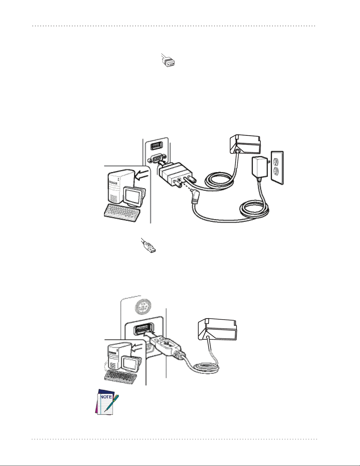
Setup
Installing the Interface Cable
RS-232 Serial Connection
Turn off power to the terminal/PC and connect the reader to the terminal/PC serial port via the
RS-232 cable, as shown in Figure 1. If the terminal will not support POT (Power Off the
Terminal) to supply reader power, use the approved power supply
Adapter barrel connector into the socket on the RS-232 cable connector and the AC Adapter
plug into a standard power outlet.
Figure 1. RS-232 Connection
(AC Adapter). Plug the AC
USB Connection
Connect the reader to a USB port on the terminal/PC using the USB cable for the interface type
you ordered. Reference Figure 2.
Figure 2. USB connection
Specific cables are required for connection to different hosts. The connectors illustrated above are examples only. A
those illustrated, but the steps to connect the reader remain the same.
ctual connectors may vary from
12
Gryphon™ I GFS4170/GFS4150-9
Page 15

Interface Selection
Upon completing the physical connection between the reader and its host, proceed to Table 1
starting on page 14 to select the interface type the reader is connected to (for example, RS-232
or USB). Scan the appropriate barcode in that section to conf
interface type.
Each reader model will support one of the following sets of host interfaces:
GFS4150-9 Model GFS4170 Model
• RS-232-STD
• RS-232 Wincor-Nixdorf
Setting the Interface
Scan the programming barcode from this section which selects the appropriate interface type
matching the system the reader will be connected to. Next, proceed to the corresponding
section in this manual (also listed in Table 1 starting on page 14) to configure any desired
settings and features associated with that interface.
Interface Selection
igure your system’s correct
• USB-COM, USB-KBD, USB_KBD-ALT,
KBD-Apple
USB-
Unlike some programming features and options, interface selections
require that you scan only one programming barcode label. DO NOT scan
an ENTER/EXIT barcode prior to scanning an interface selection barcode.
Some interfaces require the scanner to star
powered up. If additional scanner configuration is desired while in this
state, pull the trigger and hold it for five seconds. The scanner will
change to a state that allows programming with barcodes.
t in the disabled state when
Product Reference Guide
13
Page 16
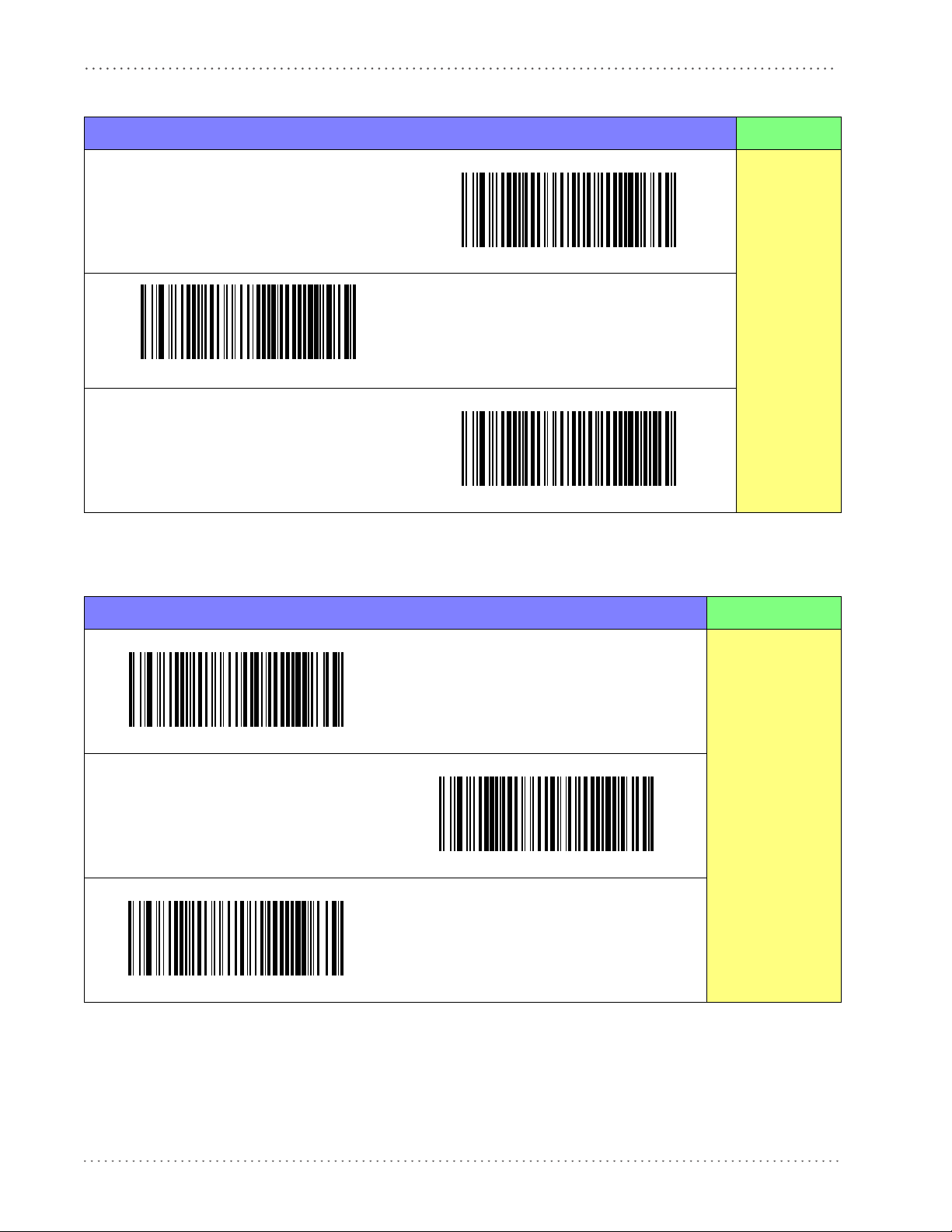
Setup
Table 1. Available Interfaces
RS-232 FEATURES
RS-232 standard interface
Select RS-232 STD
Set RS-232
Interface
Features
starting on
page 21
Select USB-COM-STD
RS-232 Wincor-Nixdorf
USB Com to simulate RS-232 standard interface
a
Select RS-232 Wincor-Nixdorf
a. Download the correct USB COM driver from the Datalogic Scanning website.
KEYBOARD FEATURES
USB Keyboard with standard key encoding
Select USB Keyboard
Set KEYBOARD
Interface
USB Keyboard with alternate key encoding
Features
starting on page
Select USB Alternate Keyboard
USB Keyboard for Apple computers
Select USB-KBD-APPLE
33
14
Gryphon™ I GFS4170/GFS4150-9
Page 17

Customizing Configuration Settings
Transmit Software Version
Configure Interface Settings
If after scanning the interface barcode from the previous table, your installation requires you to
select options to further customize your reader, turn to the appropriate section for your interface
type in "Configuration Using Barcodes" start
• "RS-232 ONLY Interface" on page 21
• "RS-232/USB-Com Interfaces" on page 26
• "USB Keyboard Interfaces" on page 33
Global Interface Features
See "Global Interface Features" on page 19 for settings configurable by all interface types.
Software Version Transmission
ing on page 17.
Customizing Configuration Settings
The software version of the device can be transmitted over the RS-232 and Keyboard interfaces
by scanning the following label.
Product Reference Guide
15
Page 18

Setup
Restore Custom Default Configuration
Resetting Product Configuration to Defaults
Restore Custom Defaults
If you aren’t sure what programming options are in your imager, or you’ve changed some
options and want to restore the Custom Default Configuration that may have been saved in the
scanner, scan the Restore Custom Default Configuration barcode below. This will restore the
custom configuration for the currently active interface.
Custom defaults are based on the interface type. Configure the imager
for the correct interface before scanning this label.
Restore Factory Configuration
If you want to restore the Factory Configuration for your imager, scan the Restore Factory
Configuration barcode below. The label restores the scanner configuration to the factory
settings, including the interface type. The Label ID set is shown in the “Label ID” section on
page 44 of this manual.
Restore Factory Configuration
The programming items listed in the following sections show the factory default settings for
each of the menu commands.
16
Gryphon™ I GFS4170/GFS4150-9
Page 19

Configuration Using Barcodes
This and following sections provide programming barcodes to configure your reader by
changing the default settings. For details about additional methods of programming, see
Configuration Methods on page 9.
You must first enable your reader to read barcodes in order to use this
section. If you have not done this, go to
complete the appropria
Configuration Parameters
Once the reader is set up, you can change the default parameters to meet your application needs.
Refer to "Standard Defaults" starting on page 263 for initial configuration in order to set the
default values and select the interface for your application.
te procedure.
Chapter 3
Setup, starting on page 11
and
The following configuration parameters are applicable to all
manual, unless otherwise indicated. The items are divided into logical groups, making it easy to
find the desired function based on its reference group.
Gryphon models covered in this
Interface Configuration:
• "RS-232 ONLY Interface" on page 21
• "RS-232/USB-Com Interfaces" on page 26
• "USB Keyboard Interfaces" on page 33
Parameters common to all interface applications:
• "Data Format" on page 41 gives options to control the messages sent to the Host system.
• "Reading Parameters" on page 65 control various operating modes and indicators status
functioning.
Symbology-specific parameters:
• "Code Selection" on page 77 provides configuration of a personalized mix of codes, code
families and their options.
Product Reference Guide
17
Page 20

Configuration Using Barcodes
Reading Configuration Barcodes
You must first enable your reader to read barcodes in order to use this
section. If you have not done this, go to
complete the appropria
To program features:
1. Scan the ENTER/EXIT PROGRAMMING barcode, available at the top of each programming page, when applicable.
2. Scan the barcode to set the desired programming feature. You may need to cover unused
es on the
barcod
barcode you intend to scan.
3. If additional input parameters are needed, go to Appendix D, Keypad, and scan the appropriate characters from the keypad.
page, and possibly the facing page, to ensure that the reader reads only the
Additional information about many features can be found in the “References” chapter.
te procedure.
Setup, starting on page 11
and
If you make a mistake before the last character, scan the CANCEL barcode to
t and not sa
abor
ning.
ve the entry string. You can then start again at the begin-
4. Complete the programming sequence by scanning the ENTER/EXIT PROGRAMMING barcode to exit Programming Mode.
For detailed descriptions, programming information and exam
ples for setting selected
configuration items, see References, starting on page 233.
18
Gryphon™ I GFS4170/GFS4150-9
Page 21
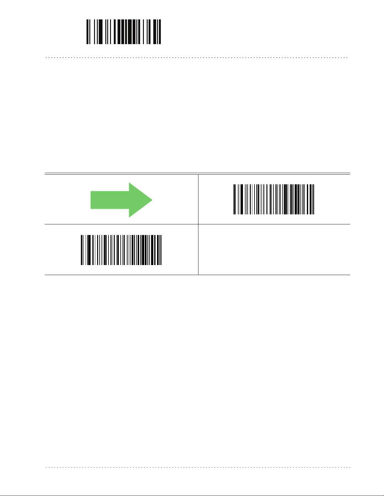
ENTER/EXIT PROGRAMMING MODE Host Commands — Obey/Ignore
DEFAULT
GLOBAL INTERFACE FEATURES
The following interface features are configurable by all interface types.
Host Commands — Obey/Ignore
This option specifies whether the reader will obey or ignore host commands. When set to
ignore, the reader will ignore all host commands except for those necessary for:
•service mode
• flash programming mode
• keeping the interface active
• transmission of labels
Host Commands = Obey
Host Commands = Ignore
Product Reference Guide
19
Page 22

Configuration Using Barcodes ENTER/EXIT PROGRAMMING MODE
NOTES
20
Gryphon™ I GFS4170/GFS4150-9
Page 23

RS-232 ONLY INTERFACE
BAUD RATE on page 22
DATA BITS on page 23
STOP BITS on page 23
PARITY on page 24
HANDSHAKING CONTROL on page 25
Use the programming barcodes in this section if modification
settings are necessary to meet your system’s requirements. Additional settings which apply to
both the RS-232 and USB interfaces are available in the next section, "RS-232/USB-Com
Interfaces" starting on page 4-26.
Reference Appendix B, Standard Defaults for a listing of standard factory settings.
s to the standard RS-232 interface
Product Reference Guide
21
Page 24
RS-232 ONLY Interface ENTER/EXIT PROGRAMMING MODE
DEFAULT
Baud Rate
See page 233 for information on this feature.
Baud Rate = 1200
Baud Rate = 2400
Baud Rate = 4800
Baud Rate = 9600
Baud Rate = 38,400
Baud Rate = 19,200
Baud Rate = 57,600
22
Baud Rate = 115,200
Gryphon™ I GFS4170/GFS4150-9
Page 25
ENTER/EXIT PROGRAMMING MODE Data Bits
Data Bits
This parameter allows the reader to interface with devices requiring a 7-bit or 8-bit ASCII
protocol for sending and receiving data.
7 Data Bits
DEFAULT
8 Data Bits
Stop Bits
Set the number of stop bits to match host device requirements. See page 233 for more
information on this feature.
DEFAULT
1 Stop Bit
2 Stop Bits
Product Reference Guide
23
Page 26
RS-232 ONLY Interface ENTER/EXIT PROGRAMMING MODE
Parity
This feature specifies parity required for sending and receiving data. Select the parity type
according to host device requirements. See page 233 for more information.
DEFAULT
Parity = None
Parity = Even
Parity = Odd
24
Gryphon™ I GFS4170/GFS4150-9
Page 27

ENTER/EXIT PROGRAMMING MODE Handshaking Control
Handshaking Control
See page 233 for more information about this feature.
DEFAULT
Handshaking Control = RTS
Handshaking Control = RTS/CTS
Handshaking Control = RTS/XON/XOFF
Handshaking Control = RTS On/CTS
Handshaking Control = RTS/CTS Scan Control
Product Reference Guide
25
Page 28

RS-232/USB-COM INTERFACES
INTERCHARACTER DELAY on page 27
BEEP ON ASCII BEL on page 27
BEEP ON NOT ON FILE on page 28
ACK NAK OPTIONS on page 28
ACK CHARACTER on page 29
NAK CHARACTER on page 29
ACK NAK TIMEOUT VALUE on page 30
ACK NAK RETRY COUNT on page 30
ACK NAK ERROR HANDLING on page 31
INDICATE TRANSMISSION FAILURE on page 31
DISABLE CHARACTER on page 32
ENABLE CHARACTER on page 32
The programming barcodes in this chapter allow modifications to the standard RS-232 and
USB-Com interfaces. Reference Ap
settings.
pendix B, Standard Defaults for a listing of standard factory
Product Reference Guide
26
Page 29
ENTER/EXIT PROGRAMMING MODE Intercharacter Delay
DEFAULT
00 = No Intercharacter Delay
Intercharacter Delay
This parameter specifies the intercharacter delay between the end of one character and the
beginning of the next. The delay can be set within a range of zero (0) to 990 milliseconds in
10ms increments. A setting of zero specifies no delay.
See page 234 for more information.
Select Intercharacter Delay Setting
Make a mistake? Scan the CANCEL barcode to abort and not
e the entry string. You can then start again.
sav
Intercharacter Delay = No Delay
To configure this feature, scan the ENTER/EXIT PROGRAMMING MODE barcode above, then the barcode at left followed
the digits (in hex) from the Alphanumeric characters in
by
Appendix D, Keypad
End by scanning the ENTER/EXIT bar
representing your desired character(s).
code again.
CANCEL
Beep On ASCII BEL
When this parameter is enabled, the reader issues a beep when a <BEL> character is detected on
the RS-232 serial line. <BEL> is issued to gain a user's attention to an illegal entry or other
important event.
DEFAULT
Beep On ASCII BEL = Disable
Beep On ASCII BEL = Enable
Product Reference Guide
27
Page 30
RS-232/USB-Com Interfaces ENTER/EXIT PROGRAMMING MODE
DEFAULT
Beep On Not on File
This option enables/disables the action of the reader to sound a three beep sequence upon
receiving a Not-On-File (NOF) host command.
Beep On Not On File = Disable
Beep On Not On File = Enable
ACK NAK Options
This enables/disables the ability of the reader to support the RS-232 ACK/NAK protocol.
See page 235 for more information.
DEFAULT
ACK/NAK Protocol = Enable for label transmission
ACK/NAK Protocol = Enable for label transmission and host-
command acknowledge
ACK/NAK Protocol = Disable ACK/NAK
ACK/NAK Protocol = Enable for host-command
acknowledge
28
Gryphon™ I GFS4170/GFS4150-9
Page 31

ENTER/EXIT PROGRAMMING MODE ACK Character
0x06 ‘ACK’ Character
0x15 ‘NAK’ Character
ACK Character
This setting specifies an ASCII character or hex value to be used as the ACK character. ASCII
characters or any hex value from 0 to 0xFF can be selected. See page 235 for more information.
Setting to previously defined characters such as XON, XOFF, or host commands conflicts with normal operation of these characters. 8-bit data is not
gnized when the option
reco
Select ACK Character Setting
Data Bits
has been set as 7 Data Bits.
DEFAULT
NAK Character
This setting specifies an ASCII character or hex value to be used as the NAK character. ASCII
characters or any hex value from 0 to 0xFF can be selected.
Setting to previously defined characters such as XON, XOFF, or host commands conflicts with normal operation of these characters
recognized when the option
Select NAK Character Setting
Data Bits
has been set as 7 Data Bits.
See page 236 for more information.
. 8-bit data is not
DEFAULT
The ACK/NACK Characters must be different and must not contain reserved
characters (see
Product Reference Guide
Appendix E, Reserved Characters
).
29
Page 32

RS-232/USB-Com Interfaces ENTER/EXIT PROGRAMMING MODE
DEFAULT
01 ACK NAK Timeout value is 200ms
003 = 3 Retries
ACK NAK Timeout Value
This option specifies the amount of time the reader waits for an ACK character from the host
following label transmission. The selectable timeout range is 200 milliseconds to 15,000ms (15
seconds) in 200ms increments. A selection of 0 disables the timeout.
See page 237 for more information on setting this feature.
To configure this feature, scan the ENTER/EXIT
RAMMING MODE barcode above, then the barcode at
PROG
left followed by the digits (in hex) from the Alphanumeric
Select ACK NAK Timeout Value Setting
Make a mistake? Scan the CANCEL barcode to abort and not
e the entry string. You can then start again at the begin-
sav
ning.
characters in
character(s). End by scanning the ENTE
Appendix D, Keypad
CANCEL
representing your desired
R/EXIT barcode again.
ACK NAK Retry Count
This feature specifies the number of times the reader retries a label transmission due to a retry
condition. The selectable range is from 1 to 254 retries. A selection of 0 disables the count, and
a selection of 255 specifies unlimited retries. See page 238 for more information.
Select ACK NAK Retry Count Setting
Make a mistake? Scan the CANCEL barcode to abort and not
e the entry string. You can then start again at the begin-
sav
ning.
DEFAULT
To configure this feature, scan the ENTER/EXIT PROGRAMMING MODE barcode above, then the barcode at left followed
the digits (in hex) from the Alphanumeric characters in
by
Appendix D, Keypad
End by scanning the ENTER/EXIT bar
representing your desired character(s).
code again.
CANCEL
30
Gryphon™ I GFS4170/GFS4150-9
Page 33

ENTER/EXIT PROGRAMMING MODE ACK NAK Error Handling
ACK NAK Error Handling
This feature specifies the method the reader uses to handle receive errors detected while waiting
for an ACK character from the host.
DEFAULT
ACK NAK Error Handling = Process Error as Valid ACK Character
ACK NAK Error Handling = Ignore Errors Detected
Indicate Transmission Failure
This option enables/disables the reader’s ability to sound an error beep to indicate a
transmission failure while in ACK/NAK mode
Indicate Transmission Failure = Enable Indication
ACK NAK Error Handling = Process Error as
Valid NAK Character
.
Indicate Transmission Failure = Disable Indication
DEFAULT
Product Reference Guide
31
Page 34

RS-232/USB-Com Interfaces ENTER/EXIT PROGRAMMING MODE
0x44 = Disable Character is ‘D’
0x45 = Enable Character is ‘E’
Disable Character
Specifies the value of the RS-232 host command used to disable the reader. ASCII characters or
any hex value from 0 to 0xFF can be selected.
Setting to previously defined characters such as XON, XOFF or host commands conflicts with normal operation of these charac
not recognized when
See page 239 for more information on setting this feature.
Select Disable Character Setting
Data Bits
are set as 7 Data Bits.
ters. 8-bit data is
DEFAULT
Enable Character
Specifies the value of the RS-232 host command used to enable the reader. ASCII characters or
any hex value from 0 to 0xFF can be selected.
Setting to previously defined characters such as XON, XOFF or host commands conflicts with normal operation of these characters. 8-bit data is
not reco
See page 240 in “References” for more information on setting this feature.
Select Enable Character Setting
gnized when
Data Bits
are set as 7 Data Bits.
DEFAULT
32
The Enable/Disable Characters must be different and must not contain
reserved characters (see
Appendix E, Reserved Characters
Gryphon™ I GFS4170/GFS4150-9
)
Page 35

USB KEYBOARD INTERFACES
COUNTRY MODE on page 34
SEND CONTROL CHARACTERS on page 37
USB KEYBOARD SPEED on page 38
Use the programming barcodes in this chapter to select options for USB Keyboard Interfaces.
R
eference Appendix B, Standard Defaults for a listing of standard factory settings.
Information about control character emulation which applies to keyboard
Appendix F, S ca nc od e Ta bl es .
interfaces is listed in
Product Reference Guide 33
Page 36

USB Keyboard Interfaces ENTER/EXIT PROGRAMMING MODE
Country Mode
This feature specifies the country/language supported by the keyboard.
Only the USB Keyboard (without alternate key encoding) interface supports ALL Country
Modes.
All other interfaces support ONLY the following Country Modes: U.S., B
France, Germany, Italy, Spain, Sweden.
DEFAULT
Country Mode = U.S.
Country Mode = Belgium
Country Mode = Britain
elgium, Britain,
Country Mode = Croatia
Supports only the interfaces listed in the Country Mode feature
desc
ription.
34
Supports only the interfaces listed in the Country Mode feature description.
Country Mode = Czechoslovakia
Gryphon™ I GFS4170/GFS4150-9
Page 37

ENTER/EXIT PROGRAMMING MODE Country Mode
Country Mode — continued
Country Mode = Denmark
Country Mode = Germany
Supports only the interfaces listed in the Country Mode feature
desc
ription.
Supports only the interfaces listed in the Co
ture description.
Country Mode = France
Country Mode = Hungary
untry Mode fea-
Country Mode = Italy
Supports only the interfaces listed in the Country Mode feature
desc
ription.
Country Mode = Japanese 106-key
Supports only the interfaces listed in the Co
ture description.
Country Mode = Norway
untry Mode fea-
Product Reference Guide 35
Page 38

USB Keyboard Interfaces ENTER/EXIT PROGRAMMING MODE
Country Mode — continued
Supports only the interfaces listed in the Country Mode feature description.
Country Mode = Poland
Supports only the interfaces listed in the Country Mode feature
desc
ription.
Country Mode = Portugal
Supports only the interfaces listed in the Country Mode feature description.
Country Mode = Romania
Supports only the interfaces listed in the Country Mode feature
desc
ription.
Country Mode = Spain
Country Mode = Switzerland
Country Mode = Slovakia
Country Mode = Sweden
Supports only the interfaces listed in the Country Mode feature description.
36
Gryphon™ I GFS4170/GFS4150-9
Page 39

ENTER/EXIT PROGRAMMING MODE Send Control Characters
Send Control Characters
This feature Specifies how the reader transmits ASCII control characters to the host. Reference
Appendix F, S ca nc od e Ta bl es for more information about control characters.
Options are as follows:
Control Character 00 .
special keys are located from 0x80 to 0xA1.
Control Character 01 .
Key, special keys are located from 0x80 to 0xA1.
Control Character 02 .
0xFE are intended as an extended ASCII table (Microsoft Windows Codepage 1252 — see
"Microsoft Windows Codepage 1252"on page 288).
Characters from 00 to 0x1F are sent as control character Ctrl+Keys,
Characters from 00 to 0x1F are sent as control character Ctrl+Capital
Special keys are located from 00 to 0x1F and characters from 0x80 to
DEFAULT
Send Control Characters = 00
Send Control Characters = 01
Send Control Characters = 02
Product Reference Guide 37
Page 40

USB Keyboard Interfaces ENTER/EXIT PROGRAMMING MODE
USB Keyboard Speed
This option specifies the USB poll rate for a USB keyboard.
DEFAULT
USB Keyboard Speed = 1ms
USB Keyboard Speed = 2ms
USB Keyboard Speed = 4ms
USB Keyboard Speed = 3ms
USB Keyboard Speed = 5ms
38
Gryphon™ I GFS4170/GFS4150-9
Page 41

ENTER/EXIT PROGRAMMING MODE USB Keyboard Speed
USB Keyboard Speed — continued
USB Keyboard Speed = 6ms
USB Keyboard Speed = 7ms
USB Keyboard Speed = 8ms
USB Keyboard Speed = 10ms
USB Keyboard Speed = 9ms
Product Reference Guide 39
Page 42

USB Keyboard Interfaces ENTER/EXIT PROGRAMMING MODE
NOTES
40
Gryphon™ I GFS4170/GFS4150-9
Page 43

DATA FORMAT
GLOBAL PREFIX/SUFFIX on page 42
GLOBAL AIM ID on page 43
GS1-128 AIM ID
on page 44
LABEL ID starting on page 44
•
Label ID: Pre-loaded Sets
•
Label ID: Set Individually Per Symbology
•
Label ID Control
•
Label ID Symbology Selection
SET GLOBAL MID LABEL ID CHARAC-
TERS on page 50
NO READ STRING on page 51
CODE VERIFIER starting on page 52
•
Code Verifier Mode
•
Match String
•
Wrong Code String
The features in this chapter can be used to build specific user-defined data
string. See “References” starting on page 241 for more detailed instructions on setting these
features.
Product Reference Guide
CASE CONVERSION on page 54
CHARACTER CONVERSION on page 55
into a message
41
Page 44

Data Format ENTER/EXIT PROGRAMMING MODE
No Global Prefix
Global Suffix = 0x0D (CR)
Global Prefix/Suffix
This option sets up to 20 characters each from the set of ASCII characters or any hex value from
00 to FF. The characters may be added as a prefix (in a position before the barcode data, also
called a header) and/or as a suffix (in a position following the barcode data, also called a footer).
See page 242 for more detailed instructions on setting this feature.
To configure this feature, scan the ENTER/EXIT PROGRAMMING MODE barcode above
to place the unit in Pr
barcode followed by the digits (in hex) from the Alphanumeric characters in Appendix D, Keypad
representing your desired character(s). If less than the expe
selected, scan the ENTER/EXIT barcode to terminate the string. Exit programming mode by
scanning the ENTER/EXIT barcode again.
ogramming Mode, then the “Set Global Prefix” or “Set Global Suffix,”
cted string of 20 characters are
Set Global Prefix
Set Global Suffix
Make a mistake? Scan the CANCEL barcode to abort and not
ve the entry string. You can then start again at the beginning.
sa
DEFAULT
CANCEL
42
Gryphon™ I GFS4170/GFS4150-9
Page 45

ENTER/EXIT PROGRAMMING MODE Global AIM ID
Global AIM ID
This feature enables/disables addition of AIM IDs for all symbology
types.
AIM label identifiers (as opposed to custom characters you select yourself as with label
identifiers) can be included with scanned barcode data. AIM label identifiers consist of three
characters as follows:
• A close brace character (ASCII ‘]’), followed by...
• A code character (see the table below), followed by...
• A modifier character (the modifier character is symbol dependent).
SYMBOLOGY CHAR SYMBOLOGY CHAR
UPC/EAN
Code 39 and
Code 32
Co
dabar F Standard 2 of 5 S
Interleaved 2 of 5 I ISBN
Code 93 G Code 11 H
a. UPC-A and UPC-E labels are converted to EAN 13 when adding AIM IDs.
b. ISBN (X with a 0 modifier character)
a
E
A
Code 128/GS1-128 C
DataBar Omnidirectional,
taBar Expanded
Da
DEFAULT
Global AIM ID = Disable
e
b
X
Global AIM ID = Enable
Product Reference Guide
43
Page 46

Data Format ENTER/EXIT PROGRAMMING MODE
DEFAULT
GS1-128 AIM ID
If Global AIM ID is disabled, the AIM ID for GS1-128 can be enabled/disabled independently.
The AIM ID for GS1-128 is a ]C1, ]C2 or ]C3.
AIM IDs for other symbologies can be enabled/disabled independently as well
Customer Support for assistance
GS1-128 AIM ID = Disable
GS1-128 AIM ID = Enable
. Contact
Label ID
A Label ID is a customizable code of up to three ASCII characters (each can be one of hex 0x010xFF), used to identify a barcode (symbology) type. It can be appended previous to or following
the transmitted barcode data depending upon how this option is enabled. This feature provides
options for configuring custom Label IDs as a pre-loaded set (see "Label ID: Pre-loaded Sets"
below) or individually per symbology (see "Label ID: Set Individually Per Symbology"on
page 45). If you wish to program the reader to always
identifier for ALL symbology types, see the previous feature "Global AIM ID"on page 43.
include an industry standard label
44
See Label ID, starting on page 244 of “References” for more information on setting this feature.
Label ID: Pre-loaded Sets
The reader supports two pre-loaded sets of Label IDs. See Label ID: Pre-loaded Sets, starting on
page 244 for details on the USA set and the EU set.
When changing from one Label ID set to another, all other reader configu-
ace type, will be erased and set to
Gryphon™ I GFS4170/GFS4150-9
CAUTION
ration settings, including the host interf
the standard factory defaults. Any custom configuration or custom defaults
will be lost.
Page 47

ENTER/EXIT PROGRAMMING MODE Label ID: Set Individually Per Symbology
DEFAULT
Label ID Pre-loaded Set = USA Set
Label ID Pre-loaded Set = EU Set
Label ID: Set Individually Per Symbology
This feature configures a Label ID individually for a single symbology. See Label ID: Set
Individually Per Symbology, starting on page 246 for detailed instructions on se
tting this feature.
Label ID Control
This option controls whether a Label ID is disabled, or sent as a prefix or suffix for a given
symbology type.
DEFAULT
Label ID Transmission = Enable as Prefix
Label ID Transmission = Disable
Label ID Transmission = Enable as Suffix
Product Reference Guide
45
Page 48

Data Format ENTER/EXIT PROGRAMMING MODE
Label ID Symbology Selection
This option selects the symbology for which a Label ID is to be configured. See "Label ID"on
page 44 or page 246 in “References” for more
Set UPC-A/P2 Label ID Character(s)
detailed instructions.
Set UPC-A Label ID Character(s)
Set UPC-E Label ID Character(s)
Set UPC-E/P5 Label ID Character(s)
Set UPC-A/P5 Label ID Character(s)
Set UPC-E/P2 Label ID Character(s)
46
Set EAN 13 Label ID Character(s)
Gryphon™ I GFS4170/GFS4150-9
Page 49

ENTER/EXIT PROGRAMMING MODE Label ID Symbology Selection
Label ID Symbology Selection — continued
Set EAN 13/P2 Label ID Character(s)
Set EAN 13/P5 Label ID Character(s)
Set EAN 8 Label ID Character(s)
Set EAN 8/P5 Label ID Character(s)
Set GTIN/P2 Label ID Character(s)
Set EAN 8/P2 Label ID Character(s)
Set GTIN Label ID Character(s)
Set GTIN/P5 Label ID Character(s)
Product Reference Guide
47
Page 50

Data Format ENTER/EXIT PROGRAMMING MODE
Label ID Symbology Selection — continued
Set Code 39 Label ID Character(s)
Set Code 32 Label ID Character(s)
Set Code 39 CIP Label ID Character(s)
Set Code 128 Label ID Character(s)
Set ISBT 128 Label ID Character(s)
Set Standard 2 of 5 Label ID Character(s)
Set GS1-128 Label ID Character(s)
Set Interleaved 2 of 5 Label ID Character(s)
48
Gryphon™ I GFS4170/GFS4150-9
Page 51

ENTER/EXIT PROGRAMMING MODE Label ID Symbology Selection
Label ID Symbology Selection — continued
Set Industrial 2 of 5 Label ID Character(s)
Set IATA Label ID Character(s)
Set Datalogic 2 of 5 Label ID Character(s)
Set ABC Codabar Label ID Character(s)
Set DataBar Expanded Label ID Character(s)
Set Codabar Label ID Character(s)
Set DataBar Omnidirectional Label ID Character(s)
Product Reference Guide
49
Page 52

Data Format ENTER/EXIT PROGRAMMING MODE
DEFAULT
No Mid Label ID
Character (00)
Label ID Symbology Selection — continued
Set DataBar Limited Label ID Character(s)
Set Code 93 Label ID Character(s)
Set MSI Label ID Character(s)
Set Plessey Label ID Character(s)
Set Global Mid Label ID Characters
Specifies mid-label ID that is added for transmission between the labels of a two-label pair.
Set Global Mid Label ID Character(s)
Make a mistake? Scan the CANCEL barcode to abort and not
sa
ve the entry string. You can then start again at the beginning.
To configure this feature, scan the ENTER/EXIT PROGRAMMING
MODE barcode above, then the barcode at left followed by the
digits (in hex) from the Alphanumeric characters in
D, Keypad
representing your desired character(s). End by scan-
Appendix
ning the ENTER/EXIT barcode again.
CANCEL
50
Gryphon™ I GFS4170/GFS4150-9
Page 53

ENTER/EXIT PROGRAMMING MODE No Read String
DEFAULT
0x18 = (CAN)
No Read String
This feature defines the string or character to be displayed in case of No Read during a reading
phase (in On Line Mode only). It allows up to 20 characters, from the set of ASCII characters or
any hex value from 00 to FE.
Select No Read String
Make a mistake? Scan the CANCEL barcode to abort and not
a
ve the entry string. You can then start again at the beginning.
s
See No Read String on page 248 for more information on setting this feature.
To configure this feature, scan th
e ENTER/EXIT PROGRAMMING
MODE barcode above, then the barcode at left followed by the
digits (in hex) from the Alphanumeric characters in
D, Keypad
representing your desired character(s). If less than
Appendix
the expected string of 20 characters are selected, scan the
ENTER/EXIT b
arcode to terminate the string.End by scanning
the ENTER/EXIT barcode again.
CANCEL
Product Reference Guide
51
Page 54

Data Format ENTER/EXIT PROGRAMMING MODE
DEFAULT
CODE VERIFIER
This feature allows the scanner to verify that all codes read and decoded match a defined string
saved in its memory. It is valid when in On Line, Serial On Line, Automatic and Automatic
(Object Sense) Operating Modes.
If the code read matches the code verifier Match String, then it is sent to the host through the
configured port. If it does not match th
send either the Wrong Code or a defined Wrong String message to indicate the error.
See page 249 in “References” for more information about these features.
Code Verifier Mode
Disable or specify parameters for Code Verifier Mode. See page 249 in “References” for more
information.
e code verifier Match String, you can specify whether to
Disabled
Transmit Wrong Code
Transmit Wrong String
52
Gryphon™ I GFS4170/GFS4150-9
Page 55

ENTER/EXIT PROGRAMMING MODE Match String
Match String
This feature allows you to define the string to be used as the match code for Code Verification.
The Match String must be configured to include start/stop characters and check digits if their
transmission is enabled. See page 249 in “References” for more information.
It is possible to define the Match string by inserting:
all printable characters
•
• non printable ASCII characters
No wild card characters are supported.
Set Match String
Make a mistake? Scan the CANCEL barcode to abort and not
ve the entry string. You can then start again at the beginning.
sa
To configure this feature, scan th
MODE barcode above, then the barcode at left followed by the
digits (in hex) from the Alphanumeric characters in
D, Keypad
ning the ENTER/EXIT barcode again.
representing your desired character(s). End by scan-
e ENTER/EXIT PROGRAMMING
Appendix
CANCEL
Product Reference Guide
53
Page 56

Data Format ENTER/EXIT PROGRAMMING MODE
Wrong Code String
See page 250 in “References” for more information about this feature.
Set Wrong Code String
Make a mistake? Scan the CANCEL barcode to abort and not
ve the entry string. You can then start again at the beginning.
sa
Case Conversion
This feature allows conversion of the case of all alphabetic characters to upper or lower case.
Case conversion affects ONLY scanned barcode data, and does not affect Label
ID, Prefix, Suffix, or other appended data.
To configure this feature, scan th
e ENTER/EXIT PROGRAMMING
MODE barcode above, then the barcode at left followed by the
digits (in hex) from the Alphanumeric characters in
D, Keypad
representing your desired character(s). End by scan-
Appendix
ning the ENTER/EXIT barcode again.
CANCEL
DEFAULT
Case Conversion = Disable (no case conversion)
Case Conversion = Convert to upper case
Case Conversion = Convert to lower case
54
Gryphon™ I GFS4170/GFS4150-9
Page 57

ENTER/EXIT PROGRAMMING MODE Character Conversion
0xFFFFFFFFFFFFFFFF
(No character conversion)
Character Conversion
Character conversion is an eight byte configuration item. The eight bytes are 4 character pairs
represented in hexadecimal ASCII values. The first character in the pair is the character that will
be converted. The second character in the pair is the character to convert to. If the character to
convert in a pair is FF, then no conversion is done.
If less than the expected string of 16 characters are selected, scan the ENTER/
EXIT barcode twice to accept the selections and exit Programming Mode.
Configure Character Conversion
Make a mistake? Scan the CANCEL barcode to abort and not
ve the entry string. You can then start again at the beginning.
sa
To configure this feature, scan the ENTER/EXIT PROGRAMMING
MODE barcode above, then the barcode at left, followed by the
digits (in hex) from the Alphanumeric characters in
D, Keypad
ning the ENTER/EXIT barcode again.
representing your desired character(s). End by scan-
CANCEL
Appendix
DEFAULT
Product Reference Guide
55
Page 58

Data Format ENTER/EXIT PROGRAMMING MODE
NOTES
56
Gryphon™ I GFS4170/GFS4150-9
Page 59

DIGITAL OUTPUT
ACTIVATION EVENT on page 58
DEACTIVATION EVENT on page 59
DEACTIVATION TIMEOUT on page 59
ACTIVATION STATE on page 60
See page 255 in “References” for more information about Digital Output.
Use the programming barcodes in this chapter to select opt
Appendix B, Standard Defaults for a listing of standard factory settings.
ions for
Digital Outputs. Reference
Product Reference Guide 57
Page 60

Digital Output ENTER/EXIT PROGRAMMING MODE
DEFAULT
Activation Event
Defines the event activating the output.
Disable
Good Read
No Read
Wrong Code
58
Gryphon™ I GFS4170/GFS4150-9
Page 61

ENTER/EXIT PROGRAMMING MODE Deactivation Event
DEFAULT
005 = 500 msec.
Deactivation Event
Defines the event deactivating the output. See page 255 in “References” for more information
about this feature.
Disable
Timeout
Reading Phase Active
Deactivation Timeout
When Timeout is the selected Deactivation Event, this specifies the maximum duration of the
output pulse.
Set Deactivation Timeout
Make a mistake? Scan the CANCEL barcode to abort and not
ve the entry string. You can then start again at the beginning.
sa
To configure this feature, scan the ENTER/EXIT PROGRAMMING
MODE barcode above, then the barcode at left followed by the
digits (in hex) from the Alphanumeric characters in
D, Keypad
gramming mode by scanning the ENTER/EXIT barcode again.
representing your desired character(s). Exit pro-
CANCEL
Appendix
Product Reference Guide 59
DEFAULT
Page 62

Digital Output ENTER/EXIT PROGRAMMING MODE
DEFAULT
Activation State
Determines the active state of the output.
Closed
Open
60
Gryphon™ I GFS4170/GFS4150-9
Page 63

POWER SAVE
USB SUSPEND MODE on page 62
SLEEP MODE TIMEOUT on page 63
Use the programming barcodes in this chapter to s
B, Standard Defaults for a listing of standard factory settings.
elect Power Save options. Reference Appendix
Product Reference Guide 61
Page 64

Power Save ENTER/EXIT PROGRAMMING MODE
DEFAULT
USB Suspend Mode
This setting enables/disables the ability of USB interfaces to enter suspend mode. See page 254
in “References” for more information about this feature.
.
All LED indicators are off during USB Suspend.
USB Suspend Mode = Enable
USB Suspend Mode = Disable
62
Gryphon™ I GFS4170/GFS4150-9
Page 65

ENTER/EXIT PROGRAMMING MODE Sleep Mode Timeout
Sleep Mode Timeout
This feature sets the amount of time that the reader will be idle before it enters into a low power
Sleep Mode. When in Sleep Mode the reader can no longer receive commands from the Host or
base station until it is woken up again, either by a trigger pull or when an external trigger event
occurs.
See page 254 in “References” for more information about this feature.
This feature is available only for the GFS4150-9 (RS-232 interface) in On Line
operating mode.
DEFAULT
Sleep Mode Timeout = Disable
Sleep Mode Timeout = 30 Seconds
Sleep Mode Timeout = 5 minutes
Sleep Mode Timeout = 10 Seconds
Sleep Mode Timeout = 1 minute
Sleep Mode Timeout = 10 minutes
Product Reference Guide 63
Page 66

Power Save ENTER/EXIT PROGRAMMING MODE
NOTES
64
Gryphon™ I GFS4170/GFS4150-9
Page 67

READING PARAMETERS
ILLUMINATION MODE on page 66
LED AND BEEPER INDICATORS on page 66
• Power On Alert
• Good Read: When to Indicate
• Good Read Beep
• Good Read Beep Length
• Good Read LED Duration
• Green Spot Duration
• LED Indication
SCANNING FEATURES on page 71
• Operating Mode
• Phase Off Event
• Phase Off Timeout
• Serial Start Character
• Serial Stop Character
• Automatic Threshold
• Test Mode Multiple
Product Reference Guide
CAMERA CONTROL on page 75
• Exposure Mode
65
Page 68

Reading Parameters ENTER/EXIT PROGRAMMING MODE
Illumination Mode
Selects the illumination mode for the reader. Options are:
• Disabled: the illuminator is always off
• Enabled: the illuminator is always on
• Triggered: the illuminator is turned on when the reading phase starts, and turned off as
soon as the code(s) are r
ead or when the reading phase ends.
Illumination Mode = Disabled
Illumination Mode = Triggered
LED AND BEEPER INDICATORS
Illumination Mode = Enabled
DEFAULT
Power On Alert
Disables or enables the indication (from the Beeper) that the reader is receiving power.
Power On Alert = Disable (No Audible Indication)
DEFAULT
Power On Alert = Enable
66
Gryphon™ I GFS4170/GFS4150-9
Page 69

ENTER/EXIT PROGRAMMING MODE Good Read: When to Indicate
DEFAULT
DEFAULT
Good Read: When to Indicate
This feature specifies when the reader will provide indication (beep and/or flash its green LED)
upon successfully reading a barcode.
This option, which uses CTS, is only valid for RS-232 interfaces.
Indicate Good Read = On Decode
Indicate Good Read = After Transmit
Good Read Beep
Enable/Disable the good read beep following a good read of a label
Enable Good Read Beep
Disable Good Read Beep
Product Reference Guide
67
Page 70

Reading Parameters ENTER/EXIT PROGRAMMING MODE
DEFAULT
Good Read Beep Length
Good Read Beep Length = 60 msec
Good Read Beep Length = 80 msec
Good Read Beep Length = 100 msec
Good Read Beep Length = 120 msec
Good Read Beep Length = 160 msec
Good Read Beep Length = 140 msec
Good Read Beep Length = 180 msec
68
Good Read Beep Length = 200 msec
Gryphon™ I GFS4170/GFS4150-9
Page 71

ENTER/EXIT PROGRAMMING MODE Good Read LED Duration
001 = Good Read LED
stays on for 100 ms.
Good Read LED Duration
This feature specifies the amount of time that the Good Read LED remains on following a good
read. The good read LED on time can be set within a range of 100 milliseconds to 25,500
milliseconds (0.1 to 25.5 seconds) in 100ms increments.
See page 251 in “References” for detailed instructions an
Select Good Read LED Duration Setting
Make a mistake? Scan the CANCEL barcode to abort and not
e the entry string. You can then start again at the begin-
sav
ning.
DEFAULT
d examples for setting this feature.
To configure this feature scan the ENTER/EXIT PROGRAMMING
MODE barc
the digits (in hex) from the Alphanumeric characters in
Appendix D, Keypad
End by scanning the ENTER/EXIT bar
ode above, then the barcode at left, followed by
representing your desired character(s).
code again.
CANCEL
All LED indicators are off during sleep.
Product Reference Guide
69
Page 72

Reading Parameters ENTER/EXIT PROGRAMMING MODE
Green Spot Duration
Specifies the duration of the good read pointer beam after a good read.
Green Spot Duration = Disable (Green Spot is Off)
DEFAULT
Green Spot Duration = Short (300 msec)
Green Spot Duration = Medium (500 msec)
Green Spot Duration = Long (800 msec)
LED Indication
Specifies when the scanner’s LEDs will provide notification of successful reading of a barcode.
Selections:
• On Decode = Indicate Good Read immediately after decoding.
• After Transmission = Indicate Good Read after code transmission to host.
LED Indication = On Decode
DEFAULT
LED Indication = After Transmission
70
Gryphon™ I GFS4170/GFS4150-9
Page 73

ENTER/EXIT PROGRAMMING MODE Operating Mode
SCANNING FEATURES
Operating Mode
Selects the reader's scan operating mode. See page 252 in “References” for more information.
DEFAULT
On Line
Serial On Line
Automatic
Test Mode
Automatic (Object Sense)
The barcode must remain steady before the reader in order for the
Test mode to work properly.
Product Reference Guide
71
Page 74

Reading Parameters ENTER/EXIT PROGRAMMING MODE
100 = Timeout set on for 2 seconds
Phase Off Event
Trigger Stop
Trigger Stop - Timeout
Phase Off Timeout
DEFAULT
Timeout
Timeout can be set within a range of 40 milliseconds to 5100 milliseconds (0.04 to 5.1 seconds)
in 20 ms increments.
Select Phase Off Timeout
Make a mistake? Scan the CANCEL barcode to abort and not
e the entry string. You can then start again at the begin-
sav
ning.
DEFAULT
To configure this feature scan the ENTER/EXIT PROGRAMMING
MODE barcode above, then the barcode at left, followed by
the digits (in hex) from the Alphanumeric characters in
Appendix D, Keypad
End by scanning the ENTER/EXIT bar
representing your desired character(s).
code again.
CANCEL
72
Gryphon™ I GFS4170/GFS4150-9
Page 75

ENTER/EXIT PROGRAMMING MODE Serial Start Character
DEFAULT
0x02 = Serial Start Character is [02 STX]
DEFAULT
0x03 = Serial Stop Character is [03 ETX]
Serial Start Character
See page 253 in “References” for more information.
Select Serial Start Characters
Make a mistake? Scan the CANCEL barcode to abort and not
e the entry string. You can then start again at the begin-
sav
ning.
Serial Stop Character
To configure this feature scan the ENTER/EXIT PROGRAMMING
MODE barc
ode above, then the barcode at left, followed by
the digits (in hex) from the Alphanumeric characters in
Appendix D, Keypad
End by scanning the ENTER/EXIT bar
representing your desired character(s).
code again.
CANCEL
See page 253 in “References” for more information.
Select Serial Stop Characters
Make a mistake? Scan the CANCEL barcode to abort and not
e the entry string. You can then start again at the begin-
sav
ning.
The Serial Start/Stop Characters must be different and must not contain
reserved characters (see
To configure this feature scan the ENTER/EXIT PROGRAMMING
MODE barcode above, then the barcode at left, followed by
the digits (in hex) from the Alphanumeric characters in
Appendix D, Keypad
End by scanning the ENTER/EXIT bar
representing your desired character(s).
code again.
CANCEL
Appendix E, Reserved Characters
)
Product Reference Guide
73
Page 76

Reading Parameters ENTER/EXIT PROGRAMMING MODE
DEFAULT
0x0A = 10
DEFAULT
Automatic Threshold
See page 253 in “References” for more information.
To configure this feature scan the ENTER/EXIT PROGRAMMING
ove, then the barcode at left, followed by
representing your desired character(s).
code again.
CANCEL
Select Automatic Threshold
Make a mistake? Scan the CANCEL barcode to abort and not
e the entry string. You can then start again at the begin-
sav
ning.
MODE barcode ab
the digits (in hex) from the Alphanumeric characters in
Appendix D, Keypad
End by scanning the ENTER/EXIT bar
Test Mode Multiple
This parameter is active only in Test Mode.
Disable:
Enable:
Enable Test Mode Multiple
Test mode is possible only for a single barcode
Test mode is possible for one or more barcodes at the mean time.
Disable Test Mode Multiple
74
Gryphon™ I GFS4170/GFS4150-9
Page 77

CAMERA CONTROL
Exposure Mode
Exposure Mode
Strobed Exposure Mode:
can be improved by flashing the scanner's lighting (strobe mode). The scanner strobes at a very
high frequency, so the change in lighting may not be apparent. When enabled, the scanner can
read codes moving at up to 1m/sec, depending on the bar size and direction the code is moving.
For any selectable scanning mode, performance on moving barcodes
DEFAULT
Continuous
Strobed
Product Reference Guide
75
Page 78

Reading Parameters
NOTES
76
Gryphon™ I GFS4170/GFS4150-9
Page 79

CODE SELECTION
The reader supports the following symbologies (barcode types). Symbology-dependent options
for each symbology are included in this chapter.
DISABLE ALL SYMBOLOGIES on page 78
CODE EAN/UPC on page 79
• Coupon Control
• UPC-A
• UPC-E • Code IATA
• EAN 13 (Jan 13)
• ISSN
• EAN 8 (Jan 8) • ABC Codabar
• UPC/EAN Global Settings
CODE 39 on page 106
• Code 32 (ITAL Pharmaceutical Code) • GS1 DataBar™ Expanded
• Code 39 CIP (French Pharmaceutical) • GS1 DataBar™ Limited
INTERLEAVED 2 OF 5 (I 2 OF 5) on page
134
STANDARD 2 OF 5 on page 142
INDUSTRIAL 2 OF 5 on page 148
DATALOGIC 2 OF 5 on page 155
CODABAR on page 161
GS1 DATABAR™ OMNIDIRECTIONAL
on page 175
• GS1 DataBar™ Omnidirectional
CODE 128 on page 121 CODE 93 on page 183
• GS1-128
MSI
on page 191
CODE ISBT 128 on page 132 PLESSEY on page 198
Default settings are indicated for each feature/option with a green arrow. Also
Appendix B, Standard Defaults for a listing of the most widely used set of standard factory
settings. That section also provides sp
for your system.
To set most features:
1. Scan the ENTER/EXIT PROGRAMMING barcode at the top of a
2. Scan the correct barcode to set the desired programming feature or parameter. You may
Product Reference Guide
ace to record any custom settings needed or implemented
ming pages.
need to cov
the reader reads only the barcode you intend to scan.
er unused barcodes on the page, and possibly the facing page, to ensure that
reference
pplicable pr
ogram-
77
Page 80

Disable All Symbologies
3. If additional input parameters are needed, go to Appendix D, Keypad, and scan the appro-
4. Complete the programming sequence by scanning the ENTER/EXIT PROGRAM-
Use this feature to disable all symbologies.
1. Scan the ENTER/EXIT PROGRAMMING barcode below.
priate characters from the keypad.
Additional information about many features can be found in the “References” chapter.
If you make a mistake before the last character, scan the CANCEL barcode to
t and not sa
abor
ning.
ve the entry string. You can then start again at the begin-
MING barcode to exit Programming Mode.
DISABLE ALL SYMBOLOGIES
2. Scan the Disable All Symbologies barcode.
3. Complete the programming sequence b
y
MING barcode.
ENTER/EXIT PROGRAMMING MODE
Disable All Symbologies
This does not disable the reading of programming labels.
scanning the ENTER/EXIT PROGRAM-
78
Gryphon™ I GFS4170/GFS4150-9
Page 81

ENTER/EXIT PROGRAMMING MODE Coupon Control
DEFAULT
CODE EAN/UPC
Coupon Control
This feature is used to control the reader’s method of processing coupon labels.
Coupon Control = Allow all coupon barcodes to be decoded
Coupon Control = Enable only UPCA coupon decoding
Coupon Control = Enable only GS1 DataBar™
coupon decoding
Product Reference Guide
79
Page 82

Code EAN/UPC ENTER/EXIT PROGRAMMING MODE
DEFAULT
DEFAULT
UPC-A
The following options apply to the UPC-A symbology.
UPC-A Enable/Disable
When disabled, the reader will not read UPC-A barcodes.
UPC-A = Disable
UPC-A = Enable
UPC-A Check Character Transmission
Enable this option to transmit the check character along with UPC-A barcode data.
UPC-A Check Character Transmission = Send
UPC-A Check Character Transmission = Don’t Send
80
Gryphon™ I GFS4170/GFS4150-9
Page 83

ENTER/EXIT PROGRAMMING MODE Expand UPC-A to EAN-13
DEFAULT
Expand UPC-A to EAN-13
Expands UPC-A data to the EAN-13 data format. Selecting this feature also changes the
symbology ID to match those required for EAN-13.
DEFAULT
UPC-A to EAN-13 = Don’t Expand
UPC-A to EAN-13 = Expand
UPC-A Number System Character Transmission
This feature enables/disables transmission of the UPC-A number system character.
UPC-A Number System Character = Transmit
UPC-A Number System Character = Do not transmit
Product Reference Guide
81
Page 84

Code EAN/UPC ENTER/EXIT PROGRAMMING MODE
UPC-A Minimum Reads
This feature specifies the minimum number of consecutive times a UPC-A label must be
decoded before it is accepted as a good read.
DEFAULT
UPC-A Minimum Reads = 1
UPC-A Minimum Reads = 2
UPC-A Minimum Reads = 4
UPC-A Minimum Reads = 3
82
Gryphon™ I GFS4170/GFS4150-9
Page 85

ENTER/EXIT PROGRAMMING MODE UPC-E Enable/Disable
DEFAULT
DEFAULT
UPC-E
The following options apply to the UPC-E symbology.
UPC-E Enable/Disable
When disabled, the reader will not read UPC-E barcodes.
UPC-E = Disable
UPC-E = Enable
UPC-E Check Character Transmission
Enable this option to transmit the check character along with UPC-E barcode data.
UPC-E Check Character Transmission = Send
UPC-E Check Character Transmission = Don’t Send
Product Reference Guide
83
Page 86

UPC-E ENTER/EXIT PROGRAMMING MODE
Expand UPC-E to EAN-13
Expands UPC-E data to the EAN-13 data format. Selecting this feature also changes the
symbology ID to match those required for EAN-13.
DEFAULT
UPC-E to EAN-13 = Don’t Expand
UPC-E to EAN-13 = Expand
Expand UPC-E to UPC-A
Expands UPC-E data to the UPC-A data format.
DEFAULT
UPC-E to UPC-A = Expand
UPC-E to UPC-A = Don’t Expand
84
Gryphon™ I GFS4170/GFS4150-9
Page 87

ENTER/EXIT PROGRAMMING MODE UPC-E Number System Character Transmission
DEFAULT
DEFAULT
UPC-E Number System Character Transmission
This feature enables/disables transmission of the UPC-E system number character.
UPC-E Number System Character = Do not transmit
UPC-E Number System Character = Transmit
UPC-E Minimum Reads
Specifies the minimum number of consecutive times a UPC-E label must be decoded before it is
accepted as a good read.
UPC-E Minimum Reads = 2
UPC-E Minimum Reads = 4
UPC-E Minimum Reads = 1
UPC-E Minimum Reads = 3
Product Reference Guide
85
Page 88

GTIN Formatting ENTER/EXIT PROGRAMMING MODE
GTIN FORMATTING
This feature enables/disables the ability to convert UPC-E, UPC-A, EAN 8, and EAN 13 labels
into the GTIN 14-character format.
If add-on information is present on the base label prior to the conversion taking place, the add-on information will be appended to
nverted GTIN label.
the co
DEFAULT
GTIN Formatting = Disable
GTIN Formatting = Enable
86
Gryphon™ I GFS4170/GFS4150-9
Page 89

ENTER/EXIT PROGRAMMING MODE EAN 13 Enable/Disable
DEFAULT
DEFAULT
EAN 13 (JAN 13)
The following options apply to the EAN 13 (Jan 13) symbology.
EAN 13 Enable/Disable
When disabled, the reader will not read EAN 13/JAN 13 barcodes.
EAN 13 = Disable
EAN 13 = Enable
EAN 13 Check Character Transmission
Enable this option to transmit the check character along with EAN 13 barcode data.
EAN 13 Check Character Transmission = Send
EAN 13 Check Character Transmission = Don’t Send
Product Reference Guide
87
Page 90

EAN 13 (Jan 13) ENTER/EXIT PROGRAMMING MODE
DEFAULT
EAN-13 Flag 1 Character
Enables/disables transmission of an EAN/JAN13 Flag1 character. The Flag 1 character is the
first character of the label.
EAN-13 Flag 1 Char= Don’t transmit
EAN-13 Flag 1 Char= Transmit
EAN-13 ISBN Conversion
This option enables/disables conversion of EAN 13/JAN 13 Bookland labels starting with 978
to ISBN labels.
DEFAULT
EAN-13 ISBN Conversion = Convert to ISBN
EAN-13 ISBN Conversion = Disable
88
Gryphon™ I GFS4170/GFS4150-9
Page 91

ENTER/EXIT PROGRAMMING MODE EAN 13 Minimum Reads
EAN 13 Minimum Reads
This feature specifies the minimum number of consecutive times an EAN 13 label must be
decoded before it is accepted as good read.
DEFAULT
EAN 13 Minimum Reads = 1
EAN 13 Minimum Reads = 2
EAN 13 Minimum Reads = 4
EAN 13 Minimum Reads = 3
Product Reference Guide
89
Page 92

ISSN ENTER/EXIT PROGRAMMING MODE
ISSN
The following options apply to the ISSN symbology.
ISSN Enable/Disable
Enables/disables conversion of EAN/JAN13 Bookland labels starting with 977 to ISSN labels.
DEFAULT
ISSN = Disable
ISSN = Enable
90
Gryphon™ I GFS4170/GFS4150-9
Page 93

ENTER/EXIT PROGRAMMING MODE EAN 8 Enable/Disable
DEFAULT
DEFAULT
EAN 8 (JAN 8)
The following options apply to the EAN 8 (Jan 8) symbology.
EAN 8 Enable/Disable
When disabled, the reader will not read EAN 8/JAN 8 barcodes.
EAN 8 = Disable
EAN 8 = Enable
EAN 8 Check Character Transmission
Enable this option to transmit the check character along with EAN 8 barcode data.
EAN 8 Check Character Transmission = Send
EAN 8 Check Character Transmission = Don’t Send
Product Reference Guide
91
Page 94

EAN 8 (Jan 8) ENTER/EXIT PROGRAMMING MODE
Expand EAN 8 to EAN 13
Enable this option to expand EAN 8/JAN 8 labels to EAN 13/JAN 13.
DEFAULT
Expand EAN 8 to EAN 13 = Disable
Expand EAN 8 to EAN 13 = Enable
EAN 8 Minimum Reads
This feature specifies the minimum number of consecutive times an EAN 8 (Jan 8) label must
be decoded before it is accepted as good read.
DEFAULT
EAN 8 Minimum Reads = 2
EAN 8 Minimum Reads = 4
EAN 8 Minimum Reads = 1
EAN 8 Minimum Reads = 3
92
Gryphon™ I GFS4170/GFS4150-9
Page 95

ENTER/EXIT PROGRAMMING MODE UPC/EAN Decoding Level
UPC/EAN GLOBAL SETTINGS
This section provides configuration settings for UPC-A, UPC-E, EAN 13 and EAN 8
symbologies, and affects all of these unless otherwise marked for each feature description.
UPC/EAN Decoding Level
Decoding Levels are used to configure a barcode symbology decoder to be very aggressive to
very conservative depending on a particular customer’s needs.
See page 255 for more information on this feature.
UPC/EAN Decoding Level = 1 (Conservative)
DEFAULT
UPC/EAN Decoding Level = 3
UPC/EAN Decoding Level = 5 (Aggressive)
UPC/EAN Decoding Level = 2
UPC/EAN Decoding Level = 4
Product Reference Guide
93
Page 96

UPC/EAN Global Settings ENTER/EXIT PROGRAMMING MODE
DEFAULT
UPC/EAN Correlation
When correlation is enabled, the reader will combine label data from multiple scans when
decoding. This will help the scanner read labels that have spots, voids and/or damaged areas.
Enabling correlation will also increase the chances that a label will be read incorrectly.
DEFAULT
UPC/EAN Correlation = Disable
UPC/EAN Correlation = Enable
UPC/EAN Price Weight Check
This feature enables/disables calculation and verification of price/weight check digits.
Price Weight Check = 4-digit price-weight check
Price Weight Check = European 4-digit price-weight check
Price Weight Check = Disabled
Price Weight Check = 5-digit price-weight check
Price Weight Check = European 5-digit price-weight check
94
Gryphon™ I GFS4170/GFS4150-9
Page 97

ENTER/EXIT PROGRAMMING MODE In-Store Minimum Reads
DEFAULT
In-Store Minimum Reads
This feature specifies the minimum number of consecutive times an in-store label must be
decoded before it is accepted as good read.
In-store labels are defined as UPC-A labels with a number-system character of 2 or
EAN 8 and EAN 13 labels with a Flag1 character of 2 or an EAN 13 label starting with the
three characters '980'.
In-Store Minimum Reads = 1
In-Store Minimum Reads = 2
In-Store Minimum Reads = 3
4 as well as
Product Reference Guide
In-Store Minimum Reads = 4
95
Page 98

Add-Ons ENTER/EXIT PROGRAMMING MODE
ADD-ONS
Contact Customer Support for advanced programming of optional and conditional add-ons.
Optional Add-ons
The reader can be enabled to optionally read the following add-ons (supplementals):
If a UPC/EAN base label and an add-on are both decoded, the reader will
transmit the base label and add-on. If a UPC/EAN base label is decoded
without an add-on, the base label will be transmitted without an add-on.
Conditional add-on settings (if enabled) are considered by the reader
before optional add-on settings.
DEFAULT
Optional Add-Ons = Disable P2
Optional Add-Ons = Enable P2
DEFAULT
Optional Add-Ons = Enable P5
DEFAULT
Optional Add-Ons = Disable P5
Optional Add-Ons = Disable GS1-128
96
Optional Add-Ons = Enable GS1-128
Gryphon™ I GFS4170/GFS4150-9
Page 99

ENTER/EXIT PROGRAMMING MODE Optional Add-On Timer
Optional Add-On Timer
This option sets the time the reader will look for an add-on when an add-on fragment has been
seen and optional add-ons are enabled. (Also see "Optional GS1-128 Add-On Timer"on
page 100.)
Optional Add-on Timer = 10ms
Optional Add-on Timer = 20ms
Optional Add-on Timer = 30ms
Optional Add-on Timer = 50ms
Optional Add-on Timer = 40ms
Product Reference Guide
97
Page 100

DEFAULT
Add-Ons ENTER/EXIT PROGRAMMING MODE
Optional Add-On Timer — cont.
Optional Add-on Timer = 60ms
Optional Add-on Timer = 70ms
Optional Add-on Timer = 100ms
Optional Add-on Timer = 120ms
Optional Add-on Timer = 160ms
Optional Add-on Timer = 140ms
98
Gryphon™ I GFS4170/GFS4150-9
 Loading...