

Datalogic Gryphon I GD4100, Gryphon GM4100, Gryphon GD4100, Gryphon I GM4100 Reference Manual
Page 1

Gryphon™ I GD4100/GM4100
General Purpose Handheld
Linear Imager Barcode Reader
Product Reference Guide
Page 2

Datalogic Scanning, Inc.
959 Terry Street
Eugene, Oregon 97402
USA
Telephone: (541) 683-5700
Fax: (541) 345-7140
An Unpublished Work - All rights reserved. No part of the contents of this documentation or the procedures
y be reproduced or transmitted in any form or by any means without prior written permission
described ther
of Datalogic Scanning, Inc. or its subsidiaries or affiliates ("Datalogic" or “Datalogic Scanning”). Owners of Datalogic
products are hereby granted a non-exclusive, revocable license to reproduce and transmit this documentation for
the purchaser's own internal business purposes. Purchaser shall not remove or alter any proprietary notices, including copyright notices, contained in this documentation and shall ensure that all notices appear on any reproductions of the documentation.
Should future revisions of this manual be published, you can acquir
representative. Electronic versions may either be downloadable from the Datalogic website (www.scanning.datalogic.com) or provided on appropriate media. If
tions about this or other Datalogic publications, please let us know via the "Contact Datalogic" page.
Disclaimer
Datalogic has taken reasonable measures to provide informa
ever, Datalogic reserves the right to change any specificat
Datalogic and the Datalogic logo are registered trademarks of Datalo
U.S.A and the E.U. All other brand and product names referred to herein may be trademarks of their respective owners.
ein ma
ed versions by contacting your Datalogic
e print
you visit our website and would like to make comments or sugges-
t
ion in this manual that is complete and accurate, how-
ion at any time without prior notice.
gic S.p.A. in many countries, including the
Microsoft Windows®, Windows® 2000, Windows®CE, Windows® NT, Windows® XP and the Windows logo are registered trademarks of Microsoft Corporation.
Patents
This product is covered by one or more of the following patents:
7,66
US Pat.: 6,512,218 B1; 6,808,114 B1; 6,87
B2.
European Pat.: 996,284 B1; 999,514 B1
Additional patents pending.
4 B1; 6,997,385 B2; 7,053,954 B1; 7,102,116 B2; 7,282,688 B2; 7,387,246
; 1,128,315 B1; 1,396,811 B1.
Page 3

Table of Contents
Introduction...................................................................................................................................................................................... 9
About this Guide ............................................................................................................................................................................................................................................... 9
Manual Overview ...............................................................................................................................
Manual Conventions .........................................................................................................................
References ..................................................................................................................................
Technical Support ...........................................................................................................................................................................................................................................11
Datalogic Website Support ...............................................................................................................................................................................................................11
Reseller Technical Support .......................................................................................................................
Telephone Technical Support ..........................................................................................................................................................................................................11
Getting Started............................................................................................................................................................................... 13
About the Reader ............................................................................................................................................................................................................................................13
Unpacking ..........................................................................................................................................................................................................................................................13
Setting Up the Reader ......................................................................................................................
Battery Safety .........................................................................................................................................................................................................................................14
Install the Batteries ..............................................................................................................................................................................................................................16
Install the Interface Cable ................................................................................................................
Configuring the Base Station ......................................................................................................................................................................................................................20
Changing the Base Station Position ..............................................................................................................................................................................................20
Connect the Base Station .........................................................................................................................
Linking the Reader to a Base Station .............................................................................................................................................................................................24
GRYPHON™ I System and Network Layouts ..........................................................................................................................................................................................25
Stand Alone Layouts ........................................................................................................................
Using the BC40xx™ Radio Base ...................................................................................................................................................................................................................27
Base LEDs .................................................................................................................................................................................................................................................27
Base Button ................................................................................................................................
Display .................................................................................................................................................................................................................................................................28
Programming ...................................................................................................................................................................................................................................................28
Using the Programming Barcodes ..................................................................................................................
Select the Interface Type ...................................................................................................................................................................................................................29
Configure Interface Settings ............................................................................................................................................................................................................29
Configure Other Features .........................................................................................................................
Software Version Transmission .......................................................................................................................................................................................................30
Resetting the Product Configuration to Defaults .....................................................................................................................................................................30
General Features ............................................................................................................................................................................ 33
Double Read Timeout ....................................................................................................................................................................................................................................33
Label Gone Timeout ..........................................................................................................................
Sleep Mode Timeout .........................................................................................................................
LED and Beeper Indicators ...........................................................................................................................................................................................................................39
Power On Alert ...................................................................................................................................
Good Read: When to Indicate .................................................................................................................
Good Read Beep Type ...............................................................................................................................
Good Read Beep Frequency ....................................................................................................................
Good Read Beep Length ...........................................................................................................................
Good Read Beep Volume ..........................................................................................................................
Good Read LED Duration ..........................................................................................................................
Scanning Features .............................................................................................................................
Scan Mode .................................................................................................................................
Stand Mode Triggered Timeout .............................................................................................................
Stand Detection .................................................................................................................................
Stand Mode Sensitivity ....................................................................................................................
Scanning Active Time ......................................................................................................................
Flash On Time ......................................................................................................................................
Flash Off Time ............................................................................................................................
Green Spot Duration .........................................................................................................................
Display .................................................................................................................................................................................................................................................................60
............................................................................................................... 9
.............................................................................................................10
.......................................................................................................................10
.........................................................................................11
.............................................................................................................13
.............................................................................................................17
.........................................................................................22
...................................................................................................25
.............................................................................................................27
...............................................................................28
.........................................................................................30
.............................................................................................................35
.............................................................................................................37
...................................................................................................39
.........................................................................................40
.........................................................................................41
.........................................................................................42
.........................................................................................42
.........................................................................................44
.........................................................................................45
.............................................................................................................47
.............................................................................................................47
.........................................................................................49
...................................................................................................51
...................................................................................................52
...................................................................................................53
.............................................................................................................55
.......................................................................................................................57
.............................................................................................................59
Product Reference Guide
1
Page 4

Contents
Contrast ....................................................................................................................................................................................................................................................60
Font Size ..................................................................................................................................................................................................................................................60
Backlight ..................................................................................................................................................................................................................................................61
Display Mode ......................................................................................................................................
Display Timeout ....................................................................................................................................................................................................................................63
Keypad Select ...................................................................................................................................................................................................................................................65
Interfaces ........................................................................................................................................................................................ 67
Interface Selection ..........................................................................................................................................................................................................................................67
Configuring the Interface ................................................................................................................
Global Interface Features .............................................................................................................................................................................................................................71
Host Commands — Obey/Ignore ....................................................................................................................
USB Suspend Mode .............................................................................................................................................................................................................................72
RS-232 ONLY Interface................................................................................................................................................................... 73
Introduction ......................................................................................................................................................................................................................................................73
RS-232 Standard Factory Settings .............................................................................................................................................................................................................73
Baud Rate ....................................................................................................................................
Data Bits ..............................................................................................................................................................................................................................................................75
Stop Bits ..............................................................................................................................................................................................................................................................75
Parity .............................................................................................................................................
Handshaking Control .....................................................................................................................................................................................................................................77
.......................................................................................................................73
.......................................................................................................................76
RS-232/USB-Com Interfaces .......................................................................................................................................................... 79
Introduction ......................................................................................................................................................................................................................................................79
Standard Factory Settings ............................................................................................................................................................................................................................79
Intercharacter Delay ..........................................................................................................................
Beep On ASCII BEL ..........................................................................................................................................................................................................................................82
Beep On Not on File .......................................................................................................................................................................................................................................82
ACK NAK Options ...............................................................................................................................
ACK Character ........................................................................................................................................................................................................................................84
NAK Character .......................................................................................................................................................................................................................................86
ACK NAK Timeout Value ...........................................................................................................................
ACK NAK Retry Count ..........................................................................................................................................................................................................................90
ACK NAK Error Handling ....................................................................................................................................................................................................................92
Indicate Transmission Failure ..................................................................................................................
Disable Character ............................................................................................................................................................................................................................................94
Enable Character .............................................................................................................................................................................................................................................96
Keyboard Interface......................................................................................................................................................................... 99
Introduction ......................................................................................................................................................................................................................................................99
Standard Factory Settings .........................................................................................................................
Scancode Tables .................................................................................................................................
Country Mode ................................................................................................................................................................................................................................................ 100
Caps Lock State ...................................................................................................................................
Numlock ......................................................................................................................................
Send Control Characters ............................................................................................................................................................................................................................ 104
Wedge Quiet Interval ........................................................................................................................
Intercharacter Delay ..........................................................................................................................
Intercode Delay ...................................................................................................................................
USB Keyboard Speed ........................................................................................................................
.................................................................................................................... 103
USB-OEM Interface...................................................................................................................................................................... 113
Introduction ................................................................................................................................................................................................................................................... 113
Standard Factory Settings .........................................................................................................................
USB-OEM Device Usage .............................................................................................................................
Interface Options ................................................................................................................................
IBM 46XX Interface...................................................................................................................................................................... 117
Introduction ................................................................................................................................................................................................................................................... 117
IBM Standard Factory Settings ................................................................................................................
46xx Number of Host Resets ....................................................................................................................
Transmit Labels in Code 39 Format .................................................................................................................
Interface Options ................................................................................................................................
...................................................................................................62
.............................................................................................................67
...............................................................................71
.............................................................................................................80
.............................................................................................................83
.........................................................................................88
...................................................................................................93
...................................................................................................99
.............................................................................................................99
.......................................................................................................... 103
.......................................................................................................... 105
.......................................................................................................... 107
.......................................................................................................... 109
.......................................................................................................... 111
................................................................................................113
................................................................................................114
.......................................................................................................... 115
................................................................................................117
................................................................................................118
......................................................................................121
.......................................................................................................... 122
2
Gryphon™ I GD4100/GM4100
Page 5

Contents
Wand Emulation Interface.......................................................................................................................................................... 123
Introduction ................................................................................................................................................................................................................................................... 123
Wand Emulation Standard Factory Settings ...................................................................................................................................................................................... 123
Wand Signal Speed ......................................................................................................................................................................................................................................123
Wand Polarity ......................................................................................................................................
Wand Idle State ............................................................................................................................................................................................................................................. 125
Transmit Noise .............................................................................................................................................................................................................................................. 126
Label Symbology Conversion ..................................................................................................................
Data Editing ................................................................................................................................................................................. 129
Data Editing Overview ................................................................................................................................................................................................................................ 129
Please Keep In Mind... ................................................................................................................................................................................................................................. 130
Global Prefix/Suffix ............................................................................................................................
Example: Setting a Prefix ................................................................................................................................................................................................................ 130
Global AIM ID ................................................................................................................................................................................................................................................. 132
GS1-128 AIM ID ...................................................................................................................................
Label ID ............................................................................................................................................................................................................................................................135
Label ID: Pre-loaded Sets ................................................................................................................................................................................................................135
Label ID: Set Individually Per Symbology .....................................................................................................
Label ID Control ................................................................................................................................................................................................................................. 140
Label ID Symbology Selection ...................................................................................................................................................................................................... 141
Case Conversion .................................................................................................................................
Character Conversion .................................................................................................................................................................................................................................150
RF Features .................................................................................................................................................................................. 153
Introduction ................................................................................................................................................................................................................................................... 153
Standard Factory Settings ......................................................................................................................................................................................................................... 153
RF Beeper Features ............................................................................................................................
Good Transmission Beep ................................................................................................................................................................................................................154
Beep Frequency .................................................................................................................................................................................................................................155
Beep Duration .....................................................................................................................................
Beep Volume ....................................................................................................................................................................................................................................... 158
Disconnect Beep ................................................................................................................................................................................................................................ 159
Base Station Beep ..............................................................................................................................
Leash Alarm ......................................................................................................................................................................................................................................... 160
Configuration Update ................................................................................................................................................................................................................................ 162
Automatic Configuration Update ....................................................................................................................
Copy Configuration to Scanner ....................................................................................................................................................................................................163
Copy Configuration to Base Station ........................................................................................................................................................................................... 163
Powerdown Timeout ........................................................................................................................
Batch Features ............................................................................................................................................................................................................................................... 166
Batch Mode ................................................................................................................................
Send Batch .................................................................................................................................
Erase Batch Memory .........................................................................................................................
RF Address Stamping .................................................................................................................................................................................................................................. 167
Source Radio Address Transmission ...............................................................................................................
Source Radio Address Delimiter Character .......
Radio Protocol Timeout ...................................................................................................................
Radio Transmit Mode ........................................................................................................................
RF Batch Mode Transmit Delay ...............................................................................................................
.......................................................................................................................................................................169
Symbologies ................................................................................................................................................................................ 175
Introduction ................................................................................................................................................................................................................................................... 175
Symbologies ..............................................................................................................................
Standard Factory Settings for Symbologies .................................................................................................
Disable All Symbologies ............................................................................................................................................................................................................................176
Code EAN/UPC ....................................................................................................................................
Coupon Control ..................................................................................................................................
UPC-A ............................................................................................................................................
UPC-A Enable/Disable ......................................................................................................................
UPC-A Check Character Transmission .................
Expand UPC-A to EAN-13 .........................................................................................................................
UPC-A Number System Character Transmission .................
UPC-A Minimum Reads .............................................................................................................................
.......................................................................................................................................................................178
................................................................................................................................................... 179
.......................................................................................................... 124
................................................................................................127
.......................................................................................................... 130
.......................................................................................................... 134
............................................................................137
.......................................................................................................... 149
.......................................................................................................... 154
................................................................................................156
................................................................................................159
............................................................................162
.......................................................................................................... 164
.......................................................................................................... 166
.......................................................................................................... 167
................................................................................................167
............................................................................167
.......................................................................................................... 171
.......................................................................................................... 173
................................................................................................174
.......................................................................................................... 175
......................................................................................176
.......................................................................................................... 177
.......................................................................................................... 177
.................................................................................................................... 178
................................................................................................178
......................................................................................179
......................................................................................180
Product Reference Guide
3
Page 6

Contents
UPC-E ................................................................................................................................................................................................................................................................ 181
UPC-E Enable/Disable ......................................................................................................................................................................................................................181
UPC-E Check Character Transmission ........................................................................................................................................................................................ 181
Expand UPC-E to EAN-13 ..........................................................................................................................
Expand UPC-E to UPC-A .................................................................................................................................................................................................................. 182
UPC-E Number System Character Transmission .................................................................................................................................................................... 183
UPC-E Minimum Reads ....
GTIN Formatting ........................................................................................................................................................................................................................................... 185
EAN 13 (Jan 13) .............................................................................................................................................................................................................................................186
EAN 13 Enable/Disable ....................................................................................................................
EAN 13 Check Character Transmission ......................................................................................................................................................................................186
EAN-13 Flag 1 Character ...........................................................................................................................
EAN-13 ISBN Conversion ................................................................................................................................................................................................................. 187
EAN 13 Minimum Reads ..................................................................................................................................................................................................................188
ISSN ...............................................................................................................................................
ISSN Enable/Disable ......................................................................................................................................................................................................................... 189
EAN 8 (Jan 8) ..................................................................................................................................................................................................................................................190
EAN 8 Enable/Disable ......................................................................................................................
EAN 8 Check Character Transmission ........................................................................................................................................................................................ 190
Expand EAN 8 to EAN 13 .................................................................................................................................................................................................................191
EAN 8 Minimum Reads ..............................................................................................................................
UPC/EAN Global Settings ..........................................................................................................................................................................................................................193
UPC/EAN Decoding Level ............................................................................................................................................................................................................... 193
UPC/EAN Correlation .......................................................................................................................
UPC/EAN Price Weight Check .......................................................................................................................................................................................................196
In-Store Minimum Reads ................................................................................................................................................................................................................197
Add-Ons .......................................................................................................................................
Optional Add-ons .............................................................................................................................................................................................................................. 198
Optional Add-On Timer ................................................................................................................................................................................................................... 200
Optional GS1-128 Add-On Timer .....................................................................................................................
P2 Add-Ons Minimum Reads ........................................................................................................................................................................................................ 206
P5 Add-Ons Minimum Reads ........................................................................................................................................................................................................ 207
GS1-128 Add-Ons Minimum Reads ................................................................................................................
Code 39 ............................................................................................................................................................................................................................................................ 209
Code 39 Enable/Disable ..................................................................................................................................................................................................................209
Code 39 Check Character Calculation ............................................................................................................
Code 39 Check Character Transmission ....................................................................................................................................................................................211
Code 39 Start/Stop Character Transmission ............................................................................................................................................................................ 211
Code 39 Full ASCII .............................................................................................................................
Code 39 Quiet Zones ........................................................................................................................................................................................................................213
Code 39 Minimum Reads ..........................................................................................................................
Code 39 Decoding Level ...........................................................................................................................
Code 39 Length Control ............................................................................................................................
Code 39 Set Length 1 ....................................................................................................................................................................................................................... 218
Code 39 Set Length 2 .......................................................................................................................
Code 39 Interdigit Ratio ..................................................................................................................
Code 39 Character Correlation ...............................................................................................................
Code 39 Stitching ..............................................................................................................................
Code 32 (Italian Pharmaceutical Code) ..........................................................................................................
Code 32 Enable/Disable ............................................................................................................................
Code 32 Feature Setting Exceptions ..............................................................................................................
Code 32 Check Character Transmission ........................................................................................................
Code 32 Start/Stop Character Transmission .....
Code 39 CIP (French Pharmaceutical) .............................................................................................................
Code 39 CIP Enable/Disable ....................................................................................................................
Code 128 ................................................................................................................................
Code 128 Enable/Disable .........................................................................................................................
Expand Code 128 to Code 39 ..................................................................................................................
Code 128 Check Character Transmission .....................................................................................................
Code 128 Function Character Transmission ...............
Code 128 Sub-Code Change Transmission .............................................................................................................................................................................. 230
Code 128 Quiet Zones .....................................................................................................................
................................................................................................................................................................................................................ 184
.................................................................................................................... 189
.................................................................................................................... 198
....................................................................................................................................................................... 226
......................................................................................................................... 228
............................................................................................................................................................. 229
......................................................................................182
................................................................................................186
......................................................................................187
................................................................................................190
......................................................................................192
................................................................................................195
............................................................................203
............................................................................208
............................................................................210
................................................................................................212
......................................................................................214
......................................................................................215
......................................................................................217
................................................................................................220
................................................................................................222
......................................................................................224
................................................................................................224
......................................................................................225
......................................................................................225
............................................................................225
............................................................................226
......................................................................................227
......................................................................................227
......................................................................................228
......................................................................................228
............................................................................229
................................................................................................231
4
Gryphon™ I GD4100/GM4100
Page 7

Contents
Code 128 Minimum Reads ............................................................................................................................................................................................................. 232
Code 128 Decoding Level .............................................................................................................................................................................................................. 233
Code 128 Length Control ...............................................................................................................................................................................................................235
Code 128 Set Length 1 ....................................................................................................................
Code 128 Set Length 2 .................................................................................................................................................................................................................... 238
Code 128 Character Correlation ................................................................................................................................................................................................... 239
Code 128 Stitching ............................................................................................................................
GS1-128 ............................................................................................................................................................................................................................................................ 241
GS1-128 Enable ..................................................................................................................................................................................................................................241
Code ISBT 128 ......................................................................................................................................
ISBT 128 Concatenation ..................................................................................................................................................................................................................242
ISBT 128 Force Concatenation ................................................................................................................
ISBT 128 Concatenation Mode ..................................................................................................................................................................................................... 244
ISBT 128 Dynamic Concatenation Timeout ............................................................................................................................................................................. 245
ISBT 128 Advanced Concatenation Options ...........................................................................................................
Codablock F .................................................................................................................................................................................................................................................... 246
Codablock F Enable/Disable .......................................................................................................................................................................................................... 246
Codablock F EAN Enable/Disable ....................................................................................................................
Codablock F AIM Check .................................................................................................................................................................................................................. 247
Codablock F Length Control .........................................................................................................................................................................................................248
Codablock F Set Length 1 .........................................................................................................................
Codablock F Set Length 2 ............................................................................................................................................................................................................... 251
Interleaved 2 of 5 (I 2 of 5) ......................................................................................................................................................................................................................... 253
I 2 of 5 Enable/Disable .....................................................................................................................
I 2 of 5 Check Character Calculation ...........................................................................................................................................................................................254
I 2 of 5 Check Character Transmission ....................................................................................................................................................................................... 255
I 2 of 5 Minimum Reads ...................................................................................................................
2 of 5 Decoding Level ...................................................................................................................................................................................................................... 257
I 2 of 5 Length Control .....................................................................................................................................................................................................................259
I 2 of 5 Set Length 1 ..........................................................................................................................
I 2 of 5 Set Length 2 ..........................................................................................................................................................................................................................262
I 2 of 5 Character Correlation ........................................................................................................................................................................................................ 264
I 2 of 5 Stitching .......................................................................................................................
Follett 2 of 5 ................................................................................................................................................................................................................................................... 265
Follett 2 of 5 Enable/Disable ......................................................................................................................................................................................................... 265
Interleaved 2 of 5 CIP HR .................................................................................................................
Interleaved 2 of 5 CIP HR Enable/Disable ................................................................................................................................................................................. 266
Standard 2 of 5 .............................................................................................................................................................................................................................................. 267
Standard 2 of 5 Enable/Disable ..............................................................................................................
Standard 2 of 5 Check Character Calculation .......................................................................................................................................................................... 267
Standard 2 of 5 Check Character Transmission .....................................................................................................
Standard 2 of 5 Minimum Reads ............................................................................................................
Standard 2 of 5 Decoding Level .............................................................................................................
Standard 2 of 5 Length Control ....................................................................................................................................................................................................270
Standard 2 of 5 Set Length 1 ...................................................................................................................
Standard 2 of 5 Set Length 2 ...................................................................................................................
Standard 2 of 5 Character Correlation ...........................................................................................................
Standard 2 of 5 Stitching ................................................................................................................
Industrial 2 of 5 .........................................................................................................................
Industrial 2 of 5 Enable/Disable .............................................................................................................
Industrial 2 of 5 Check Character Calculation .............................................................................................
Industrial 2 of 5 Check Character Transmission ....................................................................................................
Industrial 2 of 5 Length Control .............................................................................................................
Industrial 2 of 5 Set Length 1 ..................................................................................................................
Industrial 2 of 5 Set Length 2 ........................................................................................................................................................................................................279
Industrial 2 of 5 Minimum Reads ...........................................................................................................
Industrial 2 of 5 Stitching ................................................................................................................
Industrial 2 of 5 Character Correlation ...........................................................................................................
Code IATA ...................................................................................................................................
IATA Enable/Disable .........................................................................................................................
IATA Check Character Transmission ...............................................................................................................
Datalogic 2 of 5 ...................................................................................................................................
.................................................................................................................... 276
.................................................................................................................... 284
................................................................................................236
................................................................................................240
.......................................................................................................... 242
......................................................................................243
.................................................................245
............................................................................247
......................................................................................249
................................................................................................253
................................................................................................256
................................................................................................260
.......................................................................................................... 264
.......................................................................................................... 266
......................................................................................267
.................................................................268
......................................................................................269
......................................................................................270
......................................................................................271
......................................................................................273
............................................................................275
................................................................................................275
......................................................................................276
............................................................................276
.................................................................277
......................................................................................277
......................................................................................278
......................................................................................281
................................................................................................282
............................................................................283
................................................................................................284
............................................................................285
.......................................................................................................... 286
Product Reference Guide
5
Page 8

Contents
Datalogic 2 of 5 Enable/Disable ................................................................................................................................................................................................... 286
Datalogic 2 of 5 Check Character Calculation .........................................................................................................................................................................286
Datalogic 2 of 5 Minimum Reads ................................................................................................................................................................................................. 287
Datalogic 2 of 5 Decoding Level ............................................................................................................
Datalogic 2 of 5 Length Control ................................................................................................................................................................................................... 288
Datalogic 2 of 5 Set Length 1 ........................................................................................................................................................................................................289
Datalogic 2 of 5 Set Length 2 ..................................................................................................................
Datalogic 2 of 5 Character Correlation ......................................................................................................................................................................................293
Datalogic 2 of 5 Stitching ............................................................................................................................................................................................................... 293
Codabar .......................................................................................................................................
Codabar Enable/Disable .................................................................................................................................................................................................................294
Codabar Check Character Calculation ...........................................................................................................
Codabar Check Character Transmission ................................................................................................................................................................................... 296
Codabar Start/Stop Character Transmission ...........................................................................................................................................................................296
Codabar Start/Stop Character Set .........................................................................................................
Codabar Start/Stop Character Match ......................................................................................................................................................................................... 298
Codabar Quiet Zones .......................................................................................................................................................................................................................299
Codabar Minimum Reads .........................................................................................................................
Codabar Decoding Level ................................................................................................................................................................................................................301
Codabar Length Control ................................................................................................................................................................................................................. 302
Codabar Set Length 1 ......................................................................................................................
Codabar Set Length 2 ......................................................................................................................................................................................................................305
Codabar Interdigit Ratio ................................................................................................................................................................................................................. 307
Codabar Character Correlation ..............................................................................................................
Codabar Stitching ............................................................................................................................................................................................................................. 309
ABC Codabar .................................................................................................................................................................................................................................................. 310
ABC Codabar Enable/Disable ..................................................................................................................
ABC Codabar Concatenation Mode ............................................................................................................................................................................................ 310
ABC Codabar Dynamic Concatenation Timeout .................................................................................................................................................................... 311
ABC Codabar Force Concatenation ................................................................................................................
Code 11 ............................................................................................................................................................................................................................................................ 313
Code 11 Enable/Disable ..................................................................................................................................................................................................................313
Code 11 Check Character Calculation ............................................................................................................
Code 11 Check Character Transmission ....................................................................................................................................................................................315
Code 11 Minimum Reads ................................................................................................................................................................................................................316
Code 11 Length Control ............................................................................................................................
Code 11 Set Length 1 ....................................................................................................................................................................................................................... 318
Code 11 Set Length 2 ....................................................................................................................................................................................................................... 320
Code 11 Interdigit Ratio ..................................................................................................................
Code 11 Decoding Level ................................................................................................................................................................................................................. 324
Code 11 Character Correlation ...............................................................................................................
Code 11 Stitching ..............................................................................................................................
GS1 DataBar™ Omnidirectional ...............................................................................................................
GS1 DataBar™ Omnidirectional Enable/Disable .....................................................................................................................................................................327
GS1 DataBar™ Omnidirectional GS1-128 Emulation .....................................................................................................
GS1 DataBar™ Omnidirectional Minimum Reads .................................................................................................
GS1 DataBar™ Expanded ...........................................................................................................................
GS1 DataBar™ Expanded Enable/Disable .....................................................................................................
GS1 DataBar™ Expanded GS1-128 Emulation ........................................................................................................
GS1 DataBar™ Expanded Minimum Reads ..............................................................................................................
GS1 DataBar™ Expanded Length Control .....................................................................................................
GS1 DataBar™ Expanded Set Length 1 ..........................................................................................................
GS1 DataBar™ Expanded Set Length 2 ..........................................................................................................
GS1 DataBar™ Limited ......................................................................................................................
GS1 DataBar™ Limited Enable/Disable ..........................................................................................................
GS1 DataBar™ Limited GS1-128 Emulation .............................................................................................................
GS1 DataBar™ Limited Minimum Reads ........................................................................................................
Code 93 ........................................................................................................................................
Code 93 Enable/Disable ............................................................................................................................
Code 93 Check Character Calculation ............................................................................................................
Code 93 Check Character Transmission ....................................................................................................................................................................................340
Code 93 Length Control ............................................................................................................................
.................................................................................................................... 294
.......................................................................................................... 336
.................................................................................................................... 338
......................................................................................287
......................................................................................291
............................................................................295
......................................................................................297
......................................................................................300
................................................................................................303
......................................................................................309
......................................................................................310
............................................................................312
............................................................................314
......................................................................................317
................................................................................................322
......................................................................................326
................................................................................................326
................................................................................................327
....................................................... 327
................................................................. 328
................................................................................................329
............................................................................329
.................................................................329
.................................................................330
............................................................................331
............................................................................332
............................................................................334
............................................................................336
.................................................................336
............................................................................337
......................................................................................338
............................................................................339
......................................................................................340
6
Gryphon™ I GD4100/GM4100
Page 9

Contents
Code 93 Set Length 1 .......................................................................................................................................................................................................................341
Code 93 Set Length 2 .......................................................................................................................................................................................................................343
Code 93 Minimum Reads ................................................................................................................................................................................................................345
Code 93 Decoding Level ...........................................................................................................................
Code 93 Quiet Zones ........................................................................................................................................................................................................................348
Code 93 Stitching ..............................................................................................................................................................................................................................349
Code 93 Character Correlation ...............................................................................................................
MSI ..................................................................................................................................................................................................................................................................... 350
MSI Enable/Disable ...........................................................................................................................................................................................................................350
MSI Check Character Calculation ...........................................................................................................
MSI Check Character Transmission ............................................................................................................................................................................................. 352
MSI Length Control ...........................................................................................................................
MSI Set Length 1 ................................................................................................................................................................................................................................ 353
MSI Set Length 2 ................................................................................................................................................................................................................................ 355
MSI Minimum Reads .........................................................................................................................
MSI Decoding Level ..........................................................................................................................................................................................................................358
MSI Stitching ....................................................................................................................................................................................................................................... 359
MSI Character Correlation ........................................................................................................................
Plessey .............................................................................................................................................................................................................................................................. 361
Plessey Enable/Disable .................................................................................................................................................................................................................... 361
Plessey Check Character Calcul
Plessey Check Character Transmission ......................................................................................................................................................................................363
Plessey Length Control .................................................................................................................................................................................................................... 363
Plessey Set Length 1 .........................................................................................................................
Plessey Set Length 2 .........................................................................................................................................................................................................................366
Plessey Minimum Reads ................................................................................................................................................................................................................. 368
Plessey Decoding Level ...................................................................................................................
Plessey Stitching ................................................................................................................................................................................................................................ 370
Plessey Character Correlation .......................................................................................................................................................................................................371
Code 4 ..........................................................................................................................................
Code 4 Enable/Disable .................................................................................................................................................................................................................... 372
Code 4 Check Character Transmission ...................................................................................................................................................................................... 372
Code 4 Hex to Decimal Conversion ................................................................................................................
Code 5 ..............................................................................................................................................................................................................................................................374
Code 5 Enable/Disable .................................................................................................................................................................................................................... 374
Code 5 Check Character Transmission ..........................................................................................................
Code 5 Hex to Decimal Conversion ............................................................................................................................................................................................ 375
Code 4 and Code 5 Common Configuration Items ......................................................................................................................................................................... 376
Code 4 and 5 Decoding Level .................................................................................................................
Code 4 and Code 5 Minimum Reads .......................................................................................................................................................................................... 378
ation ..........................................................................................................................................................................................362
.................................................................................................................... 372
Message Formatting ................................................................................................................................................................... 379
Message Formatting ................................................................................................................................................................................................................................... 379
Cursor Control .................................................................................................................................................................................................................................... 380
Font Selection ...........................................................................................................................
Clearing Display .................................................................................................................................
LED and Beeper Control ............................................................................................................................
Messages from Scanner Command Keys ................................................................................................................
.......................................................................................................... 380
Technical Specifications .............................................................................................................................................................. 383
Standard Cable Pinouts ............................................................................................................................................................................................................................. 386
LED and Beeper Indications ........................................................................................................................................................ 387
Error Codes ..................................................................................................................................................................................................................................................... 388
Base Station Indications ...................................................................................................................
.......................................................................................................... 389
Standard Defaults ........................................................................................................................................................................ 391
Sample Barcodes ......................................................................................................................................................................... 403
Keypad .......................................................................................................................................................................................... 407
Scancode Tables .......................................................................................................................................................................... 411
Control Character Emulation ................................................................................................................................................................................................................... 411
Single Press and Release Keys .................................................................................................................
Interface Type PC AT PS/2 or USB-Keyboard ................................................................................................
......................................................................................346
......................................................................................349
......................................................................................351
................................................................................................352
................................................................................................357
......................................................................................360
................................................................................................364
................................................................................................369
............................................................................373
............................................................................374
......................................................................................376
................................................................................................381
......................................................................................381
............................................................................382
......................................................................................411
......................................................................................412
Product Reference Guide
7
Page 10

Contents
Interface type PC AT PS/2 Alt Mode or USB-Keyboard Alt Mode ................................................................................................................................................ 414
Digital Interface ............................................................................................................................................................................................................................................416
IBM31xx 102-key .......................................................................................................................................................................................................................................... 418
IBM XT .....................................................................................................................................................
Microsoft Windows Codepage 1252 .....................................................................................................................................................................................................422
Index ........................................................................................................................................................................ 423
..........................................................................................................420
8
Gryphon™ I GD4100/GM4100
Page 11

About this Guide
This Product Reference Guide (PRG) is provided for users seeking advanced technical
information, including connection, programming, maintenance and specifications. The Quick
Reference Guide (QRG) and other publications associated with this product are downloadable
free of charge from the website listed on the back cover of this manual.
Chapter 1
Introduction
Typically, units are factory-programmed for the most common
settings. If you need to modify any programmable settings, custom configuration can be
accomplished by scanning the programming barcodes within this guide.
Programming can alternatively be performe
application which is downloadable from the Datalogic website listed on the back cover of this
manual. This multi-platform utility program allows device configuration using a PC. It
communicates to the device using a serial or USB cable and can also create configuration
barcodes to print.
Manual Overview
Chapter 1, Introduction provides a product overview, unpacking instructions, and cable
connection information.
Chapter 2, Getting Started presents information about unpacking and setting up the reader.
Chapt
er 4, Interfaces consists of interface configuration
Chapter 3, General Features includes programming barcodes for selecting common features for
the reader and general use barcodes to customize how the data is transmitted to the host device.
Chapter 5, RS-232 ONLY Interface supplies information about setting up the reader for RS-232
operation.
Chapter 6, RS-232/USB-Com Interfaces features information about options involving both the RS-
232 and USB-Com interfaces.
terminal and communications
d using the Datalogic Aladdin™ Configuration
barcodes and details.
Chapter 7, Keyboard Interface discusses how to set up the reader for Keyboard Wedge operation.
Chapter 8, USB-OEM Interface explains how to set the reader up for USB operation.
Chapter 9, IBM 46XX Interface is a resource for setting up an IBM interface.
Chapter 10, Wand Emulation Interface explains how to set the reader up for Wand Emulation
Interface.
Product Reference Guide 9
Page 12

Introduction
Chapter 11, Data Editing offers advanced configuration options for customization of scanned data
output.
Chapter 12, RF Features describes options and programming related to the reader’s radio
communication features.
Chapter 13, Symbologies defines options for all symbologies and provides the programming
barcodes necessary for configuring these features.
Chapter 14, Message Formatting provides details for programming options.
Appendix A, Technical Specifications lists physical and performance characteristics, as well
environ
Appendix B, LED and Beeper Indications supplies tables containing descriptions of the functions
and behaviors of the reader’s LED and Beeper indicators.
Appendix C, Standard Defaults references common factory default settings
options.
Appe
Appendix E, Keypad includes numeric barcodes to be scanned for certain parameter settings.
Appe
Keyboard interfaces.
mental and regulatory specifications. It also provides standard cable pin-outs.
ndix D, Sample Barcodes offers sample barcodes of several common symbologies.
ndix F, Scancode Tables lists control character emulation in
Manual Conventions
The following conventions are used in this document:
The symbols listed below are used in this manual to not
that must be observed when using the reader:
as
for reader features and
formation for Wedge and USB
ify the reader of key issues or procedures
Notes contain information necessary for properly diagnosing,
repairing and operating the reader.
NOTE
The CAUTION symbol advises you of actions that could damage
equipment o
CAUTION
r property.
References
Current versions of the Product Reference Guide (PRG), Quick Reference Guide (QRG), the
Datalogic Aladdin™ Configuration application, and any other manuals, instruction sheets and
utilities for this product can be downloaded from the website listed on the back cover of this
manual. Alternatively, printed copies or product support CDs can be purchased through your
Datalogic reseller.
10 Gryphon™ I GD4100/GM4100
Page 13

Technical Support
Datalogic Website Support
The Datalogic website (www.scanning.datalogic.com) is the complete source for technical
support and information for Datalogic products. The site offers p
registration, warranty information, product manuals, product tech notes, software updates,
demos, and instructions for returning products for repair.
Reseller Technical Support
An excellent source for technical assistance and information is an authorized Datalogic reseller.
A reseller is acquainted with specific types of businesses, application software, and computer
systems and can provide individualized assistance.
Tel ep ho ne Technical Su pp or t
If you do not have internet or email access, you may contact Datalogic technical support at
(541) 349-8283 or check the back cover of your manual for more contact information.
Technical Support
roduct support, product
Product Reference Guide 11
Page 14

Introduction
NOTES
12 Gryphon™ I GD4100/GM4100
Page 15

About the Reader
Advancements in the LED technology used in this reader significantly improve the illumination
of the target field of view, resulting in higher scan efficiency. Whether used in Single Trigger or
Continuous Mode, the ergonomic design of the reader will help to promote comfortable
handling during extended periods of use.
See "Interface Selection"on page 67 for a listing and descriptions of available interface sets by
model type.
Unpacking
Check carefully to ensure the reader and any accessories ordered are present and undamaged. If
any damage occurred during shipment, contact Datalogic Technical Support. Information is
shown on page 9.
Chapter 2
Getting Started
KEEP THE PACKAGING. Should the unit ever require se
original shipping container.
Setting Up the Reader
Depending on whether you are using a Corded or Mobile version of the Gryphon, follow the
steps provided in this section to connect and get your reader up and communicating with its
host.
1. Install the Batteries
2. Install the Interface Cable (Corded) or Connect the Base Station (Mobile)
3. Select the Interface Type
4. Configure Interface Settings (only if not using factory settings for that interface)
5. Configure Other Features (if modifications are needed from factory settings)
rvice, it should be returned in its
Product Reference Guide 13
Page 16

Getting Started
Battery Safety
To install, charge and/or do any other action on the battery, follow the instructions in this
manual.
Before installing the Battery, read “Battery Safety” on this and the following pages. Datalogic recommends annual replacement of rechargeable battery packs to ensure maximum performance.
NOTE
Do not discharge the battery using any device except for the scanner. When the battery is used in
devices other than the designated product, it may damage the battery or reduce its life expectancy. If the device causes an abnormal current to flow, it may cause the battery to become hot,
WAR NI NG
explode or ignite and cause serious injury.
Lithium-ion battery packs may get hot, explode or ignite and cause serious injury if exposed to
abusive conditions. Be sure to follow the safety warnings listed below:
• Do not place the battery pack in fire or heat.
• Do not connect the positive terminal and negative terminal of the battery pack to each other
with any metal object (such as wire).
• Do not carry or store the battery pack together with metal objects.
• Do not pierce the battery pack with nails, strike it with a hammer, step on it or otherwise subject it to strong impacts or shocks.
• Do not solder directly onto the battery pack.
• Do not expose the battery pack to liquids, or allow the battery to get wet.
• Do not apply voltages to the battery pack contacts.
In the event the battery pack leaks and the fluid gets into your eye, do not rub the eye. Rinse well
with water and immediately seek medical care. If left untreated, the battery fluid could cause
damage to the eye.
14 Gryphon™ I GD4100/GM4100
Page 17

CAUTION
Setting Up the Reader
Always charge the battery at 32° – 104°F (0° - 40°C) temperature range.
Use only the authorized power supplies, battery pack, chargers, and docks supplied by your Datalogic reseller. The use of any other power supplies can damage the device and void your warranty.
Do not disassemble or modify the battery. The battery contains safety and protection devices,
which, if damaged, may cause the battery to generate heat, explode or ignite.
Do not place the battery in or near fire, on stoves or other high temperature locations.
Do not place the battery in direct sunlight, or use or store the battery inside cars in hot weather.
Doing so may cause the battery to generate heat, explode or ignite. Using the battery in this manner may also result in a loss of performance and a shortened life expectancy.
Do not place the battery in microwave ovens, high-pressure containers or on induction cookware.
Immediately discontinue use of the battery if, while using, charging or storing the battery, the battery emits an unusual smell, feels hot, changes color or shape, or appears abnormal in any other
way.
Do not replace the battery pack when the device is turned on.
Do not remove or damage the battery pack’s label.
Do not use the battery pack if it is damaged in any part.
Battery pack usage by children should be supervised.
As with other types of batteries, Lithium-Ion (LI) batteries will lose capacity over time. Capacity
deterioration is noticeable after one year of service whether the battery is in use or not. It is
difficult to precisely predict the finite life of a LI battery, but cell manufacturers rate them at
500 charge cycles. In other words, the batteries should be expected to take 500 full discharge /
charge cycles before needing replacement. This number is higher if partial discharging /
recharging is adhered to rather than full / deep discharging,
The typical manufacturer advertised useful life of LI
batteries is one to three years, depending
on usage and number of charges, etc., after which they should be removed from service,
especially in mission critical applications. Do not continue to use a battery that is showing
excessive loss of capacity, it should be properly recycled / disposed of and replaced. For most
applications, batteries should be replaced after one year of service to maintain customer
satisfaction and minimize safety concerns.
Collect and recycle waste batteries separately from
the device in compliance with European
Directive 2006/66/EC, 2002/95/EC, 2002/96/EC and subsequent modifications, US and
China regulatory and others laws and regulations about the environment.
Product Reference Guide 15
Page 18
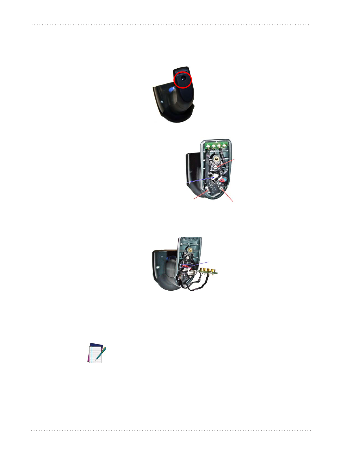
Getting Started
Connec
Screw
Screw
Screw
Pass-through
hole
Install the Batteries
To install or change the battery of your reader, you must:
1. With a screwdriver, unscrew the battery cover screw.
2. Unplug the three screws securing the battery holder, and unplug the white connector.
3. Carefully lift out the gold contacts circuit, and remove the battery holder while letting the
white connector pass through the hole in the battery holder (as shown in the picture
below).
4. Remove the old battery from its place (if present), and insert the new battery in the same
position.
5. Replace the battery holder, plug in the connector and return the contacts circuit to its previous location.
When inserting the new battery into the handle, take care to position the battery
and the connector as shown.
NOTE
16 Gryphon™ I GD4100/GM4100
Page 19

6. Insert the cover in the handle and screw it back into place.
Install the Interface Cable
For Corded versions, connect the reader cable by inserting the cable into the handle as shown in
Figure 1. To remove it, insert a paper clip into the rele
Figure 1. Connect/disconnect the cable
Install the Interface Cable
ase aperture, then unplug the cable.
RS-232 Serial Connection
Turn off power to the terminal/PC and connect the reader to the terminal/PC serial port via the
RS-232 cable as shown in Figure 2. If the terminal will not support POT (Power Off the
Terminal) to supply reader power, use the approved power supply (AC Adapter). Plug the AC
Adapter barrel connector into th
plug into a standard power outlet.
e socket on the RS-232 cable connector and the AC Adapter
Product Reference Guide 17
Page 20
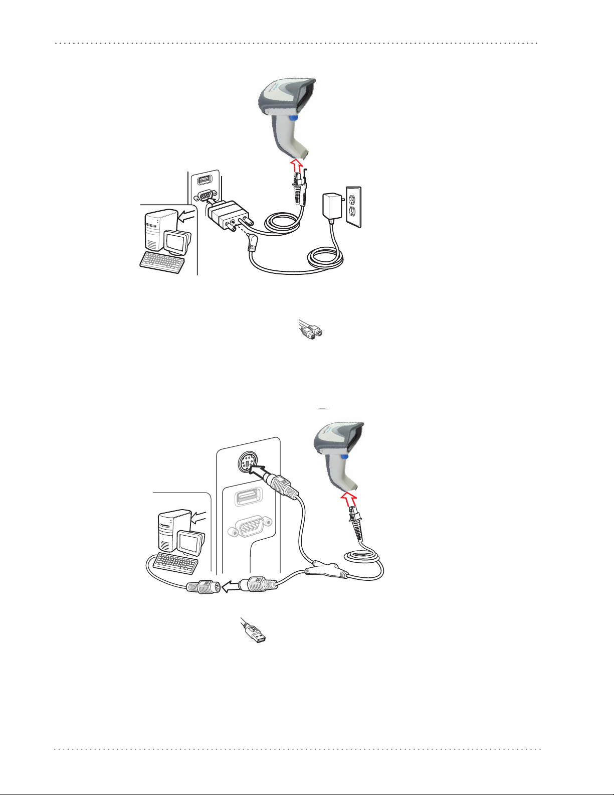
Getting Started
Figure 2. RS-232 Connection
Keyboard Wedge Connection
The Keyboard Wedge cable has a ‘Y’ connection from the reader. Connect the female to the
male end from the keyboard and the remaining end at the keyboard port at the terminal/PC.
Reference Figure 3.
Figure 3. Keyboard Wedge Interface connection
USB Connection
Connect the reader to a USB port on the terminal/PC using the correct USB cable for the
interface type you ordered. Reference Figure 4.
18 Gryphon™ I GD4100/GM4100
Page 21
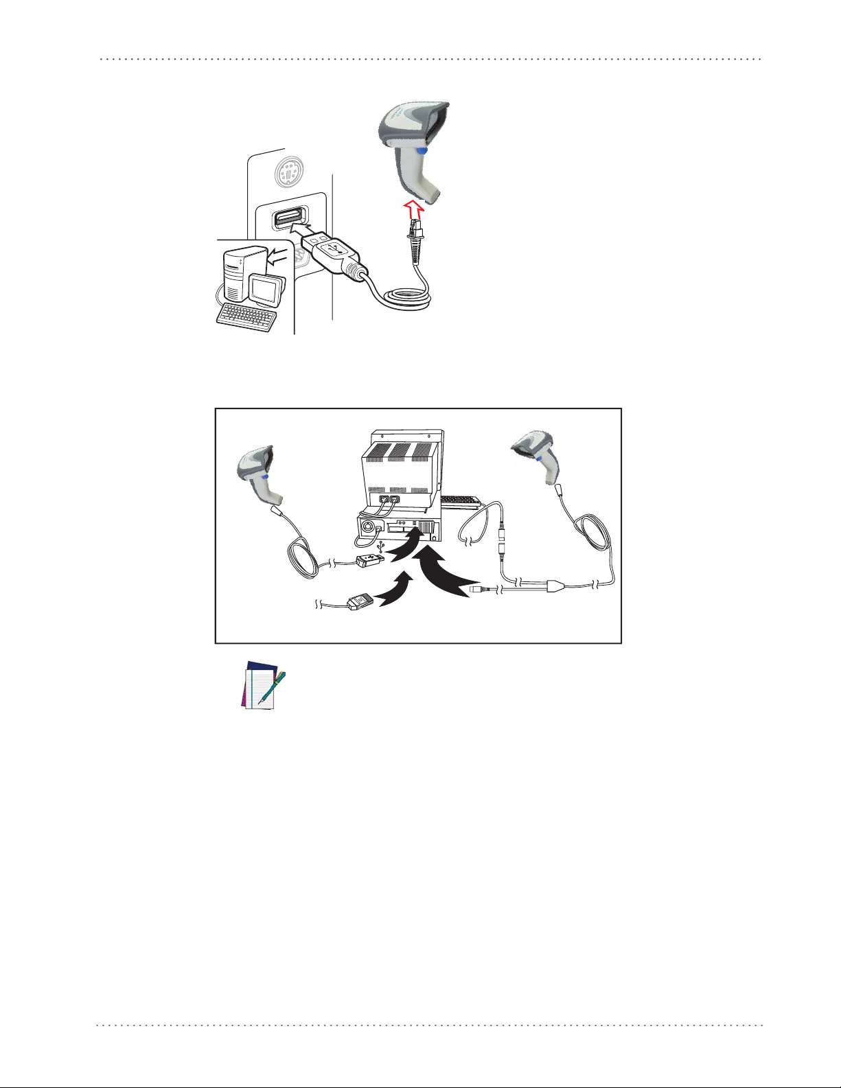
Install the Interface Cable
U
S
B
I
B
M
K
e
y
b
o
a
r
d
W
e
d
g
e
or...
or...
Figure 4. USB connection
Other connection types are described below and illustrated in Figure 5.
Figure 5. Other Interface Connections
Specific cables are required for connection to different hosts. The connectors illustrated above are examples only. Actual connectors may vary from
those illustrated, but the steps to connect the reader remain the same.
NOTE
RF Models
The power supply connects directly to the base (not on the cable's jack) for all configurations.
For all interfaces (except RS-232) a power supply is recommended but not necessary, because
the base can be powered from the Host. When the base is powered from the Host, select a slow
charge rate.
Product Reference Guide 19
Page 22

Getting Started
Standing
Horizontal
Configuring the Base Station
The base charger/station may be configured in desk application to hold the reader in two
different positions, either a horizontal or standing position, in order to provide the most
comfortable use depending on needs.
Changing the Base Station Position
The base station is configured by installing one of two sets of mechanical parts that come with
the cordless kit. The default mounts (shown below) provide three options: vertical (wall)
mounting, standing (45°), or horizontal mounting with a higher mechanical retention of the
scanner. Use the other mounts only for horizontal mounting, with lower retention of the
scanner. The different parts may be interchanged to customize retention preferences.
A tool such as a rigid pen or a flat screwdriver can be used to change the
mounts. Do not allow it to touch the contacts.
20 Gryphon™ I GD4100/GM4100
Page 23
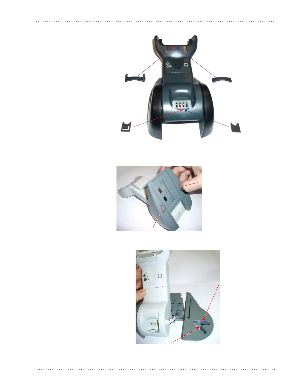
Configuring the Base Station
Tab
Tab
Horizontal
Standing
Horizontal
Only
Standing,
or Vertical
Horizontal
1. Insert the appropriate parts for the desired base station position, as shown below.
2. Using your thumbs, push open the plastic tabs on the bottom of the base to free the wing
holders.
3. The stand can now be repositioned in either horizontal or standing position.
Product Reference Guide 21
Page 24

Getting Started
Base
Station
I/F Cable
AC/DC
Adapter
DC Power
Cord
Wall plug
Connector
Connect the Base Station
Figure 6 shows how to connect the Base Station to a terminal, PC or other host device. Turn off
the host before connection and consult the manual for that equipment (if necessary) before
proceeding.
NOTE
Connect the interface cable before applying power to the Base Station.
Gryphon Mobile can also be Powered by the Terminal. The external power supply is
recommended but not necessary. When powered by the Terminal, the battery charger is automatically set as Slow charge.
Base Station Connection and Routing.
Fully insert the Power Cable and Interface (I/F) Cable
connectors into their respective ports in the underside of the Base Station (see Figure 6). Then
connect to an AC Adapter, and plug the AC power cord into the (wall) outlet.
Figure 6. Connecting the Base Station
Securing the DC Power Cord (Optional)
The DC power cord for the adapter can be secured to the bottom of the base in order to
maximize the mechanical retention of the cable itself. The routing of the power cord can be
changed to accommodate the base station positioning: horizontal, stand or wall mounting. The
cables can be looped around to the front of the Base Station, or fed directly out the back of the
Base Station, as shown in Figure 7 on page 23.
22 Gryphon™ I GD4100/GM4100
Page 25
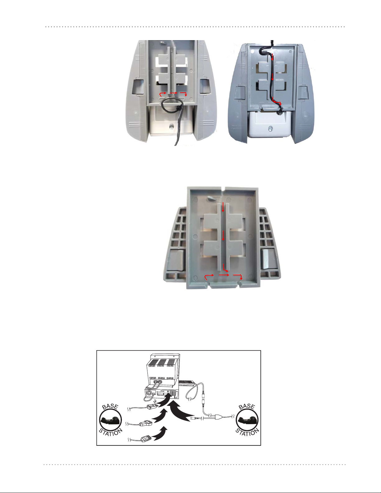
Configuring the Base Station
U
S
B
I
B
M
K
e
y
b
o
a
r
d
W
e
d
g
e
W
a
n
d
or...
or...
or...
Figure 7. Options for routing the DC cord
Please refer to the arrows depicted on the bottom of the base when placing the cables, detailed in
Figure 8.
Figure 8. Arrows showing routing
Host Connection.
Verify before connection that the reader’s cable type is compatible with your
host equipment. Most connections plug directly into the host device as shown below. Keyboard
Wedge interface cables have a ‘Y’ connection where its female end mates with the male end of
the cable from the keyboard and the remaining end at the keyboard port on the terminal/PC.
Figure 9. Connecting to the Host
Product Reference Guide 23
Page 26

Getting Started
Unlink
Insert
Paper Clip
Power Connection .
facing downwards (as shown in Figure 6) to prevent undue strain on the socket.
Gryphon Mobile can also be Powered by the Terminal. The external power supply is recommended but not necessary. When powered by the Terminal, the battery charger is
automatically set as Slow charge.
NOTE
Disconnecting the Cable.
on the base, as shown in Figure 10.
Figure 10. Disconnecting the Cable
Plug the AC Adapter in to an approved AC wall socket with the cable
To detach the cable, insert a paper clip or similar object into the hole
Linking the Reader to a Base Station
RF Devices
For RF devices, before configuring the interface it is necessary to link the handheld with the
base.
To link the handheld and the base, press the trigger to wake it and place it on the base. If the
reader was previously linked to another base,
before re-linking to the new base.
you must first scan the Unlink action command
24 Gryphon™ I GD4100/GM4100
Page 27
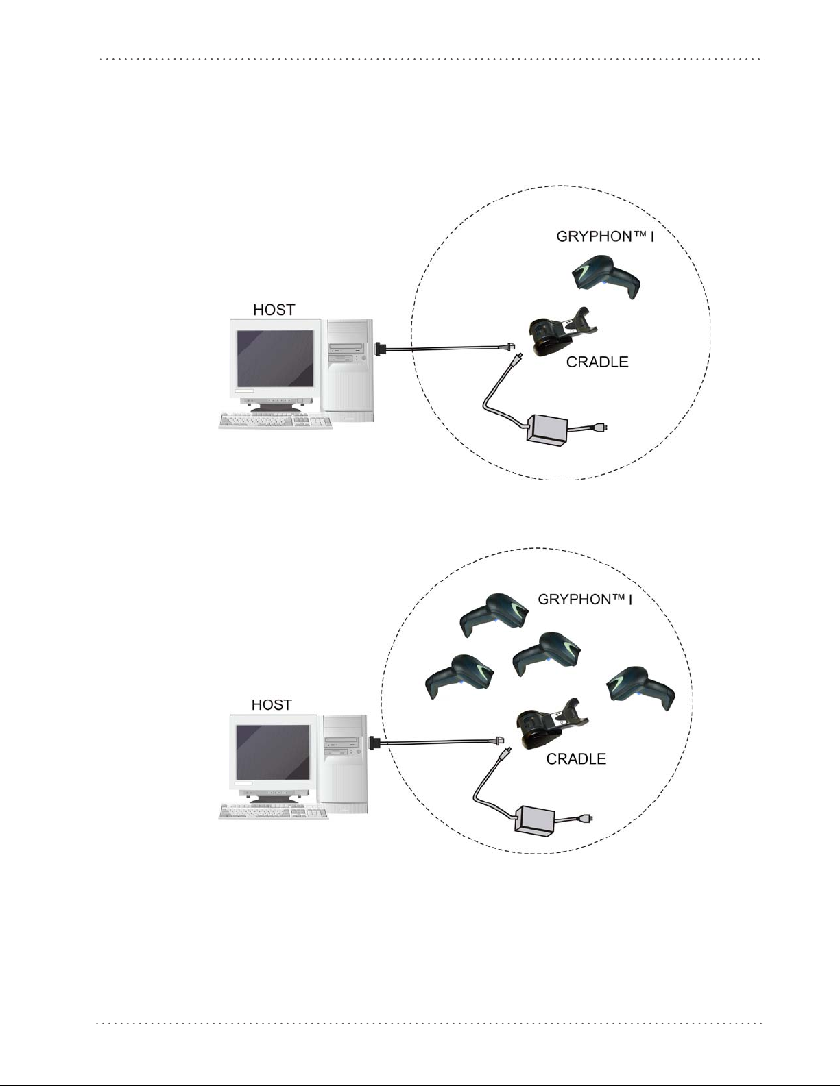
GRYPHON™ I System and Network Layouts
GRYPHON™ I System and Network Layouts
Stand Alone Layouts
Figure 11. Single Reader Layout
Figure 12. Multiple Reader Layout
In stand alone systems, each cradle is connected to a single Host.
Product Reference Guide 25
Page 28
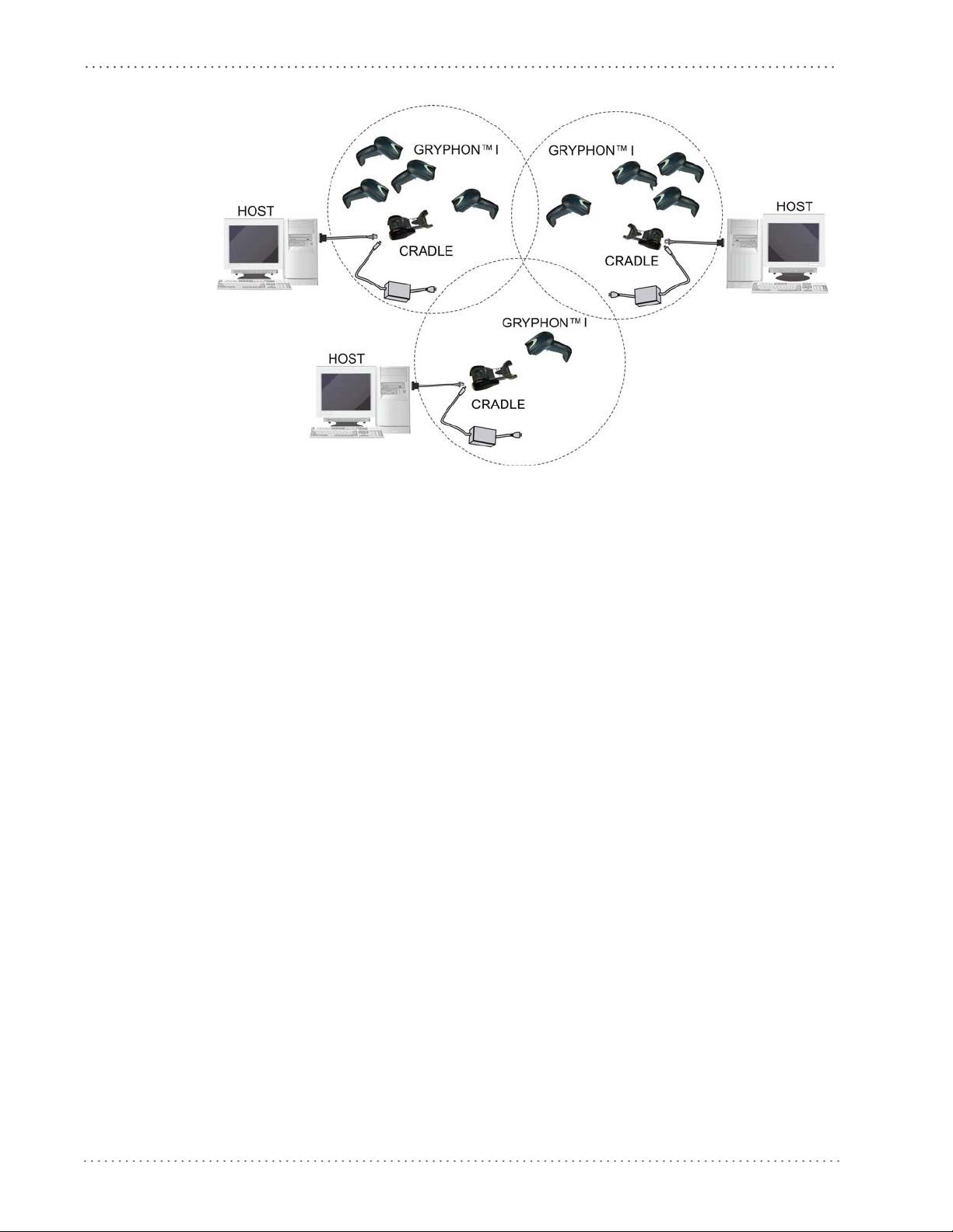
Getting Started
Figure 13. Multiple Stand Alone Layouts
Many stand alone connections can operate in the same physical area without interference,
provided all readers and cradles in the system have different addresses.
26 Gryphon™ I GD4100/GM4100
Page 29
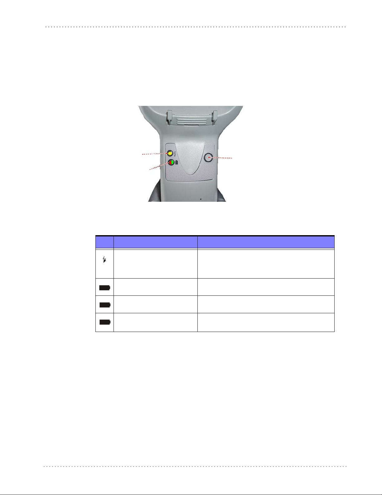
Using the BC40xx™ Radio Base
YELLOW LED
RED LED —
GREEN LED
BUTTON
Base LEDs
LEDs on the Gryphon I Base provide information about the Base’s status, as shown in Figure
14.
Using the BC40xx™ Radio Base
Figure 14
The following table describes the significance of each LED:
. Gryphon I Base LEDs
LED STATUS
Power on / Data
Yellow On = Base is powered
Yellow Blinking = Base receives data and
commands from the Host or the Reader.
Base Button
Charging Red On = the Battery is in progress.
Charge completed Green On = the Battery is completely charged.
Charging + Charge completed
See "Base Station Indications" on page 389 fo
The base contains a button, which is used primarily to perform a paging function. Pressing the
button causes a sound signal to be emitted by all scanners linked with this base, as long as the
scanner is awake (see "Powerdown Timeout" on page 164) and reception is enabled (s
Mode Timeout" on page 37).
The button can also be used to "force device connection" via the Datalogic Aladdin Software
tool (available for free down
load from the Datalogic website). See Aladdin for details.
Red and Green Blinking together = the Reader is not
orrectly placed onto the Base.
c
r more specific details on the LEDs.
ee "Sleep
Product Reference Guide 27
Page 30

Getting Started
Display
The Gryphon GM4100 is available with an optional Display. The Display features 4 lines and
16 characters, and offers icons and three additional keys to allow a better interaction with a
remote host.
Fonts, contrast, backlight and other parameters can be configured for
on page 60 and "Message Formatting" on page 379 for m
Figure 15. Gryphon™ I Display
ore information.
the Display. See "Display"
Programming
The reader is factory-configured with a set of default features standard. After scanning the
interface barcode from the Interfaces section, you can select other options and customize your
reader through use of the instructions and programming barcodes available in
corresponding features section for your interface, and also the Data Editing and Symbologies
chapters of this manual.
Using the Programming Barcodes
This manual contains feature descriptions and barcodes which allow you to reconfigure your
reader. Some programming barcode labels, like the "Restore Custom Default Configuration"on
page 30, require only the scan of that single label to enac
labels in this manual, however, require the reader to be placed
scanning them. Scan an ENTER/EXIT barcode once to enter Programming Mode. Once the
reader is in Programming Mode, you can scan a number of parameter settings before scanning
the ENTER/EXIT barcode a second time, which will then accept your changes, exit
Programming Mode and return the reader to normal operation.
There are some exceptions to the typical programming sequence described
above. Please read the description and setting instructions carefully when
configuring each programmable feature.
NOTE
the
t the change. Most of the programming
in Programming Mode prior to
28 Gryphon™ I GD4100/GM4100
Page 31

Select the Interface Type
Upon completing the physical connection between the reader and its host, proceed directly to
"Interfaces"on page 67 for information and programming for the in
connected to (for example: RS-232, Keyboard Wedge,
barcode in that section to select your system’s correct interface type.
Configure Interface Settings
If after scanning the interface barcode from the Interfaces section, your installation requires you
to select options to further customize your reader, turn to the appropriate sec
interface type as listed below:
• RS-232 ONLY Interface, starting on page 73
• Keyboard Interface, starting on page 99
• USB-OEM Interface, starting on page 113
• IBM 46XX Interface, starting on page 117
• Wand Emulation Interface, starting on page 123
Programming
terface type the reader is
USB, etc.) and scan the appropriate
tion for your
Product Reference Guide 29
Page 32

Getting Started
Transmit Software Version
Restore Custom Default Configuration
Configure Other Features
If your installation requires different programming than the standard factory default settings,
the following sections of this manual allow configuration of non-interface-specific settings you
might require:
.
General Features
indicators and other such universal settings.
Symbologies
allow you to enable/disable symbologies, set label lengths, require check digit, etc.
General Features includes programming for scanning, beeper and LED
.
Includes options concerning the barcode label types (symbologies). These settings
Software Version Transmission
The software version of the device can be transmitted over the RS-232 and Keyboard interfaces
by scanning the following label.
Resetting the Product Configuration to Defaults
Restore Custom Defaults
If you aren’t sure what programming options are in your imager, or you’ve changed some
options and want to restore the Custom Default Configuration that may have been saved in the
scanner, scan the Restore Custom Default Configuration barcode below. This will restore the
custom configuration for the currently active interface.
Custom defaults are based on the interface type. Configure the imager
for the correct interface before scanning this label.
NOTE
30 Gryphon™ I GD4100/GM4100
Page 33

Programming
Restore Factory Configuration
If you want to restore the Factory Configuration for your imager, scan either the Restore USA
Factory Configuration barcode or the Restore EU Factory Configuration barcode below. Both
labels restore the scanner configuration to the factory settings, including the interface type. The
USA label restores Label IDs to those historically used in the USA. The EU label restores Label
IDs to those historically used in Europe. The Label ID sets for USA and EU are shown in the
“Label ID” section on page 135 of this manual.
Restore USA Factory Configuration
Restore EU Factory Configuration
The programming section on the following pages lists the factory default settings for each of the
menu commands (indicated by shaded blocks and bold text).
Product Reference Guide 31
Page 34

Getting Started
NOTES
32 Gryphon™ I GD4100/GM4100
Page 35

Double Read Timeout
To prevent a double read of the same label, the Double Read Timeout sets the minimum time
allowed between reads of labels of the same symbology and data. If the unit reads a label and
sees the same label again within the Double Read Timeout, the second read of the label will be
ignored. Double Read Timeout does not apply to scan modes that require a trigger pull for each
label that is read.
Chapter 3
General Features
ENTER/EXIT PROGRAMMING MODE
Double Read Timeout = 0.1 Second
Double Read Timeout = 0.2 Second
Double Read Timeout = 0.3 Second
DEFAULT
Double Read Timeout = 0.4 Second
Product Reference Guide 33
Page 36

General Features
Double Read Timeout — continued
ENTER/EXIT PROGRAMMING MODE
Double Read Timeout = 0.6 Second
Double Read Timeout = 0.5 Second
Double Read Timeout = 0.8 Second
Double Read Timeout = 1 Second
Double Read Timeout = 0.7 Second
Double Read Timeout = 0.9 Second
34 Gryphon™ I GD4100/GM4100
Page 37

Label Gone Timeout
This feature sets the time after the last label segment is seen before the reader prepares for a new
label. The timeout can be set within a range of 10 milliseconds to 2,550 milliseconds (2.55
seconds) in 10ms increments. Label Gone Timeout does not apply to scan modes that require a
trigger pull for each label that is read
Follow these instructions to set this feature:
1. Determine the desired setting in milliseconds.
2. Divide the desired setting by 10 (setting is in 10ms increments). Pad the result with leading zeroes to yield three digits. For example: 0 = 000, 5 = 005, 20 = 020, etc.
3. Scan the ENTER/EXIT PROGRAMMING MODE barcode to enter Programming
de
.
Mo
4. Scan the barcode: SELECT LABEL GONE TIMEOUT SETTING.
Label Gone Timeout
5. Scan the appropriate three alpha-numeric characters from the keypad in A
pad representing the duration which was determined in the steps above. You will hear a
two-beep indication after the last character.
If you make a mistake before the last character, scan the CANCEL
barcode to abort and not save the entry string. You can then start
again at the beginning.
NOTE
6. Scan the ENTER/EXIT PROGRAMMING MODE barcode to exit Programming
Mode
.
This completes the procedure. See Table 1 for some examples of how to set this feature.
Tabl e 1. Timeout Setting Examples
STEP ACTION EXAMPLES
1 Desired Setting
Divide by 10 (and pad with
2
leading zer
oes)
50ms 150ms
005 015 180 255
1800ms (1.8
sec.)
ppendix E, Key-
50ms (2.55 sec.)
25
3 Scan ENTER/EXIT PROGRAMMING MODE
4 Scan SELECT LABEL GONE TIMEOUT SETTING
5
Scan Three Characters
From
Appendix E, Keypad
‘0’, ‘0’ and ‘5’ ‘0’, ‘1’ and ‘5’ ‘1’, ‘8’ and ‘0’ ‘‘2’, ‘5’ and ‘5’
6 Scan ENTER/EXIT PROGRAMMING MODE
Product Reference Guide 35
Page 38

General Features
016 = Timeout of 160 ms
Label Gone Timeout — cont.
ENTER/EXIT PROGRAMMING MODE
Select Label Gone Timeout Setting
Make a mistake? Scan the CANCEL barcode to abort and
not save the entry string. You can then start again at the
beginning.
CANCEL
DEFAULT
36 Gryphon™ I GD4100/GM4100
Page 39

Sleep Mode Timeout
Specifies the timeout value for the reader to enter low power Sleep Mode. When Sleep Mode is
enabled the reader cannot receive commands from the Host or base station.
Sleep Mode Timeout
In order for the reader to enter Sleep Mode, the following cond
Corded version .
Mobile version .
single, trigger multiple or trigger pulse are set, and when the reader is not charging the battery.
RS-232 interface and trigger single, trigger multiple or trigger pulse.
Sleep state is allowed only on the handheld (not on the base) when trigger
ENTER/EXIT PROGRAMMING MODE
itions must be met:
DEFAULT
Sleep Mode Timeout = Disable
Sleep Mode Timeout = 2 Seconds
Sleep Mode Timeout = 4 Seconds
Sleep Mode Timeout = 1 Second
Sleep Mode Timeout = 3 Seconds
Product Reference Guide 37
Page 40

General Features
Sleep Mode Timeout — continued
ENTER/EXIT PROGRAMMING MODE
Sleep Mode Timeout = 6 Seconds
Sleep Mode Timeout = 5 Seconds
Sleep Mode Timeout = 8 Seconds
Sleep Mode Timeout = 10 Seconds max.
Sleep Mode Timeout = 7 Seconds
Sleep Mode Timeout = 9 Seconds
38 Gryphon™ I GD4100/GM4100
Page 41

LED and Beeper Indicators
Power On Alert
Disables or enables the indication (from the Beeper) that the reader is receiving power.
ENTER/EXIT PROGRAMMING MODE
LED and Beeper Indicators
Power On Alert = Disable (No Audible Indication)
Power On Alert = Four Beeps
DEFAULT
Product Reference Guide 39
Page 42

General Features
DEFAULT
Good Read: When to Indicate
This feature specifies when the reader will provide indication (beep and/or flash its green LED)
upon successfully reading a barcode. Choices are:
• Good Read = Indicate after decode
• Good Read = Indicate after transmit
• Good Read = Indicate after CTS goes inactive, then active
.
This option, which uses CTS, is only valid for RS-232 interfaces.
NOTE
ENTER/EXIT PROGRAMMING MODE
Indicate Good Read = After Transmit
Indicate Good Read = After Decode
Indicate Good Read = After CTS Goes Inactive, Then
Active
40 Gryphon™ I GD4100/GM4100
Page 43

Good Read Beep Type
DEFAULT
Specifies whether the good read beep has a mono or bitonal beep sound.
LED and Beeper Indicators
ENTER/EXIT PROGRAMMING MODE
Good Read Beep Type = Mono
Good Read Beep Type = Bitonal
Product Reference Guide 41
Page 44

General Features
DEFAULT
Good Read Beep Frequency
Adjusts the good read beep to sound at a selectable low, medium or high frequency, selectable
from the list below. (Controls the beeper’s pitch/tone.)
ENTER/EXIT PROGRAMMING MODE
Good Read Beep Frequency = Low
Good Read Beep Frequency = Medium
Good Read Beep Length
Specifies the duration of a good read beep.
Good Read Beep Frequency = High
ENTER/EXIT PROGRAMMING MODE
42 Gryphon™ I GD4100/GM4100
Good Read Beep Length = 60 msec
Page 45

Good Read Beep Length — continued
ENTER/EXIT PROGRAMMING MODE
Good Read Beep Length = 80 msec
LED and Beeper Indicators
DEFAULT
Good Read Beep Length = 100 msec
Good Read Beep Length = 120 msec
Good Read Beep Length = 160 msec
Good Read Beep Length = 140 msec
Good Read Beep Length = 180 msec
Good Read Beep Length = 200 msec
Product Reference Guide 43
Page 46

General Features
Good Read Beep Volume
Selects the beeper volume (loudness) upon a good read beep. There are three selectable volume
levels.
ENTER/EXIT PROGRAMMING MODE
Good Read Beep Volume = Beeper Off
Good Read Beep Volume = Low
Good Read Beep Volume = High
Good Read Beep Volume = Medium
DEFAULT
44 Gryphon™ I GD4100/GM4100
Page 47

Good Read LED Duration
This feature specifies the amount of time that the Good Read LED remains on following a good
read. The good read LED on time can be set within a range of 10 milliseconds to 2,550
milliseconds (0.001 to 2.55 seconds) in 100ms increments.
Follow these instructions to set this feature:
1. Determine the desired setting in milliseconds. A setting of 0 means that the good read
LED stays on until the next time t
2. Divide the desired setting by 10 (setting is in 100ms increments). Pad the result with lead-
ing zeroes to yield three digits. For example: 0 = 000, 5 = 000, 20 = 020, etc.
3. Scan the ENTER/EXIT PROGRAMMING MODE barcode to enter Programming
de
.
Mo
4. Scan the barcode: SELECT GOOD READ LED DURATION SETTING.
5. Scan the appropriate three digits from the keypad in Appendix E, Keypad representing the
duration which was determined in the steps above. Y
after the last character.
LED and Beeper Indicators
he trigger is pulled.
ou will hear a two-beep indication
If you make a mistake before the last character, scan the CANCEL
barcode to abort and not save the entry string. You can then start
again at the beginning.
NOTE
6. Scan the ENTER/EXIT PROGRAMMING MODE barcode to exit Programming
Mode
.
This completes the procedure. See Table 2 for some examples of how to set this feature.
Tabl e 2. Good Read LED Duration Setting Examples
STEP ACTION EXAMPLES
Good Read LED
1 Desired Setting
Divide by 10 (and pad with
2
leading zer
oes)
stays on until
next trigger pull
(00)
000 002 015 255
20ms 150ms 2550ms (2.55 sec.)
3 Scan ENTER/EXIT PROGRAMMING MODE
4 Scan SELECT LABEL GONE TIMEOUT SETTING
5
Scan Three Characters
From
Appendix E, Keypad
‘0’, ‘0’ and ‘0’ ‘0’, ‘0’ and ‘2’ ‘0’, ‘1’ and ‘5’ ‘2’, ‘5’ and ‘5’
6 Scan ENTER/EXIT PROGRAMMING MODE
Product Reference Guide 45
Page 48

General Features
020 = Good Read LED
stays on for 2 seconds.
Good Read LED Duration — cont.
ENTER/EXIT PROGRAMMING MODE
Select Good Read LED Duration Setting
Make a mistake? Scan the CANCEL barcode to abort and
not save the entry string. You can then start again at the
beginning.
CANCEL
DEFAULT
NOTE
Indicators are dimmed during sleep.
46 Gryphon™ I GD4100/GM4100
Page 49

Scanning Features
Scan Mode
Selects the scan operating mode for the reader. Selections are:
Scanning Features
Trigger Single.
occurs:
- Scanning Active Time has elapsed
- a labe
- the trigger is released
This mode is associated with typical handheld reader operation: whe
scanning starts and the product scans until the trigger is released, or a label is read, or the
maximum Scanning Active Time has elapsed.
Trigger Hold Multiple .
the trigger is released or Scanning Active Time has elapsed. Reading a label does not disable
scanning. Double Read Timeout prevents undesired multiple reads of the same label while in
this mode.
Trigger Pulse Multiple.
Scanning Active Time has elapsed or the trigger has been released and pulled again. Double
Read Timeout
Flashing.
by Flash On Time and Flash Off Time. When Flash is ON the imager reads continuously; when
Flash is OFF scanning is deactivated.
When the trigger is pulled, scanning is activated until one of the following
l has been read
n the trigger is pulled,
When the trigger is pulled, scanning starts and the product scans until
When the trigger is pulled, continuous scanning is activated until
1
prevents undesired multiple reads of the same label while in this mode.
The reader flashes1 on and off regardless of the trigger status. Flash rate is controlled
Always On.
trigger is pulled, the reader acts as if it is in Tr i gg er Si n gl e Mode. Double Read Timeout
prevents undesired multiple reads of the same label
Stand Mode.
when an item is placed in the reader’s field of view. If the trigger is pulled, the reader acts as if it
in single read mode. Double Read Timeout
mode.
Trigger Object Sense.
to activate the decoder.
1. Controlled by Flash On Time.
No trigger pull is required to read a barcode. Scanning is continually on. If the
while in this mode.
No trigger pull is required to read a barcode. Scanning is turned on automatically
1
prevents undesired multiple reads while in this
This mode is similar to Stand Mode, except that a trigger pull is required
1
Product Reference Guide 47
Page 50

General Features
Scan Mode — continued
Scan Mode = Trigger Single
ENTER/EXIT PROGRAMMING MODE
DEFAULT
Scan Mode = Trigger Hold Multiple
Scan Mode = Trigger Pulse Multiple
Scan Mode = Always On
Scan Mode = Flashing
Scan Mode = Stand Mode
Scan Mode = Trigger Object Sense
48 Gryphon™ I GD4100/GM4100
Page 51

Stand Mode Triggered Timeout
This feature specifies the time to remain in Tr ig ge r S i ng le mode after the trigger is pulled while
in Stand Mode.
Scanning Features
This timeout is only used when the Scan M
Stand Mode.
NOTE
Stand Mode Triggered Timeout = 0.5 Seconds
This feature is valid only for corded models.
ENTER/EXIT PROGRAMMING MODE
ode is configured as
DEFAULT
Stand Mode Triggered Timeout = 2 Seconds
Stand Mode Triggered Timeout = 4 Seconds
Stand Mode Triggered Timeout = 1.5 Seconds
Stand Mode Triggered Timeout = 3 Seconds
Product Reference Guide 49
Page 52

General Features
Stand Mode Triggered Timeout — continued
ENTER/EXIT PROGRAMMING MODE
Stand Mode Triggered Timeout = 8 Seconds
Stand Mode Triggered Timeout = 6 Seconds
Stand Mode Triggered Timeout = Switch back to Trig-
ger Single on trigger pull
50 Gryphon™ I GD4100/GM4100
Page 53

Stand Detection
Specifies the behavior of the scanner when placed in a stand that contains autorecognition
hardware.
Switch to Stand Mode
Scanning Features
ENTER/EXIT PROGRAMMING MODE
Ignore Autorecognition
DEFAULT
Switch to Flashing
Switch to Always On
Product Reference Guide 51
Page 54

General Features
Stand Mode Sensitivity
Sets the sensitivity level for stand mode wakeup. Choices are low, medium and high.
Stand Mode Sensitivity = Medium
ENTER/EXIT PROGRAMMING MODE
Stand Mode Sensitivity = Low
DEFAULT
Stand Mode Sensitivity = High
52 Gryphon™ I GD4100/GM4100
Page 55

Scanning Active Time
This setting specifies the amount of time that the reader stays in scan ON state once the state is
entered. The range for this setting is from 1 to 255 seconds in 1-second increments.
Follow these instructions to set this feature:
1. Determine the desired setting.
2. Pad the result with leading zeroes to yield three digits. For example: 0 = 000, 5 = 005, 20
020,
=
3. Scan the ENTER/EXIT PROGRAMMING MODE barcode to enter Programming
Mode
.
4. Scan the barcode: SELECT SCANNING ACTIVE TIME SETTING.
5. Scan the appropriate three digits from the keypad in Appendix E, Keypad, that represent
the duration which was determined in the steps above. You will hear a two-beep indication after the last character.
Scanning Features
etc.
If you make a mistake before the last character, scan the CANCEL
barcode to abort and not save the entry string. You can then start
again at the beginning.
NOTE
6. Scan the ENTER/EXIT PROGRAMMING MODE barcode to exit Programming
Mode
.
This completes the procedure. See Table 3 for some examples of how to set this feature.
Tabl e 3. Scanning Active Time Setting Examples
STEP ACTION EXAMPLES
1 Desired Setting
2 Pad leading zero(es)
1 Second
001 090 180 255
90 Sec. (1.5
min.)
180 Sec. (3 min.)
3 Scan ENTER/EXIT PROGRAMMING MODE
4 Scan SELECT SCANNING ACTIVE TIME SETTING
5
Scan Three Characters
From
Appendix E, Keypad
‘0’, ‘0’ and ‘1’ ‘0’, ‘9’ and ‘0’ ‘1’, ‘8’ and ‘0’ ‘2’, ‘5’ and ‘5’
255 Seconds (4.25
.)
min
6 Scan ENTER/EXIT PROGRAMMING MODE
Product Reference Guide 53
Page 56

General Features
005 = Scanning is active for 5 Seconds
Scanning Active Time — cont.
ENTER/EXIT PROGRAMMING MODE
Select Scanning Active Time Setting
Make a mistake? Scan the CANCEL barcode to abort and
not save the entry string. You can then start again at the
beginning.
CANCEL
DEFAULT
54 Gryphon™ I GD4100/GM4100
Page 57

Flash On Time
This feature specifies the ON time for the indicator LED while in Flash Mode. The selectable
range is 100 to 9,900 milliseconds (0.1 to 9.9 seconds), in 100 millisecond increments.
Follow these instructions to set this feature.
1. Determine the desired setting in milliseconds.
2. Divide the desired setting by 100 (setting is in 100ms increments). Pad the result with
3. Scan the ENTER/EXIT PROGRAMMING MODE barcode to enter Programming
4. Scan the barcode: SELECT FLASH ON TIME SETTING.
leading
Mode
.
ze
roes to yield two digits. For example: 0 = 00, 5 = 05, 20 = 20, etc.
Flash On Time
5. Scan the appropriate two digits from
the keypad
duration which was determined in the steps above. Y
in Appendix E, Keypad representing the
ou will hear a two-beep indication
after the last character.
If you make a mistake before the last character, scan the CANCEL
barcode to abort and not save the entry string. You can then start
again at the beginning.
NOTE
6. Scan the ENTER/EXIT PROGRAMMING MODE barcode to exit Programming
Mode
.
This completes the procedure. See Table 4 for some examples of how to set this feature.
Tabl e 4. Flash On Time Setting Examples
STEP ACTION EXAMPLES
1 Desired Setting
500ms 1,000ms (1 sec.)
5200ms (5.2
sec.)
Divide by 100 (and pad
2
with leading ze
roes to yield
05 10 52 99
two digits)
900ms (9.9 sec.)
9,
3 Scan ENTER/EXIT PROGRAMMING MODE
4 Scan SELECT FLASH OFF TIME SETTING
Scan Two Characters From
5
Appendix E, Keypad
‘0’ and ‘5’ ‘1’ and ‘0’ ‘5’ and ‘2’ ‘9’ and ‘9’
6 Scan ENTER/EXIT PROGRAMMING MODE
Product Reference Guide 55
Page 58

General Features
10 = Flash is ON for 1 Second
Flash On Time — cont.
ENTER/EXIT PROGRAMMING MODE
Select Flash ON Time Setting
Make a mistake? Scan the CANCEL barcode to abort and
not save the entry string. You can then start again at the
beginning.
CANCEL
DEFAULT
56 Gryphon™ I GD4100/GM4100
Page 59

Flash Off Time
This feature specifies the OFF time for the indicator LED while in Flash Mode. The selectable
range is 100 to 9,900 milliseconds (0.1 to 9.9 seconds), in 100 millisecond increments.
Follow these instructions to set this feature.
1. Determine the desired setting in milliseconds.
2. Divide the desired setting by 100 (setting is in 100ms increments). Pad the result with
3. Scan the ENTER/EXIT PROGRAMMING MODE barcode to enter Programming
4. Scan the barcode: SELECT FLASH OFF TIME SETTING.
5. Scan the appropriate two digits from the keypad in Appendix E, Keypad, that represent
Flash Off Time
ze
leading
Mode
roes to yield two digits. For example: 0 = 00, 5 = 05, 20 = 20, etc.
.
the duration which was determined in the steps above. You will hear a two-beep indication after the last character.
If you make a mistake before the last character, scan the CANCEL
barcode to abort and not save the entry string. You can then start
again at the beginning.
NOTE
6. Scan the ENTER/EXIT PROGRAMMING MODE barcode to exit Programming
Mode
.
This completes the procedure. See Table 5 for some examples of how to set this feature.
Tabl e 5. Flash Off Time Setting Examples
STEP ACTION EXAMPLES
1 Desired Setting
500ms 1,000ms (1 sec.)
5200ms (5.2
sec.)
Divide by 100 (and pad
2
with leading ze
roes to yield
05 10 52 99
two digits)
3 Scan ENTER/EXIT PROGRAMMING MODE
4 Scan SELECT FLASH OFF TIME SETTING
900ms (9.9 sec.)
9,
Scan Two Characters From
5
Appendix E, Keypad
‘0’ and ‘5’ ‘1’ and ‘0’ ‘5’ and ‘2’ ‘9’ and ‘9’
6 Scan ENTER/EXIT PROGRAMMING MODE
Product Reference Guide 57
Page 60

General Features
06 = Flash is OFF for 600ms
Flash Off Time — cont.
ENTER/EXIT PROGRAMMING MODE
Select Flash OFF Time Setting
Make a mistake? Scan the CANCEL barcode to abort and
not save the entry string. You can then start again at the
beginning.
CANCEL
DEFAULT
58 Gryphon™ I GD4100/GM4100
Page 61

Green Spot Duration
Specifies the duration of the good read pointer beam after a good read.
Green Spot Duration
ENTER/EXIT PROGRAMMING MODE
Green Spot Duration = Disable (Green Spot is Off )
DEFAULT
Green Spot Duration = Short (300 msec)
Green Spot Duration = Long (800 msec)
Green Spot Duration = Medium (500 msec)
Product Reference Guide 59
Page 62

General Features
Lighter
Darker
DEFAULT
Display
Contrast
Read the code until the desired contrast is reached.
Font Size
ENTER/EXIT PROGRAMMING MODE
Font size = small
Font size = Medium
60 Gryphon™ I GD4100/GM4100
Font size = Large
Page 63

Backlight
DEFAULT
Display
ENTER/EXIT PROGRAMMING MODE
Display backlight = off
Display backlight = on
Product Reference Guide 61
Page 64

General Features
DEFAULT
Display Mode
The user can control the reader display behavior according to the following selections:
Local Echo mode: When a barcode is
• The code is sent to the Host.
• The reader display is cleared.
• The code is also sent to the reader display (Local Echo).
• The cursor is positioned after the last printed character on the reader display.
mal mode: When a barcode is read with the reader:
Nor
• The code is sent to the H
• The reader display is not cleared. Therefore if
reader screen it remains.
• Ther
Clear Di
• The code is sent to the Host.
• The reader display is cleared. Therefore if any previous data was displayed on the reader
• There is no Local Echo of the code to the reader display.
Host
e is no Local Echo to the reader display.
splay After Decode mode: When a barcode is read with the reader:
scre
en it is cancelled and the screen remains blank.
messages sent to the reader are always written to the reader display.
ost.
read with the reader:
any previous data was displayed on the
Normal mode
ENTER/EXIT PROGRAMMING MODE
Local Echo mode
Clear display after decode
62 Gryphon™ I GD4100/GM4100
Page 65

Display Timeout
Specifies how long the display will remain on after a display write. Display is forced on after any
display write or after any reading phase. Display and backlight are turned off after this timeout
expires.
Display Timeout = Disable
Display
ENTER/EXIT PROGRAMMING MODE
DEFAULT
Display Timeout = 2 Seconds
Display Timeout = 4 Seconds
Display Timeout = 1 Second
Display Timeout = 3 Seconds
Product Reference Guide 63
Page 66

General Features
Display Timeout (continued)
Display Timeout= 6 Seconds
ENTER/EXIT PROGRAMMING MODE
Display Timeout = 5 Seconds
Display Timeout = 8 Seconds
Display Timeout = 9.9 Seconds (9,900ms max.)
Display Timeout = 7 Seconds
Display Timeout = 9 Seconds
64 Gryphon™ I GD4100/GM4100
Page 67

Keypad Select
DEFAULT
3C3D3E
This parameter specifies the character that has to be sent from the scanner when one of the three
keys are pressed. For example, when key1 is pressed a 0x3C '<' character is sent.
Follow these instructions to set this feature:
1. Determine the desired setting.
2. Scan the ENTER/EXIT PROGRAMMING MODE barcode to enter Programming
3. Scan the barcode: DISPLAY KEYPAD SELECT.
4. Then read 3 HEX characters in the range 01-FE from the keypad in Appendix E, Keypad,
NOTE
.
Mode
corresponding to the left, center and right keys respectively.
If you make a mistake before the last character, scan the CANCEL barcode to abort and not save the entry string. You can then start again at
the beginning.
Keypad Select
Scan the ENTER/EXIT PROGRAMMING MODE barcode to exit Programming Mode.
ENTER/EXIT PROGRAMMING MODE
Enable Keypad Select
Make a mistake? Scan the CANCEL barcode to abort and
not save the entry string. You can then start again at the
beginning.
Disable Keypad
CANCEL
Product Reference Guide 65
Page 68

General Features
NOTES
66 Gryphon™ I GD4100/GM4100
Page 69

Interface Selection
Each reader model will support one of the following sets of host interfaces:
General Purpose Models
RS-232
RS-232 OPOS
USB
Keyboard Wedge
Wand Emulation
Retail Point of Sale Models
Chapter 4
Interfaces
RS-232
RS-232 OPOS
USB
IBM 46XX
Configuring the Interface
Scan the programming barcode from this section which selects the appropriate interface type
matching the system the reader will be connected to. Next, proceed to the corresponding
chapter in this manual (also listed in Table 6) to configure any desired settings and features
associated with that interface.
Unlike some other programming features and options, interface selections require that you scan only one programming barcode label. DO
NOT scan an ENTER/EXIT barcode prior to scanning an interface selection
barcode.
Some interfaces require the scanner to start in the disabled state when
powered up. If additional scanner configuration is desired while in this
NOTE
state, pull the trigger and hold it for five seconds. The scanner will
change to a state that allows programming with barcodes.
Product Reference Guide 67
Page 70

Interfaces
Tabl e 6. Available Interfaces
RS-232 FEATURES
RS-232 standard interface
Select RS232-STD
RS-232 Wincor-Nixdorf
Set RS-232
Select RS232-WN
Interface
Features
starting on
page 73
RS-232 for use with OPOS/UPOS/JavaPOS
Select RS-232 OPOS
USB Com to simulate RS-232 standard interface
Select USB-COM-STD
IBM
Select IBM-P5B
a
FEATURES
IBM-46xx Port 5B reader interface
Set IBM
Interface
Features
starting on
page 117
IBM-46xx Port 9B reader interface
Select IBM-P9B
USB-OEM FEATURES
Set USB-OEM
USB-OEM
(can be used for OPOS/UPOS/JavaPOS)
Select USB-OEM
Interface
Features
starting on
page 113
a. Download the correct USB Com driver from www.datalogic.com
68 Gryphon™ I GD4100/GM4100
Page 71

Configuring the Interface
KEYBOARD FEATURES
AT, PS/2 25-286, 30-286, 50, 50Z, 60, 70,
80, 90 & 95 w/Standard Key Encoding
Select KBD-AT
Keyboard Wedge for IBM AT PS2 with
standard key encoding but without
external keyboard
Select KBD-AT-NK
AT, PS/2 25-286, 30-286, 50, 50Z, 60, 70,
80, 90 & 95 w/Alternate Key
Select KBD-AT-ALT-NK
PC/XT w/Standard Key Encoding
Select KBD-IBM-3153
Select KBD-AT-ALT
Keyboard Wedge for IBM AT PS2 with
alternate key encoding but without
external keyboard
Select KBD-XT
Keyboard Wedge for IBM Terminal 3153
Set KEYBOARD
WEDGE
Interface
Features
starting on
page 99
Product Reference Guide 69
Page 72

Interfaces
KEYBOARD — cont. FEATURES
Keyboard Wedge for IBM Terminals
31xx, 32xx, 34xx, 37xx make only keyboard
Select KBD-IBM-M
Keyboard Wedge for IBM Terminals
31xx, 32xx, 34xx, 37xx make break keyboard
Select KBD-IBM-MB
Keyboard Wedge for DIGITAL Terminals VT2xx, VT3xx, VT4xx
Select KBD-DIG-VT
Set KEYBOARD
WEDGE
Interface
Features
starting on page
99
USB Keyboard with standard key encoding
Select USB Keyboard
USB Keyboard with alternate key encoding
Select USB Alternate Keyboard
USB Keyboard for Apple computers
Select USB-KBD-APPLE
WAND EMULATION FEATURES
Set WAND
Interface
Wand Emulation
Features
starting on page
Select WAND
123
70 Gryphon™ I GD4100/GM4100
Page 73

Global Interface Features
DEFAULT
The following interface features are configurable by all interface types. To set features specific to
your interface, turn to that section of this manual:
• RS-232 ONLY Interface on page 73
• Keyboard Interface on page 99
• USB-OEM Interface on page 113
• IBM 46XX Interface on page 117
• Wand Emulation Interface on page 123
Host Commands — Obey/Ignore
This option specifies whether the reader will obey or ignore host commands. When set to
ignore, the reader will ignore all host commands except for those necessary for:
•service mode
• flash programming mode
• keeping the interface active
• transmission of labels.
Global Interface Features
Host Commands = Ignore
ENTER/EXIT PROGRAMMING MODE
Host Commands = Obey
Product Reference Guide 71
Page 74

Interfaces
DEFAULT
USB Suspend Mode
This setting enables/disables the ability of USB interfaces to enter suspend mode.
ENTER/EXIT PROGRAMMING MODE
USB Suspend Mode = Disable
USB Suspend Mode = Enable
72 Gryphon™ I GD4100/GM4100
Page 75

RS-232 ONLY Interface
Introduction
Use the programming barcodes in this chapter if modifications to the standard RS-232 interface
settings are necessary to meet your system’s requirements. Additional settings which apply to
both the RS-232 and USB interfaces are available in Chapter 6, RS-232/USB-Com Interfaces.
RS-232 Standard Factory Settings
Reference Appendix C, Standard Defaults for a listing of standard factory settings.
Baud Rate
Baud rate is the number of bits of data transmitted per second. Set the reader's baud rate to
match the baud rate setting of the host device. With an improper baud rate setting, data may
not reach the host correctly.
Chapter 5
ENTER/EXIT PROGRAMMING MODE
Baud Rate = 1200
Baud Rate = 2400
Baud Rate = 4800
Product Reference Guide 73
Page 76

RS-232 ONLY Interface
DEFAULT
Baud Rate — continued
Baud Rate = 9600
ENTER/EXIT PROGRAMMING MODE
Baud Rate = 19,200
Baud Rate = 38,400
Baud Rate = 115,200
Baud Rate = 57,600
74 Gryphon™ I GD4100/GM4100
Page 77

Data Bits
Data Bits
This parameter allows the reader to interface with devices requiring a 7-bit or 8-bit ASCII
protocol for sending and receiving data.
ENTER/EXIT PROGRAMMING MODE
7 Data Bits
DEFAULT
Stop Bits
8 Data Bits
The stop bit(s) at the end of each transmitted character marks the end of transmission of one
character and prepares the receiving device for the next character in the serial data stream. The
number of stop bits selected (one or two) depends on the number the receiving terminal is
programmed to accommodate. Set the number of stop bits to match host device requirements.
ENTER/EXIT PROGRAMMING MODE
DEFAULT
1 Stop Bit
2 Stop Bits
Product Reference Guide 75
Page 78

RS-232 ONLY Interface
Parity
This feature specifies parity required for sending and receiving data. A parity check bit is the
most significant bit of each ASCII coded character. Select the parity type according to host
device requirements.
• Select None when no parity bit is required.
• Select Odd parity and the parity bit value is set to 0 or 1, based on data, to ensure that an
• Select Even parity and the parity bit value is set to 0 or 1, based on data, to ensure that an
odd number of 1 bits are contain
even numb
er of 1 bits are contained in the coded character.
ENTER/EXIT PROGRAMMING MODE
ed in the coded character.
DEFAULT
Parity = Even
Parity = None
Parity = Odd
76 Gryphon™ I GD4100/GM4100
Page 79

Handshaking Control
The data interface consists of an RS-232 port designed to operate either with or without the
hardware handshaking lines, Request to Send (RTS), and Clear to Send (CTS). Handshaking
Control includes the following options:
• RTS — RTS is asserted during transmissions. CTS is ignored.
• RTS/CTS — RTS is asserted during transmissions. CTS gates transmissions.
• RTS/XON/XOFF — RTS is asserted during transmissions. CTS is ignored. XON and
XOFF gate transmissi
• RTS On/CTS — RTS is always asserted. CTS gates transmissions.
• RTS/CTS Scan Control — RTS is asserted during transmissions. CTS gates transmissions
and contr
ols enable and disable state
Handshaking Control
ons.
of scanner.
ENTER/EXIT PROGRAMMING MODE
DEFAULT
Handshaking Control = RTS/CTS
Handshaking Control = RTS On/CTS
Handshaking Control = RTS
Handshaking Control = RTS/XON/XOFF
Handshaking Control = RTS/CTS Scan Control
Product Reference Guide 77
Page 80

RS-232 ONLY Interface
NOTES
78 Gryphon™ I GD4100/GM4100
Page 81

RS-232/USB-Com Interfaces
Introduction
The programming barcodes in this chapter allow modifications to the standard RS-232 and
USB-Com interfaces.
Standard Factory Settings
Reference Appendix C, Standard Defaults for a listing of standard factory settings.
Chapter 6
Product Reference Guide 79
Page 82

RS-232/USB-Com Interfaces
Intercharacter Delay
This parameter specifies the intercharacter delay between the end of one character and the
beginning of the next. The delay can be set within a range of zero (0) to 990 milliseconds in
10ms increments. A setting of zero specifies no delay.
To set the delay:
1. Determine the desired setting in milliseconds.
2. Divide the desired setting by 10 (setting is in 10ms increments). Pad the result with leading zeroes to yield two digits. For example: 0 = 00, 5 = 05, 20 = 20, etc.
3. Scan the ENTER/EXIT PROGRAMMING MODE barcode to enter Programming
.
de
Mo
4. Scan the barcode: SELECT INTERCHARACTER DELAY SETTING.
5. Scan the appropriate two digits from the keypad in Appendix E, Keypad, that represent
the duration which was determined in the steps above. You will hear a two-beep indication after the last character.
If you make a mistake before the last character, scan the CANCEL
barcode to abort and not save the entry string. You can then start
again at the beginning.
NOTE
6. Scan the ENTER/EXIT PROGRAMMING MODE barcode to exit Programming
Mode
.
This completes the procedure. See Table 7 for some examples of how to set this feature.
Tabl e 7. Intercharacter Delay Setting Examples
STEP ACTION EXAMPLES
1 Desired Setting
Divide by 10 (and pad with
2
leading zer
3 Scan ENTER/EXIT PROGRAMMING MODE
4 Scan SELECT INTERCHARACTER DELAY SETTING
Scan Two Characters From
5
Appendix E, Keypad
oes to yield two-
digits)
50ms 150ms 600ms 850ms
05 15 60 85
‘0’ and ‘5’ ‘5’ and ‘0’ 0’ and ‘0’ ‘8’ and ‘5’
6 Scan ENTER/EXIT PROGRAMMING MODE
80 Gryphon™ I GD4100/GM4100
Page 83

Intercharacter Delay — cont.
00 = No Intercharacter Delay
ENTER/EXIT PROGRAMMING MODE
Select Intercharacter Delay Setting
Intercharacter Delay
Intercharacter Delay = No Delay
Make a mistake? Scan the CANCEL barcode to abort and
not save the entry string. You can then start again at the
beginning.
DEFAULT
CANCEL
Product Reference Guide 81
Page 84

RS-232/USB-Com Interfaces
DEFAULT
Beep On ASCII BEL
When this parameter is enabled, the reader issues a beep when a <BEL> character is detected on
the RS-232 serial line. <BEL> is issued to gain a user's attention to an illegal entry or other
important event.
Beep On ASCII BEL = Disable
ENTER/EXIT PROGRAMMING MODE
DEFAULT
Beep On Not on File
This option enables/disables the action of the reader to sound a three beep sequence upon
receiving a Not-On-File (NOF) host command.
Beep On Not On File = Disable
Beep On ASCII BEL = Enable
ENTER/EXIT PROGRAMMING MODE
82 Gryphon™ I GD4100/GM4100
Beep On Not On File = Enable
Page 85

ACK NAK Options
This enables/disables the ability of the reader to support the RS-232 ACK/NAK protocol.
When configured, the reader and/or host sends an “ACK” when it receives data properly, and
sends “NAK” when the data is in error.
Options are:
•Disable
• Enable for label transmission — The reader expects an ACK/NAK response from the host
when a
Enable for host-command acknowledge — The reader will respond with ACK/NAK
•
when t
• Enable for label transmission and host-command acknowledge
ACK NAK Options
label is sent.
he host sends a command.
ENTER/EXIT PROGRAMMING MODE
DEFAULT
ACK/NAK Protocol = Enable for label transmission
ACK/NAK Protocol = Enable for label transmission and
host-command acknowledge
ACK/NAK Protocol = Disable ACK/NAK
ACK/NAK Protocol = Enable for host-command
acknowledge
Product Reference Guide 83
Page 86

RS-232/USB-Com Interfaces
ACK Character
This setting specifies an ASCII character or hex value to be used as the ACK character. ASCII
characters or any hex value from 0 to 0xFF can be selected.
To set this feature:
1. Determine the desired character or value.
Use the ASCII Chart on the inside back cover of this manual to find the hex equivalent
2.
for the desired character/value.
3. Scan the ENTER/EXIT PROGRAMMING MODE barcode to enter Programming
Mo
NOTE
de
.
Setting to previously defined characters such as XON, XOFF,
or host commands conflicts with normal operation of these
characters. 8-bit data is not recognized when the option
has been set as 7 Data Bits.
Bits
Data
4. Scan the barcode: SELECT ACK CHARACTER SETTING.
5. Scan the appropriate two alpha-numeric characters from the keypad in Appendix E,
pad, that represent the desired character/value in step 1 above. The second character will
cause a two-beep indication.
6. Scan the ENTER/EXIT PROGRAMMING MODE barcode to exit Programming
de
.
Mo
This completes the procedure. See Table 8 for some examples of how to set this feature.
Tabl e 8. ACK Character Setting Examples
STEP ACTION EXAMPLES
1 Desired Character/Value
2 Hex equivalent
ACK $ @ >
0x06 0x24 0x40 0x3E
3 Scan ENTER/EXIT PROGRAMMING MODE
4 Scan SELECT ACK CHARACTER SETTING
Scan Two Characters From
5
Appendix E, Keypad
‘0’ and ‘6’ ‘2’ and ‘4’ ‘4’ and ‘0’ ‘3’ AND ‘E’
Key-
6 Scan ENTER/EXIT PROGRAMMING MODE
84 Gryphon™ I GD4100/GM4100
Page 87

ACK Character — cont.
0x06 ‘ACK’ Character
Select ACK Character Setting
DEFAULT
ACK NAK Options
ENTER/EXIT PROGRAMMING MODE
Product Reference Guide 85
Page 88

RS-232/USB-Com Interfaces
NAK Character
This setting specifies an ASCII character or hex value to be used as the NAK character. ASCII
characters or any hex value from 0 to 0xFF can be selected.
To set this feature:
1. Determine the desired character or value.
Use the ASCII Chart on the inside back cover of this manual to find the hex equivalent
2.
for the desired character/value.
3. Scan the ENTER/EXIT PROGRAMMING MODE barcode to enter Programming
Mo
NOTE
de
.
Setting to previously defined characters such as XON, XOFF,
or host commands conflicts with normal operation of these
characters. 8-bit data is not recognized when the option
has been set as 7 Data Bits.
Bits
Data
4. Scan the barcode: SELECT NAK CHARACTER SETTING.
5. Scan the appropriate two alpha-numeric characters from the keypad in Appendix E,
pad, that represent the desired character/value in step 1 above. The second character will
cause a two-beep indication.
6. Scan the ENTER/EXIT PROGRAMMING MODE barcode to exit Programming
de
.
Mo
This completes the procedure. See Table 9 for some examples of how to set this feature.
Tabl e 9. NAK Character Setting Examples
STEP ACTION EXAMPLES
1 Desired Character/Value
2 Hex equivalent
NAK $ @ >
0x15 0x24 0x40 0x3E
3 Scan ENTER/EXIT PROGRAMMING MODE
4 Scan SELECT ACK CHARACTER SETTING
Scan Two Characters From
5
Appendix E, Keypad
‘1’ and ‘5’ ‘2’ and ‘4’ ‘4’ and ‘0’ ‘3’ AND ‘E’
Key-
6 Scan ENTER/EXIT PROGRAMMING MODE
86 Gryphon™ I GD4100/GM4100
Page 89

NAK Character — cont.
0x15 ‘NAK’ Character
Select NAK Character Setting
DEFAULT
ACK NAK Options
ENTER/EXIT PROGRAMMING MODE
Product Reference Guide 87
Page 90

RS-232/USB-Com Interfaces
ACK NAK Timeout Value
This option specifies the amount of time the reader waits for an ACK character from the host
following label transmission. The selectable timeout range is 200 milliseconds to 15,000ms (15
seconds) in 200ms increments. A selection of 0 disables the timeout.
To set this value:
1. Determine the desired setting in milliseconds.
2. Divide the desired setting by 200 (setting is in 200ms increments). Pad the result with
leading
3. Scan the ENTER/EXIT PROGRAMMING MODE barcode to enter Programming
Mode
4. Scan the barcode: SELECT ACK NAK TIMEOUT VALUE SETTING.
5. Scan the appropriate two digits from the keypad in Appendix E, Keypad, that represent
the duration which was determined in the steps above. You will hear a two-beep indication after the last character.
ze
.
roes to yield two digits. For example: 0 = 00, 5 = 05, 20 = 20, etc.
If you make a mistake before the last character, scan the CANCEL
barcode to abort and not save the entry string. You can then start
again at the beginning.
NOTE
6. Scan the ENTER/EXIT PROGRAMMING MODE barcode to exit Programming
Mode
.
This completes the procedure. See Table 10 for some examples of how to set this feature.
Tabl e 10. ACK NAK Timeout Value Setting Examples
STEP ACTION EXAMPLES
1 Desired Setting
2 Divide by 200
200ms 1,000ms (1 sec.)
01 05 26 75
5200ms (5.2
sec.)
3 Scan ENTER/EXIT PROGRAMMING MODE
4 Scan SELECT ACK NAK TIMEOUT VALUE SETTING
Scan Two Characters From
5
Appendix E, Keypad
‘0’ and ‘1’ ‘0’ and ‘5’ ‘2’ and ‘6’ ‘7’ and ‘5’
,000ms (1 sec.)
15
6 Scan ENTER/EXIT PROGRAMMING MODE
88 Gryphon™ I GD4100/GM4100
Page 91

ACK NAK Timeout Value — cont.
DEFAULT
01 ACK NAK Timeout value is 200ms
ENTER/EXIT PROGRAMMING MODE
Select ACK NAK Timeout Value Setting
Make a mistake? Scan the CANCEL barcode to abort and
not save the entry string. You can then start again at the
beginning.
ACK NAK Options
CANCEL
Product Reference Guide 89
Page 92

RS-232/USB-Com Interfaces
ACK NAK Retry Count
This feature specifies the number of times the reader retries a label transmission due to a retry
condition. The selectable range is from 1 to 254 retries. A selection of 0 disables the count, and
a selection of 255 specifies unlimited retries.
To set this feature:
1. Determine the desired setting.
2. Pad the number with leading zeroes to yield three digits. For example: 0 = 000, 5 = 005,
= 02
20
3. Scan the ENTER/EXIT PROGRAMMING MODE barcode to enter Programming
Mode
4. Scan the barcode: SELECT ACK NAK RETRY COUNT SETTING.
5. Scan the appropriate three digits from the keypad in Appendix E, Keypad, that represent
the number which was determined in the steps above. Y
after the last character.
0, etc.
.
ou will hear a two-beep indication
If you make a mistake before the last character, scan the CANCEL
barcode to abort and not save the entry string. You can then start
again at the beginning.
NOTE
6. Scan the ENTER/EXIT PROGRAMMING MODE barcode to exit Programming
Mode
.
This completes the procedure. See Table 11 for some examples of how to set this feature.
Tabl e 11. ACK NAK Retry Count Setting Examples
STEP ACTION EXAMPLES
1 Desired Setting
2 Pad with leading zero(es)
Disable Retry
Count
000 003 054 255
3 Retries 54 Retries Unlimited Retries
3 Scan ENTER/EXIT PROGRAMMING MODE
4 Scan SELECT ACK NAK RETRY COUNT SETTING
5
Scan Three Characters
om
Appendix E, Keypad
Fr
‘0’, ‘0’ and ‘0’ ‘0’, ‘0’ and ‘3’ ‘0’, ‘5’ and ‘4’ ‘2’, ‘5’ and ‘5’
6 Scan ENTER/EXIT PROGRAMMING MODE
90 Gryphon™ I GD4100/GM4100
Page 93

ACK NAK Retry Count — cont.
003 = 3 Retries
ENTER/EXIT PROGRAMMING MODE
Select ACK NAK Retry Count Setting
Make a mistake? Scan the CANCEL barcode to abort and
not save the entry string. You can then start again at the
beginning.
ACK NAK Options
CANCEL
DEFAULT
Product Reference Guide 91
Page 94

RS-232/USB-Com Interfaces
ACK NAK Error Handling
This feature specifies the method the reader uses to handle receive errors detected while waiting
for an ACK character from the host.
Options are:
• Ignore errors detected
• Process error as valid ACK character
• Process error as valid NAK character
ENTER/EXIT PROGRAMMING MODE
DEFAULT
ACK NAK Error Handling = Process Error as Valid ACK
Character
ACK NAK Error Handling = Ignore Errors Detected
ACK NAK Error Handling = Process Error as
Valid NAK Character
92 Gryphon™ I GD4100/GM4100
Page 95

Indicate Transmission Failure
This option enables/disables the reader’s ability to sound an error beep to indicate a
transmission failure while in ACK/NAK mode
ENTER/EXIT PROGRAMMING MODE
Indicate Transmission Failure
.
Indicate Transmission Failure = Disable Indication
DEFAULT
Indicate Transmission Failure = Enable Indication
Product Reference Guide 93
Page 96

RS-232/USB-Com Interfaces
Disable Character
Specifies the value of the RS-232 host command used to disable the reader.
ASCII characters or any hex value from 0 to 0xF
Setting to previously defined characters such as XON, XOFF,
or host commands conflicts with normal operation of these
characters. 8-bit data is not recognized when the option
Bits
NOTE
has been set as 7 Data Bits.
F can be selected.
Data
To set the value:
1. Determine the desired character or value. A setting of 0xFF indicates the Disable Charac-
ter is not used (not avail
able).
2. Use the ASCII Chart on the inside back cover of this manual to find the hex equivalent
for the desired character/value.
3. Scan the ENTER/EXIT PROGRAMMING MODE barcode to enter Programming
de
.
Mo
4. Scan the barcode: SELECT DISABLE CHARACTER SETTING.
5. Scan the appropriate two alpha-numeric characters from the keypad in Appendix E,
Keypad, that represent the desired character/value in step 1 above. The second character will
cause a two-beep indication.
6. Scan the ENTER/EXIT PROGRAMMING MODE barcode to exit Programming
de
.
Mo
This completes the procedure. See Table 12 for some examples of how to set this feature.
Tabl e 12. Disable Character Setting Examples
STEP ACTION EXAMPLES
1 Desired character/value
2 Hex equivalent
‘d’ ‘}’ ‘D’
0x64 0x7D 0x44 0xFF
3 Scan ENTER/EXIT PROGRAMMING MODE
4 Scan SELECT DISABLE CHARACTER VALUE SETTING
Scan Two Characters From
5
Appendix E, Keypad
‘6’ and ‘4’ ‘7’ and ‘D’ ‘4’ and ‘4’ ‘F’ AND ‘F’
6 Scan ENTER/EXIT PROGRAMMING MODE
Disable Command
Not Used
94 Gryphon™ I GD4100/GM4100
Page 97

Disable Character — cont.
0x44 = Disable Character is ‘D’
Select Disable Character Setting
DEFAULT
Disable Character
ENTER/EXIT PROGRAMMING MODE
Product Reference Guide 95
Page 98

RS-232/USB-Com Interfaces
Enable Character
Specifies the value of the RS-232 host command used to enable the reader.
ASCII characters or any hex value from 0 to 0xF
Setting to previously defined characters such as XON, XOFF,
or host commands conflicts with normal operation of these
characters. 8-bit data is not recognized when the option
Bits
NOTE
has been set as 7 Data Bits.
F can be selected.
Data
To set this feature:
Determine the desired character or value. A setting of 0xFF indicates the Enable Character is
not used
(not available).
1. Determine the desired character or value.
Use the ASCII Chart on the inside back cover of this manual to find the hex equivalent
2.
for the desired character/value.
3. Scan the ENTER/EXIT PROGRAMMING MODE barcode to enter Programming
de
.
Mo
4. Scan the barcode: SELECT ENABLE CHARACTER SETTING.
5. Scan the appropriate two alpha-numeric characters from the keypad in Appendix E,
Keypad, that represent the desired character/value in step 2 above. The second character will
cause a two-beep indication.
6. Scan the ENTER/EXIT PROGRAMMING MODE barcode to exit Programming
de
.
Mo
This completes the procedure. See Table 13 for some examples of how to set this feature.
Tabl e 13. Enable Character Setting Examples
STEP ACTION EXAMPLES
1 Desired character/value
2 Hex equivalent
‘e’ ‘}’ ‘E’
0x65 0x7D 0x45 0xFF
3 Scan ENTER/EXIT PROGRAMMING MODE
4 Scan SELECT DISABLE CHARACTER VALUE SETTING
Scan Two Characters From
5
Appendix E, Keypad
‘6’ and ‘5’ ‘7’ and ‘D’ ‘4’ and ‘5’ ‘F’ AND ‘F’
6 Scan ENTER/EXIT PROGRAMMING MODE
Enable Command
Not Used
96 Gryphon™ I GD4100/GM4100
Page 99

Enable Character — cont.
0x45 = Enable Character is ‘E’
Select Enable Character Setting
DEFAULT
Enable Character
ENTER/EXIT PROGRAMMING MODE
Product Reference Guide 97
Page 100

RS-232/USB-Com Interfaces
NOTES
98 Gryphon™ I GD4100/GM4100
 Loading...