

Page 1
GRYPHON D432/D412Plus
Barcode Reader
Product Reference Guide
Page 2

Datalogic Scanning, Inc.
959 Terry Street
Eugene, Oregon 97402
Telephone: (541) 683-5700
Fax: (541) 345-7140
An Unpublished Work - All rights reserved. No part of the conte
nts of this documentation or the procedures described
therein may be reproduced or transmitted in any form or by any means without prior written permission of Datalogic
Scanning, Inc. or its subsidiaries or affiliates ("Datalogic" or “Datalogic Scanning”). Owners of Datalogic products are
hereby granted a non-exclusive, revocable license to reproduce and transmit this documentation for the purchaser's own
internal business purposes. Purchaser shall not remove or alter any proprietary notices, including copyright notices, contained in this documentation and shall ensure that all notic
es appear on any reproductions of the documentation.
Should future revisions of this manual be published, you can acquire printed versions by contacting your Datalogic representative. Electronic versions may either be downloadable from the Datalogic website (www.scanning.datalogic.com) or
vided on appropriate media. If you visit our website and would like to make comments or suggestions about this or
pro
other Datalogic publications, please let us know via the "Contact Datalogic" page.
Disclaimer
Datalogic has taken reasonable measures to provide information
in this manual that is complete and accurate, however,
Datalogic reserves the right to change any specification at any time without prior notice.
Datalogic is a registered trademark of Datalogic S.p.A. in many countries and the Datalogic logo is a trademark of Datalogic S.p.A. All other brand and product names referred to herein may be trademarks of their respective owners.
®
Microsoft Windows
, Windows® 2000, Windows®CE, Windows® NT, Windows® XP and the Windows logo are registered
trademarks of Microsoft Corporation.
Patents
This product is covered by one or more of the following patents:
US Pat.: 6,512,218 B1; 6,808,114 B1; 6,877,664 B1; 6,997,385 B2; 7,053,954 B1; 7,102,116 B2; 7,282,688 B2; 7,387,246 B2.
European Pat.: 996,284 B1; 999,514 B1; 1,128,315 B1; 1,396,811 B1.
Additional patents pending.
Page 3

Table of Contents
Preface: About this Guide............................................................................................................................................................. 3
How to Use this Manual ...........................................................................................................................................................................................................................3
Registering Your Datalogic Product ...............................................................................................................................................................................3
Document Conventions ..........................................................................................................
General View .................................................................................................................................................................................................................................................4
Compliance ...................................................................................................................................................................................................................................................4
CE Compliance ..................................................................................................................
FCC Compliance .................................................................................................................
Laser Safety ....................................................................................................................
LED Illuminator ....................................................................................................................................................................................................................... 5
Aiming System ........................................................................................................................................................................................................................5
WEEE Compliance ..................................................................................................................................................................................................................9
Power Supply .......................................................................................................................................................................................................................10
Service and Support ..........................................................................................................................................................................................................10
Chapter 1. Introduction.............................................................................................................................................................. 11
Gryphon D432/D412Plus Family Description ............................................................................................................................................................................... 11
Package Contents ....................................................................................................................................................................................................................................11
Configuration Methods .........................................................................................................................................................................................................................12
Reading Configuration Codes ......................................................................................................
Using Datalogic Aladdin™ .........................................................................................................................................................................................................12
Sending Configuration Strings from Host ...........................................................................................................................................................................12
Chapter 2. Using the Gryphon D432/412Plus .......................................................................................................................... 13
Aiming System ..........................................................................................................................................................................................................................................13
Normal Operation ....................................................................................................................................................................................................................................14
Image Capturing ............................................................................................................................................................................................................................ 15
Basic Configuration Parameters..................................................................................................
Advanced Configuration Parameters .........................................................................................................................................................................15
Autoscanning .................................................................................................................................................................................................................................16
Normal Mode......................................................................................................................
Pattern Mode ........................................................................................................................................................................................................................16
Defining Data Formatting ..........................................................................................................................................................................................................16
Concatenation ..................................................................................................................
................................................................................................................3
................................................................................................................5
..............................................................................................................5
.....................................................................................................................5
............................................................................................12
.................................................................................. 15
.................................................................................................. 16
...................................................................................................17
Chapter 3. Initial Setup............................................................................................................................................................... 19
RS-232 Interface Selection ......................................................................................................................................................................................................... 19
Wedge Interface Selection .........................................................................................................................................................................................................20
USB Interface Selection .........................................................................................................
IBM PORT 9B/PORT 5B/IBM USB ......................................................................................................
......................................................................................................20
..............................................................................23
Chapter 4. Configuration Using Code Symbols ....................................................................................................................... 25
Default Settings ........................................................................................................................................................................................................................................ 26
Changing Default Settings .......................................................................................................
Extended Header/Terminator Keys ................................................................................................
Concatenation Options ..........................................................................................................
Advanced Data Format ...........................................................................................................
Format Definition ..............................................................................................................
FIELD EXTRACTION BY CHARACTER ............................................................................................................................................................................95
FIELD EXTRACTION BY POSITION ................................................................................................................................................................................. 96
ADD NEW STRING ..............................................................................................................................................................................................................97
STRING INSERTION ............................................................................................................................................................................................................. 99
String Insertion Procedure ............................................................................................................................................................................................100
STRING DELETION............................................................................................................................................................................................................. 101
String Deletion Procedure............................................................................................................................................................................................. 102
STRING SUBSTITUTION ................................................................................................................................................................................................... 103
FIELD DELETION ................................................................................................................................................................................................................105
Match Conditions ...............................................................................................................
Format Enable/Disable ..........................................................................................................
Mismatch Result ...........................................................................................................................................................................................................................112
.................................................................................................30
........................................................................................45
..........................................................................................55
............................................................................................................... 91
.................................................................................................92
.........................................................................................................109
....................................................................................................110
Product Reference Guide
1
Page 4

Contents
Chapter 5. References.............................................................................................................................................................. 113
RS-232 — USB COM ....................................................................................................................................................................................................................113
ACK/NACK Protocol .........................................................................................................................................................................................................113
RX Timeout ..........................................................................................................................................................................................................................113
USB Keyboard ....................................................................................................................
Keyboard Speed................................................................................................................................................................................................................ 113
Code Selection .............................................................................................................................................................................................................................114
Issue Identical Codes ..........................................................................................................
Reading Parameters ...................................................................................................................................................................................................................114
Safety Time.....................................................................................................................
Configuration Editing Commands ........................................................................................................................................................................................114
Chapter 6. Test Code Symbols ................................................................................................................................................ 115
Chapter 7. Maintenance .......................................................................................................................................................... 117
Chapter 8. Technical Features................................................................................................................................................. 119
Gryphon D432/D412Plus Family Common Features ..........................................................................................................................................119
Indicators ......................................................................................................................
Gryphon D432/D412Plus LED Indicators .................................................................................................................................................................124
Beeper ...................................................................................................................................................................................................................................124
Good Read Spot ................................................................................................................................................................................................................ 124
...........................................................................................................113
.............................................................................................114
..................................................................................................... 114
..................................................................................................................124
Appendix A.
Appendix B.
Appendix C.
Appendix D.
Host Configuration Strings.................................................................................................................................. 125
SERIAL CONFIGURATION STRINGS .............................................................................................................................................................................126
Programming for Expert Users............................................................................................................................ 143
Code Identifier Table............................................................................................................................................ 147
Hex and Numeric Table........................................................................................................................................ 151
2
Gryphon™ D432/D412Plus
Page 5

How to Use this Manual
This Product Reference Guide contains comprehensive basic user instructions for the Gryphon
D432/D412 Plus, as well as advanced user information such as barcode configuration and
parameters.
This section provides an overview of the manual’s organization, and the product.
Registering Your Datalogic Product
Datalogic values your feedback. Please take a few moments and complete the Product
Registration form located on our website (
that you will be informed of the latest product news, technical specifications, software updates
and other future developments from Datalogic.
Preface:
About this Guide
www.datalogic.com). Registering your products ensures
Document Conventions
Formatting conventions are used throughout this guide to provide a consistent method for
representing screen shots, command entries, and keyboard characters. This guide also provides
special conventions for notes and cautions, information of high interest.
NOTES contain information necessary for properly diagnosing, repairing and operating the terminal.
The CAUTION symbol advises you of actions that could damage equipment or property.
CAUTION
A WARNING symbol calls attention to actions that could result in personal injury.
WARNING
Product Reference Guide 3
Page 6
Preface: About this Guide
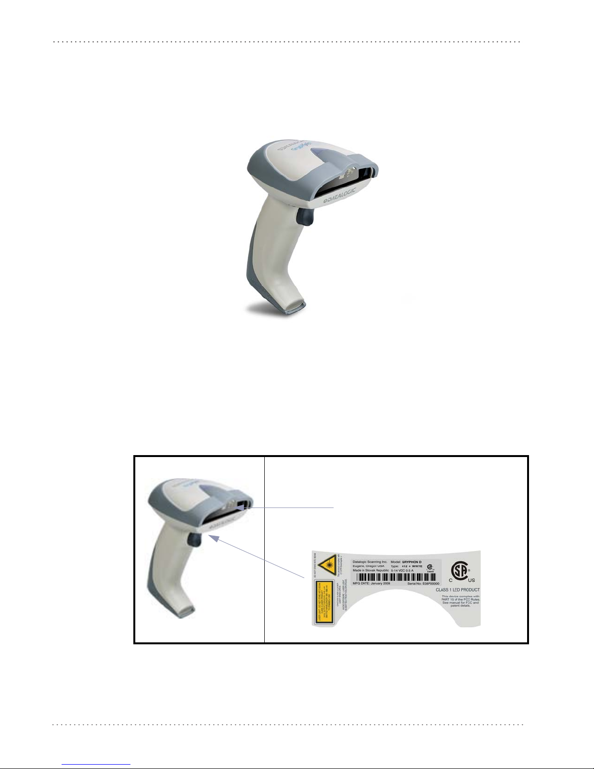
Aiming System Imager
Beam Output Window
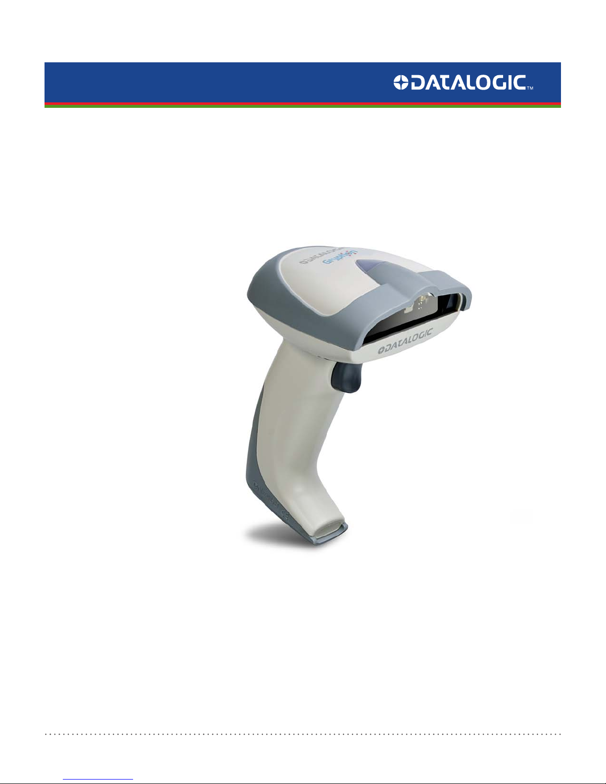
General View
Figure 1. Gryphon™ D432/D412 Plus Reader
Compliance
Figure 2
. Gryphon™ D432/D412 Plus Reader Product Labels
4 Gryphon™ D432/D412Plus
Page 7
CE Compliance
This is a Class A product. In a domestic environment this product may cause radio interference, in
which case the user may be required to take adequate measures.
WARNING
FCC Compliance
Modifications or changes to this equipment without the express written approval of Datalogic
could void the authority to use this equipment.
This device complies with Part 15 of the FCC Rules. Operation is subject to the following two
conditions: (1) This
any interference received, including interference which may cause undesired operation.
This equipment has been tested and found to comply with the limits for a Class A digital device,
pursuant to part 15 of the
protection against harmful interference when the equipment is operated in a commercial
environment. This equipment generates, uses, and can radiate radio frequency energy and, if
not installed and used in accordance with the instruction manual, may cause harmful
interference to radio communications. Operation of this equipment in a residential area is likely
to cause harmful interference in which case the user will be required to correct the interference
at his own expense.
Compliance
device may not cause harmful interference, and (2) this device must accept
FCC Rules. These limits are designed to provide reasonable
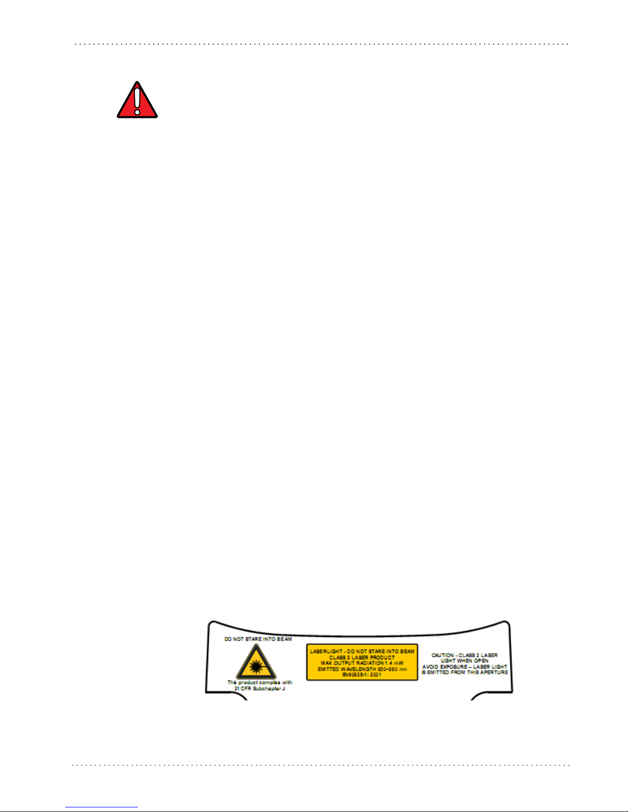
Laser Safety
The Gryphon D432/D412Plus hand-held reader is a Class 1 LED product regarding its
Illuminator and a Class 2 laser product regarding its Aiming System.
LED Illuminator
The use of an illuminator in the Gryphon D432/D412Plus Family is a Class 1 LED product:
Aiming System
The Gryphon D432/D412Plus aiming system meets the requirements for laser safety.
ILLUMINATORE LED CLASSE 1
AUSLEUCHTER LED KLASSE 1
ILLUMINATEUR A LED DE CLASSE 1
ILUMINADOR LED DE CLASE 1
Product Reference Guide 5
Page 8
Preface: About this Guide
Table 1
. Laser Safety
I D F E
LA LUCE
LASER È
VISIBILE
ALL'OCCHIO
UMANO E
VIENE
EMESSA
DALLA
FINES
TRA
INDICATA
NELLA
FIGURA.
LUCE LASER
N FIS
NO
IL FASCIO
APPARECCHI
O LASER DI
CLASSE 2
MASSIMA
POTENZA
D'USCITA:
SARE
DIE LASERSTRAH
LUNG
IST FÜR DAS
MENSCHLICH
E AUGE
SICHTBAR
UND WIRD AM
STRAHLAUSTRITTSFENTST
ER
AUSGESENDET
(SIEHE BILD)
LASERSTRAHL
UNG NIC
HT IN
DEN STRAHL
BLICKEN
PRODUKT DER
LASERKLASSE 2
MAXIMALE
AUSGANGSLEI
STUNG:
LE RAYON
ER EST
LAS
VISIBLE À
L'OEUIL NU
ET IL EST
ÉMIS PAR LA
FENÊTRE
DÉSIGNÉE
SUR
L'ILLUSTRATI
ON DANS LA
FIGURE
RAYON LASER
EVITER DE
REGARDER LE
N
RAYO
APPAREIL
LASER DE
CLASSE 2
PUISSANCE
DE SORTIE:
LA LUZ LÁSER
ES VISIBLE AL
O
OJ
HUMANO Y
ES EMITIDA
POR LA
VENTANA
INDICADA EN
LA FIGURA.
RAYO LÁSER
NO MIRAR
FIJO EL RAYO
RATO
APA
LÁSER DE
CLASE 2
MÁXIMA
POTENCIA DE
SALIDA:
WARNING
LUNGHEZZA
D'ONDA
EMESSA:
CONFORME A
EN 6082
5-1
(2001)
WELLENLÄGE:
ENTSPR. EN
6082
5-1 (2001)
LONGUER
D'ONDE
EMISE:
CONFORME A
EN 60825
-1
(2001)
LONGITUD
DE ONDA
EMITID
A:
CONFORME A
EN 6082
5-1
(2001)
ENGLISH
The following information is provided to comply with the rules imposed by international
authorities and refers to the correct use of your terminal.
STANDARD LASER SAFETY REGULATIONS
This product conforms to the applicable requirem
60825-1 at the date of manufacture.
For installation, use and maintenance, it is not necess
Use of controls or adjustments or performance of procedures other than those specified herein may
result in exposure to hazardous visible laser light.
ents of both CDRH 21 CFR 1040 and EN
to open the device.
ary
The product utilizes a low-power laser diode. Alth
momentarily causes no known biological damage, avoid staring at the beam as one would with
6 Gryphon™ D432/D412Plus
ough staring directly at the laser beam
Page 9
Compliance
any very strong light source, such as the sun. Avoid allowing the laser beam to hit the eye of an
observer, even through reflective surfaces such as mirrors, etc.
ITALIANO
Le seguenti informazioni vengono fornite dietro direttive delle autorità internazionali e si
riferiscono all’uso corretto del terminale.
NORMATIVE STANDARD PER LA SICUREZZA LASER
ATTENZIONE
Questo prodotto risulta conforme alle normative vigenti
produzione: CDRH 21 CFR 1040 e EN 60825-1.
Non si rende mai necessario aprire l’appa-recchio per
manutenzione.
L'utilizzo di procedure o regolazioni differenti da quelle d
care un'esposizione pericolosa a luce laser visibile.
Il prodotto utilizza un diodo laser a bassa potenza. Sebbene non siano noti danni riportati
dall’occhio umano in seguito ad una esposizion
così come si eviterebbe qualsiasi altra sorgente di luminosità intensa, ad esempio il sole. Evitare
inoltre di dirigere il raggio laser negli occhi di un osservatore, anche attraverso superfici
riflettenti come gli specchi.
e di breve durata, evitare di fissare il raggio laser
sulla sicurezza laser
motivi di installazione, utilizzo o
escritte nella documentazione può provo-
alla data di
DEUTSCH
Die folgenden Informationen stimmen mit den Sicherheitshinweisen überein, die von
internationalen Behörden auferlegt wurden, und sie beziehen sich auf den korrekten Gebrauch
vom Terminal.
NORM FÜR DIE LASERSICHERHEIT
ACHTUNG
Dies Produkt entspricht am Tag der Herstellung den gültige
CFR 1040 Normen für die Lasersicherheit.
Es ist nicht notwendig, das Gerät wegen Betrieb oder Installations-, und
öffnen.
Jegliche Änderungen am Gerät sowie Vorgehensweisen, die nicht in dieser Betriebsanleitung beschreiben we
Der Produkt benutzt eine Laserdiode. Obwohl zur Zeit keine Augenschäden von kurzen
Einstrahlungen bekannt sind, sollten Sie es vermeiden für längere Zeit in den Laserstrahl zu
schauen, genauso wenig wie in starke Lichtquellen (z.B. die Sonne). Vermeiden Sie es, den
Laserstrahl weder gegen die Augen eines Beobachters, noch gegen reflektierende Oberflächen zu
richten.
rden, können ein gefährliches Laserlicht verursachen.
n EN 60825-1 und CDRH 21
Wartungs-arbeiten zu
FRANÇAIS
Les informations suivantes sont fournies selon les règles fixées par les autorités internationales et
se réfèrent à une correcte utilisation du terminal.
Product Reference Guide 7
Page 10
Preface: About this Guide
NORMES DE SECURITE LASER
Ce produit est conforme aux normes de sécurité laser en vigueur à sa date de fabrication: CDRH
21 CF
R 1040 et EN 60825-1.
ATTENTION
Il n’est pas nécessaire d’ouvrir l’appareil pour l’installati
on, l’utilisation ou l’entretien.
L'utilisation de procédures ou réglages différents de ceux donnés ici peut entraîner une dangereuse
exposition à lumière laser visible.
Le produit utilise une diode laser. Aucun dommage aux yeux humains n’a été constaté à la suite
d’une exposition au rayon laser. Eviter de regarder fixement le rayon, comme toute autre source
lumineuse intense telle que le soleil. Eviter aussi de diriger le rayon vers les yeux d’un
observateur, même à travers des surfaces réfléchissantes (miroirs, par exemple).
ESPAÑOL
Las informaciones siguientes son presentadas en conformidad con las disposiciones de las
autoridades internacionales y se refieren al uso correcto del terminal.
NORMATIVAS ESTÁNDAR PARA LA SEGURIDAD LÁSER
Este aparato resulta conforme a las normativas vigentes
producción: CDRH 21 CFR 1040 y EN 60825-1.
No es necesario abrir el aparato para la instalación, la utilización o la manutención.
de seguridad láser a la fecha de
ATENCION
CAUTION
La utilización de procedimientos o regulaciones diferentes de aquellas describidas en la documentación puede causar una exposición peligrosa a la luz láser visible.
El aparato utiliza un diodo láser a baja potencia. No son notorios daños a los ojos humanos a
consecuencia de una exposición de corta duración. Eviten de mirar fijo el rayo láser así como
evitarían cualquiera otra fuente de luminosidad intensa, por ejemplo el sol. Además, eviten de
dirigir el rayo láser hacia los ojos de un observador, también a través de superficies reflectantes
como los espejos.
The Gryphon D432/D412Plus Hand-Held Reader is not user-serviceable
. Opening the case of the unit
can cause internal damage and will void the warranty.
8 Gryphon™ D432/D412Plus
Page 11

Compliance
WEEE Compliance
Waste Electrical and Electronic Equipment (WEEE) Statement
English
For information about the disposal of Waste Electrical and Electronic Equipment (WEEE),
please refer to the website at www.scanning.datalogic.com.
Italian
Per informazioni sullo smaltimento delle apparecchiature elettriche ed elettroniche consultare il
sito Web www.scanning.datalogic.com.
German
Informationen zur Entsorgung von Elektro- und Elektronik- Altgeräten (WEEE) erhalten Sie
auf der Webseite www.scanning.datalogic.com.
French
Pour toute information relative à l’élimination des déchets électroniques (WEEE), veuillez
consulter le site Internet www.scanning.datalogic.com.
Spanish
Si desea información acerca de los procedimientos para el desecho de los residuos del equipo
eléctrico y electrónico (WEEE), visite la página Web www.scanning.datalogic.com.
Portuguese
Para informações sobre a disposição de Sucatagem de Equipamentos Eléctricos e Eletrônicos
(WEEE - Waste Electrical and Electronic Equipment), consultar o site web
www.scanning.datalogic.com.
Chinese
有关处理废弃电气电子设备 (WEEE) 的信息, 请参考 Datalogic 公司的网站:
http://www.scanning.datalogic.com/。
Japanese
廃電気電子機器 (WEEE) の処理についての関連事項は Datalogic のサイト
www.scanning.datalogic.com, をご参照下さい。
Product Reference Guide 9
Page 12

Preface: About this Guide
Power Supply
This device is intended to be supplied by a UL Listed or CSA Certified Power Unit marked
"Class 2" or "LPS" output rated 5-30 V, minimum 0.75 A (Gryphon 412Plus) or 5V, 0.6 A
(Gryphon 432) which supplies power directly to the scanner via the jack connector on the
cable.
Service and Support
Datalogic provides several services as well as technical support through its website. Log on to
www.scanning.datalogic.com and click on the links indicated for further information including:
PRODUCTS
Search through the links to arrive at your product page where you can download specific
Manuals and Software & Utilities including:
• Datalogic Aladdin™, a multi-platform
SERVICE & SUPPORT
• Technical Support - Product documentation and programming guides and Technical Sup-
• Service Programs - Warranty Extensions and Maintenance Agreements
• Repair Services - Flat Rate Repairs and Return M
• Downloads – Manuals & Documentation, Data Sheets, Product Catalogues, etc.
utility program that allows device configuration
using a PC. It provides RS-232 interface configuration as well as configuration barcode
printing.
port Department in the world
aterial Authorization (RMA) Repairs.
CONTACT US
Information Request Form and Sales & Service Network
10 Gryphon™ D432/D412Plus
Page 13

Introduction
Gryphon D432/D412Plus Family Description
The Gryphon D432/D412Plus Family Hand-Held Reader packs a lot of performance into an
attractive, rugged, hand-held device. It operates in commercial and industrial environments as
well as the front office.
Chapter 1
Omni-directional
Operating
Decoding
and
Imaging
FLASH MEMORY
USA Driver License
r
sin g
Pa
Package Contents
The following parts are included in the Gryphon D432/D412Plus package contents:
• Gryphon D432/D412Plus Hand-Held Reader
• Gryphon D432/D412Plus Quick Reference Manual
To read a symbol or capture an image
D432/D412Plus Family is a powerful omni-directional reader, the orientation of the symbol is not
important.
Thanks to powerful algorithms, Gryphon D432/D412Plus reliably decodes all major 1D (linear) barcodes, 2D stacked codes (such as PDF417), 2D matrix s
POSTNET, PLANET). The data stream — acquired from decoding a symbol — is rapidly sent to the host.
The reader is immediately available to read another symbol.
Gryphon D432/D412Plus can also function as a camera
and other items.
Flash technology allows you to upgrade the Gryphon D
supported or as improved decoding algorithms become available.
The Gryphon D432/D412Plus reader can be set up to select
from USA Driver License PDF417 barcodes. This feature can be enabled using either Datalogic Aladdin™ or the barcodes in the USA Driver License Parsing Quick Reference Guide (QRG), available on
Datalogic website.
the
, you simply aim the reader and pull the trigger. Since Gryphon
y
mbols (such as DataMatrix), postal codes (such as
by capturing images of labels, signatures,
432/D412Plus reader as new symbologies are
and output a subset of data elements
You may want to save your packing material in case you need to ship the re
time.
Product Reference Guide 11
ader at some later
Page 14

Introduction
Configuration Methods
Reading Configuration Codes
This manual can be used for complete setup and configuration. If you wish to change the
default settings, you can configure the Gryphon D432/D412Plus reader by reading the
programming code symbols in this manual. Configuration commands and their relative
arguments are read individually using the symbols in this manual. See Appendix D.
Using Datalogic Aladdin™
The Datalogic Aladdin™ program, available for download from the Datalogic Web site, allows
programming the reader by selecting configuration commands or printing them through a userfriendly graphical interface running on the PC. These commands are sent to the reader over the
current communication interface, or they can be printed to be read.
Sending Configuration Strings from Host
An alternative configuration method is provided in Appendix A using the RS-232 or USB
COM interface. This method is particularly usef
with the same settings. Batch files containing the desired parameter settings can be prepared to
configure devices quickly and easily.
ul when many devices need to be configured
The Gryphon D432/D412Plus reader incorporates a
connected to a Host by plugging the correct interface cable into the connector and closing the
cable cover.
multi-standard interface, which can be
12 Gryphon™ D432/D412Plus
Page 15
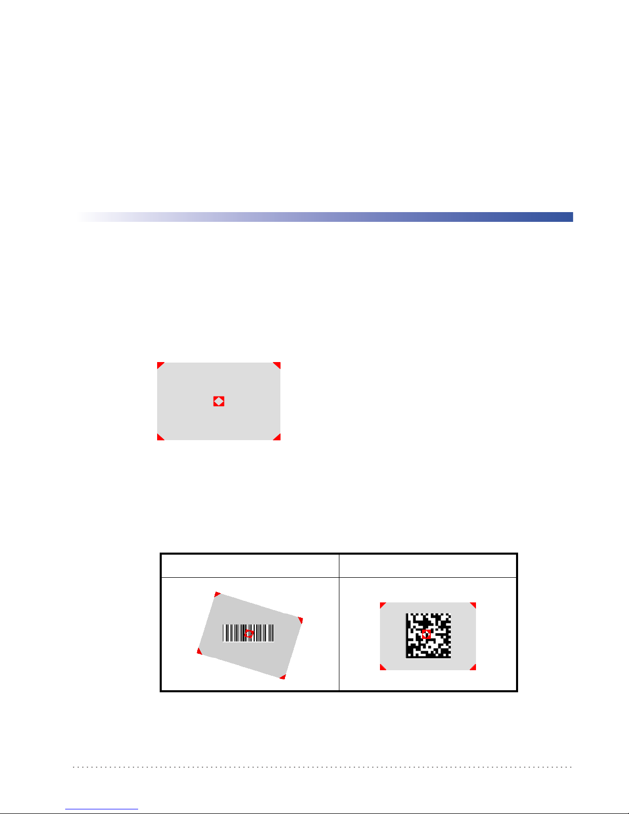
Aiming System
The Gryphon D432/D412Plus reader uses an intelligent aiming system similar to those on
cameras. By partially pulling the trigger, the aiming system indicates a field of view to be
positioned over the code:
Figure 3. Aiming System
Chapter 2
Using the Gryphon D432/412Plus
When you pull the trigger completely a red beam illuminates the code. If the aiming system is
centered and the entire symbology is within the aiming system, you will get a good read. The
field of view changes size as you move the reader closer or farther away from the code.
Figure 4
The field of view indicated by the aiming system will be smaller when the Gryphon D432/
D412Plus is closer to the code and larger when it is farther from the code. Symbologies with
smaller bars or elements (mil size) should be read closer to the unit. Symbologies with larger bars
. Relative Size and Location of Aiming System Pattern
Linear barcode 2D Matrix symbol
Product Reference Guide 13
Page 16

Using the Gryphon D432/412Plus
or elements (mil size) should be read farther from the unit. (See "Technical Features" starting on
page 119 for further details).
Normal Operation
Gryphon D432/D412Plus normally functions by capturing and decoding codes.
Point the reader at the target and pull the trigger partially to enable the aiming system. Then,
pul
l it completely to capture and decode the image. The reader will repeatedly flash until the
symbol is decoded or timeout is reached. In between the flashes of the reader, the aiming system
keeps on showing the field of view on the target (see Figure 4 on page 13
As you are reading code symbols, adjust the distance at which you are holding the reader.
The Gryphon D432/D412Plus hand-held reader aiming system is designed for general reading and decoding of 1D and 2D
symbols. Some variation in reading distance will occur due to narrow bar width and other factors.
If reading codes positioned on reflective surfaces, it may be necessary to tilt the reader with respect to the barcode.
).
14 Gryphon™ D432/D412Plus
Page 17

Image Capturing
Gryphon D432/D412Plus can also function as a camera by capturing images of labels,
signatures, and other items.
In order to capture an image, the user should read a Capture Image code (see page 80), then
point at the image subject and pull the trigger. This way, the image will be captured and sent to
the host PC. G
image you must read another Capture Image Code of the same or a different Preset
Configuration.
Normal Operation
ryphon D432/D412Plus then returns to normal operation. To capture another
You can use the aiming system to position the reader fr
centered over the target). Adjust the distance at which you are holding the reader (see Figure 4
on page 13).
If the RS-232 interface has been selected, the image will be transferred to the host PC via
XMODEM_1K protoco
Image capturing is not available in Wedge and USB Keyboard Emulation interfaces and is not compatible with Autoscanning
nor when the Software trigger type is selected.
Up to four different and independent Image Presets can be defined (see page 81).
l.
om the object (ensure the reader is about
Basic Configuration Parameters
The Image file formats supported are: TIFF, JPEG (default).
The resolution available is 752 x 480 pixels.
For JPEG images it is possible to define the Image Quality level to address tradeoff
image file size and quality.
between
Advanced Configuration Parameters
By default, for all Image Presets, the window has its original coordinates equal to zero, its width
equal to 752 pixels and its height to 480 pixels.
Brightness Adjustment is availab
Positive values shift the luminance up so that the image will result brighter. Default value is 0%,
meaning that no brightness adjustment is performed.
The same range of values (–100% up to 100%, in
Adjustment. Positive values will increase the contrast, so that dark and bright objects inside the
image will be better distinguishable. Default value is 0%, which means that no contrast
adjustment is performed.
You can set the Image Color Depth by selecting 256 gray levels (def
gray levels. Higher color depths yield larger image files. This option is ignored if the JPEG
format is selected, (256 gray levels only).
le in the range from –100% up to 100%, in steps of 1%.
steps of 1%) is available for Contrast
ault), 16 gray levels, or 2
Product Reference Guide 15
Page 18

Using the Gryphon D432/412Plus
Autoscanning
Normal Mode
Gryphon D432/D412Plus provides an autoscan command (see page 78), which when enabled,
causes the reader to scan continuously and to monitor th
way, Gryphon D432/D412Plus is ready to capture any image (containing a potential code)
positioned on a
The aiming system can be enabled to indicate the reading area of the potential code to be
captured. The
not sufficient to autodetect the potential code to be captured; furthermore, the illumination
system increases in intensity for an instant when capturing and decoding an image. A safety time
may be defined to prevent Gryphon D432/D412Plus from reading the same code repeatedly.
If the decoding is completed successfully, the reader starts monitoring the reading area again. In
case of
decoding failure, Gryphon D432/D412Plus keeps on decoding until a potential code is
present in the central zone of the reading area.
Pattern Mode
The Autoscan pattern mode is particularly advised when reading barcodes positioned on a nonuniform background. In these cases Gryphon D432/D412Plus may perceive some elements of
the background as barcodes and start the decoding. To avoid this undesired effect, the Autoscan
Pattern Code is placed in the Gryphon D432/D412Plus reading area which prevents decoding.
Using this code as the background, code reading takes place normally by presenting desired
codes to be read over the Pattern Code. Between each code read, the Pattern Code must be
presented to the reader.
illumination system can also be enabled when the ambient light conditions are
e central zone of its reading area. In this
uniform background.
The Pattern Code can be printed from this manual (see Appendix D).
In case of low ambient light conditions, Gryphon D432/D412Plus automatically activates the
illuminat
ion system. If desired, the illumination system can be enabled so that it is always active.
Defining Data Formatting
The string of a decoded code to be sent to the host may be formatted as follows:
• defining simple data formatting (see page 48);
• defining advanced data formatting giving complete flexibility in changing the format of
data (see "Advanced Data Format"on page 91).
When both simple and advanced data formatting
following order:
1. The string of the decoded code is processed acc
2. The resulting string is processed according to th
formatting;
3. Character substitution is performed on the resulting string;
4. Character deletion is performed on the
are selected the info is processed in the
ording to the advanced formatting rules;
e selection type rules of the simple data
resulting string;
5. Code concatenation is performed;
16 Gryphon™ D432/D412Plus
Page 19

6. Code ID is attached to the resulting string;
Normal Operation
7. Global headers and terminators are attach
The codes to be sent to the host may also be selected or ordered depending on the following two
conditions:
• one code per scan: Gryphon D432/D412Plus s
center. If the "Central Code Transmission" command is enabled, only the code containing
the image center will be transmitted (see page 77);
• all codes per scan: the codes to be sent to the host may be ordered either by length or by
symbology star
enabling both these criteria, codes belonging to the same symbology are sent to the host
depending on their
ting from the code being closest to the image center (see page 77). When
length.
ed to the resulting string;
ends the code being closest to the image
Concatenation
It is possible to concatenate up to 4 different codes, set their length and enable the intercode
delay between them (the intercode delay is set in the specific interface parameters. When
enabling the delay one or more global headers and terminators are added to the decoded data.
The concatenation procedure may occur in different ways depending on the number of codes to
be decoded per image.
One Code Per Scan
• If the code resulting from the single decoding of an image belongs to one of the code fam-
ilies to be concatenated, it is saved to th
other codes to complete the concatenation.
• If the code belongs to the same family of a code previously saved, it overwrites the old one.
• If the code resulting from the decoding does not belong
concatenated, it causes the concatenation failure and clears the temporary memory. If the
"Concatenation Failure Transmission" command is set to "Tx codes causing failure" (see
page 56), this code will be sent in the output message.
e Gryphon D432/D412Plus memory waiting for
to one of the code families to be
All Codes Per Scan
• All codes resulting from the decoding of an image and belonging to one of the families to
be concatenated are saved to the Gryphon D432/D412Plus memory waiting for other
codes to complete the concatenation.
• If one or more codes resulting from the decoding belong
viously saved, they overwrite the old ones.
• When the image contains no code to be concatenated,
reader temporary memory is cleared. If the "Concatenation Failure Transmission" command is set to "Tx codes causing failure" (see page 56), the codes causing the concatenation failure will be sent in the output message.
to the same family of codes pre-
the concatenation fails and the
Product Reference Guide 17
Page 20

Using the Gryphon D432/412Plus
NOTES
18 Gryphon™ D432/D412Plus
Page 21
This procedure allows setting up the reader to operate with the default settings. Whenever you
need to change the default values refer to "Changing Default Settings" on page 30.
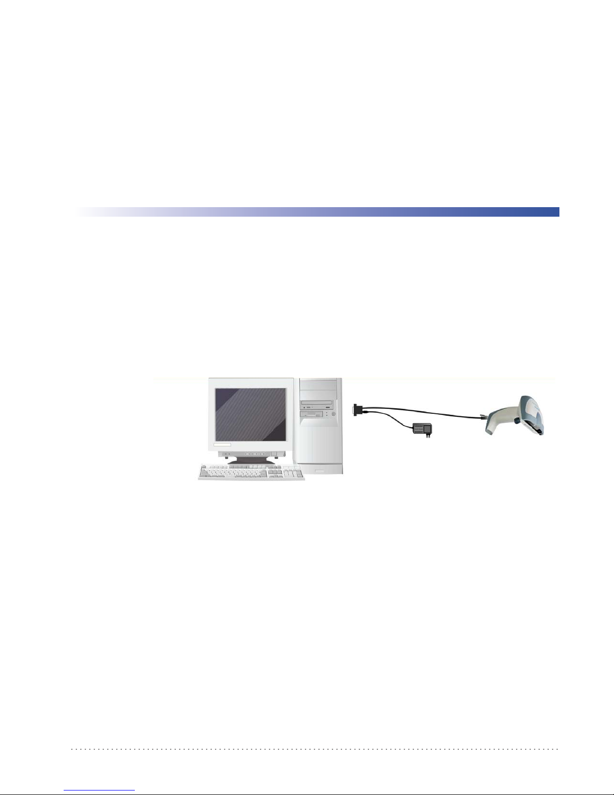
RS-232 Interface Selection
The Gryphon D432/D412Plus reader requires the RS-232 interface cable and the AC/DC
power adapter to be connected.
Chapter 3
Initial Setup
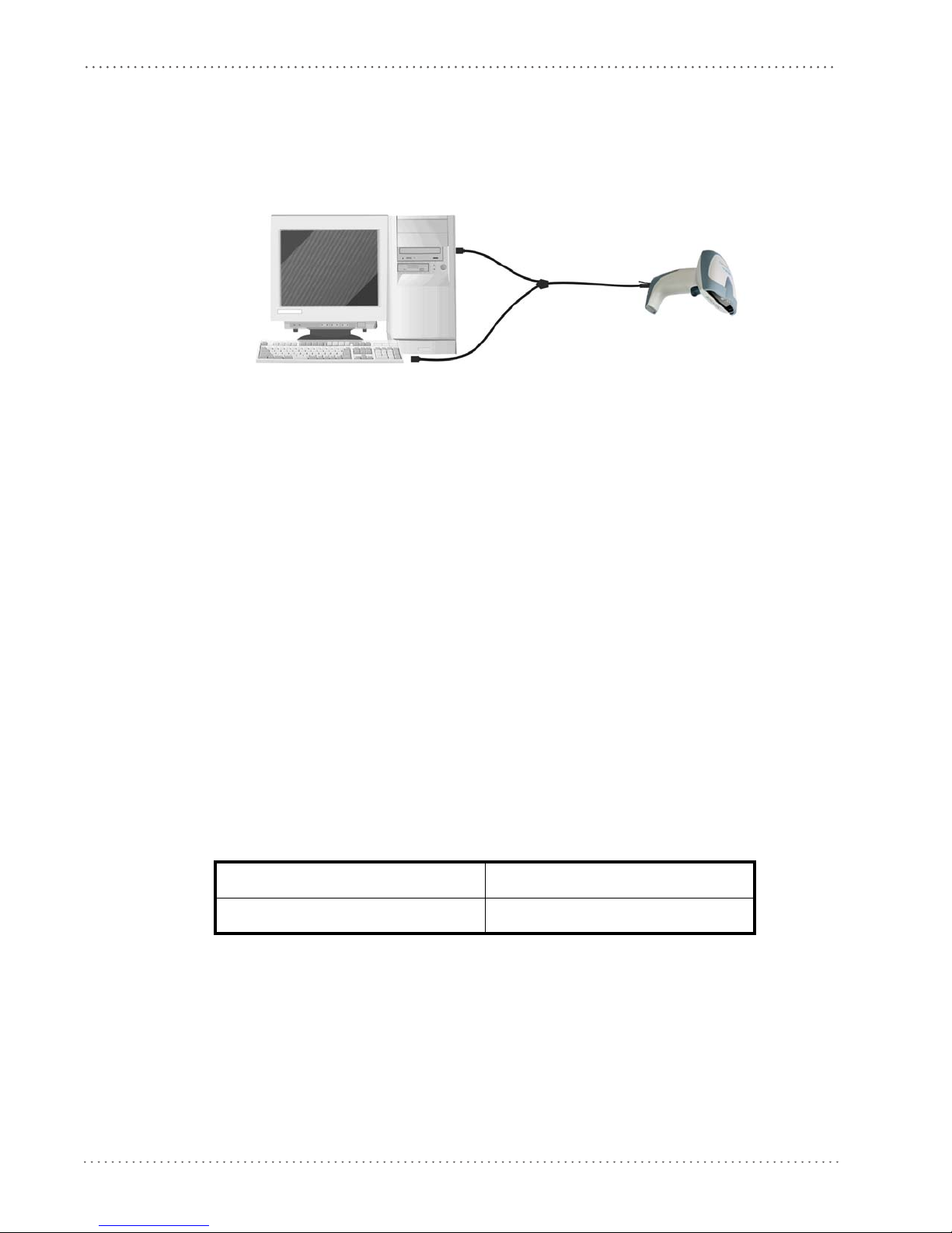
To install and configure your reader with the RS-232
1. Make all system connections as shown:
2. Read the restore default parameter code below:
Restore Default
AMHKGPAOFNGNENEIEPANHOGOCK
AHHPMBAMDKEOFMHMLJALECHGIK
AKCBPJCJGIIJCMCFGPLCMMMNLK
AEFBJLBGMHPKMOGNKKNDPDMGGK
AAPHBAJIDGHPOJKEFPNCEACBHK
AFKFBKNGLGMOMELLGOPCMJFKIK
DDDDLDLLLDDLLLLDDDLDDLDLDL
3. Read the RS-232 interface selection code:
RS-232
AMHKHMFOHNGNENEIEPANHOGOCK
AGPEPJAMDKEOFMHMLJAKFEHFKK
AMGNPJCJGIIJCMCEGJMHNDOLLK
AIFBJLBGMHPLNKECPCGMBBIBOK
AAPHBAJJDAAGMGKDDAOHBGGLHK
AEKFBONJCDDIECLFJIJKMCHLIK
DLDDLDLDLLDLLLLDLLDDDLDLLL
interface, follow these instructions:
4. Power up your PC.
RS-232 is the default interface set at the factory.
Product Reference Guide 19
Page 22
Initial Setup
Wedge Interface Selection
The Gryphon D432Plus reader requires the Wedge interface cable.
To install and configure your reader with the Wedge
1. Connect the cable to the Gryphon D432Plus re
2. Power up your PC.
3. Read the restore default parameter code below:
Restore Default
AMHKGPAOFNGNENEIEPANHOGOCK
AHHPMBAMDKEOFMHMLJALECHGIK
AKCBPJCJGIIJCMCFGPLCMMMNLK
AEFBJLBGMHPKMOGNKKNDPDMGGK
AAPHBAJIDGHPOJKEFPNCEACBHK
AFKFBKNGLGMOMELLGOPCMJFKIK
DDDDLDLLLDDLLLLDDDLDDLDLDL
4. Read the Wedge IBM AT interface selection code:
interface, follow these instructions:
ader and to the PC as shown:
USB Interface Selection
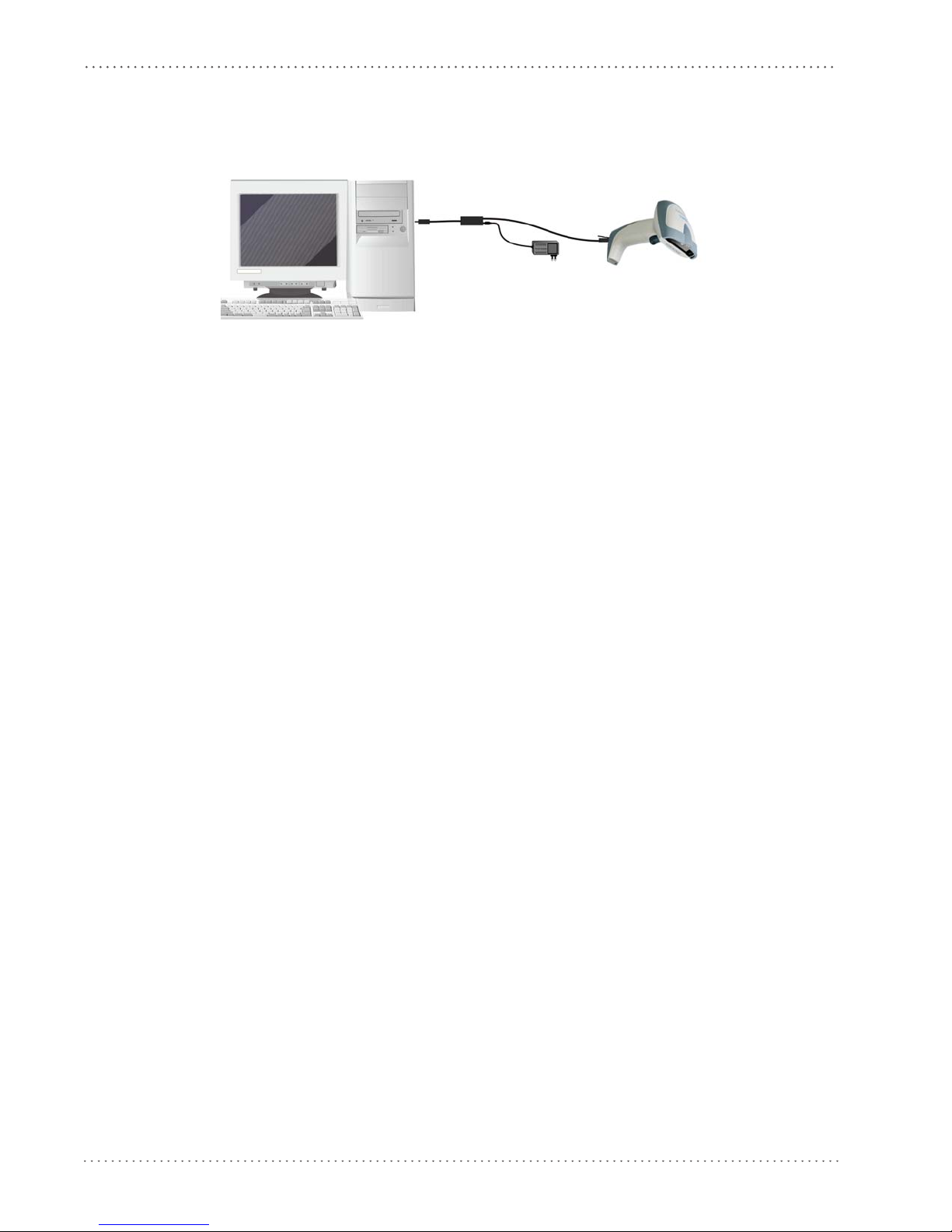
The Gryphon D432/D412Plus reader requires the USB interface cable and, if required, the
AC/DC power adapter to be connected.
The USB interface is comp
Windows 98 (and later) IBM POS for Windows
Mac OS 8.0 (and later) 4690 Operating System
Start-Up
As with all USB devices, upon connection, the Host performs several checks by communicating
with the Gryphon D432/D412Plus. During this phase the green LED on the Gryphon
D432/D412Plus reader blinks and normal operations are suspended. Two basic conditions
must be met before Gryphon D432/D412Plus is ready to read codes: the correct USB driver
must be loaded and sufficient power must be supplied to the reader.
atib
le with:
Wedge – IBM AT
AMHKHMFOHNGNENEIEPANHOGOCK
AGPEPJAMDKEOFMHMLJALFAEHKK
AEONPJCJGIIJCMCEHPLLHLPPJK
AIFBJLBGMHPLNPDFHGDGFIBDOK
AAPHBAJJCGCOPJDIMBCEANODDK
AFKFBPPJPJCAALOIKIECIPIKLK
DDLDLDLDDLDLLLLDDDDDDLDLDL
For all systems, the correct USB driver for the default USB-KBD inte
HID interface is included in the Host Operating System and will either be loaded automatically
20 Gryphon™ D432/D412Plus
rface or the USB Generic
Page 23
USB Interface Selection
box appear
power is not
sufficient?
Gree n LED o ff
Sele ct desir ed USB
interface code
(US B-KBD is defau lt)
NO
YES
R ead test codes .
Reader is READY
Load drivers
(if req uested)
Load drivers
(if req uested)
G
G
- BEEP OK
BEEP OK
Connect Gryphon™
D432/ D412Plus to Host
Disconnect reader
at Host
power supply to
cable and power up
Re co nne ct re ad er
cable to Host and
close dialog box
1.
2.
NO
YES
Read test c odes.
Reader is READY
Green LED blinks
Gree n LED o ff - BEEP OK
BEEP OK
Connect Gryphon™
D432/D412Plus to Host
Disconnect reader at Hos t
ca ble an d po wer up
Rec onnect reader cable to
Host and close dialog box
appear warning
that Bus power is
not su ffici ent?
or will be suggested by the O.S. and should therefore be selected from the dialog box (the first
time only).
If the Host supplies sufficient power to the reader,
the start-up phase ends correctly, the green
LED stops blinking and the reader emits the beep OK signal.
If the Host does not supply sufficient power to the reader, a dialog box will appear on the Host
and th
ader will be blocked (green LED continues blinking). In this case, disconnect the USB
e re
cable at the Host (green LED stops blinking), connect and power-up an external supply to USB
cable then reconnect the USB cable to the Host and close the dialog box. The reader emits the
beep OK signal. You can now read codes. At this point you can read the USB interface
configuration code according to your application. Load drivers from the O.S. (if requested).
When configuring the USB-COM interface or DLBulkUSB inter
face, the relevant files and
drivers must be installed and can be downloaded from the web site
http://www.scanning.datalogic.com.
The reader is ready.
FIRST START-UP
ree n LED blin ks
Does a dialog
war ni ng th at Bus
Successive start-ups will automatically recognize the previously loaded drivers. If external power
is used, verify that external power is already supplied.
Product Reference Guide 21
Connect external
SUCCESSIVE START-UPS
Connect ex ternal power supply to
reen LED off
Does a dialog box
Page 24
Initial Setup
To install and configure your reader with one of the USB interfaces, see the "First Start-up"
diagram above and follow these instructions.
1. Make all the Gryphon D432
/D412Plus reader connections as shown:
USB Connections
2. Power up your PC.
3. Read the desired USB interface selection code:
USB-COM EMULATION USB-KBD EMULATION
AMHKHMFOHNGNENEIEPANHOGOCK
AGPEPJAMDKEOFMHMLJALEAGEKK
AMONPJCJGIIJCMCFHLPMOOKNBK
AIFBJLBGMHPLMLAMDPIKFBLBOK
AAPHBAJICHGNBKOPLNBGLPAHFK
AHKFBNPHFKLEAOHGLPKOGDJLLK
DLDDLDLDDLDLLLLDDDLDDLDLDL
AMHKHMFOHNGNENEIEPANHOGOCK
AGPEPJAMDKEOFMHMLJAKEDBEKK
AMGNPJCJGIIJCMCFHMNJLBJPHK
AIFBJLBGMHPKNMBGMJOJEHHAOK
AAPHBAJICDHCJBCNKPCNNJNFHK
AFLFBMPJIKPAMFFBBHKCCKNIKK
DLLDLDLDLLDLLLLDDDDDDLDLLL
USB BULK USB Generic HID
AMHKHMFOHNGNENEIEPANHOGOCK
AGPEPJAMDKEOFMHMLJAKFDDHKK
AEGNPJCJGIIJCMCEHIJOCEMNPK
AIFBJLBGMHPKMICPIAFFEONCOK
AAPHBAJJCCDBHCPKNDBPGLDBBK
AHLFBOPHCJGEMAMPAAEOMGMJKK
DDDDLDLDLLDLLLLDDDLDDLDLLL
AMHKHMFOHNGNENEIEPANHOGOCK
AGPEPJAMDKEOFMHMLJALEHCGKK
AEONPJCJGIIJCMCFGKKFBJILFK
AIFBJLBGMHPKNJGBENLDAOOCOK
AAPHBAJIDFFKKOLGFOOOMCFNDK
AELFBNNJFAOIIMAMCHHKGHCJJK
DDDDLDLDDLDLLLLDLLDDDLDLDL
22 Gryphon™ D432/D412Plus
Page 25
USB Interface Selection
IBM PORT 9B/PORT 5B/IBM USB
*The IBM PORT 9B and IBM PORT 5B are only for Gryphon D412 + models.
1. Make all the Gryphon D432/D412Plus reader connections as shown:
2. Read the desired IBM interface selection codes:
IBM PORT 9B IBM PORT 5B
AMHKHMFPHMGNEJEIEPANHOGOCK
AGPFONFCPKEOFMHMLJALEABEKK
AHCPLNCJGIIJCMCEHNPGDOEBCK
AAFBJLBGMHPKMPHKHIHFLPANKK
AAPHBAJICBFFGJNMEFIBBCHBBK
AGKFBILMPCDMDEFEFKKMEDKLLK
DLDDLDLDLDLLLLLDDLDDDLDLDL
Gryphon D412 + models only
IBM USB
AMHKHMFOHNGNENEIEPANHOGOCK
AGOEPJAMDKEOFMHMLJAKECFEKK
AMONPJCJGIIJCMCFGMMHLFIFJK
AIFBJLBGMHPKMLBHKCCKPLJDOK
AAPHBAJIDDFDDLPAENDNINCJHK
AHKFBNJDHPIEOENLMJAAEBAIJK
DDDDLDLDLLLLLLLDDLLDDLDLLL
AMHKHMFPHMGNEJEIEPANHOGOCK
AGPFONEDPKEOFMHMLJAKEFFHKK
AHCPLNCJGIIJCMCEHMLILIKJGK
AAFBJLBGMHPLNIFNPNEPPFMNKK
AAPHBAJJCCAFHGAJDDKJMHFFFK
AELFBINACDBGBBGHDPBAIMCLLK
DDDDLDLDDDLLLLLDLLLDDLDLDL
Product Reference Guide 23
Page 26

Initial Setup
NOTES
24 Gryphon™ D432/D412Plus
Page 27

Chapter 4
Configuration Using Code Symbols
This section describes the programming method of using configuration code symbols to
program your reader. By using the Gryphon D432/D412Plus reader to read/decode these
special configuration symbols, you can configure, and obtain information from its system
software.
When you are reading configuration code symbols,
2D reader to avoid reading adjacent symbols.
The configuration code symbols in this chapter are divided into logical sections according to the
type
of configuration required, (RS-232 configuration, Code selection, etc.). If arguments are
required with a command, you can read additional code labels (typically digits) from
Appendix D.
USA Driver License Parsing is a feature not covered in this manual. For more information, reference the “USA Driver License Parsing
Quick Reference Guide”, available on the Datalogic website at www.scanning.datalogic.com.
To configure your reader:
1. Read the Enter Configuration code ONC
2. Modify the desired parameters in one or more sections by reading the parameter code and
lecting the value from the Hex/Numeric table (see Appendix D) or
se
given procedures.
3. Read the Exit and Save Configuration code ONCE, av
Example for step 3
carefully aim the Gryphon D432/D412Plus
E, available on top of each page.
by following the
ailable on top of each page.
To set the maximum length of characters in a Code 39 barcode symbol that the reader will
decode t
o 32:
• first read the Maximum Length symbol for Code 39 on page 61
• then read the symbol for the digit "3" and lastly the symbol for the digit "2" in
Appendix D.
Product Reference Guide 25
Page 28

Configuration Using Code Symbols
Default Settings
Configuration Field Default Setting
RS-232 Communication
Baud Rate 115200
Parity, Data Bits, Stop Bits No parity; 8 Data bits; 1 Stop bit
Handshake None
ACK/NACK Protocol None
FIFO Enabled
Intercharacter Delay 0
Intercode Delay 0
RX Timeout 10 seconds
Serial Trigger Lock Disabled
Serial Trigger Lock Disable Character NUL
Serial Trigger Lock Enable Character NUL
USB COM Emulation
Handshake None
ACK/NACK Protocol None
FIFO Enabled
Intercharacter Delay 0
Intercode Delay 0
RX Timeout 10 seconds
USB Keyboard Emulation
FIFO Enabled
Intercharacter Delay 0
Intercode Delay 0
*Keyboard Nationality USA
*Keyboard Speed Normal
WEDGE-Communication
*Keyboard Nationality USA
CapsLock OFF
CapsLock Auto-Recognition ON
NumLock OFF
Intercharacter Delay 0
Intercode Delay 0
IBM 46xx Interface DEFAULT SETTINGS
protocol= Port 5B 1520, format = IBM Standard Format
IBM USB Interface DEFAULT SETTINGS
device usage Handheld
* The default values of these parameters are set when reading the interface selection.
26 Gryphon™ D432/D412Plus
Page 29

Configuration Field Default Setting
Data Format-Symbology Independent Parameters
Code Identifier Disabled
Custom Code Identifier Disabled
Code Length Disabled
*Header No headers
CR and LF terminators for RS-232, USB BULK, USB COM, USB
neric HID
*Terminator
Data Format-Symbology Dependent Parameters
Symbology Specific Format Select All
Header Symbology No headers
Terminator Symbology No terminators
Symbology Character Substitution No character to substitute
Symbology Character Deletion No character to delete
Data Format-Concatenation
Concatenation Disabled
Define Concatenation 2 EAN/UPC codes concatenated
Set First Concatenated Code Length 000 = any length
Set Second Concatenated Code Length 000 = any length
Set Third Concatenated Code Length 000 = any length
Set Fourth Concatenated Code Length 000 = any length
Concatenation with Intercode Delay Disabled
Concatenation Timeout 10 seconds
Concatenation Failure Transmission Tx codes causing failure
Transmission after Timeout No code transmission
Concatenation Result Code ID No code Identifier
Ge
ENTER terminator for Wedge, USB Kbd
Default Settings
Advanced Formatting
Format enable/disable Disabled
Camera Control
Exposure Mode Automatic, based on entire image
Power Save
Illumination Power Max power
Illumination System Power ON
Code Selection
Issue Identical Codes Enabled
EAN/UPC
Selection Enabled
Add-On Disabled
UPCE Expansion Disabled
Code 39
Selection Enabled - no check digit
Code 39 Full ASCII
Disabled
Product Reference Guide 27
Page 30

Configuration Using Code Symbols
Configuration Field Default Setting
Code Length Check Disabled
Minimum Length 001
Maximum Length 255
Start/Stop Character Disabled
Code 32
Selection Disabled
Interleaved 2 of 5
Selection Disabled
Code Length Check Disabled
Minimum Length 014
Maximum Length 255
Codabar
Selection Disabled
Code Length Check Disabled
Minimum Length 001
Maximum Length 255
Code 128
Code128 Selection Enabled
Code Length Check Disabled
Minimum Length 001
Maximum Length 255
EAN 128
Selection Disabled
Code Length Check Disabled
Minimum Length 001
Maximum Length 255
Code 93
Selection Disabled
Code Length Check Disabled
Minimum Length 001
Maximum Length 255
PDF417
Selection Enabled
Option Macro PDF417 Buffered Mode
Micro PDF417 Disabled
GS1 DataBar™ Family
GS1 DataBar Expanded Disabled
GS1 DataBar Limited Disabled
GS1 DataBar Omnidirectional Disabled
GS1 DataBar Expanded Stacked Disabled
GS1 DataBar Stacked
28 Gryphon™ D432/D412Plus
Disabled
Page 31

Configuration Field Default Setting
Data Matrix
Selection Enabled - normal & inverted
Rectangular Style Enabled
Minimum Code Length 0001
Maximum Code Length 3600
QR
Selection Enabled
Postal Codes
Selection Disabled
Australian Table
Selection N Table
Maxicode
Maxicode Mode 0 Disabled
Maxicode Mode 1 Disabled
Maxicode Mode 2 Disabled
Maxicode Mode 3 Disabled
Maxicode Mode 4 Disabled
Maxicode Mode 5 Disabled
Maxicode Mode 6 Disabled
Aztec
Selection Disabled
Default Settings
Composite Codes
Selection Disabled
Discard Linear Part Enabled
Reading Parameters
Trigger Mode Trigger level
Trigger Type Normal trigger
Flash ON 2 sec
Flash OFF 2 sec
Beeper Tone Tone 1
Beeper Volume High volume
Beeper Duration 50 ms
Reads per Cycle One read per cycle
Aiming System Delay Disabled
Good Read Spot Disabled
Scan Timeout 5 sec
User Defined Beeper Tone Ton e 1
User Defined Beeper Volume High Volume
User Defined Beeper Duration 100 ms
Codes per Scan One code per scan
Central Code Transmission Disabled
Order by Code Length
Disabled
Product Reference Guide 29
Page 32

Configuration Using Code Symbols
Configuration Field Default Setting
Order by Code Symbology Disabled
Autoscan Mode Disabled
Autoscan Aiming System Enabled
Autoscan Hardware Trigger Enabled
Autoscan Illumination System Disabled
Safety Time
Stand AutoScan Mode Normal
Image Formatting
Image Preset 1, 2, 3, 4
Image Format JPEG format
Set JPEG Quality Factor 50
Brightness 0%
Cont rast 0%
Color Depth
Changing Default Settings
500 ms (if Autoscan mode or Soft
ware trigger type is
selected and the Multiple Reads per Cycle option is enabled.
256 gray levels
Once the reader is set up, you can change the default parameters to meet your application needs.
Refer to the preceding paragraphs for initial configuration in order to set the default values and
select the interface for your application.
In this manual the configuration parameters are divided into logical groups, making it easy to
find the desired function base in its reference group.
The RS-232, USB, WEDGE grou
The following parameter groups are common to all
• DA
• PO
• C
TA FORMAT parameters regard the messages sent to the Host system.
WER SAVE parameters manage overall current consumption in the device.
ODE SELECTION parameters allow configuration of a personalized mix of codes,
ps are for Standard Interface parameter configuration.
interface applications:
code families and their options.
• RE
ADING PARAMETERS control various operating modes and indicators status func-
tioning.
• CAPTURE IMA
• AD
• AD
VANCED CAPTURE IMAGE parameters define options of the image to capture.
VANCED DATA FORMAT parameters allow advanced formatting of messages
GE parameters activate image capturing.
towards the Host.
Once the configuration is modified, it is possible
to save it as a Custom Default Configuration
and to restore it at any time using a specific command.
SAVE CUSTOM DEFAULT RESTORE CUSTOM DEFAULT
AMHKGOBOFNGNENEIEPANHOGOCK
AHHPMJAMDKEOFMHMLJALEBDGIK
AKCBPJCJGIIJCMCFHOOBOFKHJK
AEFBJLBGMHPLMLBENPIJOBOEGK
AAPHBAJICAELBENPOIFJGNJBHK
AGKFBJKCGEBMMAEBJHEAKDILKK
DDDDLDLLLLDLLLLDLDLDDLDLLL
30 Gryphon™ D432/D412Plus
AMHKGOBOFNGNENEIEPANHOGOCK
AHHPMBIMDKEOFMHMLJALEHBFIK
AKCBPJCJGIIJCMCFGPNNEKBJPK
AEFBJLBGMHPLMMGACKPFEHFFGK
AAPHBAJIDDAMENHAAFBFAFPDBK
AHKFBMLLKCCKGKAEDCDMCKPKIK
DDDDLDLLLLDLLLLDDDLDDLDLLL
Page 33

\
Enter Reader Configuration Exit and Save Reader Configuration
AMHKGMHOFNGNENEIEPANHOGOCK
AHPNIBAMDKEOFMHMLJALFCAFIK
AKCBPJCJGIIJCMCEGOODCCEDJK
AEFBJLBGMHPLNPGLABJHFIAEGK
AAPHBAJICCBGBIAFNLNLLAINDK
AFLFBPPCOIHKILNFFOCKOLJILK
DLDDLDDLDDLLLLLDDDLDDLDLLL
RS-232 INTERFACE
AMHKCMHOFNGNENEIEPANHOGOCK
AHPNIBAMDKEOFMHMLJALFEGFIK
AKCBPJCJGIIJCMCEGLJKNEBJLK
AEFBJLBGMHPLMIFPAFAIIBNHGK
AAPHBAJIDGDHOJDKAICECIENBK
AGLFBOMJMHLIGBPCKIGAGOEKLK
DDLDLDDLLLDLLLLDDDDDDLDLDL
RS-232 INTERFACE
BAUD RATE
1200 baud 2400 baud
AODOBPHMHNGNENEIEPANHOGOCK
AHHPMBIMDKEOFMHMLJALEAEHIK
AKCBPJCJGIIJCMCFGKKJKOJDJK
AEFBJLBGMHPLMKBDIAOJAOCFGK
AAPHBAJJDEBGGOGPJMMKGENDBK
AGKFAMOCFGFEOEMPKONGEDGLJK
DDDLLLLDDLLLLLLDLDLDDLDLDL
4800 baud 9600 baud
AODOBPHMHNGNENEIEPANHOGOCK
AHHPEJIMDKEOFMHMLJALFBDEIK
AKCBPJCJGIIJCMCEGJKDEHBFLK
AEFBJLBGMHPLMOFOMLCDNGPGGK
AAPHBAJICAGAPEPJLLEPPMPNFK
AGLFAOPPDHDGCAJLOLBOAEPJJK
DDLLLLLDDLLLLLLDDDDDDLDLLL
AODOBPHMHNGNENEIEPANHOGOCK
AHHPMBAMDKEOFMHMLJAKFFEFIK
AKCBPJCJGIIJCMCEHMOCCMGBNK
AEFBJLBGMHPKNKGHFCHBECLHGK
AAPHBAJICAFOGLINMDNLINCNFK
AFKFAPIBAPGEIJIHHJLGAGJLIK
DDDLLLLDDLLLLLLDDDLDDLDLDL
AODOBPHMHNGNENEIEPANHOGOCK
AHHPEJAMDKEOFMHMLJAKEEDGIK
AKCBPJCJGIIJCMCFHPOIMFOHPK
AEFBJLBGMHPKNOCKBJLLJKGEGK
AAPHBAJJDECIPBBLOEFOBFADBK
AFLFANJMGOAGENNDDMHOEBAJIK
DDLLLLLDDLLLLLLDLDDDDLDLLL
14400 baud 19200 baud
AODOBPHMHNGNENEIEPANHOGOCK
AHHPEBIMDKEOFMHMLJAKECBFIK
AKCBPJCJGIIJCMCFGONEGKFJJK
AEFBJLBGMHPKNJFOOMMHDMNFGK
AAPHBAJJCHGPKILEAJBCHNGBHK
AELFAIIFKIDAOHJGJJACMIHIKK
DDLLLLLDDLLLLLLDDDDDDLDLLL
AODOBPHMHNGNENEIEPANHOGOCK
AHHPEBAMDKEOFMHMLJALFHBHIK
AKCBPJCJGIIJCMCEHIJPOIKLNK
AEFBJLBGMHPLMJCKDOFPHAEHGK
AAPHBAJIDDCHKNFGFGADJEJPDK
AHLFALOGPBAAIKNOEOGCINIILK
DDLLLLLDDLLLLLLDLDDDDLDLLL
38400 baud 57600 baud
AODOBPGMHNGNENEIEPANHOGOCK
AHHPMJIMDKEOFMHMLJAKEGAGIK
AKCBPJCJGIIJCMCEHJMNMHBHNK
AEFBJLBGMHPLMJEFHPOOLLEGGK
AAPHBAJJDEELFPOLNABGHGBJBK
AHKFAPKHDDAKGGJMLDOCGOJIJK
DLLLLLLDLLDLLLLDDLDDDLDLLL
AODOBPGMHNGNENEIEPANHOGOCK
AHHPMJAMDKEOFMHMLJALFDAEIK
AKCBPJCJGIIJCMCFGPIGEFOFJK
AEFBJLBGMHPKNJDBKNHGPHNEGK
AAPHBAJICAADFKAJIPAHJPOHFK
AEKFAMMEGKDKALNEGEICCLGIIK
DLLLLLLDLLDLLLLDLLDDDLDLLL
115200 baud
AODOBPGMHNGNENEIEPANHOGOCK
AHHPMBIMDKEOFMHMLJALFFCHIK
AKCBPJCJGIIJCMCFHOLKOKFLPK
AEFBJLBGMHPKNOEFFIAKFBGFGK
AAPHBAJIDDEEADKGGCELPHIFDK
AFKFAJNNKMAMKBJBMBPOKCBJKK
DLLLLLLDLLDLLLLDDLDDDLDLLL
Product Reference Guide 31
Page 34

Enter Reader Configuration Exit and Save Reader Configuration
AMHKGMHOFNGNENEIEPANHOGOCK
AHPNIBAMDKEOFMHMLJALFCAFIK
AKCBPJCJGIIJCMCEGOODCCEDJK
AEFBJLBGMHPLNPGLABJHFIAEGK
AAPHBAJICCBGBIAFNLNLLAINDK
AFLFBPPCOIHKILNFFOCKOLJILK
DLDDLDDLDDLLLLLDDDLDDLDLLL
RS-232 INTERFACE
AMHKCMHOFNGNENEIEPANHOGOCK
AHPNIBAMDKEOFMHMLJALFEGFIK
AKCBPJCJGIIJCMCEGLJKNEBJLK
AEFBJLBGMHPLMIFPAFAIIBNHGK
AAPHBAJIDGDHOJDKAICECIENBK
AGLFBOMJMHLIGBPCKIGAGOEKLK
DDLDLDDLLLDLLLLDDDDDDLDLDL
PARITY
None Odd
AODOCKHMHNGNENEIEPANHOGOCK
AHHPMJAMDKEOFMHMLJAKEHDEIK
AKCBPJCJGIIJCMCFHKNICLPJPK
AEFBJLBGMHPKMKCBGHIFAIHGGK
AAPHBAJICBECCPIFDALHLEPDBK
AHKFAKNLOFKOENMPPBAEMFGLKK
DLLLLLLDDDLLLLLDDLLDDLDLDL
Even
AODOCKHMHNGNENEIEPANHOGOCK
AHHPMBAMDKEOFMHMLJALFEBFIK
AKCBPJCJGIIJCMCEHNKPAGLFNK
AEFBJLBGMHPLNNCBEAGBOCFFGK
AAPHBAJJCGENHDMIICOKDFGPDK
AFKFAMKBHKKIIKMCIDBIAJOKJK
DLLLLLLDDDLLLLLDDLLDDLDLDL
AODOCKHMHNGNENEIEPANHOGOCK
AHHPMBIMDKEOFMHMLJAKEBBHIK
AKCBPJCJGIIJCMCFGLOEIEEHJK
AEFBJLBGMHPKMNFFJCPJKOMHGK
AAPHBAJIDCAFHGCKNNPLNMJBHK
AGKFAPMCCDJIOHIKFEHIEMBKIK
DLLLLLLDDDLLLLLDLLLDDLDLDL
DATA BITS
7 Bits 8 Bits
AODKGOHMHNGNENEIEPANHOGOCK
AHHPMJAMDKEOFMHMLJALFGHFIK
AKCBPJCJGIIJCMCEHMNLNAOLPK
AEFBJLBGMHPLNNCDILOHNKLGGK
AAPHBAJICBAGNCCMNKDBECODFK
AFKFAMPJFJLIGJIGMPLCONMJKK
DLLLLLLDDDDLLLLDDLLDDLDLLL
AODKGOHMHNGNENEIEPANHOGOCK
AHHPMBIMDKEOFMHMLJALFAFGIK
AKCBPJCJGIIJCMCEGNOHHPFFJK
AEFBJLBGMHPLNKFHHOJLHMAHGK
AAPHBAJIDCEBILIDDHHNCKIBDK
AEKFAJOAJPIOMDMDGKMOGELIIK
DLLLLLLDDDDLLLLDLLLDDLDLLL
STOP BITS
1 Bit 2 Bits
AODKGOHMFNGNENEIEPANHOGOCK
AHHPMJAMDKEOFMHMLJALEDHFIK
AKCBPJCJGIIJCMCFGPJNAPDJLK
AEFBJLBGMHPLNPBLKBBJJBCEGK
AAPHBAJIDBEGBLCBDNBOCGFFDK
AEKFAMNDDBAAALDFGLGGCILLKK
DDLLLLLDLLDLLLLDLLDDDLDLLL
AODKGOHMFNGNENEIEPANHOGOCK
AHHPMBIMDKEOFMHMLJALEFFGIK
AKCBPJCJGIIJCMCFHOKBKAIHNK
AEFBJLBGMHPLNIGPFEGFDHJFGK
AAPHBAJICCABECIONAFCEODHFK
AFKFAJMKPHDGKBHAMOBKKBMKIK
DDLLLLLDLLDLLLLDDLDDDLDLLL
ACK/NACK PROTOCOL
Disabled Enabled
AODKGKHMFNGNENEIEPANHOGOCK
AHHPMJAMDKEOFMHMLJAKEBBHIK
AKCBPJCJGIIJCMCEGIPKHBNLJK
AEFBJLBGMHPLNPGMAAHBOHIFGK
AAPHBAJJDEDMBEFCELBBMOPPDK
AFLFAIPIECJKKHKLNFCCILOKJK
DDDLLLLDDLLLLLLDDDDDDLDLDL
AODKGKHMFNGNENEIEPANHOGOCK
AHHPMBIMDKEOFMHMLJAKEHDEIK
AKCBPJCJGIIJCMCEHJMGNOGFPK
AEFBJLBGMHPLNIBIPFANEBDEGK
AAPHBAJJCHHLENPNKGFNKGJNFK
AELFANOBIEKMANOOHAFOACJLLK
DDDLLLLDDLLLLLLDLDDDDLDLDL
32 Gryphon™ D432/D412Plus
See "ACK/NACK Protocol" on page 113 for details.
Page 35

\
Enter Reader Configuration Exit and Save Reader Configuration
AMHKGMHOFNGNENEIEPANHOGOCK
AHPNIBAMDKEOFMHMLJALFCAFIK
AKCBPJCJGIIJCMCEGOODCCEDJK
AEFBJLBGMHPLNPGLABJHFIAEGK
AAPHBAJICCBGBIAFNLNLLAINDK
AFLFBPPCOIHKILNFFOCKOLJILK
DLDDLDDLDDLLLLLDDDLDDLDLLL
RS-232 INTERFACE
AMHKCMHOFNGNENEIEPANHOGOCK
AHPNIBAMDKEOFMHMLJALFEGFIK
AKCBPJCJGIIJCMCEGLJKNEBJLK
AEFBJLBGMHPLMIFPAFAIIBNHGK
AAPHBAJIDGDHOJDKAICECIENBK
AGLFBOMJMHLIGBPCKIGAGOEKLK
DDLDLDDLLLDLLLLDDDDDDLDLDL
RX TIMEOUT
RX Timeout
AODKBPHMFNGNENEIEPANHOGOCK
AHPNIJAMDKEOFMHMLJALFFCFIK
AKCBPJCJGIIJCMCEGJNHKMOHPK
AEFBJLBGMHPLMOFHAGONLNCEGK
AAPHBAJJDFAAALCKIJIBHMDDFK
AFKFAMNLMCOCGLMJDCDIENPLKK
DLLLLLLDLLDLLLLDLDDDDLDLLL
Read a number in the range
00-99, where:
00= disabled
01-99= timeout from 1 to 99
secs
See "RX Timeout" on page 113 for details.
SERIAL TRIGGER LOCK
Disabled Enabled
AODPCOHMHNGNENEIEPANHOGOCK
AHHPMJAMDKEOFMHMLJALEHCEIK
AKCBPJCJGIIJCMCEGPPNPFEFLK
AEFBJLBGMHPLNIHIDCFKGICHGK
AAPHBAJICFBGACOMKGOJHNKLFK
AEKFANPJPMFEGKBGFLJOMIIIIK
DLLLDLLDLDDLLLLDDDDDDLDLLL
AODPCOHMHNGNENEIEPANHOGOCK
AHHPMBIMDKEOFMHMLJALEBAHIK
AKCBPJCJGIIJCMCEHOMBFKPLNK
AEFBJLBGMHPLNPAMMHCGMOJGGK
AAPHBAJIDGFBFLEDELKFBFMJDK
AFKFAIOADKGCMAFDPOOCEBPJKK
DLLLDLLDLDDLLLLDLDDDDLDLLL
Serial Trigger Lock Characters
AODPBPHMFNGNENEIEPANHOGOCK
AHPNIJAMDKEOFMHMLJALECBEIK
AKCBPJCJGIIJCMCEHPIIHPBDJK
AEFBJLBGMHPLNMDILLMPNGGGGK
AAPHBAJJCFDBCKNFCGKGNLLLHK
AHKFAMOAEIMMICHOFAFOONGIIK
DDDLDLLDLDLLLLLDLLDDDLDLDL
None XON/XOFF
AODKGKHMHNGNENEIEPANHOGOCK
AHHPMJAMDKEOFMHMLJAKFEBHIK
AKCBPJCJGIIJCMCFHLLMKOAJNK
AEFBJLBGMHPLNNFECKIPKMBHGK
AAPHBAJJCEHMNNFPKMDOKKEJFK
AELFAINCCKCCMFBIHBPGEOJIJK
DLDLLLLDLDLLLLLDLDLDDLDLDL
RTS/CTS RTS Always On
AODKGKHMHNGNENEIEPANHOGOCK
AHHPMBAMDKEOFMHMLJALEHDGIK
AKCBPJCJGIIJCMCEHMMLIDEFPK
AEFBJLBGMHPKMKFEANGLEGDEGK
AAPHBAJICDHDIBBCBOGDCLNFHK
AGLFAOKILFCEACBFADOKICBJKK
DLDLLLLDLDLLLLLDLDLDDLDLDL
Read two characters for Serial Trigger Lock/
Unlock.
The 2 characters must be read sequentially as
Hex values from the Hex/Numeric table.
Valid values are in the range 00-FF
H
ANDSHAKE
AODKGKHMHNGNENEIEPANHOGOCK
AHHPMBIMDKEOFMHMLJAKFCDEIK
AKCBPJCJGIIJCMCFGKIAABLHLK
AEFBJLBGMHPLNKCANPPDAKKGGK
AAPHBAJJDHDLIEPAEBHCMCCLDK
AFLFANMLOMBEGPFNNEIKMHOJLK
DLDLLLLDLDLLLLLDDDLDDLDLDL
AODKGKHMHNGNENEIEPANHOGOCK
AHHPEJIMDKEOFMHMLJAKEDEHIK
AKCBPJCJGIIJCMCEGJIKOIDBJK
AEFBJLBGMHPLNOGNJEDJNCHFGK
AAPHBAJICDENBOGGGGPHFKAFHK
AFKFAPNGINHGKLAJJBECIAHLLK
DLLLLLLDLDLLLLLDLDDDDLDLLL
Product Reference Guide 33
Page 36

Enter Reader Configuration Exit and Save Reader Configuration
AMHKGMHOFNGNENEIEPANHOGOCK
AHPNIBAMDKEOFMHMLJALFCAFIK
AKCBPJCJGIIJCMCEGOODCCEDJK
AEFBJLBGMHPLNPGLABJHFIAEGK
AAPHBAJICCBGBIAFNLNLLAINDK
AFLFBPPCOIHKILNFFOCKOLJILK
DLDDLDDLDDLLLLLDDDLDDLDLLL
RS-232 INTERFACE
AMHKCMHOFNGNENEIEPANHOGOCK
AHPNIBAMDKEOFMHMLJALFEGFIK
AKCBPJCJGIIJCMCEGLJKNEBJLK
AEFBJLBGMHPLMIFPAFAIIBNHGK
AAPHBAJIDGDHOJDKAICECIENBK
AGLFBOMJMHLIGBPCKIGAGOEKLK
DDLDLDDLLLDLLLLDDDDDDLDLDL
FIFO
Disabled Enabled
AODKGKFOHNGNENEIEPANHOGOCK
AHHPMJAMDKEOFMHMLJALEHEEIK
AKCBPJCJGIIJCMCFHKPBPDILLK
AEFBJLBGMHPLMKFOFBKAHDNHGK
AAPHBAJJDDHLEHJBMCFNGJDNHK
AGKFAILCKNMOEJCKPGAMODCKIK
DLDLLLLDLLDLLLLDLDDDDLDLLL
AODKGKFOHNGNENEIEPANHOGOCK
AHHPMBIMDKEOFMHMLJALEBGHIK
AKCBPJCJGIIJCMCFGLMNFMDFNK
AEFBJLBGMHPLMNCKKENMNFGGGK
AAPHBAJJCADMBODOCPBBABFPBK
AHKFANKLGLPIODGPFDHAGKFLKK
DLDLLLLDLLDLLLLDDDDDDLDLLL
INTERCHARACTER DELAY
Intercharacter Delay
AODKBPHMHNGNENEIEPANHOGOCK
AHPNIJAMDKEOFMHMLJALEACFIK
AKCBPJCJGIIJCMCFHKJBHDDFLK
AEFBJLBGMHPLMMGPCMBDPGLGGK
AAPHBAJJCFEAMCCHGOKOBIIFDK
AEKFAMPBKKFKAJHKJGOMIIIJKK
DDLLLLLDDDDLLLLDDDLDDLDLLL
00
01-99
= disabled
= delay from 1 to 99
msec
Intercode Delay
AODKBPFOHNGNENEIEPANHOGOCK
AHPNIJAMDKEOFMHMLJAKFDHGIK
AKCBPJCJGIIJCMCFHLNMCOLHNK
AEFBJLBGMHPLNLGFFHDMCJHGGK
AAPHBAJJDCEHFIOJAAMNNLPBBK
AGLFAMJBCNLGIFEIBBBGCFDLLK
DDLLLLLDDLLLLLLDDDDDDLDLDL
INTERCODE DELAY
00
01-99
= disabled
= delay from 1 to 99
sec
34 Gryphon™ D432/D412Plus
Page 37

\
Enter Reader Configuration Exit and Save Reader Configuration
AMHKGMHOFNGNENEIEPANHOGOCK
AHPNIBAMDKEOFMHMLJALFCAFIK
AKCBPJCJGIIJCMCEGOODCCEDJK
AEFBJLBGMHPLNPGLABJHFIAEGK
AAPHBAJICCBGBIAFNLNLLAINDK
AFLFBPPCOIHKILNFFOCKOLJILK
DLDDLDDLDDLLLLLDDDLDDLDLLL
USB
AMHKCMHOFNGNENEIEPANHOGOCK
AHPNIBAMDKEOFMHMLJALFEGFIK
AKCBPJCJGIIJCMCEGLJKNEBJLK
AEFBJLBGMHPLMIFPAFAIIBNHGK
AAPHBAJIDGDHOJDKAICECIENBK
AGLFBOMJMHLIGBPCKIGAGOEKLK
DDLDLDDLLLDLLLLDDDDDDLDLDL
USB
USB COM Emulation
HANDSHAKE
None XON/XOFF
AOALGKHMHNGNENEIEPANHOGOCK
AHHPMJAMDKEOFMHMLJALFDBFIK
AKCBPJCJGIIJCMCEHONJKCAFPK
AEFBJLBGMHPKMMEGABIEOIJGGK
AAPHBAJICGEOOFKLJMHMGMPDFK
AGLFAJIKEDPOKPPMNLCCCFGIJK
DLLLLLLDDLDLLLLDDDLDDLDLLL
AOALGKHMHNGNENEIEPANHOGOCK
AHHPMBIMDKEOFMHMLJALFFDGIK
AKCBPJCJGIIJCMCEGPOFANLLJK
AEFBJLBGMHPKMLDCPEPIEOCHGK
AAPHBAJIDFAJLMAEHBDAAEJBDK
AHLFAMJDIFMIAFLJHOFOKMBJLK
DLLLLLLDDLDLLLLDLDLDDLDLLL
RTS/CTS
AOALGKHMHNGNENEIEPANHOGOCK
AHHPMBAMDKEOFMHMLJAKEADEIK
AKCBPJCJGIIJCMCFHJKOIPEJNK
AEFBJLBGMHPLNLEGCGGAACLFGK
AAPHBAJJCBEBLJOGCOCBONGPHK
AELFAPPANMPIGIPBKJDOOJOJKK
DLLLLLLDDLDLLLLDDDLDDLDLLL
ACK/NACK PROTOCOL
Disabled Enabled
AOALGKHMFNGNENEIEPANHOGOCK
AHHPMJAMDKEOFMHMLJALEGBFIK
AKCBPJCJGIIJCMCFGNJPHNNHLK
AEFBJLBGMHPKMOHOCLHKKDAEGK
AAPHBAJIDGAOCMKGHLFDAIEFDK
AHLFAJKACLEGMNEPHPPGOABKJK
DDLLLLLDLDDLLLLDLDDDDLDLLL
AOALGKHMFNGNENEIEPANHOGOCK
AHHPMBIMDKEOFMHMLJALEADGIK
AKCBPJCJGIIJCMCFHMKDNCGJNK
AEFBJLBGMHPKMJAKNOAGAFLFGK
AAPHBAJICFEJHFAJJGBPGACHFK
AGLFAMLJONHAGHAKNKIKGJGLLK
DDLLLLLDLDDLLLLDDDDDDLDLLL
See "ACK/NACK Protocol" on page 113 for details.
FIFO
Disabled Enabled
AOALGKFOHNGNENEIEPANHOGOCK
AHHPMJAMDKEOFMHMLJAKEAEGIK
AKCBPJCJGIIJCMCEHPJEPPIHJK
AEFBJLBGMHPKNLEMHKKLDHFGGK
AAPHBAJIDBEJHPGFPCBPKPIHHK
AEKFAJOKMEBCCDMOFMNIIINKIK
DLLLLLLDDDLLLLLDDDDDDLDLDL
AOALGKFOHNGNENEIEPANHOGOCK
AHHPMBIMDKEOFMHMLJAKEGGFIK
AKCBPJCJGIIJCMCEGOKIFADJPK
AEFBJLBGMHPKNMDIIPNHJBOHGK
AAPHBAJICCAOCGMKBPFDMHOFBK
AFKFAMPDACCEIJILPJKEABKLKK
DLLLLLLDDDLLLLLDLDDDDLDLDL
Product Reference Guide 35
Intercharacter Delay
AOALBPHMHNGNENEIEPANHOGOCK
AHPNIJAMDKEOFMHMLJAKEHCHIK
AKCBPJCJGIIJCMCEHPPEHPDJJK
AEFBJLBGMHPKNNHNAHBILCDHGK
AAPHBAJICHHCPKNDFOOMNODPDK
AGKFANKJMDIGGDJODMDIODHJKK
DDDLLLLDLLLLLLLDLDLDDLDLDL
I
NTERCHARACTER DELAY
00
01-99
= disabled
= delay from 1 to 99
msec
Page 38

Enter Reader Configuration Exit and Save Reader Configuration
AMHKGMHOFNGNENEIEPANHOGOCK
AHPNIBAMDKEOFMHMLJALFCAFIK
AKCBPJCJGIIJCMCEGOODCCEDJK
AEFBJLBGMHPLNPGLABJHFIAEGK
AAPHBAJICCBGBIAFNLNLLAINDK
AFLFBPPCOIHKILNFFOCKOLJILK
DLDDLDDLDDLLLLLDDDLDDLDLLL
USB
AMHKCMHOFNGNENEIEPANHOGOCK
AHPNIBAMDKEOFMHMLJALFEGFIK
AKCBPJCJGIIJCMCEGLJKNEBJLK
AEFBJLBGMHPLMIFPAFAIIBNHGK
AAPHBAJIDGDHOJDKAICECIENBK
AGLFBOMJMHLIGBPCKIGAGOEKLK
DDLDLDDLLLDLLLLDDDDDDLDLDL
INTERCODE DELAY
Intercode Delay
AOALBPFOHNGNENEIEPANHOGOCK
AHPNIJAMDKEOFMHMLJALFEHEIK
AKCBPJCJGIIJCMCEHOLJCCLLPK
AEFBJLBGMHPKMKHHHMDHGNPHGK
AAPHBAJIDAHFGABNDAIPBNELBK
AELFANMJEEGKOPKMLLMCEOMLLK
DDDLLLLDLDDLLLLDLDDDDLDLLL
00
01-99
= disabled
= delay from 1 to 99
sec
RX TIMEOUT
RX Timeout
AODKBPHMFNGNENEIEPANHOGOCK
AHPNIJAMDKEOFMHMLJALFFCFIK
AKCBPJCJGIIJCMCEGJNHKMOHPK
AEFBJLBGMHPLMOFHAGONLNCEGK
AAPHBAJJDFAAALCKIJIBHMDDFK
AFKFAMNLMCOCGLMJDCDIENPLKK
DLLLLLLDLLDLLLLDLDDDDLDLLL
Read a number in the range
00-99, where:
00= disabled
01-99= timeout from 1 to 99
secs
See "RX Timeout" on page 113 for details.
36 Gryphon™ D432/D412Plus
Page 39

\
Enter Reader Configuration Exit and Save Reader Configuration
AMHKGMHOFNGNENEIEPANHOGOCK
AHPNIBAMDKEOFMHMLJALFCAFIK
AKCBPJCJGIIJCMCEGOODCCEDJK
AEFBJLBGMHPLNPGLABJHFIAEGK
AAPHBAJICCBGBIAFNLNLLAINDK
AFLFBPPCOIHKILNFFOCKOLJILK
DLDDLDDLDDLLLLLDDDLDDLDLLL
USB
AMHKCMHOFNGNENEIEPANHOGOCK
AHPNIBAMDKEOFMHMLJALFEGFIK
AKCBPJCJGIIJCMCEGLJKNEBJLK
AEFBJLBGMHPLMIFPAFAIIBNHGK
AAPHBAJIDGDHOJDKAICECIENBK
AGLFBOMJMHLIGBPCKIGAGOEKLK
DDLDLDDLLLDLLLLDDDDDDLDLDL
USB Keyboard Emulation
FIFO
Disabled Enabled
AOAPGKFOHNGNENEIEPANHOGOCK
AHHPMJAMDKEOFMHMLJALECDEIK
AKCBPJCJGIIJCMCEHJJOKGPNLK
AEFBJLBGMHPLMPBJKCBJCCEFGK
AAPHBAJICBGIEIKMBJAMEMFDFK
AHLFAJLKDIKCEOHGFFIACHKIKK
DDDLLDLDDDLLLLLDLDDDDLDLLL
Intercharacter Delay
AOAPFLHMFNGNENEIEPANHOGOCK
AHPNIJAMDKEOFMHMLJAKFEFHIK
AKCBPJCJGIIJCMCEGIKGHBCJPK
AEFBJLBGMHPLNMFDFAKDEDMEGK
AAPHBAJJDGEIPKFLPHCACJDHFK
AGKFAIMDALNGCKCMNJLKKPPKLK
DLLLLDLDDLLLLLLDDLLDDLDLLL
INTERCHARACTER DELAY
00
01-99
AOAPGKFOHNGNENEIEPANHOGOCK
AHHPMBIMDKEOFMHMLJALEEBHIK
AKCBPJCJGIIJCMCEGIKCAJEDNK
AEFBJLBGMHPLMIGNFHGFIEPEGK
AAPHBAJIDCCPBBADPEEACEDBDK
AGLFAMKDPOJEOEDDPAPMKONJIK
DDDLLDLDDDLLLLLDDDDDDLDLLL
= disabled
= delay from 1 to 99
msec
Intercode Delay
AOAPFLHMHNGNENEIEPANHOGOCK
AHPNIJAMDKEOFMHMLJAKEBFHIK
AKCBPJCJGIIJCMCFHLOAKOPLLK
AEFBJLBGMHPLNOGLHKFNAIFGGK
AAPHBAJJCGAIDDFGBAAPENIBDK
AHKFAIOJGDGOEIJPHNGOGKIILK
DDLLLDLDLDLLLLLDLLDDDLDLLL
INTERCODE DELAY
00
01-99
= disabled
= delay from 1 to 99
sec
Product Reference Guide 37
Page 40

Enter Reader Configuration Exit and Save Reader Configuration
AMHKGMHOFNGNENEIEPANHOGOCK
AHPNIBAMDKEOFMHMLJALFCAFIK
AKCBPJCJGIIJCMCEGOODCCEDJK
AEFBJLBGMHPLNPGLABJHFIAEGK
AAPHBAJICCBGBIAFNLNLLAINDK
AFLFBPPCOIHKILNFFOCKOLJILK
DLDDLDDLDDLLLLLDDDLDDLDLLL
USB
AMHKCMHOFNGNENEIEPANHOGOCK
AHPNIBAMDKEOFMHMLJALFEGFIK
AKCBPJCJGIIJCMCEGLJKNEBJLK
AEFBJLBGMHPLMIFPAFAIIBNHGK
AAPHBAJIDGDHOJDKAICECIENBK
AGLFBOMJMHLIGBPCKIGAGOEKLK
DDLDLDDLLLDLLLLDDDDDDLDLDL
KEYBOARD NATIONALITY
This parameter default value is restored through the Interface Selection code and not Restore
Default.
Belgian English
AOAPCOGMHNGNENEIEPANHOGOCK
AHHPMJIMDKEOFMHMLJAKFFAHIK
AKCBPJCJGIIJCMCEHIJFLFPNPK
AEFBJLBGMHPLMLHCHGLKEBCFGK
AAPHBAJJDECOEEAFHDAPIFOFDK
AHLFAKJGEAHOKMOLCCDMAIBLKK
DDLLLDLDLDLLLLLDDDLDDLDLLL
French German
AOAPCOHMHNGNENEIEPANHOGOCK
AHHPMBAMDKEOFMHMLJAKEGEEIK
AKCBPJCJGIIJCMCEHNLKFOILPK
AEFBJLBGMHPKNIFAFLCFLINEGK
AAPHBAJICADLHAGDGAMCHONBHK
AFLFAKLAHMBAEDPAOIGIGABILK
DLDLLDLDDDDLLLLDDLDDDLDLDL
AOAPCOHMHNGNENEIEPANHOGOCK
AHHPEJAMDKEOFMHMLJAKFHDHIK
AKCBPJCJGIIJCMCFHOLALHANNK
AEFBJLBGMHPKNMBNBAOPGAAHGK
AAPHBAJJDEENOKPFEHEHOGPPDK
AFKFAIKNBNHCIHKEKNKACHIKLK
DLLLLDLDDDDLLLLDLLLDDLDLLL
AOAPCOHMHNGNENEIEPANHOGOCK
AHHPEJIMDKEOFMHMLJALECDFIK
AKCBPJCJGIIJCMCEGIPLDFPPJK
AEFBJLBGMHPLMMGJMCHHCMJFGK
AAPHBAJICAAFOPBHBIFGAPABHK
AGKFALMOEEECOKOMHKMAGCHKKK
DLLLLDLDDDDLLLLDDLLDDLDLLL
Italian Japanese
AOAPCOHMHNGNENEIEPANHOGOCK
AHHPMBIMDKEOFMHMLJALFDEGIK
AKCBPJCJGIIJCMCFGLPBNMHJLK
AEFBJLBGMHPLMICEIJLNPEEGGK
AAPHBAJJDEHDHFIBDPNDJHCPDK
AGLFAJNDCFCACOLIDPAICFOIKK
DLDLLDLDDDDLLLLDLLDDDLDLDL
AOAPCOGMHNGNENEIEPANHOGOCK
AHHPMJAMDKEOFMHMLJALEAAFIK
AKCBPJCJGIIJCMCFGONODHAPLK
AEFBJLBGMHPKNLAGKECCANLHGK
AAPHBAJICAGGEBOHCMBOGMBLHK
AELFAJPFBJEOMBKDPFFMENOLLK
DDLLLDLDLDLLLLLDLDLDDLDLLL
Spanish Swedish
AOAPCOHMHNGNENEIEPANHOGOCK
AHHPEBAMDKEOFMHMLJALEEBGIK
AKCBPJCJGIIJCMCEHJMHJKEBPK
AEFBJLBGMHPLMLBNDHALIKCEGK
AAPHBAJIDDECLGLIPFBKGHGDBK
AHKFAONHICHEEAKJNPLMOLALIK
DLLLLDLDDDDLLLLDLLLDDLDLLL
AOAPCOHMHNGNENEIEPANHOGOCK
AHHPEBIMDKEOFMHMLJAKFBBEIK
AKCBPJCJGIIJCMCFGPIMBILDLK
AEFBJLBGMHPKNLGJOFJDMGLGGK
AAPHBAJJCHAKLDFKKKALIOJNFK
AEKFANLENLEECNOBAINMKOPLJK
DLLLLDLDDDDLLLLDDLLDDLDLLL
USA
AOAPCOHMHNGNENEIEPANHOGOCK
AHHPMJAMDKEOFMHMLJALFFGFIK
AKCBPJCJGIIJCMCFHKMNHDMHNK
AEFBJLBGMHPLMPFAHMMBFCPHGK
AAPHBAJJCHDECMCONCJPPPENFK
AHLFAMMKODBGIEPNJKHEKMJJIK
DLDLLDLDDDDLLLLDDLDDDLDLDL
38 Gryphon™ D432/D412Plus
Page 41

\
Enter Reader Configuration Exit and Save Reader Configuration
AMHKGMHOFNGNENEIEPANHOGOCK
AHPNIBAMDKEOFMHMLJALFCAFIK
AKCBPJCJGIIJCMCEGOODCCEDJK
AEFBJLBGMHPLNPGLABJHFIAEGK
AAPHBAJICCBGBIAFNLNLLAINDK
AFLFBPPCOIHKILNFFOCKOLJILK
DLDDLDDLDDLLLLLDDDLDDLDLLL
USB
AMHKCMHOFNGNENEIEPANHOGOCK
AHPNIBAMDKEOFMHMLJALFEGFIK
AKCBPJCJGIIJCMCEGLJKNEBJLK
AEFBJLBGMHPLMIFPAFAIIBNHGK
AAPHBAJIDGDHOJDKAICECIENBK
AGLFBOMJMHLIGBPCKIGAGOEKLK
DDLDLDDLLLDLLLLDDDDDDLDLDL
KEYBOARD SPEED
This parameter default value is restored through the Interface Selection code and not Restore
Default.
Normal Fas t
AOAPBPGMFNGNENEIEPANHOGOCK
AHHPEJIMDKEOFMHMLJALEBGHIK
AKCBPJCJGIIJCMCEGJIEPKNDJK
AEFBJLBGMHPLNNDGIDBCOOAEGK
AAPHBAJJDEHOFMOFDGMGKIAJFK
AFLFAJNANAPEGCNKPFNGOKFKLK
DDDLLDLDLDDLLLLDLDLDDLDLLL
AOAPBPHMFNGNENEIEPANHOGOCK
AHHPMBAMDKEOFMHMLJAKFAHGIK
AKCBPJCJGIIJCMCEGINGNFGPJK
AEFBJLBGMHPLNNFJMCKDCFAFGK
AAPHBAJIDDBCKOFILANDEKIPHK
AFKFANJBBCPOIOJIAIFGAJEKJK
DLDLLDLDDDLLLLLDDLLDDLDLLL
After setting the Keyboard Speed, it is necessary to disconnect and reconnect the USB cable to the PC.
See "Keyboard Speed" on page 113
for details.
Product Reference Guide 39
Page 42

Enter Reader Configuration Exit and Save Reader Configuration
AMHKGMHOFNGNENEIEPANHOGOCK
AHPNIBAMDKEOFMHMLJALFCAFIK
AKCBPJCJGIIJCMCEGOODCCEDJK
AEFBJLBGMHPLNPGLABJHFIAEGK
AAPHBAJICCBGBIAFNLNLLAINDK
AFLFBPPCOIHKILNFFOCKOLJILK
DLDDLDDLDDLLLLLDDDLDDLDLLL
USB
AMHKCMHOFNGNENEIEPANHOGOCK
AHPNIBAMDKEOFMHMLJALFEGFIK
AKCBPJCJGIIJCMCEGLJKNEBJLK
AEFBJLBGMHPLMIFPAFAIIBNHGK
AAPHBAJIDGDHOJDKAICECIENBK
AGLFBOMJMHLIGBPCKIGAGOEKLK
DDLDLDDLLLDLLLLDDDDDDLDLDL
USB IBM
Ta bl e Top HandHeld
IBM 46XX
PROTOCOL
Port 9B (4501) Port 5B (1520)
FORMAT
Code 39 Mixed
40 Gryphon™ D432/D412Plus
IBM Standard
Page 43

\
Enter Reader Configuration Exit and Save Reader Configuration
AMHKGMHOFNGNENEIEPANHOGOCK
AHPNIBAMDKEOFMHMLJALFCAFIK
AKCBPJCJGIIJCMCEGOODCCEDJK
AEFBJLBGMHPLNPGLABJHFIAEGK
AAPHBAJICCBGBIAFNLNLLAINDK
AFLFBPPCOIHKILNFFOCKOLJILK
DLDDLDDLDDLLLLLDDDLDDLDLLL
WEDGE INTERFACE
AMHKCMHOFNGNENEIEPANHOGOCK
AHPNIBAMDKEOFMHMLJALFEGFIK
AKCBPJCJGIIJCMCEGLJKNEBJLK
AEFBJLBGMHPLMIFPAFAIIBNHGK
AAPHBAJIDGDHOJDKAICECIENBK
AGLFBOMJMHLIGBPCKIGAGOEKLK
DDLDLDDLLLDLLLLDDDDDDLDLDL
WEDGE INTERFACE
CAPS LOCK
Caps Lock Off Caps Lock On
AOCOCOFOHNGNENEIEPANHOGOCK
AHHPMJAMDKEOFMHMLJAKEEHFIK
AKCBPJCJGIIJCMCFHPJMFONJPK
AEFBJLBGMHPKMPEAEFKPFEBEGK
AAPHBAJJDDHLCANDMPHCNCFDHK
AFLFALKFFFDCEGMMLKJKOLEKJK
DDLLLLLDLLDLLLLDLDLDDLDLDL
CAPS LOCK AUTO-RECOGNITION
Disabled Enabled
AOCKGOFOBNGNENEIEPANHOGOCK
AHHPMJAMDKEOFMHMLJALEHHGIK
AKCBPJCJGIIJCMCFGMIHHEGDPK
AEFBJLBGMHPKMNCOEGANBCAEGK
AAPHBAJICGHHLLJCDOLBAPHHBK
AGKFANMKJEKEKLMFDFKAEEPJIK
DLDLLLLDDDDLLLLDDLDDDLDLDL
AOCOCOFOHNGNENEIEPANHOGOCK
AHHPMBIMDKEOFMHMLJAKECFGIK
AKCBPJCJGIIJCMCFGOKAPBGHJK
AEFBJLBGMHPKMIDELANDPCKFGK
AAPHBAJJCADMHJHMCCDOLKDBBK
AELFAOLMJDAEOMIJBPOGGCDLLK
DDLLLLLDLLDLLLLDDDLDDLDLDL
AOCKGOFOBNGNENEIEPANHOGOCK
AHHPMBIMDKEOFMHMLJALEBFFIK
AKCBPJCJGIIJCMCFHNLLNLNNJK
AEFBJLBGMHPKMKFKLDHBLELFGK
AAPHBAJIDFDAOCDNNDPNGHBFHK
AHKFAINDFCJCABIAJANMMNIIKK
DLDLLLLDDDDLLLLDLLDDDLDLDL
Caps lock manual configuration is ignored when Caps Lock Auto-Recognition
is enabled.
NUM LOCK
Num Lock Off Num Lock On
AOCOCOFOFNGNENEIEPANHOGOCK
AHHPMJAMDKEOFMHMLJAKFBHFIK
AKCBPJCJGIIJCMCEGMNKIBALLK
AEFBJLBGMHPKMNHIGPFBBPIGGK
AAPHBAJJCDDLOJNOCIFNLGOFBK
AELFALIPDNIKCEHPBOEOCODIJK
DLLLLLLDDDDLLLLDDDDDDLDLDL
AOCOCOFOFNGNENEIEPANHOGOCK
AHHPMBIMDKEOFMHMLJAKFHFGIK
AKCBPJCJGIIJCMCEHNOGCOLFNK
AEFBJLBGMHPKMKAMJKCNLJDHGK
AAPHBAJJDAHMLAHBMFBBNOIHHK
AFLFAOJGPLLMIODKLLDCKHEJLK
DLLLLLLDDDDLLLLDLDDDDLDLDL
INTERCHARACTER DELAY
Intercharacter Delay
AOCKFPFODNGNENEIEPANHOGOCK
AHPNIJAMDKEOFMHMLJALECEGIK
AKCBPJCJGIIJCMCFHMPCPODFNK
AEFBJLBGMHPKMJGOMPJIKMEFGK
AAPHBAJJCGFAJDKLLOPOKJGHDK
AFKFAMNDCADMEDKNDOGAGBBJIK
DDLLLLLDDDLLLLLDLDDDDLDLLL
00
01-99
= disabled
= delay from 1 to 99
msec
INTERCODE DELAY
Product Reference Guide 41
Intercode Delay
AOCKFPHMDNGNENEIEPANHOGOCK
AHPNIJAMDKEOFMHMLJAKFBBFIK
AKCBPJCJGIIJCMCFHNLPKDLHLK
AEFBJLBGMHPKNOGELELHHDIFGK
AAPHBAJJDBFHAJGFNAJNGKBDBK
AHLFAMLDKHNAMPJPLJJKMMKLJK
DDLLLLLDDLDLLLLDLDLDDLDLDL
00
01-99
= disabled
= delay from 1 to 99
sec
Page 44

Enter Reader Configuration Exit and Save Reader Configuration
AMHKGMHOFNGNENEIEPANHOGOCK
AHPNIBAMDKEOFMHMLJALFCAFIK
AKCBPJCJGIIJCMCEGOODCCEDJK
AEFBJLBGMHPLNPGLABJHFIAEGK
AAPHBAJICCBGBIAFNLNLLAINDK
AFLFBPPCOIHKILNFFOCKOLJILK
DLDDLDDLDDLLLLLDDDLDDLDLLL
WEDGE INTERFACE
AMHKCMHOFNGNENEIEPANHOGOCK
AHPNIBAMDKEOFMHMLJALFEGFIK
AKCBPJCJGIIJCMCEGLJKNEBJLK
AEFBJLBGMHPLMIFPAFAIIBNHGK
AAPHBAJIDGDHOJDKAICECIENBK
AGLFBOMJMHLIGBPCKIGAGOEKLK
DDLDLDDLLLDLLLLDDDDDDLDLDL
KEYBOARD NATIONALITY
This parameter default value is restored through the Interface Selection code and not Restore
Default.
Belgian English
AOCOCOGMHNGNENEIEPANHOGOCK
AHHPMJIMDKEOFMHMLJAKFHEEIK
AKCBPJCJGIIJCMCEHMIJMFGBLK
AEFBJLBGMHPKNMGIDEPLJIAGGK
AAPHBAJJDHGGNCDGAAIBGLIPDK
AHKFANJJHBLGOCOIIFCIOCHKKK
DLDLLLLDDDDLLLLDLLLDDLDLDL
French German
AOCOCOHMHNGNENEIEPANHOGOCK
AHHPMBAMDKEOFMHMLJAKEEAHIK
AKCBPJCJGIIJCMCEHJKGCOBHLK
AEFBJLBGMHPLMPEKBJGEGBPHGK
AAPHBAJICDHDOGFABDEMJALLHK
AFKFANLPENNIANPDEPHMIKHJLK
DDLLLLLDLDLLLLLDLDDDDLDLLL
AOCOCOHMHNGNENEIEPANHOGOCK
AHHPEJAMDKEOFMHMLJAKFFHEIK
AKCBPJCJGIIJCMCFHKKMMHJBJK
AEFBJLBGMHPLMLAHFCKOLJCEGK
AAPHBAJJDHAFHMMGDEMJAIJFDK
AFLFAPKCCMLKMJKHAKLEMNOLLK
DDDLLLLDLDLLLLLDDDLDDLDLDL
AOCOCOHMHNGNENEIEPANHOGOCK
AHHPEJIMDKEOFMHMLJALEAHGIK
AKCBPJCJGIIJCMCEGMOHEFGDNK
AEFBJLBGMHPKNLHDIADGPFLGGK
AAPHBAJICDENHJCEGLNIOBGLHK
AGLFAMMBHFIKKEOPNNNEIIBLKK
DDDLLLLDLDLLLLLDLDLDDLDLDL
Italian Japanese
AOCOCOHMHNGNENEIEPANHOGOCK
AHHPMBIMDKEOFMHMLJALFBAFIK
AKCBPJCJGIIJCMCFGPONKMOFPK
AEFBJLBGMHPKNPDOMLPMCNGFGK
AAPHBAJJDHDLODLCEMFNHJEFDK
AGKFAONMBEOIGALLJIBMMPIJKK
DDLLLLLDLDLLLLLDDDDDDLDLLL
AOCOCOGMHNGNENEIEPANHOGOCK
AHHPMJAMDKEOFMHMLJALECEGIK
AKCBPJCJGIIJCMCFGKMCEHJDPK
AEFBJLBGMHPLMMBMOGGDNEJEGK
AAPHBAJICDCONHNEFPJAICHBHK
AEKFAOPKCIIGIPKAFCEIKHIKLK
DLDLLLLDDDDLLLLDDLLDDLDLDL
Spanish Swedish
AOCOCOHMHNGNENEIEPANHOGOCK
AHHPEBAMDKEOFMHMLJALEGFFIK
AKCBPJCJGIIJCMCEHNNLOKNNLK
AEFBJLBGMHPKNMAHHFEKFDAHGK
AAPHBAJIDAAKCAILIGJEIJAJBK
AHLFAJNILDLMAOKKHIKIABGKIK
DDDLLLLDLDLLLLLDDDLDDLDLDL
AOCOCOHMHNGNENEIEPANHOGOCK
AHHPEBIMDKEOFMHMLJAKFDFHIK
AKCBPJCJGIIJCMCFGLJAGICPPK
AEFBJLBGMHPLMMHDKHNCBPJFGK
AAPHBAJJCEECCFGJNJIFGAPHFK
AELFAKLLOKIMGDOCKPMIEEJKJK
DDDLLLLDLDLLLLLDLDLDDLDLDL
USA
AOCOCOHMHNGNENEIEPANHOGOCK
AHHPMJAMDKEOFMHMLJALFHCGIK
AKCBPJCJGIIJCMCFHONBADFLJK
AEFBJLBGMHPKNIEKDOIAILNEGK
AAPHBAJJCEHMLKBNKBBBBBCHFK
AHKFALMFNCNOMKPODNGAEGPIIK
DDLLLLLDLDLLLLLDLDDDDLDLLL
42 Gryphon™ D432/D412Plus
Page 45

Default Settings
KEYBOARD SETTING
The values set by this procedure are not effected by the Restore Default code but will be lost if
the Interface Selection code is read.
Set Alphanumeric Keys
AOCOBLHMHNGNENEIEPANHOGOCK
AHPNIJAMDKEOFMHMLJAKEFHEIK
AKCBPJCJGIIJCMCFHKIFCIDNNK
AEFBJLBGMHPKNOEFDMIDAIKGGK
AAPHBAJJDBGBFEFKLAHODLCLBK
AELFAONNHNGEOMLLCMDAAFDLLK
DDLLLLLDLLLLLLLDDDLDDLDLLL
The reader can be used with terminals or PCs with various key
board types and nationalities
through a simple keyboard setting procedure.
Keyboard setting consists of communicating to t
he reader how to send data corresponding to
the keyboard used in the application. The keys must be set in a specific order.
Press and release a key to set it.
Some characters may require more than one key pressed simultaneously during
normal use
(refer to the manual of your PC or terminal for keyboard use). The exact sequence must be
indicated to the reader in this case pressing and releasing the different keys.
Example
If one has to press the "Shift" and "4" keys simultaneous
ly on the keyboard to transmit the
character "$" to the video, to set the "$", press and release "Shift" then press and release "4".
Each pressed and released key must generate an acoustic signal on the reader, otherwise repress
the key
. Never press more than one key at the same time, even if this corresponds to the normal
use of your keyboard.
Press "Backspace" to correct a wrong key entry. In th
is case the reader emits a wrong beep.
"CAPS LOCK" and "NUM LOCK" must be off before starting the keyboard setting procedure. "SHIFT" must be repressed for each character and cannot be
substituted by "CAPS LOCK".
1. Read the "Set Alphanumeric Keys" code.
2. Press the keys shown in Table 2 on page 44, according to their numerical order.
Some ASCII characters may be missing as this de
pends on the type of keyboard: these are
generally particular characters relative to the various national symbologies. In this case:
• The first 4 characters (Shift, Alt, Ctrl, and B
ackspace) can only be substituted with
keys not used, or substituted with each other.
• Characters can be substituted with other single symbols (e.g. "SP
ACE") even if not
included in the barcode set used.
• Characters can be substituted with others corr
esponding to your keyboard.
The reader signals the end of the procedure with 3 beeps indicating the keys
ha
ve been registered.
Product Reference Guide 43
Page 46

Configuration Using Code Symbols
Tabl e 2
. Alphanumeric Keys
01 : Shift
02 : Alt
03 : Ctrl
04 : Backspace
05 : SPACE 28 : 7 51 : N
06 : ! 29 : 8 52 : O
07 : " 30 : 9 53 : P
08 : # 31 : : 54 : Q
09 : $ 32 : ; 55 : R
10 : % 33 : < 56 : S
11 : & 34 : = 57 : T
12 : ' 35 : > 58 : U
13 : ( 36 : ? 59 : V
14 : ) 37 : @ 60 : W
15 : * 38 : A 61 : X
16 : + 39 : B 62 : Y
17 : , 40 : C 63 : Z
18 : - 41 : D 64 : [
19 : . 42 : E 65 : \
20 : / 43 : F 66 : ]
21 : 0 44 : G 67 : ^
22 : 1 45 : H 68 : _ (underscore)
23 : 2 46 : I 69 : `
24 : 3 47 : J 70 : {
25 : 4 48 : K 71 : |
26 : 5 49 : L 72 : }
27 : 6 50 : M 73 : ~
74 : DEL
Acoustic Signals
Four types of acoustic signals are associated with the following steps:
1. Enter keyboard setup
2. Exit keyboard setup
3. SHIFT, ALT, CTRL, BACKSPACE keys
4. Keyboard keys (SHIFT, ALT, CTRL, BACKSPACE excluded)
These signals facilitate the selection of those characters requiring
simultaneously.
Example:
The transmission of the "%" character implies two d
ifferent steps:
1. Press the SHIFT key
2. Press the "5" key
The different tones produced by the reader indicate
that both steps have been successful and
that the character has been transmitted.
more than one
key pressed
44 Gryphon™ D432/D412Plus
Page 47

Extended Header/Terminator Keys
For the WEDGE interface, the following extended keyboard values can also be configured.
These values are restored through the Interface Selection code and not Restore Default.
Default Settings
Tabl e 3
. Extended Keyboard to Hex Conversion Table
IBM AT
HEX KEY
83 ENTER
84 TAB
85 F1
86 F2
87 F3
88 F4
89 F5
8A F6
8B F7
8C F8
8D F9
8E F10
8F F11
90 F12
91 HOME
92 END
93 PG UP
94 PG DOWN
95
96
97
98
99 ESC
9A CTRL (Right)
9B Euro
Product Reference Guide 45
Page 48

Enter Reader Configuration Exit and Save Reader Configuration
AMHKGMHOFNGNENEIEPANHOGOCK
AHPNIBAMDKEOFMHMLJALFCAFIK
AKCBPJCJGIIJCMCEGOODCCEDJK
AEFBJLBGMHPLNPGLABJHFIAEGK
AAPHBAJICCBGBIAFNLNLLAINDK
AFLFBPPCOIHKILNFFOCKOLJILK
DLDDLDDLDDLLLLLDDDLDDLDLLL
WEDGE INTERFACE
AMHKCMHOFNGNENEIEPANHOGOCK
AHPNIBAMDKEOFMHMLJALFEGFIK
AKCBPJCJGIIJCMCEGLJKNEBJLK
AEFBJLBGMHPLMIFPAFAIIBNHGK
AAPHBAJIDGDHOJDKAICECIENBK
AGLFBOMJMHLIGBPCKIGAGOEKLK
DDLDLDDLLLDLLLLDDDDDDLDLDL
SET CUSTOM EXTENDED HEADER/TERMINATOR KEYS
Set Extended Keys
AOCOBLHMFNGNENEIEPANHOGOCK
AHPNIJAMDKEOFMHMLJAKFAHEIK
AKCBPJCJGIIJCMCEGJMDPHOPJK
AEFBJLBGMHPKNMHNBGHNEDDEGK
AAPHBAJJCBCBJNFHFHFBFPJNHK
AFLFAOPHBFNMIOAIIIOEMAEJLK
DLLLLLLDDDLLLLLDLDDDDLDLLL
The extended Header/Terminator keys for Wedge Interface users can be customized by
defining them through a simple keyboard setting procedure.
For example, the Numeric Keypad keys can be set for use as Headers or Terminators by
subst
ituting the default extended keys during this procedure.
Press and release a key to set it.
Some characters may require more than one key pressed simultaneously during
normal use
(refer to the manual of your PC or terminal for keyboard use). The exact sequence must be
indicated to the reader in this case pressing and releasing the different keys.
Example
If one has to press the "Shift" and "4" keys simultaneous
ly on the keyboard to transmit the
character "$" to the video, to set the "$", press and release "Shift" then press and release "4".
Each pressed and released key must generate an acoustic signal on the r
eader, otherwise repress
the key. Never press more than one key at the same time, even if this corresponds to the normal
use of your keyboard.
Press "Backspace" to correct a wrong key entry. I
n this case the reader emits a wrong beep.
Note: "CAPS LOCK" and "NUM LOCK" must be off before starting the keyboard setting
pr
ocedure. "SHIFT" must be repressed for each character and cannot be substituted by
"CAPS LOCK".
1. Read the "Set Extended Keys" code.
2. Press the first 4 keys indicated in Ta bl e 4 on page 47.
3. Define all keys from 5 to 28 in the following table.
If the first 4 KEYS (Shift, Alt, Ctrl, and Backspace) ar
e not available on your keyboard,
you can only substitute them with keys not used, or substitute them with each other.
The reader signals the end of the procedure with
registered.
46 Gryphon™ D432/D412Plus
3 beeps, indicating the keys have been
Page 49

\
Enter Reader Configuration Exit and Save Reader Configuration
AMHKGMHOFNGNENEIEPANHOGOCK
AHPNIBAMDKEOFMHMLJALFCAFIK
AKCBPJCJGIIJCMCEGOODCCEDJK
AEFBJLBGMHPLNPGLABJHFIAEGK
AAPHBAJICCBGBIAFNLNLLAINDK
AFLFBPPCOIHKILNFFOCKOLJILK
DLDDLDDLDDLLLLLDDDLDDLDLLL
WEDGE INTERFACE
AMHKCMHOFNGNENEIEPANHOGOCK
AHPNIBAMDKEOFMHMLJALFEGFIK
AKCBPJCJGIIJCMCEGLJKNEBJLK
AEFBJLBGMHPLMIFPAFAIIBNHGK
AAPHBAJIDGDHOJDKAICECIENBK
AGLFBOMJMHLIGBPCKIGAGOEKLK
DDLDLDDLLLDLLLLDDDDDDLDLDL
Tabl e 4
. Custom Extended Keyboard Setttings
Custom
Order HEX KEY
01 - Shift
02 - Alt
03 - Ctrl
04 - Backspace
05 83
06 84
07 85
08 86
09 87
10 88
11 89
12 8A
13 8B
14 8C
15 8D
16 8E
17 8F
18 90
19 91
20 92
21 93
22 94
23 95
24 96
25 97
26 98
27 99
28 9A
Acoustic Signals
Four types of acoustic signals are associated with the following steps:
1. Enter keyboard setup
2. Exit keyboard setup
3. SHIFT, ALT, CTRL, BACKSPACE keys
4. Keyboard keys (SHIFT, ALT, CTRL, BACKSPACE excluded)
These signals facilitate the selection of those characters requiring
more than one
key pressed
simultaneously.
Example
The transmission of the "%" character implies two different steps:
1. Press the SHIFT key
2. Press the "5" key
e
The different tones produced by the reader indicat
that both steps have been successful and
that the character has been transmitted.
Product Reference Guide 47
Page 50

Enter Reader Configuration Exit and Save Reader Configuration
AMHKGMHOFNGNENEIEPANHOGOCK
AHPNIBAMDKEOFMHMLJALFCAFIK
AKCBPJCJGIIJCMCEGOODCCEDJK
AEFBJLBGMHPLNPGLABJHFIAEGK
AAPHBAJICCBGBIAFNLNLLAINDK
AFLFBPPCOIHKILNFFOCKOLJILK
DLDDLDDLDDLLLLLDDDLDDLDLLL
DATA FORMAT
AMHKCMHOFNGNENEIEPANHOGOCK
AHPNIBAMDKEOFMHMLJALFEGFIK
AKCBPJCJGIIJCMCEGLJKNEBJLK
AEFBJLBGMHPLMIFPAFAIIBNHGK
AAPHBAJIDGDHOJDKAICECIENBK
AGLFBOMJMHLIGBPCKIGAGOEKLK
DDLDLDDLLLDLLLLDDDDDDLDLDL
DATA FORMAT
The Data Format parameters can be restored to their default values using the following
methods:
1. The general “Restore Default” code restores all the configuration parameter groups
uding Data Format to their default values, with the exception of the Symbology Inde-
incl
pendent Header and Terminator selections;
2. The “Data Format Default” code restores all the Data
Format configuration parameters to
their default values, with the exception of the Symbology Independent Header and Terminator selections;
3. The Symbology Independent Header and Terminator parameters
are set to their default
values when reading the interface selection code;
4. The “Symbology Specific Format Default” cod
e restores only the configuration parame-
ters of the specific symbology indicated by the Code Identifier code in Appendix C.
D
ATA FORMAT DEFAULT
Data Format Default
AOCPBLDKFNGNENEIEPANHOGOCK
AHPNIJAMDKEOFMHMLJAKEGAFIK
AKCBPJCJGIIJCMCEHJKCFFCHPK
AEFBJLBGMHPKMNAJGLEGHEGGGK
AAPHBAJJCHEKKKMBGNHELADBDK
AEKFAPJMLGFOAIOEJLKOMMCJLK
DDDLDDLLLLLLLLLDDDLDDLDLDL
Symbology Independent Parameters
AIM Standard Code ID Datalogic Code ID
48 Gryphon™ D432/D412Plus
CODE IDENTIFIER
Disabled Custom Code ID
AOCPCOHMHNGNENEIEPANHOGOCK
AHHPMJAMDKEOFMHMLJAKFFAFIK
AKCBPJCJGIIJCMCFGNOPBGHPJK
AEFBJLBGMHPKNIGPNAEBNHLEGK
AAPHBAJICGHAMCNFBEFLHEFBDK
AHLFAOKCHHDGGGHMMLMEENPIKK
DLDLLLLDDLLLLLLDDLDDDLDLLL
AOCPCOHMHNGNENEIEPANHOGOCK
AHHPMBAMDKEOFMHMLJALEGCEIK
AKCBPJCJGIIJCMCEGKJIDLDDLK
AEFBJLBGMHPLMPGPPHKFDNJHGK
AAPHBAJJCBHPJOJIKGAGPFMNBK
AFLFAINIOIDAKBHBLJNIIBHJJK
DLDLLLLDDLLLLLLDDLDDDLDLLL
AOCPCOHMHNGNENEIEPANHOGOCK
AHHPMBIMDKEOFMHMLJAKFDCGIK
AKCBPJCJGIIJCMCFHMNDLJMBPK
AEFBJLBGMHPKNPBLCFDNHBAFGK
AAPHBAJIDFDHJLHKPJBHBMDDFK
AGLFALLLLBAAMMDJGOLIMEIJIK
DLDLLLLDDLLLLLLDLLDDDLDLLL
AOCPCOHMHNGNENEIEPANHOGOCK
AHHPEJIMDKEOFMHMLJAKECFFIK
AKCBPJCJGIIJCMCEHPNJFAEHNK
AEFBJLBGMHPKNLFGGOPHKJNGGK
AAPHBAJJCBEBABOMNOJCIEBNBK
AGKFAJKGNAGCAIGNCLHAIDBLIK
DLLLLLLDDLLLLLLDDLLDDLDLDL
Page 51

\
Enter Reader Configuration Exit and Save Reader Configuration
AMHKGMHOFNGNENEIEPANHOGOCK
AHPNIBAMDKEOFMHMLJALFCAFIK
AKCBPJCJGIIJCMCEGOODCCEDJK
AEFBJLBGMHPLNPGLABJHFIAEGK
AAPHBAJICCBGBIAFNLNLLAINDK
AFLFBPPCOIHKILNFFOCKOLJILK
DLDDLDDLDDLLLLLDDDLDDLDLLL
DATA FORMAT
AMHKCMHOFNGNENEIEPANHOGOCK
AHPNIBAMDKEOFMHMLJALFEGFIK
AKCBPJCJGIIJCMCEGLJKNEBJLK
AEFBJLBGMHPLMIFPAFAIIBNHGK
AAPHBAJIDGDHOJDKAICECIENBK
AGLFBOMJMHLIGBPCKIGAGOEKLK
DDLDLDDLLLDLLLLDDDDDDLDLDL
CUSTOM CODE IDENTIFIER
Custom Code Identifier
AOCPBLHMHNGNENEIEPANHOGOCK
AHPNIJAMDKEOFMHMLJALEHFHIK
AKCBPJCJGIIJCMCFGJLLDNBJNK
AEFBJLBGMHPKNOGANCECFEMGGK
AAPHBAJIDDGNCMJCAFDEFOFNHK
AEKFALLKNIIMEADJNKJEAODLJK
DLDLLLLDDDLLLLLDLLLDDLDLLL
1. Select a Datalogic Standard Code Identifier
from the Code Identifier Table in
Appendix C.
2. Set the number of characters in the range 0-3,
where 0 = Code ID disabled.
3. Read the corresponding characters as Hex values from the Hex/Numeric table. Valid values
are in the range
00-7F.
AOCLGOHMHNGNENEIEPANHOGOCK
AHHPMJAMDKEOFMHMLJAKEGCGIK
AKCBPJCJGIIJCMCFGMILJDIPLK
AEFBJLBGMHPLMPBKJNELHDNFGK
AAPHBAJJCDEODAAPIINCGKOLHK
AEKFAMKLLILKOOKLELDGMGALJK
DLLLLLLDLLLLLLLDLDDDDLDLLL
Set Headers
AOCLFLHMHNGNENEIEPANHOGOCK
AHPNIJAMDKEOFMHMLJALFEHEIK
AKCBPJCJGIIJCMCFGINPLIOJPK
AEFBJLBGMHPLMJBFJPEIPAKHGK
AAPHBAJJDGFDNOEIJJLNEAOHDK
AHLFAJLDBHAAMIOOFKGGIFMIKK
DLLLLLLDLDLLLLLDDDLDDLDLLL
CODE LENGTH
Disabled Enabled
AOCLGOHMHNGNENEIEPANHOGOCK
AHHPMBIMDKEOFMHMLJAKEAAFIK
AKCBPJCJGIIJCMCFHNLHDMDBNK
AEFBJLBGMHPLMIGOGIDHNFGEGK
AAPHBAJJDAAJGJKAGFJOACIJBK
AFKFAJLCHOIMEEOOOOEKEPHKLK
DLLLLLLDLLLLLLLDDDDDDLDLLL
SET HEADERS
1. Set the number of characters in the range
00-10.
2. Read the corresponding characters as Hex
values from the Hex/Numeric table. Valid
values are in the range:
• 00-7F for RS-232, USB BULK, USB
COM, USB Generic HID
• 00-9B for Wedge and USB Keyboard
3. Read the following code to enable the configuration you have set.
Product Reference Guide 49
HEADERS
Disabled Enabled
AOCLGKHMFNGNENEIEPANHOGOCK
AHHPMJAMDKEOFMHMLJALFBEEIK
AKCBPJCJGIIJCMCFHIKKDCLPNK
AEFBJLBGMHPLMNFFBGNNEOOGGK
AAPHBAJIDGHEPGHBBJPCOGPHBK
AELFAIKKKDJICAIGFBKGKACIKK
DDDLLLLDLDDLLLLDLLLDDLDLDL
AOCLGKHMFNGNENEIEPANHOGOCK
AHHPMBIMDKEOFMHMLJALFHGHIK
AKCBPJCJGIIJCMCFGJJGJNABLK
AEFBJLBGMHPLMKCBODKBOIFHGK
AAPHBAJICFDDKPNOPELOIOJFHK
AFLFANLDGFKOIKMDPENKCJFJIK
DDDLLLLDLDDLLLLDDLLDDLDLDL
Page 52

Enter Reader Configuration Exit and Save Reader Configuration
AMHKGMHOFNGNENEIEPANHOGOCK
AHPNIBAMDKEOFMHMLJALFCAFIK
AKCBPJCJGIIJCMCEGOODCCEDJK
AEFBJLBGMHPLNPGLABJHFIAEGK
AAPHBAJICCBGBIAFNLNLLAINDK
AFLFBPPCOIHKILNFFOCKOLJILK
DLDDLDDLDDLLLLLDDDLDDLDLLL
DATA FORMAT
AMHKCMHOFNGNENEIEPANHOGOCK
AHPNIBAMDKEOFMHMLJALFEGFIK
AKCBPJCJGIIJCMCEGLJKNEBJLK
AEFBJLBGMHPLMIFPAFAIIBNHGK
AAPHBAJIDGDHOJDKAICECIENBK
AGLFBOMJMHLIGBPCKIGAGOEKLK
DDLDLDDLLLDLLLLDDDDDDLDLDL
SET TERMINATORS
Set Terminators
AOCLBPHMHNGNENEIEPANHOGOCK
AHPNIJAMDKEOFMHMLJAKFAHGIK
AKCBPJCJGIIJCMCEGKMBDAFBPK
AEFBJLBGMHPLNOFGDKLPFPNFGK
AAPHBAJICHAICAAEDMENDAINBK
AFKFAMKDELFIIOFHBCGIKDELJK
DDLLLLLDLLLLLLLDLLDDDLDLLL
1. Set the number of characters in the
range 00-10.
2. Read the corresponding characters as
Hex values from the Hex/Numeric
table. Valid values are in the range:
• 00-7F for RS-232, USB BULK,
USB COM, USB Generic HID
• 00-9B for Wedge and USB Key-
board
3. Read the following code to enable the
configuration you have set.
TERMINATORS
Disabled Enabled
AOCLCOHMFNGNENEIEPANHOGOCK
AHHPMJAMDKEOFMHMLJAKFFEGIK
AKCBPJCJGIIJCMCEHKLELKAHNK
AEFBJLBGMHPLNKBGLDCKOBJEGK
AAPHBAJJCHCPAIDNLMACJGJNDK
AGKFANLKPPMAGGDPBJKIIGKLJK
DLDLLLLDLLDLLLLDDDDDDLDLDL
AOCLCOHMFNGNENEIEPANHOGOCK
AHHPMBIMDKEOFMHMLJAKFDGFIK
AKCBPJCJGIIJCMCEGLIIBFLJLK
AEFBJLBGMHPLNNGCEGFGEHCFGK
AAPHBAJJDEGIFBJCFBEOPOPPFK
AHKFAIKDDJPGMMHKLMNEAPNKLK
DLDLLLLDLLDLLLLDLDDDDLDLDL
50 Gryphon™ D432/D412Plus
Page 53

\
Enter Reader Configuration Exit and Save Reader Configuration
AMHKGMHOFNGNENEIEPANHOGOCK
AHPNIBAMDKEOFMHMLJALFCAFIK
AKCBPJCJGIIJCMCEGOODCCEDJK
AEFBJLBGMHPLNPGLABJHFIAEGK
AAPHBAJICCBGBIAFNLNLLAINDK
AFLFBPPCOIHKILNFFOCKOLJILK
DLDDLDDLDDLLLLLDDDLDDLDLLL
DATA FORMAT
AMHKCMHOFNGNENEIEPANHOGOCK
AHPNIBAMDKEOFMHMLJALFEGFIK
AKCBPJCJGIIJCMCEGLJKNEBJLK
AEFBJLBGMHPLMIFPAFAIIBNHGK
AAPHBAJIDGDHOJDKAICECIENBK
AGLFBOMJMHLIGBPCKIGAGOEKLK
DDLDLDDLLLDLLLLDDDDDDLDLDL
Symbology Dependent Parameters
The “Symbology Specific Format Default” code on page 54 allows restoring the symbology
dependent parameters related to a specific code family to the default values.
YMBOLOGY SPECIFIC FORMAT
S
Symbology Specific Format
AOCLCIHOFNGNENEIEPANHOGOCK
AHPNIBAMDKEOFMHMLJAKEGHGIK
AKCBPJCJGIIJCMCFHLNMJCGPLK
AEFBJLBGMHPLMMGPEPDOAPMGGK
AAPHBAJJDCFMDNCMBONAPKCNHK
AGKFALICLLGKIBEJGFOCKENJLK
DLLLLLDLLLDLLLLDDLDDDLDLLL
1. Select a Datalogic Standard Code Identifier
from the Code Identifier Table in
Appendix C.
2. Formatting:
0 = select all - Stop
1 = select right - followed by Step 3
2 = select left - followed by Step 3
3 = select middle - followed by a
number in the range 000-999
for the starting character and
then, by Step 3
4 = discard right - followed by Step 3
5 = discard left - followed by Step 3
6 = discard middle - followed by a
number in the range 000-999
for the starting character and
then followed by Step 3
Set the number of characters to select/discard in the
range 000-999.
Symbology Headers
Symbology Headers
AOCPFPHMHNGNENEIEPANHOGOCK
AHPNIJAMDKEOFMHMLJALFEGEIK
AKCBPJCJGIIJCMCEGJLCJPHBPK
AEFBJLBGMHPKNNDHOGJCJDBFGK
AAPHBAJICDAIOGPCAEKBELJJBK
AFLFANMIJICKAJMIONHKIJOLLK
DDLLLDLDDDDLLLLDDLLDDLDLLL
1. Select a Datalogic Standard Code Identifier
from the Code Identifier Table in
Appendix C.
2. Set the number of characters in the range 0-5.
3. Read the corresponding characters as Hex values from the Hex/Numeric table. Valid values
are in th
e range:
• 00-7F for RS-232, USB BULK, USB
COM, USB Gen
eric HID
• 00-9B for Wedge and USB Keyboard
Read the following code to enable the configuration
you have
et.
s
Product Reference Guide 51
Page 54

Enter Reader Configuration Exit and Save Reader Configuration
AMHKGMHOFNGNENEIEPANHOGOCK
AHPNIBAMDKEOFMHMLJALFCAFIK
AKCBPJCJGIIJCMCEGOODCCEDJK
AEFBJLBGMHPLNPGLABJHFIAEGK
AAPHBAJICCBGBIAFNLNLLAINDK
AFLFBPPCOIHKILNFFOCKOLJILK
DLDDLDDLDDLLLLLDDDLDDLDLLL
DATA FORMAT
AMHKCMHOFNGNENEIEPANHOGOCK
AHPNIBAMDKEOFMHMLJALFEGFIK
AKCBPJCJGIIJCMCEGLJKNEBJLK
AEFBJLBGMHPLMIFPAFAIIBNHGK
AAPHBAJIDGDHOJDKAICECIENBK
AGLFBOMJMHLIGBPCKIGAGOEKLK
DDLDLDDLLLDLLLLDDDDDDLDLDL
HEADERS
Headers
AOCPFPHMFNGNENEIEPANHOGOCK
AHPNIJAMDKEOFMHMLJALEBGEIK
AKCBPJCJGIIJCMCFHKPEEAKDLK
AEFBJLBGMHPKNPAPMMGMNIIHGK
AAPHBAJIDDEICPPPODIOCPCPHK
AELFANOCPAJCGLHLEJKOEMJJLK
DLLLLDLDLLDLLLLDLLDDDLDLLL
1. Select a Datalogic Standard Code Identifier
from the Code Identifier Table in
Appendix C.
2. 0 = disabled
1 = enabled
SYMBOLOGY TERMINATORS
Symbology Terminators
AOCPFLHMHNGNENEIEPANHOGOCK
AHPNIJAMDKEOFMHMLJAKFGAGIK
AKCBPJCJGIIJCMCFGONFOBJDNK
AEFBJLBGMHPKNNEAEHPKOFLEGK
AAPHBAJJCGHCOJIBHCKOKDDDBK
AEKFAJODOLLAKFFGFDDOCKLKIK
DDDLLDLDLDLLLLLDLDLDDLDLDL
1. Select a Datalogic Standard Code Identifier
from the Code Identifier Table in
Appendix C.
Ter m in at o rs
AOCPFLHMFNGNENEIEPANHOGOCK
AHPNIJAMDKEOFMHMLJAKEDAGIK
AKCBPJCJGIIJCMCEHNJDDOEBJK
AEFBJLBGMHPKNPHIGNAEKOCGGK
AAPHBAJJDGDCCAIMJFIBMHIFHK
AFKFAJMJIDAIMHOFPHOKOPMIIK
DLDLLDLDDLLLLLLDDDDDDLDLDL
2. Set the number of characters in the range 0-5.
3. Read the corresponding characters as Hex values from the Hex/Numeric table. Valid values
are in the range:
• 00-7F for RS-232, USB BULK, USB
COM, USB Generic HID
• 00-9B for Wedge and USB Keyboard
4. Read the following code to enable the configuration you have set.
TERMINATORS
1. Select a Datalogic Standard Code Identifier
from the Code Identifier Table in
Appendix C.
2. 0 = disabled
1 = enabled
52 Gryphon™ D432/D412Plus
Page 55

\
Enter Reader Configuration Exit and Save Reader Configuration
AMHKGMHOFNGNENEIEPANHOGOCK
AHPNIBAMDKEOFMHMLJALFCAFIK
AKCBPJCJGIIJCMCEGOODCCEDJK
AEFBJLBGMHPLNPGLABJHFIAEGK
AAPHBAJICCBGBIAFNLNLLAINDK
AFLFBPPCOIHKILNFFOCKOLJILK
DLDDLDDLDDLLLLLDDDLDDLDLLL
DATA FORMAT
AMHKCMHOFNGNENEIEPANHOGOCK
AHPNIBAMDKEOFMHMLJALFEGFIK
AKCBPJCJGIIJCMCEGLJKNEBJLK
AEFBJLBGMHPLMIFPAFAIIBNHGK
AAPHBAJIDGDHOJDKAICECIENBK
AGLFBOMJMHLIGBPCKIGAGOEKLK
DDLDLDDLLLDLLLLDDDDDDLDLDL
SYMBOLOGY CHARACTER SUBSTITUTION
Symbology Character Substitution
AOCPBLHMHNGNENEIEPANHOGOCK
AHPNIJAMDKEOFMHMLJAKFAGGIK
AKCBPJCJGIIJCMCFGLKMBHMJPK
AEFBJLBGMHPKMKHEEDGFDMGHGK
AAPHBAJJDCFDBILOKBFBDLPDDK
AHKFAINIMEHCEPHBKFHEKPGIIK
DLLLLDLDDLDLLLLDLDDDDLDLLL
1. Select a Datalogic Standard Code Identifier
from the Code Identifier Table in
Appendix C.
2. Read the corresponding character as Hex
value from the Hex/Numeric table which
identifies the character to be substituted.
Valid value is in the range 00-7F.
3. Read the corresponding character as Hex
value from the Hex/Numeric table which
identifies the new substituting character.
Valid value is in the range 00-7F.
Character Substitution
AOCPBLHMFNGNENEIEPANHOGOCK
AHPNIJAMDKEOFMHMLJAKEFGGIK
AKCBPJCJGIIJCMCEHIOKMIBLLK
AEFBJLBGMHPKMIEMGJJLHHPFGK
AAPHBAJJCCBDNBLDEGHOFPEFFK
AGKFAIPCKMMKCNMCABKAGKBKIK
DDLLLDLDLDDLLLLDDDLDDLDLLL
Symbology Character Deletion
AOCLFPHMHNGNENEIEPANHOGOCK
AHPNIJAMDKEOFMHMLJALEBCHIK
AKCBPJCJGIIJCMCEGNKPOMNLPK
AEFBJLBGMHPLNNHGKPAHOOKHGK
AAPHBAJJDCBHOFBHELNHMNODHK
AFKFAOPKHIGEGLDIJLMCIHMKIK
DLLLLDLDDLLLLLLDLDDDDLDLDL
4. Read the following code to enable the con-
figuration you have set.
CHARACTER SUBSTITUTION
1. Select a Datalogic Standard Code Identifier
from the Code Identifier Table in
Appendix C.
2. 0 = disabled
1 = enabled
SYMBOLOGY CHARACTER DELETION
1. Select a Datalogic Standard Code Identifier
from the Code Identifier Table in
Appendix C.
Product Reference Guide 53
2. Read the corresponding character as Hex value
from the Hex/Numeric table which identifies
the character to be deleted.
Valid value is in the range 00-7F.
3. Read the code to enable the configuration you
have set.
Page 56

Enter Reader Configuration Exit and Save Reader Configuration
AMHKGMHOFNGNENEIEPANHOGOCK
AHPNIBAMDKEOFMHMLJALFCAFIK
AKCBPJCJGIIJCMCEGOODCCEDJK
AEFBJLBGMHPLNPGLABJHFIAEGK
AAPHBAJICCBGBIAFNLNLLAINDK
AFLFBPPCOIHKILNFFOCKOLJILK
DLDDLDDLDDLLLLLDDDLDDLDLLL
DATA FORMAT
AMHKCMHOFNGNENEIEPANHOGOCK
AHPNIBAMDKEOFMHMLJALFEGFIK
AKCBPJCJGIIJCMCEGLJKNEBJLK
AEFBJLBGMHPLMIFPAFAIIBNHGK
AAPHBAJIDGDHOJDKAICECIENBK
AGLFBOMJMHLIGBPCKIGAGOEKLK
DDLDLDDLLLDLLLLDDDDDDLDLDL
CHARACTER DELETION
Character Deletion
AOCLFPHMFNGNENEIEPANHOGOCK
AHPNIJAMDKEOFMHMLJALFECHIK
AKCBPJCJGIIJCMCFHOOJDDAJLK
AEFBJLBGMHPLNPEOIFPJKFDFGK
AAPHBAJJCCFHCMBKKMPIKJFFBK
AEKFAONABANMAJILDPBGECLIIK
DDLLLDLDLDLLLLLDDDLDDLDLDL
1. Select a Datalogic Standard Code Identifier
from the Code Identifier Table in
Appendix C.
2. 0 = disabled
1 = enabled
SYMBOLOGY SPECIFIC FORMAT DEFAULT
Symbology Specific Format Default
AOCPBLDIHNGNENEIEPANHOGOCK
AHPNIJAMDKEOFMHMLJALFAAEIK
AKCBPJCJGIIJCMCEHOIKHBLJNK
AEFBJLBGMHPKMMHNPMDEIGJGGK
AAPHBAJICDAGPDAKALKOINIBHK
AFKFANJCEPAAEBCDGCFGONPKKK
DLDLDDLLDDDLLLLDDLLDDLDLLL
Select a Datalogic Standard Code Identifier from
the Code Identifier Table in Appendix C.
54 Gryphon™ D432/D412Plus
Page 57

\
Enter Reader Configuration Exit and Save Reader Configuration
AMHKGMHOFNGNENEIEPANHOGOCK
AHPNIBAMDKEOFMHMLJALFCAFIK
AKCBPJCJGIIJCMCEGOODCCEDJK
AEFBJLBGMHPLNPGLABJHFIAEGK
AAPHBAJICCBGBIAFNLNLLAINDK
AFLFBPPCOIHKILNFFOCKOLJILK
DLDDLDDLDDLLLLLDDDLDDLDLLL
DATA FORMAT
AMHKCMHOFNGNENEIEPANHOGOCK
AHPNIBAMDKEOFMHMLJALFEGFIK
AKCBPJCJGIIJCMCEGLJKNEBJLK
AEFBJLBGMHPLMIFPAFAIIBNHGK
AAPHBAJIDGDHOJDKAICECIENBK
AGLFBOMJMHLIGBPCKIGAGOEKLK
DDLDLDDLLLDLLLLDDDDDDLDLDL
Concatenation
DEFINE CONCATENATION
Define Concatenation
AOCLBLHMFNGNENEIEPANHOGOCK
AHPNIJAMDKEOFMHMLJAKFACFIK
AKCBPJCJGIIJCMCEHMPHLLLBLK
AEFBJLBGMHPLMIANCAAOAKEHGK
AAPHBAJIDDAMNCFGAJAINJDPDK
AGLFALMAEMIEEPDCHHBIGEDLLK
DLLLLDLDLLLLLLLDLLDDDLDLDL
1. Select the number of codes to
concatenate in the range 2-4.
2. Select the Datalogic Standard
Code Identifier for each
code
to concatenate (repeat for same
code types) from the table in
Appendix C.
3. Read the following Code to
enable the configuration you
have set.
Disabled Enabled
AOCLCKHMHNGNENEIEPANHOGOCK
AHHPMJAMDKEOFMHMLJAKFFBFIK
AKCBPJCJGIIJCMCEGMICDBOHJK
AEFBJLBGMHPLMMENKJJLLEAGGK
AAPHBAJJDDCLPKGPIJEHHPCPBK
AFLFAKNJPIBMKHFKHMNIEBNLLK
DDDLLDLDLLDLLLLDDDDDDLDLLL
Concatenation Options
Set First Concatenated Code Length
AOCLCKHOBNGNENEIEPANHOGOCK
AHHPMBIMDKEOFMHMLJAKEABHIK
AKCBPJCJGIIJCMCFHLKPMKFPLK
AEFBJLBGMHPKNNGOKPMDEJKEGK
AAPHBAJICEFCFKJNIILEINNFHK
AELFAJICKBNGEDLFILEAAIELKK
DLDLLDLDLDLLLLLDDLDDDLDLDL
SECOND CONCATENATED CODE LENGTH
Set Second Concatenated Code Length
AOCLCKHOBNGNENEIEPANHOGOCK
AHHPMBAMDKEOFMHMLJALFFBFIK
AKCBPJCJGIIJCMCEGNOEEIKNPK
AEFBJLBGMHPLMNBKHNFLAFDGGK
AAPHBAJJDABKFPHPNHKFGECLDK
AHLFAKOBPIOGCOPNFMCAENLLLK
DLDLLDLDLDLLLLLDLLDDDLDLDL
CONCATENATION ENABLE/DISABLE
FIRST CONCATENATED CODE LENGTH
Read the number in the
range 000-255.
000 = any code length
Read the number in the
range 000-255.
000 = any code length
AOCLCKHMHNGNENEIEPANHOGOCK
AHHPMBIMDKEOFMHMLJAKFDDGIK
AKCBPJCJGIIJCMCEHNLOJOFJPK
AEFBJLBGMHPLMLDJFMOHBCLHGK
AAPHBAJJCAGMKDMAGEALBHENHK
AELFAPMADOCKANBPNJKEMIKKJK
DDDLLDLDLLDLLLLDLDDDDLDLLL
Product Reference Guide 55
Page 58

Enter Reader Configuration Exit and Save Reader Configuration
AMHKGMHOFNGNENEIEPANHOGOCK
AHPNIBAMDKEOFMHMLJALFCAFIK
AKCBPJCJGIIJCMCEGOODCCEDJK
AEFBJLBGMHPLNPGLABJHFIAEGK
AAPHBAJICCBGBIAFNLNLLAINDK
AFLFBPPCOIHKILNFFOCKOLJILK
DLDDLDDLDDLLLLLDDDLDDLDLLL
DATA FORMAT
AMHKCMHOFNGNENEIEPANHOGOCK
AHPNIBAMDKEOFMHMLJALFEGFIK
AKCBPJCJGIIJCMCEGLJKNEBJLK
AEFBJLBGMHPLMIFPAFAIIBNHGK
AAPHBAJIDGDHOJDKAICECIENBK
AGLFBOMJMHLIGBPCKIGAGOEKLK
DDLDLDDLLLDLLLLDDDDDDLDLDL
THIRD CONCATENATED CODE LENGTH
Set Third Concatenated Code Length
AOCLCKHOBNGNENEIEPANHOGOCK
AHHPEJIMDKEOFMHMLJAKFBGEIK
AKCBPJCJGIIJCMCEHIKFCDNJJK
AEFBJLBGMHPKNJCDOEAJJBHHGK
AAPHBAJJDACEMAALKPDBBFPLDK
AEKFALJPMALEIHOBMOIIEPNJKK
DLLLLDLDLDLLLLLDLLLDDLDLLL
Read the number in the
range 000-255.
000 = any code length
FOURTH CONCATENATED CODE LENGTH
Set Fourth Concatenated Code Length
AOCLCKHOBNGNENEIEPANHOGOCK
AHHPEJAMDKEOFMHMLJALEEGGIK
AKCBPJCJGIIJCMCFGOOOKBCLNK
AEFBJLBGMHPLMJFHDGJBNNOFGK
AAPHBAJICEGMMFOJPACAPMAFHK
AHKFAIPMJJIEOKKJBJOIAKCJLK
DLLLLDLDLDLLLLLDDLLDDLDLLL
Read the number in the
range 000-255.
000 = any code length
CONCATENATION WITH INTERCODE DELAY
Disabled Enabled
AOCLCKFMFNGNENEIEPANHOGOCK
AHHPMJAMDKEOFMHMLJAKFAEHIK
AKCBPJCJGIIJCMCEGKOHEIPLNK
AEFBJLBGMHPLNKDDEFMGJJDGGK
AAPHBAJICAGADJGKIBPOIBOLHK
AGKFAILHIGKOGCKPACNKMNLKLK
DLDLLDLDDLDLLLLDDLLDDLDLLL
AOCLCKFMFNGNENEIEPANHOGOCK
AHHPMBIMDKEOFMHMLJAKFGGEIK
AKCBPJCJGIIJCMCEHLNLOHEFLK
AEFBJLBGMHPLNNEHLALKDPIHGK
AAPHBAJIDDCHGAMFGMLCOJIJBK
AHKFANKOEAJIMIOKKHKGEEMLJK
DLDLLDLDDLDLLLLDLLLDDLDLLL
This parameter is enabled
with concatenation activated
(see "Concatenation" on
page 17 for details).
CONCATENATION FAILURE TRANSMISSION
TX Co des Causing Failure No Code TX
AOCLCKHODNGNENEIEPANHOGOCK
AHHPMJAMDKEOFMHMLJAKFDDEIK
AKCBPJCJGIIJCMCEHJNFLKDDJK
AEFBJLBGMHPKNICCHAEBKEIHGK
AAPHBAJICHFFMKDPICNHIBABHK
AELFAMLBAPFIILEDIKOIEEEIIK
DDDLLDLDDLLLLLLDDLLDDLDLDL
AOCLCKHODNGNENEIEPANHOGOCK
AHHPMBIMDKEOFMHMLJAKFFBHIK
AKCBPJCJGIIJCMCEGIOJBFINPK
AEFBJLBGMHPKNPFGIFDNACDGGK
AAPHBAJIDEBCJDJAGPJLOJGDBK
AFLFAJKIMJGOCBAGCPJEMNDJKK
DDDLLDLDDLLLLLLDLLLDDLDLDL
See "Concatenation" on page 17 for details
Concatenation Timeout
56 Gryphon™ D432/D412Plus
AOCLBLFOHNGNENEIEPANHOGOCK
AHPNIJAMDKEOFMHMLJALFGHGIK
AKCBPJCJGIIJCMCFGOPMDJOBJK
AEFBJLBGMHPLNNDPHBNPJOBFGK
AAPHBAJIDEELIBJFIAEEHOPNHK
AFKFALIKKDNAKBLDFEDGAMPLKK
DDLLLDLDDLDLLLLDDLDDDLDLLL
C
ONCATENATION TIMEOUT
05-99 = timeout from 5 to
99 seconds.
Page 59

\
Enter Reader Configuration Exit and Save Reader Configuration
AMHKGMHOFNGNENEIEPANHOGOCK
AHPNIBAMDKEOFMHMLJALFCAFIK
AKCBPJCJGIIJCMCEGOODCCEDJK
AEFBJLBGMHPLNPGLABJHFIAEGK
AAPHBAJICCBGBIAFNLNLLAINDK
AFLFBPPCOIHKILNFFOCKOLJILK
DLDDLDDLDDLLLLLDDDLDDLDLLL
DATA FORMAT
AMHKCMHOFNGNENEIEPANHOGOCK
AHPNIBAMDKEOFMHMLJALFEGFIK
AKCBPJCJGIIJCMCEGLJKNEBJLK
AEFBJLBGMHPLMIFPAFAIIBNHGK
AAPHBAJIDGDHOJDKAICECIENBK
AGLFBOMJMHLIGBPCKIGAGOEKLK
DDLDLDDLLLDLLLLDDDDDDLDLDL
TRANSMISSION AFTER TIMEOUT
No Code Transmission First Code Transmission
AOCLCKFOFNGNENEIEPANHOGOCK
AHHPMJAMDKEOFMHMLJALFDEGIK
AKCBPJCJGIIJCMCFHOIJLDLHLK
AEFBJLBGMHPLNJHPPIEKCAFEGK
AAPHBAJJDEGMKJKMAAALNIONFK
AGKFAKJDBHEIEJNLFPPGCJBLKK
DLDLLDLDDLLLLLLDLDDDDLDLDL
Second Code Transmission Third Code Transmission
AOCLCKFOFNGNENEIEPANHOGOCK
AHHPMBAMDKEOFMHMLJAKEAGHIK
AKCBPJCJGIIJCMCEHJPOJOPLJK
AEFBJLBGMHPKMOHPNPKOMKHHGK
AAPHBAJIDDGDPFOBLCFGFJHBHK
AEKFAMOJIIEOIONGCNOKOFJKJK
DLDLLDLDDLLLLLLDLDDDDLDLDL
AOCLCKFOFNGNENEIEPANHOGOCK
AHHPMBIMDKEOFMHMLJALFFGFIK
AKCBPJCJGIIJCMCFGPLFBMAJNK
AEFBJLBGMHPLNOALANDGIGOFGK
AAPHBAJJCHCLPAADONEHLAIPDK
AHKFAPIKNBHOODJOPKIKKAGKIK
DLDLLDLDDLLLLLLDDDDDDLDLDL
AOCLCKFOFNGNENEIEPANHOGOCK
AHHPEJIMDKEOFMHMLJALEEBGIK
AKCBPJCJGIIJCMCEGMLPPFIPPK
AEFBJLBGMHPLNKEGEGPMFODGGK
AAPHBAJIDDFNGKJFMKMCCIKBHK
AHLFANJHLABMCHMKLPECOHPIIK
DLLLLDLDDLLLLLLDLDLDDLDLLL
CONCATENATION RESULT CODE ID
No Code Identifier Use First Code Identifier
AOCLCKFMHNGNENEIEPANHOGOCK
AHHPMJAMDKEOFMHMLJAKEFEHIK
AKCBPJCJGIIJCMCFHJKBJHCJJK
AEFBJLBGMHPLNIALGPDINCKEGK
AAPHBAJIDACAPAGHGGNBOFFNBK
AHKFAIJNOOBGAABMKGAOAIMILK
DDDLLDLDLDDLLLLDLLDDDLDLLL
Use Second Code Identifier Use Third Code Identifier
AOCLCKFMHNGNENEIEPANHOGOCK
AHHPMBAMDKEOFMHMLJALFGGGIK
AKCBPJCJGIIJCMCEHONGLKGFLK
AEFBJLBGMHPKMPALEINMDIIHGK
AAPHBAJJDHCPKMCKNEIMGEMBDK
AFKFAOOHHBBAMHBBNEBCMEEJIK
DDDLLDLDLDDLLLLDLLDDDLDLLL
AOCLCKFMHNGNENEIEPANHOGOCK
AHHPMBIMDKEOFMHMLJAKEDGEIK
AKCBPJCJGIIJCMCFGIJNDIJHPK
AEFBJLBGMHPLNPHPJKEEHEBFGK
AAPHBAJICDGHKJMIILJNINDPHK
AGKFANIECICAKKFJADHCIBLJJK
DDDLLDLDLDDLLLLDDLDDDLDLLL
AOCLCKFMHNGNENEIEPANHOGOCK
AHHPEJIMDKEOFMHMLJAKFCBHIK
AKCBPJCJGIIJCMCEGLJHNBBBNK
AEFBJLBGMHPLNLDCNBIOKMMGGK
AAPHBAJJDHBBDDFOKMBIBFBBDK
AGLFAPJJEJECGOANEGLKMGCLJK
DDLLLDLDLDDLLLLDLLLDDLDLDL
Product Reference Guide 57
Use Fourth Code Identifier
AOCLCKFMHNGNENEIEPANHOGOCK
AHHPEJAMDKEOFMHMLJALEHBFIK
AKCBPJCJGIIJCMCFHNNMFDODJK
AEFBJLBGMHPKMLEGADBGOAFEGK
AAPHBAJICDFJDGLMPDAJPMOPHK
AFLFAMPKBAHCADEFJBNKIDNLIK
DDLLLDLDLDDLLLLDDLLDDLDLDL
Page 60

Enter Reader Configuration Exit and Save Reader Configuration
AMHKGMHOFNGNENEIEPANHOGOCK
AHPNIBAMDKEOFMHMLJALFCAFIK
AKCBPJCJGIIJCMCEGOODCCEDJK
AEFBJLBGMHPLNPGLABJHFIAEGK
AAPHBAJICCBGBIAFNLNLLAINDK
AFLFBPPCOIHKILNFFOCKOLJILK
DLDDLDDLDDLLLLLDDDLDDLDLLL
POWER SAVE
AMHKCMHOFNGNENEIEPANHOGOCK
AHPNIBAMDKEOFMHMLJALFEGFIK
AKCBPJCJGIIJCMCEGLJKNEBJLK
AEFBJLBGMHPLMIFPAFAIIBNHGK
AAPHBAJIDGDHOJDKAICECIENBK
AGLFBOMJMHLIGBPCKIGAGOEKLK
DDLDLDDLLLDLLLLDDDDDDLDLDL
POWER SAVE
ILLUMINATION SYSTEM POWER
Illumination System OFF Illumination System ON
APDMCOHMHNGNENEIEPANHOGOCK
AHHPMJAMDKEOFMHMLJALFFFHIK
AKCBPJCJGIIJCMCFGOLCIKNHNK
AEFBJLBGMHPLNPBMDCLPNODEGK
AAPHBAJJCDDHDGLDACHDFPBJHK
AHKFAPPBFGDECMMLAKHGKLBJLK
DDDLLLLDDLDLLLLDDDLDDLDLLL
APDMCOHMHNGNENEIEPANHOGOCK
AHHPMBIMDKEOFMHMLJALFDHEIK
AKCBPJCJGIIJCMCFHPIOCFGJLK
AEFBJLBGMHPLNIGIMHMDHIIFGK
AAPHBAJJDAHAGPBMOPDPDHHLBK
AGKFAKOIJAACIGIOKPAKCCGIJK
DDDLLLLDDLDLLLLDLDLDDLDLLL
58 Gryphon™ D432/D412Plus
Page 61

\
Enter Reader Configuration Exit and Save Reader Configuration
AMHKGMHOFNGNENEIEPANHOGOCK
AHPNIBAMDKEOFMHMLJALFCAFIK
AKCBPJCJGIIJCMCEGOODCCEDJK
AEFBJLBGMHPLNPGLABJHFIAEGK
AAPHBAJICCBGBIAFNLNLLAINDK
AFLFBPPCOIHKILNFFOCKOLJILK
DLDDLDDLDDLLLLLDDDLDDLDLLL
CODE SELECTION
AMHKCMHOFNGNENEIEPANHOGOCK
AHPNIBAMDKEOFMHMLJALFEGFIK
AKCBPJCJGIIJCMCEGLJKNEBJLK
AEFBJLBGMHPLMIFPAFAIIBNHGK
AAPHBAJIDGDHOJDKAICECIENBK
AGLFBOMJMHLIGBPCKIGAGOEKLK
DDLDLDDLLLDLLLLDDDDDDLDLDL
CODE SELECTION
Disable All Symbologies Disable All Linear Symbologies
APCPCKHMHNGNENEIEPANHOGOCK
AHHPMJAMDKEOFMHMLJAKFHEHIK
AKCBPJCJGIIJCMCEHPIFJNCLPK
AEFBJLBGMHPKNPEHGMLHNABFGK
AAPHBAJICFBOAJJGCKPDGADNBK
AEKFAPJAJPBAEIBFNOAIKGGIKK
DLDLDDLDDDLLLLLDDLLDDLDLLL
APCPGKHMHNGNENEIEPANHOGOCK
AHHPMJAMDKEOFMHMLJAKFBCHIK
AKCBPJCJGIIJCMCEHKPMGLHBNK
AEFBJLBGMHPKMIHDGICIAJMGGK
AAPHBAJIDBDPPIKJPJAMPIPNDK
AHKFAOKLLANCKCDCCIECCDLKKK
DDLLDDLDLLDLLLLDDLDDDLDLDL
Disable All 2D Symbologies
APCPCOHMHNGNENEIEPANHOGOCK
AHHPMJAMDKEOFMHMLJALFFCFIK
AKCBPJCJGIIJCMCFHIOCODMJNK
AEFBJLBGMHPKNPDAMNNPKGLEGK
AAPHBAJJCAGEAGOFFMPMIIJHBK
AFLFALLLOMIKOEILGAEMAFDJJK
DLLLDDLDLDDLLLLDLDLDDLDLDL
ISSUE IDENTICAL CODES
Disabled Enabled
APCPGOHMFNGNENEIEPANHOGOCK
AHHPMJAMDKEOFMHMLJALEGEFIK
AKCBPJCJGIIJCMCEGONNMKEBLK
AEFBJLBGMHPKMKDMODLODEPFGK
AAPHBAJJCEAFDONHGICMHEOBFK
AHLFAKKKKLPAGMBPDCNCEFJJJK
DLDLDDLDLDLLLLLDDDLDDLDLLL
APCPGOHMFNGNENEIEPANHOGOCK
AHHPMBIMDKEOFMHMLJALEAGGIK
AKCBPJCJGIIJCMCEHPOBGFPPNK
AEFBJLBGMHPKMNEIBGMCJCEEGK
AAPHBAJJDHECGHHIIFGABMIDDK
AGLFAPLDGNMGMGFKJHKOMMOILK
DLDLDDLDLDLLLLLDLDLDDLDLLL
Product Reference Guide 59
See "Issue Identical Codes" on page 114 for details.
Page 62

Enter Reader Configuration Exit and Save Reader Configuration
AMHKGMHOFNGNENEIEPANHOGOCK
AHPNIBAMDKEOFMHMLJALFCAFIK
AKCBPJCJGIIJCMCEGOODCCEDJK
AEFBJLBGMHPLNPGLABJHFIAEGK
AAPHBAJICCBGBIAFNLNLLAINDK
AFLFBPPCOIHKILNFFOCKOLJILK
DLDDLDDLDDLLLLLDDDLDDLDLLL
CODE SELECTION
AMHKCMHOFNGNENEIEPANHOGOCK
AHPNIBAMDKEOFMHMLJALFEGFIK
AKCBPJCJGIIJCMCEGLJKNEBJLK
AEFBJLBGMHPLMIFPAFAIIBNHGK
AAPHBAJIDGDHOJDKAICECIENBK
AGLFBOMJMHLIGBPCKIGAGOEKLK
DDLDLDDLLLDLLLLDDDDDDLDLDL
Linear Symbologies
UPC/EAN/JAN FAMILY
EAN/UPC/JAN Disabled EAN/UPC/JAN Enabled
APCLCOHMHNGNENEIEPANHOGOCK
AHHPMJAMDKEOFMHMLJALFHAGIK
AKCBPJCJGIIJCMCFHPJEAPMJJK
AEFBJLBGMHPKNJGOAPBLPJDHGK
AAPHBAJJDDGHGLPOOCPECPMHBK
AEKFANIFNPLCKOPGILGOAPPJIK
DLDLLLLDDLDLLLLDDLDDDLDLLL
Add-On Disabled Add-On Enabled
APCLCOHMFNGNENEIEPANHOGOCK
AHHPMJAMDKEOFMHMLJALECAGIK
AKCBPJCJGIIJCMCEGMNCNABLNK
AEFBJLBGMHPKNLFGCFOFLCKFGK
AAPHBAJJCDCHKCPDAFNLELHBHK
AFKFANKPLHAKMMEFCPLKMKILIK
DDDLLLLDLDDLLLLDLLLDDLDLLL
APCLCOHMHNGNENEIEPANHOGOCK
AHHPMBIMDKEOFMHMLJALFBCFIK
AKCBPJCJGIIJCMCFGOKIKAHHPK
AEFBJLBGMHPKNOBKPKGHFPIGGK
AAPHBAJJCACADCFBAPLIEHKFHK
AFKFAIJMBJIEAELDCOBCIGIIKK
DLDLLLLDDLDLLLLDLLDDDLDLLL
APCLCOHMFNGNENEIEPANHOGOCK
AHHPMBIMDKEOFMHMLJALEECFIK
AKCBPJCJGIIJCMCEHNOOHPKFLK
AEFBJLBGMHPKNMCCNAJJBEBEGK
AAPHBAJJDAGAPLFMOIJHCDBDBK
AEKFAILGHBDMGGAAIKMGEDPKKK
DDDLLLLDLDDLLLLDDLLDDLDLLL
UPCE Expansion Disabled UPCE Expansion Enabled
APCLCOFOHNGNENEIEPANHOGOCK
AHHPMJAMDKEOFMHMLJAKEEFFIK
AKCBPJCJGIIJCMCFHONJFCELPK
AEFBJLBGMHPKMOGEHEDECGPHGK
AAPHBAJJCEGAPBDAIMJHOMLDDK
AGLFANOFFIFOCCMEAMJEKCELJK
DLDLLLLDDDLLLLLDDLLDDLDLDL
APCLCOFOHNGNENEIEPANHOGOCK
AHHPMBIMDKEOFMHMLJAKECHGIK
AKCBPJCJGIIJCMCFGPOFPNPFJK
AEFBJLBGMHPKMJBAIBEIIAEGGK
AAPHBAJJDHCHKIJPGBNLIENBFK
AHLFAIPMJOGIIIIBKJOICLDKLK
DLDLLLLDDDLLLLLDLLLDDLDLDL
CODE 39 FAMILY
Code 39 Std - Disabled Code 39 Std - No Check Digit Control
APCPCKHMHNGNENEIEPANHOGOCK
AHHPMJAMDKEOFMHMLJAKEACHIK
AKCBPJCJGIIJCMCEHMOOACIBLK
AEFBJLBGMHPLNJFIOHOGPCCEGK
AAPHBAJJCHACGHGINLINEBBHHK
AFKFAKJMEMGGGAJIEDJCKCIJIK
DDLLLLLDLDDLLLLDDLLDDLDLLL
Code 39 Std - Check Digit Control with-
out Transmission
APCPCKHMHNGNENEIEPANHOGOCK
AHHPMBAMDKEOFMHMLJALFDAGIK
AKCBPJCJGIIJCMCFHLJJCPMNJK
AEFBJLBGMHPKMOFIMAACBIAHGK
AAPHBAJICAANDLCFGJNAMAILFK
AHKFAMOGNDGAKHJFDBIOGOAILK
DDLLLLLDLDDLLLLDDLLDDLDLLL
Code 39 Std - Check Digit Control and
APCPCKHMHNGNENEIEPANHOGOCK
AHHPMBIMDKEOFMHMLJAKEGAEIK
AKCBPJCJGIIJCMCEGNNCKNDPNK
AEFBJLBGMHPLNOCMBCJKFEJFGK
AAPHBAJJDEEFDOMHDGMBCJHFBK
AEKFAPIFIKFAMKNNOGOOCLPIKK
DDLLLLLDLDDLLLLDLLLDDLDLLL
Tra ns mi ss io n
APCPCKHMHNGNENEIEPANHOGOCK
AHHPEJIMDKEOFMHMLJAKFHHHIK
AKCBPJCJGIIJCMCFGONIEELJPK
AEFBJLBGMHPLNKGBFJFAIMEGGK
AAPHBAJICADDKEFBBBEELBFLFK
AELFANJIOLDCAOIJKDCGGMGKKK
DDDLLLLDLDDLLLLDDLDDDLDLDL
60 Gryphon™ D432/D412Plus
Page 63

\
Enter Reader Configuration Exit and Save Reader Configuration
AMHKGMHOFNGNENEIEPANHOGOCK
AHPNIBAMDKEOFMHMLJALFCAFIK
AKCBPJCJGIIJCMCEGOODCCEDJK
AEFBJLBGMHPLNPGLABJHFIAEGK
AAPHBAJICCBGBIAFNLNLLAINDK
AFLFBPPCOIHKILNFFOCKOLJILK
DLDDLDDLDDLLLLLDDDLDDLDLLL
CODE SELECTION
AMHKCMHOFNGNENEIEPANHOGOCK
AHPNIBAMDKEOFMHMLJALFEGFIK
AKCBPJCJGIIJCMCEGLJKNEBJLK
AEFBJLBGMHPLMIFPAFAIIBNHGK
AAPHBAJIDGDHOJDKAICECIENBK
AGLFBOMJMHLIGBPCKIGAGOEKLK
DDLDLDDLLLDLLLLDDDDDDLDLDL
CODE 39 FAMILY (CONTINUED)
Code 39 Full ASCII - Disabled Code 39 Full ASCII- Enabled
APCPCKHMFNGNENEIEPANHOGOCK
AHHPMJAMDKEOFMHMLJAKFFCHIK
AKCBPJCJGIIJCMCFGPKINNFDPK
AEFBJLBGMHPLNLGAMNBILJLGGK
AAPHBAJJDHECKOGFDMKCCFKBBK
AEKFAKLGCENOACCLOHEGGHPLIK
DLLLLLLDDLDLLLLDLLDDDLDLLL
Code Length Check - Disabled Code Length Check - Enabled
APCPCKFOHNGNENEIEPANHOGOCK
AHHPMJAMDKEOFMHMLJALFDHEIK
AKCBPJCJGIIJCMCEHNKDFPADNK
AEFBJLBGMHPLMOFCJMMJCNOEGK
AAPHBAJJDAAFPNKGLFOOICGDFK
AHLFAKPMMLIKOMKKMEGIAPDLJK
DDLLLLLDLLLLLLLDDLDDDLDLDL
APCPCKHMFNGNENEIEPANHOGOCK
AHHPMBIMDKEOFMHMLJAKFDAEIK
AKCBPJCJGIIJCMCFHOJEHCONJK
AEFBJLBGMHPLNMBEDIGEBPAHGK
AAPHBAJJCEAFPHMKNBOOENMDHK
AFKFAPKPOCOIKIGOECDKOOIKKK
DLLLLLLDDLDLLLLDDLDDDLDLLL
APCPCKFOHNGNENEIEPANHOGOCK
AHHPMBIMDKEOFMHMLJALFFFHIK
AKCBPJCJGIIJCMCEGMJPPALNLK
AEFBJLBGMHPLMJCGGJLFILFFGK
AAPHBAJJCDECKEAJFIKCOKABDK
AGLFAPOFANLMEGOPGBBEIGEKLK
DDLLLLLDLLLLLLLDLLDDDLDLDL
Minimum Code Length
APCPBLFOFNGNENEIEPANHOGOCK
AHPNIJAMDKEOFMHMLJALFGEEIK
AKCBPJCJGIIJCMCEGNNGNFFFPK
AEFBJLBGMHPLMKBCBFFMJDKFGK
AAPHBAJIDACCNFJPDFKBCEHDHK
AELFALOFHPBCAEMCMPKICKNLJK
DLDLLLLDLLDLLLLDLDDDDLDLLL
Maximum Code Length
APCPBLFMHNGNENEIEPANHOGOCK
AHPNIJAMDKEOFMHMLJAKEAEFIK
AKCBPJCJGIIJCMCEGKPOPBMLNK
AEFBJLBGMHPLMLGGICCOGBFFGK
AAPHBAJJDEGOIMFEFDHLBJMDDK
AFLFAJOLIGEMENAFDGFAALAIIK
DDDLLLLDDDLLLLLDLLDDDLDLDL
Start-Stop Character Transmission -
Disabled
APCPCKFMFNGNENEIEPANHOGOCK
AHHPMJAMDKEOFMHMLJAKEFHFIK
AKCBPJCJGIIJCMCEHKILHLJNPK
AEFBJLBGMHPLMPCGALLLNPBEGK
AAPHBAJIDEEJKEGNNDDELPNDBK
AGLFAIPCDCNEKFGNDNJACOOIIK
DLLLLLLDDDDLLLLDDDDDDLDLLL
Read the number in the
range 001-255.
Read the number in the
range 001-255.
Start-Stop Character Transmission -
Enabled
APCPCKFMFNGNENEIEPANHOGOCK
AHHPMBIMDKEOFMHMLJAKEDFGIK
AKCBPJCJGIIJCMCEGLLHNECDJK
AEFBJLBGMHPLMIFCPOMHHJKFGK
AAPHBAJICHAOPNMCDOHINHLBHK
AHLFANOLPEOCAPCIJIOMKHJJKK
DLLLLLLDDDDLLLLDLDDDDLDLLL
Product Reference Guide 61
ODE 32 FAMILY
C
Disabled Enabled
APCPCKFOBNGNENEIEPANHOGOCK
AHHPMJAMDKEOFMHMLJAKEDFEIK
AKCBPJCJGIIJCMCEGPNMPAEJPK
AEFBJLBGMHPKNLEJNCGBMPJFGK
AAPHBAJJCADHJEDNNIKEEBPNHK
AHLFAOJKMFJAIJHEMLKACLHLLK
DLLLLLLDLDLLLLLDDLLDDLDLDL
APCPCKFOBNGNENEIEPANHOGOCK
AHHPMBIMDKEOFMHMLJAKEFHHIK
AKCBPJCJGIIJCMCEHOOAFPPHJK
AEFBJLBGMHPKNMDNCHBNGJCEGK
AAPHBAJJDDHAMNJCDFOICJJPBK
AGLFALIDADKGCDDBGONMKCAKJK
DLLLLLLDLDLLLLLDLLLDDLDLDL
Page 64

Enter Reader Configuration Exit and Save Reader Configuration
AMHKGMHOFNGNENEIEPANHOGOCK
AHPNIBAMDKEOFMHMLJALFCAFIK
AKCBPJCJGIIJCMCEGOODCCEDJK
AEFBJLBGMHPLNPGLABJHFIAEGK
AAPHBAJICCBGBIAFNLNLLAINDK
AFLFBPPCOIHKILNFFOCKOLJILK
DLDDLDDLDDLLLLLDDDLDDLDLLL
CODE SELECTION
AMHKCMHOFNGNENEIEPANHOGOCK
AHPNIBAMDKEOFMHMLJALFEGFIK
AKCBPJCJGIIJCMCEGLJKNEBJLK
AEFBJLBGMHPLMIFPAFAIIBNHGK
AAPHBAJIDGDHOJDKAICECIENBK
AGLFBOMJMHLIGBPCKIGAGOEKLK
DDLDLDDLLLDLLLLDDDDDDLDLDL
INTERLEAVED 2 OF 5 FAMILY
Disabled Enabled - No Check Digit Control
APCLGOHMHNGNENEIEPANHOGOCK
AHHPMJAMDKEOFMHMLJALFBGGIK
AKCBPJCJGIIJCMCFHKONPJJDLK
AEFBJLBGMHPKMOFKALIECAOEGK
AAPHBAJJCHEGJKMBDBALLHAHDK
AHKFAMLOPAHAEENBHNCEIKCLIK
DDLLLLLDLDLLLLLDDLLDDLDLDL
APCLGOHMHNGNENEIEPANHOGOCK
AHHPMBIMDKEOFMHMLJALFHEFIK
AKCBPJCJGIIJCMCFGLNBFGCNNK
AEFBJLBGMHPKMJCOPOPIIGFFGK
AAPHBAJJDEABMDGONMEHNPGFFK
AGKFAJKHDGEGOOJENIFIADFKKK
DDLLLLLDLDLLLLLDLLLDDLDLDL
Enabled - Check Digit Control and
without Transmission
APCLGOHMHNGNENEIEPANHOGOCK
AHHPMBAMDKEOFMHMLJAKECEHIK
AKCBPJCJGIIJCMCEHNJKNENPJK
AEFBJLBGMHPLNJFKCMGAMKMHGK
AAPHBAJICAEJMGIMIDFGDGJLBK
AFKFAKMEGPHGIDNMAPDIEGKKLK
DDLLLLLDLDLLLLLDDLLDDLDLDL
Enabled - Check Digit Control and
Tra ns mi ss io n
APCLGOHMHNGNENEIEPANHOGOCK
AHHPEJIMDKEOFMHMLJALEGDGIK
AKCBPJCJGIIJCMCEGINLLPKLPK
AEFBJLBGMHPKMNGDLFDCFOIGGK
AAPHBAJICAHHFJPIPLMCEHELBK
AGLFALLKFHCECKMAJNJAEEMIKK
DDDLLLLDLDLLLLLDDLDDDLDLLL
Code Length Check - Disabled Code Length Check - Enabled
APCLGOHMFNGNENEIEPANHOGOCK
AHHPMJAMDKEOFMHMLJALEEGGIK
AKCBPJCJGIIJCMCEGJKLCGEBPK
AEFBJLBGMHPKMMGCCBHKGLHGGK
AAPHBAJJDHAGFDMMNGCENDLBFK
AGKFAMJEJIMICGGCNJPAEPFJIK
DLLLLLLDDLLLLLLDLLDDDLDLDL
APCLGOHMFNGNENEIEPANHOGOCK
AHHPMBIMDKEOFMHMLJALECEFIK
AKCBPJCJGIIJCMCEHIJHIJPPJK
AEFBJLBGMHPKMLBGNEAGMNMHGK
AAPHBAJJCEEBAKGDDLGILLNDDK
AHKFAJINFOPOIMCHHMIMMGCIKK
DLLLLLLDDLLLLLLDDLDDDLDLDL
Minimum Code Length
Maximum Code Length
62 Gryphon™ D432/D412Plus
APCLFPFOHNGNENEIEPANHOGOCK
AHPNIJAMDKEOFMHMLJAKFCAFIK
AKCBPJCJGIIJCMCEHIJDPBJFLK
AEFBJLBGMHPKNPCINDMAAKPHGK
AAPHBAJICACGOBDLDIAILGNFFK
AHLFANONKLLMECDIFFMKMHALJK
DDDLLLLDDDLLLLLDDDLDDLDLDL
APCLFPFOFNGNENEIEPANHOGOCK
AHPNIJAMDKEOFMHMLJAKEHAFIK
AKCBPJCJGIIJCMCFGLNFCOEHPK
AEFBJLBGMHPKNNBAPJDOEBGFGK
AAPHBAJIDAGGCIDGNPCHNCGDDK
AGLFANMHMDAECAILPBBOACHJJK
DLDLLLLDLLLLLLLDLDDDDLDLDL
Read the number in the
range 001-255.
Read the number in the
range 001-255.
Page 65

\
Enter Reader Configuration Exit and Save Reader Configuration
AMHKGMHOFNGNENEIEPANHOGOCK
AHPNIBAMDKEOFMHMLJALFCAFIK
AKCBPJCJGIIJCMCEGOODCCEDJK
AEFBJLBGMHPLNPGLABJHFIAEGK
AAPHBAJICCBGBIAFNLNLLAINDK
AFLFBPPCOIHKILNFFOCKOLJILK
DLDDLDDLDDLLLLLDDDLDDLDLLL
CODE SELECTION
AMHKCMHOFNGNENEIEPANHOGOCK
AHPNIBAMDKEOFMHMLJALFEGFIK
AKCBPJCJGIIJCMCEGLJKNEBJLK
AEFBJLBGMHPLMIFPAFAIIBNHGK
AAPHBAJIDGDHOJDKAICECIENBK
AGLFBOMJMHLIGBPCKIGAGOEKLK
DDLDLDDLLLDLLLLDDDDDDLDLDL
CODABAR FAMILY
Disabled Enabled - No Check Digit Control
APCLGKHMHNGNENEIEPANHOGOCK
AHHPMJAMDKEOFMHMLJAKFDAEIK
AKCBPJCJGIIJCMCEHNIKIHHBJK
AEFBJLBGMHPKMOCNKKOMFGEFGK
AAPHBAJICCDMJFLCEHAEFPKNDK
AGLFAIJFIDOKOIEPMDGACJHKLK
DDDLLLLDDDDLLLLDLDLDDLDLLL
APCLGKHMHNGNENEIEPANHOGOCK
AHHPMBIMDKEOFMHMLJAKFFCHIK
AKCBPJCJGIIJCMCEGMLGCIMPPK
AEFBJLBGMHPKMJFJFPJAPAPEGK
AAPHBAJIDBHLMMBNKKEIDHMPFK
AHLFANIMEFNMECAKGGBMKAALJK
DDDLLLLDDDDLLLLDDDLDDLDLLL
Enabled - Check Digit Control without
Transmission
APCLGKHMHNGNENEIEPANHOGOCK
AHHPMBAMDKEOFMHMLJALEACFIK
AKCBPJCJGIIJCMCFHKPNKKDNLK
AEFBJLBGMHPLNJCNINAILMGGGK
AAPHBAJJCFDDMJPPPFFJNODBBK
AELFAOOPBMOMCPECLBHMOFPLIK
DDDLLLLDDDDLLLLDLDLDDLDLLL
Enabled - Check Digit Control and
Tra ns mi ss io n
APCLGKHMHNGNENEIEPANHOGOCK
AHHPEJIMDKEOFMHMLJAKEEFEIK
AKCBPJCJGIIJCMCFGPLMMBEJNK
AEFBJLBGMHPKMNBEBEFKCICHGK
AAPHBAJJCFANFGILINMNKPOBBK
AHKFAPJBCELOIGFOCDNEOHJJJK
DDLLLLLDDDDLLLLDLDDDDLDLDL
Code Length Check - Disabled Code Length Check - Enabled
APCLGKHMFNGNENEIEPANHOGOCK
AHHPMJAMDKEOFMHMLJAKEGAEIK
AKCBPJCJGIIJCMCFGOMMFIKDNK
AEFBJLBGMHPKMMBFIABCBNNHGK
AAPHBAJIDCHMFMLPKACLDLBLFK
AHLFAILPOLFCIKPMGHLEOMAILK
DLDLLLLDLLDLLLLDDDDDDLDLLL
APCLGKHMFNGNENEIEPANHOGOCK
AHHPMBIMDKEOFMHMLJAKEACHIK
AKCBPJCJGIIJCMCFHPPAPHBNLK
AEFBJLBGMHPKMLGBHFGOLLGGGK
AAPHBAJICBDLAFBAENGHFDHJDK
AGLFANKGCNGECALJMCMIGFHJJK
DLDLLLLDLLDLLLLDLDDDDLDLLL
Minimum Code Length
APCLFLFOHNGNENEIEPANHOGOCK
AHPNIJAMDKEOFMHMLJALFAGHIK
AKCBPJCJGIIJCMCFHPPEIPHHJK
AEFBJLBGMHPKNPFPHCKIHMFGGK
AAPHBAJJCFFMOOEIEOAHFOHPFK
AGKFAJMGNICGOOKGOLIOGEFKKK
DDLLLLLDLDDLLLLDLLLDDLDLLL
Read the number in the
range 001-255.
Product Reference Guide 63
Maximum Code Length
APCLFLFOFNGNENEIEPANHOGOCK
AHPNIJAMDKEOFMHMLJALEFGHIK
AKCBPJCJGIIJCMCEGMLCFAKFNK
AEFBJLBGMHPKNNGHFIFGDHMEGK
AAPHBAJJDFBMCHEFKJCIDKMJDK
AHKFAJOMLAJOIMBFEPFKKBCIKK
DLLLLLLDDLDLLLLDDLDDDLDLLL
Read the number in the
range 001-255.
Page 66

Enter Reader Configuration Exit and Save Reader Configuration
AMHKGMHOFNGNENEIEPANHOGOCK
AHPNIBAMDKEOFMHMLJALFCAFIK
AKCBPJCJGIIJCMCEGOODCCEDJK
AEFBJLBGMHPLNPGLABJHFIAEGK
AAPHBAJICCBGBIAFNLNLLAINDK
AFLFBPPCOIHKILNFFOCKOLJILK
DLDDLDDLDDLLLLLDDDLDDLDLLL
CODE SELECTION
AMHKCMHOFNGNENEIEPANHOGOCK
AHPNIBAMDKEOFMHMLJALFEGFIK
AKCBPJCJGIIJCMCEGLJKNEBJLK
AEFBJLBGMHPLMIFPAFAIIBNHGK
AAPHBAJIDGDHOJDKAICECIENBK
AGLFBOMJMHLIGBPCKIGAGOEKLK
DDLDLDDLLLDLLLLDDDDDDLDLDL
CODE 128 FAMILY
Code 128 - Disabled Code 128 - Enabled
APCPCOHMHNGNENEIEPANHOGOCK
AHHPMJAMDKEOFMHMLJALECEFIK
AKCBPJCJGIIJCMCFHLIJHMGDJK
AEFBJLBGMHPLNJCPEGIOIEIFGK
AAPHBAJICCHIGIBLKNICKJLNHK
AELFAOLHDPPMMMAGPNNGABNILK
DDDLLLLDDDLLLLLDLDLDDLDLDL
Code Length Check - Disabled Code Length Check - Enabled
APCPCOHMFNGNENEIEPANHOGOCK
AHHPMJAMDKEOFMHMLJALFHEFIK
AKCBPJCJGIIJCMCEGIMPKDLBNK
AEFBJLBGMHPLNLBHGMHAMPBHGK
AAPHBAJIDCDIKBBGEKKNMNALBK
AFLFAOJNFHEEKOLFFJACMEKKLK
DLDLLLLDLLLLLLLDDDDDDLDLDL
APCPCOHMHNGNENEIEPANHOGOCK
AHHPMBIMDKEOFMHMLJALEEGGIK
AKCBPJCJGIIJCMCFGKLFNDNNPK
AEFBJLBGMHPLNOFLLDPCCCDEGK
AAPHBAJIDBDPDBLEEAMOMBNPBK
AFLFALKOPJMKGGEDFIKKIIKJJK
DDDLLLLDDDLLLLLDDDLDDLDLDL
APCPCOHMFNGNENEIEPANHOGOCK
AHHPMBIMDKEOFMHMLJALFBGGIK
AKCBPJCJGIIJCMCEHJPDAMAPLK
AEFBJLBGMHPLNMGDJJAMGJKGGK
AAPHBAJICBHPPILJKHOBKFGJHK
AELFALIEJBHCAEPAPMHOENNLJK
DLDLLLLDLLLLLLLDLDDDDLDLDL
Code 128 - Min. Code Length
APCPBPFOHNGNENEIEPANHOGOCK
AHPNIJAMDKEOFMHMLJAKEBCGIK
AKCBPJCJGIIJCMCEHJPHHEGFJK
AEFBJLBGMHPLMIFNJOMKKOJGGK
AAPHBAJJCFBIBDOBKEIBKIGPBK
AEKFAPOEGEDAMKOPNFDIEMPIKK
DDLLLLLDLDLLLLLDLLLDDLDLDL
Read the number in the
range 001-255.
Code 128 - Max. Code Length
APCPBPFOFNGNENEIEPANHOGOCK
AHPNIJAMDKEOFMHMLJAKFECGIK
AKCBPJCJGIIJCMCFGKLBKLLHNK
AEFBJLBGMHPLMKGFLEDEOFAEGK
AAPHBAJJDFFINKOMEDKOMMNJHK
AFKFAPMOAMIIKIFMHBOMIJIKKK
DLLLLLLDDLLLLLLDDLDDDLDLDL
Read the number in the
range 001-255.
EAN 128 - Disabled EAN 128 - Enabled
APCPGOHMHNGNENEIEPANHOGOCK
AHHPMJAMDKEOFMHMLJAKEEHEIK
AKCBPJCJGIIJCMCFHPIMDPEDNK
AEFBJLBGMHPKNMBAFIGHBHMGGK
AAPHBAJIDFHLMDPGCLGGHFPJHK
AFLFAJOCNPLGABOEOJOGCBLIIK
DDLLDLLDDDDLLLLDLLLDDLDLLL
APCPGOHMHNGNENEIEPANHOGOCK
AHHPMBIMDKEOFMHMLJAKECFHIK
AKCBPJCJGIIJCMCFGOLAJAPNLK
AEFBJLBGMHPKNLGEKNBLLBHHGK
AAPHBAJICGDMJKFJMGCKBNJLBK
AELFAMPLBJIAKLKBEMJKKIMJKK
DDLLDLLDDDDLLLLDDLLDDLDLLL
64 Gryphon™ D432/D412Plus
Page 67

\
Enter Reader Configuration Exit and Save Reader Configuration
AMHKGMHOFNGNENEIEPANHOGOCK
AHPNIBAMDKEOFMHMLJALFCAFIK
AKCBPJCJGIIJCMCEGOODCCEDJK
AEFBJLBGMHPLNPGLABJHFIAEGK
AAPHBAJICCBGBIAFNLNLLAINDK
AFLFBPPCOIHKILNFFOCKOLJILK
DLDDLDDLDDLLLLLDDDLDDLDLLL
CODE SELECTION
AMHKCMHOFNGNENEIEPANHOGOCK
AHPNIBAMDKEOFMHMLJALFEGFIK
AKCBPJCJGIIJCMCEGLJKNEBJLK
AEFBJLBGMHPLMIFPAFAIIBNHGK
AAPHBAJIDGDHOJDKAICECIENBK
AGLFBOMJMHLIGBPCKIGAGOEKLK
DDLDLDDLLLDLLLLDDDDDDLDLDL
CODE 128 FAMILY (CONTINUED)
EAN 128 - Code Length Check Dis-
abled EAN 128 - Code Length Check Enabled
APCPGOHMFNGNENEIEPANHOGOCK
AHHPMJAMDKEOFMHMLJAKFBHEIK
AKCBPJCJGIIJCMCEGMMKOAJBJK
AEFBJLBGMHPKNOCIHCJJFMFEGK
AAPHBAJICFDLAKPLMMEJBBEPBK
AELFAJMILHAOGDFHENDCOEMKIK
DLLLDLLDLLDLLLLDDLDDDLDLLL
EAN 128 - Min. Code Length
APCPFPFOHNGNENEIEPANHOGOCK
AHPNIJAMDKEOFMHMLJALEHBHIK
AKCBPJCJGIIJCMCEHNPCDHEFNK
AEFBJLBGMHPKMNGCIACDDNNFGK
AAPHBAJJDCBLLIAMCCGFHECLBK
AFKFAILBIEHKAHANMBAIGMJIJK
DDDLDLLDLDDLLLLDLDLDDLDLLL
Maximum Code Length
APCPFPFOFNGNENEIEPANHOGOCK
AHPNIJAMDKEOFMHMLJALFCBHIK
AKCBPJCJGIIJCMCFGOLEOIJHJK
AEFBJLBGMHPKMPFKKKNNHGEHGK
AAPHBAJJCCFLHBABMFEKBAJNHK
AEKFAIJLOMMCGFLOGFNMKJOKJK
DLDLDLLDDLDLLLLDDDDDDLDLLL
Disabled Enabled
APCLCKHMHNGNENEIEPANHOGOCK
AHHPMJAMDKEOFMHMLJAKFFGEIK
AKCBPJCJGIIJCMCEHIPDHBCLLK
AEFBJLBGMHPKNJBJKOHDIPJGGK
AAPHBAJIDGBNGEINJEPLMHGNBK
AFLFAJKOKMCIACGIDFCKKMKILK
DLLLLLLDLLLLLLLDLDDDDLDLDL
C
ODE 93 FAMILY
APCPGOHMFNGNENEIEPANHOGOCK
AHHPMBIMDKEOFMHMLJAKFHFHIK
AKCBPJCJGIIJCMCEHNPGEPCPPK
AEFBJLBGMHPKNJFMIHOFPKOFGK
AAPHBAJIDGHMFDFECBAFHJCNHK
AFLFAMNBHBDIMJBCOIEOGNLLKK
DLLLDLLDLLDLLLLDLLDDDLDLLL
Read the number in the
range 001-255.
Read the number in the
range 001-255.
APCLCKHMHNGNENEIEPANHOGOCK
AHHPMBIMDKEOFMHMLJAKFDEHIK
AKCBPJCJGIIJCMCEGJMPNOJFNK
AEFBJLBGMHPKNOGNFLAPCJCHGK
AAPHBAJICFFKDNCCHJLHKPAPHK
AELFAMLHGKBOKICNJAFGCFNJJK
DLLLLLLDLLLLLLLDDDDDDLDLDL
Code Length Check - Disabled Code Length Check - Enabled
APCLCKHMFNGNENEIEPANHOGOCK
AHHPMJAMDKEOFMHMLJAKEAGEIK
AKCBPJCJGIIJCMCFGLLFKOPJPK
AEFBJLBGMHPKNLCBIEINMEAEGK
AAPHBAJICGFNKNIAHDNEKDNLHK
AELFAJIEMEJAGANLJBPOGJNKLK
DDLLLLLDDDLLLLLDDDLDDLDLDL
APCLCKHMFNGNENEIEPANHOGOCK
AHHPMBIMDKEOFMHMLJAKEGEHIK
AKCBPJCJGIIJCMCFHKIJABEHJK
AEFBJLBGMHPKNMFFHBPBGCLFGK
AAPHBAJIDFBKPECPJOJIMLLJBK
AFLFAMJNACKGMKJODEICOAKLJK
DDLLLLLDDDLLLLLDLDLDDLDLDL
Minimum Code Length
APCLBLFOHNGNENEIEPANHOGOCK
AHPNIJAMDKEOFMHMLJALFGAHIK
AKCBPJCJGIIJCMCFHKINHJCNLK
AEFBJLBGMHPKMIGLHGDHKFIFGK
AAPHBAJJDBHNBPHHJNPIMGLPHK
AFKFAIPNPHOEAEIBBNMEOBIIKK
DLDLLLLDDLLLLLLDLLDDDLDLDL
Read the number in the
range 001-255.
Maximum Code Length
APCLBLFOFNGNENEIEPANHOGOCK
AHPNIJAMDKEOFMHMLJALEDAHIK
AKCBPJCJGIIJCMCEGJMLKGPPPK
AEFBJLBGMHPKMKFDFMMJOOBHGK
AAPHBAJJCBDNNGHKHKNHKCAJBK
AEKFAINHJPFMGGDCLJBACEPKKK
DDDLLLLDLDLLLLLDDLLDDLDLDL
Read the number in the
range 001-255.
Product Reference Guide 65
Page 68

Enter Reader Configuration Exit and Save Reader Configuration
AMHKGMHOFNGNENEIEPANHOGOCK
AHPNIBAMDKEOFMHMLJALFCAFIK
AKCBPJCJGIIJCMCEGOODCCEDJK
AEFBJLBGMHPLNPGLABJHFIAEGK
AAPHBAJICCBGBIAFNLNLLAINDK
AFLFBPPCOIHKILNFFOCKOLJILK
DLDDLDDLDDLLLLLDDDLDDLDLLL
CODE SELECTION
AMHKCMHOFNGNENEIEPANHOGOCK
AHPNIBAMDKEOFMHMLJALFEGFIK
AKCBPJCJGIIJCMCEGLJKNEBJLK
AEFBJLBGMHPLMIFPAFAIIBNHGK
AAPHBAJIDGDHOJDKAICECIENBK
AGLFBOMJMHLIGBPCKIGAGOEKLK
DDLDLDDLLLDLLLLDDDDDDLDLDL
GS1 DATABAR™ FAMILY
Disable GS1 DataBar Expanded Enable GS1 DataBar Expanded
APCLCOHMHNGNENEIEPANHOGOCK
AHHPMJAMDKEOFMHMLJAKEADHIK
AKCBPJCJGIIJCMCFHNIDCFBJLK
AEFBJLBGMHPKMNHKJODMJBJGGK
AAPHBAJIDCFJFPNCEGJBEKGJFK
AHKFAOOHMDEMKBLOPEIOKOKKJK
DLLLLDLDDDLLLLLDDDLDDLDLLL
Disable GS1 DataBar Limited Enable GS1 DataBar Limited
APCLCOHMFNGNENEIEPANHOGOCK
AHHPMJAMDKEOFMHMLJAKFFDHIK
AKCBPJCJGIIJCMCEGOMFPKMLPK
AEFBJLBGMHPKMPECLEMCNKAEGK
AAPHBAJICCBJJGNPKBLOCONPDK
AGKFAOMNKLPEMDANFAFKGLNIJK
DDLLLDLDLLLLLLLDLDDDDLDLLL
Disable GS1 DataBar Omnidirectional Enable GS1 DataBar Omnidirectional
APCLCOFOHNGNENEIEPANHOGOCK
AHHPMJAMDKEOFMHMLJALFDGEIK
AKCBPJCJGIIJCMCFHMMOHIJLNK
AEFBJLBGMHPKNKHAOFBDEOFGGK
AAPHBAJICFFOMFBMCIPCIJBNHK
AFLFAOIHEEKACNIMHDHEADBIIK
DLLLLDLDDLDLLLLDDDDDDLDLDL
APCLCOHMHNGNENEIEPANHOGOCK
AHHPMBIMDKEOFMHMLJAKEGBEIK
AKCBPJCJGIIJCMCFGMLPIKKHNK
AEFBJLBGMHPKMKAOGLEADHCHGK
AAPHBAJICBBOAGHNKLNNCCALDK
AGKFALPOAFHKALPLFBPCCHNLLK
DLLLLDLDDDLLLLLDLDLDDLDLLL
APCLCOHMFNGNENEIEPANHOGOCK
AHHPMBIMDKEOFMHMLJAKFDBEIK
AKCBPJCJGIIJCMCEHPPJFFHFJK
AEFBJLBGMHPKMIDGEBLOHMLFGK
AAPHBAJIDBFOMPHAEMPCEGLNFK
AHKFALNEGNMCGJEIPFCGOCKJLK
DDLLLDLDLLLLLLLDDDDDDLDLLL
APCLCOFOHNGNENEIEPANHOGOCK
AHHPMBIMDKEOFMHMLJALFFEHIK
AKCBPJCJGIIJCMCFGNPCNHCFLK
AEFBJLBGMHPKNNAEBAGPOIOHGK
AAPHBAJIDGBJJMLDMFLOOBHPBK
AELFALJOICJGIHMJNGAIIKGJKK
DLLLLDLDDLDLLLLDLDDDDLDLDL
Disable GS1 DataBar Expanded
Stacked Enable GS1 DataBar Expanded Stacked
APCLCOFOFNGNENEIEPANHOGOCK
AHHPMJAMDKEOFMHMLJALEGGEIK
AKCBPJCJGIIJCMCEGPIIKHEJJK
AEFBJLBGMHPKNIEIMPONAFMEGK
AAPHBAJIDFBOAMBBMPNNONKLBK
AELFAOKNCMBIEPDPNHKAMGGKIK
DDLLLDLDLDDLLLLDLDLDDLDLDL
APCLCOFOFNGNENEIEPANHOGOCK
AHHPMBIMDKEOFMHMLJALEAEHIK
AKCBPJCJGIIJCMCEHOLEAIPHPK
AEFBJLBGMHPKNPDMDKJBKDHFGK
AAPHBAJICGFJFFLOCCJBIFMJHK
AFLFALLEOKCOOFHKHCNMEPBLKK
DDLLLDLDLDDLLLLDDDLDDLDLDL
Disable GS1 DataBar Stacked Enable GS1 DataBar Stacked
APCLCOFMHNGNENEIEPANHOGOCK
AHHPMJAMDKEOFMHMLJAKFAGFIK
AKCBPJCJGIIJCMCEGIKAIDNHLK
AEFBJLBGMHPKNJDMFIJPPHDEGK
AAPHBAJJDBFCFFNKKJAHNABLFK
AFLFAMKDNFEGAGPICOFIOHLJJK
DLLLLDLDDLLLLLLDLLLDDLDLLL
APCLCOFMHNGNENEIEPANHOGOCK
AHHPMBIMDKEOFMHMLJAKFGEGIK
AKCBPJCJGIIJCMCEHJJMCMGJNK
AEFBJLBGMHPKNOEIKNODFBIFGK
AAPHBAJJCCBFAMHFEEELLIHJDK
AELFAJLKBDHAKMLNILCEGOMILK
DLLLLDLDDLLLLLLDDLLDDLDLLL
66 Gryphon™ D432/D412Plus
Page 69

\
Enter Reader Configuration Exit and Save Reader Configuration
AMHKGMHOFNGNENEIEPANHOGOCK
AHPNIBAMDKEOFMHMLJALFCAFIK
AKCBPJCJGIIJCMCEGOODCCEDJK
AEFBJLBGMHPLNPGLABJHFIAEGK
AAPHBAJICCBGBIAFNLNLLAINDK
AFLFBPPCOIHKILNFFOCKOLJILK
DLDDLDDLDDLLLLLDDDLDDLDLLL
CODE SELECTION
AMHKCMHOFNGNENEIEPANHOGOCK
AHPNIBAMDKEOFMHMLJALFEGFIK
AKCBPJCJGIIJCMCEGLJKNEBJLK
AEFBJLBGMHPLMIFPAFAIIBNHGK
AAPHBAJIDGDHOJDKAICECIENBK
AGLFBOMJMHLIGBPCKIGAGOEKLK
DDLDLDDLLLDLLLLDDDDDDLDLDL
2D Symbologies
PDF417
Disabled Enabled
APCPGOHMHNGNENEIEPANHOGOCK
AHHPMJAMDKEOFMHMLJAKFDBEIK
AKCBPJCJGIIJCMCFHMOHKAOJJK
AEFBJLBGMHPLNKAPNDDGDFPHGK
AAPHBAJJDHGHKNAINKBIFENDBK
AELFAMOOAMMACJGJHEHMCFFJKK
DLDLLDLDLDLLLLLDLLLDDLDLLL
Macro PDF417 Unbuffered Mode Macro PDF417 Buffered Mode
APCLCKHMFNGNENEIEPANHOGOCK
AHHPMJAMDKEOFMHMLJALEADFIK
AKCBPJCJGIIJCMCFGKMJBLIDJK
AEFBJLBGMHPLMJCKJOPLIOJEGK
AAPHBAJICFHPPHFCCGMPOHFPFK
AGLFAPOKALBIEHBOHDIEMMGIIK
DLLLDLLDLLLLLLLDDLDDDLDLDL
APCPGOHMHNGNENEIEPANHOGOCK
AHHPMBIMDKEOFMHMLJAKFFDHIK
AKCBPJCJGIIJCMCFGNNLAPFHPK
AEFBJLBGMHPLNNHLCGEKJDEGGK
AAPHBAJJCECAPEKHDHFEDMLBHK
AFLFAJPHMKPGIDCMNBAAKMCIIK
DLDLLDLDLDLLLLLDDLLDDLDLLL
APCLCKHMFNGNENEIEPANHOGOCK
AHHPMBIMDKEOFMHMLJALEGBGIK
AKCBPJCJGIIJCMCFHLPFLEDNPK
AEFBJLBGMHPLMOFOGLIHCICFGK
AAPHBAJIDGDIKOPNMLIDIPDNDK
AHLFAKPDMNCOONFLNGPIEFBJKK
DLLLDLLDLLLLLLLDLLDDDLDLDL
The following command carries out its specific function and does not require
reading the Enter or Exit and Save Configuration codes.
Abort Macro PDF417 Buffered Mode
AMHOHNBOHNGNENEIEPANHOGOCK
AHNBMBIMDKEOFMHMLJAKFDFGJK
AKCBPJCJGIIJCMCEHNJNLOIBNK
AEFBJLBGMHPLNLDJJICILJCHGK
AAPHBAJIDGAIDDPMENJHMACFDK
AELFAONOEEHGMMCDPDLGGHLLJK
DDLLLLLLLDDLLLLDDLDDDLDLDL
It stops buffering the read
codes at any time. All the
buffered codes will not be
saved.
MICRO PDF417
Disabled Enabled
APCPGOHMFNGNENEIEPANHOGOCK
AHHPMJAMDKEOFMHMLJAKEGBEIK
AKCBPJCJGIIJCMCEGPKBHPDLNK
AEFBJLBGMHPLNIDHPJMIHOGFGK
AAPHBAJJCHCHGEAFDNDHDAGFHK
AFLFAMMEGEHIELNKNAKIOACLKK
DDDLLDLDDLLLLLLDDLDDDLDLLL
APCPGOHMFNGNENEIEPANHOGOCK
AHHPMBIMDKEOFMHMLJAKEADHIK
AKCBPJCJGIIJCMCEHOJNNAIFLK
AEFBJLBGMHPLNPEDAMLENINEGK
AAPHBAJJDEGADNKKNAHLFIAHBK
AELFAJNNKCEOOBJPHFNEGJFKIK
DDDLLDLDDLLLLLLDLLDDDLDLLL
Product Reference Guide 67
Page 70

Enter Reader Configuration Exit and Save Reader Configuration
AMHKGMHOFNGNENEIEPANHOGOCK
AHPNIBAMDKEOFMHMLJALFCAFIK
AKCBPJCJGIIJCMCEGOODCCEDJK
AEFBJLBGMHPLNPGLABJHFIAEGK
AAPHBAJICCBGBIAFNLNLLAINDK
AFLFBPPCOIHKILNFFOCKOLJILK
DLDDLDDLDDLLLLLDDDLDDLDLLL
CODE SELECTION
AMHKCMHOFNGNENEIEPANHOGOCK
AHPNIBAMDKEOFMHMLJALFEGFIK
AKCBPJCJGIIJCMCEGLJKNEBJLK
AEFBJLBGMHPLMIFPAFAIIBNHGK
AAPHBAJIDGDHOJDKAICECIENBK
AGLFBOMJMHLIGBPCKIGAGOEKLK
DDLDLDDLLLDLLLLDDDDDDLDLDL
DATAMATRIX FAMILY
Disabled Enabled
APCPGKHMHNGNENEIEPANHOGOCK
AHHPMJAMDKEOFMHMLJALFBHGIK
AKCBPJCJGIIJCMCEHLIANOALLK
AEFBJLBGMHPLNKHIHCFOEDFGGK
AAPHBAJIDCBNKCHLKMBHLMHJBK
AFKFAIMFHPFKIFPHMKDIIGAIJK
DLLLLDLDDDDLLLLDDDLDDLDLDL
Minimum Code Length
APCPFLFOHNGNENEIEPANHOGOCK
AHPNIJAMDKEOFMHMLJAKFCBFIK
AKCBPJCJGIIJCMCFHJPONGANLK
AEFBJLBGMHPLMLAKKKBKGJEFGK
AAPHBAJJDFHNNJIBKFBELNKLHK
AFLFAJJGCEJGIDBOOCNGMLCIIK
DLDLLDLDLDDLLLLDDLLDDLDLDL
Read the number in the
range 0001-3600.
APCPGKHMHNGNENEIEPANHOGOCK
AHHPMBIMDKEOFMHMLJALFHFFIK
AKCBPJCJGIIJCMCEGKLMHBLFNK
AEFBJLBGMHPLNNAMIHCCOFOHGK
AAPHBAJICBFKPLNEEBFLNEBLHK
AEKFANNMLJGMCPLCGPEEAPHJLK
DLLLLDLDDDDLLLLDLDLDDLDLDL
Maximum Code Length
APCPFLFOFNGNENEIEPANHOGOCK
AHPNIJAMDKEOFMHMLJAKEHBFIK
AKCBPJCJGIIJCMCEGKLIAJNPPK
AEFBJLBGMHPLMJDCIAOECCNHGK
AAPHBAJJCFDNBAIMECDLNJBNBK
AELFAJLMEMCOOBKNEGACAOFKIK
DDDLLDLDDLDLLLLDLLDDDLDLDL
Read the number in the
range 0001-3600.
Rectangular Style – Disabled Rectangular Style - Enabled
APCPGKFMHNGNENEIEPANHOGOCK
AHHPMJAMDKEOFMHMLJALEBCEIK
AKCBPJCJGIIJCMCFGOKDHIMFLK
AEFBJLBGMHPLMODOLEPNCFPEGK
AAPHBAJJDBBGKIHDEDIBCGALBK
AHLFAKIBGJFACCLBBAOOMPBLJK
DLLLLDLDDLDLLLLDLLLDDLDLDL
APCPGKFMHNGNENEIEPANHOGOCK
AHHPMBIMDKEOFMHMLJALEHAHIK
AKCBPJCJGIIJCMCFHPJPNHHLNK
AEFBJLBGMHPLMJEKEBIBIDEFGK
AAPHBAJJCCFBPBNMKOMNEOGJHK
AGLFAPJIKPGGIIPELFJCEGGKLK
DLLLLDLDDLDLLLLDDLLDDLDLDL
QR FAMILY
Disabled Enabled
APCPCOHMHNGNENEIEPANHOGOCK
AHHPMJAMDKEOFMHMLJAKFFHEIK
AKCBPJCJGIIJCMCFHJJOFGLDLK
AEFBJLBGMHPLMNDLNHKJOMCEGK
AAPHBAJJCDEGFMDHAJOHMMBDDK
AHLFANNFCDACMDEOICDGKAILKK
DDLLLDLDDLDLLLLDLLDDDLDLDL
APCPCOHMHNGNENEIEPANHOGOCK
AHHPMBIMDKEOFMHMLJAKFDFHIK
AKCBPJCJGIIJCMCFGIKCPJANNK
AEFBJLBGMHPLMKEPCCNFEKJFGK
AAPHBAJJDAABAFJIOEKLKEHBFK
AGLFAIMMOFDEGJALCHEKCJPKIK
DDLLLDLDDLDLLLLDDLDDDLDLDL
68 Gryphon™ D432/D412Plus
Page 71

\
Enter Reader Configuration Exit and Save Reader Configuration
AMHKGMHOFNGNENEIEPANHOGOCK
AHPNIBAMDKEOFMHMLJALFCAFIK
AKCBPJCJGIIJCMCEGOODCCEDJK
AEFBJLBGMHPLNPGLABJHFIAEGK
AAPHBAJICCBGBIAFNLNLLAINDK
AFLFBPPCOIHKILNFFOCKOLJILK
DLDDLDDLDDLLLLLDDDLDDLDLLL
CODE SELECTION
AMHKCMHOFNGNENEIEPANHOGOCK
AHPNIBAMDKEOFMHMLJALFEGFIK
AKCBPJCJGIIJCMCEGLJKNEBJLK
AEFBJLBGMHPLMIFPAFAIIBNHGK
AAPHBAJIDGDHOJDKAICECIENBK
AGLFBOMJMHLIGBPCKIGAGOEKLK
DDLDLDDLLLDLLLLDDDDDDLDLDL
POSTAL CODES FAMILY
All Disabled Australian Post - Enabled
APCLGKHMHNGNENEIEPANHOGOCK
AHHPMJAMDKEOFMHMLJALEEDFIK
AKCBPJCJGIIJCMCEHPJNKNKBLK
AEFBJLBGMHPKNKDJDLMLDOOEGK
AAPHBAJJCDACKBJOODGBDKADHK
AFLFALPHJPBEOHAHLMIAIICJKK
DDLLLDLDDLLLLLLDLLDDDLDLLL
Japan Post - Enabled PLANET - Enabled
APCLGKHMHNGNENEIEPANHOGOCK
AHHPMBAMDKEOFMHMLJAKFHBEIK
AKCBPJCJGIIJCMCFHIOKIAONJK
AEFBJLBGMHPLMNDJBMCPNEMHGK
AAPHBAJICEANPNNDFBDMLLJPFK
AHLFANINAABCCAAKMOJMEEKIJK
DDLLLDLDDLLLLLLDLLDDDLDLLL
APCLGKHMHNGNENEIEPANHOGOCK
AHHPMBIMDKEOFMHMLJALECBGIK
AKCBPJCJGIIJCMCEGOKBACBPNK
AEFBJLBGMHPKNNENMOLHJIFFGK
AAPHBAJJDAEFPIDBAOCNFCGBBK
AELFAOOOFJCCENECBJPMABFIIK
DDLLLDLDDLLLLLLDDLDDDLDLLL
APCLGKHMHNGNENEIEPANHOGOCK
AHHPEJIMDKEOFMHMLJALFDGFIK
AKCBPJCJGIIJCMCFGNKLOLJJPK
AEFBJLBGMHPKNJAAIFHNEAIGGK
AAPHBAJICEDDGCKHCJKIMKEPFK
AEKFAMPDDIEAIJBGFMDEEGMKIK
DDDLLDLDDLLLLLLDLLLDDLDLDL
POSTNET - Enabled POSTNET with B and B' - Enabled
APCLGKHMHNGNENEIEPANHOGOCK
AHHPEJAMDKEOFMHMLJAKEGGHIK
AKCBPJCJGIIJCMCEHLOAGJGLLK
AEFBJLBGMHPLMJHEFHOFAMBEGK
AAPHBAJJDAHLGHEFHGLJCDLBBK
AHKFAPJAGBHAOEFOILFEADDKJK
DDDLLDLDDLLLLLLDDLLDDLDLDL
APCLGKHMHNGNENEIEPANHOGOCK
AHHPEBIMDKEOFMHMLJAKEAEEIK
AKCBPJCJGIIJCMCEGKNMMGNFNK
AEFBJLBGMHPLMOAAKCJJKKKFGK
AAPHBAJJCDDMDOOKJLPFELNDHK
AGKFAKIJKHEGEOBLCOCIIKELLK
DDDLLDLDDLLLLLLDLLLDDLDLDL
POSTNET with B and B' and PLANET -
POSTNET and PLANET - Enabled
APCLGKHMHNGNENEIEPANHOGOCK
AHHPEBAMDKEOFMHMLJALFFEGIK
AKCBPJCJGIIJCMCFHMJHEECHJK
AEFBJLBGMHPKNOHEHAABOGDHGK
AAPHBAJIDHHEDLAIMEOEKCCNDK
AFKFAJOKPOHGCDFDPJEIMPLLKK
DDDLLDLDDLLLLLLDDLLDDLDLDL
Enabled
APCLGKGMHNGNENEIEPANHOGOCK
AHHPMJIMDKEOFMHMLJAKEEFHIK
AKCBPJCJGIIJCMCFHNMFGLJLJK
AEFBJLBGMHPKNOBLDBLACNDGGK
AAPHBAJJDABIMJLFECPBEAKLBK
AFLFANKLDMHMMPBBAEMICMKLIK
DLDLLDLDLLDLLLLDLDLDDLDLDL
KIX Code - Enabled Royal Mail Code (RM4SCC) - Enabled
APCLGKGMHNGNENEIEPANHOGOCK
AHHPMJAMDKEOFMHMLJALFBFFIK
AKCBPJCJGIIJCMCEGLIOOJGJNK
AEFBJLBGMHPLMOGPODCIGBKEGK
AAPHBAJICEFAMMFHBNOAKJFFFK
AGLFAOMIGFEMKCFJNDKIGJFLJK
DLDLLDLDLLDLLLLDDDLDDLDLDL
APCLGKGMHNGNENEIEPANHOGOCK
AHHPMBIMDKEOFMHMLJALFHHGIK
AKCBPJCJGIIJCMCEHKLCEGNHLK
AEFBJLBGMHPLMJBLBGFEMHBFGK
AAPHBAJIDHBHJFPIPAKMMBDHDK
AHLFALNBKDHKAIBMHGNEOACKLK
DLDLLDLDLLDLLLLDLDLDDLDLDL
Product Reference Guide 69
Page 72

Enter Reader Configuration Exit and Save Reader Configuration
AMHKGMHOFNGNENEIEPANHOGOCK
AHPNIBAMDKEOFMHMLJALFCAFIK
AKCBPJCJGIIJCMCEGOODCCEDJK
AEFBJLBGMHPLNPGLABJHFIAEGK
AAPHBAJICCBGBIAFNLNLLAINDK
AFLFBPPCOIHKILNFFOCKOLJILK
DLDDLDDLDDLLLLLDDDLDDLDLLL
CODE SELECTION
AMHKCMHOFNGNENEIEPANHOGOCK
AHPNIBAMDKEOFMHMLJALFEGFIK
AKCBPJCJGIIJCMCEGLJKNEBJLK
AEFBJLBGMHPLMIFPAFAIIBNHGK
AAPHBAJIDGDHOJDKAICECIENBK
AGLFBOMJMHLIGBPCKIGAGOEKLK
DDLDLDDLLLDLLLLDDDDDDLDLDL
AUSTRALIAN TABLE SELECTION
N Ta bl e C Table
APCLGKHMFNGNENEIEPANHOGOCK
AHHPMJAMDKEOFMHMLJALFBDFIK
AKCBPJCJGIIJCMCFGMNLHCHDPK
AEFBJLBGMHPKNIABBBDFHFHGGK
AAPHBAJJDDECGIJDAEEOFOLFBK
AELFALNNPHKMIFLEBIFEENFLKK
DLLLLDLDLDLLLLLDDLLDDLDLLL
APCLGKHMFNGNENEIEPANHOGOCK
AHHPMBIMDKEOFMHMLJALFHBGIK
AKCBPJCJGIIJCMCFHNOHNNMNJK
AEFBJLBGMHPKNPHFOEEJNDMHGK
AAPHBAJJCAAFDBDMOJACDGNHHK
AFLFAOMEDBJKCPPBLNCIMECKIK
DLLLLDLDLDLLLLLDLLLDDLDLLL
MAXICODE FAMILY
Maxicode Mode 0 - Disabled Maxicode Mode 0 Enabled
APCPCKFOBNGNENEIEPANHOGOCK
AHHPMJAMDKEOFMHMLJALFEGFIK
AKCBPJCJGIIJCMCEGNMLNKJJNK
AEFBJLBGMHPKMPFNEDEGKHDEGK
AAPHBAJICBAJKABBHMMBCEFDDK
AELFANPINJGOIGDMLEEAIKCIKK
DLDLLDLDLLDLLLLDDDDDDLDLDL
APCPCKFOBNGNENEIEPANHOGOCK
AHHPMBIMDKEOFMHMLJALFCEGIK
AKCBPJCJGIIJCMCEHMPHHFCHLK
AEFBJLBGMHPKMICJLGDKABIFGK
AAPHBAJIDCEOPJLOJBINEMDBFK
AFLFAIOBBPFICMHJBBDMADFJIK
DLDLLDLDLLDLLLLDLDDDDLDLDL
Maxicode Mode 1 - Disabled Maxicode Mode 1 - Enabled
APCPCKFMDNGNENEIEPANHOGOCK
AHHPMJAMDKEOFMHMLJAKECGEIK
AKCBPJCJGIIJCMCEGKODPOAHPK
AEFBJLBGMHPKMOCJNEDEFFMEGK
AAPHBAJJCFEFPJNKBKBLBJODHK
AFLFAPPGCADAMPPLENLIKLPLLK
DDDLLDLDDDLLLLLDDLDDDLDLLL
APCPCKFMDNGNENEIEPANHOGOCK
AHHPMBIMDKEOFMHMLJAKEEEHIK
AKCBPJCJGIIJCMCEHLNPFBLJJK
AEFBJLBGMHPKMJFNCBEIPDHFGK
AAPHBAJJDGACKAHFPHFHHBIBBK
AELFAKOPOGAGGFLOOIMECCIKJK
DDDLLDLDDDLLLLLDLLDDDLDLLL
Maxicode Mode 2 - Disabled Maxicode Mode 2 - Enabled
APCPCKFMBNGNENEIEPANHOGOCK
AHHPMJAMDKEOFMHMLJAKFHGEIK
AKCBPJCJGIIJCMCFHJKFCBNFLK
AEFBJLBGMHPKMMBBPOMKBOFGGK
AAPHBAJJDFAFDANHPNDEHNFFBK
AELFAPNMEIIIKNEIOJGMGOIJLK
DLDLLDLDLLLLLLLDLLLDDLDLLL
APCPCKFMBNGNENEIEPANHOGOCK
AHHPMBIMDKEOFMHMLJAKFBEHIK
AKCBPJCJGIIJCMCFGIJJIOGLNK
AEFBJLBGMHPKMLGFALLGLIOHGK
AAPHBAJJCGECGJHIBAHIBFDHHK
AFLFAKMFIOLOAHANEMBAOHPIJK
DLDLLDLDLLLLLLLDDLLDDLDLLL
Maxicode Mode 3 - Disabled Maxicode Mode 3 - Enabled
APCPCKHKHNGNENEIEPANHOGOCK
AHHPMJAMDKEOFMHMLJAKEFBGIK
AKCBPJCJGIIJCMCFGJINMMPLJK
AEFBJLBGMHPKMPHJJGCHCNFFGK
AAPHBAJJCFBENOJCIIMFBFDLFK
AGLFAMNNLJDOOBHNMIJIGENJIK
DDLLLDLDDLLLLLLDDLDDDLDLLL
APCPCKHKHNGNENEIEPANHOGOCK
AHHPMBIMDKEOFMHMLJAKEDDFIK
AKCBPJCJGIIJCMCFHILBGDEFPK
AEFBJLBGMHPKMIANGDFLILOEGK
AAPHBAJJDGFDIHDNGFIJHNFJDK
AHLFAJMEHPAIELDIGNOEONKIKK
DDLLLDLDDLLLLLLDLLDDDLDLLL
70 Gryphon™ D432/D412Plus
Page 73

\
Enter Reader Configuration Exit and Save Reader Configuration
AMHKGMHOFNGNENEIEPANHOGOCK
AHPNIBAMDKEOFMHMLJALFCAFIK
AKCBPJCJGIIJCMCEGOODCCEDJK
AEFBJLBGMHPLNPGLABJHFIAEGK
AAPHBAJICCBGBIAFNLNLLAINDK
AFLFBPPCOIHKILNFFOCKOLJILK
DLDDLDDLDDLLLLLDDDLDDLDLLL
CODE SELECTION
AMHKCMHOFNGNENEIEPANHOGOCK
AHPNIBAMDKEOFMHMLJALFEGFIK
AKCBPJCJGIIJCMCEGLJKNEBJLK
AEFBJLBGMHPLMIFPAFAIIBNHGK
AAPHBAJIDGDHOJDKAICECIENBK
AGLFBOMJMHLIGBPCKIGAGOEKLK
DDLDLDDLLLDLLLLDDDDDDLDLDL
Maxicode Mode 4 - Disabled Maxicode Mode 4 - Enabled
APCPCKHKFNGNENEIEPANHOGOCK
AHHPMJAMDKEOFMHMLJAKFABGIK
AKCBPJCJGIIJCMCEHKMLBDCJNK
AEFBJLBGMHPKMNEBLMNJGGMHGK
AAPHBAJJDFFEBHJPGPOKHBINDK
AHLFAMPHNBIGIDMOGMEMKBKLIK
DLLLLDLDLDLLLLLDLLLDDLDLLL
APCPCKHKFNGNENEIEPANHOGOCK
AHHPMBIMDKEOFMHMLJAKFGDFIK
AKCBPJCJGIIJCMCEGLPHLMJHLK
AEFBJLBGMHPKMKDFEJKFMAHGGK
AAPHBAJJCGBDEODAICKGBJOPFK
AGLFAJOOBHLACJILMJDACINKKK
DLLLLDLDLDLLLLLDDLLDDLDLLL
Maxicode Mode 5 - Disabled Maxicode Mode 5 - Enabled
APCPCKHIHNGNENEIEPANHOGOCK
AHHPMJAMDKEOFMHMLJALEGBHIK
AKCBPJCJGIIJCMCEHNODDHLHPK
AEFBJLBGMHPKMMDFCLKLJEDHGK
AAPHBAJIDBBIEOFEAJDAEMDNHK
AGLFAOPJCINIMKAJJFLEIAHIJK
DDLLLDLDDLDLLLLDLDLDDLDLDL
APCPCKHIHNGNENEIEPANHOGOCK
AHHPMBIMDKEOFMHMLJALEADEIK
AKCBPJCJGIIJCMCEGMNPJIAJJK
AEFBJLBGMHPKMLEBNONHDCIGGK
AAPHBAJICCFPBHPLOEHMCEFPBK
AHLFALOAOOOOGAEMDAMIAJAJLK
DDLLLDLDDLDLLLLDDDLDDLDLDL
Maxicode Mode 6 - Disabled Maxicode Mode 6 - Enabled
APCPCKHIFNGNENEIEPANHOGOCK
AHHPMJAMDKEOFMHMLJALFDBHIK
AKCBPJCJGIIJCMCFGOKFOIGFLK
AEFBJLBGMHPKMOANABFFNPKFGK
AAPHBAJICBFIIHFJOOBPCIILBK
AHLFAONDEAGAKILKDBGAEFAKJK
DLLLLDLDLDDLLLLDDDDDDLDLDL
APCPCKHIFNGNENEIEPANHOGOCK
AHHPMBIMDKEOFMHMLJALFFDEIK
AKCBPJCJGIIJCMCFHPJJEHNLNK
AEFBJLBGMHPKMJHJPECJHJBEGK
AAPHBAJIDCBPNOPGADFDEAOJHK
AGLFALMKIGFGACPPJEBMMMHLLK
DLLLLDLDLDDLLLLDLDDDDLDLDL
AZTEC
Disabled Enabled
APCLGOHMHNGNENEIEPANHOGOCK
AHHPMJAMDKEOFMHMLJAKEGFHIK
AKCBPJCJGIIJCMCFHIPKNDEDJK
AEFBJLBGMHPKNKEOJKKDEIEFGK
AAPHBAJICGHIKOONJFGONCKJHK
AEKFAPNMOMIOELJJACMECLHIJK
DDDLLDLDLLDLLLLDDDDDDLDLDL
APCLGOHMHNGNENEIEPANHOGOCK
AHHPMBIMDKEOFMHMLJAKEAHEIK
AKCBPJCJGIIJCMCFGJMGHMPNPK
AEFBJLBGMHPKNNDKGPNPOOPEGK
AAPHBAJIDFDPPHECHICCLKMLBK
AFKFAKMFCKLIOBNMKHLIKCAJLK
DDDLLDLDLLDLLLLDLDDDDLDLDL
Product Reference Guide 71
Page 74

Enter Reader Configuration Exit and Save Reader Configuration
AMHKGMHOFNGNENEIEPANHOGOCK
AHPNIBAMDKEOFMHMLJALFCAFIK
AKCBPJCJGIIJCMCEGOODCCEDJK
AEFBJLBGMHPLNPGLABJHFIAEGK
AAPHBAJICCBGBIAFNLNLLAINDK
AFLFBPPCOIHKILNFFOCKOLJILK
DLDDLDDLDDLLLLLDDDLDDLDLLL
CODE SELECTION
AMHKCMHOFNGNENEIEPANHOGOCK
AHPNIBAMDKEOFMHMLJALFEGFIK
AKCBPJCJGIIJCMCEGLJKNEBJLK
AEFBJLBGMHPLMIFPAFAIIBNHGK
AAPHBAJIDGDHOJDKAICECIENBK
AGLFBOMJMHLIGBPCKIGAGOEKLK
DDLDLDDLLLDLLLLDDDDDDLDLDL
COMPOSITE CODES
Before enabling this symbology, it is necessary to enable the linear barcode
family (among GS1 DATABAR, EAN128 or UPC/EAN) contained in the composite code to be read.
Disabled Enabled
APCLCKHMHNGNENEIEPANHOGOCK
AHHPMJAMDKEOFMHMLJALECFFIK
AKCBPJCJGIIJCMCEHKOEFLPLJK
AEFBJLBGMHPKMNANDPFEOHDHGK
AAPHBAJJDHCDFAKBDAJOKCMDFK
AGLFAKMMLANGANCAEKMKANPLKK
DLDLLDLDLDDLLLLDLLLDDLDLDL
APCLCKHMHNGNENEIEPANHOGOCK
AHHPMBIMDKEOFMHMLJALEEHGIK
AKCBPJCJGIIJCMCEGLNIPEEFPK
AEFBJLBGMHPKMKHJMKCIEBIGGK
AAPHBAJJCEGEAJAONNNCMKKBDK
AHLFAPNFHGOAKHGFOPLGIEIKIK
DLDLLDLDLDDLLLLDDLLDDLDLDL
Keep Linear Part Discard Linear Part
APCLCKHMFNGNENEIEPANHOGOCK
AHHPMJAMDKEOFMHMLJALFHFFIK
AKCBPJCJGIIJCMCFGJKCIECJNK
AEFBJLBGMHPKMPDFBFKKKMKFGK
AAPHBAJJCHGDJJKMNHLBMGHFDK
AHLFAKOGNIGOGPJDOOBOMIIJKK
DDDLLDLDDLDLLLLDDLDDDLDLDL
APCLCKHMFNGNENEIEPANHOGOCK
AHHPMBIMDKEOFMHMLJALFBHGIK
AKCBPJCJGIIJCMCFHIJOCLJHLK
AEFBJLBGMHPKMIEBOANGAKBEGK
AAPHBAJJDECEMAADDKPNKOBHFK
AGLFAPPPBOFIMFNGELGCEBPIIK
DDDLLDLDDLDLLLLDLLDDDLDLDL
72 Gryphon™ D432/D412Plus
Page 75

\
Enter Reader Configuration Exit and Save Reader Configuration
AMHKGMHOFNGNENEIEPANHOGOCK
AHPNIBAMDKEOFMHMLJALFCAFIK
AKCBPJCJGIIJCMCEGOODCCEDJK
AEFBJLBGMHPLNPGLABJHFIAEGK
AAPHBAJICCBGBIAFNLNLLAINDK
AFLFBPPCOIHKILNFFOCKOLJILK
DLDDLDDLDDLLLLLDDDLDDLDLLL
READING PARAMETERS
AMHKCMHOFNGNENEIEPANHOGOCK
AHPNIBAMDKEOFMHMLJALFEGFIK
AKCBPJCJGIIJCMCEGLJKNEBJLK
AEFBJLBGMHPLMIFPAFAIIBNHGK
AAPHBAJIDGDHOJDKAICECIENBK
AGLFBOMJMHLIGBPCKIGAGOEKLK
DDLDLDDLLLDLLLLDDDDDDLDLDL
READING PARAMETERS
TRIGGER MODE
Trigger Level Trigger Pulse
APCOCOHMHNGNENEIEPANHOGOCK
AHHPMJAMDKEOFMHMLJAKEAGGIK
AKCBPJCJGIIJCMCFGILHGJEHJK
AEFBJLBGMHPLNJAKKIEPNIOFGK
AAPHBAJJCAHEBANDBIMIMMMLBK
AEKFALNAJKBEGAIEALHCAKNIJK
DLLLLLLDLLLLLLLDDLLDDLDLDL
TRIGGER TYPE
Normal Trigger Software Trigger
APCOCOHMFNGNENEIEPANHOGOCK
AHHPMJAMDKEOFMHMLJAKFFGGIK
AKCBPJCJGIIJCMCEHLPBLGJFNK
AEFBJLBGMHPLNLDCICLBJDHHGK
AAPHBAJJDADENJNOPPOHKIHNHK
AFKFALPKPCKMACDHKPKGMPKKJK
DDLLLLLDDDLLLLLDLLDDDLDLDL
APCOCOHMHNGNENEIEPANHOGOCK
AHHPMBIMDKEOFMHMLJAKEGEFIK
AKCBPJCJGIIJCMCFHJILMGPJPK
AEFBJLBGMHPLNOHOFNDDHOFEGK
AAPHBAJJDDDDEJHMPFIEKEKJHK
AFKFAOMJFMCCMKMBKOAOIDKJLK
DLLLLLLDLLLLLLLDLLLDDLDLDL
APCOCOHMFNGNENEIEPANHOGOCK
AHHPMBIMDKEOFMHMLJAKFDEFIK
AKCBPJCJGIIJCMCEGKMNBJCLLK
AEFBJLBGMHPLNMEGHHMNDFMGGK
AAPHBAJJCDHDIAHBBCKLMABPBK
AEKFAOODDEJKKIHCAKNKEGNLLK
DDLLLLLDDDLLLLLDDLDDDLDLDL
FLASH MODE
Flash ON Duration
APCKBLDKFNGNENEIEPANHOGOCK
AHPNIJAMDKEOFMHMLJAKFBEFIK
AKCBPJCJGIIJCMCEHLIMMGBPLK
AEFBJLBGMHPLMKDCNBIMCELEGK
AAPHBAJIDCENBFNMNPOPKPPLBK
AGKFAMNAGIEEEEGBLADKIBMJJK
DDDLLLLLLDLLLLLDLLLDDLDLDL
Read a number in the range
01-99, which corresponds to
a max 9.9 seconds duration.
Flash OFF Duration
APCKBLDIHNGNENEIEPANHOGOCK
AHPNIJAMDKEOFMHMLJALEHEEIK
AKCBPJCJGIIJCMCEHMKEOCIBJK
AEFBJLBGMHPLMLEGEGPONGEEGK
AAPHBAJJDGABEMBHLJDFJCELFK
AHKFAONOJBBKANKGEJMCKABKIK
DLDLLLLLDLDLLLLDLDLDDLDLLL
Read a number in the range
01-99, which corresponds to
a max 9.9 seconds duration.
BEEPER TONE
Tone 1 Tone 2
APDNCKHMHNGNENEIEPANHOGOCK
AHHPMBIMDKEOFMHMLJALFDDFIK
AKCBPJCJGIIJCMCEGLNHEOKPJK
AEFBJLBGMHPLNIDKIIGKFCEEGK
AAPHBAJJDHAGBIKHCMHKLKKHHK
AHKFALKEEGHAIGJCOHOKIKDJIK
DLDLLLLDDDLLLLLDLDLDDLDLDL
APDNCKHMHNGNENEIEPANHOGOCK
AHHPMBAMDKEOFMHMLJAKEGDHIK
AKCBPJCJGIIJCMCFHNJMMMFNNK
AEFBJLBGMHPKMIEOFKPCBONGGK
AAPHBAJICDEOBNEFHDGLFDFJDK
AEKFAIMHBPEAOLNKDAIKMPMJJK
DLDLLLLDDDLLLLLDDDLDDLDLDL
Product Reference Guide 73
Tone 3 Tone 4
APDNCKHMHNGNENEIEPANHOGOCK
AHHPEJIMDKEOFMHMLJALECEGIK
AKCBPJCJGIIJCMCFGINNKHCJLK
AEFBJLBGMHPLNMHHMDKAIKJHGK
AAPHBAJICDHAICDBALPPCCIJDK
AHLFAJLJCHBCECMGKCCCMNKLIK
DLLLLLLDDDLLLLLDDDDDDLDLLL
APDNCKHMHNGNENEIEPANHOGOCK
AHHPEJAMDKEOFMHMLJAKFHEEIK
AKCBPJCJGIIJCMCEHOJGCFNLPK
AEFBJLBGMHPKMMADBBDIMGAFGK
AAPHBAJJDHDIIHNDFEOOMLHHHK
AELFAKNKHOCCCPIOHFECIIFLJK
DLLLLLLDDDLLLLLDLDDDDLDLLL
Page 76

Enter Reader Configuration Exit and Save Reader Configuration
AMHKGMHOFNGNENEIEPANHOGOCK
AHPNIBAMDKEOFMHMLJALFCAFIK
AKCBPJCJGIIJCMCEGOODCCEDJK
AEFBJLBGMHPLNPGLABJHFIAEGK
AAPHBAJICCBGBIAFNLNLLAINDK
AFLFBPPCOIHKILNFFOCKOLJILK
DLDDLDDLDDLLLLLDDDLDDLDLLL
READING PARAMETERS
AMHKCMHOFNGNENEIEPANHOGOCK
AHPNIBAMDKEOFMHMLJALFEGFIK
AKCBPJCJGIIJCMCEGLJKNEBJLK
AEFBJLBGMHPLMIFPAFAIIBNHGK
AAPHBAJIDGDHOJDKAICECIENBK
AGLFBOMJMHLIGBPCKIGAGOEKLK
DDLDLDDLLLDLLLLDDDDDDLDLDL
BEEPER VOLUME
Beeper OFF Low Volume
APDNCKHMFNGNENEIEPANHOGOCK
AHHPMJAMDKEOFMHMLJALEABGIK
AKCBPJCJGIIJCMCFGJKNDOMDLK
AEFBJLBGMHPLNNHGFHOILPGHGK
AAPHBAJJDEABIIAFCGBJLGHDHK
AHKFAOJHOIPOEOGEOGECMGDKKK
DDDLLLLDLLLLLLLDLDDDDLDLDL
Medium Volume High Volume
APDNCKHMFNGNENEIEPANHOGOCK
AHHPMBAMDKEOFMHMLJAKFDDHIK
AKCBPJCJGIIJCMCEGONKBDIPJK
AEFBJLBGMHPKMKHGHAAMFFEEGK
AAPHBAJIDDAONEEIJEEEDHOPFK
AFKFAIONHHPIIJGJJEFOAKLLJK
DDDLLLLDLLLLLLLDLDDDDLDLDL
APDNCKHMFNGNENEIEPANHOGOCK
AHHPMBIMDKEOFMHMLJALEGDFIK
AKCBPJCJGIIJCMCFHIJBJBHNNK
AEFBJLBGMHPLNKACKCJEBJNGGK
AAPHBAJJCHEGNBKKMLFFNOBBBK
AGKFALIOCOMIOECBEDDOEPELIK
DDDLLLLDLLLLLLLDDDDDDLDLDL
APDNCKHMFNGNENEIEPANHOGOCK
AHHPEJIMDKEOFMHMLJALFHEGIK
AKCBPJCJGIIJCMCEHLJLHIPLPK
AEFBJLBGMHPLNOEPOJFOMBAFGK
AAPHBAJIDDDAELDMOMNAEGDPFK
AGLFAJJDEPKKCAHFAGPGAINJIK
DDLLLLLDLLLLLLLDLDLDDLDLLL
BEEPER DURATION
Beeper Duration
APDNBLFOHNGNENEIEPANHOGOCK
AHPNIJAMDKEOFMHMLJAKFGHFIK
AKCBPJCJGIIJCMCFHIJFOJBHPK
AEFBJLBGMHPLMODMKFFCNOOGGK
AAPHBAJICDCBDKPCMIDFNDBHHK
AGLFAPOONLIKCKDOGKHIEOGILK
DLLLLLLDLDLLLLLDDLLDDLDLDL
Read a number in the range
01-99, which corresponds to
a max 99 ms duration.
READS PER CYCLE
One Read per Cycle Multiple Reads per Cycle
APCKGOHMHNGNENEIEPANHOGOCK
AHHPMJAMDKEOFMHMLJAKFDEFIK
AKCBPJCJGIIJCMCFGJNDOMLHLK
AEFBJLBGMHPKMOHPOFEFHMIEGK
AAPHBAJICFEKOCAJIEEBNCHBFK
AHLFAJNJFFJIOIFDILIAIBCLKK
DLDLLLLDDLLLLLLDLDLDDLDLDL
APCKGOHMHNGNENEIEPANHOGOCK
AHHPMBIMDKEOFMHMLJAKFFGGIK
AKCBPJCJGIIJCMCFHIOPEDAJNK
AEFBJLBGMHPKMJALBADJNKDFGK
AAPHBAJIDGANLLKGGJANLKBDDK
AGLFAMMAJDKOECBGCOPMAIFKIK
DLDLLLLDDLLLLLLDDDLDDLDLDL
AIMING SYSTEM DELAY
Disable Enable Short
APCKFLHMHNGNENEIEPANHOGOCK
AHHPMBIMDKEOFMHMLJAKEDAHIK
AKCBPJCJGIIJCMCFHLLFEDANPK
AEFBJLBGMHPLNKFJJDAOBCHGGK
AAPHBAJIDBCAJHMPIMFJGHPPBK
AFLFAMICPKJMEOBLKLLCKGHIIK
DDDLLDLDDLDLLLLDDDDDDLDLDL
APCKFLHMHNGNENEIEPANHOGOCK
AHHPEJAMDKEOFMHMLJALEHHGIK
AKCBPJCJGIIJCMCFGOPECIHJJK
AEFBJLBGMHPKMOGAAKFMIGDHGK
AAPHBAJIDBBOAILLPEMNBGCPBK
AGKFANPMMCMOOHAHDJBKKEBKJK
DDLLLDLDDLDLLLLDDDLDDLDLLL
74 Gryphon™ D432/D412Plus
Enable Medium Enable Long
APCKFLGMHNGNENEIEPANHOGOCK
AHHPMJIMDKEOFMHMLJALEFEGIK
AKCBPJCJGIIJCMCEGINBCKIJLK
AEFBJLBGMHPLNJAPGMAJKHBFGK
AAPHBAJIDBHNKGELMAIFHFDFBK
AELFAPMHJPMCMMEILGIGILILIK
DLLLLDLDLLLLLLLDLLLDDLDLLL
APCKFLGMHNGNENEIEPANHOGOCK
AHHPEJIMDKEOFMHMLJAKEHBEIK
AKCBPJCJGIIJCMCEGMKMOOEDLK
AEFBJLBGMHPKMKECAACHJFOFGK
AAPHBAJICCAEGAJAFFFNGMIHHK
AGKFALKAGBKGMPBBIBFCAAJILK
DLDLLDLDLLLLLLLDDLDDDLDLDL
Page 77

\
Enter Reader Configuration Exit and Save Reader Configuration
AMHKGMHOFNGNENEIEPANHOGOCK
AHPNIBAMDKEOFMHMLJALFCAFIK
AKCBPJCJGIIJCMCEGOODCCEDJK
AEFBJLBGMHPLNPGLABJHFIAEGK
AAPHBAJICCBGBIAFNLNLLAINDK
AFLFBPPCOIHKILNFFOCKOLJILK
DLDDLDDLDDLLLLLDDDLDDLDLLL
READING PARAMETERS
AMHKCMHOFNGNENEIEPANHOGOCK
AHPNIBAMDKEOFMHMLJALFEGFIK
AKCBPJCJGIIJCMCEGLJKNEBJLK
AEFBJLBGMHPLMIFPAFAIIBNHGK
AAPHBAJIDGDHOJDKAICECIENBK
AGLFBOMJMHLIGBPCKIGAGOEKLK
DDLDLDDLLLDLLLLDDDDDDLDLDL
GOOD READ SPOT
Disable Enable Short
APCOCOHMHNGNENEIEPANHOGOCK
AHHPMJAMDKEOFMHMLJALFHFHIK
AKCBPJCJGIIJCMCFGKKAEDJHLK
AEFBJLBGMHPLMNBODJGILAEEGK
AAPHBAJICBEKCEPPLMKNKJGFFK
AHKFAILCIGOKGPMMHEJCKLILIK
DLDLLDLDLDDLLLLDDDDDDLDLDL
Enable Medium Enable Long
APCOCOHMHNGNENEIEPANHOGOCK
AHHPMBAMDKEOFMHMLJAKEEHGIK
AKCBPJCJGIIJCMCEGNNHGONLJK
AEFBJLBGMHPKNKBOBOIMFKGHGK
AAPHBAJJCGEFHILCAOPACIPJHK
AFKFAOMIBJOMKIMBAGIOGHAKLK
DLDLLDLDLDDLLLLDDDDDDLDLDL
APCOCOHMHNGNENEIEPANHOGOCK
AHHPMBIMDKEOFMHMLJALFBHEIK
AKCBPJCJGIIJCMCFHLJMOMCJNK
AEFBJLBGMHPLMKGKMMBEBGPFGK
AAPHBAJIDCANHNFAFBOBMBAHDK
AGKFANKLEANMMFIJNBOOCCPKKK
DLDLLDLDLDDLLLLDLDDDDLDLDL
APCOCOHMHNGNENEIEPANHOGOCK
AHHPEJIMDKEOFMHMLJALEAAHIK
AKCBPJCJGIIJCMCEHIJGAFKPPK
AEFBJLBGMHPLMOCHIHNOMOCGGK
AAPHBAJJCGHLOHMGHGGEFJCJHK
AGLFAPLGCBLOABNNJECGGFGIKK
DLLLLDLDLDDLLLLDDDLDDLDLLL
SCAN TIMEOUT
Define Timeout
APCKBPHMHNGNENEIEPANHOGOCK
AHPNIJAMDKEOFMHMLJAKEFBFIK
AKCBPJCJGIIJCMCEGPJJEPGJPK
AEFBJLBGMHPKNPDDECLBFAIEGK
AAPHBAJJCBAMPCACDANOIIBHDK
AGLFAJNBKGHKIIKPNCNOOEGLKK
DDDLLLLDDLLLLLLDLLLDDLDLDL
Read a number in the range
01-99, which corresponds to a max
99 seconds duration. The timeout
ivated when the decoding fails.
is act
User Defined Beeper
USER DEFINED BEEPER TONE
Tone 1 Tone 2
APDNCKFOFNGNENEIEPANHOGOCK
AHHPMBIMDKEOFMHMLJAKFFGGIK
AKCBPJCJGIIJCMCFHJNMMMPPLK
AEFBJLBGMHPLMNAINJLLMGBGGK
AAPHBAJJDAEBELGEKFDGBNGFDK
AELFALOOKJCEGIBDMEMEOCPJJK
DDDLLLLDLDDLLLLDDDLDDLDLLL
APDNCKFOFNGNENEIEPANHOGOCK
AHHPMBAMDKEOFMHMLJALEAGEIK
AKCBPJCJGIIJCMCEGPJHEOANPK
AEFBJLBGMHPKNNHMALCDIKIEGK
AAPHBAJICEAJEOIGPKCHPEJLHK
AHLFAIINPABEAFFLBDKEKHAJIK
DDDLLLLDLDDLLLLDLDLDDLDLLL
Product Reference Guide 75
Tone 3 Tone 4
APDNCKFOFNGNENEIEPANHOGOCK
AHHPEJIMDKEOFMHMLJAKEEBFIK
AKCBPJCJGIIJCMCEHKNGCFHJJK
AEFBJLBGMHPLMJEFJCHBBOMFGK
AAPHBAJICEDHNBPCICLDIFELHK
AEKFAJPDMIEGKMEHIBAMKFGLJK
DDLLLLLDLDDLLLLDLDDDDLDLDL
APDNCKFOFNGNENEIEPANHOGOCK
AHHPEJAMDKEOFMHMLJALFBBHIK
AKCBPJCJGIIJCMCFGMJNKHILNK
AEFBJLBGMHPKNJDBEAOJFCFHGK
AAPHBAJJDAHPNEBANNKCGMLFDK
AHKFAKJAJBHGMBAPFGGMOAJLIK
DDLLLLLDLDDLLLLDDDDDDLDLDL
Page 78

Enter Reader Configuration Exit and Save Reader Configuration
AMHKGMHOFNGNENEIEPANHOGOCK
AHPNIBAMDKEOFMHMLJALFCAFIK
AKCBPJCJGIIJCMCEGOODCCEDJK
AEFBJLBGMHPLNPGLABJHFIAEGK
AAPHBAJICCBGBIAFNLNLLAINDK
AFLFBPPCOIHKILNFFOCKOLJILK
DLDDLDDLDDLLLLLDDDLDDLDLLL
READING PARAMETERS
AMHKCMHOFNGNENEIEPANHOGOCK
AHPNIBAMDKEOFMHMLJALFEGFIK
AKCBPJCJGIIJCMCEGLJKNEBJLK
AEFBJLBGMHPLMIFPAFAIIBNHGK
AAPHBAJIDGDHOJDKAICECIENBK
AGLFBOMJMHLIGBPCKIGAGOEKLK
DDLDLDDLLLDLLLLDDDDDDLDLDL
USER DEFINED BEEPER VOLUME
Beeper OFF Low Volume
APDNCKFMHNGNENEIEPANHOGOCK
AHHPMJAMDKEOFMHMLJALEFEEIK
AKCBPJCJGIIJCMCFGPMIEHNPPK
AEFBJLBGMHPLMLAILLLFJCFHGK
AAPHBAJICHEKELAACOKAEILHBK
AELFAMPJJGEMILJBJIEAEKFLKK
DLDLLLLDDLLLLLLDLLLDDLDLDL
Medium Volume High Volume
APDNCKFMHNGNENEIEPANHOGOCK
AHHPMBAMDKEOFMHMLJAKFGGFIK
AKCBPJCJGIIJCMCEGILPGKJDNK
AEFBJLBGMHPKNMAIJMFBHIHEGK
AAPHBAJJCAEFBHENJMPNMJCLDK
AGLFAKIDAJEKEMJMOKFMIGNKJK
DLDLLLLDDLLLLLLDLLLDDLDLDL
APDNCKFMHNGNENEIEPANHOGOCK
AHHPMBIMDKEOFMHMLJALEDGHIK
AKCBPJCJGIIJCMCFHOPEOIGBJK
AEFBJLBGMHPLMMHMEOMJDEOGGK
AAPHBAJIDEANBCKPMDOMCANFHK
AFLFAJOAFAHKCBNEDNDMMDCKIK
DLDLLLLDDLLLLLLDDLLDDLDLDL
APDNCKFMHNGNENEIEPANHOGOCK
AHHPEJIMDKEOFMHMLJALFCBEIK
AKCBPJCJGIIJCMCEHNPOABOHLK
AEFBJLBGMHPLMIDBAFADOMDFGK
AAPHBAJJCAHLIIDJOEGJLIPLDK
AFKFALPNDBBIOFIAHIPEIELIIK
DLLLLLLDDLLLLLLDLLDDDLDLLL
USER DEFINED BEEPER DURATION
Set Duration
APDNBLFMFNGNENEIEPANHOGOCK
AHPNIJAMDKEOFMHMLJALEAHEIK
AKCBPJCJGIIJCMCFHPLNMNIJNK
AEFBJLBGMHPLMPEIDCCACMBGGK
AAPHBAJJCHGNGDDJKOOPOOKHDK
AHLFANOACCNEGDPJJDIAGPLLKK
DDLLLLLDDLDLLLLDDDLDDLDLLL
Read a number in the range
01-99, which corresponds to
a max 990 ms duration.
TEST USER DEFINED BEEPER
The following command carries out its specific function and does not require reading the Enter
or Exit and Save Configuration codes.
Test User Defined Beeper
AMHOHNGODNGNENEIEPANHOGOCK
AHPHKJIMDKEOFMHMLJAKFEFGJK
AKCBPJCJGIIJCMCEGLLMFFCNLK
AEFBJLBGMHPLMKFGLMPMEBIEGK
AAPHBAJIDFHCJCKKJOFFLOMLDK
AHKFAOLIHAMCMHFJDPCCOPEKKK
DDDLLLLDLLLLLLLDDLDDDLDLDL
76 Gryphon™ D432/D412Plus
See "Beeper" on page 124 for details.
Page 79

\
Enter Reader Configuration Exit and Save Reader Configuration
AMHKGMHOFNGNENEIEPANHOGOCK
AHPNIBAMDKEOFMHMLJALFCAFIK
AKCBPJCJGIIJCMCEGOODCCEDJK
AEFBJLBGMHPLNPGLABJHFIAEGK
AAPHBAJICCBGBIAFNLNLLAINDK
AFLFBPPCOIHKILNFFOCKOLJILK
DLDDLDDLDDLLLLLDDDLDDLDLLL
READING PARAMETERS
AMHKCMHOFNGNENEIEPANHOGOCK
AHPNIBAMDKEOFMHMLJALFEGFIK
AKCBPJCJGIIJCMCEGLJKNEBJLK
AEFBJLBGMHPLMIFPAFAIIBNHGK
AAPHBAJIDGDHOJDKAICECIENBK
AGLFBOMJMHLIGBPCKIGAGOEKLK
DDLDLDDLLLDLLLLDDDDDDLDLDL
Code Ordering and Selection
CODES PER SCAN
One Code per Scan All Codes per Scan
APCKGOHMFNGNENEIEPANHOGOCK
AHHPMJAMDKEOFMHMLJAKEGEFIK
AKCBPJCJGIIJCMCEHKJFDDGFPK
AEFBJLBGMHPKMMEHMPLLDHBGGK
AAPHBAJIDFAKCLAEGDGOLGMHDK
AGLFAJPDDNCAIKOACPFEEEFJKK
DDDLLLLDLDLLLLLDDDDDDLDLDL
CENTRAL CODE TRANSMISSION
The following command is available when working in "one code per scan.”
Disabled Enabled
APBPCOHMHNGNENEIEPANHOGOCK
AHHPMJAMDKEOFMHMLJALEHGEIK
AKCBPJCJGIIJCMCEGNNCGFELLK
AEFBJLBGMHPKMIBIIDEEJMGEGK
AAPHBAJICCEGCICHCIIKAKHBBK
AGKFAKIIPDMIAKGAKBKGGBCIJK
DLDLLLLDDDDLLLLDLLLDDLDLLL
APCKGOHMFNGNENEIEPANHOGOCK
AHHPMBIMDKEOFMHMLJAKEAGGIK
AKCBPJCJGIIJCMCEGLKJJMNLJK
AEFBJLBGMHPKMLDDDKMHJBKHGK
AAPHBAJICGENHCKLIOCCNOKFFK
AHLFAMOKPLBGCAKFIKCIMNCIIK
DDDLLLLDLDLLLLLDLDDDDLDLDL
APBPCOHMHNGNENEIEPANHOGOCK
AHHPMBIMDKEOFMHMLJALEBEHIK
AKCBPJCJGIIJCMCEHMOOMKPFNK
AEFBJLBGMHPKMPGMHGDIDKNFGK
AAPHBAJIDBABHBIIMFMGGCBDHK
AHKFAPJBDFPOKACFAENKOIFJLK
DLDLLLLDDDDLLLLDDLLDDLDLLL
See "Defining Data Formatting" on page 16 for details.
O
RDER BY CODE LENGTH
The following command is available when working in "all codes per scan.”
Disabled Enabled - Increasing Order
APBPCOHMFNGNENEIEPANHOGOCK
AHHPMJAMDKEOFMHMLJALFCGEIK
AKCBPJCJGIIJCMCFHOJELKJJPK
AEFBJLBGMHPKMKCAKJLKNHPGGK
AAPHBAJIDCAGOBCKMPKFGOMHHK
AHKFAKKCJLHAGINDAFHCKEFKJK
DDDLLLLDLLDLLLLDDLDDDLDLLL
Enabled - Decreasing Order
APBPCOHMFNGNENEIEPANHOGOCK
AHHPMBAMDKEOFMHMLJAKEBEFIK
AKCBPJCJGIIJCMCEHJODJHNFNK
AEFBJLBGMHPLNNCAIOFODNNFGK
AAPHBAJJDFAJLNGHHNPIOPFLFK
AFKFAMNIAEHGKPNOHHGOGINLKK
DDDLLLLDLLDLLLLDDLDDDLDLLL
APBPCOHMFNGNENEIEPANHOGOCK
AHHPMBIMDKEOFMHMLJALFEEHIK
AKCBPJCJGIIJCMCFGPKIBFCHJK
AEFBJLBGMHPKMNFEFMMGHBEHGK
AAPHBAJICBEBLIIFCCOJAGKFBK
AGKFAPLLFNEGMCJGKAAOCNCLLK
DDDLLLLDLLDLLLLDLLDDDLDLLL
Product Reference Guide 77
Page 80

Enter Reader Configuration Exit and Save Reader Configuration
AMHKGMHOFNGNENEIEPANHOGOCK
AHPNIBAMDKEOFMHMLJALFCAFIK
AKCBPJCJGIIJCMCEGOODCCEDJK
AEFBJLBGMHPLNPGLABJHFIAEGK
AAPHBAJICCBGBIAFNLNLLAINDK
AFLFBPPCOIHKILNFFOCKOLJILK
DLDDLDDLDDLLLLLDDDLDDLDLLL
READING PARAMETERS
AMHKCMHOFNGNENEIEPANHOGOCK
AHPNIBAMDKEOFMHMLJALFEGFIK
AKCBPJCJGIIJCMCEGLJKNEBJLK
AEFBJLBGMHPLMIFPAFAIIBNHGK
AAPHBAJIDGDHOJDKAICECIENBK
AGLFBOMJMHLIGBPCKIGAGOEKLK
DDLDLDDLLLDLLLLDDDDDDLDLDL
ORDER BY CODE SYMBOLOGY
The following command is available when working in "all codes per scan".
Set Order
APBPBPFOHNGNENEIEPANHOGOCK
AHPNIJAMDKEOFMHMLJAKEEAHIK
AKCBPJCJGIIJCMCFGPKMGNENLK
AEFBJLBGMHPKNJGKFLAALGHHGK
AAPHBAJJCFCGFDNNCBIJALKDHK
AGLFALNLKIAEAMIJIJEICMAIIK
DLLLLLLDLDDLLLLDLDLDDLDLLL
Select the number of codes in
the rang
e 0-9.
Select the Datalogic
Standard
Code Identifier for
each above defined code
from the table in
Appendix C.
See "Defining Data Formatting" on page 16 for details.
Autoscan
AUTOSCAN MODE
Disabled Enabled in Normal Mode
APCOCKHMHNGNENEIEPANHOGOCK
AHHPMJAMDKEOFMHMLJALECAEIK
AKCBPJCJGIIJCMCEGPNABHKFLK
AEFBJLBGMHPLNJHNAJCHKOEEGK
AAPHBAJICFAOBPKAGOMHCEGBBK
AFLFAPPLOJIOMMBKLFDGKJIJKK
DLDLLLLDDLDLLLLDLDLDDLDLLL
Enabled in Pattern Mode
APCOCKHMHNGNENEIEPANHOGOCK
AHHPMBAMDKEOFMHMLJAKFBCFIK
AKCBPJCJGIIJCMCFGIKHDKOJJK
AEFBJLBGMHPKMOHNCOMDEEGHGK
AAPHBAJJCCABEDONNMJKKFPNDK
AHLFAJIBHGIIALBHMHCKGFAIJK
DLDLLLLDDLDLLLLDLDLDDLDLLL
See "Autoscanning" on page 16 for details.
A
UTOSCAN AIMING SYSTEM
Disabled Enabled
APCOCKHMFNGNENEIEPANHOGOCK
AHHPMJAMDKEOFMHMLJALFHAEIK
AKCBPJCJGIIJCMCFHMJGMIHHPK
AEFBJLBGMHPLNLEFCDNJOFNGGK
AAPHBAJIDFEONGKNIJOIEANHHK
AELFAPNBIBDGKOKJBBOCGMPLKK
DDDLLLLDLDDLLLLDDDDDDLDLLL
APCOCKHMHNGNENEIEPANHOGOCK
AHHPMBIMDKEOFMHMLJALEECHIK
AKCBPJCJGIIJCMCEHOOMLIBLNK
AEFBJLBGMHPLNOAJPMFLAIPFGK
AAPHBAJIDGEJEGAPIDILEMADHK
AELFAKOCCPLIGGFPBAEKCAPIIK
DLDLLLLDDLDLLLLDDDLDDLDLLL
APCOCKHMFNGNENEIEPANHOGOCK
AHHPMBIMDKEOFMHMLJALFBCHIK
AKCBPJCJGIIJCMCFGNKKGHMJJK
AEFBJLBGMHPLNMDBNGKFEDGHGK
AAPHBAJICGAJIPACGEKECILFBK
AFLFAKMIEHAAAEOMLEJOOFIKIK
DDDLLLLDLDDLLLLDLDDDDLDLLL
78 Gryphon™ D432/D412Plus
Page 81

\
Enter Reader Configuration Exit and Save Reader Configuration
AMHKGMHOFNGNENEIEPANHOGOCK
AHPNIBAMDKEOFMHMLJALFCAFIK
AKCBPJCJGIIJCMCEGOODCCEDJK
AEFBJLBGMHPLNPGLABJHFIAEGK
AAPHBAJICCBGBIAFNLNLLAINDK
AFLFBPPCOIHKILNFFOCKOLJILK
DLDDLDDLDDLLLLLDDDLDDLDLLL
READING PARAMETERS
AMHKCMHOFNGNENEIEPANHOGOCK
AHPNIBAMDKEOFMHMLJALFEGFIK
AKCBPJCJGIIJCMCEGLJKNEBJLK
AEFBJLBGMHPLMIFPAFAIIBNHGK
AAPHBAJIDGDHOJDKAICECIENBK
AGLFBOMJMHLIGBPCKIGAGOEKLK
DDLDLDDLLLDLLLLDDDDDDLDLDL
AUTOSCAN HARDWARE TRIGGER
Disabled Enabled
APCOCKFOHNGNENEIEPANHOGOCK
AHHPMJAMDKEOFMHMLJAKFBFHIK
AKCBPJCJGIIJCMCEGOJNEKCHNK
AEFBJLBGMHPLMOHHHCAIHBIEGK
AAPHBAJIDCAJIFGOAAKEOHBFDK
AHKFAPJLGOGCEACIDCMMAEDLLK
DLDLLLLDDDLLLLLDLDDDDLDLDL
APCOCKFOHNGNENEIEPANHOGOCK
AHHPMBIMDKEOFMHMLJAKFHHEIK
AKCBPJCJGIIJCMCEHPKBOFJJLK
AEFBJLBGMHPLMJADIHHENHDFGK
AAPHBAJICBEONMMBONOIIPHHFK
AGKFAKICKIFEOKGNJHLAINEKJK
DLDLLLLDDDLLLLLDDDDDDLDLDL
AUTOSCAN ILLUMINATION SYSTEM
Disabled Enabled
APCOCKFOFNGNENEIEPANHOGOCK
AHHPMJAMDKEOFMHMLJAKEEFHIK
AKCBPJCJGIIJCMCFHNNLJFPFJK
AEFBJLBGMHPLMMEPFIPGDKBGGK
AAPHBAJICCEJEMGDOHILIDKDFK
AGKFAPLBAGNKCCJLJGBIMBEJLK
DDDLLLLDLLLLLLLDDDLDDLDLDL
APCOCKFOFNGNENEIEPANHOGOCK
AHHPMBIMDKEOFMHMLJAKECHEIK
AKCBPJCJGIIJCMCFGMOHDKELPK
AEFBJLBGMHPLMLDLKNIKJMKHGK
AAPHBAJIDBAOBFMMAKMHOLMBDK
AHKFAKKIMAOMIINODDGEEIDIJK
DDDLLLLDLLLLLLLDLDLDDLDLDL
The following commands can be activated only when One Code per Scan is
enabled.
SAFETY TIME
Disabled Enabled
APCOGOHMHNGNENEIEPANHOGOCK
AHHPMJAMDKEOFMHMLJALFBDHIK
AKCBPJCJGIIJCMCFGPNJLFMNJK
AEFBJLBGMHPLNKCKDNPHGJJHGK
AAPHBAJIDFGLNFMAGPFCDBKFHK
AEKFAJIJKJCIIFOLICNICOFJIK
DDLLLDLDDLLLLLLDDDLDDLDLLL
APCOGOHMHNGNENEIEPANHOGOCK
AHHPMBIMDKEOFMHMLJALFHBEIK
AKCBPJCJGIIJCMCFHOOFBKHDPK
AEFBJLBGMHPLNNFOMIILMPCGGK
AAPHBAJICGCMIMGPICBOFJMHBK
AFKFAMJAGPBOCPKOCHKEKHCIKK
DDLLLDLDDLLLLLLDLDLDDLDLLL
Valid only with software trigger or
autoscan enabled.
See par. "Safety Time" on page 114 for details.
AFETY TIME DURATION
S
Set Duration
APCOFPHMFNGNENEIEPANHOGOCK
AHPNIJAMDKEOFMHMLJALFEAHIK
AKCBPJCJGIIJCMCFHPKMDPJLLK
AEFBJLBGMHPLNOGKLEGCNHNGGK
AAPHBAJJDFEMPNPJOPBNJHLFFK
AHKFAIJABNLAGNIDIJBIALLJIK
DLDLLDLDDLDLLLLDLLLDDLDLDL
Read a number in the range
01-99, where 01 corresponds to 100
ms and 99 to 9.9 seconds.
STAND AUTOSCAN MODE
Disable Normal
APCOCKFMHNGNENEIEPANHOGOCK
AHHPMJAMDKEOFMHMLJALFCFGIK
AKCBPJCJGIIJCMCFHKPDLBGLLK
AEFBJLBGMHPLMNDLMPIEMIOGGK
AAPHBAJJCGAFBFKIIBFBLOBDBK
AHKFANLPPPIEGLFMGPOAOAJKKK
DLDLLLLDDDDLLLLDDLLDDLDLLL
APCOCKFMHNGNENEIEPANHOGOCK
AHHPMBIMDKEOFMHMLJALFEHFIK
AKCBPJCJGIIJCMCFGLMPBONFNK
AEFBJLBGMHPLMKEPDKPIGOFHGK
AAPHBAJJDFECEMAHGMBNNGHBHK
AGKFAIKGDJLCMBBJMKJMGJOLIK
DLDLLLLDDDDLLLLDLLLDDLDLLL
Product Reference Guide 79
Patte rn
APCOCKFMHNGNENEIEPANHOGOCK
AHHPMBAMDKEOFMHMLJAKEBHHIK
AKCBPJCJGIIJCMCEHNIEJMCHJK
AEFBJLBGMHPKNKDLOIGACCMFGK
AAPHBAJICBAKEJOFDDAMDPIPDK
AFKFALMFGAICKMFBBNPMCMBLJK
DLDLLLLDDDDLLLLDDLLDDLDLLL
Page 82

Enter Reader Configuration Exit and Save Reader Configuration
AMHKGMHOFNGNENEIEPANHOGOCK
AHPNIBAMDKEOFMHMLJALFCAFIK
AKCBPJCJGIIJCMCEGOODCCEDJK
AEFBJLBGMHPLNPGLABJHFIAEGK
AAPHBAJICCBGBIAFNLNLLAINDK
AFLFBPPCOIHKILNFFOCKOLJILK
DLDDLDDLDDLLLLLDDDLDDLDLLL
CAPTURE IMAGE
AMHKCMHOFNGNENEIEPANHOGOCK
AHPNIBAMDKEOFMHMLJALFEGFIK
AKCBPJCJGIIJCMCEGLJKNEBJLK
AEFBJLBGMHPLMIFPAFAIIBNHGK
AAPHBAJIDGDHOJDKAICECIENBK
AGLFBOMJMHLIGBPCKIGAGOEKLK
DDLDLDDLLLDLLLLDDDDDDLDLDL
CAPTURE IMAGE
In order to capture an image, you should read one of these codes (for further details see "Image
Capturing" on page 15), then point at the image subject and pull
captured and sent to the host PC according to the Preset Configuration.
Capture Image using Preset 1 Capture Image using Preset 2
AMHOHNBOHNGNENEIEPANHOGOCK
AHLLMBIMDKEOFMHMLJAKEAGHJK
AKCBPJCJGIIJCMCFGNOHPCPFPK
AEFBJLBGMHPKMJAIMKEHDCDFGK
AAPHBAJICFDBLOPJLLLDINFJHK
AGLFAMIDGOMEEPCBGGNAIGCKIK
DLDLLLLLDDLLLLLDLLDDDLDLLL
the trigger. The image will be
AMHOHNBOHNGNENEIEPANHOGOCK
AHLJOBIMDKEOFMHMLJALEBAHJK
AKCBPJCJGIIJCMCEGKLDJDCHNK
AEFBJLBGMHPLMMDJHFAKOIPGGK
AAPHBAJIDEFNILIMEJKHDCCJHK
AEKFAPIEJAFCCKBLOMCOGKEJLK
DDDLLLLLDLDLLLLDDDDDDLDLDL
Capture Image using Preset 3 Capture Image using Preset 4
AMHOHNBOHNGNENEIEPANHOGOCK
AHLJMBIMDKEOFMHMLJAKEEHGJK
AKCBPJCJGIIJCMCEHMJAAMGPPK
AEFBJLBGMHPLNJAFIAEKDLGHGK
AAPHBAJIDBCENNFBMABFEPANDK
AHLFAPLLBHMECODCDJBCENMLLK
DLDLLLLLDLLLLLLDDLDDDLDLDL
AMHOHNBOHNGNENEIEPANHOGOCK
AHJLOBIMDKEOFMHMLJALEHAFJK
AKCBPJCJGIIJCMCEGMPKJGGNLK
AEFBJLBGMHPLNMCMJLMHOEAGGK
AAPHBAJJDCFDMMNDJIGDNFCBDK
AHKFAPPKGLEEMKLOEBLAEPPKIK
DDLLLLLLDDLLLLLDLDDDDLDLDL
80 Gryphon™ D432/D412Plus
Page 83

\
Enter Reader Configuration Exit and Save Reader Configuration
AMHKGMHOFNGNENEIEPANHOGOCK
AHPNIBAMDKEOFMHMLJALFCAFIK
AKCBPJCJGIIJCMCEGOODCCEDJK
AEFBJLBGMHPLNPGLABJHFIAEGK
AAPHBAJICCBGBIAFNLNLLAINDK
AFLFBPPCOIHKILNFFOCKOLJILK
DLDDLDDLDDLLLLLDDDLDDLDLLL
ADVANCED IMAGE CAPTURE
AMHKCMHOFNGNENEIEPANHOGOCK
AHPNIBAMDKEOFMHMLJALFEGFIK
AKCBPJCJGIIJCMCEGLJKNEBJLK
AEFBJLBGMHPLMIFPAFAIIBNHGK
AAPHBAJIDGDHOJDKAICECIENBK
AGLFBOMJMHLIGBPCKIGAGOEKLK
DDLDLDDLLLDLLLLDDDDDDLDLDL
ADVANCED IMAGE CAPTURE
Image Preset 1
Basic Configuration
MAGE FORMAT – PRESET 1
I
JPEG Format TIFF Format
APCNCOHMHNGNENEIEPANHOGOCK
AHHPMBIMDKEOFMHMLJAKEDCHIK
AKCBPJCJGIIJCMCEGPNOGGANPK
AEFBJLBGMHPLMKFBNBGPNBOGGK
AAPHBAJIDCDIINDPLNNMBPHDDK
AHKFAKLKHBAAABKDCLIOAJKKKK
DDDLLLLDLDLLLLLDDLDDDLDLLL
APCNCOHMHNGNENEIEPANHOGOCK
AHHPMBAMDKEOFMHMLJALFGCFIK
AKCBPJCJGIIJCMCFHJJFOEPPLK
AEFBJLBGMHPKNKCFADPHJNHEGK
AAPHBAJJCGHAIINNOCMNPGINHK
AEKFAJNJCIDAGMOLPMOOEMFKLK
DDDLLLLDLDLLLLLDLLDDDLDLLL
JPEG Quality Factor
APCNBPFOHNGNENEIEPANHOGOCK
AHPNIJAMDKEOFMHMLJALEGGHIK
AKCBPJCJGIIJCMCFHMJMMBLFJK
AEFBJLBGMHPLNMFHPMFHFNEEGK
AAPHBAJJCGBPKPGKFJJDHGMDDK
AGLFAOPAOMPKKNAPKGBMMNPLJK
DDLLLLLDDDLLLLLDLDDDDLDLLL
JPEG Q
UALITY FACTOR – PRESET 1
Set the JPEG compression
level in the range 000-100.
Product Reference Guide 81
Page 84

Enter Reader Configuration Exit and Save Reader Configuration
AMHKGMHOFNGNENEIEPANHOGOCK
AHPNIBAMDKEOFMHMLJALFCAFIK
AKCBPJCJGIIJCMCEGOODCCEDJK
AEFBJLBGMHPLNPGLABJHFIAEGK
AAPHBAJICCBGBIAFNLNLLAINDK
AFLFBPPCOIHKILNFFOCKOLJILK
DLDDLDDLDDLLLLLDDDLDDLDLLL
ADVANCED IMAGE CAPTURE
AMHKCMHOFNGNENEIEPANHOGOCK
AHPNIBAMDKEOFMHMLJALFEGFIK
AKCBPJCJGIIJCMCEGLJKNEBJLK
AEFBJLBGMHPLMIFPAFAIIBNHGK
AAPHBAJIDGDHOJDKAICECIENBK
AGLFBOMJMHLIGBPCKIGAGOEKLK
DDLDLDDLLLDLLLLDDDDDDLDLDL
Advanced Configuration
BRIGHTNESS – PRESET 1
Increase
APCNCOHKHNGNENEIEPANHOGOCK
AFPFKJAMDKEOFMHMLJAKFDCELK
ADPCPJCJGIIJCMCFHIPPHGLNOK
AIFBJLBGMHPLMJBELBBMIHELKK
AAPHBAJIDEFLCNGDNKIBEPHFDK
AHKFAKONFOAIGBMDPPNIMEPLJK
DLLLLLLDLLDLLLLDDDDDDLDLLL
Read a number in the range
0-100
Decrease
APCNCOHKHNGNENEIEPANHOGOCK
AFPFKBIMDKEOFMHMLJAKFFAHLK
ADPCPJCJGIIJCMCFGJMDNJADIK
AIFBJLBGMHPLMOGAEEGACBPKKK
AAPHBAJICHBMHEMMDHMNCHBHFK
AGKFAPPEJIDOMLIGFKKEENIKLK
DLLLLLLDLLDLLLLDLDDDDLDLLL
Increase
APCNCOHKFNGNENEIEPANHOGOCK
AFPFKJAMDKEOFMHMLJAKEAHGLK
ADPCPJCJGIIJCMCFHMJOMMJHKK
AMFBJLBGMHPKNMFIBIAGONHKKK
AAPHBAJJDFDKCBCCHIOFJIIFDK
AGLFAPKIGAIMKKMPLPCIEFKIJK
DDLLLLLDDDLLLLLDLDDDDLDLDL
ONTRAST – PRESET 1
C
Read a number in the range
0-100
Read a number in the range
0-100
82 Gryphon™ D432/D412Plus
Decrease
APCNCOHKFNGNENEIEPANHOGOCK
AFPFKBIMDKEOFMHMLJAKEGFFLK
ADPCPJCJGIIJCMCFGNKCGDCJMK
AMFBJLBGMHPKNLCMONHKELMLKK
AAPHBAJJCGHNHIINJFKJPAOHFK
AHLFAKLBKGLKAAIKBKFEMMNJLK
DDLLLLLDDDLLLLLDDDDDDLDLDL
Read a number in the range
0-100
Page 85

\
Enter Reader Configuration Exit and Save Reader Configuration
AMHKGMHOFNGNENEIEPANHOGOCK
AHPNIBAMDKEOFMHMLJALFCAFIK
AKCBPJCJGIIJCMCEGOODCCEDJK
AEFBJLBGMHPLNPGLABJHFIAEGK
AAPHBAJICCBGBIAFNLNLLAINDK
AFLFBPPCOIHKILNFFOCKOLJILK
DLDDLDDLDDLLLLLDDDLDDLDLLL
ADVANCED IMAGE CAPTURE
AMHKCMHOFNGNENEIEPANHOGOCK
AHPNIBAMDKEOFMHMLJALFEGFIK
AKCBPJCJGIIJCMCEGLJKNEBJLK
AEFBJLBGMHPLMIFPAFAIIBNHGK
AAPHBAJIDGDHOJDKAICECIENBK
AGLFBOMJMHLIGBPCKIGAGOEKLK
DDLDLDDLLLDLLLLDDDDDDLDLDL
COLOR DEPTH – PRESET 1
2 Grey Levels* 16 Grey Levels*
APCNCOHODNGNENEIEPANHOGOCK
AHHPMJAMDKEOFMHMLJAKEDCFIK
AKCBPJCJGIIJCMCEGLLFECGHJK
AEFBJLBGMHPKNJEKPNMJGHNGGK
AAPHBAJJDFABOEMAFLAAIJDPDK
AHKFAJMLEAHCIHPPHIMCIFEILK
DDDLLLLDDDDLLLLDLDLDDLDLDL
256 Grey Levels
APCNCOHODNGNENEIEPANHOGOCK
AHHPMBAMDKEOFMHMLJALFAAEIK
AKCBPJCJGIIJCMCFGMMCGPCLLK
AEFBJLBGMHPLMOEKNKCNINPFGK
AAPHBAJIDCAOLIINOJFNAIKDBK
AFKFAPLBNPHEEAPCAKNOEJMJIK
DDDLLLLDDDDLLLLDLDLDDLDLDL
APCNCOHODNGNENEIEPANHOGOCK
AHHPMBIMDKEOFMHMLJAKEFAGIK
AKCBPJCJGIIJCMCEHKIJONNJPK
AEFBJLBGMHPKNODOAILFMBGHGK
AAPHBAJJCGEGLNGPLGEMOBFNFK
AGKFAMNCIGEECNLKNNLOAMDJJK
DDDLLLLDDDDLLLLDDDLDDLDLDL
* only for TIFF Images.
Image Preset 2
Basic Configuration
IMAGE FORMAT – PRESET 2
JPEG Format TIFF Format
APCNCKHMHNGNENEIEPANHOGOCK
AHHPMBIMDKEOFMHMLJALEBEFIK
AKCBPJCJGIIJCMCFGILJBIOPNK
AEFBJLBGMHPLMKCGHAAHKHEHGK
AAPHBAJJDHECICEMMLNDPHNJDK
AGLFAOJBACJKKNDNJFMKKKPLJK
DDLLLLLDDDDLLLLDLDDDDLDLDL
APCNCKHMHNGNENEIEPANHOGOCK
AHHPMBAMDKEOFMHMLJAKFEEHIK
AKCBPJCJGIIJCMCEHOPCJKBNJK
AEFBJLBGMHPKNKFCKCJPOLNFGK
AAPHBAJICDAKIHKOJEMCBOCHHK
AFLFANPCFLKKMAHFECKKOPALIK
DDLLLLLDDDDLLLLDDDDDDLDLDL
Product Reference Guide 83
JPEG Quality Factor
APCNBLFOHNGNENEIEPANHOGOCK
AHPNIJAMDKEOFMHMLJAKEEAFIK
AKCBPJCJGIIJCMCEHLPLLPFHLK
AEFBJLBGMHPLNMCAFNDPCLOFGK
AAPHBAJICDGFKABJCPJMJOGJDK
AHKFAKNLJPGAABJBBIFIGOKKKK
DDDLLLLDLDDLLLLDDLDDDLDLDL
JPEG Q
UALITY FACTOR – PRESET 2
Set the JPEG compression
level in the range 000-100.
Page 86

Enter Reader Configuration Exit and Save Reader Configuration
AMHKGMHOFNGNENEIEPANHOGOCK
AHPNIBAMDKEOFMHMLJALFCAFIK
AKCBPJCJGIIJCMCEGOODCCEDJK
AEFBJLBGMHPLNPGLABJHFIAEGK
AAPHBAJICCBGBIAFNLNLLAINDK
AFLFBPPCOIHKILNFFOCKOLJILK
DLDDLDDLDDLLLLLDDDLDDLDLLL
ADVANCED IMAGE CAPTURE
AMHKCMHOFNGNENEIEPANHOGOCK
AHPNIBAMDKEOFMHMLJALFEGFIK
AKCBPJCJGIIJCMCEGLJKNEBJLK
AEFBJLBGMHPLMIFPAFAIIBNHGK
AAPHBAJIDGDHOJDKAICECIENBK
AGLFBOMJMHLIGBPCKIGAGOEKLK
DDLDLDDLLLDLLLLDDDDDDLDLDL
Advanced Configuration
BRIGHTNESS – PRESET 2
Increase
APCNCKHKHNGNENEIEPANHOGOCK
AFPFKJAMDKEOFMHMLJAKFCDGLK
ADHCPJCJGIIJCMCEHILNFHGNKK
AIFBJLBGMHPKNOHJOGBHOHCLKK
AAPHBAJJDFDOKJNCLOLFMBANBK
AEKFAPMIPNNGAGHKOJJACOOJLK
DLLLLLLDLLLLLLLDLLLDDLDLLL
Decrease
APCNCKHKHNGNENEIEPANHOGOCK
AFPFKBIMDKEOFMHMLJAKFEBFLK
ADHCPJCJGIIJCMCEGJIBPINDMK
AIFBJLBGMHPKNJANBDGLEBJKKK
AAPHBAJJCGHJPAHNFDPJKJGPHK
AFKFAKNBDLOAKMDPEMOMKHJIJK
DLLLLLLDLLLLLLLDDLLDDLDLLL
Read a number in the range
0-100
Read a number in the range
0-100
Increase
APCNCKHKFNGNENEIEPANHOGOCK
AFPFKJAMDKEOFMHMLJAKEBGELK
ADHCPJCJGIIJCMCEHMNMONEHOK
AMFBJLBGMHPLMLDFEPANINBKKK
AAPHBAJIDEFPKFJDBMNBBGPNBK
AFLFAKINMDFCMNHGKJGAKPLKLK
DDLLLLLDDDDLLLLDDLLDDLDLDL
Decrease
APCNCKHKFNGNENEIEPANHOGOCK
AFPFKBIMDKEOFMHMLJAKEHEHLK
ADHCPJCJGIIJCMCEGNOAECPJIK
AMFBJLBGMHPLMMEBLKHBCLKLKK
AAPHBAJICHBIPMDMPBJNHOJPHK
AELFAPJEAFGEGHDDAMBMCGMLJK
DDLLLLLDDDDLLLLDLLLDDLDLDL
C
ONTRAST – PRESET 2
Read a number in the range
0-100
Read a number in the range
0-100
84 Gryphon™ D432/D412Plus
Page 87

\
Enter Reader Configuration Exit and Save Reader Configuration
AMHKGMHOFNGNENEIEPANHOGOCK
AHPNIBAMDKEOFMHMLJALFCAFIK
AKCBPJCJGIIJCMCEGOODCCEDJK
AEFBJLBGMHPLNPGLABJHFIAEGK
AAPHBAJICCBGBIAFNLNLLAINDK
AFLFBPPCOIHKILNFFOCKOLJILK
DLDDLDDLDDLLLLLDDDLDDLDLLL
ADVANCED IMAGE CAPTURE
AMHKCMHOFNGNENEIEPANHOGOCK
AHPNIBAMDKEOFMHMLJALFEGFIK
AKCBPJCJGIIJCMCEGLJKNEBJLK
AEFBJLBGMHPLMIFPAFAIIBNHGK
AAPHBAJIDGDHOJDKAICECIENBK
AGLFBOMJMHLIGBPCKIGAGOEKLK
DDLDLDDLLLDLLLLDDDDDDLDLDL
COLOR DEPTH – PRESET 2
2 Grey Levels* 16 Grey Levels*
APCNCKHODNGNENEIEPANHOGOCK
AHHPMJAMDKEOFMHMLJALEBEHIK
AKCBPJCJGIIJCMCFGMNCDMIFLK
AEFBJLBGMHPKNJDNFMKBBBHHGK
AAPHBAJIDAHLOLLDCNAPGBJFDK
AGLFANOADDOICLGBMGIGCGBJIK
DDLLLLLDLDLLLLLDDLLDDLDLLL
256 Grey Levels
APCNCKHODNGNENEIEPANHOGOCK
AHHPMBAMDKEOFMHMLJAKFCGGIK
AKCBPJCJGIIJCMCEGLKFBBMJJK
AEFBJLBGMHPLMODNHLEFPLFEGK
AAPHBAJJDHHELHPOJPFCOAAJBK
AELFALJKKMOOOMGMLEJKOKJILK
DDLLLLLDLDLLLLLDDLLDDLDLLL
APCNCKHODNGNENEIEPANHOGOCK
AHHPMBIMDKEOFMHMLJALEHGEIK
AKCBPJCJGIIJCMCFHNOOJDDLNK
AEFBJLBGMHPKNOEJKJNNLHMGGK
AAPHBAJICDDMLCBMMAEDAJPHFK
AHLFAIPJPFNOIBCEGDPKKPGIKK
DDLLLLLDLDLLLLLDLLLDDLDLLL
* only for TIFF Images.
Product Reference Guide 85
Page 88

Enter Reader Configuration Exit and Save Reader Configuration
AMHKGMHOFNGNENEIEPANHOGOCK
AHPNIBAMDKEOFMHMLJALFCAFIK
AKCBPJCJGIIJCMCEGOODCCEDJK
AEFBJLBGMHPLNPGLABJHFIAEGK
AAPHBAJICCBGBIAFNLNLLAINDK
AFLFBPPCOIHKILNFFOCKOLJILK
DLDDLDDLDDLLLLLDDDLDDLDLLL
ADVANCED IMAGE CAPTURE
AMHKCMHOFNGNENEIEPANHOGOCK
AHPNIBAMDKEOFMHMLJALFEGFIK
AKCBPJCJGIIJCMCEGLJKNEBJLK
AEFBJLBGMHPLMIFPAFAIIBNHGK
AAPHBAJIDGDHOJDKAICECIENBK
AGLFBOMJMHLIGBPCKIGAGOEKLK
DDLDLDDLLLDLLLLDDDDDDLDLDL
Image Preset 3
Basic Configuration
IMAGE FORMAT – PRESET 3
JPEG Format TIFF Format
APCJGOHMHNGNENEIEPANHOGOCK
AHHPMBIMDKEOFMHMLJAKFAAEIK
AKCBPJCJGIIJCMCEGOLKODPNNK
AEFBJLBGMHPKNNCEJMGFHFIHGK
AAPHBAJJDHAGHPOFCBFFABMJHK
AELFAILDLOIMIJHEKLHMICFJJK
DDLLLLLDDDLLLLLDLDDDDLDLLL
APCJGOHMHNGNENEIEPANHOGOCK
AHHPMBAMDKEOFMHMLJALEFAGIK
AKCBPJCJGIIJCMCFHIPBGBAPJK
AEFBJLBGMHPLMNFAEOPNDJBFGK
AAPHBAJICDEOHKAHHOEEOIDHDK
AHLFALNAOHLMOEDMHMBMMHKJIK
DDLLLLLDDDLLLLLDDDDDDLDLLL
JPEG Quality Factor
APCJFPFOHNGNENEIEPANHOGOCK
AHPNIJAMDKEOFMHMLJALFFEEIK
AKCBPJCJGIIJCMCFHNPIEEEFLK
AEFBJLBGMHPKMLCCLBFNPJCFGK
AAPHBAJICDCBFNLAMFBKGIHJHK
AFKFAMPJCDHGCFNICGOOEGAIKK
DDDLLLLDLDLLLLLDDLDDDLDLLL
JPEG Q
UALITY FACTOR – PRESET 3
Set the JPEG compression
level in the range 000-100.
86 Gryphon™ D432/D412Plus
Page 89

\
Enter Reader Configuration Exit and Save Reader Configuration
AMHKGMHOFNGNENEIEPANHOGOCK
AHPNIBAMDKEOFMHMLJALFCAFIK
AKCBPJCJGIIJCMCEGOODCCEDJK
AEFBJLBGMHPLNPGLABJHFIAEGK
AAPHBAJICCBGBIAFNLNLLAINDK
AFLFBPPCOIHKILNFFOCKOLJILK
DLDDLDDLDDLLLLLDDDLDDLDLLL
ADVANCED IMAGE CAPTURE
AMHKCMHOFNGNENEIEPANHOGOCK
AHPNIBAMDKEOFMHMLJALFEGFIK
AKCBPJCJGIIJCMCEGLJKNEBJLK
AEFBJLBGMHPLMIFPAFAIIBNHGK
AAPHBAJIDGDHOJDKAICECIENBK
AGLFBOMJMHLIGBPCKIGAGOEKLK
DDLDLDDLLLDLLLLDDDDDDLDLDL
Advanced Configuration
BRIGHTNESS – PRESET 3
Increase
APCJGOHKHNGNENEIEPANHOGOCK
AFPFKJAMDKEOFMHMLJAKFACELK
ALPCPJCJGIIJCMCEHNNMGGBPEK
AIFBJLBGMHPKMKFILFKKCKIIKK
AAPHBAJIDACGDMGODKDKODCLBK
AGLFAKOKDCBAOMIKGIMGKDBJKK
DDLLLLLDDLDLLLLDLLLDDLDLLL
Read a number in the range
0-100
Decrease
APCJGOHKHNGNENEIEPANHOGOCK
AFPFKBIMDKEOFMHMLJAKFGAHLK
ALPCPJCJGIIJCMCEGMOAMJKBCK
AIFBJLBGMHPKMNCMEANGIMDJKK
AAPHBAJICDGBGFMBNHHGILEJHK
AHLFAPPDPECGEGMPMNLKCKGIIK
DDLLLLLDDLDLLLLDDLLDDLDLLL
Increase
APCJGOHKFNGNENEIEPANHOGOCK
AFPFKJAMDKEOFMHMLJAKEDHGLK
ALPCPJCJGIIJCMCEHJLNNMDFAK
AMFBJLBGMHPLNPBEBMLAEALJKK
AAPHBAJJDBEHDACPJIFODENLBK
AHKFAPKPAMJECHIGCIDGCCEKKK
DLLLLLLDLDLLLLLDDLLDDLDLDL
ONTRAST – PRESET 3
C
Read a number in the range
0-100
Read a number in the range
0-100
Product Reference Guide 87
Decrease
APCJGOHKFNGNENEIEPANHOGOCK
AFPFKBIMDKEOFMHMLJAKEFFFLK
ALPCPJCJGIIJCMCEGIIBHDILGK
AMFBJLBGMHPLNIGAOJMMOGAIKK
AAPHBAJJCCAAGJIAHFBCFMLJHK
AGKFAKLGMKKCINMDINEKKLDLIK
DLLLLLLDLDLLLLLDLLLDDLDLDL
Read a number in the range
0-100
Page 90

Enter Reader Configuration Exit and Save Reader Configuration
AMHKGMHOFNGNENEIEPANHOGOCK
AHPNIBAMDKEOFMHMLJALFCAFIK
AKCBPJCJGIIJCMCEGOODCCEDJK
AEFBJLBGMHPLNPGLABJHFIAEGK
AAPHBAJICCBGBIAFNLNLLAINDK
AFLFBPPCOIHKILNFFOCKOLJILK
DLDDLDDLDDLLLLLDDDLDDLDLLL
ADVANCED IMAGE CAPTURE
AMHKCMHOFNGNENEIEPANHOGOCK
AHPNIBAMDKEOFMHMLJALFEGFIK
AKCBPJCJGIIJCMCEGLJKNEBJLK
AEFBJLBGMHPLMIFPAFAIIBNHGK
AAPHBAJIDGDHOJDKAICECIENBK
AGLFBOMJMHLIGBPCKIGAGOEKLK
DDLDLDDLLLDLLLLDDDDDDLDLDL
COLOR DEPTH – PRESET 3
2 Grey Levels* 16 Grey Levels*
APCJGOHODNGNENEIEPANHOGOCK
AHHPMJAMDKEOFMHMLJAKFAAGIK
AKCBPJCJGIIJCMCEGKNBMHJHLK
AEFBJLBGMHPLMODPLAMDMDLHGK
AAPHBAJIDADPBGBKMHIJJHIFHK
AELFALMCIPPOAPCIPIDAAOLLIK
DDLLLLLDLDDLLLLDDLLDDLDLDL
256 Grey Levels
APCJGOHODNGNENEIEPANHOGOCK
AHHPMBAMDKEOFMHMLJALEDCHIK
AKCBPJCJGIIJCMCFGNKGOKNLJK
AEFBJLBGMHPKNJDPJHCHCJJEGK
AAPHBAJJDHDAEKFHHFNEBGBJFK
AGLFANLIBAPIMICFIKCMMCDKLK
DDLLLLLDLDDLLLLDDLLDDLDLDL
APCJGOHODNGNENEIEPANHOGOCK
AHHPMBIMDKEOFMHMLJAKFGCFIK
AKCBPJCJGIIJCMCEHLONGICJNK
AEFBJLBGMHPLMJELEFLPGFAGGK
AAPHBAJICDHIEPLFCKMFPPOHBK
AFLFAONLEJMIKFGNFNEMIHMKKK
DDLLLLLDLDDLLLLDLLLDDLDLDL
* only for TIFF Images.
Image Preset 4
Basic Configuration
IMAGE FORMAT – PRESET 4
JPEG Format TIFF Format
APCJGKHMHNGNENEIEPANHOGOCK
AHHPMBIMDKEOFMHMLJALFCGGIK
AKCBPJCJGIIJCMCFGJNNJNBPPK
AEFBJLBGMHPKNNFDDNANADCGGK
AAPHBAJIDCHMHAJGFHFKOJGDHK
AFKFAMJIMNBGCFOKBFDICBAIKK
DDDLLLLDLDDLLLLDDLDDDLDLDL
APCJGKHMHNGNENEIEPANHOGOCK
AHHPMBAMDKEOFMHMLJAKEHGEIK
AKCBPJCJGIIJCMCEHPJGBPONLK
AEFBJLBGMHPLMNCHOPJFEPLEGK
AAPHBAJJCGDEHFHEAIELAAJNDK
AGKFAPPLJECGEIKCMCFIGEPILK
DDDLLLLDLDDLLLLDLLDDDLDLDL
88 Gryphon™ D432/D412Plus
Page 91

\
Enter Reader Configuration Exit and Save Reader Configuration
AMHKGMHOFNGNENEIEPANHOGOCK
AHPNIBAMDKEOFMHMLJALFCAFIK
AKCBPJCJGIIJCMCEGOODCCEDJK
AEFBJLBGMHPLNPGLABJHFIAEGK
AAPHBAJICCBGBIAFNLNLLAINDK
AFLFBPPCOIHKILNFFOCKOLJILK
DLDDLDDLDDLLLLLDDDLDDLDLLL
ADVANCED IMAGE CAPTURE
AMHKCMHOFNGNENEIEPANHOGOCK
AHPNIBAMDKEOFMHMLJALFEGFIK
AKCBPJCJGIIJCMCEGLJKNEBJLK
AEFBJLBGMHPLMIFPAFAIIBNHGK
AAPHBAJIDGDHOJDKAICECIENBK
AGLFBOMJMHLIGBPCKIGAGOEKLK
DDLDLDDLLLDLLLLDDDDDDLDLDL
JPEG QUALITY FACTOR – PRESET 4
JPEG Quality Factor
APCJFLFOHNGNENEIEPANHOGOCK
AHPNIJAMDKEOFMHMLJAKFHCGIK
AKCBPJCJGIIJCMCEHKJPDKKHJK
AEFBJLBGMHPKMLFFBADFIPIEGK
AAPHBAJJCGFLFCMDLDBFIANDHK
AELFAINCFAOMIJEGJIKKOFFJJK
DDLLLLLDDDDLLLLDLDDDDLDLDL
Set the JPEG compression
level in the range 000-100.
Advanced Configuration
BRIGHTNESS – PRESET 4
Increase
APCJGKHKHNGNENEIEPANHOGOCK
AFPFKJAMDKEOFMHMLJAKFBDGLK
ALHCPJCJGIIJCMCFHNJOEHMPAK
AIFBJLBGMHPLNNDFOCKBEKOIKK
AAPHBAJJDBEDLINPFOAOGNFDDK
AFLFAPMPJBMOILDDHOIOEJALIK
DDLLLLLDDLLLLLLDDDDDDLDLLL
Read a number in the range
0-100
Decrease
APCJGKHKHNGNENEIEPANHOGOCK
AFPFKBIMDKEOFMHMLJAKFHBFLK
ALHCPJCJGIIJCMCFGMKCOIHBGK
AIFBJLBGMHPLNKEBBHNNOMFJKK
AAPHBAJJCCAEOBHALDECAFDBFK
AELFAKNGFHPICBHGNLPCMAHKKK
DDLLLLLDDLLLLLLDLDDDDLDLLL
Read a number in the range
0-100
Product Reference Guide 89
Page 92

Enter Reader Configuration Exit and Save Reader Configuration
AMHKGMHOFNGNENEIEPANHOGOCK
AHPNIBAMDKEOFMHMLJALFCAFIK
AKCBPJCJGIIJCMCEGOODCCEDJK
AEFBJLBGMHPLNPGLABJHFIAEGK
AAPHBAJICCBGBIAFNLNLLAINDK
AFLFBPPCOIHKILNFFOCKOLJILK
DLDDLDDLDDLLLLLDDDLDDLDLLL
ADVANCED IMAGE CAPTURE
AMHKCMHOFNGNENEIEPANHOGOCK
AHPNIBAMDKEOFMHMLJALFEGFIK
AKCBPJCJGIIJCMCEGLJKNEBJLK
AEFBJLBGMHPLMIFPAFAIIBNHGK
AAPHBAJIDGDHOJDKAICECIENBK
AGLFBOMJMHLIGBPCKIGAGOEKLK
DDLDLDDLLLDLLLLDDDDDDLDLDL
CONTRAST – PRESET 4
Increase
APCJGKHKFNGNENEIEPANHOGOCK
AFPFKJAMDKEOFMHMLJAKECGELK
ALHCPJCJGIIJCMCFHJPPPNOFEK
AMFBJLBGMHPKMIHJELLLCANJKK
AAPHBAJIDACCLEJOPMGKLKKDDK
AEKFAKIKKPEKEADPDOHOMIFIIK
DLLLLLLDLDDLLLLDLDDDDLDLDL
Decrease
APCJGKHKFNGNENEIEPANHOGOCK
AFPFKBIMDKEOFMHMLJAKEEEHLK
ALHCPJCJGIIJCMCFGIMDFCFLCK
AMFBJLBGMHPKMPANLOMHIGGIKK
AAPHBAJICDGFONDBBBCGNCMBFK
AFKFAPJDGJHMOKHKJLACEBCJKK
DLLLLLLDLDDLLLLDDDDDDLDLDL
Read a number in the range
0-100
Read a number in the range
0-100
COLOR DEPTH – PRESET 4
2 Grey Levels* 16 Grey Levels*
APCJGKHODNGNENEIEPANHOGOCK
AHHPMJAMDKEOFMHMLJALFCGEIK
AKCBPJCJGIIJCMCFGNLGLJHFJK
AEFBJLBGMHPLMOEIBBKLLFBGGK
AAPHBAJJDFEFBJGJLBIGHPCPHK
AFKFAPOJPMGEKDLGEGHEKNOKLK
DDDLLLLDDDLLLLLDLDLDDLDLLL
APCJGKHODNGNENEIEPANHOGOCK
AHHPMBIMDKEOFMHMLJALFEEHIK
AKCBPJCJGIIJCMCFHMIKBGMLPK
AEFBJLBGMHPLMJDMOENHBDKHGK
AAPHBAJJCGACEAMGFMMKBHENBK
AEKFAKPADKFCAJPDODAICEJLJK
DDDLLLLDDDLLLLLDDDLDDLDLLL
256 Grey Levels
APCJGKHODNGNENEIEPANHOGOCK
AHHPMBAMDKEOFMHMLJAKEBEFIK
AKCBPJCJGIIJCMCEGKMBJEDJLK
AEFBJLBGMHPKNJEIDGEPFPDFGK
AAPHBAJIDCEKEFCEADNLPOLDFK
AHKFAJJDGDGCGELLDEGIGBGLIK
DDDLLLLDDDLLLLLDLDLDDLDLLL
* only for TIFF Images.
90 Gryphon™ D432/D412Plus
Page 93

\
Read the Enter Configuration
Command
Enable or Disable the Format
(see par. 2.14.3)
Choose the method and define
the format
YES
Define another?
Define Format
1, 2, 3, 4, or 5 (pa
Method 1
Extract information from
barcode (page 89)
Method 2
(page 94)
Define Mismatch Result
(see par. 2.14.4)
Define one or more Match
Conditions (par. 2.14.2)
Read the Exit and save
Configuration Command
AMHKHPEMDNGNENEIEPANHOGOCK
AHHPMBAMDKEOFMHMLJAKECFEIK
AKCBPJCJGIIJCMCEGLLJGOFLPK
AEFBJLBGMHPLMOFLCOIFHHOHGK
AAPHBAJJDGFPAKHBBIFEKNCFFK
AEKFBMPJNBJIONFLOAAKACLIIK
DLLDLDLLDLLLLLLDDLLDDLDLLL
AMHKDPEMDNGNENEIEPANHOGOCK
AHHPMBAMDKEOFMHMLJAKEEDEIK
AKCBPJCJGIIJCMCEGOMAJIABNK
AEFBJLBGMHPLNJGPCKBKKODEGK
AAPHBAJJCCHOPLEOMLKLDFOFHK
AHKFBNMCPOFKAHHMBGEAIHGKIK
DDDDLDLLLDDLLLLDDLDDDLDLDL
Enter Reader Configuration Exit and Save Reader Configuration
AMHKGMHOFNGNENEIEPANHOGOCK
AHPNIBAMDKEOFMHMLJALFCAFIK
AKCBPJCJGIIJCMCEGOODCCEDJK
AEFBJLBGMHPLNPGLABJHFIAEGK
AAPHBAJICCBGBIAFNLNLLAINDK
AFLFBPPCOIHKILNFFOCKOLJILK
DLDDLDDLDDLLLLLDDDLDDLDLLL
Advanced Data Format
Advanced data format has been designed to offer you complete flexibility in changing the
format of barcode data
ADVANCED IMAGE CAPTURE
before transmitting it to the host system.
AMHKCMHOFNGNENEIEPANHOGOCK
AHPNIBAMDKEOFMHMLJALFEGFIK
AKCBPJCJGIIJCMCEGLJKNEBJLK
AEFBJLBGMHPLMIFPAFAIIBNHGK
AAPHBAJIDGDHOJDKAICECIENBK
AGLFBOMJMHLIGBPCKIGAGOEKLK
DDLDLDDLLLDLLLLDDDDDDLDLDL
Up to 5 advanced code management formats can be d
efined by completing the four given
procedures following the desired order:
• Format Definition
•Mismatch Result
• Enable/Disable Format
• Match Conditions
The formats defined will be restored to default values
when reading the general "Restore
Default" code given in "Configuration Editing Commands" on page 114.
r. 2.14.1)
Manipulate barcode data
Product Reference Guide 91
Page 94

Enter Reader Configuration Exit and Save Reader Configuration
AMHKGMHOFNGNENEIEPANHOGOCK
AHPNIBAMDKEOFMHMLJALFCAFIK
AKCBPJCJGIIJCMCEGOODCCEDJK
AEFBJLBGMHPLNPGLABJHFIAEGK
AAPHBAJICCBGBIAFNLNLLAINDK
AFLFBPPCOIHKILNFFOCKOLJILK
DLDDLDDLDDLLLLLDDDLDDLDLLL
ADVANCED IMAGE CAPTURE
AMHKCMHOFNGNENEIEPANHOGOCK
AHPNIBAMDKEOFMHMLJALFEGFIK
AKCBPJCJGIIJCMCEGLJKNEBJLK
AEFBJLBGMHPLMIFPAFAIIBNHGK
AAPHBAJIDGDHOJDKAICECIENBK
AGLFBOMJMHLIGBPCKIGAGOEKLK
DDLDLDDLLLDLLLLDDDDDDLDLDL
Format Definition
STEP 1. FORMAT DEFINITION
Define Format 1 Define Format 2
AOCLGKHMFNGNENEIEPANHOGOCK
AHHPMBIMDKEOFMHMLJAKEAFGIK
AKCBPJCJGIIJCMCFGLIBLHNBJK
AEFBJLBGMHPLNODFHCIGIAPGGK
AAPHBAJJCEANJLPCFANLOLDLDK
AGLFAONBHJFAIFILILDKIIAKJK
DDLLLDLDLLLLLLLDDDDDDLDLDL
AOCLGKHMFNGNENEIEPANHOGOCK
AHHPMBAMDKEOFMHMLJALFFFEIK
AKCBPJCJGIIJCMCEHNMKDFCDNK
AEFBJLBGMHPKMOEBKABOMMGEGK
AAPHBAJIDAEFJOBAAPMKACMFHK
AFLFANLCCAGAOIMDFMFKMNPKIK
DDLLLDLDLLLLLLLDLDDDDLDLDL
Define Format 3
AOCLGKHMFNGNENEIEPANHOGOCK
AHHPEJIMDKEOFMHMLJAKFBCFIK
AKCBPJCJGIIJCMCEGIILFOFHLK
AEFBJLBGMHPLNKHIDJEMFICFGK
AAPHBAJIDAHLABGEHHFOHDBFHK
AGKFAMMMBIDCEBNPMOPCMPJIJK
DDDLLDLDLLLLLLLDLDLDDLDLLL
Define Format 4 Define Format 5
AOCLGKHMFNGNENEIEPANHOGOCK
AHHPEJAMDKEOFMHMLJALEECHIK
AKCBPJCJGIIJCMCFHOMANMKFPK
AEFBJLBGMHPKMKAMOLNEBELHGK
AAPHBAJJCEDDAEIGCIEPJKOLDK
AFKFAPKPEBACCMJHBJJCIKGIIK
DDDLLDLDLLLLLLLDDDLDDLDLLL
AOCLGKHMFNGNENEIEPANHOGOCK
AHHPEBIMDKEOFMHMLJALECAEIK
AKCBPJCJGIIJCMCFGPPMHDBLJK
AEFBJLBGMHPKMNHIBOKILCAGGK
AAPHBAJJDHHEFNCJMFADPCIJFK
AEKFAKLGIHDEIGNCLMOOADBJKK
DDDLLDLDLLLLLLLDLDLDDLDLLL
92 Gryphon™ D432/D412Plus
Page 95

\
Begin Form at
D efinition 1, 2 , 3, 4,
or 5
Add
new
string
Extraction by
Characters
E xtrac tion b y
Position
A
AddA
Enter Reader Configuration Exit and Save Reader Configuration
AMHKGMHOFNGNENEIEPANHOGOCK
AHPNIBAMDKEOFMHMLJALFCAFIK
AKCBPJCJGIIJCMCEGOODCCEDJK
AEFBJLBGMHPLNPGLABJHFIAEGK
AAPHBAJICCBGBIAFNLNLLAINDK
AFLFBPPCOIHKILNFFOCKOLJILK
DLDDLDDLDDLLLLLDDDLDDLDLLL
ADVANCED IMAGE CAPTURE
AMHKCMHOFNGNENEIEPANHOGOCK
AHPNIBAMDKEOFMHMLJALFEGFIK
AKCBPJCJGIIJCMCEGLJKNEBJLK
AEFBJLBGMHPLMIFPAFAIIBNHGK
AAPHBAJIDGDHOJDKAICECIENBK
AGLFBOMJMHLIGBPCKIGAGOEKLK
DDLDLDDLLLDLLLLDDDDDDLDLDL
STEP 2. FORMAT DEFINITION
Method 1 - Extracting Information from Barcode
Method 1 allows extracting one or more fields by position or by characters from the decoded
barcode. These fields are sent to the host computer as data of the output message, while the
characters not included in the formatting procedure will be deleted and not inserted in the
output message.
These two kinds of extraction (by position / by character) can be used together within the same
format definition; furthermore, it possible to complete the new format by adding a new strin
characters. Since there is no fixed rule, the procedures can be freely put in order and repeated
according to your requirement.
g of
The only limit is determined by the size of the inte
format.
Add
dd
dd
rnal reserved memory used to define the
Add
Product Reference Guide 93
Page 96

Enter Reader Configuration Exit and Save Reader Configuration
AMHKGMHOFNGNENEIEPANHOGOCK
AHPNIBAMDKEOFMHMLJALFCAFIK
AKCBPJCJGIIJCMCEGOODCCEDJK
AEFBJLBGMHPLNPGLABJHFIAEGK
AAPHBAJICCBGBIAFNLNLLAINDK
AFLFBPPCOIHKILNFFOCKOLJILK
DLDDLDDLDDLLLLLDDDLDDLDLLL
ADVANCED IMAGE CAPTURE
AMHKCMHOFNGNENEIEPANHOGOCK
AHPNIBAMDKEOFMHMLJALFEGFIK
AKCBPJCJGIIJCMCEGLJKNEBJLK
AEFBJLBGMHPLMIFPAFAIIBNHGK
AAPHBAJIDGDHOJDKAICECIENBK
AGLFBOMJMHLIGBPCKIGAGOEKLK
DDLDLDDLLLDLLLLDDDDDDLDLDL
Example Method 1 Extracting Information from Barcode
Decoded code: <DATALOGICproduct>
Formatting procedure: Add new s
field by character + Add new string
Add New String
String
charac-
ter(s) End String Add
ANGOGIFKDNGNENEIEPANHOGOCK
AHPNIBAMDKEOFMHMLJAKFCDGIK
AKCBPJCJGIIJCMCEHJLONAJLLK
AEFBJLBGMHPLMJGBFHKLALDGGK
AAPHBAJJDECHGDKMOEDDMEBJBK
AHLEBNKAODJIMPLGJNNKMCKJIK
DDDLLLDDDLDLLLLDLDDDDLDLDL
+ 32 + 31 + + +
ANGOGIFKDNGNENEIEPANHOGOCK
AHPNIBAMDKEOFMHMLJAKFCDGIK
AKCBPJCJGIIJCMCEHJLONAJLLK
AEFBJLBGMHPLMJGBFHKLALDGGK
AAPHBAJJDECHGDKMOEDDMEBJBK
AHLEBNKAODJIMPLGJNNKMCKJIK
DDDLLLDDDLDLLLLDLDDDDLDLDL
Field Extraction by Position
Field Starting Posi-
tion
AOBLHMFKFNGNENEIEPANHOGOCK
AHJLJDHODKEOFMHMLJAKFAAEKK
AOJDPBCJGIIJCMCFHLLMNMLLCK
AIFBJLBGMHPKNODINAHHKIIIOK
AAPHBAJJCEENANJPDPICKJMNDK
AELFAOIHAAIMAJHDEOOCAELIJK
DDLLDLLDLDLLLLLDLLLDDLDLDL
+ 1 +
Field Ending Posi-
tion
AMHMGIFKDNGNENEIEPANHOGOCK
AHPNIBAMDKEOFMHMLJAKFAEHIK
AKCBPJCJGIIJCMCEGJNNFJBHPK
AEFBJLBGMHPKMODHFLJEFONGGK
AAPHBAJJDDGMOPACEHFBIKCHDK
AHLEBJJEGHHCCJIDKKMMCPEILK
DDLLLLDDLDLLLLLDDDLDDLDLDL
Add New String
String
charac-
ter(s) End String Add
ANGOGIFKDNGNENEIEPANHOGOCK
AHPNIBAMDKEOFMHMLJAKFCDGIK
AKCBPJCJGIIJCMCEHJLONAJLLK
AEFBJLBGMHPLMJGBFHKLALDGGK
AAPHBAJJDECHGDKMOEDDMEBJBK
AHLEBNKAODJIMPLGJNNKMCKJIK
DDDLLLDDDLDLLLLDLDDDDLDLDL
+ 32 + 31 +
ANGOGIFKDNGNENEIEPANHOGOCK
AHPNIBAMDKEOFMHMLJAKFCDGIK
AKCBPJCJGIIJCMCEHJLONAJLLK
AEFBJLBGMHPLMJGBFHKLALDGGK
AAPHBAJJDECHGDKMOEDDMEBJBK
AHLEBNKAODJIMPLGJNNKMCKJIK
DDDLLLDDDLDLLLLDLDDDDLDLDL
+
tring + Extract field by position + Add new string + Extract
AMHNGIFKDNGNENEIEPANHOGOCK
AHPNIBAMDKEOFMHMLJALFCGEIK
AKCBPJCJGIIJCMCEHKODEMDDPK
AEFBJLBGMHPKMOBCLFFFACLGGK
AAPHBAJIDBGAJHMKPCBLOPFBFK
AHKEBMPDMCJKIFABFMGICEEIJK
DLDLLLDDDLLLLLLDLLLDDLDLDL
End Selec-
tion Add
+ 3 +
AMHNGIFKDNGNENEIEPANHOGOCK
AHPNIBAMDKEOFMHMLJALFCGEIK
AKCBPJCJGIIJCMCEHKODEMDDPK
AEFBJLBGMHPKMOBCLFFFACLGGK
AAPHBAJIDBGAJHMKPCBLOPFBFK
AHKEBMPDMCJKIFABFMGICEEIJK
DLDLLLDDDLLLLLLDLLLDDLDLDL
AMEMGIFKDNGNENEIEPANHOGOCK
AHPNIBAMDKEOFMHMLJAKFFGGIK
AKCBPJCJGIIJCMCFHPIGEADPNK
AEFBJLBGMHPLNPAAJOFOEGDHGK
AAPHBAJJDDFCKPDOMCFJCJOLFK
AFKEBNKLKLEGOPOFPGLMEPLIJK
DLLLLLDDLDDLLLLDDLLDDLDLLL
+
+
AMHNGIFKDNGNENEIEPANHOGOCK
AHPNIBAMDKEOFMHMLJALFCGEIK
AKCBPJCJGIIJCMCEHKODEMDDPK
AEFBJLBGMHPKMOBCLFFFACLGGK
AAPHBAJIDBGAJHMKPCBLOPFBFK
AHKEBMPDMCJKIFABFMGICEEIJK
DLDLLLDDDLLLLLLDLLLDDLDLDL
+
Field Star ting
Characters
AOBLHMFKFNGNENEIEPANHOGOCK
AHJLJDHODKEOFMHMLJAKFAAEKK
AOJDPBCJGIIJCMCFHLLMNMLLCK
AIFBJLBGMHPKNODINAHHKIIIOK
AAPHBAJJCEENANJPDPICKJMNDK
AELFAOIHAAIMAJHDEOOCAELIJK
DDLLDLLDLDLLLLLDLLLDDLDLDL
+ 4F + 47 +
Add New String
String
charac-
ter(s) End String End Format
ANGOGIFKDNGNENEIEPANHOGOCK
AHPNIBAMDKEOFMHMLJAKFCDGIK
AKCBPJCJGIIJCMCEHJLONAJLLK
AEFBJLBGMHPLMJGBFHKLALDGGK
AAPHBAJJDECHGDKMOEDDMEBJBK
AHLEBNKAODJIMPLGJNNKMCKJIK
DDDLLLDDDLDLLLLDLDDDDLDLDL
+ 32 + 31 +
Output message: <21DAT21OGICpr21>
94 Gryphon™ D432/D412Plus
Field Extraction by Character
Field Ending
Character
ANGKFLDMFNGNENEIEPANHOGOCK
AHPNIJAMDKEOFMHMLJAKEFAHIK
AKCBPJCJGIIJCMCEGOPAKPBPPK
AEFBJLBGMHPKMJENMIAHBLGEGK
AAPHBAJICGBNFAHDMJCFBEHLBK
AFLFBJPKEAGKOLODEFNICBBIIK
DDLDLDLLLDDLLLLDLLLDDLDLLL
ANGOGIFKDNGNENEIEPANHOGOCK
AHPNIBAMDKEOFMHMLJAKFCDGIK
AKCBPJCJGIIJCMCEHJLONAJLLK
AEFBJLBGMHPLMJGBFHKLALDGGK
AAPHBAJJDECHGDKMOEDDMEBJBK
AHLEBNKAODJIMPLGJNNKMCKJIK
DDDLLLDDDLDLLLLDLDDDDLDLDL
+ 72 +
+
End Selection Including
Starting and Ending Char-
acters Add
ANGKGKCKFNGNENEIEPANHOGOCK
AHHPEBAMDKEOFMHMLJALEDCEIK
AKCBPJCJGIIJCMCFGNKOLDHPNK
AEFBJLBGMHPKNNBLBIKDNOPEGK
AAPHBAJICGHGMLMOIAGMOMCHFK
AELFBKMIOONGGOJPDEMGAAGJKK
DLLDLDLLDLDLLLLDLDDDDLDLDL
AOHPGIFKDNGNENEIEPANHOGOCK
AHPNIBAMDKEOFMHMLJALFDHEIK
AKCBPJCJGIIJCMCEGPJNABHNLK
AEFBJLBGMHPKMIGKBFNOFMEFGK
AAPHBAJICFEHIEFPPFNJMMKPFK
AHLEBNMNMLNOANPMNCFACGOLIK
DDLLLLDDLLLLLLLDLLLDDLDLDL
+
AMHNGIFKDNGNENEIEPANHOGOCK
AHPNIBAMDKEOFMHMLJALFCGEIK
AKCBPJCJGIIJCMCEHKODEMDDPK
AEFBJLBGMHPKMOBCLFFFACLGGK
AAPHBAJIDBGAJHMKPCBLOPFBFK
AHKEBMPDMCJKIFABFMGICEEIJK
DLDLLLDDDLLLLLLDLLLDDLDLDL
+
Page 97

\
Enter Reader Configuration Exit and Save Reader Configuration
AMHKGMHOFNGNENEIEPANHOGOCK
AHPNIBAMDKEOFMHMLJALFCAFIK
AKCBPJCJGIIJCMCEGOODCCEDJK
AEFBJLBGMHPLNPGLABJHFIAEGK
AAPHBAJICCBGBIAFNLNLLAINDK
AFLFBPPCOIHKILNFFOCKOLJILK
DLDDLDDLDDLLLLLDDDLDDLDLLL
ADVANCED IMAGE CAPTURE
AMHKCMHOFNGNENEIEPANHOGOCK
AHPNIBAMDKEOFMHMLJALFEGFIK
AKCBPJCJGIIJCMCEGLJKNEBJLK
AEFBJLBGMHPLMIFPAFAIIBNHGK
AAPHBAJIDGDHOJDKAICECIENBK
AGLFBOMJMHLIGBPCKIGAGOEKLK
DDLDLDDLLLDLLLLDDDDDDLDLDL
FIELD EXTRACTION BY CHARACTER
a) Define Field Starting Character(s)
Field Starting Character(s)
AOCKHMFKFNGNENEIEPANHOGOCK
AHJLJFGOPKEOFMHMLJALEDGHKK
AOJDPBCJGIIJCMCEGNOJDNBPEK
AIFBJLBGMHPLNIDFFINJEEAJOK
AAPHBAJICCGOBPPLKMDJODJLBK
AHLFALLKHHHKCDLGLEPOABEKIK
DLDLDLLDLDDLLLLDDDLDDLDLLL
b) Define Field Ending Character(s)
Field Ending Character(s)
ANGKFLDMFNGNENEIEPANHOGOCK
AHPNIJAMDKEOFMHMLJAKEFAHIK
AKCBPJCJGIIJCMCEGOPAKPBPPK
AEFBJLBGMHPKMJENMIAHBLGEGK
AAPHBAJICGBNFAHDMJCFBEHLBK
AFLFBJPKEAGKOLODEFNICBBIIK
DDLDLDLLLDDLLLLDLLLDDLDLLL
Read the Hex value from the Hex/Numeric table
identifying the starting character(s) of the field to
be extracted. Valid values are in the range 00-7F.
Read the Hex value from the Hex/Numeric table
identifying the ending character(s) of the field to
be extracted. Valid values are in the range 00-7F.
c) Field Delimiter Selection
Include Start/End
Characters
ANGKGKCKFNGNENEIEPANHOGOCK
AHHPEBAMDKEOFMHMLJALEDCEIK
AKCBPJCJGIIJCMCFGNKOLDHPNK
AEFBJLBGMHPKNNBLBIKDNOPEGK
AAPHBAJICGHGMLMOIAGMOMCHFK
AELFBKMIOONGGOJPDEMGAAGJKK
DLLDLDLLDLDLLLLDLDDDDLDLDL
OR
Discard Start/End
Characters
d) EITHER Add Field or String
Add
AMHNGIFKDNGNENEIEPANHOGOCK
AHPNIBAMDKEOFMHMLJALFCGEIK
AKCBPJCJGIIJCMCEHKODEMDDPK
AEFBJLBGMHPKMOBCLFFFACLGGK
AAPHBAJIDBGAJHMKPCBLOPFBFK
AHKEBMPDMCJKIFABFMGICEEIJK
DLDLLLDDDLLLLLLDLLLDDLDLDL
• To add other fields selected by characters
read the code and repeat this procedure
from step a for each field to be selected;
• To add a new string of characters read the
cod
e and follow the procedure described on
page 97;
• To add the procedure selecting new fields
by pos
ition read the code and follow the
description given on page 96.
ANGKGKAKHNGNENEIEPANHOGOCK
AHHPEBAMDKEOFMHMLJALEGHGIK
AKCBPJCJGIIJCMCFGLMLMKGDJK
AEFBJLBGMHPKMLGFPEPOPDMEGK
AAPHBAJJDFDNAIMLIINFBCODDK
AHKFBIKGJAGEKLGKEKMEIMAIKK
DDLDLDLLLLDLLLLDLLLDDLDLDL
OR End Format Definition
Product Reference Guide 95
End Format Definition
AOHPGIFKDNGNENEIEPANHOGOCK
AHPNIBAMDKEOFMHMLJALFDHEIK
AKCBPJCJGIIJCMCEGPJNABHNLK
AEFBJLBGMHPKMIGKBFNOFMEFGK
AAPHBAJICFEHIEFPPFNJMMKPFK
AHLEBNMNMLNOANPMNCFACGOLIK
DDLLLLDDLLLLLLLDLLLDDLDLDL
Read the code to end the format definition.
Page 98

Enter Reader Configuration Exit and Save Reader Configuration
AMHKGMHOFNGNENEIEPANHOGOCK
AHPNIBAMDKEOFMHMLJALFCAFIK
AKCBPJCJGIIJCMCEGOODCCEDJK
AEFBJLBGMHPLNPGLABJHFIAEGK
AAPHBAJICCBGBIAFNLNLLAINDK
AFLFBPPCOIHKILNFFOCKOLJILK
DLDDLDDLDDLLLLLDDDLDDLDLLL
ADVANCED IMAGE CAPTURE
AMHKCMHOFNGNENEIEPANHOGOCK
AHPNIBAMDKEOFMHMLJALFEGFIK
AKCBPJCJGIIJCMCEGLJKNEBJLK
AEFBJLBGMHPLMIFPAFAIIBNHGK
AAPHBAJIDGDHOJDKAICECIENBK
AGLFBOMJMHLIGBPCKIGAGOEKLK
DDLDLDDLLLDLLLLDDDDDDLDLDL
FIELD EXTRACTION BY POSITION
a) Define Field Starting Position
Field Starting Position
AOBLHMFKFNGNENEIEPANHOGOCK
AHJLJDHODKEOFMHMLJAKFAAEKK
AOJDPBCJGIIJCMCFHLLMNMLLCK
AIFBJLBGMHPKNODINAHHKIIIOK
AAPHBAJJCEENANJPDPICKJMNDK
AELFAOIHAAIMAJHDEOOCAELIJK
DDLLDLLDLDLLLLLDLLLDDLDLDL
b) Define Field Ending Position
Field Ending Position Last Position
AMHMGIFKDNGNENEIEPANHOGOCK
AHPNIBAMDKEOFMHMLJAKFAEHIK
AKCBPJCJGIIJCMCEGJNNFJBHPK
AEFBJLBGMHPKMODHFLJEFONGGK
AAPHBAJJDDGMOPACEHFBIKCHDK
AHLEBJJEGHHCCJIDKKMMCPEILK
DDLLLLDDLDLLLLLDDDLDDLDLDL
Read a number corresponding to the
field ending position.
Read a number corresponding to the field
starting position.
OR
AODIHMFKFNGNENEIEPANHOGOCK
AHJLJDHODKEOFMHMLJAKECEFKK
AOJDDBCJGIIJCMCFGJOBMJMDAK
AIFBJLBGMHPKNPHCPMPIMIMIOK
AAPHBAJJDFBPALCKEKLEJMBHFK
AELFAMLGJAMMMEIECNBGEMEIIK
DLDLDLLDDLDLLLLDLDLDDLDLDL
Read this code to set the
field ending position to the
last position of the code:
c) End Field Selection
End Selection
AMEMGIFKDNGNENEIEPANHOGOCK
AHPNIBAMDKEOFMHMLJAKFFGGIK
AKCBPJCJGIIJCMCFHPIGEADPNK
AEFBJLBGMHPLNPAAJOFOEGDHGK
AAPHBAJJDDFCKPDOMCFJCJOLFK
AFKEBNKLKLEGOPOFPGLMEPLIJK
DLLLLLDDLDDLLLLDDLLDDLDLLL
Read the code to end the field selection.
d) EITHER Add Field or String
Add
AMHNGIFKDNGNENEIEPANHOGOCK
AHPNIBAMDKEOFMHMLJALFCGEIK
AKCBPJCJGIIJCMCEHKODEMDDPK
AEFBJLBGMHPKMOBCLFFFACLGGK
AAPHBAJIDBGAJHMKPCBLOPFBFK
AHKEBMPDMCJKIFABFMGICEEIJK
DLDLLLDDDLLLLLLDLLLDDLDLDL
• To add other fields selected by position
read the code and repeat this procedure
from step a for each field to be selected;
• To add a new string of characters read the
cod
e and follow the procedure described on
page 97;
• To add the procedure selecting new fields
by characters r
ead the code and follow the
description given on page 97.
OR End Format Definition
End Format Definition
96 Gryphon™ D432/D412Plus
AOHPGIFKDNGNENEIEPANHOGOCK
AHPNIBAMDKEOFMHMLJALFDHEIK
AKCBPJCJGIIJCMCEGPJNABHNLK
AEFBJLBGMHPKMIGKBFNOFMEFGK
AAPHBAJICFEHIEFPPFNJMMKPFK
AHLEBNMNMLNOANPMNCFACGOLIK
DDLLLLDDLLLLLLLDLLLDDLDLDL
Read the code to end the format definition.
Page 99

\
Enter Reader Configuration Exit and Save Reader Configuration
AMHKGMHOFNGNENEIEPANHOGOCK
AHPNIBAMDKEOFMHMLJALFCAFIK
AKCBPJCJGIIJCMCEGOODCCEDJK
AEFBJLBGMHPLNPGLABJHFIAEGK
AAPHBAJICCBGBIAFNLNLLAINDK
AFLFBPPCOIHKILNFFOCKOLJILK
DLDDLDDLDDLLLLLDDDLDDLDLLL
ADVANCED IMAGE CAPTURE
AMHKCMHOFNGNENEIEPANHOGOCK
AHPNIBAMDKEOFMHMLJALFEGFIK
AKCBPJCJGIIJCMCEGLJKNEBJLK
AEFBJLBGMHPLMIFPAFAIIBNHGK
AAPHBAJIDGDHOJDKAICECIENBK
AGLFBOMJMHLIGBPCKIGAGOEKLK
DDLDLDDLLLDLLLLDDDDDDLDLDL
ADD NEW STRING
a) Define New String
String Character(s)
ANGOGIFKDNGNENEIEPANHOGOCK
AHPNIBAMDKEOFMHMLJAKFCDGIK
AKCBPJCJGIIJCMCEHJLONAJLLK
AEFBJLBGMHPLMJGBFHKLALDGGK
AAPHBAJJDECHGDKMOEDDMEBJBK
AHLEBNKAODJIMPLGJNNKMCKJIK
DDDLLLDDDLDLLLLDLDDDDLDLDL
b) End String
End String
ANGOGIFKDNGNENEIEPANHOGOCK
AHPNIBAMDKEOFMHMLJAKFCDGIK
AKCBPJCJGIIJCMCEHJLONAJLLK
AEFBJLBGMHPLMJGBFHKLALDGGK
AAPHBAJJDECHGDKMOEDDMEBJBK
AHLEBNKAODJIMPLGJNNKMCKJIK
DDDLLLDDDLDLLLLDLDDDDLDLDL
Read the Hex value from the Hex/Numeric table
identifying the character(s). Valid values are in
the range 00-7F.
Read the code to end the string defined in step a.
c) EITHER Add Procedure
Add
AMHNGIFKDNGNENEIEPANHOGOCK
AHPNIBAMDKEOFMHMLJALFCGEIK
AKCBPJCJGIIJCMCEHKODEMDDPK
AEFBJLBGMHPKMOBCLFFFACLGGK
AAPHBAJIDBGAJHMKPCBLOPFBFK
AHKEBMPDMCJKIFABFMGICEEIJK
DLDLLLDDDLLLLLLDLLLDDLDLDL
• To add the procedure extracting fields by
characters follow the steps given on page
97;
• To add the procedure extracting fields by
position
follow the steps given on page 96;
OR End Format Definition
End Format Definition
AOHPGIFKDNGNENEIEPANHOGOCK
AHPNIBAMDKEOFMHMLJALFDHEIK
AKCBPJCJGIIJCMCEGPJNABHNLK
AEFBJLBGMHPKMIGKBFNOFMEFGK
AAPHBAJICFEHIEFPPFNJMMKPFK
AHLEBNMNMLNOANPMNCFACGOLIK
DDLLLLDDLLLLLLLDLLLDDLDLDL
Read the code to end the format definition.
Product Reference Guide 97
Page 100

Enter Reader Configuration Exit and Save Reader Configuration
AMHKGMHOFNGNENEIEPANHOGOCK
AHPNIBAMDKEOFMHMLJALFCAFIK
AKCBPJCJGIIJCMCEGOODCCEDJK
AEFBJLBGMHPLNPGLABJHFIAEGK
AAPHBAJICCBGBIAFNLNLLAINDK
AFLFBPPCOIHKILNFFOCKOLJILK
DLDDLDDLDDLLLLLDDDLDDLDLLL
ADVANCED IMAGE CAPTURE
AMHKCMHOFNGNENEIEPANHOGOCK
AHPNIBAMDKEOFMHMLJALFEGFIK
AKCBPJCJGIIJCMCEGLJKNEBJLK
AEFBJLBGMHPLMIFPAFAIIBNHGK
AAPHBAJIDGDHOJDKAICECIENBK
AGLFBOMJMHLIGBPCKIGAGOEKLK
DDLDLDDLLLDLLLLDDDDDDLDLDL
Method 2 - Manipulating the Barcode Data
Method 2 allows modifying the barcode data by means of one of the following procedures:
• String insertion;
• String deletion;
• String substitution;
• Field deletion.
Once the data has been modified, it is sent to the host computer as data of the ou
Unlike Method 1 this method does not allow associating different proced
ures together. This
tput message.
means that each format definition corresponds to a single procedure. Despite this, it possible to
add a new string of characters to the beginning or ending part of the formatted barcode.
The only limit is determined by the size of the internal reserved memory used to define the
format.
98 Gryphon™ D432/D412Plus
 Loading...