

Datalogic GRYPHON D412Plus, GRYPHON D432, Gryphon D432Plus Product Reference Manual
GRYPHON D432/D412Plus
Barcode Reader
Product Reference Guide

Datalogic Scanning, Inc.
959 Terry Street
Eugene, Oregon 97402
Telephone: (541) 683-5700
Fax: (541) 345-7140
An Unpublished Work - All rights reserved. No part of the conte
nts of this documentation or the procedures described
therein may be reproduced or transmitted in any form or by any means without prior written permission of Datalogic
Scanning, Inc. or its subsidiaries or affiliates ("Datalogic" or “Datalogic Scanning”). Owners of Datalogic products are
hereby granted a non-exclusive, revocable license to reproduce and transmit this documentation for the purchaser's own
internal business purposes. Purchaser shall not remove or alter any proprietary notices, including copyright notices, contained in this documentation and shall ensure that all notic
es appear on any reproductions of the documentation.
Should future revisions of this manual be published, you can acquire printed versions by contacting your Datalogic representative. Electronic versions may either be downloadable from the Datalogic website (www.scanning.datalogic.com) or
vided on appropriate media. If you visit our website and would like to make comments or suggestions about this or
pro
other Datalogic publications, please let us know via the "Contact Datalogic" page.
Disclaimer
Datalogic has taken reasonable measures to provide information
in this manual that is complete and accurate, however,
Datalogic reserves the right to change any specification at any time without prior notice.
Datalogic is a registered trademark of Datalogic S.p.A. in many countries and the Datalogic logo is a trademark of Datalogic S.p.A. All other brand and product names referred to herein may be trademarks of their respective owners.
®
Microsoft Windows
, Windows® 2000, Windows®CE, Windows® NT, Windows® XP and the Windows logo are registered
trademarks of Microsoft Corporation.
Patents
This product is covered by one or more of the following patents:
US Pat.: 6,512,218 B1; 6,808,114 B1; 6,877,664 B1; 6,997,385 B2; 7,053,954 B1; 7,102,116 B2; 7,282,688 B2; 7,387,246 B2.
European Pat.: 996,284 B1; 999,514 B1; 1,128,315 B1; 1,396,811 B1.
Additional patents pending.

Table of Contents
Preface: About this Guide............................................................................................................................................................. 3
How to Use this Manual ...........................................................................................................................................................................................................................3
Registering Your Datalogic Product ...............................................................................................................................................................................3
Document Conventions ..........................................................................................................
General View .................................................................................................................................................................................................................................................4
Compliance ...................................................................................................................................................................................................................................................4
CE Compliance ..................................................................................................................
FCC Compliance .................................................................................................................
Laser Safety ....................................................................................................................
LED Illuminator ....................................................................................................................................................................................................................... 5
Aiming System ........................................................................................................................................................................................................................5
WEEE Compliance ..................................................................................................................................................................................................................9
Power Supply .......................................................................................................................................................................................................................10
Service and Support ..........................................................................................................................................................................................................10
Chapter 1. Introduction.............................................................................................................................................................. 11
Gryphon D432/D412Plus Family Description ............................................................................................................................................................................... 11
Package Contents ....................................................................................................................................................................................................................................11
Configuration Methods .........................................................................................................................................................................................................................12
Reading Configuration Codes ......................................................................................................
Using Datalogic Aladdin™ .........................................................................................................................................................................................................12
Sending Configuration Strings from Host ...........................................................................................................................................................................12
Chapter 2. Using the Gryphon D432/412Plus .......................................................................................................................... 13
Aiming System ..........................................................................................................................................................................................................................................13
Normal Operation ....................................................................................................................................................................................................................................14
Image Capturing ............................................................................................................................................................................................................................ 15
Basic Configuration Parameters..................................................................................................
Advanced Configuration Parameters .........................................................................................................................................................................15
Autoscanning .................................................................................................................................................................................................................................16
Normal Mode......................................................................................................................
Pattern Mode ........................................................................................................................................................................................................................16
Defining Data Formatting ..........................................................................................................................................................................................................16
Concatenation ..................................................................................................................
................................................................................................................3
................................................................................................................5
..............................................................................................................5
.....................................................................................................................5
............................................................................................12
.................................................................................. 15
.................................................................................................. 16
...................................................................................................17
Chapter 3. Initial Setup............................................................................................................................................................... 19
RS-232 Interface Selection ......................................................................................................................................................................................................... 19
Wedge Interface Selection .........................................................................................................................................................................................................20
USB Interface Selection .........................................................................................................
IBM PORT 9B/PORT 5B/IBM USB ......................................................................................................
......................................................................................................20
..............................................................................23
Chapter 4. Configuration Using Code Symbols ....................................................................................................................... 25
Default Settings ........................................................................................................................................................................................................................................ 26
Changing Default Settings .......................................................................................................
Extended Header/Terminator Keys ................................................................................................
Concatenation Options ..........................................................................................................
Advanced Data Format ...........................................................................................................
Format Definition ..............................................................................................................
FIELD EXTRACTION BY CHARACTER ............................................................................................................................................................................95
FIELD EXTRACTION BY POSITION ................................................................................................................................................................................. 96
ADD NEW STRING ..............................................................................................................................................................................................................97
STRING INSERTION ............................................................................................................................................................................................................. 99
String Insertion Procedure ............................................................................................................................................................................................100
STRING DELETION............................................................................................................................................................................................................. 101
String Deletion Procedure............................................................................................................................................................................................. 102
STRING SUBSTITUTION ................................................................................................................................................................................................... 103
FIELD DELETION ................................................................................................................................................................................................................105
Match Conditions ...............................................................................................................
Format Enable/Disable ..........................................................................................................
Mismatch Result ...........................................................................................................................................................................................................................112
.................................................................................................30
........................................................................................45
..........................................................................................55
............................................................................................................... 91
.................................................................................................92
.........................................................................................................109
....................................................................................................110
Product Reference Guide
1

Contents
Chapter 5. References.............................................................................................................................................................. 113
RS-232 — USB COM ....................................................................................................................................................................................................................113
ACK/NACK Protocol .........................................................................................................................................................................................................113
RX Timeout ..........................................................................................................................................................................................................................113
USB Keyboard ....................................................................................................................
Keyboard Speed................................................................................................................................................................................................................ 113
Code Selection .............................................................................................................................................................................................................................114
Issue Identical Codes ..........................................................................................................
Reading Parameters ...................................................................................................................................................................................................................114
Safety Time.....................................................................................................................
Configuration Editing Commands ........................................................................................................................................................................................114
Chapter 6. Test Code Symbols ................................................................................................................................................ 115
Chapter 7. Maintenance .......................................................................................................................................................... 117
Chapter 8. Technical Features................................................................................................................................................. 119
Gryphon D432/D412Plus Family Common Features ..........................................................................................................................................119
Indicators ......................................................................................................................
Gryphon D432/D412Plus LED Indicators .................................................................................................................................................................124
Beeper ...................................................................................................................................................................................................................................124
Good Read Spot ................................................................................................................................................................................................................ 124
...........................................................................................................113
.............................................................................................114
..................................................................................................... 114
..................................................................................................................124
Appendix A.
Appendix B.
Appendix C.
Appendix D.
Host Configuration Strings.................................................................................................................................. 125
SERIAL CONFIGURATION STRINGS .............................................................................................................................................................................126
Programming for Expert Users............................................................................................................................ 143
Code Identifier Table............................................................................................................................................ 147
Hex and Numeric Table........................................................................................................................................ 151
2
Gryphon™ D432/D412Plus
How to Use this Manual
This Product Reference Guide contains comprehensive basic user instructions for the Gryphon
D432/D412 Plus, as well as advanced user information such as barcode configuration and
parameters.
This section provides an overview of the manual’s organization, and the product.
Registering Your Datalogic Product
Datalogic values your feedback. Please take a few moments and complete the Product
Registration form located on our website (
that you will be informed of the latest product news, technical specifications, software updates
and other future developments from Datalogic.
Preface:
About this Guide
www.datalogic.com). Registering your products ensures
Document Conventions
Formatting conventions are used throughout this guide to provide a consistent method for
representing screen shots, command entries, and keyboard characters. This guide also provides
special conventions for notes and cautions, information of high interest.
NOTES contain information necessary for properly diagnosing, repairing and operating the terminal.
The CAUTION symbol advises you of actions that could damage equipment or property.
CAUTION
A WARNING symbol calls attention to actions that could result in personal injury.
WARNING
Product Reference Guide 3
Preface: About this Guide
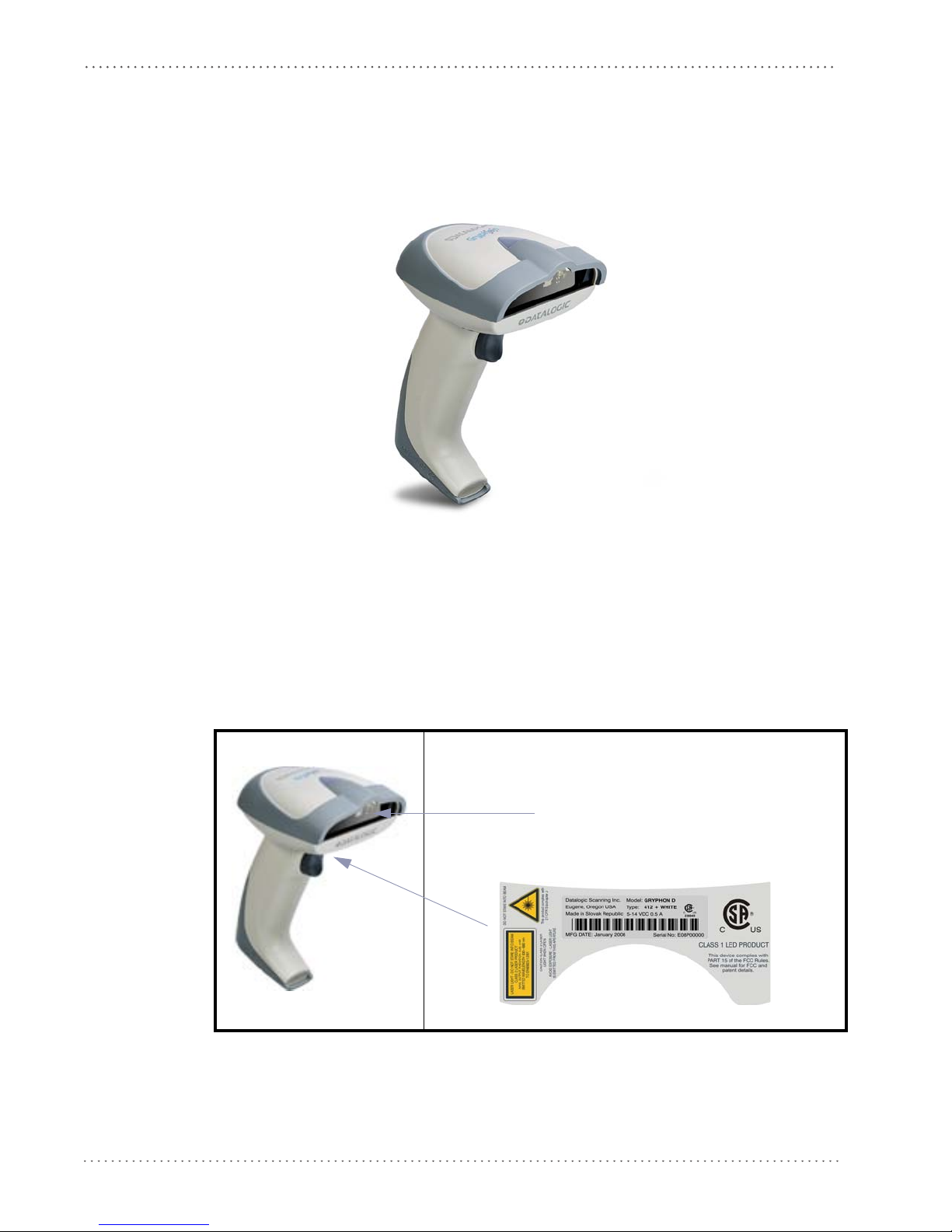
Aiming System Imager
Beam Output Window
General View
Figure 1. Gryphon™ D432/D412 Plus Reader
Compliance
Figure 2
. Gryphon™ D432/D412 Plus Reader Product Labels
4 Gryphon™ D432/D412Plus
CE Compliance
This is a Class A product. In a domestic environment this product may cause radio interference, in
which case the user may be required to take adequate measures.
WARNING
FCC Compliance
Modifications or changes to this equipment without the express written approval of Datalogic
could void the authority to use this equipment.
This device complies with Part 15 of the FCC Rules. Operation is subject to the following two
conditions: (1) This
any interference received, including interference which may cause undesired operation.
This equipment has been tested and found to comply with the limits for a Class A digital device,
pursuant to part 15 of the
protection against harmful interference when the equipment is operated in a commercial
environment. This equipment generates, uses, and can radiate radio frequency energy and, if
not installed and used in accordance with the instruction manual, may cause harmful
interference to radio communications. Operation of this equipment in a residential area is likely
to cause harmful interference in which case the user will be required to correct the interference
at his own expense.
Compliance
device may not cause harmful interference, and (2) this device must accept
FCC Rules. These limits are designed to provide reasonable
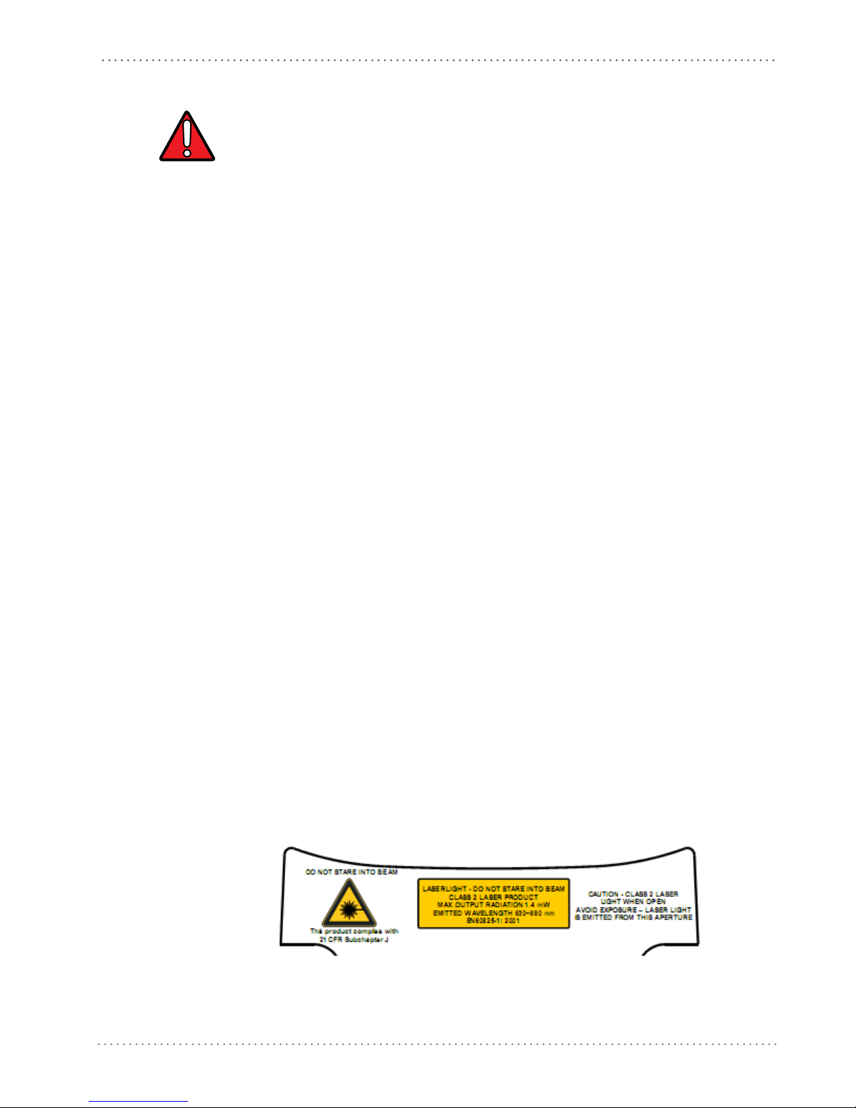
Laser Safety
The Gryphon D432/D412Plus hand-held reader is a Class 1 LED product regarding its
Illuminator and a Class 2 laser product regarding its Aiming System.
LED Illuminator
The use of an illuminator in the Gryphon D432/D412Plus Family is a Class 1 LED product:
Aiming System
The Gryphon D432/D412Plus aiming system meets the requirements for laser safety.
ILLUMINATORE LED CLASSE 1
AUSLEUCHTER LED KLASSE 1
ILLUMINATEUR A LED DE CLASSE 1
ILUMINADOR LED DE CLASE 1
Product Reference Guide 5
Preface: About this Guide
Table 1
. Laser Safety
I D F E
LA LUCE
LASER È
VISIBILE
ALL'OCCHIO
UMANO E
VIENE
EMESSA
DALLA
FINES
TRA
INDICATA
NELLA
FIGURA.
LUCE LASER
N FIS
NO
IL FASCIO
APPARECCHI
O LASER DI
CLASSE 2
MASSIMA
POTENZA
D'USCITA:
SARE
DIE LASERSTRAH
LUNG
IST FÜR DAS
MENSCHLICH
E AUGE
SICHTBAR
UND WIRD AM
STRAHLAUSTRITTSFENTST
ER
AUSGESENDET
(SIEHE BILD)
LASERSTRAHL
UNG NIC
HT IN
DEN STRAHL
BLICKEN
PRODUKT DER
LASERKLASSE 2
MAXIMALE
AUSGANGSLEI
STUNG:
LE RAYON
ER EST
LAS
VISIBLE À
L'OEUIL NU
ET IL EST
ÉMIS PAR LA
FENÊTRE
DÉSIGNÉE
SUR
L'ILLUSTRATI
ON DANS LA
FIGURE
RAYON LASER
EVITER DE
REGARDER LE
N
RAYO
APPAREIL
LASER DE
CLASSE 2
PUISSANCE
DE SORTIE:
LA LUZ LÁSER
ES VISIBLE AL
O
OJ
HUMANO Y
ES EMITIDA
POR LA
VENTANA
INDICADA EN
LA FIGURA.
RAYO LÁSER
NO MIRAR
FIJO EL RAYO
RATO
APA
LÁSER DE
CLASE 2
MÁXIMA
POTENCIA DE
SALIDA:
WARNING
LUNGHEZZA
D'ONDA
EMESSA:
CONFORME A
EN 6082
5-1
(2001)
WELLENLÄGE:
ENTSPR. EN
6082
5-1 (2001)
LONGUER
D'ONDE
EMISE:
CONFORME A
EN 60825
-1
(2001)
LONGITUD
DE ONDA
EMITID
A:
CONFORME A
EN 6082
5-1
(2001)
ENGLISH
The following information is provided to comply with the rules imposed by international
authorities and refers to the correct use of your terminal.
STANDARD LASER SAFETY REGULATIONS
This product conforms to the applicable requirem
60825-1 at the date of manufacture.
For installation, use and maintenance, it is not necess
Use of controls or adjustments or performance of procedures other than those specified herein may
result in exposure to hazardous visible laser light.
ents of both CDRH 21 CFR 1040 and EN
to open the device.
ary
The product utilizes a low-power laser diode. Alth
momentarily causes no known biological damage, avoid staring at the beam as one would with
6 Gryphon™ D432/D412Plus
ough staring directly at the laser beam
Compliance
any very strong light source, such as the sun. Avoid allowing the laser beam to hit the eye of an
observer, even through reflective surfaces such as mirrors, etc.
ITALIANO
Le seguenti informazioni vengono fornite dietro direttive delle autorità internazionali e si
riferiscono all’uso corretto del terminale.
NORMATIVE STANDARD PER LA SICUREZZA LASER
ATTENZIONE
Questo prodotto risulta conforme alle normative vigenti
produzione: CDRH 21 CFR 1040 e EN 60825-1.
Non si rende mai necessario aprire l’appa-recchio per
manutenzione.
L'utilizzo di procedure o regolazioni differenti da quelle d
care un'esposizione pericolosa a luce laser visibile.
Il prodotto utilizza un diodo laser a bassa potenza. Sebbene non siano noti danni riportati
dall’occhio umano in seguito ad una esposizion
così come si eviterebbe qualsiasi altra sorgente di luminosità intensa, ad esempio il sole. Evitare
inoltre di dirigere il raggio laser negli occhi di un osservatore, anche attraverso superfici
riflettenti come gli specchi.
e di breve durata, evitare di fissare il raggio laser
sulla sicurezza laser
motivi di installazione, utilizzo o
escritte nella documentazione può provo-
alla data di
DEUTSCH
Die folgenden Informationen stimmen mit den Sicherheitshinweisen überein, die von
internationalen Behörden auferlegt wurden, und sie beziehen sich auf den korrekten Gebrauch
vom Terminal.
NORM FÜR DIE LASERSICHERHEIT
ACHTUNG
Dies Produkt entspricht am Tag der Herstellung den gültige
CFR 1040 Normen für die Lasersicherheit.
Es ist nicht notwendig, das Gerät wegen Betrieb oder Installations-, und
öffnen.
Jegliche Änderungen am Gerät sowie Vorgehensweisen, die nicht in dieser Betriebsanleitung beschreiben we
Der Produkt benutzt eine Laserdiode. Obwohl zur Zeit keine Augenschäden von kurzen
Einstrahlungen bekannt sind, sollten Sie es vermeiden für längere Zeit in den Laserstrahl zu
schauen, genauso wenig wie in starke Lichtquellen (z.B. die Sonne). Vermeiden Sie es, den
Laserstrahl weder gegen die Augen eines Beobachters, noch gegen reflektierende Oberflächen zu
richten.
rden, können ein gefährliches Laserlicht verursachen.
n EN 60825-1 und CDRH 21
Wartungs-arbeiten zu
FRANÇAIS
Les informations suivantes sont fournies selon les règles fixées par les autorités internationales et
se réfèrent à une correcte utilisation du terminal.
Product Reference Guide 7
Preface: About this Guide
NORMES DE SECURITE LASER
Ce produit est conforme aux normes de sécurité laser en vigueur à sa date de fabrication: CDRH
21 CF
R 1040 et EN 60825-1.
ATTENTION
Il n’est pas nécessaire d’ouvrir l’appareil pour l’installati
on, l’utilisation ou l’entretien.
L'utilisation de procédures ou réglages différents de ceux donnés ici peut entraîner une dangereuse
exposition à lumière laser visible.
Le produit utilise une diode laser. Aucun dommage aux yeux humains n’a été constaté à la suite
d’une exposition au rayon laser. Eviter de regarder fixement le rayon, comme toute autre source
lumineuse intense telle que le soleil. Eviter aussi de diriger le rayon vers les yeux d’un
observateur, même à travers des surfaces réfléchissantes (miroirs, par exemple).
ESPAÑOL
Las informaciones siguientes son presentadas en conformidad con las disposiciones de las
autoridades internacionales y se refieren al uso correcto del terminal.
NORMATIVAS ESTÁNDAR PARA LA SEGURIDAD LÁSER
Este aparato resulta conforme a las normativas vigentes
producción: CDRH 21 CFR 1040 y EN 60825-1.
No es necesario abrir el aparato para la instalación, la utilización o la manutención.
de seguridad láser a la fecha de
ATENCION
CAUTION
La utilización de procedimientos o regulaciones diferentes de aquellas describidas en la documentación puede causar una exposición peligrosa a la luz láser visible.
El aparato utiliza un diodo láser a baja potencia. No son notorios daños a los ojos humanos a
consecuencia de una exposición de corta duración. Eviten de mirar fijo el rayo láser así como
evitarían cualquiera otra fuente de luminosidad intensa, por ejemplo el sol. Además, eviten de
dirigir el rayo láser hacia los ojos de un observador, también a través de superficies reflectantes
como los espejos.
The Gryphon D432/D412Plus Hand-Held Reader is not user-serviceable
. Opening the case of the unit
can cause internal damage and will void the warranty.
8 Gryphon™ D432/D412Plus

Compliance
WEEE Compliance
Waste Electrical and Electronic Equipment (WEEE) Statement
English
For information about the disposal of Waste Electrical and Electronic Equipment (WEEE),
please refer to the website at www.scanning.datalogic.com.
Italian
Per informazioni sullo smaltimento delle apparecchiature elettriche ed elettroniche consultare il
sito Web www.scanning.datalogic.com.
German
Informationen zur Entsorgung von Elektro- und Elektronik- Altgeräten (WEEE) erhalten Sie
auf der Webseite www.scanning.datalogic.com.
French
Pour toute information relative à l’élimination des déchets électroniques (WEEE), veuillez
consulter le site Internet www.scanning.datalogic.com.
Spanish
Si desea información acerca de los procedimientos para el desecho de los residuos del equipo
eléctrico y electrónico (WEEE), visite la página Web www.scanning.datalogic.com.
Portuguese
Para informações sobre a disposição de Sucatagem de Equipamentos Eléctricos e Eletrônicos
(WEEE - Waste Electrical and Electronic Equipment), consultar o site web
www.scanning.datalogic.com.
Chinese
有关处理废弃电气电子设备 (WEEE) 的信息, 请参考 Datalogic 公司的网站:
http://www.scanning.datalogic.com/。
Japanese
廃電気電子機器 (WEEE) の処理についての関連事項は Datalogic のサイト
www.scanning.datalogic.com, をご参照下さい。
Product Reference Guide 9

Preface: About this Guide
Power Supply
This device is intended to be supplied by a UL Listed or CSA Certified Power Unit marked
"Class 2" or "LPS" output rated 5-30 V, minimum 0.75 A (Gryphon 412Plus) or 5V, 0.6 A
(Gryphon 432) which supplies power directly to the scanner via the jack connector on the
cable.
Service and Support
Datalogic provides several services as well as technical support through its website. Log on to
www.scanning.datalogic.com and click on the links indicated for further information including:
PRODUCTS
Search through the links to arrive at your product page where you can download specific
Manuals and Software & Utilities including:
• Datalogic Aladdin™, a multi-platform
SERVICE & SUPPORT
• Technical Support - Product documentation and programming guides and Technical Sup-
• Service Programs - Warranty Extensions and Maintenance Agreements
• Repair Services - Flat Rate Repairs and Return M
• Downloads – Manuals & Documentation, Data Sheets, Product Catalogues, etc.
utility program that allows device configuration
using a PC. It provides RS-232 interface configuration as well as configuration barcode
printing.
port Department in the world
aterial Authorization (RMA) Repairs.
CONTACT US
Information Request Form and Sales & Service Network
10 Gryphon™ D432/D412Plus

Introduction
Gryphon D432/D412Plus Family Description
The Gryphon D432/D412Plus Family Hand-Held Reader packs a lot of performance into an
attractive, rugged, hand-held device. It operates in commercial and industrial environments as
well as the front office.
Chapter 1
Omni-directional
Operating
Decoding
and
Imaging
FLASH MEMORY
USA Driver License
r
sin g
Pa
Package Contents
The following parts are included in the Gryphon D432/D412Plus package contents:
• Gryphon D432/D412Plus Hand-Held Reader
• Gryphon D432/D412Plus Quick Reference Manual
To read a symbol or capture an image
D432/D412Plus Family is a powerful omni-directional reader, the orientation of the symbol is not
important.
Thanks to powerful algorithms, Gryphon D432/D412Plus reliably decodes all major 1D (linear) barcodes, 2D stacked codes (such as PDF417), 2D matrix s
POSTNET, PLANET). The data stream — acquired from decoding a symbol — is rapidly sent to the host.
The reader is immediately available to read another symbol.
Gryphon D432/D412Plus can also function as a camera
and other items.
Flash technology allows you to upgrade the Gryphon D
supported or as improved decoding algorithms become available.
The Gryphon D432/D412Plus reader can be set up to select
from USA Driver License PDF417 barcodes. This feature can be enabled using either Datalogic Aladdin™ or the barcodes in the USA Driver License Parsing Quick Reference Guide (QRG), available on
Datalogic website.
the
, you simply aim the reader and pull the trigger. Since Gryphon
y
mbols (such as DataMatrix), postal codes (such as
by capturing images of labels, signatures,
432/D412Plus reader as new symbologies are
and output a subset of data elements
You may want to save your packing material in case you need to ship the re
time.
Product Reference Guide 11
ader at some later

Introduction
Configuration Methods
Reading Configuration Codes
This manual can be used for complete setup and configuration. If you wish to change the
default settings, you can configure the Gryphon D432/D412Plus reader by reading the
programming code symbols in this manual. Configuration commands and their relative
arguments are read individually using the symbols in this manual. See Appendix D.
Using Datalogic Aladdin™
The Datalogic Aladdin™ program, available for download from the Datalogic Web site, allows
programming the reader by selecting configuration commands or printing them through a userfriendly graphical interface running on the PC. These commands are sent to the reader over the
current communication interface, or they can be printed to be read.
Sending Configuration Strings from Host
An alternative configuration method is provided in Appendix A using the RS-232 or USB
COM interface. This method is particularly usef
with the same settings. Batch files containing the desired parameter settings can be prepared to
configure devices quickly and easily.
ul when many devices need to be configured
The Gryphon D432/D412Plus reader incorporates a
connected to a Host by plugging the correct interface cable into the connector and closing the
cable cover.
multi-standard interface, which can be
12 Gryphon™ D432/D412Plus
Aiming System
The Gryphon D432/D412Plus reader uses an intelligent aiming system similar to those on
cameras. By partially pulling the trigger, the aiming system indicates a field of view to be
positioned over the code:
Figure 3. Aiming System
Chapter 2
Using the Gryphon D432/412Plus
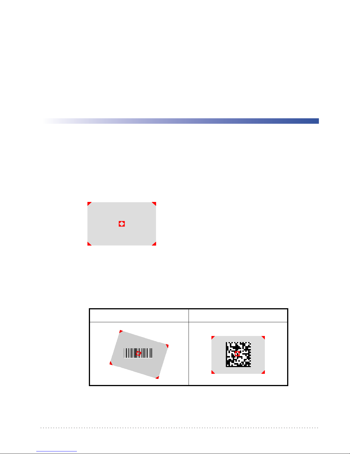
When you pull the trigger completely a red beam illuminates the code. If the aiming system is
centered and the entire symbology is within the aiming system, you will get a good read. The
field of view changes size as you move the reader closer or farther away from the code.
Figure 4
The field of view indicated by the aiming system will be smaller when the Gryphon D432/
D412Plus is closer to the code and larger when it is farther from the code. Symbologies with
smaller bars or elements (mil size) should be read closer to the unit. Symbologies with larger bars
. Relative Size and Location of Aiming System Pattern
Linear barcode 2D Matrix symbol
Product Reference Guide 13

Using the Gryphon D432/412Plus
or elements (mil size) should be read farther from the unit. (See "Technical Features" starting on
page 119 for further details).
Normal Operation
Gryphon D432/D412Plus normally functions by capturing and decoding codes.
Point the reader at the target and pull the trigger partially to enable the aiming system. Then,
pul
l it completely to capture and decode the image. The reader will repeatedly flash until the
symbol is decoded or timeout is reached. In between the flashes of the reader, the aiming system
keeps on showing the field of view on the target (see Figure 4 on page 13
As you are reading code symbols, adjust the distance at which you are holding the reader.
The Gryphon D432/D412Plus hand-held reader aiming system is designed for general reading and decoding of 1D and 2D
symbols. Some variation in reading distance will occur due to narrow bar width and other factors.
If reading codes positioned on reflective surfaces, it may be necessary to tilt the reader with respect to the barcode.
).
14 Gryphon™ D432/D412Plus

Image Capturing
Gryphon D432/D412Plus can also function as a camera by capturing images of labels,
signatures, and other items.
In order to capture an image, the user should read a Capture Image code (see page 80), then
point at the image subject and pull the trigger. This way, the image will be captured and sent to
the host PC. G
image you must read another Capture Image Code of the same or a different Preset
Configuration.
Normal Operation
ryphon D432/D412Plus then returns to normal operation. To capture another
You can use the aiming system to position the reader fr
centered over the target). Adjust the distance at which you are holding the reader (see Figure 4
on page 13).
If the RS-232 interface has been selected, the image will be transferred to the host PC via
XMODEM_1K protoco
Image capturing is not available in Wedge and USB Keyboard Emulation interfaces and is not compatible with Autoscanning
nor when the Software trigger type is selected.
Up to four different and independent Image Presets can be defined (see page 81).
l.
om the object (ensure the reader is about
Basic Configuration Parameters
The Image file formats supported are: TIFF, JPEG (default).
The resolution available is 752 x 480 pixels.
For JPEG images it is possible to define the Image Quality level to address tradeoff
image file size and quality.
between
Advanced Configuration Parameters
By default, for all Image Presets, the window has its original coordinates equal to zero, its width
equal to 752 pixels and its height to 480 pixels.
Brightness Adjustment is availab
Positive values shift the luminance up so that the image will result brighter. Default value is 0%,
meaning that no brightness adjustment is performed.
The same range of values (–100% up to 100%, in
Adjustment. Positive values will increase the contrast, so that dark and bright objects inside the
image will be better distinguishable. Default value is 0%, which means that no contrast
adjustment is performed.
You can set the Image Color Depth by selecting 256 gray levels (def
gray levels. Higher color depths yield larger image files. This option is ignored if the JPEG
format is selected, (256 gray levels only).
le in the range from –100% up to 100%, in steps of 1%.
steps of 1%) is available for Contrast
ault), 16 gray levels, or 2
Product Reference Guide 15

Using the Gryphon D432/412Plus
Autoscanning
Normal Mode
Gryphon D432/D412Plus provides an autoscan command (see page 78), which when enabled,
causes the reader to scan continuously and to monitor th
way, Gryphon D432/D412Plus is ready to capture any image (containing a potential code)
positioned on a
The aiming system can be enabled to indicate the reading area of the potential code to be
captured. The
not sufficient to autodetect the potential code to be captured; furthermore, the illumination
system increases in intensity for an instant when capturing and decoding an image. A safety time
may be defined to prevent Gryphon D432/D412Plus from reading the same code repeatedly.
If the decoding is completed successfully, the reader starts monitoring the reading area again. In
case of
decoding failure, Gryphon D432/D412Plus keeps on decoding until a potential code is
present in the central zone of the reading area.
Pattern Mode
The Autoscan pattern mode is particularly advised when reading barcodes positioned on a nonuniform background. In these cases Gryphon D432/D412Plus may perceive some elements of
the background as barcodes and start the decoding. To avoid this undesired effect, the Autoscan
Pattern Code is placed in the Gryphon D432/D412Plus reading area which prevents decoding.
Using this code as the background, code reading takes place normally by presenting desired
codes to be read over the Pattern Code. Between each code read, the Pattern Code must be
presented to the reader.
illumination system can also be enabled when the ambient light conditions are
e central zone of its reading area. In this
uniform background.
The Pattern Code can be printed from this manual (see Appendix D).
In case of low ambient light conditions, Gryphon D432/D412Plus automatically activates the
illuminat
ion system. If desired, the illumination system can be enabled so that it is always active.
Defining Data Formatting
The string of a decoded code to be sent to the host may be formatted as follows:
• defining simple data formatting (see page 48);
• defining advanced data formatting giving complete flexibility in changing the format of
data (see "Advanced Data Format"on page 91).
When both simple and advanced data formatting
following order:
1. The string of the decoded code is processed acc
2. The resulting string is processed according to th
formatting;
3. Character substitution is performed on the resulting string;
4. Character deletion is performed on the
are selected the info is processed in the
ording to the advanced formatting rules;
e selection type rules of the simple data
resulting string;
5. Code concatenation is performed;
16 Gryphon™ D432/D412Plus

6. Code ID is attached to the resulting string;
Normal Operation
7. Global headers and terminators are attach
The codes to be sent to the host may also be selected or ordered depending on the following two
conditions:
• one code per scan: Gryphon D432/D412Plus s
center. If the "Central Code Transmission" command is enabled, only the code containing
the image center will be transmitted (see page 77);
• all codes per scan: the codes to be sent to the host may be ordered either by length or by
symbology star
enabling both these criteria, codes belonging to the same symbology are sent to the host
depending on their
ting from the code being closest to the image center (see page 77). When
length.
ed to the resulting string;
ends the code being closest to the image
Concatenation
It is possible to concatenate up to 4 different codes, set their length and enable the intercode
delay between them (the intercode delay is set in the specific interface parameters. When
enabling the delay one or more global headers and terminators are added to the decoded data.
The concatenation procedure may occur in different ways depending on the number of codes to
be decoded per image.
One Code Per Scan
• If the code resulting from the single decoding of an image belongs to one of the code fam-
ilies to be concatenated, it is saved to th
other codes to complete the concatenation.
• If the code belongs to the same family of a code previously saved, it overwrites the old one.
• If the code resulting from the decoding does not belong
concatenated, it causes the concatenation failure and clears the temporary memory. If the
"Concatenation Failure Transmission" command is set to "Tx codes causing failure" (see
page 56), this code will be sent in the output message.
e Gryphon D432/D412Plus memory waiting for
to one of the code families to be
All Codes Per Scan
• All codes resulting from the decoding of an image and belonging to one of the families to
be concatenated are saved to the Gryphon D432/D412Plus memory waiting for other
codes to complete the concatenation.
• If one or more codes resulting from the decoding belong
viously saved, they overwrite the old ones.
• When the image contains no code to be concatenated,
reader temporary memory is cleared. If the "Concatenation Failure Transmission" command is set to "Tx codes causing failure" (see page 56), the codes causing the concatenation failure will be sent in the output message.
to the same family of codes pre-
the concatenation fails and the
Product Reference Guide 17

Using the Gryphon D432/412Plus
NOTES
18 Gryphon™ D432/D412Plus
This procedure allows setting up the reader to operate with the default settings. Whenever you
need to change the default values refer to "Changing Default Settings" on page 30.
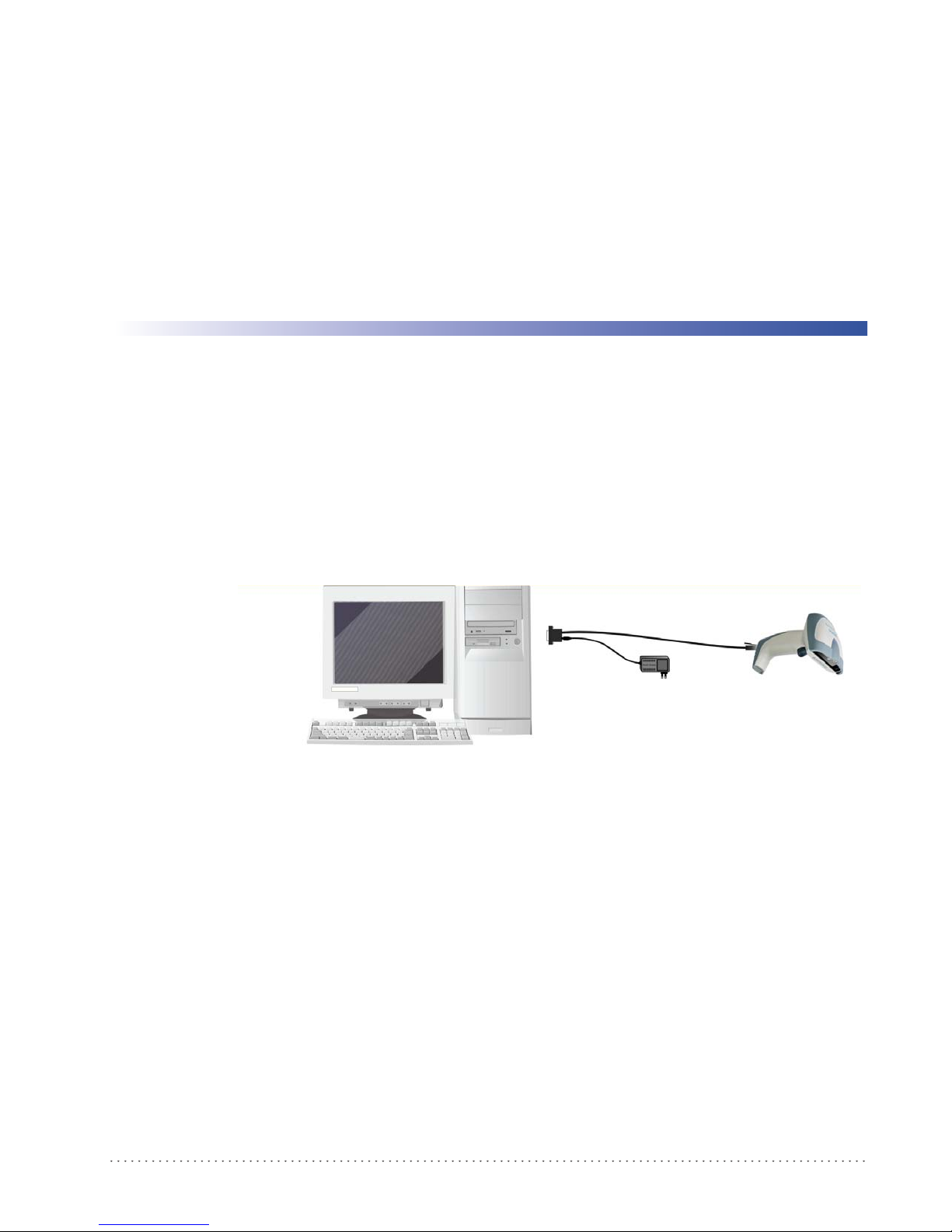
RS-232 Interface Selection
The Gryphon D432/D412Plus reader requires the RS-232 interface cable and the AC/DC
power adapter to be connected.
Chapter 3
Initial Setup
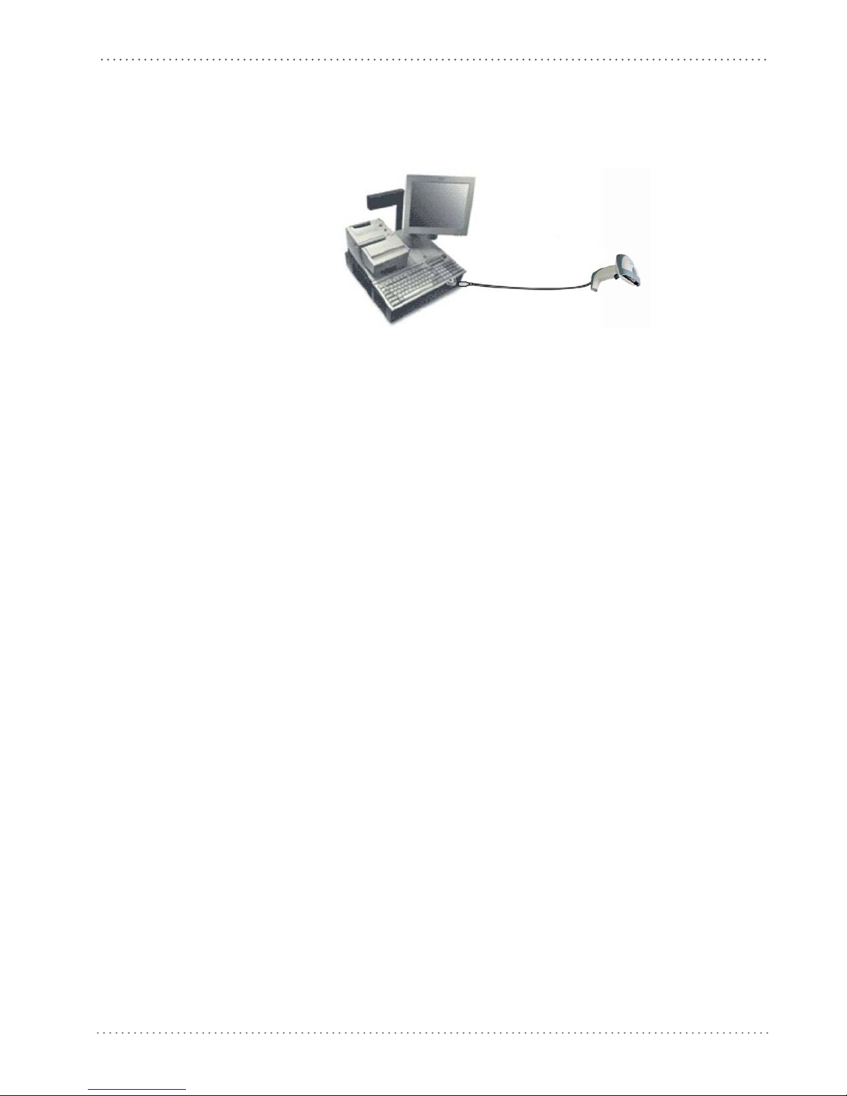
To install and configure your reader with the RS-232
1. Make all system connections as shown:
2. Read the restore default parameter code below:
Restore Default
AMHKGPAOFNGNENEIEPANHOGOCK
AHHPMBAMDKEOFMHMLJALECHGIK
AKCBPJCJGIIJCMCFGPLCMMMNLK
AEFBJLBGMHPKMOGNKKNDPDMGGK
AAPHBAJIDGHPOJKEFPNCEACBHK
AFKFBKNGLGMOMELLGOPCMJFKIK
DDDDLDLLLDDLLLLDDDLDDLDLDL
3. Read the RS-232 interface selection code:
RS-232
AMHKHMFOHNGNENEIEPANHOGOCK
AGPEPJAMDKEOFMHMLJAKFEHFKK
AMGNPJCJGIIJCMCEGJMHNDOLLK
AIFBJLBGMHPLNKECPCGMBBIBOK
AAPHBAJJDAAGMGKDDAOHBGGLHK
AEKFBONJCDDIECLFJIJKMCHLIK
DLDDLDLDLLDLLLLDLLDDDLDLLL
interface, follow these instructions:
4. Power up your PC.
RS-232 is the default interface set at the factory.
Product Reference Guide 19
Initial Setup
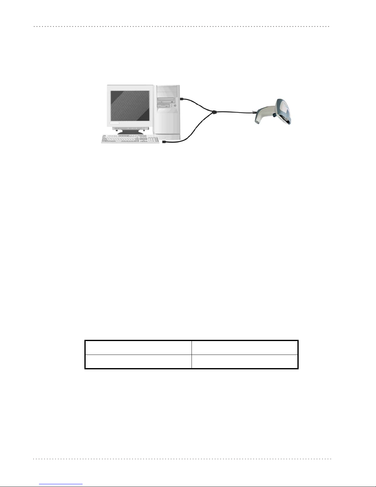
Wedge Interface Selection
The Gryphon D432Plus reader requires the Wedge interface cable.
To install and configure your reader with the Wedge
1. Connect the cable to the Gryphon D432Plus re
2. Power up your PC.
3. Read the restore default parameter code below:
Restore Default
AMHKGPAOFNGNENEIEPANHOGOCK
AHHPMBAMDKEOFMHMLJALECHGIK
AKCBPJCJGIIJCMCFGPLCMMMNLK
AEFBJLBGMHPKMOGNKKNDPDMGGK
AAPHBAJIDGHPOJKEFPNCEACBHK
AFKFBKNGLGMOMELLGOPCMJFKIK
DDDDLDLLLDDLLLLDDDLDDLDLDL
4. Read the Wedge IBM AT interface selection code:
interface, follow these instructions:
ader and to the PC as shown:
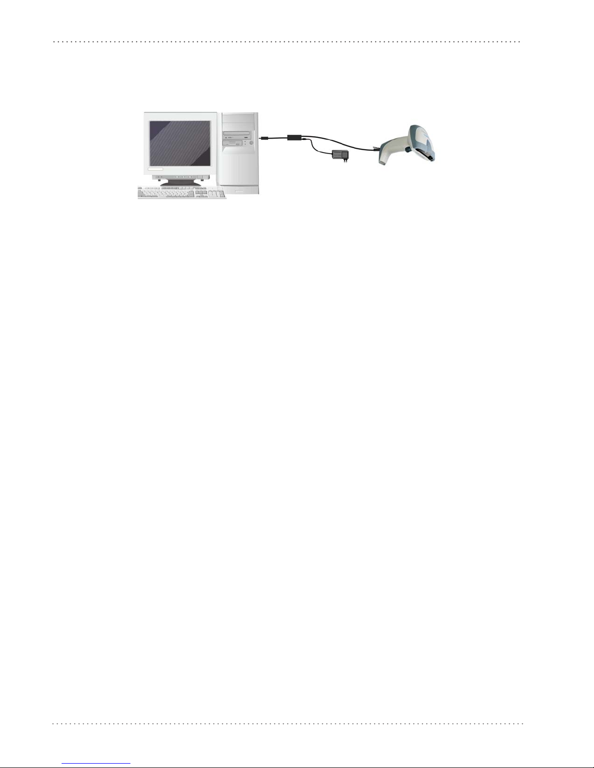
USB Interface Selection
The Gryphon D432/D412Plus reader requires the USB interface cable and, if required, the
AC/DC power adapter to be connected.
The USB interface is comp
Windows 98 (and later) IBM POS for Windows
Mac OS 8.0 (and later) 4690 Operating System
Start-Up
As with all USB devices, upon connection, the Host performs several checks by communicating
with the Gryphon D432/D412Plus. During this phase the green LED on the Gryphon
D432/D412Plus reader blinks and normal operations are suspended. Two basic conditions
must be met before Gryphon D432/D412Plus is ready to read codes: the correct USB driver
must be loaded and sufficient power must be supplied to the reader.
atib
le with:
Wedge – IBM AT
AMHKHMFOHNGNENEIEPANHOGOCK
AGPEPJAMDKEOFMHMLJALFAEHKK
AEONPJCJGIIJCMCEHPLLHLPPJK
AIFBJLBGMHPLNPDFHGDGFIBDOK
AAPHBAJJCGCOPJDIMBCEANODDK
AFKFBPPJPJCAALOIKIECIPIKLK
DDLDLDLDDLDLLLLDDDDDDLDLDL
For all systems, the correct USB driver for the default USB-KBD inte
HID interface is included in the Host Operating System and will either be loaded automatically
20 Gryphon™ D432/D412Plus
rface or the USB Generic
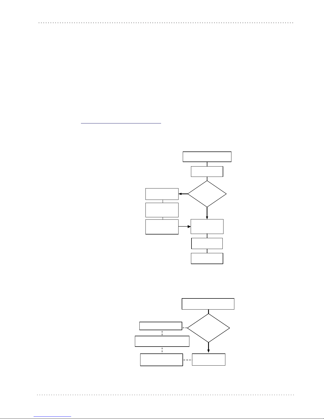
USB Interface Selection
box appear
power is not
sufficient?
Gree n LED o ff
Sele ct desir ed USB
interface code
(US B-KBD is defau lt)
NO
YES
R ead test codes .
Reader is READY
Load drivers
(if req uested)
Load drivers
(if req uested)
G
G
- BEEP OK
BEEP OK
Connect Gryphon™
D432/ D412Plus to Host
Disconnect reader
at Host
power supply to
cable and power up
Re co nne ct re ad er
cable to Host and
close dialog box
1.
2.
NO
YES
Read test c odes.
Reader is READY
Green LED blinks
Gree n LED o ff - BEEP OK
BEEP OK
Connect Gryphon™
D432/D412Plus to Host
Disconnect reader at Hos t
ca ble an d po wer up
Rec onnect reader cable to
Host and close dialog box
appear warning
that Bus power is
not su ffici ent?
or will be suggested by the O.S. and should therefore be selected from the dialog box (the first
time only).
If the Host supplies sufficient power to the reader,
the start-up phase ends correctly, the green
LED stops blinking and the reader emits the beep OK signal.
If the Host does not supply sufficient power to the reader, a dialog box will appear on the Host
and th
ader will be blocked (green LED continues blinking). In this case, disconnect the USB
e re
cable at the Host (green LED stops blinking), connect and power-up an external supply to USB
cable then reconnect the USB cable to the Host and close the dialog box. The reader emits the
beep OK signal. You can now read codes. At this point you can read the USB interface
configuration code according to your application. Load drivers from the O.S. (if requested).
When configuring the USB-COM interface or DLBulkUSB inter
face, the relevant files and
drivers must be installed and can be downloaded from the web site
http://www.scanning.datalogic.com.
The reader is ready.
FIRST START-UP
ree n LED blin ks
Does a dialog
war ni ng th at Bus
Successive start-ups will automatically recognize the previously loaded drivers. If external power
is used, verify that external power is already supplied.
Product Reference Guide 21
Connect external
SUCCESSIVE START-UPS
Connect ex ternal power supply to
reen LED off
Does a dialog box
Initial Setup
To install and configure your reader with one of the USB interfaces, see the "First Start-up"
diagram above and follow these instructions.
1. Make all the Gryphon D432
/D412Plus reader connections as shown:
USB Connections
2. Power up your PC.
3. Read the desired USB interface selection code:
USB-COM EMULATION USB-KBD EMULATION
AMHKHMFOHNGNENEIEPANHOGOCK
AGPEPJAMDKEOFMHMLJALEAGEKK
AMONPJCJGIIJCMCFHLPMOOKNBK
AIFBJLBGMHPLMLAMDPIKFBLBOK
AAPHBAJICHGNBKOPLNBGLPAHFK
AHKFBNPHFKLEAOHGLPKOGDJLLK
DLDDLDLDDLDLLLLDDDLDDLDLDL
AMHKHMFOHNGNENEIEPANHOGOCK
AGPEPJAMDKEOFMHMLJAKEDBEKK
AMGNPJCJGIIJCMCFHMNJLBJPHK
AIFBJLBGMHPKNMBGMJOJEHHAOK
AAPHBAJICDHCJBCNKPCNNJNFHK
AFLFBMPJIKPAMFFBBHKCCKNIKK
DLLDLDLDLLDLLLLDDDDDDLDLLL
USB BULK USB Generic HID
AMHKHMFOHNGNENEIEPANHOGOCK
AGPEPJAMDKEOFMHMLJAKFDDHKK
AEGNPJCJGIIJCMCEHIJOCEMNPK
AIFBJLBGMHPKMICPIAFFEONCOK
AAPHBAJJCCDBHCPKNDBPGLDBBK
AHLFBOPHCJGEMAMPAAEOMGMJKK
DDDDLDLDLLDLLLLDDDLDDLDLLL
AMHKHMFOHNGNENEIEPANHOGOCK
AGPEPJAMDKEOFMHMLJALEHCGKK
AEONPJCJGIIJCMCFGKKFBJILFK
AIFBJLBGMHPKNJGBENLDAOOCOK
AAPHBAJIDFFKKOLGFOOOMCFNDK
AELFBNNJFAOIIMAMCHHKGHCJJK
DDDDLDLDDLDLLLLDLLDDDLDLDL
22 Gryphon™ D432/D412Plus
USB Interface Selection
IBM PORT 9B/PORT 5B/IBM USB
*The IBM PORT 9B and IBM PORT 5B are only for Gryphon D412 + models.
1. Make all the Gryphon D432/D412Plus reader connections as shown:
2. Read the desired IBM interface selection codes:
IBM PORT 9B IBM PORT 5B
AMHKHMFPHMGNEJEIEPANHOGOCK
AGPFONFCPKEOFMHMLJALEABEKK
AHCPLNCJGIIJCMCEHNPGDOEBCK
AAFBJLBGMHPKMPHKHIHFLPANKK
AAPHBAJICBFFGJNMEFIBBCHBBK
AGKFBILMPCDMDEFEFKKMEDKLLK
DLDDLDLDLDLLLLLDDLDDDLDLDL
Gryphon D412 + models only
IBM USB
AMHKHMFOHNGNENEIEPANHOGOCK
AGOEPJAMDKEOFMHMLJAKECFEKK
AMONPJCJGIIJCMCFGMMHLFIFJK
AIFBJLBGMHPKMLBHKCCKPLJDOK
AAPHBAJIDDFDDLPAENDNINCJHK
AHKFBNJDHPIEOENLMJAAEBAIJK
DDDDLDLDLLLLLLLDDLLDDLDLLL
AMHKHMFPHMGNEJEIEPANHOGOCK
AGPFONEDPKEOFMHMLJAKEFFHKK
AHCPLNCJGIIJCMCEHMLILIKJGK
AAFBJLBGMHPLNIFNPNEPPFMNKK
AAPHBAJJCCAFHGAJDDKJMHFFFK
AELFBINACDBGBBGHDPBAIMCLLK
DDDDLDLDDDLLLLLDLLLDDLDLDL
Product Reference Guide 23

Initial Setup
NOTES
24 Gryphon™ D432/D412Plus

Chapter 4
Configuration Using Code Symbols
This section describes the programming method of using configuration code symbols to
program your reader. By using the Gryphon D432/D412Plus reader to read/decode these
special configuration symbols, you can configure, and obtain information from its system
software.
When you are reading configuration code symbols,
2D reader to avoid reading adjacent symbols.
The configuration code symbols in this chapter are divided into logical sections according to the
type
of configuration required, (RS-232 configuration, Code selection, etc.). If arguments are
required with a command, you can read additional code labels (typically digits) from
Appendix D.
USA Driver License Parsing is a feature not covered in this manual. For more information, reference the “USA Driver License Parsing
Quick Reference Guide”, available on the Datalogic website at www.scanning.datalogic.com.
To configure your reader:
1. Read the Enter Configuration code ONC
2. Modify the desired parameters in one or more sections by reading the parameter code and
lecting the value from the Hex/Numeric table (see Appendix D) or
se
given procedures.
3. Read the Exit and Save Configuration code ONCE, av
Example for step 3
carefully aim the Gryphon D432/D412Plus
E, available on top of each page.
by following the
ailable on top of each page.
To set the maximum length of characters in a Code 39 barcode symbol that the reader will
decode t
o 32:
• first read the Maximum Length symbol for Code 39 on page 61
• then read the symbol for the digit "3" and lastly the symbol for the digit "2" in
Appendix D.
Product Reference Guide 25

Configuration Using Code Symbols
Default Settings
Configuration Field Default Setting
RS-232 Communication
Baud Rate 115200
Parity, Data Bits, Stop Bits No parity; 8 Data bits; 1 Stop bit
Handshake None
ACK/NACK Protocol None
FIFO Enabled
Intercharacter Delay 0
Intercode Delay 0
RX Timeout 10 seconds
Serial Trigger Lock Disabled
Serial Trigger Lock Disable Character NUL
Serial Trigger Lock Enable Character NUL
USB COM Emulation
Handshake None
ACK/NACK Protocol None
FIFO Enabled
Intercharacter Delay 0
Intercode Delay 0
RX Timeout 10 seconds
USB Keyboard Emulation
FIFO Enabled
Intercharacter Delay 0
Intercode Delay 0
*Keyboard Nationality USA
*Keyboard Speed Normal
WEDGE-Communication
*Keyboard Nationality USA
CapsLock OFF
CapsLock Auto-Recognition ON
NumLock OFF
Intercharacter Delay 0
Intercode Delay 0
IBM 46xx Interface DEFAULT SETTINGS
protocol= Port 5B 1520, format = IBM Standard Format
IBM USB Interface DEFAULT SETTINGS
device usage Handheld
* The default values of these parameters are set when reading the interface selection.
26 Gryphon™ D432/D412Plus

Configuration Field Default Setting
Data Format-Symbology Independent Parameters
Code Identifier Disabled
Custom Code Identifier Disabled
Code Length Disabled
*Header No headers
CR and LF terminators for RS-232, USB BULK, USB COM, USB
neric HID
*Terminator
Data Format-Symbology Dependent Parameters
Symbology Specific Format Select All
Header Symbology No headers
Terminator Symbology No terminators
Symbology Character Substitution No character to substitute
Symbology Character Deletion No character to delete
Data Format-Concatenation
Concatenation Disabled
Define Concatenation 2 EAN/UPC codes concatenated
Set First Concatenated Code Length 000 = any length
Set Second Concatenated Code Length 000 = any length
Set Third Concatenated Code Length 000 = any length
Set Fourth Concatenated Code Length 000 = any length
Concatenation with Intercode Delay Disabled
Concatenation Timeout 10 seconds
Concatenation Failure Transmission Tx codes causing failure
Transmission after Timeout No code transmission
Concatenation Result Code ID No code Identifier
Ge
ENTER terminator for Wedge, USB Kbd
Default Settings
Advanced Formatting
Format enable/disable Disabled
Camera Control
Exposure Mode Automatic, based on entire image
Power Save
Illumination Power Max power
Illumination System Power ON
Code Selection
Issue Identical Codes Enabled
EAN/UPC
Selection Enabled
Add-On Disabled
UPCE Expansion Disabled
Code 39
Selection Enabled - no check digit
Code 39 Full ASCII
Disabled
Product Reference Guide 27

Configuration Using Code Symbols
Configuration Field Default Setting
Code Length Check Disabled
Minimum Length 001
Maximum Length 255
Start/Stop Character Disabled
Code 32
Selection Disabled
Interleaved 2 of 5
Selection Disabled
Code Length Check Disabled
Minimum Length 014
Maximum Length 255
Codabar
Selection Disabled
Code Length Check Disabled
Minimum Length 001
Maximum Length 255
Code 128
Code128 Selection Enabled
Code Length Check Disabled
Minimum Length 001
Maximum Length 255
EAN 128
Selection Disabled
Code Length Check Disabled
Minimum Length 001
Maximum Length 255
Code 93
Selection Disabled
Code Length Check Disabled
Minimum Length 001
Maximum Length 255
PDF417
Selection Enabled
Option Macro PDF417 Buffered Mode
Micro PDF417 Disabled
GS1 DataBar™ Family
GS1 DataBar Expanded Disabled
GS1 DataBar Limited Disabled
GS1 DataBar Omnidirectional Disabled
GS1 DataBar Expanded Stacked Disabled
GS1 DataBar Stacked
28 Gryphon™ D432/D412Plus
Disabled
 Loading...