

Datalogic Gryphon 2D Series, Gryphon I GD4500, Gryphon I GBT4500, Gryphon I GM4500 Product Reference Manual
Page 1

Gryphon™ 2D Family
Product Reference Guide
Gryphon I GD/GBT/GM4500
General Purpose Handheld
Area Imager Bar Code Reader
Page 2

Datalogic S.r.l.
Via S. Vitalino, 13
40012 Calderara di Reno (BO)
Italy
Tel. +39 051 3147011
Fax +39 051 3147205
©2011 - 2019 Datalogic S.p.A. and/or its affiliates
An Unpublished Work - All rights reserved. No part of the contents of this documentation
or the procedures described therein may be reproduced or transmitted in any form or by
any means without prior written permission of Datalogic S.r.l. or its subsidiaries or affiliates ("Datalogic" or “Datalogic S.r.l.”). Owners of Datalogic products are hereby granted a
non-exclusive, revocable license to reproduce and transmit this documentation for the
purchaser's own internal business purposes. Purchaser shall not remove or alter any proprietary notices, including copyright notices, contained in this documentation and shall
ensure that all notices appear on any reproductions of the documentation.
Should future revisions of this manual be published, you can acquire printed versions by
contacting your Datalogic representative. Electronic versions may either be downloadable
from the Datalogic website (
visit our website and would like to make comments or suggestions about this or other
Datalogic publications, please let us know via the "Contact Datalogic" page.
www.datalogic.com) or provided on appropriate media. If you
Disclaimer
Datalogic has taken reasonable measures to provide information in this manual that is
complete and accurate, however, Datalogic reserves the right to change any specification
at any time without prior notice.
Datalogic and the Datalogic logo are registered trademarks of Datalogic S.p.A. in many
countries, including the U.S. and the E.U. Gryphon is a trademark of Datalogic S.p.A. and/or
its affiliates, registered in the U.S. All other brand and product names may be trademarks
of their respective owners.
Patents
See www.patents.datalogic.com for patent list.
Page 3

Table of Contents
INTRODUCTION ....................................................................................................................................................... 1
About this Manual .............................................................................................................................................................1
Overview ....................................................................................................................................................................1
Manual Conventions .................................................................................................................................................2
Technical Support ..............................................................................................................................................................2
Datalogic Website Support ......................................................................................................................................2
Reseller Technical Support ......................................................................................................................................2
Telephone Technical Support ..................................................................................................................................2
About the Scanner .............................................................................................................................................................3
Using the GD4500 Reader ........................................................................................................................................3
Using the WLC4090 Radio Base .......................................................................................................................................4
Radio Base LEDs .......................................................................................................................................................4
Battery Safety ....................................................................................................................................................................5
Programming the Reader .................................................................................................................................................7
Configuration Methods ............................................................................................................................................7
SETUP....................................................................................................................................................................... 9
Unpacking ...........................................................................................................................................................................9
Setting Up the Scanner .....................................................................................................................................................9
Connect Host Interface ......................................................................................................................................... 10
Stand Installation .................................................................................................................................................. 12
Hands-Free Stand/Holder .................................................................................................................................... 12
Setting Up the Reader .................................................................................................................................................... 13
Positioning the Base Station ................................................................................................................................ 14
Reader, Cradle and LEDs Description ........................................................................................................................... 17
Connecting the Base Station ......................................................................................................................................... 18
Securing the DC Power Cord (Optional) ............................................................................................................... 19
System and Network Layouts ....................................................................................................................................... 21
Stand Alone Layouts ............................................................................................................................................. 21
Using the GBT/GM4500 Scanner .................................................................................................................................. 22
Scanner LEDs ......................................................................................................................................................... 22
Using the WLC4090 Radio Base .................................................................................................................................... 23
Radio Base LEDs .................................................................................................................................................... 23
Replacing the Battery Pack ........................................................................................................................................... 24
Using the Gryphon™ I GD/GBT/GM4500 ...................................................................................................................... 26
Linking the Reader ......................................................................................................................................................... 28
Link Scanner as Serial Device to a Bluetooth Host ............................................................................................ 28
Link Scanner as HID device to a Bluetooth host ................................................................................................ 29
Power Off ......................................................................................................................................................................... 29
Interface Selection .......................................................................................................................................................... 30
Configuring the Interface ...................................................................................................................................... 30
Customizing Configuration Settings ............................................................................................................................ 34
Using the Programming Bar Codes ..................................................................................................................... 34
Interface Settings .................................................................................................................................................. 35
Configuring Other Features .................................................................................................................................. 35
Software Version Transmission ........................................................................................................................... 35
CONFIGURATION USING BAR CODES.................................................................................................................. 37
Configuration Parameters ............................................................................................................................................. 37
Global Interface Features .............................................................................................................................................. 39
Host Commands — Obey/Ignore ........................................................................................................................ 39
USB Suspend Mode ............................................................................................................................................... 39
RS-232 ONLY INTERFACE 41
RS-232 Standard Factory Settings ............................................................................................................................... 41
Product Reference Guide i
Page 4

Baud Rate ........................................................................................................................................................................ 41
Data Bits .......................................................................................................................................................................... 42
Stop Bits ........................................................................................................................................................................... 43
Parity ................................................................................................................................................................................ 43
Handshaking Control ...................................................................................................................................................... 44
RS-232/USB-COM INTERFACES 45
Standard Factory Settings ............................................................................................................................................. 45
Intercharacter Delay ....................................................................................................................................................... 46
Beep On ASCII BEL .......................................................................................................................................................... 47
Beep On Not on File ........................................................................................................................................................ 47
ACK NAK Options ............................................................................................................................................................ 48
ACK Character ......................................................................................................................................................... 49
NAK Character ........................................................................................................................................................ 49
ACK NAK Timeout Value ........................................................................................................................................ 50
ACK NAK Retry Count ............................................................................................................................................ 51
ACK NAK Error Handling ....................................................................................................................................... 52
Indicate Transmission Failure ....................................................................................................................................... 53
Disable Character ............................................................................................................................................................ 53
Enable Character ............................................................................................................................................................. 54
KEYBOARD INTERFACE 55
Country Mode .................................................................................................................................................................. 56
Setup on PC to use ALT Universal ........................................................................................................................ 56
Setting Country Mode ........................................................................................................................................... 57
Setting Encoding Type ........................................................................................................................................... 71
Setting ALT output type ........................................................................................................................................ 78
Caps Lock State ............................................................................................................................................................... 79
Numlock ........................................................................................................................................................................... 79
Keyboard Numeric Keypad ............................................................................................................................................ 80
Keyboard Send Control Characters ............................................................................................................................... 81
Wedge Quiet Interval ..................................................................................................................................................... 82
Intercharacter Delay ....................................................................................................................................................... 83
Intercode Delay ............................................................................................................................................................... 84
USB Keyboard Speed ...................................................................................................................................................... 85
USB-OEM INTERFACE 87
Introduction ..................................................................................................................................................................... 87
Standard Factory Settings ............................................................................................................................................. 87
USB-OEM Device Usage ................................................................................................................................................. 88
USB-OEM Interface Options .......................................................................................................................................... 88
IBM 46XX INTERFACE 89
46xx Number of Host Resets ................................................................................................................................ 90
Transmit Labels in code 39 Format ..................................................................................................................... 92
Interface Options ................................................................................................................................................... 92
DATA FORMAT 93
Global Prefix/Suffix ........................................................................................................................................................ 94
Global AIM ID ................................................................................................................................................................... 95
GS1-128 AIM ID ............................................................................................................................................................... 95
Label ID ............................................................................................................................................................................ 96
Label ID: Pre-loaded Sets ...................................................................................................................................... 96
Label ID: Set Individually Per Symbology ............................................................................................................. 97
Label ID Control ...................................................................................................................................................... 97
Label ID Symbology Selection ............................................................................................................................... 98
Case Conversion ............................................................................................................................................................ 103
Character Conversion ................................................................................................................................................... 104
READING PARAMETERS 105
Double Read Timeout ................................................................................................................................................... 106
Reading Performance ................................................................................................................................................... 108
LED and Speaker Indicators ......................................................................................................................................... 109
Power On Alert ..................................................................................................................................................... 109
Good Read: When to Indicate ............................................................................................................................. 110
Good Read Beep Type .......................................................................................................................................... 111
Good Read Beep Frequency ................................................................................................................................ 111
Good Read Speaker Volume ............................................................................................................................... 112
ii Gryphon™ I GD/GBT/GM4500
Page 5

Good Read Beep Length ...................................................................................................................................... 113
Enable/Disable Good Read Indicator ................................................................................................................. 114
............................................................................................................................................................................... 114
Scanning Features ........................................................................................................................................................ 115
Scan Mode ............................................................................................................................................................ 115
Flash On Time ...................................................................................................................................................... 116
Flash Off Time ...................................................................................................................................................... 117
Stand Mode Indication ........................................................................................................................................ 118
Stand Mode Sensitivity ....................................................................................................................................... 120
Stand Mode Illumination Off Time ..................................................................................................................... 121
Scanning Active Time .......................................................................................................................................... 121
Stand Illumination Control .................................................................................................................................. 122
Motion Still Timeout ............................................................................................................................................ 123
Pick Mode ............................................................................................................................................................. 124
Aiming Pointer ..................................................................................................................................................... 124
Aiming Duration Timer ........................................................................................................................................ 125
Green Spot Duration ............................................................................................................................................ 126
Mobile Phone Mode ............................................................................................................................................. 127
Partial Label Reading Control ............................................................................................................................. 127
Decode Negative Image ....................................................................................................................................... 128
Image Capture ...................................................................................................................................................... 128
Corded Stand Mode ............................................................................................................................................. 129
Corded Stand Beep .............................................................................................................................................. 130
Multiple Labels per Frame .................................................................................................................................. 131
Multiple Labels Ordering by Code Symbology .................................................................................................. 132
Multiple Labels Ordering by Code Length ......................................................................................................... 132
1D SYMBOLOGIES 133
Introduction ................................................................................................................................................................... 133
Standard Factory Settings for Symbologies .............................................................................................................. 133
Disable All Symbologies ............................................................................................................................................... 134
Coupon Control .............................................................................................................................................................. 134
UPC-A ............................................................................................................................................................................. 135
UPC-A Enable/Disable ........................................................................................................................................ 135
UPC-A Check Character Transmission ............................................................................................................... 135
Expand UPC-A to EAN-13 ................................................................................................................................... 136
UPC-A Number System Character Transmission ............................................................................................. 136
UPC-E ............................................................................................................................................................................. 138
UPC-E Enable/Disable ........................................................................................................................................ 138
UPC-E Check Character Transmission ............................................................................................................... 138
Expand UPC-E to EAN-13 ................................................................................................................................... 139
Expand UPC-E to UPC-A ..................................................................................................................................... 139
UPC-E Number System Character Transmission ............................................................................................. 139
EAN 13 ............................................................................................................................................................................ 140
EAN 13 Enable/Disable ....................................................................................................................................... 140
EAN 13 Check Character Transmission ............................................................................................................. 140
EAN-13 Flag 1 Character ..................................................................................................................................... 141
EAN-13 ISBN Conversion .................................................................................................................................... 141
ISSN Enable/Disable ........................................................................................................................................... 142
EAN 8 .............................................................................................................................................................................. 143
EAN 8 Enable/Disable ......................................................................................................................................... 143
EAN 8 Check Character Transmission ............................................................................................................... 143
Expand EAN 8 to EAN 13 ..................................................................................................................................... 144
............................................................................................................................................................................... 144
UPC/EAN Global Settings ............................................................................................................................................ 145
UPC/EAN Price Weight Check ............................................................................................................................ 145
Add-Ons ......................................................................................................................................................................... 146
Optional Add-ons ................................................................................................................................................. 146
Optional Add-On Timer ....................................................................................................................................... 147
GS1 DataBar™ Omnidirectional .................................................................................................................................. 148
GS1 DataBar Omnidirectional Enable/Disable ................................................................................................. 148
GS1 DataBar Omnidirectional GS1-128 Emulation .......................................................................................... 148
GS1 DataBar™ Omnidirectional 2D Component ................................................................................................ 149
Product Reference Guide iii
Page 6

GS1 DataBar™ Expanded .............................................................................................................................................. 150
GS1 DataBar Expanded Enable/Disable ........................................................................................................... 150
GS1 DataBar Expanded GS1-128 Emulation .................................................................................................... 150
GS1 DataBar Expanded Length Control ............................................................................................................. 151
GS1 DataBar Expanded Set Length 1 ................................................................................................................ 151
GS1 DataBar Expanded Set Length 2 ................................................................................................................ 152
GS1 DataBar™ Limited .................................................................................................................................................. 153
GS1 DataBar Limited Enable/Disable ............................................................................................................... 153
GS1 DataBar Limited GS1-128 Emulation ........................................................................................................ 153
Code 39 ........................................................................................................................................................................... 154
Code 39 Enable/Disable ...................................................................................................................................... 154
Code 39 Check Character Calculation ................................................................................................................ 154
Code 39 Check Character Transmission ............................................................................................................ 155
Code 39 Start/Stop Character Transmission .................................................................................................... 156
Code 39 Full ASCII ................................................................................................................................................ 156
Code 39 Quiet Zones ............................................................................................................................................ 157
Code 39 Length Control ....................................................................................................................................... 158
Code 39 Set Length 1 ........................................................................................................................................... 159
Code 39 Set Length 2 ........................................................................................................................................... 160
Code 32 (Italian Pharmaceutical) ................................................................................................................................ 161
Code 32 Enable/Disable ...................................................................................................................................... 161
Code 32 Feature Setting Exceptions .................................................................................................................. 161
Code 32 Check Character Transmission ............................................................................................................ 161
Code 32 Start/Stop Character Transmission .................................................................................................... 162
Code 39 CIP (French Pharmaceutical) ......................................................................................................................... 162
Code 39 CIP Enable/Disable ............................................................................................................................... 162
Code 128 ........................................................................................................................................................................ 163
Code 128 Enable/Disable .................................................................................................................................... 163
Expand Code 128 to Code 39 .............................................................................................................................. 163
Code 128 Check Character Transmission .......................................................................................................... 164
Code 128 Function Character Transmission ..................................................................................................... 164
Code 128 Quiet Zones ......................................................................................................................................... 165
Code 128 Length Control ..................................................................................................................................... 166
Code 128 Set Length 1 ......................................................................................................................................... 166
Code 128 Set Length 2 ......................................................................................................................................... 167
GS1-128 ......................................................................................................................................................................... 168
GS1-128 Enable .................................................................................................................................................... 168
Interleaved 2 of 5 (I 2 of 5) ........................................................................................................................................... 169
I 2 of 5 Enable/Disable ........................................................................................................................................ 169
I 2 of 5 Check Character Calculation ................................................................................................................... 170
I 2 of 5 Check Character Transmission .............................................................................................................. 171
I 2 of 5 Length Control ......................................................................................................................................... 171
I 2 of 5 Set Length 1 ............................................................................................................................................. 172
I 2 of 5 Set Length 2 ............................................................................................................................................. 173
Interleaved 2 of 5 CIP HR ............................................................................................................................................. 174
Interleaved 2 of 5 CIP HR Enable/Disable ......................................................................................................... 174
Datalogic 2 of 5 ............................................................................................................................................................. 174
Datalogic 2 of 5 Enable/Disable ......................................................................................................................... 174
Datalogic 2 of 5 Check Character Calculation ................................................................................................... 175
Datalogic 2 of 5 Check Character Transmission ............................................................................................... 175
Datalogic 2 of 5 Length Control .......................................................................................................................... 176
Datalogic 2 of 5 Set Length 1 .............................................................................................................................. 176
Datalogic 2 of 5 Set Length 2 .............................................................................................................................. 177
Codabar .......................................................................................................................................................................... 178
Codabar Enable/Disable ..................................................................................................................................... 178
Codabar Check Character Calculation ................................................................................................................ 178
Codabar Check Character Transmission ............................................................................................................ 179
Codabar Start/Stop Character Transmission ................................................................................................... 179
Codabar Start/Stop Character Set ..................................................................................................................... 180
Codabar Start/Stop Character Match ................................................................................................................ 180
Codabar Quiet Zones ........................................................................................................................................... 181
Codabar Length Control ...................................................................................................................................... 182
iv Gryphon™ I GD/GBT/GM4500
Page 7

Codabar Set Length 1 .......................................................................................................................................... 182
Codabar Set Length 2 .......................................................................................................................................... 183
ABC Codabar .................................................................................................................................................................. 184
ABC Codabar Enable/Disable ............................................................................................................................. 184
ABC Codabar Concatenation Mode .................................................................................................................... 184
ABC Codabar Dynamic Concatenation Timeout ................................................................................................ 185
ABC Codabar Force Concatenation .................................................................................................................... 185
Code 11 ........................................................................................................................................................................... 186
Code 11 Enable/Disable ...................................................................................................................................... 186
Code 11 Check Character Calculation ................................................................................................................. 186
Code 11 Check Character Transmission ............................................................................................................ 187
Code 11 Length Control ....................................................................................................................................... 187
Code 11 Set Length 1 ........................................................................................................................................... 188
Code 11 Set Length 2 ........................................................................................................................................... 189
Standard 2 of 5 .............................................................................................................................................................. 190
Standard 2 of 5 Enable/Disable ......................................................................................................................... 190
Standard 2 of 5 Check Character Calculation .................................................................................................... 190
Standard 2 of 5 Check Character Transmission ............................................................................................... 191
Standard 2 of 5 Length Control .......................................................................................................................... 191
Standard 2 of 5 Set Length 1 .............................................................................................................................. 192
Standard 2 of 5 Set Length 2 .............................................................................................................................. 193
Industrial 2 of 5 ............................................................................................................................................................. 194
Industrial 2 of 5 Enable/Disable ........................................................................................................................ 194
Industrial 2 of 5 Check Character Calculation ................................................................................................... 194
Industrial 2 of 5 Check Character Transmission ............................................................................................... 195
Industrial 2 of 5 Length Control ......................................................................................................................... 195
Industrial 2 of 5 Set Length 1 ............................................................................................................................. 196
Industrial 2 of 5 Set Length 2 ............................................................................................................................. 197
IATA ................................................................................................................................................................................ 198
IATA Enable/Disable ............................................................................................................................................ 198
IATA Check Character Transmission .................................................................................................................. 198
ISBT 128 ......................................................................................................................................................................... 199
ISBT 128 Concatenation ...................................................................................................................................... 199
ISBT 128 Concatenation Mode ........................................................................................................................... 199
ISBT 128 Dynamic Concatenation Timeout ....................................................................................................... 200
ISBT 128 Force Concatenation ............................................................................................................................ 201
ISBT 128 Advanced Concatenation Options ...................................................................................................... 201
MSI .................................................................................................................................................................................. 202
MSI Enable/Disable ............................................................................................................................................. 202
MSI Check Character Calculation ........................................................................................................................ 202
MSI Check Character Transmission ................................................................................................................... 203
MSI Length Control .............................................................................................................................................. 203
MSI Set Length 1 .................................................................................................................................................. 204
MSI Set Length 2 .................................................................................................................................................. 205
Code 93 ........................................................................................................................................................................... 206
Code 93 Enable/Disable ...................................................................................................................................... 206
Code 93 Check Character Calculation ................................................................................................................. 206
Code 93 Check Character Transmission ............................................................................................................ 207
Code 93 Length Control ....................................................................................................................................... 207
Code 93 Set Length 1 ........................................................................................................................................... 208
Code 93 Set Length 2 ........................................................................................................................................... 209
Code 93 Quiet Zones ............................................................................................................................................ 210
Follett 2 of 5 .................................................................................................................................................................. 211
Follett 2 of 5 Enable/Disable .............................................................................................................................. 211
BC412 ............................................................................................................................................................................. 211
BC412 Enable/Disable ........................................................................................................................................ 211
BC412 Check Character Calculation ................................................................................................................... 212
BC412 Length Control .......................................................................................................................................... 212
BC412 Set Length 1 ............................................................................................................................................. 213
BC412 Set Length 2 ............................................................................................................................................. 214
2D SYMBOLOGIES 215
2D Global Features ....................................................................................................................................................... 215
Product Reference Guide v
Page 8

2D Maximum Decoding Time .............................................................................................................................. 216
2D Structured Append ......................................................................................................................................... 217
2D Normal/Inverse Symbol Control .................................................................................................................. 217
SYMBOLOGY SELECTION 218
Aztec Code ..................................................................................................................................................................... 218
Aztec Code Enable / Disable ............................................................................................................................... 218
Aztec Code Length Control ................................................................................................................................. 218
China Sensible Code ..................................................................................................................................................... 221
China Sensible Code Enable / Disable ............................................................................................................... 221
China Sensible Code Length Control .................................................................................................................. 221
Data Matrix .................................................................................................................................................................... 224
Data Matrix Enable / Disable ............................................................................................................................. 224
Data Matrix Square/Rectangular Style ............................................................................................................. 224
Data Matrix Length Control ................................................................................................................................ 225
Maxicode ........................................................................................................................................................................ 227
Maxicode Enable / Disable ................................................................................................................................. 227
Maxicode Primary Message Transmission ....................................................................................................... 227
Maxicode Length Control .................................................................................................................................... 228
PDF417 ........................................................................................................................................................................... 230
PDF417 Enable / Disable .................................................................................................................................... 230
PDF417 Length Control ....................................................................................................................................... 230
Micro PDF417 ................................................................................................................................................................ 233
Micro PDF417 Enable / Disable ......................................................................................................................... 233
Micro PDF417 Code 128 GS1-128 Emulation ................................................................................................... 233
Micro PDF417 Length Control ............................................................................................................................ 234
QR Code .......................................................................................................................................................................... 236
QR Code Enable / Disable ................................................................................................................................... 236
QR Code Length Control ...................................................................................................................................... 236
Micro QR Code ............................................................................................................................................................... 239
Micro QR Code Enable/Disable .......................................................................................................................... 239
Micro QR Code Length Control ........................................................................................................................... 239
UCC Composite .............................................................................................................................................................. 242
UCC Optional Composite Timer .......................................................................................................................... 242
Postal Code Selection ................................................................................................................................................... 243
Postnet BB Control .............................................................................................................................................. 244
BATTERY PROFILES 245
MOTION FEATURES 246
Motion Aiming Control ........................................................................................................................................ 246
Motion Sensitivity ................................................................................................................................................ 246
Motionless Timeout ............................................................................................................................................. 247
WIRELESS FEATURES 249
Wireless Beeper Features ........................................................................................................................................... 250
Configuration Updates ................................................................................................................................................. 255
Batch Features .............................................................................................................................................................. 256
Direct Radio Autolink ................................................................................................................................................... 259
Bluetooth-Only Features ............................................................................................................................................. 260
RF Address Stamping ................................................................................................................................................... 260
BT Security Features .................................................................................................................................................... 262
Other BT Features ......................................................................................................................................................... 264
Power Off .............................................................................................................................................................. 269
Features for Star Models only ..................................................................................................................................... 270
REFERENCES...................................................................................................................................................... 273
RS-232 Parameters ...................................................................................................................................................... 274
RS-232 Only .......................................................................................................................................................... 274
RS-232/USB COM Parameters .......................................................................................................................... 275
Keyboard Interface ....................................................................................................................................................... 282
Wedge Quiet Interval ........................................................................................................................................... 282
Intercharacter Delay ............................................................................................................................................ 283
Intercode Delay .................................................................................................................................................... 284
Data Format .................................................................................................................................................................. 285
Data Editing .......................................................................................................................................................... 285
vi Gryphon™ I GD/GBT/GM4500
Page 9

Global Prefix/Suffix ............................................................................................................................................. 286
Global AIM ID ........................................................................................................................................................ 287
Label ID ................................................................................................................................................................. 288
Character Conversion .......................................................................................................................................... 292
Scanning Features ........................................................................................................................................................ 293
Good Read LED Duration ..................................................................................................................................... 293
Scan Mode ............................................................................................................................................................ 294
Scanning Active Time .......................................................................................................................................... 295
Aiming Duration Time .......................................................................................................................................... 296
Flash On Time ...................................................................................................................................................... 297
Flash Off Time ...................................................................................................................................................... 298
RF Features ................................................................................................................................................................... 299
Automatic Configuration Update ....................................................................................................................... 299
RF Address Stamping .......................................................................................................................................... 299
STAR Radio Protocol Timeout ............................................................................................................................. 300
BT-Only Features ................................................................................................................................................. 301
Symbologies .................................................................................................................................................................. 302
Set Length ............................................................................................................................................................ 302
MESSAGE FORMATTING ................................................................................................................................... 305
Message Formatting .................................................................................................................................................... 305
LED and Beeper Control ...................................................................................................................................... 306
TECHNICAL SPECIFICATIONS............................................................................................................................ 307
LED and Beeper Indications ........................................................................................................................................ 312
User Indications for GD4500 ........................................................................................................................................ 312
User Indications GBT/GM4500 (Gun Only) ................................................................................................................. 313
User Indications GBT/GM4500 (Cradle Only) ............................................................................................................. 315
Programming Mode ............................................................................................................................................. 316
Troubleshooting ............................................................................................................................................................ 316
Standard Cable Pinouts ............................................................................................................................................... 317
STANDARD DEFAULTS ...................................................................................................................................... 319
Default Exceptions ........................................................................................................................................................ 327
SAMPLE BAR CODES......................................................................................................................................... 331
KEYPAD............................................................................................................................................................... 335
SCANCODE TABLES............................................................................................................................................ 337
Control Character Emulation ....................................................................................................................................... 337
Single Press and Release Keys ........................................................................................................................... 337
Interface Type PC AT PS/2 or USB-Keyboard ............................................................................................................ 338
Interface Type PC AT PS/2 Alt Mode or USB-Keyboard Alt Mode ........................................................................... 340
Microsoft Windows Codepage 1252 ........................................................................................................................... 342
Product Reference Guide vii
Page 10

NOTES
viii Gryphon™ I GD/GBT/GM4500
Page 11

About this Manual
This Product Reference Guide (PRG) is provided for users seeking advanced technical
information, including connection, programming, maintenance and specifications. The
Quick Reference Guide (QRG) and other publications associated with this product are
downloadable free of charge from the website listed on the back cover of this manual.
Typically, units are factory-programmed for the most common terminal and communications settings. If you need to modify any programmable settings, custom configuration
can be accomplished by scanning the programming bar codes within this guide.
Programming can alternatively be performed using the Datalogic Aladdin™ Configuration
application, which is available from the Datalogic website listed on the back cover of this
manual. This multi-platform utility program allows device configuration using a PC. It
communicates to the device using a serial or USB cable and can also create configuration
bar codes to print.
Overview
Chapter 1
Introduction
Chapter 1, Introduction
connection information.
Chapter 2, Setup
interface configuration bar codes and details.
Chapter 3, Configuration Using Bar Codes
customizing your scanner. There are different sections for interface types, general features, data formatting, and symbology-specific features.
Chapter 4, References
Appendix A, Technical Specifications
well as environmental and regulatory specifications. It also provides standard cable pinouts and descriptions of the functions and behaviors of the scanner’s LED and Speaker
indicators.
Appendix B,
options.
Appendix C, Sample Bar Codes
Appendix D, Keypad
tings.
Appendix E, Scancode Tables
USB Keyboard interfaces.
presents information about unpacking and setting up the scanner, and
references common factory default settings for scanner features and
provides a product overview, unpacking instructions, and cable
provides instructions and bar code labels for
provides details concerning programmable features.
lists physical and performance characteristics, as
offers sample bar codes of several common symbologies.
includes numeric bar codes to be scanned for certain parameter set-
lists control character emulation information for Wedge and
Product Reference Guide 1
Page 12

Introduction
Manual Conventions
The symbols listed below are used in this manual to notify the reader of key issues or procedures that must be observed w
NOTE
CAUTION
Technical Support
hen using the scanner:
Notes contain information necessary for properly diagnosing, repairing
and operating the scanner.
The CAUTION symbol advises you of actions that could damage equipment or property.
Datalogic Website Support
The Datalogic website (
and information for Datalogic products. The site of
mation, product manuals, product tech notes, software updates, demos, and instructions
r returning products for repair.
fo
www.datalogic.com
) is the complete source for technical support
fers product support, warranty infor-
Reseller Technical Support
An excellent source for technical assistance and information is an authorized Datalogic
reseller. A reseller is acquainted with specific types of businesses, application software,
and computer systems and can provide individualized assistance.
Telephone Technical Support
If you do not have internet or email access, you may contact Datalogic technical support at
(541) 349-8283 or check the back cover of your manual for more contact information.
Current versions of the Product Reference Guide (PRG), Quick Reference Guide
(QRG), the Datalogic Aladdin™ Configuration application, software/firmware and
any additional manuals, instruction sheets and utilities for this product can be
downloaded from the website listed on the back cover of this manual.
Alternatively, printed copies or product support CDs may be purchased through
your Datalogic reseller.
2 Gryphon™ I GD/GBT/GM4500
Page 13

About the Scanner
A
B
With rich feature sets and extensive model options, the Gryphon™ product series from
Datalogic represents the premium level of data collection equipment for general purpose
applications. The Gryphon I GD4500 reader has enhanced Megapixel optics with improved
motion tolerance, allowing codes placed on fast-moving objects to be easily and quickly
captured, creating the ideal reader for tasks requiring high throughput like those found in
retail, light industrial environments and healthcare.
Using the GD4500 Reader
To read a symbol or capture an image, simply aim the reader and pull the trigger. The Gryphon™ I GD4500 is a powerful omni-directional reader, so
not important. Datalogic's exclusive patented 'Green Spot' for good-read feedback helps to
improve productivity in noisy environments or in situations where silence is required.
When positioning the product into the stand, the magnetic coupling will make the scanner
automatically detect a bar code inside the field of view, and switch the reading system
from trigger mode to autosense mode.
The Gryphon™ I GD4500 reliably decodes all standa
ing GS1 DataBar™ linear codes, Postal Codes
DataBar Expanded Stacked, GS1 DataBar Stacked, GS1 DataBar, Stacked Omnidirectional).
The data stream - acquired from decoding a symbol - is rapidly sent to the host. The
reader is immediately available to read another symbol.
About the Scanner
the orientation of the symbol is
rd 1D (linear) and 2D bar codes, includ-
(China Post), Stacked Codes (such as GS1
Figure 1. Correct positioning of scanner
Product Reference Guide 3
Page 14
Introduction
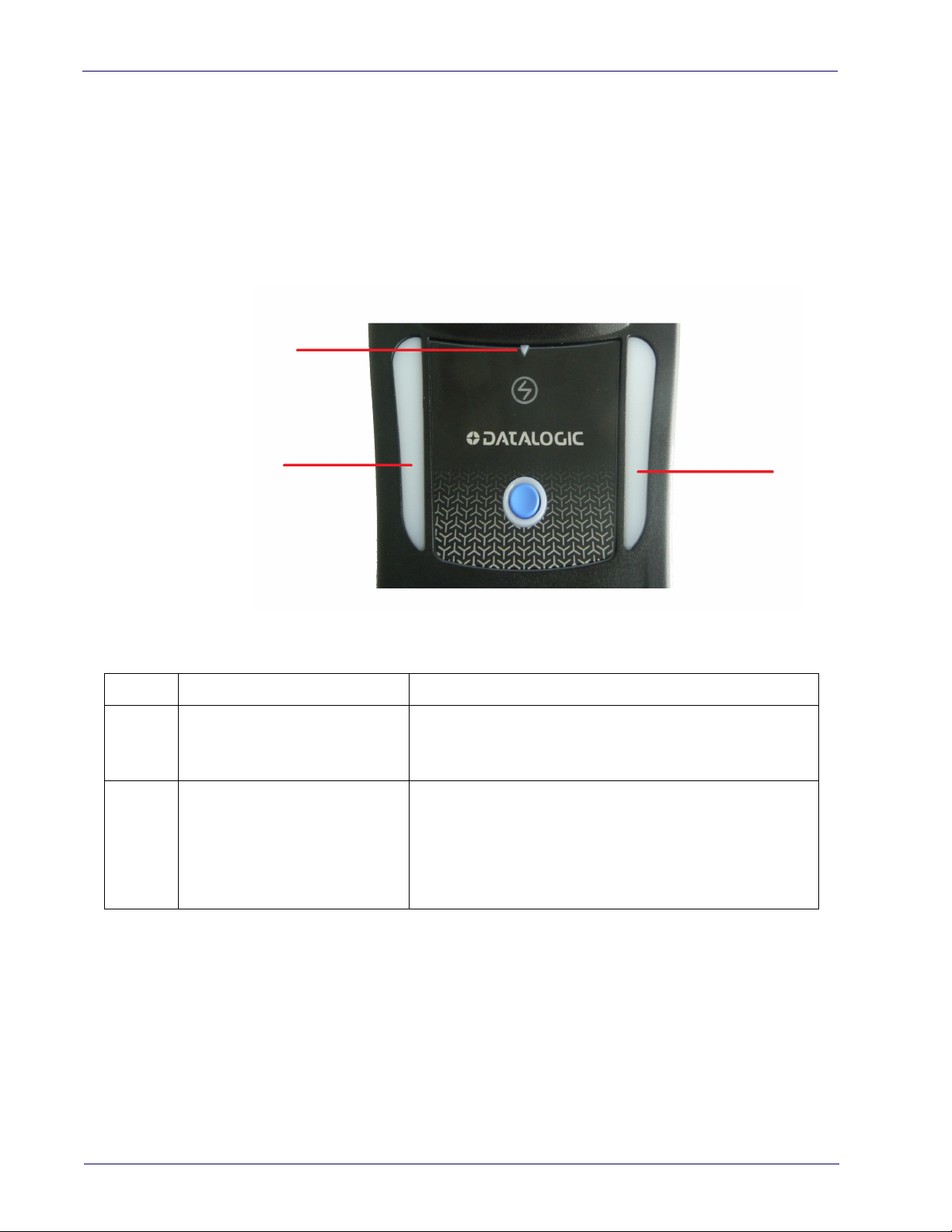
1
2
2
Using the WLC4090 Radio Base
Radio Base LEDs
LEDs on the Gryphon Base provide information about the Base as well as battery charging
status, as shown in Figure
Figure 2 - Gryphon Base LEDs
2
Table 1 - Radio Base LEDs
LED STATUS
Green On = Base is powered
1 Power on / Data
2 Charging
The button can be used to force device connection
and for paging the scanner when it is activated. Refer to the Gryphon I GBT/GM4500
Product Reference Guide (PRG) for a more detailed explanation.
Green Blinking = Base receives data and commands
from the
Green ON = the battery is completely
charged
Green fading = battery level 51 to 99%
Amber fading = battery level 1 to 50%
Red fading = pre-charge
Host or the Reader
via the Datalogic Aladdin Software tool
4 Gryphon™ I GD/GBT/GM4500
Page 15
Battery Safety
To install, charge and/or perform any other action on the battery, follow the instructions
in this manual.
WARNING
WARNING
Battery Safety
Do not discharge the battery using any device except for the scanner. When
the battery is used in devices other than the designated product, it may damage the battery or reduce its life expectancy. If
current to flow, it may cause the battery to become hot, explode or ignite and
cause serious injury.
Lithium-ion battery packs may get hot, explode or ignite an
injury if exposed to abusive conditions. Be sure to follow the safety warnings
listed on the following page.
•Do not place the battery pack in fire or heat.
•Do not connect the positive terminal and negative termi
pack to each other with any metal object (such as wire).
•Do not carry or store the battery pack together with metal objects.
•Do not pierce the battery pack with nails, strike it with a
it or otherwise subject it to strong impacts or shocks.
•Do not solder directly onto the battery
•Do not expose the battery pack to liquids, or allow the battery to get wet.
•Do not apply voltages to the battery pack
the device causes an abnormal
d cause serious
nal of the battery
hammer, step on
pack.
contacts.
WARNING
CAUTION
CAUTION
CAUTION
In the event the battery pack leaks and the fluid gets into your eye, do not rub
e eye. Rinse well with water and immediately seek medical care. If left
th
untreated, the battery fluid could cause damage to the eye
Always charge the battery at 32° – 104°F (0° - 40°C) temperature range.
Use only the authorized power supplies, battery
supplied by your Datalogic reseller. The use of any other power supplies can
damage the device and void your warranty.
Do not disassemble or modify the battery. The battery contains safety and
tion devices, which, if damaged, may cause the battery to generate
protec
heat, explode or ignite.
Do not place the battery in or near fire, on stoves or other high temperature
locations.
Do not place the battery in direct sunlight, or use or store the battery inside
cars in hot weather. Doing so may cause the battery to generate heat, explode
or ignite. Using the battery in this manner may also result in a loss of performance and a shortened li
Do not place the battery in microwave ovens, high-pressure containers or on
induction cookware.
Immediately discontinue use of the battery if, while using, charging or storing
the battery, the battery emits an unusual smell, feels hot, changes color or
shape, or appears abnormal in any other way.
Do not replace the battery pack when the device is turned on.
Do not remove or damage the battery pack’s label.
Do not use the battery pack if it is damaged in any part.
Battery pack usage by children
fe expectancy.
should be supervised.
pack, chargers, and docks
Product Reference Guide 5
Page 16

Introduction
As with other battery types, Lithium-Ion (LI) batteries will lose capacity over time. Capacity
deterioration is noticeable after one year of service whether the battery is in use or not. It
is difficult to precisely predict the finite life of a LI battery, but cell manufacturers rate
them at 500 charge cycles. In other words, the batteries should be expected to take 500
full discharge/charge cycles before needing replacement. This number is higher if partial
discharging/recharging is adhered to rather than full/deep discharging
Storage of batteries for long time at fully charged status or at fully discharged status should be avoided.
CAUTION
Only in case of long storage, to avoid deep discharge of the battery it is recommended to partially recharge the battery every three months to keep the
charge status at a medium level.
CAUTION
As a reference, run a fast recharge for
unused products to avoid any performance deterioration of the cell.
20 minutes every three months on
The useful life of LI batteries depends on usage and number of charges, etc., after which
they should be removed from service, especially in mission critical applications. Do not
continue to use a battery showing excessive loss of capacity, it should be properly recycled
/ disposed of and replaced.
Collect and recycle waste batteries sepa
rately from the device to comply with European
Directive 2006/66/EC, 2011/65/EU, 2002/96/EC and 2012/19/EU and subsequent modifications, US and China regulatory and other l
aws and regulations about the environment.
6 Gryphon™ I GD/GBT/GM4500
Page 17

Programming the Reader
Configuration Methods
Programming Bar Codes
The reader is factory-configured with a standard set of default features. After
scanning the interface bar code, you can select other options and customize
your reader through use of the instructions and programming bar code labels
available in the corresponding features section for your interface. Customizable
settings for many features are found in
page 33.
Some programming labels, like
only the scan of the single label to enact the change. Most, however, require the
read
er to be placed in Programming Mode prior to scanning them. Scan an
ENTER/EXIT bar code once to enter Programming Mode. Once the reader is in
Programming Mode, scan a number of parameter settings before scanning the
ENTER/EXIT bar code a second time, which will then accept your changes, exit
Programming Mode and return the reader to normal operation.
"Configuration Parameters"
"Restore Custom Defaults"
Programming the Reader
starting on
on page 27, require
There are some exceptions to the typical programming sequence described
above. Please read the description and setting instructions carefully when
configuring each programmable feature.
Datalogic Aladdin™
Datalogic Aladdin™ is a multi-platform utility program providing a quick and
user-friendly configuration method via the RS-232/USB-COM interface. Aladdin is available on the CD-ROM provided wi
Datalogic website. Aladdin allows you to program the reader by selecting configuration commands through a user-friendly graphical interface running on a
PC. Th
interface, or they can be printed as bar codes to be scanned.
Aladdin also provides the ability to perform a software upgrade for the connected device (see the Datalogic Aladdin™ Help On-Line for more details).
ese commands are sent to the reader over the selected communication
th your product, and also from the
Product Reference Guide 7
Page 18

Introduction
NOTES
8 Gryphon™ I GD/GBT/GM4500
Page 19

Unpacking
Check carefully to ensure the scanner and any cables or accessories ordered are
present and undamaged. If any damage occurred during shipment, contact
Technical Support on page 2.
KEEP THE PACKAGING. Should the unit ever require service, it should be
re
turned in its original shipping container.
Setting Up the Scanner
Depending on whether you are using a Corded or Wireless version of the Gryphon, follow the steps provided in this section to connect and get your scanner
up a
nd communicating with its host:
1. Connect the Interface Cable to the scanner or to the Base Station as shown
Figure 3. To disconnect the cable, insert a paper clip or
in
into the opening shown.
Chapter 2
Setup
similar object
2. Connect the other end to the Host (see the next section,
face on page 10
3. Modify "
are needed from factory settings).
NOTE
r
Customizing Configuration Settings" on page 34
and Figure 4).
(only if modifications
According to Regulation for shipping
products and their spare battery packs parts are shipped with a very low
residual charge (low state of charge).
Hence the needs:
• that a new product must be fully rech
and
• that battery packs of the stocked prod
tery pack parts must be periodically
WLC4090 cradle powered up with a 12V Datalogic AC/DC adapter (cod.
8-0935) for at least 30 minutes each 3 months.
Li-Ion based battery packs, the
arged before starting to use it
ucts GBT/GM45 and spare bat-
recharged : for instance by using a
Connect Host Inter-
Product Reference Guide 9
Page 20
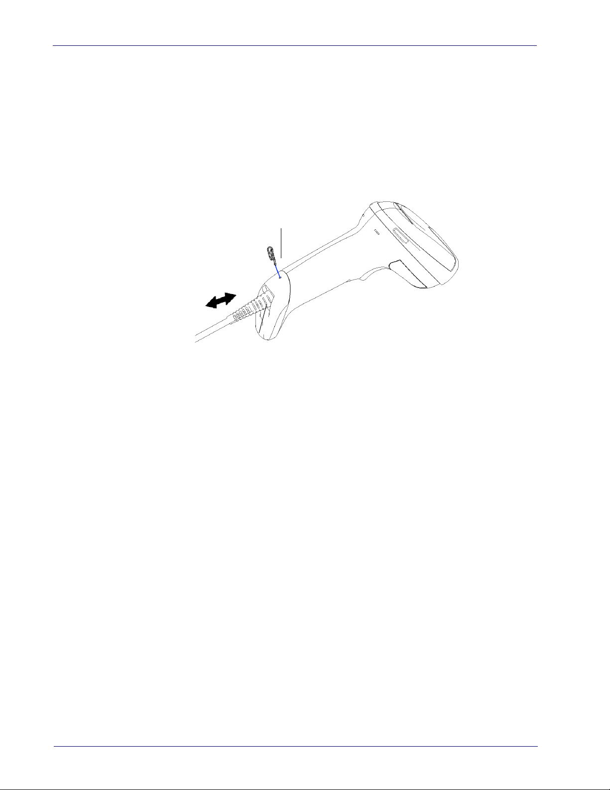
Setup
Cable Connector
Paper clip
Connect Host Interface
The scanner kit you ordered to match your interface should provide a compatible cable for your installation. If this is not so, contact
The scanner can communicate using the interfaces illustrated below.
For corded versions, connect the reader cable by inserting the cable into the
ha
ndle as shown in the following Figure. To remove it, insert a paper clip into
the release aperture, then unplug the cable.
Technical Support
.
Figure 3
. Cable Connection/Disconnection at the Scanner
RS-232 Serial Connection
Turn off power to the terminal/PC and connect the scanner to the terminal/PC
serial port via the RS-232 cable as shown in Figure 4. If the terminal will not
support POT (Power Off the Terminal) to supply sc
approved power supply (AC Adapter). Plug the AC Adapter barrel connector into
the socket on the RS-232 cable connector and the AC Adapter plug into a standard power outlet.
anner power, use the
10 Gryphon™ I GD/GBT/GM4500
RS-232:
RS-232 host.
RS-232 OPOS:
Keyboard Wedge Connection
The Keyboard Wedge cable has a ‘Y’ connection from the scanner. Connect the
female to the male end from the keyboard and the remaining end at the keyboard port at the terminal/PC.
Keyboard Wedge (KBW) :
scanned data as keystrokes and supports several international keyboards (for
the Windows
USB Connection
Connect the scanner to a USB port on the terminal/PC using the correct USB
cable for the interface type you ordered.
USB :
interface types by scanning the appropriate interface type bar codes available in
this manual. The default interface is USB-KBD, or RS-232-STD.
The scanner can communicate with a standard or Wincor-Nixdorf (W-N)
This interface is used for OPOS/UPOS/JavaPOS systems.
When connected using this interface, the host interprets
®
environment). See
Select to communicate either by USB OEM, USB COM STD, or USB Keyboard
"Country Mode"
on page 56 for a full listing.
Page 21
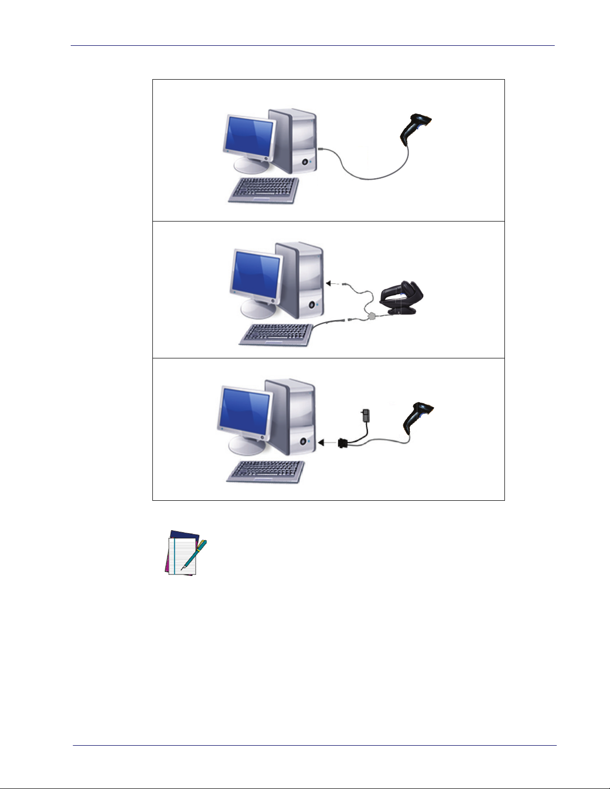
Figure 4. Connection to the Host
USB
WEDGE
RS-232
Setting Up the Scanner
Specific cables are required for connection to different hosts. The connections illustrated in Figure 4 are examples only. Actual connectors may vary
from those illustrated, but the steps to con
nect the scanner remain the
same.
NOTE
Product Reference Guide 11
Page 22
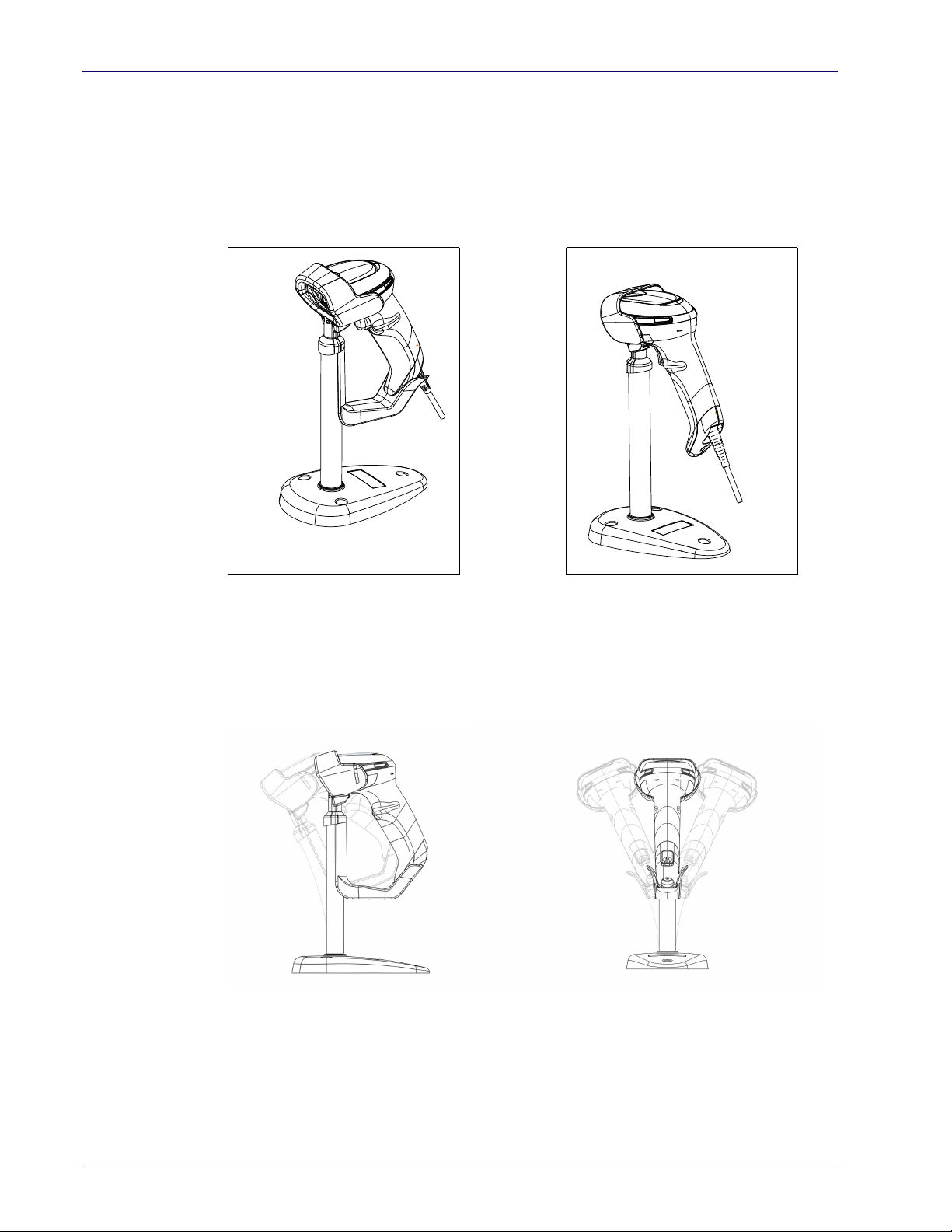
Setup
Stand Installation
Hands-Free Stand/Holder
An accessory is available which holds the reader (except those with integrated
stand) at a convenient angle, allowing hands free scanning of items.
It can also be used as a holder. The holder “cup” can be positioned in any of the
angles shown in the figure below. The reader automatically recognizes the
insertion and changes its Scan Mode to allow the user to operate in hands-free
mode.
Figure 5. Adjusting the Stand Arm
12 Gryphon™ I GD/GBT/GM4500
Page 23

Setting Up the Reader
Follow the steps below to connect and get your reader up and communicating
with its host.
1. Configure the Base Station starting on page 18.
2. Link to the Base Station on page 28.
3. Select the Interface Type on page 30.
Setting Up the Reader
NOTE
According to recent modification of Regulati
battery packs, the products and their spare battery packs parts are shipped
with a very low residual charge (low state of charge).
Hence the needs
* that a new product must be fully rech
and
* that battery packs of the stocked
pack parts must be periodically recharged: for instance by using a WLC4090
cradle powered up with a 12V Datalogic AC/DC adapter (cod.8-0935) for at
least 30 minutes each 3 months.
products GBT/GM45 and spare battery
on for shipping Li-Ion based
arged before starting to use it.
Product Reference Guide 13
Page 24

Setup
Positioning the Base Station
The base station/charger may be set up in desk application to hold the reader
in three different positions, either a horizontal or standing or vertical position,
in order to provide the most comfortable use depending on the needs.
Base Station Positions and related clips to be used
Figure 6 - Horizontal Position
This position is preferred, unless a different specific positioning is required, for
its outmost ease of insertion as well as the minimum effort and attention
required to customer when docking the scanner.
Figure 7 - Presentation Position
This position is preferred if the scanner is to be used in stand mode and not
needed to be often removed from base station.
14 Gryphon™ I GD/GBT/GM4500
Page 25
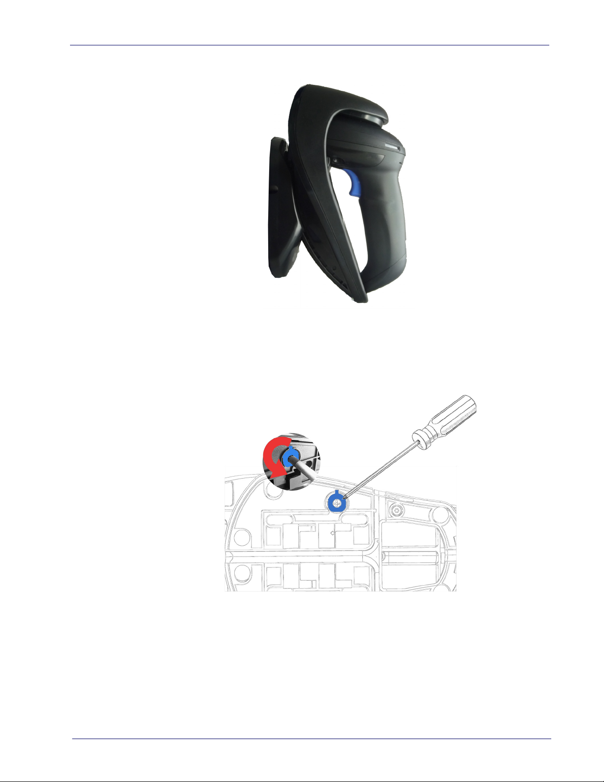
Figure 8 - Vertical Position
Setting Up the Reader
This position is preferred when lack of room on the desktop recommends the
scanner to be left vertical during recharging.
1. Insert the appropriate parts for the desired base st
2. Release the screw situated on the bottom of the cradle's base (the screw
will be kept
in position by the blue ring).
ation position.
Product Reference Guide 15
Page 26
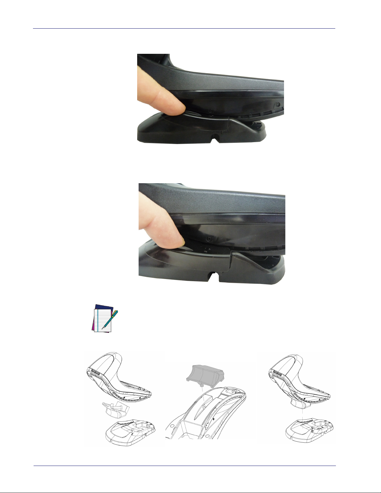
Setup
3. Using your thumbs, push open the plastic tabs on the bottom of the base
to free the wing holders.
4. The stand can now be repositioned in either horizontal or standing position.
To improve the robustness (against accidental falls) of the cradle in Presentation Position, it is suggested to add the
illustrated below.
NOTE
Shock Absorber addendum as
16 Gryphon™ I GD/GBT/GM4500
Page 27
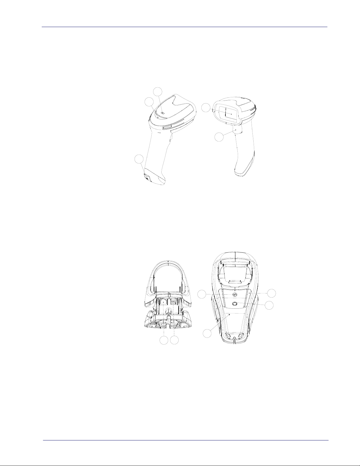
Reader, Cradle and LEDs Description
1
2
3
4
5
5
6
1
2
3
4
LEDs on the gun provide information about the battery charging status as well
as data transmission.
Figure 9- Gryphon Base LEDs
Reader, Cradle and LEDs Description
1 Scan Window 4 Good Read LED
2 Trigger 5 USB Port
3 Battery & Recharge LED
1 Service Button 4 Cable Release Hole
2 Power LED 5 Communicatioin Port
3 Recharge LED 6 Aux Power Port
Product Reference Guide 17
Page 28
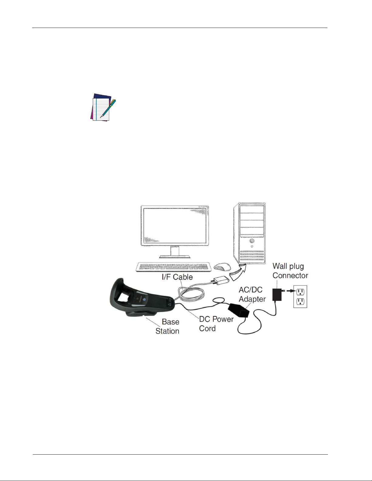
Setup
Connecting the Base Station
The following figure shows how to connect the Base Station to a terminal, PC or
other host device. Turn off the host before connection and consult the manual
for that equipment (if necessary) before proceeding. Connect the interface
cable before applying power to the Base Station.
wered by the Terminal. When
NOTE
The Gryphon GBT/GM4500 can also be Po
powered by the Terminal, the battery charger is automatically set as Slow
charge.
For some specific interfaces or hosts or lengths of cable, the use of an external power supply is recommended for full recharging capability (see "Technical Specifications" on page 39 for more details).
Base Station Connection and Routing
Fully insert the Power Cable and Interface (I/F) Cable connectors into their
respective ports in the underside of the Base Station. Then connect to an AC
Adapter, and plug the AC power cord into the (wall) outlet.
Figure 10 - Connecting the Base Station
18 Gryphon™ I GD/GBT/GM4500
Page 29
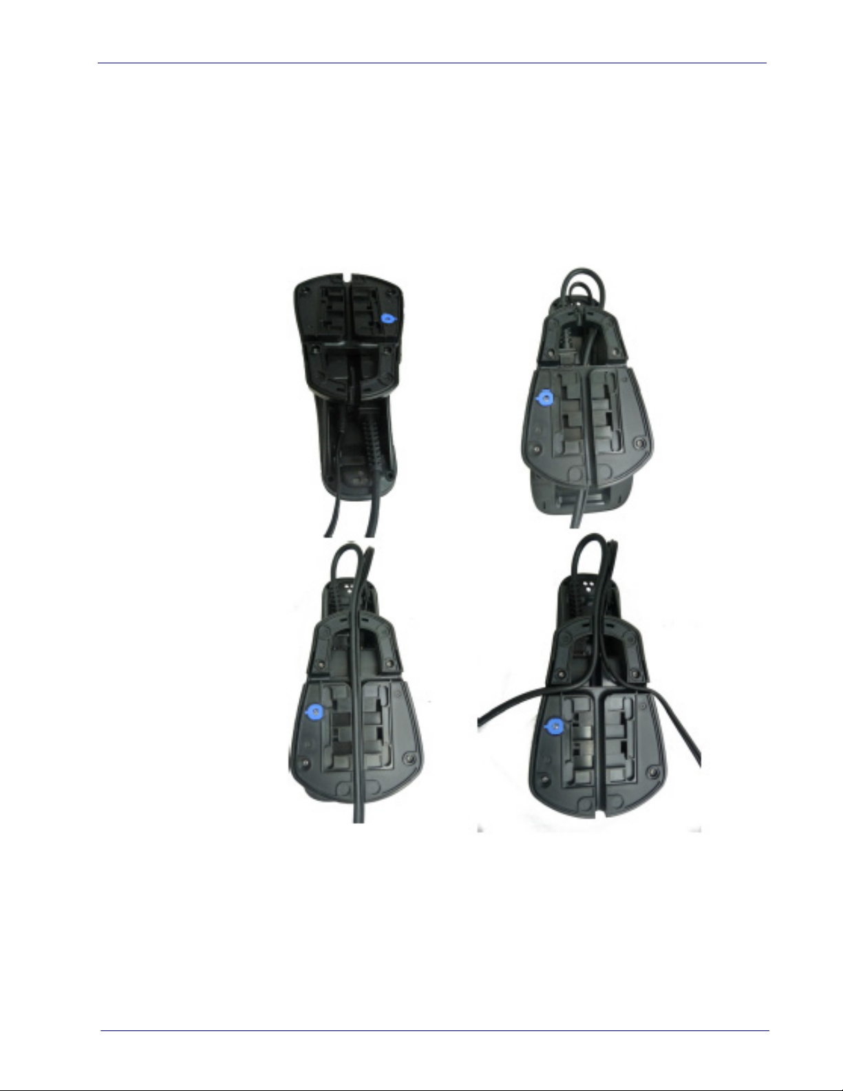
Securing the DC Power Cord (Optional)
The DC power cord for the adapter can be secured to the bottom of the base in
order to maximize the mechanical retention of the cable itself. The routing of
the power cord can be changed to accommodate base station positioning: horizontal, stand or wall mount. The cables can
the Base Station, or fed directly out the back of the Base Station, as shown in
the figure below.
Figure 11 - Options for routing the DC cord
Connecting the Base Station
be looped around to the front of
Product Reference Guide 19
Page 30
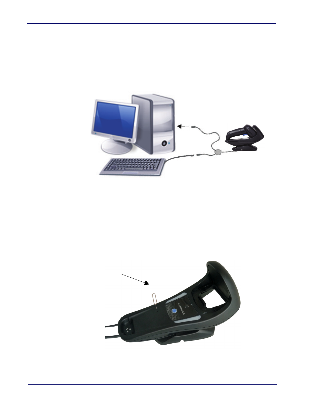
Setup
Insert Paper
Clip
Host Connection
Verify before connection that the reader’s cable type is compatible with your
host equipment.
Most connections plug directly into the host device as shown in the figure
be
low. Keyboard Wedge interface cables have a ‘Y’ connection where its female
end mates with the male end of the cable from the keyboard and the remaining
end at the keyboard port on the terminal/PC.
Figure 12 - Connecting to the Host
Power Connection
Plug the AC Adapter into an approved AC wall socket with the cable facing
downwards (as shown in Figure 5) to prevent undue strain on the socket.
Disconnecting the Cable
To detach the cable, insert a paper clip or similar object into the hole on the
base, as shown.
Figure 13 - Disconnecting the Cable
20 Gryphon™ I GD/GBT/GM4500
Page 31

System and Network Layouts
HOST
GRYPHON™
CRADLE
HOST
CRADLE
GRYPHON™
Stand Alone Layouts
Figure 14 - Single Reader Layout
System and Network Layouts
Figure 15 - Multiple Reader Layout
In stand alone systems, each cradle is connected to a single Host.
Product Reference Guide 21
Page 32

Setup
Figure 16 - Multiple Stand Alone Layouts
Many stand alone connections can operate in the same physical area without
interference, provided all readers and cradles in the system have different
addresses.
Using the GBT/GM4500 Scanner
Scanner LEDs
Specific LEDs on the Gryphon Scanner provide information about: good reading
result (3GL), battery status and charging status (with micro USB only). The Battery Status information can be easily retrieved by double-tapping
gers on top of the head of the scanner. The following table explains the main
co
lors' combinations provided by the Battery Status LED.
Table 2 - Battery LED
COLOR STATUS
Blinking color
(1s ON - 1s OFF)
Solid Green
(charge = 100%)
Solid color
(3s time-out)
Green (charge = 50% - 99%)
Red (charge less than 1%)
Scanner is unusable until 1% is reached
NOTE:
It goes OF
Green (charge = 50% - 100%)
Amber (charge = 2% - 50%)
Red blinking (charge less than 2%)
F when Scanner's unplugged Charge Complete through
Charge in Progress through
micro USB
micro USB
Battery Status
with your fin-
22 Gryphon™ I GD/GBT/GM4500
Page 33

Using the WLC4090 Radio Base
2
2
1
Radio Base LEDs
LEDs on the Gryphon Base provide information about the Base as well as battery
charging status, as shown in the figure below.
Figure 17 - Gryphon Base LEDs
Using the WLC4090 Radio Base
Table 3 - Radio Base LEDs
LED STATUS
1 Power on / Data Green On = Base is powered
Green Blinking = Base receives data and commands from the
Hos
t or the Reader.
2 Charging Green ON = the battery is completely charged
Green fading = battery level 51 to 99%
Amber fading = battery level 1 to 50%
Red fading = pre-charge
The button can be used to force device connection via the Datalogic Aladdin
Softwar
Gryphon I GBT/GM4500 Product Reference Guide (PRG) for a more detailed
expl
e tool and for paging the scanner when it is activated. Refer to the
anation.
Product Reference Guide 23
Page 34

Setup
Replacing the Battery Pack
Before proceeding, read “Battery Safety” on the preceding pages. Datal
recommends annual replacement of rechargeable battery packs to ensure
maximum performance.
NOTE
Use the following procedure to change the reader’s battery:
1. With a narrow metallic object (i.e. a coin) or a screwdriver, unscrew the
ttery cover screw.
ba
ogic
24 Gryphon™ I GD/GBT/GM4500
Page 35

2. Extract the battery pack from its slot.
3. Insert the new battery in the same position.
Replacing the Battery Pack
4. Replace the battery holder cap, plug in the connector and return the contacts circuit to its prev
When inserting the new battery into the handl
ious location.
e, take care to position the
battery and the connector as described above.
NOTE
5. Insert the cover in the handle and screw it into place.
Product Reference Guide 25
Page 36

Setup
Using the Gryphon™ I GD/GBT/GM4500
The Gryphon™ I GD4500 normally functions by capturing and decoding codes.
The aiming system is activated on trigger pull and indicates the center of the
field of view which should be positioned over the bar code:
Aiming System
Relative Size and Location of Aiming System Pattern
2D Matrix Symbol
Linear Bar
26 Gryphon™ I GD/GBT/GM4500
Page 37

Using the Gryphon™ I GD/GBT/GM4500
A red beam illuminates the label. The field of view indicated by the aiming system will be smaller when the reader is closer to the bar code and larger when it
farther from the code. Symbologies with smaller bars or elements (mil size)
is
should be read closer to the unit. Symbologies with larger bars or elements (mil
size) should be read farther from the unit. If the aiming system is centered and
the entire bar code is within the aiming field, you will get a good read. Successful reading is signaled by an audible to
indicator.
ne plus a good-read green spot LED
Relative Size and Location of Green Spot
Product Reference Guide 27
Page 38

Setup
Linking the Reader
Link Datalogic Devices to Base
Before configuring the interface it is necessary to link the handheld with the
base.
To link the handheld and the base simply put it into the base. If the reader was
pre
viously linked to another base, you must first scan the Unlink bar code
before re-linking to the new base.
Unlink
Link Scanner as Serial Device to a Bluetooth Host
Use this procedure to let the scanner communicate with a Bluetooth host using
the Bluetooth Serial Port Profile (SPP).
1. If using a Bluetooth adapter on the host
with the adapter.
2. Scan the Link to Host in SPP mode label below
to the host device.
3. Use the Bluetooth manager of the host device to “Discover new devices”
elect "GBT4500...". If you receive an error message, it may be neces-
and s
sary to change the security settings on either the host device or the scanner.
4. Use an RS-232 terminal program to see
nated by the Bluetooth manager of the host device.
Link to Host in SPP mode
device, install any driver provided
to make the scanner visible
incoming data on the port desig-
28 Gryphon™ I GD/GBT/GM4500
Page 39

Link Scanner as HID device to a Bluetooth host
Use this procedure to send data to a Bluetooth host using the Bluetooth HID
profile.
Power Off
1. If using a Bluetooth adapter on the host
with the adapter.
2. Scan the Link to Host in HID mode label below to make the scanner visible
to
the host device.
3. Use the Bluetooth manager of the host device to "Discover new devices"
nd select "GBT4500 …". If you receive an error message, it may be neces-
a
sary to change the security settings on either the host device or the scanner.
4. On the host device, open the program that is meant to receive the incoming data.
The data transmitted by the sca
typed using the keyboard of the host device.
nner will appear in the program as if it was
Link to Host in HID mode
device, install any driver provided
Power Off
The Gryphon I GBT4500 can be set up t
when connecting, by entering a Bluetooth passkey or a PIN code. If you want
to set the security level and authentication options suitable for your application, or when adding new equipment to a system that requires authenti-
NOTE
Scan the bar code below to shut off power to the handheld until the next trigger
pull.
cation or uses a custom security PIN
PowerOff
o authenticate the remote system
, please see the PRG for information.
Product Reference Guide 29
Page 40

Setup
Interface Selection
Upon completing the physical connection between the scanner and its host,
proceed directly to
programming for the interface type the scanner is connected to (for example:
RS
-232, Keyboard Wedge, USB, etc.) and scan the appropriate bar code in that
section to select your system’s correct interface type.
The scanner, depending upon the model, will support one of the following sets
f host interfaces:
o
• USB (Keyboard, COM, OEM)
• USB Composite (Keyboard + COM)
• USB HID POS
• USB Toshiba TEC
• RS-232 STD
• RS-232 WN
• RS232 OPOS
• Keyboard Wedge
"Configuring the Interface"
on page 30 for information and
• IBM46XX port 9b (a spec
• Datalogic Magellan Scanne
Configuring the Interface
Scan the programming bar code from the following section which selects the
appropriate interface type to match the system the scanner will be connected
to. Next, proceed to the corresponding chapter in this manual (also listed in the
table) to configure any desired settings and features associated with that interface.
Unlike some other programming featur
you scan only one programming bar code label. DO NOT scan an ENTER/EXIT bar code
prior to scanning an interface selection bar code. Some interfaces require the scanner
to start in the disabled state when powered up. If additional scanner configuration is
NOTE
desired while in this state, pull the trigger and hold for 5 seconds. The scanner will
change to a state that allows programming with bar codes.
ific cable's required)
rs' specific interface
es and options, interface selections require that
30 Gryphon™ I GD/GBT/GM4500
Page 41

Table 4. Available Interfaces
Interface Selection
RS-232
RS-232 standard interface
$P,HA12,P
Select RS232-WN
RS-232 for use with OPOS/UPOS/JavaPOS
$P,HA47,P
FEATURES
$P,HA05,P
Select RS232-STD
RS-232 Wincor-Nixdorf
$P,HA13,P
Select RS-232 OPOS
USB Com to simulate RS-232 standard interface
Select USB-COM-STD
USB-OEM FEATURES
USB-OEM
(can be used for OPOS/UPOS/JavaPOS)
a. Download the correct USB Com driver from www.datalogic.com
a
$P,HA45,P
Set USB-OEM
Interface
Features
starting on
Select USB-OEM
page 87
Product Reference Guide 31
Page 42

Setup
USB-COMPOSITE
USB-Composite
(combines USB-KBD emulation and USB-COM)
OTHER INTERFACES
Select IBM46xx Port 9b
USB HID POS
FEATURES
$P,HA45,P
Select USB-Composite
IBM46xx Port 9b
Select USB Toshiba TEC
Datalogic Magellan Scanners'
specific interface
Select USB HID POS
USB Toshiba TEC
Select Datalogic Magellan Scanners'
specific interface
32 Gryphon™ I GD/GBT/GM4500
Page 43

Interface Selection
KEYBOARD
AT, PS/2 25-286, 30-286, 50, 50Z, 60, 70, 80, 90
& 95 w/Standard Key Encoding
$P,HA11,P
Select KBD-AT-NK
AT, PS/2 25-286, 30-286, 50, 50Z, 60, 70, 80, 90
& 9
5 w/Alternate Key
$P,HA10,P
$P,HA29,P
Select KBD-AT
Keyboard Wedge for IBM AT PS2 with standard
key encoding but without external keyboard
$P,HA26,P
Select KBD-AT-ALT
Keyboard Wedge for IBM AT PS2 with alternate key
encoding but wi
thout external keyboard
FEATURES
Set KEYBOARD
WEDGE
Interface
Features
starting on
page 55
Select KBD-AT-ALT-NK
USB Keyboard with standard key encoding
$P,HA2B,P
Select USB Alternate Keyboard
$P,HA35,P
Select USB Keyboard
USB Keyboard with alternate key encoding
Product Reference Guide 33
Page 44

Setup
Customizing Configuration Settings
Using the Programming Bar Codes
This manual contains feature descriptions and bar codes which allow you to
reconfigure your scanner. Some programming bar code labels, like
Product Configuration to Defaults"
label to enact the change. Most o
ever, require the scanner to be placed
them. Scan an ENTER/EXIT bar code once to enter Programming Mode. Once
the scanner is in Programming Mode, you can scan a number of parameter settings before scanning the ENTER/EXIT bar
accept your changes, exit Programming Mode and return the scanner to normal
operation.
on page 35, require only the scan of that single
f the programming labels in this manual, how-
"Resetting the
in Programming Mode prior to scanning
code a second time, which will then
There are some exceptions to the typ
described above. Please read the description and setting instructions
carefully when configuring each given programmable feature.
NOTE
ical programming sequence
Datalogic Aladdin™ Utility
Programming can alternatively be performed using the Datalogic Aladdin™
Configuration application which is available for free download from the Datalogic website listed on the back cover of this manual. This multi-platform utility
ogram allows device configuration using a PC. It communicates to the device
pr
using a serial or USB cable and can also create configuration bar codes to print.
Datalogic Aladdin™ is a multi-platform utility program providing a quick and
use
r-friendly configuration method via the RS-232/USB-COM interface. The
Aladdin utility is available on the Datalogic website. Aladdin allows you to program the scanner by selecting configuration commands through a user-friendly
ical interface running on a PC. These commands are sent to the scanner
graph
over the selected communication interface, or they can be printed as bar codes
to be scanned.
Aladdin also provides the ability to perform a software upgrade for the connected device (see the Datalogic Aladdin™ Help On-Line for more details).
34 Gryphon™ I GD/GBT/GM4500
Page 45

Interface Settings
Transmit Software Version
Restore Custom Default Configuration
The scanner is typically factory-configured with a set of default features standard
to the interface type you ordered. See
Global Interface Features, starting on page 39
interface types. If your installation requires
you can select other options through use of the instructions and programming bar
codes available in the appropriate section for your interface.
RS-232 ONLY INTERFACE
•
• RS-232/USB-COM INTERFACES
• RS232 OPOS on page 30
• USB Composite (COM + Keyboard) on page 30
• KEYBOARD INTERFACE
• USB-OEM INTERFACE
Configuring Other Features
If your installation requires different programming than the standard factory
default settings, the following sections of this manual allow configuration of
non-interface-specific settings you might require:
Configuration Using Bar Codes: General Features includes programming for scan-
ning, speaker and LED indicators and other such universal settings.
Reading Parameters: Reading Parameters include programming for scanning,
speaker and LED indicators and other universal settings.
1D Symbologies: Includes options concerning the bar code label types (symbolo-
gies). These settings allow you to enable/disable symbologies, set label
ngths, require check digit, etc.
le
"Interface Selection"
on page 41
on page 55
on page 87
Customizing Configuration Settings
on page 30.
provides settings configurable by all
you to further customize your scanner,
on page 45
Software Version Transmission
The software version of the device can be transmitted over the RS-232, Key-
board and USB interfaces by sca
Resetting the Product Configuration to Defaults
If you aren't sure what programming options are in your scanner, or you've
changed some options and want to restore the Custom Default Configuration
that may have been saved in the scanner, scan the
uration
rently active interface.
bar code below. This will restore the custom configuration for the cur-
Custom defaults are based on the interface type. Configure the scanner for
the correct interface before scanning this label.
NOTE
nning the following label.
Restore Custom Default Config-
Product Reference Guide 35
Page 46

Setup
NOTES
36 Gryphon™ I GD/GBT/GM4500
Page 47

Chapter 3
Configuration Using Bar Codes
This and following sections provide programming bar codes to configure your
scanner by changing the default settings. For details about additional methods
of programming, see "
Customizing Configuration Settings" on page 34
.
You must first enable your scanner to rea
use this section. If you have not done this, go to
page 9
NOTE
Configuration Parameters
Once the scanner is set up, you can change the default parameters to meet your
application needs. Refer to "
35
for initial configuration in order to set the default values and select the
interface for your application.
The following configuration parameters are divided into logical groups, making
easy to find the desired function based on its reference group.
it
Interface Configuration:
• "RS-232 ONLY Interface" on page 41
• "RS-232/USB-COM Interfaces" on page 45
• "Keyboard Interface" on page 55
• "USB-OEM Interface" on page 87
Parameters common to all interface applications:
• "
Global Prefix/Suffix" on page 76
Data Format" on page 93
• "
ization of scanned data output.
Reading Parameters" on page 105
• "
cators status functioning.
d bar codes in order to
Setup, starting on
and complete the appropriate procedure.
Resetting the Product Configuration to Defaults" on page
offers advanced configuration options for custom-
control various operating modes and indi-
Symbology-specific parameters:
"1D Symbologies" on page 113
the programming bar codes necessary for configuring these features.
You must first enable your scanner to read bar codes in order to
use this section. If you have not done this, go to
page 9
NOTE
defines options for all symbologies and provides
Setup, starting on
and complete the appropriate procedure.
Product Reference Guide 37
Page 48

Enter/Exit Programming Mode
To program features:
1. Scan the ENTER/EXIT PROGRAMMING bar code, available at the top of each
programming page, when applicable.
2. Scan the bar code to set the desire
to cover unused bar codes on the page, and possibly the facing page, to
ensure that the scanner reads only the bar code you intend to scan.
3. If additional input parameters ar
scan the appropriate characters from the keypad.
d programming feature. You may need
e needed, go to
Appendix D, Keypad
, and
Additional information about many features can be found in the “References” chapter.
If you make a mistake before the last character, scan the CANCEL bar
code to ab
NOTE
4. Complete the programming sequence by scanning the ENTER/EXIT PROGRAMMING bar code to ex
For more detailed descriptions, programming information an
setting selected configuration items, see
the beginning.
ort and not save the entry string. You can then start again at
it Programming Mode.
d examples for
References, starting on page 273
.
38 Gryphon™ I GD/GBT/GM4500
Page 49

Global Interface Features
DEFAULT
The following interface features are configurable by all interface types. To set
features specific to your interface, turn to that section of this manual.
Enter/Exit Programming Mode
HOST COMMANDS — OBEY/IGNORE
USB SUSPEND MODE
on page 39
Host Commands — Obey/Ignore
This option specifies whether the scanner will obey or ignore host commands.
When set to ignore, the scanner will ignore all host commands except for those
necessary for:
•service mode
• flash programming mode
•keeping the inte
• transmission of labels.
rface active
on page 39
Host Commands = Obey
Host Commands = Ignore
USB Suspend Mode
This setting enables/disables the ability of the USB interface to enter suspend
mode.
DEFAULT
USB Suspend Mode = Enable
Product Reference Guide 39
Page 50

NOTES
40 Gryphon™ I GD/GBT/GM4500
Page 51

RS-232 ONLY Interface Enter/Exit Programming Mode
DEFAULT
RS-232 ONLY Interface
Use the programming bar codes in this chapter if modifications to the standard
RS-232 interface settings are necessary to meet your system’s requirements.
Additional settings which apply to both the RS-232 and USB interfaces are
available in
BAUD RATE on page 41 PARITY on page 43
DATA BITS on page 42 HANDSHAKING CONTROL on page 44
DATA BITS on page 42
RS-232 Standard Factory Settings
Reference Appendix B, for a listing of standard factory settings.
Baud Rate
Chapter 5, RS-232/USB-COM Interfaces.
Baud rate is the number of bits of data transmitted per second. Set the scanner's baud rate to match the baud rate se
improper baud rate setting, data may not reach the host correctly.
$CR2BA01
Baud Rate = 2400
$CR2BA03
tting of the host device. With an
$CR2BA00
Baud Rate = 1200
$CR2BA02
Baud Rate = 4800
Product Reference Guide 41
Baud Rate = 9600
Page 52

Enter/Exit Programming Mode Data Bits
Baud Rate (continued)
$CR2BA04
Baud Rate = 19,200
$CR2BA05
Baud Rate = 38,400
$CR2BA06
Baud Rate = 57,600
$CR2BA07
Data Bits
Baud Rate = 115,200
This parameter allows the reader to interface with devices requiring a 7-bit or
8-bit ASCII protocol for sending and receiving data.
$CR2ST00
7 Data Bits
$CR2ST01
DEFAULT
8 Data Bits
42 Gryphon™ I GD/GBT/GM4500
Page 53

RS-232 ONLY Interface Enter/Exit Programming Mode
Stop Bits
The stop bit(s) at the end of each transmitted character marks the end of transmission of one character and prepares the receiving device for the next character in the serial data stream. The number of stop bits selected (one or two)
pends on the number the receiving terminal is programmed to accommo-
de
date. Set the number of stop bits to
DEFAULT
$CR2ST01
2 Stop Bits
match host device requirements.
$CR2ST00
1 Stop Bit
Parity
This feature specifies parity required for sending and receiving data. A parity
check bit is the most significant bit of each ASCII coded character. Select the
parity type according to host device requirements.
• Select None when no parity bit
• Select Odd parity and the parity bit value i
ensure that an odd number of 1 bits are contained in the coded character.
• Select Even parity and the par
ensure that an even number of 1 bits are contained in the coded character.
is required.
s set to 0 or 1, based on data, to
ity bit value is set to 0 or 1, based on data, to
$CR2PA00
DEFAULT
Parity = None
$CR2PA01
Parity = Even
$CR2PA02
Parity = Odd
Product Reference Guide 43
Page 54

Enter/Exit Programming Mode Handshaking Control
Handshaking Control
The data interface consists of an RS-232 port designed to operate either with
or without the hardware handshaking lines, Request to Send (RTS), and Clear to
Send (CTS). Handshaking Control includes the following options:
• RTS — RTS is asserted during trans
• RTS/CTS — RTS is asserted during t
sions.
• RTS/XON/XOFF — RTS is asserted during transmissions.
XON and XOFF gate transmissions.
• RTS On/CTS — RTS is always asserted. CTS gates transmissions.
• RTS/CTS Scan Control — RTS is asserte
transmissions and controls enable and disable state of scanner.
DEFAULT
$CR2HC01
missions. CTS is ignored.
ransmissions. CTS gates transmis-
CTS is ignored.
d during transmissions. CTS gates
$CR2HC00
Handshaking Control = RTS
Handshaking Control = RTS/CTS
$CR2HC03
Handshaking Control = RTS On/CTS
$CR2HC02
Handshaking Control = RTS/XON/XOFF
$CR2HC04
Handshaking Control = RTS/CTS Scan Control
44 Gryphon™ I GD/GBT/GM4500
Page 55

RS-232/USB-COM Interfaces
The programming bar codes in this chapter allow modifications to the standard
RS-232 and USB-Com interfaces.
STAND AR D FACTORY SETTINGS on page 45
INTERCHARACTER DELAY on page 46
BEEP ON ASCII BEL on page 47
BEEP ON NOT ON FILE on page 47
ACK NAK OPTIONS on page 48
ACK CHARACTER on page 49
NAK CHARACTER on page 49
ACK NAK TIMEOUT VALUE on page 50
ACK NAK RETRY COUNT on page 51
ACK NAK ERROR HANDLING on page 52
INDICATE TRANSMISSION FAILURE on page 53
DISABLE CHARACTER on page 53
ENABLE CHARACTER on page 54
Standard Factory Settings
Reference Appendix B, for a listing of standard factory settings.
Product Reference Guide 45
Page 56

Enter/Exit Programming Mode Intercharacter Delay
00 = No Intercharacter Delay
Intercharacter Delay
This parameter specifies the intercharacter delay between the end of one character and the beginning of the next. The delay can be set within a range of zero
) to 990 milliseconds in 10ms increments. A setting of zero specifies no
(0
delay. See
ming instructions.
"Label ID: Pre-loaded Sets" on
page 288 for more detailed program-
$CR2IC00
Intercharacter Delay = No Delay
$CR2IC
Select Intercharacter Delay Setting
Make a mistake? Scan the CANCEL bar code to abort and
not save the entry string. You can then start again at the
beginning.
DEFAULT
To configure this feature, scan the ENTER/EXIT bar code
above, then the bar code at left followed by digits from
the Alphanumeric characters in
representing your desired character(s). End by
pad
scanning the ENTER/EXIT bar code again.
CANCEL
Appendix D, Key-
~
46 Gryphon™ I GD/GBT/GM4500
Page 57

RS-232/USB-COM Interfaces Enter/Exit Programming Mode
DEFAULT
Beep On ASCII BEL
When this parameter is enabled, the scanner issues a beep when a <BEL> character is detected on the RS-232 serial l
attention to an illegal entry or other important event.
$CR2BB00
Beep On ASCII BEL = Disable
ine. <BEL> is issued to gain a user's
DEFAULT
$CR2BB01
Beep On ASCII BEL = Enable
Beep On Not on File
This option enables/disables the action of the scanner to sound a three beep
sequence upon receiving a Not-On-File (NOF) host command.
$CBPNF00
Beep On Not On File = Disable
$CBPNF01
Beep On Not On File = Enable
Product Reference Guide 47
Page 58

Enter/Exit Programming Mode ACK NAK Options
ACK NAK Options
This enables/disables the ability of the scanner to support the RS-232 ACK/
NAK protocol. When configured, the scanner and/or host sends an “ACK” when
it receives data properly, and sends “NAK” when the data is in error.
Options are:
•Disable
• Enable for label transmission — The scanner expects an ACK/NAK
response from the host when a label is sent.
• Enable for host-command acknowledge — The scanner will respond with
ACK/NAK when the host sends a command.
• Enable for label transmission and host-command acknowledge
$CR2AE00
DEFAULT
ACK/NAK Protocol = Disable ACK/NAK
$CR2AE01
ACK/NAK Protocol = Enable for label transmission
$CR2AE03
ACK/NAK Protocol = Enable for label transmission and host-
command acknowledge
$CR2AE02
ACK/NAK Protocol = Enable for host-command
acknowledge
48 Gryphon™ I GD/GBT/GM4500
Page 59

RS-232/USB-COM Interfaces Enter/Exit Programming Mode
0x06 ‘ACK’ Character
0x15 ‘NAK’ Character
ACK Character
This setting specifies an ASCII character or hex value to be used as the ACK
character. ASCII characters or any hex value from 0 to 0xFF can be selected. See
"ACK Character" on
Setting to previously defined characters such as XON, XOFF, or host commands conflicts with normal operation
not recognized when the option
NOTE
Select ACK Character Setting
Data Bits.
page 276 for more detailed programming instructions.
of these characters. 8-bit data is
Data Bits on page 42
has been set as 7
DEFAULT
NAK Character
This setting specifies an ASCII character or hex value to be used as the NAK
character. ASCII characters or any hex value from 0 to 0xFF can be selected. See
"NAK Character" on
Setting to previously defined characters such as XON, XOFF, or host commands conflicts with normal operation of th
recognized when the option
NOTE
Select NAK Character Setting
Bits.
page 277 for more detailed programming instructions.
DEFAULT
Make a mistake? Scan the CANCEL bar code to abort and
not save the entry string. You can then start again at the
beginning.
ese characters. 8-bit data is not
Data Bits on page 42
CANCEL
has been set as 7 Data
Product Reference Guide 49
Page 60

Enter/Exit Programming Mode ACK NAK Options
DEFAULT
01 ACK NAK Timeout value is 200ms
ACK NAK Timeout Value
This option specifies the amount of time the scanner waits for an ACK character
from the host following label transmission. The selectable timeout range is 200
milliseconds to 15,000ms (15 seconds) in 200ms increments. A selection of 0
disables the timeout. See
detailed programming instructions.
Select ACK NAK Timeout Value Setting
Make a mistake? Scan the CANCEL bar code to abort and
not save
beginning.
the entry string. You can then start again at the
"ACK NAK Timeout Value" on
To configure this feature, scan the ENTER/EXIT bar code
above, then the bar code at left followed by digits from
the Alphanumeric characters in
pad
representing your desired character(s). End by
scanning the ENTER/EXIT bar code again.
page 278 for more
Appendix D, Key-
CANCEL
50 Gryphon™ I GD/GBT/GM4500
Page 61

RS-232/USB-COM Interfaces Enter/Exit Programming Mode
003 = 3 Retries
ACK NAK Retry Count
This feature specifies the number of times the scanner retries a label transmission due to a retry condition. The selectable range is from 1 to 254 retries. A
lection of 0 disables the count, and a selection of 255 specifies unlimited
se
retries. See
ming instructions.
Select ACK NAK Retry Count Setting
Make a mistake? Scan the CANCEL bar code to abort and
not save
beginning.
the entry string. You can then start again at the
"ACK NAK Retry Count" on
page 279 for more detailed program-
To configure this feature, scan the ENTER/EXIT bar code
above, then the bar code at left followed by digits from
the Alphanumeric characters in
pad
representing your desired character(s). End by
scanning the ENTER/EXIT bar code again.
Appendix D, Key-
CANCEL
DEFAULT
Product Reference Guide 51
Page 62

Enter/Exit Programming Mode ACK NAK Options
ACK NAK Error Handling
This feature specifies the method the scanner uses to handle receive errors
detected while waiting for an ACK character from the host.
Options are:
• Ignore errors detected
• Process error as valid ACK character
• Process error as valid NAK character
$CR2EH00
DEFAULT
ACK NAK Error Handling = Ignore Errors Detected
$CR2EH01
ACK NAK Error Handling = Process Error
d ACK Character
as Vali
$CR2EH02
ACK NAK Error Handling = Process Error
Valid NAK Character
as
52 Gryphon™ I GD/GBT/GM4500
Page 63

RS-232/USB-COM Interfaces Enter/Exit Programming Mode
0x44 = Disable Character is ‘D’
Indicate Transmission Failure
This option enables/disables the scanner’s ability to sound an error beep to
indicate a transmission failure while in ACK/NAK mode
Indicate Transmission Failure = Disable Indication
$CR2TF01
.
$CR2TF00
DEFAULT
Indicate Transmission Failure = Enable Indication
Disable Character
Specifies the value of the RS-232 host command used to disable the scanner.
ASCII characters or any hex value from 0 to 0xFF can be selected. See "Disable
page 280 for more detailed programming instructions.
Character"
Select Disable Character Setting
on
Setting to previously defined characters such as XON, XOFF, or host commands conflicts with normal operation of these characters.
NOTE
DEFAULT
Make a mistake? Scan the CANCEL bar code to abort and
not save the entry string. You can then start again at the
beginning.
~
CANCEL
Product Reference Guide 53
Page 64

Enter/Exit Programming Mode Enable Character
0x45 = Enable Character is ‘E’
Enable Character
Specifies the value of the RS-232 host command used to enable the scanner.
ASCII characters or any hex value from 0 to 0xFF can be selected. See
page 281 for more detailed programming instructions
Character"
Setting to previously defined characters such as XON, XOFF, or host commands conflicts with normal operation of
NOTE
$CR2EC
Select Enable Character Setting
on
these characters.
"Enable
.
DEFAULT
Make a mistake? Scan the CANCEL bar code to abort and
not save the entry string. You can then start again at the
beginning.
~
CANCEL
54 Gryphon™ I GD/GBT/GM4500
Page 65

Keyboard Interface
Use the programming bar codes in this chapter to select options for USB Keyboard and Wedge Inter
factory settings. Information about control character emulation which applies
to keybo
ard interfaces is listed in
faces. Reference
COUNTRY MODE on page 56
CAPS LOCK STATE on page 79
NUMLOCK on page 79
KEYBOARD NUMERIC KEYPAD on page 80
KEYBOARD SEND CONTROL CHARACTERS on page 81
WEDGE QUIET INTERVAL on page 82
INTERCODE DELAY on page 84
USB KEYBOARD SPEED on page 85
Appendix B, for a listing of standard
Appendix E, Scancode Tables.
Product Reference Guide 55
Page 66

Enter/Exit Programming Mode Country Mode
Country Mode
This feature specifies the country/language supported by the keyboard.
The Country Mode setting is ignored if the interface uses alternate key encod-
ing.
Setup on PC to use ALT Universal
1. Open Registry Edit
2. Set EnableHexNumpad to 1 as follows:
3. Reset the PC.
56 Gryphon™ I GD/GBT/GM4500
Page 67

Keyboard Interface Enter/Exit Programming Mode
Setting Country Mode
$CKBCO00
DEFAULT
United States
$CKBCO01
French International (Belgian French)
$CKBCO02
United Kingdom
$CKBCO11
Danish
$CKBCO03
German
$CKBCO0E
French (France)
$CKBCO04
Italian
Product Reference Guide 57
Page 68

Enter/Exit Programming Mode Country Mode
Setting Country Mode (continued)
$CKBCO0F
Norwegian
$CKBCO09
Portuguese Portugal
$CKBCO0A
Spanish
$CKBCO0B
Swedish
$CKBCO14
Japanese ASCII
$CKBCO13
Swiss French
$CKBCO13
Hungarian
58 Gryphon™ I GD/GBT/GM4500
Page 69

Keyboard Interface Enter/Exit Programming Mode
Setting Country Mode (continued)
$CKBCO0F
Czech
$CKBCO09
SlovaK
$CKBCO0A
Romanian
$CKBCO0B
Croatian
$CKBCO14
Canadian French Win7
$CKBCO13
Polish_214
$CKBCO13
Lithuanian
Product Reference Guide 59
Page 70

Enter/Exit Programming Mode Country Mode
Setting Country Mode (continued)
$CKBCO0F
Vietnamese
$CKBCO09
Russian
$CKBCO0A
Arabic 101
$CKBCO0B
Chinese ASCII
$CKBCO14
Albanian
$CKBCO13
Thai-Kedmanee
$CKBCO13
Arabic 102
60 Gryphon™ I GD/GBT/GM4500
Page 71

Keyboard Interface Enter/Exit Programming Mode
Setting Country Mode (continued)
$CKBCO0F
Arabic 102 AZERTY
$CKBCO09
Azeri Cyrillic
$CKBCO0A
Azeri Latin
$CKBCO0B
Belarusian
$CKBCO14
Bosnian Latin
$CKBCO13
Bosnian Cyrillic
$CKBCO13
Bulgarian Cyrillic
Product Reference Guide 61
Page 72

Enter/Exit Programming Mode Country Mode
Setting Country Mode (continued)
$CKBCO0F
Bulgarian Latin
$CKBCO09
Canadian French (Legacy)
$CKBCO0A
Canadian Multilingual
$CKBCO0B
Chinese (Simplified)
$CKBCO14
Czech Programmers
$CKBCO13
Chinese (Traditional)
$CKBCO13
Czech QWERTY
62 Gryphon™ I GD/GBT/GM4500
Page 73

Keyboard Interface Enter/Exit Programming Mode
Setting Country Mode (continued)
$CKBCO0F
Dutch Netherland
$CKBCO09
Estonian
$CKBCO0A
Faeroese
$CKBCO0B
Finnish
$CKBCO14
French (Canada) 95/98
$CKBCO13
French (Canada) 2000/XP
$CKBCO13
Galician
Product Reference Guide 63
Page 74

Enter/Exit Programming Mode Country Mode
Setting Country Mode (continued)
$CKBCO0F
Greek
$CKBCO09
Greek Latin
$CKBCO0A
Greek Polytonic
$CKBCO0B
Greek220
$CKBCO14
Greek319
$CKBCO13
Greek220 Latin
$CKBCO13
Greek319 Latin
64 Gryphon™ I GD/GBT/GM4500
Page 75

Keyboard Interface Enter/Exit Programming Mode
Setting Country Mode (continued)
$CKBCO0F
Hebrew Israel
$CKBCO09
Hungarian_101KEY
$CKBCO0A
Icelandic
$CKBCO0B
Irish
$CKBCO14
Japanese (Shift-JIS)
$CKBCO13
Italian_142
$CKBCO13
Kazakh
Product Reference Guide 65
Page 76

Enter/Exit Programming Mode Country Mode
Setting Country Mode (continued)
$CKBCO0F
Korean (Hangul)
$CKBCO09
Korean ASCII
$CKBCO0A
Kyrgyz Cyrillic
$CKBCO0B
Latin America
$CKBCO14
Latvian QWERTY
$CKBCO13
Latvian
$CKBCO13
Lithuanian_IBM
66 Gryphon™ I GD/GBT/GM4500
Page 77

Keyboard Interface Enter/Exit Programming Mode
Setting Country Mode (continued)
$CKBCO0F
Macedonian -FYROM
$CKBCO09
Maltese_47KEY
$CKBCO0A
Mongolian-Cyrillic
$CKBCO0B
Polish Programmer
$CKBCO14
Portuguese Brazilian ABNT
$CKBCO13
Portuguese Brazil
$CKBCO13
Portuguese Brazilian ABNT2
Product Reference Guide 67
Page 78

Enter/Exit Programming Mode Country Mode
Setting Country Mode (continued)
$CKBCO0F
Romanian Legacy
$CKBCO09
Romanian Programmer
$CKBCO0A
Romanian Standard
$CKBCO0B
Russian Typewriter
$CKBCO14
Serbian Latin
$CKBCO13
Serbian Cyrillic
$CKBCO13
Slovak QWERTY
68 Gryphon™ I GD/GBT/GM4500
Page 79

Keyboard Interface Enter/Exit Programming Mode
Setting Country Mode (continued)
$CKBCO0F
Slovenian
$CKBCO09
Spanish Variation
$CKBCO0A
Swiss German
$CKBCO0B
Tatar
$CKBCO14
Turkish Q
$CKBCO13
Turkish F
$CKBCO13
Ukrainian
Product Reference Guide 69
Page 80

Enter/Exit Programming Mode Country Mode
Setting Country Mode (continued)
$CKBCO0F
US Dvorak
$CKBCO09
US Dvorak Left Hand
$CKBCO0A
US Dvorak Right Hand
$CKBCO0B
US English (Mac)
$$CKBCO62
US International
$CKBCO13
US English (North American)
$$CKBCO63
Uzbek Cyrillic
70 Gryphon™ I GD/GBT/GM4500
Page 81

Keyboard Interface Enter/Exit Programming Mode
Setting Encoding Type
.
$CKBCO00
DEFAULT
Don’t use encoding
$CKBCO01
UTF_8
$CKBCO02
Windows 874
$CKBCO11
Windows 932
$CKBCO03
Windows 949
$CKBCO0E
Windows 936
$CKBCO04
Windows 950
Product Reference Guide 71
Page 82

Enter/Exit Programming Mode Country Mode
Setting Encoding Type (continued)
$CKBCO03
Windows 1250
$CKBCO09
Windows 1251
$CKBCO0A
Windows 1252
$CKBCO0B
$CKBCO13
Windows 1254
$CKBCO13
Windows 1256
Windows 1253
$CKBCO14
Windows 1255
72 Gryphon™ I GD/GBT/GM4500
Page 83

Keyboard Interface Enter/Exit Programming Mode
Setting Encoding Type (continued)
$CKBCO0F
Windows 1257
$CKBCO09
Windows 1258
$CKBCO0A
Windows 20866
$CKBCO0B
ISO 8859-1
$CKBCO14
ISO 8859-3
$CKBCO13
ISO 8859-2
$CKBCO13
ISO 8859-4
Product Reference Guide 73
Page 84

Enter/Exit Programming Mode Country Mode
Setting Encoding Type (continued)
$CKBCO0F
ISO 8859-5
$CKBCO09
ISO 8859-6
$CKBCO0A
ISO 8859-7
$CKBCO0B
ISO 8859-8
$CKBCO14
ISO 8859-10
$CKBCO13
ISO 8859-9
$CKBCO13
ISO 8859-11
74 Gryphon™ I GD/GBT/GM4500
Page 85

Keyboard Interface Enter/Exit Programming Mode
Setting Encoding Type (continued)
$CKBCO0F
ISO 8859-13
$CKBCO09
ISO 8859-14
$CKBCO0A
ISO 8859-15
$CKBCO0B
ISO 8859-16
$CKBCO14
MS-DOS 737
$CKBCO13
MS-DOS 437
$CKBCO13
MS-DOS 775
Product Reference Guide 75
Page 86

Enter/Exit Programming Mode Country Mode
Setting Encoding Type (continued)
$CKBCO0F
MS-DOS 850
$CKBCO09
MS-DOS 852
$CKBCO0A
MS-DOS 855
$CKBCO0B
MS-DOS 857
$CKBCO14
MS-DOS 861
$CKBCO13
MS-DOS 860
$CKBCO13
MS-DOS 862
76 Gryphon™ I GD/GBT/GM4500
Page 87

Keyboard Interface Enter/Exit Programming Mode
Setting Encoding Type (continued)
$CKBCO0F
MS-DOS 863
$CKBCO09
MS-DOS 865
$CKBCO0A
MS-DOS 866
$CKBCO0B
MS-DOS 869
$CKBCO13
Mac CP10000
Product Reference Guide 77
Page 88

Enter/Exit Programming Mode Country Mode
DEFAULT
Setting ALT output type
This option specifies the encode type of ALT Mode when the scanner sends
Output Keyboard Data in Alt Mode. (Be aware that the scanner may switch automatically between ALT mode & Normal Keyboard Sca
some characters that are not present in the current Keyboard Country).
.
ALT Codepage: (use on non Unicode application: Notepad)
$CKBCO01
ALT Unicode: (use on Unicode application: Word)
ncode, to correctly display
$CKBCO00
$CKBCO02
ALT Universal: (Use for all)
78 Gryphon™ I GD/GBT/GM4500
Page 89

Keyboard Interface Enter/Exit Programming Mode
Caps Lock State
This option specifies the format in which the scanner sends character data. This
applies to Keyboard Wedge interfaces.
encoding keyboard is selected. This does not apply to USB Keyboard.
DEFAULT
$CKBCL01
Caps Lock State = Caps Lock ON
This does not apply when an alternate key
$CKBCL00
Caps Lock State = Caps Lock OFF
$CKBCL02
Numlock
Caps Lock State = AUTO Caps Lock Enable
This option specifies the setting of the Numbers Lock (Numlock) key while in
Keyboard Wedge interface. This only applies to alternate key encoding interfaces.
It does not apply to USB Keyboard.
$CKBNL00
DEFAULT
Numlock = Numlock key unchanged
$CKBNL01
Numlock = Numlock key toggled
Product Reference Guide 79
Page 90

Enter/Exit Programming Mode Keyboard Numeric Keypad
Keyboard Numeric Keypad
This feature specifies if numeric characters will be sent using the standard keys
or the numeric keypad
DEFAULT
$CKBKP01
Keyboard Numeric Keypad = Numeric Keypad
.
$CKBKP00
Keyboard Numeric Keypad = Standard Keys
80 Gryphon™ I GD/GBT/GM4500
Page 91

Keyboard Interface Enter/Exit Programming Mode
Keyboard Send Control Characters
This feature is used by the Keyboard Wedge and USB Keyboard interfaces. It
specifies how the scanner transmits ASCII control characters to the host. Reference
Appendix E, Scancode Tables for more information about control charac-
ters.
Options are as follows:
Send Ctrl+Key :
the format Ctrl+Key. Special keys are available in the range from 81H to A1.
Send Ctrl+Shift+Key :
in the format Ctrl+Shift+Keys.
Send Special Function Key :
the special function key mapping table (see "
Mode or USB-Keyboard Alt Mode" on page 340
are not in the normal ASCII set. A unique set is provided for each available
scancode set.
ASCII characters from 00H to 0x1FH inclusive are transmitted in
The behavior is the same as above, but control keys are sent
Send characters between 00H and 1FH according to
In
terface Type PC AT PS/2 Alt
). This is used to send keys that
$CKBSC00
DEFAULT
Keyboard Send Control Characters = Send Ctrl+Key
$CKBSC01
Keyboard Send Control Characters = Send Ctrl+Shift+Key
$CKBSC02
Keyboard Send Control Characters = Send Special Function
Key :
Product Reference Guide 81
Page 92

Enter/Exit Programming Mode Wedge Quiet Interval
10 = Quiet Interval of 100 ms
Wedge Quiet Interval
This option specifies the amount of time to look for keyboard activity before
the scanner breaks the keyboard connection in order to transmit data to host.
The selectable range for this feature is from 0 to 990ms in 10ms increments.
See
"Wedge Quiet Interval" on
instructions.
This feature applies ONLY to the Keyboard Wedge interface.
NOTE
page 282 for more detailed programming
$CKBQI
Select Wedge Quiet Interval Setting
Make a mistake? Scan the CANCEL bar code to abort and
not save the entry string. You can then start again at the
beginning.
To configure this feature, scan the ENTER/EXIT bar code
above, then the bar code at left followed by digits from the
Alphanumeric characters in
representing your desired char
the ENTER/EXIT bar code again.
DEFAULT
Appendix D, Keypad
acter(s). End by scanning
~
CANCEL
82 Gryphon™ I GD/GBT/GM4500
Page 93

Keyboard Interface Enter/Exit Programming Mode
00 = No Intercharacter Delay
Intercharacter Delay
This parameter specifies the intercharacter delay between the end of one character and the beginning of the next. The delay can be set within a range of zero
) to 990 milliseconds in 10ms increments. A setting of zero specifies no
(0
delay.
instructions.
See "Intercharacter Delay" on
page 283
for more detailed programming
$CR21C00
Intercharacter Delay = No Delay
$CR21C
Select Intercharacter Delay Setting
Make a mistake? Scan the CANCEL bar code to abort and not
save the entry string. You can then start again at the begin-
ning.
DEFAULT
To configure this feature, scan the ENTER/EXIT bar code
above, then the bar code at left followed by digits from the
Alphanumeric characters in
representing your desired char
the ENTER/EXIT bar code again.
Appendix D, Keypad
~
CANCEL
acter(s). End by scanning
Product Reference Guide 83
Page 94

Enter/Exit Programming Mode Intercode Delay
DEFAULT
00 = No Wedge Intercode Delay
Intercode Delay
Specifies the delay between labels transmitted to the host for this interface. The
selectable range for this feature is from 0 to 99 seconds. See
on page 284 for more detailed programming in
structions.
"Intercode Delay"
$CKBID
Set Intercode Delay
Make a mistake? Scan the CANCEL bar code to abort and
not save the entry string. You can then start again at the
beginning.
To configure this feature, scan the ENTER/EXIT bar code
above, then the bar code at left followed by digits from the
Alphanumeric characters in
representing your desired char
the ENTER/EXIT bar code again.
Appendix D, Keypad
acter(s). End by scanning
~
CANCEL
84 Gryphon™ I GD/GBT/GM4500
Page 95

Keyboard Interface Enter/Exit Programming Mode
USB Keyboard Speed
This option specifies the USB poll rate for a USB Keyboard.
This feature applies ONLY to the USB Keyboard interface.
NOTE
$CKBSP01
DEFAULT
USB Keyboard Speed = 1ms
$CKBSP02
USB Keyboard Speed = 2ms
$CKBSP03
$CKBSP05
USB Keyboard Speed = 5ms
$CKBSP0A
USB Keyboard Speed = 10ms
USB Keyboard Speed = 3ms
$CKBSP07
USB Keyboard Speed = 7ms
Product Reference Guide 85
Page 96

Keyboard Interface
USB Keyboard Numeric Keypad
This option Controls whether numeric characters will be sent using standard
keys or the numeric keypad.
DEFAULT
Standard Keys
Numeric Keypad
86 Gryphon™ I GD/GBT/GM4500
Page 97

USB-OEM Interface
INTRODUCTION on page 87
STA NDAR D FACTORY SETTINGS on page 87
USB-OEM DEVICE USAGE on page 88
USB-OEM INTERFACE OPTIONS on page 88
Introduction
Feature settings for USB interfaces differ depending upon which host type the
scanner will be connected with. Use the feature settings in this chapter to specifically configure for the USB-OEM interface. Other USB interfaces are included
n the appropriate chapter for their host type.
i
Standard Factory Settings
Reference Appendix B, for a listing of standard factory settings.
Product Reference Guide 87
Page 98

Enter/Exit Programming Mode USB-OEM Device Usage
DEFAULT
DEFAULT
USB-OEM Device Usage
The USB-OEM protocol allows for the scanner to be identified as one of two different types of bar code scanners. Depending on what other scanners you may
lready have connected to a USB-OEM POS, you may need to change this setting
a
to enable all devices to communicate.
Options are:
• Tabletop Scanner
• Handheld Scanner
It may be necessary to switch device usage when connecting two
scanners of the same type to a POS system.
NOTE
$CIBUT00
$CIBUT01
USB-OEM Device Usage = Handheld Scanner
USB-OEM Interface Options
This setting provides for an interface specific control mechanism.
Options are:
• Obey — Obey Scanner Configuration Host Commands
• Ignore — Ignore Scanner Configuration Host Commands
$CIFO102
USB-OEM Device Usage = Tabletop Scanner
$CIFO101
USB-OEM Interface Options = Obey
USB-OEM Interface Options = Ignore
88 Gryphon™ I GD/GBT/GM4500
Page 99

IBM 46XX Interface
Use the bar codes in this section to configure programmable features for available IBM 46XX interfaces.
Reference Appendix B, for a listing of standard factory settings..
46XX NUMBER OF HOST RESETS on page 72
TRANSMIT LABELS IN CODE 39 FORMAT on page 92
INTERFACE OPTIONS on page 92
Product Reference Guide 89
Page 100

Enter/Exit Programming Mode
DEFAULT
46xx Number of Host Resets
Specifies how many consecutive resets are processed before the reader starts a
five-second period to allow the user to enter Programming Mode and configure
the reader. The configurable range for this feature is 1 to 15 resets.
46xx Number of Host Resets = 2
46xx Number of Host Resets = 1
46xx Number of Host Resets = 4
46xx Number of Host Resets = 6
46xx Number of Host Resets = 3
46xx Number of Host Resets = 5
46xx Number of Host Resets = 7
90 Gryphon™ I GD/GBT/GM4500
 Loading...