

Page 1

Mobile Computer
User’s Manual
Page 2

Datalogic ADC S.r.l.
Via S. Vitalino, 13
40012 Lippo di Calderara di Reno
Bologna - Italy
Telephone: (+39) 051-3147011
Fax: (+39) 051-3147205
©2014 Datalogic ADC S.r.l.
An Unpublished Work - All rights reserved. No part of the contents of this documentation or
the procedures described therein may be reproduced or transmitted in any form or by any
means without prior written permission of Datalogic ADC, Inc. or its subsidiaries or affiliates
("Datalogic" or “Datalogic ADC”). Owners of Datalogic products are hereby granted a nonexclusive, revocable license to reproduce and transmit this documentation for the
purchaser's own internal business purposes. Purchaser shall not remove or alter any
proprietary notices, including copyright notices, contained in this documentation and shall
ensure that all notices appear on any reproductions of the documentation. Should future
revisions of this manual be published, you can acquire printed versions by contacting your
Datalogic representative. Electronic versions may either be downloadable from the Datalogic
website (www.datalogic.com) or provided on appropriate media. If you visit our website and
would like to make comments or suggestions about this or other Datalogic publications,
please let us know via the "Contact Datalogic" page.
Disclaimer
Datalogic has taken reasonable measures to provide information in this manual that is
complete and accurate, however, Datalogic reserves the right to change any specification at
any time without prior notice. Datalogic and the Datalogic logo are registered trademarks of
Datalogic S.p.A. in many countries, including the U.S.A. and the E.U.
Falcon and the Falcon logo are trademarks of Datalogic ADC S.r.l.
All other brand and product names may be trademarks of their respective owners.
Patents
Patent. See www.patents.datalogic.com for patent list.
This product is covered by one or more of the following patents:
Design patents: AU329643, EP001180673, USD622726, ZL200930383849.1
Utility patents: EP0789315B1, EP1128315B1, EP1396811B1, EP1413971B1, US5686716,
US5992740, US6412698, US6415978, US6454168, US6478224, US6513714, US6561427,
US6585157, US6808114, US6997385, US7108170, US7299975, US7387246.
Page 3

iii
CONTENTS
REFERENCES ............................................................................................ VI
Conventions .................................................................................................. vi
Reference Documentation ............................................................................ vi
Services and Support .................................................................................... vi
GENERAL VIEW ........................................................................................ VII
1 INTRODUCTION .......................................................................................... 1
1.1 Falcon X3+ Description ................................................................................. 1
1.2 Available Models ........................................................................................... 3
1.3 Package Contents ......................................................................................... 7
1.4 Inserting a MicroSD Card .............................................................................. 8
1.4.1 Removing the MicroSD Card ........................................................................ 9
1.5 Accessories ................................................................................................. 10
2 BATTERIES AND MAINTENANCE ........................................................... 12
2.1 Charging the Battery Pack .......................................................................... 12
2.2 Replacing the Battery Pack ......................................................................... 15
2.3 Cleaning the Mobile Computer .................................................................... 19
3 CONNECTIONS ......................................................................................... 20
3.1 USB Connection ......................................................................................... 20
3.2 Connection to USB Peripherals .................................................................. 22
3.3 RS232 Connection ...................................................................................... 24
3.4 WLAN Connection ...................................................................................... 25
3.5 WPAN Connections .................................................................................... 27
3.6 Wireless and Radio Frequencies Warnings ................................................ 28
4 USE AND FUNCTIONING .......................................................................... 30
4.1 Startup ........................................................................................................ 30
4.1.1 Using the Stylus .......................................................................................... 31
4.2 Windows Embedded Handheld Welcome Wizard ....................................... 32
4.3 Data Capture ............................................................................................... 33
4.3.1 Laser Data Capture ..................................................................................... 34
4.3.2 Imager Data Capture................................................................................... 36
4.4 Description of the Keys ............................................................................... 38
4.4.1 52-Key Alphanumeric Keyboard ................................................................. 38
4.4.2 52-Key Terminal Emulation 5250 Keyboard ................................................ 39
4.4.3 Numeric Keyboard ...................................................................................... 41
4.4.4 Resetting the Falcon X3+ ............................................................................ 43
4.5 Status Indicators ......................................................................................... 45
4.5.1 LED Status .................................................................................................. 45
4.5.2 Taskbar ....................................................................................................... 46
4.6 Settings ....................................................................................................... 47
Page 4

iv
4.6.1 Data Capture Configuration ........................................................................ 48
4.6.2 Buttons ........................................................................................................ 57
4.6.3 DL Buttons .................................................................................................. 58
4.6.4 Triggers ....................................................................................................... 60
4.6.5 Application Switcher .................................................................................... 61
4.6.6 Wireless Communications ........................................................................... 62
4.6.7 Stylus Calibration ........................................................................................ 67
4.6.8 Audio Settings ............................................................................................. 69
4.7 Connecting to Other Computers ................................................................. 72
4.7.1 Windows Mobile® Device Center ................................................................ 72
4.7.2 Bluetooth® Manager Device Setup ............................................................. 73
4.8 Datalogic Firmware Utility ........................................................................... 81
4.8.1 Retrieving a Firmware Image Update ......................................................... 81
4.8.2 Installing DFU on the Host PC .................................................................... 82
4.8.3 Updating the Firmware ................................................................................ 83
4.9 Datalogic Configuration Utility ..................................................................... 84
4.10 Datalogic Desktop Utility ............................................................................. 85
4.10.1 Administrative Options (Admin tab) ............................................................. 86
4.10.2 Locked Web Browser Options (LockedWeb tab) ........................................ 89
4.10.3 Status Icons Options (Status Tab) .............................................................. 94
4.10.4 Windows Controls ....................................................................................... 95
4.10.5 AppSelector Options (AppSelect tab).......................................................... 97
4.11 AppSelector (Application Selector) ........................................................... 101
4.12 Locked Web Browser ................................................................................ 102
4.12.1 Locked Web Browser Special Meta-tags .................................................. 104
4.13 Autostart .................................................................................................... 108
4.13.1 Installing CAB Files ................................................................................... 108
4.13.2 How AutoStart Uses Wceload ................................................................... 109
4.13.3 Interactive CAB Install ............................................................................... 110
4.13.4 Autostart.ini ............................................................................................... 110
5 TECHNICAL FEATURES ......................................................................... 116
5.1 Technical Data .......................................................................................... 116
5.2 Reading Diagrams .................................................................................... 120
6 TEST CODES ........................................................................................... 124
REGULATORY INFORMATION ............................................................... 128
General Safety Rules ................................................................................ 128
Power Supply ............................................................................................ 128
Laser Safety .............................................................................................. 129
LED Class ................................................................................................. 135
Radio Compliance ..................................................................................... 136
FCC Compliance ....................................................................................... 139
Industry Canada Compliance .................................................................... 141
SAR Compliance ....................................................................................... 143
Page 5

v
WEEE Compliance ................................................................................... 144
GLOSSARY .............................................................................................. 146
INDEX ....................................................................................................... 150
Page 6

1
vi
REFERENCES
CONVENTIONS
This manual uses the following conventions:
“User” refers to anyone using a Falcon X3+ mobile computer.
“Mobile computer” and "Falcon X3+" refer to the Falcon X3+ mobile computer.
“You” refers to the System Administrator or Technical Support person using this
manual to install, configure, operate, maintain or troubleshoot an Falcon X3+ mobile
computer.
“Single Dock” refers to the Falcon X3+ Single Slot Dock.
The label artworks may be only a draft. Refer to the product labels for more precise
information.
REFERENCE DOCUMENTATION
For further information regarding Falcon X3+ refer to the SDK Help on-Line.
SERVICES AND SUPPORT
Datalogic provides several services as well as technical support through its website.
Please check our website at www.datalogic.com
“Automatic Data Capture”, and click on t he links indicated for further information
including:
under “Support & Services”, then
- Downloads
- Manuals for the latest versions of user manuals and product guides.
- Software & Utilities for the latest firmware release for your product. You can
also click on t he following link for direct access to this section:
www.datalogic.com/products_updates.
- Service Program for warranty extensions and maintenance agreements.
- Repair Centers for a list of authorised repair centers.
- Technical Support Automatic Data Capture email form to contact our
technical support.
Page 7

vii
G
B
F
N
H
K
J
L
I
M
GENERAL VIEW
A
E
A) VGA Color Display*
B) ON/OFF Power Key
C) LEDs
D) Microphone
E) Front Scan Key
F) Keyboard
G) Stylus
∗ Remove protective film cover before use
H) Laser Safety Label
I) Product Label
J) Color Camera
K) Flash
L) Loudspeaker
M) Reset Key (under battery)
N) MicroSD Card Slot (under battery)
Page 8

1
viii
O
P
O) Data Capture Window*
∗ Remove protective film cover before use
P) Handylink™ Connector (host/slave)
Page 9

INTRODUCTION
1
1
1 INTRODUCTION
1.1 FALCON X3+ DESCRIPTION
The new Datalogic Falcon X3+ mobile computer delivers the ultimate in ruggedness,
ergonomics, computing and data capture technologies. Falcon X3+ options provide a
tailored solution for demanding environments needing real time transaction visibility.
The Falcon X3+ delivers rugged construction, laser and i mage data capture, along
with real time communications in a product that is effortless to develop for, deploy
and manage.
Enterprises rely on accurate inventories to both plan and manage activities. Four
data capture options optimize the Falcon X3+ to the application. A laser scanner
tackles high volume environments where speed is essential to receiving and shipping
operations. The imager captures linear, stacked and 2D codes to reduce failed reads
due to damaged and poor quality barcodes. An optional camera takes pictures for the
documentation of damaged or returned goods. Datalogic’s patented Green Spot
good read feedback reduces errors in both noisy and quiet environments. For
applications like cross docking where bar codes can be close at hand or far away, an
auto ranging laser and an extended long range imager offer aggressive scanning
solutions.
The parallel computer architecture of the Falcon X3 melds the strengths of an
XScale™ PXA310 microprocessor with a Cortex-M3 coprocessor. This combination
gears the device for real time information management. Memory of 256 MB RAM / 1
GB Flash accommodates multiple simultaneous applications, for managing large
databases or enabling off-line autonomy of thick applications. A Micro SD Card Slot
provides a simple way for users to increase memory storage capacity as needed.
The Falcon X3+ tailors itself to the information technology practices of the enterprise
through either the Microsoft Windows CE 6.0 or Microsoft Windows Mobile 6.5
operating system.
As information is collected the Falcon X3 turns to the task of communication via a
Summit IEEE 802.11 a/b/g/n radio. Complimented by a CCX v4 certification from
Cisco, the Falcon X3+ provides infrastructure compatibility focused on enterprise
requirements for encrypted communication and seamless roaming. Voice
applications leverage the internet protocol connection for hands-free voice picking
and push to talk communications. Bluetooth® Wireless Technology connects
headsets, printers and other peripherals eliminating cumbersome wires. An extensive
accessory offering accommodates existing installation needs for USB, RS232,
modem or Ethernet communications.
Page 10

1 FALCON™ X3+
2
1
The Falcon X3+ comes in two form factors to tackle the differing scanning intensities
found in an enterprise. A pistol grip version with numeric keypad tackles the high
volume scan and quantity entry found at the receiving dock. While a hand held with
alpha numeric keypad better suits the lighter pick and pack duty of preparing goods
for shipment. The Falcon’s low weight balances a large 3.5” display with a f ull size
keyboard and a single piece 5200 mAh battery into both of these packages.
The Falcon X3+ must do more than function for a full shift, it must survive daily abuse
and trauma. The new Falcon X3+ survives drops from 6 feet (1.8 meter) to concrete.
Coupled with an IP65 sealing against water and dust, and featuring Gorilla Glass 3 ®
on the scan window, allows the Falcon X3+ to literally take an industrial pounding.
Plastic key caps with metal snap dome actuation withstand not only the abusive
environment but the heavy use found in third party logistics centers, literally millions
of cycles per year.
Falcon delivers Datalogic’s trademark ergonomics in a contoured package. An
arched pistol grip handle and ergonomic trigger make the rapid receiving of goods
comfortable throughout the day. Falcon X3+ numeric and alphanumeric keyboards
use a phone key layout placing numeric keys at the device top with navigation, scan
and enter keys. This highly functional layout places high use keys at the user’s finger
tips. Maximized key sizes drive additional user efficiency with or without gloves. A
choice of crystal clear full VGA and QVGA displays and the back lit keyboard make
the Falcon X3+ readable in dark back corners or full sunlight.
The Falcon X3+ leverages Datalogic’s software development kit (SDK) for creating
applications. The Datalogic™ SDK provides a set of libraries allowing easy
application development using C++, .NET and Java programming languages. Both
MCL Collection and Wavelink® Studio™ offer additional solutions to enable
development. For terminal emulation environments available tools include the
Wavelink Industrial Browser™, Wavelink Terminal Emulation, and Wavelink
Speakeasy.
Wavelink Avalanche™ device management tools make the Falcon X3+ an ea sy
device to both deploy and maintain. Datalogic Desktop, Configuration and Firmware
Utilities deliver unprecedented ability to customize and update device configuration to
the use environment or process. For small or remote installations, Scan to Configure
provides simple barcodes that anyone can use to configure the Falcon X3+. Wavelink
Remote Control allows an administrator to remotely diagnose and remedy both
applications and device settings. For added security the Falcon X3+ can be
implemented with Wavelink CE Secure and Wavelink Certificate Manager.
Page 11

INTRODUCTION
3
1
1.2 AVAILABLE MODELS
The Falcon X3+ is available in different models depending on t he options it is
equipped with. All options are listed below:
• communication options: 802.11 a/b/g/n/n radio, Bluetooth®
• data capture options: high performance laser with green spot, 2D imager with
green spot, 2D extended range imager (XLR) with green spot, auto ranging laser
(XLR), camera
• operating system: Windows CE 6.0, Windows Embedded Handheld 6.5
• form factor: hand held, pistol grip
• keyboard options: numeric, alphanumeric.
For further details about the Falcon X3+ models refer to the website:
http://www.datalogic.com
For further information regarding Windows Embedded Handheld refer to the website:
http://www.microsoft.com/windowsembedded
The currently available models are:
• 945200030 FALCONX3+ 00A0HP-2N0-CEU1
Falcon X3+ Hand held, 802.11 a/b/g /n CCX v4, Bluetooth v2.1, 256MB
RAM/1GB Flash, QVGA, 29-Key Numeric, High Performance Laser w Green
Spot, Windows CE 6.0
• 945200031 FALCONX3+ 00A0WI-2N0-CEU1
Falcon X3+ Hand held, 802.11 a/b/g /n CCX v4, Bluetooth v2.1, 256MB
RAM/1GB Flash, QVGA, 29-Key Numeric, Standard Range Imager w Green
Spot, Windows CE 6.0
• 945200032 FALCONX3+ 00A0HP-2N1-MEN1
Falcon X3+ Hand held, 802.11 a/b/g /n CCX v4, Bluetooth v2.1, 256MB
RAM/1GB Flash, VGA, 29-Key Numeric, High Performance Laser w Green Spot,
Camera 3.1MP, WEHH 6.5
• 945200033 FALCONX3+ 00A0WI-2N1-MEN1
Falcon X3+ Hand held, 802.11 a/b/g /n CCX v4, Bluetooth v2.1, 256MB
RAM/1GB Flash, VGA, 29-Key Numeric, Standard Range Imager w Green Spot,
Camera 3.1MP, WEHH 6.5
• 945200034 FALCONX3+ 00A0HP-2F0-CEU1
Falcon X3+ Hand held, 802.11 a/b/g /n CCX v4, Bluetooth v2.1, 256MB
RAM/1GB Flash, QVGA, 52-Key Alpha Numeric, High Performance Laser w
Green Spot, Windows CE 6.0
.
.
Page 12

1 FALCON™ X3+
4
1
• 945200035 FALCONX3+ 00A0WI-2F0-CEU1
Falcon X3+ Hand held, 802.11 a/b/g /n CCX v4, Bluetooth v2.1, 256MB
RAM/1GB Flash, QVGA, 52-Key Alpha Numeric, Standard Range Imager w
Green Spot, Windows CE 6.0
• 945200036 FALCONX3+ 00A0HP-2F1-MEN1
Falcon X3+ Hand held, 802.11 a/b/g /n CCX v4, Bluetooth v2.1, 256MB
RAM/1GB Flash, VGA, 52-Key Alpha Numeric, High Performance Laser w
Green Spot, Camera 3.1MP, WEHH 6.5
• 945200037 FALCONX3+ 00A0WI-2F1-MEN1
Falcon X3+ Hand held, 802.11 a/b/g /n CCX v4, Bluetooth v2.1, 256MB
RAM/1GB Flash, VGA, 52-Key Alpha Numeric, Standard Range Imager w Green
Spot, Camera 3.1MP, WEHH 6.5
• 945250051 FALCONX3+ 00A0HP-3N0-CEU1
Falcon X3+ Pistol Grip, 802.11 a/b/g /n CCX v4, Bluetooth v2.1, 256MB
RAM/1GB Flash, QVGA, 29-Key Numeric, High Performance Laser w Green
Spot, Windows CE 6.0
• 945250052 FALCONX3+ 00A0HP-3F0-CEU1
Falcon X3+ Pistol Grip, 802.11 a/b/g /n CCX v4, Bluetooth v2.1, 256MB
RAM/1GB Flash, QVGA, 52-Key Alpha Numeric, High Performance Laser w
Green Spot, Windows CE 6.0
• 945250053 FALCONX3+ 00A0XL-3N0-CEU1
Falcon X3+ Pistol Grip, 802.11 a/b/g /n CCX v4, Bluetooth v2.1, 256MB
RAM/1GB Flash, QVGA, 29-Key Numeric, Auto ranging Laser (XLR), Windows
CE 6.0
• 945250054 FALCONX3+ 00A0XL-3F0-CEU1
Falcon X3+ Pistol Grip, 802.11 a/b/g /n CCX v4, Bluetooth v2.1, 256MB
RAM/1GB Flash, QVGA, 52-Key Alpha Numeric, Auto ranging Laser (XLR),
Windows CE 6.0
• 945250055 FALCONX3+ 00A0WI-3N0-CEU1
Falcon X3+ Pistol Grip, 802.11 a/b/g /n CCX v4, Bluetooth v2.1, 256MB
RAM/1GB Flash, QVGA, 29-Key Numeric, Standard Range Imager w Green
Spot, Windows CE 6.0
• 945250056 FALCONX3+ 00A0WI-3F0-CEU1
Falcon X3+ Pistol Grip, 802.11 a/b/g /n CCX v4, Bluetooth v2.1, 256MB
RAM/1GB Flash, QVGA, 52-Key Alpha Numeric, Standard Range Imager w
Green Spot, Windows CE 6.0
Page 13

INTRODUCTION
5
1
• 945250057 FALCONX3+ 00A0LR-3N0-CEU1
Falcon X3+ Pistol Grip, 802.11 a/b/g /n CCX v4, Bluetooth v2.1, 256MB
RAM/1GB Flash, QVGA, 29-Key Numeric, Extended Range Imager (XLR),
Windows CE 6.0
• 945250058 FALCONX3+ 00A0LR-3F0-CEU1
Falcon X3+ Pistol Grip, 802.11 a/b/g /n CCX v4, Bluetooth v2.1, 256MB
RAM/1GB Flash, QVGA, 52-Key Alpha Numeric, Extended Range Imager (XLR),
Windows CE 6.0
• 945250059 FALCONX3+ 00A0HP-3N1-MEN1
Falcon X3+ Pistol Grip, 802.11 a/b/g /n CCX v4, Bluetooth v2.1, 256MB
RAM/1GB Flash, VGA, 29-Key Numeric, High Performance Laser w Green Spot,
Camera 3.1MP, WEHH 6.5
• 945250060 FALCONX3+ 00A0HP-3F1-MEN1
Falcon X3+ Pistol Grip, 802.11 a/b/g /n CCX v4, Bluetooth v2.1, 256MB
RAM/1GB Flash, VGA, 52-Key Alpha Numeric, High Performance Laser w
Green Spot, Camera 3.1MP, WEHH 6.5
• 945250061 FALCONX3+ 00A0XL-3N1-MEN1
Falcon X3+ Pistol Grip, 802.11 a/b/g /n CCX v4, Bluetooth v2.1, 256MB
RAM/1GB Flash, VGA, 29-Key Numeric, Auto ranging Laser (XLR), Camera
3.1MP, WEHH 6.5
• 945250062 FALCONX3+ 00A0XL-3F1-MEN1
Falcon X3+ Pistol Grip, 802.11 a/b/g /n CCX v4, Bluetooth v2.1, 256MB
RAM/1GB Flash, VGA, 52-Key Alpha Numeric, Auto ranging Laser (XLR),
Camera 3.1MP, WEHH 6.5
• 945250063 FALCONX3+ 00A0WI-3N1-MEN1
Falcon X3+ Pistol Grip, 802.11 a/b/g /n CCX v4, Bluetooth v2.1, 256MB
RAM/1GB Flash, VGA, 29-Key Numeric, Standard Range Imager w Green Spot,
Camera 3.1MP, WEHH 6.5
• 945250064 FALCONX3+ 00A0WI-3F1-MEN1
Falcon X3+ Pistol Grip, 802.11 a/b/g /n CCX v4, Bluetooth v2.1, 256MB
RAM/1GB Flash, VGA, 52-Key Alpha Numeric, Standard Range Imager w Green
Spot, Camera 3.1MP, WEHH 6.5
• 945250065 FALCONX3+ 00A0LR-3N1-MEN1
Falcon X3+ Pistol Grip, 802.11 a/b/g /n CCX v4, Bluetooth v2.1, 256MB
RAM/1GB Flash, VGA, 29-Key Numeric, Extended Range Imager (XLR),
Camera 3.1MP, WEHH 6.5
Page 14

1 FALCON™ X3+
6
1
• 945250066 FALCONX3+ 00A0LR-3F1-MEN1
Falcon X3+ Pistol Grip, 802.11 a/b/g /n CCX v4, Bluetooth v2.1, 256MB
RAM/1GB Flash, VGA, 52-Key Alpha Numeric, Extended Range Imager (XLR),
Camera 3.1MP, WEHH 6.5
Page 15

INTRODUCTION
7
1
technical assistance center. Damage caused by improper
1.3 PACKAGE CONTENTS
The Falcon X3+ package contains:
− 1 Falcon X3+ mobile computer
− 1 rechargeable battery pack
− 1 blank keypad overlay
− 1 Falcon X3+ Quick Start Guide
− 1 Wavelink Avalanche Insert
− 1 End User License Agreement (EULA) Sheet
Accessories necessary for the Falcon X3+ connection to the host computer and to
the network are packaged separately: the cradle and/or one or more connection
cables.
Remove all the components from their packaging; check their integrity and compare
them with the packing documents.
Keep the original packaging for use when sending products to the
CAUTION
packaging is not covered under the warranty .
Rechargeable battery packs are not initially charged. Therefore the
first operation to perform is to charge them. See paragraph 2.1.
NOTE
Page 16

1 FALCON™ X3+
8
1
1.4 INSERTING A MICROSD CARD
Falcon supports microSD memory cards. To access the microSD card slot and insert
the card, proceed as follows:
1. Turn off the Falcon X3+.
2. Press the latch release and lift the battery from the enclosure, as indicated in the
figure below:
3. Open the microSD card slot by pulling up the locking plate:
Page 17

INTRODUCTION
9
1
4. Insert the microSD card with the written part upward. Lock the card into place by
pushing the cardholder down:
5. Replace battery.
1.4.1 Removing the MicroSD Card
To remove the microSD card, follow the steps above to access the SD area, and
remove it from its slot.
Follow proper ESD precautions to avoid damaging the SD. Proper
ESD precautions include, but are not limited to, working on an ESD
mat and ensuring that the operator is properly grounded.
CAUTION
Do not force the card. If you feel resistance, remove the card, check
the orientation, and reinsert it.
Do not use the microSD card slot for any other accessories.
It is highly recommended to lock the card holder even if the card is
not present.
Page 18

10
1
1.5 ACCESSORIES
Cradles
94A150057 Dock, Single Slot, FalconX3
94A151131 Dock, Powered Mobile, FalconX3
94A150056 Dock, Ethernet 4 Slot, FalconX3
94A151135 Charger, 4 Slot Dock, FalconX3
94A151137 Charger, 4 Slot Battery, FalconX3
Batteries
94ACC1386 Battery, High Capacity, FalconX3
Power Supply
94ACC1381 Power Supply, Dock, PWR Plug 2.1mm
94ACC1385 Power Supply, Charger, MBC and Dock
Cables
94A051970 Cable, USB Handylink, Client
94A051971 Cable, USB Handylink, Host
94A051972 Cable, RS232 Handylink, Client
94A051973 Cable, RS232 Handylink, Host
94A051968 Cable, MicroUSB, Client
94A051969 Cable, MicroUSB, Host
Various
94ACC0104 Rubber Shell, FalconX3+
95ACC1056 Holster, FalconX3
94ACC1371 Module, Ethernet, Single Slot Dock
94ACC1372 Module, Modem, Single Slot Dock
94ACC1388 Softcase, FalconX3
94ACC1390 Handle Kit, Falcon X3+
94ACC1391 Coverplate Kit, FalconX3
94ACC1392 Stylus, FalconX3 Pen with Tether (5pcs)
1 FALCON™ X3+
Use only Datalogic approved power supply and cables. Use of an
alternative power supply will invalidate any approval given to this
NOTE
device and may be dangerous.
Page 19

INTRODUCTION
11
1
Page 20

12
2
2 BATTERIES AND MAINTENANCE
Rechargeable backup batteries and battery packs are not initially
fully charged. Therefore the initial operation to perform is to charge
NOTE
NOTE
CAUTION
2.1 CHARGING THE BATTERY PACK
them. See below.
By default, the battery pack is disconnected at the factory to avoid
damage due to excessive draining.
Annual replacement of rechargeable battery pack avoids possible
risks or abnormalities and ensures maximum performance.
1 FALCON™ X3+
The battery pack autonomy varies according to many factors, such
as the frequency of barcode scanning, RF usage, battery life,
NOTE
storage, environmental conditi ons, etc.
The battery icon on the Taskbar indicates when the battery pack is low.
It is possible to recharge the battery pack by connecting the power supply directly to
the Falcon X3+.
Alternatively, it is also possible to recharge the battery pack by inserting the Falcon
X3+ into the single slot dock or the multi battery charger.
Moreover recharging is possible by USB Direct connection with the host computer,
but with longer charging times and only if the mobile computer off.
During the charging process the LED positioned at the right side of the display is red
constant. Once the charging process has been completed this LED is green
constant.
Page 21
BATTERIES AND MAINTENANCE
13
2
The stand-alone battery pack may be r echarged outside a Falcon X3+ using the
spare battery charging slot on the back of the single slot dock or the multi battery
charger.
Do not use the Falcon X3+ until batteries are charged for minimum 4
hours.
CAUTION
Risk of explosion if battery is replaced by an incorrect type.
Dispose of used batteries according to the instructions.
CAUTION
Il y a risque d’explosion si la batterie est remplacée par une batterie
de type incorrect.
CAUTION
Mettre au rebut les batteris usagées conformément aux instructions.
Avoid storing batteries for long periods in a state of full charge or very
low charge.
CAUTION
We recommend charging the battery pack every two to three months
to keep its charge at a moderate level to maximize battery life.
Even if the storage temperature range is wider, in order to achieve
the longest battery life, store the terminal and the spare batteries
between -30 to 70 ºC (-22 to 158 ºF).
NOTE
Falcon X3+ should be charged at an ambient temperature between 0
- 35º C (32 to 95 ºF) to achieve the maximum charging rate.
Never charge the main device or spare batteries in a closed s pace
where excessive heat can build up.
Close to the limits of the working temperature, some display and/or
battery performance degradation may occur.
The battery level may display incorrectly for several minutes after the
Falcon X3+ is disconnected from its charger if the charging cycle is
NOTE
not completed.
Page 22

14
2
NOTE
NOTE
NOTE
1 FALCON™ X3+
The Falcon X3+ may get warm during charging, this is normal and
does not mean a malfunction.
Use only a USB-IF compliant USB port as a charging source.
When the battery is very low, the audio feature and the scanning
feature of imager, long range and XLR laser models are disabled.
They will be re-enabled a few minutes after the charging starts.
Page 23

BATTERIES AND MAINTENANCE
15
2
2.2 REPLACING THE BATTERY PACK
To correctly replace the battery pack, proceed as follows.
1. Turn off the Falcon X3+.
2. Press the latch release and l ift battery from the enclosure as indicated in the
figure below:
3. Install the new battery pack, first insert the top end, then the latch bottom as
indicated in the following figure:
Page 24

16
2
WARNING
1 FALCON™ X3+
Installing, charging and/or any other action should be done by
authorized personnel and following this manual.
The battery pack may get hot, explode, ignite, and/or cause serious
injury if exposed to abusive conditions.
If the battery pack is replaced with an improper type, there is risk of
explosion and/or fire.
Do not place the battery pack in or near a fire or other heat source;
do not place the battery pack in direct sunlight, or use or store the
battery pack inside unventilated areas in hot weather; do not place
the battery pack in microwave ovens, in clothes dryers, in high
pressure containers, on induction cook surfaces or similar devices.
Doing so may cause the battery pack to generate heat, explode or
ignite. Using the battery pack in this manner may also result in a loss
of performance and a shortened life expectancy.
Use only a Datalogic approved power supply. The use of an
alternative power supply will void the product warranty, may cause
product damage and may cause heat, an explosion, or fire.
The area in which the units are charged should be clear of debris
and combustible materials or chemica ls.
Do not use the battery pack of this terminal to power devices other
than this mobile computer.
Immediately discontinue use of the battery pack if, while using,
charging or storing the battery pack, the battery pack emits an
unusual smell, feels hot, changes colour or shape, or appears
abnormal in any other way.
Page 25

BATTERIES AND MAINTENANCE
17
2
Do not short-circuit the battery pack contacts connecting the positive
terminal and negative terminal. This might happen, for example,
WARNING
when you carry a spare battery pack in your pocket or purse;
accidental short–circuiting can occur when a metallic object such as
a coin, clip, or pen causes direct connection of the contacts of the
battery pack (these look like metal strips on the battery pack). Short–
circuiting the terminals may damage the battery pack or the
connecting object.
Do not apply voltages to the battery pack contacts.
Do not pierce the battery pack with nails, strike it with a hammer,
step on it or otherwise subject it to strong impacts, pressures, or
shocks.
Do not disassemble or modify (i.e. bend, crush or deform) the battery
pack. The battery pack contains safety and protection devices,
which, if damaged, may cause the battery pack to generate heat,
explode or ignite.
In case of leakage of liquid from the battery, avoid contact with liquid
the skin or eyes. If the contact occurs, immediately wash the affected
area with water and consult a doctor.
Do not solder directly onto the battery pack.
Do not expose the battery pack to liquids.
Avoid any knocks or excessive vibrations. If the device or the battery
is dropped, especially on a hard surface, you should take it to the
nearest Authorised Repair Centre for inspection before continuing to
use it.
Do not replace the battery pack when the device is turned on.
Do not remove or damage the battery pack’s label.
Do not use the battery pack if it is damaged in any part.
Battery pack usage by children should be supervised.
Collect and recycle waste batteries separately from the device in
compliance with European Directive 2006/66/EC, 2011/65,
2002/96/EC and subsequent modificatio ns, with US and Chi na
regulatory laws and regulations about the environment.
Page 26

1 FALCON™ X3+
18
2
In order to maximize operating autonomy, the Falcon X3+ checks
its battery level at all times. If the battery is not sufficiently
charged, the Falcon X3+ will not turn on when the ON/OFF
Power button is pressed.
NOTE
In this case, either substitute a sufficiently charged battery, insert
the Falcon X3+ into a powered cradle, or plug it into a wall
charger.
To maximize battery life, turn off radios when they are not
needed.
NOTE
Page 27

BATTERIES AND MAINTENANCE
19
2
2.3 CLEANING THE MOBILE COMPUTER
Periodically clean the Falcon X3+ with a slightly dampened cloth.
Do not use alcohol, corrosive products or solvents.
Page 28

1 FALCON™ X3+
20
3
A B C
3 CONNECTIONS
3.1 USB CONNECTION
You can use the Datalogic Handylink cable 94A051970 to directly connect the Falcon
X3+ to a host computer to transfer data through the USB interface.
Key:
A Host computer C Falcon X3+
B 94A051970 Handylink USB Client
Cable
Connection through the cable complies to USB 2.0 standard.
NOTE
Page 29
CONNECTIONS
21
3
BD C
A
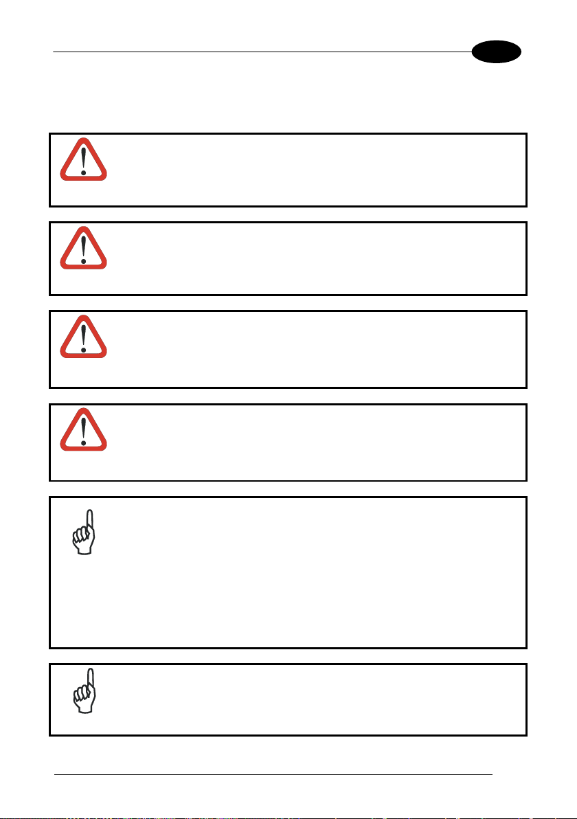
The Single Dock can be connected to the Host using the A to B USB cord included in
the box.
Once the host has been turned on, insert the Falcon X3+ into the dock.
Key:
A Host computer A) 94A150057 Falcon X3+ Single Slot
Dock
B) A to B USB straight cable
D 94ACC1381 Power Adapter
(included in the box)
Connection through the cradle complies to USB 2.0 standard.
NOTE
The actual data transfer speed can be appreciably lower than the
maximum theoretical speed.
NOTE
Page 30
1 FALCON™ X3+
22
3
A B C D A B C
D
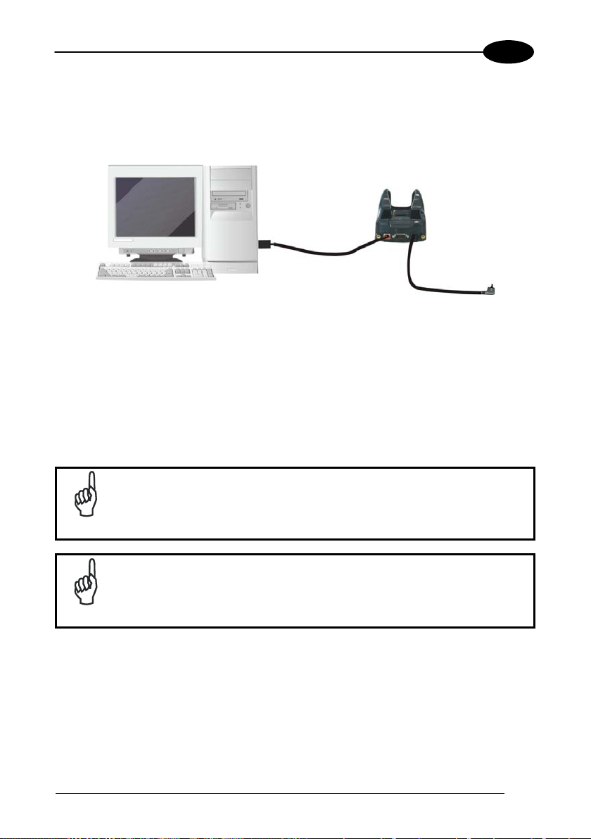
3.2 CONNECTION TO USB PERIPHERALS
To connect the Falcon X3+ to a U SB keyboard or a memory device, connect the
terminal to the Datalogic 94A051969 cable or to the Datalogic 94A051971 cable
(together with a standard A to micro A USB cable).
For all these devices maximum current withdrawal must be below 100mA.
Key:
A Keyboard with USB interface C 94A051969 Micro USB Host Cable/
94A051971 Handylink Micro USB Host
Cable
B Falcon X3+ D Standard A to Micro A USB Cable
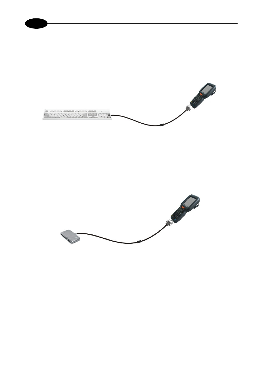
Key:
A USB hard drive/ external
memory source
C 94A051971 Handylink Micro USB Host
Cable
B Falcon X3+ D Standard A to Micro A USB Cable
Page 31

CONNECTIONS
23
3
B D C A E
Connect the Single Slot Dock to the peripheral using the A to B USB cord included in
the box (together with a standard USB cable if needed).
A USB Peripheral (memory) D 94A150057 Falcon X3+ Single Slot Dock
B Standard A to Micro A USB
E 94ACC1381 Power Adapter
Cable
C A to B USB straight cable
(included in the box)
Falcon X3+ works with most of the mentioned USB peripherals. In
any case, we can’t guarantee the interoperability of Falcon X3+ with
NOTE
all devices on the market.
Connection complies to USB 2.0 standard.
NOTE
The actual data transfer speed can be appreciably lower than the
maximum theoretical speed.
NOTE
Page 32

1 FALCON™ X3+
24
3
A B C A B C D
3.3 RS232 CONNECTION
You can use the Datalogic 94A051972 cable to directly connect the Falcon X3+ to a
host computer to transfer data through the RS232 interface.
Key:
A Host computer C Falcon X3+
B 94A051972 Handylink Micro RS232
Client Cable
The Single Slot Dock can be connected to the Host by means of a standard null
modem cable such as Datalogic 94A051020 CAB-427 for 9-pin connections.
Once the Host has been turned on, insert the Falcon X3+ into the dock.
Key:
A Host Computer C 94A150057 Falcon X3+ Single
Slot Dock
B 94A051020 CAB-427 RS232
D 94ACC1381 Power Adapter
Null Modem Cable
Page 33

CONNECTIONS
25
3
A B C
A
3.4 WLAN CONNECTION
Falcon X3+ 802.11 a/b/g/n radio models can communicate with the host using the
on-board radio frequency component and an Access Point connected to the host
computer.
For models using the 802.11 a/b/g/n radio, you can find information about the applet
for radio configuration: http://www.summitdatacom.com/SCU.htm
To launch this utility you can tap the specific icon if it is visible on the taskbar or you
can select the menu item: Start-> Summit and tap the ‘Summit Client Utility’ icon.
.
Key:
A) Falcon X3+
B) Access point
C) Host – Application Server
Page 34

26
3
Area coverage and radio performance may vary, due to
NOTE
NOTE
NOTE
NOTE
1 FALCON™ X3+
802.11 a/b/g/n radio module is on by default, in order to avoid
wasting energy, you can switch it off using the Wireless
Communications applet.
Suspending the terminal powers off the 802.11 a/b/g/n radio and
drops the radio connection. When the terminal resumes, depending
on the radio power mode and security protocol selected, it may take
up to 30 seconds for the 802.11 a/b/g/n radio driver to re-associate
the radio to the network.
environmental conditions, access point types or interference caused
by other devices (microwave ovens, radio transmitters, etc.).
In case of heavy usage the Falcon X3+ may get warm; t his is n or mal
and does not mean a malfunction.
Page 35

CONNECTIONS
27
3
B
A
3.5 WPAN CONNECTIONS
Falcon X3+ models with Bluetooth can communicate with other Bluetooth
devices, such as a printer, within a range of 10 m, using the on-board Bluetooth
module.
Key:
A) Falcon X3+
B) Bluetooth printer
NOTE
NOTE
NOTE
In order to extend battery life, the Bluetooth module is off by
default. If you need to have Bluetooth
working, the module must be
powered on using the Wireless Manager applet (see par. 4.6.6), and
perform the Discovery procedure (see par. 4.7.2).
Suspending the terminal powers off the Bluetooth radio and drops
the piconet (Bluetooth
takes approximately 10 seconds for the Bluetooth
connection). When the terminal resumes, it
radio driver to re-
initialize the radio.
Area coverage and Bluetooth radio performance may vary, due to
environmental conditions or interference caused by other devices
(microwave ovens, radio transmitters, etc.).
Page 36

1 FALCON™ X3+
28
3
Unauthorized antennas, modifications or attachments could
3.6 WIRELESS AND RADIO FREQUENCIES WARNINGS
Use only the supplied or an approved replacement antenna.
damage the product and may violate laws and regulations.
WARNING
Most modern electronic equipment is shielded from RF signals.
However, certain electronic equipment may not be shielded against
the RF signals generated by Falcon X3+.
WARNING
Datalogic recommends persons with pacemakers or other medical
devices to follow the same recommendations provided by Health
Industry Manufacturers Associations for mobile phones.
WARNING
Persons with pacemakers:
• Should ALWAYS keep this device more than twenty five (25) cm
from their pacemaker and/or any other medical device;
• Should not carry this device in a breast pocket;
• Should keep the device at the opposite side of the pacemaker
and/or any other medical device;
• Should turn this device OFF or move it immediately AWAY if
there is any reason to suspect that interference is taking place.
• Should ALWAYS read pacemaker or any other medical device
guides or should consult the manufacturer of the medical device
to determine if it is adequately shielded from external RF energy.
In case of doubt concerning the use of wireless devices with an
implanted medical device, contact your doctor.
Turn this device OFF in health care facilities when any regulations
posted in these areas instruct you to do so. Hospitals or health care
facilities may use equipment that could be sensitive to external RF
energy.
WARNING
Page 37

CONNECTIONS
29
3
WARNING
WARNING
WARNING
RF signals may affect improperly installed or inadequately shielded
electronic systems in motor vehicles. Check with the manufacturer
or its representative regarding your vehicle. You should also
consult the manufacturer of any equipment that has been added to
your vehicle.
An air bag inflates with great force. DO NOT place objects,
including either installed or portable wireless equipment, in the area
over the air bag or in the air bag deployment area. If a vehicle’s
wireless equipment is improperly installed and the air bag inflates,
serious injury could result.
Turn off the device when in any area with a potentially explosive
atmosphere. Observe restrictions and follow closely any laws,
regulations, warnings and best practices on the use of radio
equipment near fuel storage areas or fuel distribution areas,
chemical plants or where any operation involves use of explosive
materials.
Do not store or carry flammable liquids, explosive gases or
materials with the device or its parts or accessories.
Areas with a potentially explosive atmosphere are often, but not
always, clearly marked or shown.
Sparks in such areas could cause an explosion or fire, resulting in
injury or even death.
Page 38

1 FALCON™ X3+
30
3
Today Screen
Start Menu
4 USE AND FUNCTIONING
The use of the Falcon X3+ depends on t he application software loaded. However
there are several parameters that can be set and utilities that can be used to perform
some basic functions such as data capture, communications, file management, etc.
4.1 STARTUP
The Falcon X3+ turns on when the battery pack or the external supply is inserted and
the ON/OFF Power button is pressed.
After the battery pack is installed, use the [ON/OFF] key to turn the mobile computer
on and off.
As soon as the mobile computer is on, the Windows Embedded Handheld 6.5
desktop configuration will appear on the screen. Wait a few seconds before starting
any activity so that the mobile computer completes its startup procedure.
Use the stylus (par. 4.1.1) as suggested to select icons and options.
The mobile computer goes into power-off (low power with display and k eyboard
backlight off), when it is not used for more than a programmable timeout, which is
Page 39

USE AND FUNCTIONING
31
4
Touch the screen once with the stylus to open items and select
Hold the stylus on the screen and drag across the screen to
Tap and h old the stylus on an i tem to see a list of actions
up menu that appears, tap the
defined in the POWER applet of the Control Panel. In this mode it can be awakened
(resuming operation) by the [ON/OFF] key.
The mobile computer can also be awakened or suspended
programmatically.
NOTE
4.1.1 Using the Stylus
The stylus selects items and enters information. The stylus functions like a mouse.
Tap:
Drag:
Tap-and-hold:
options.
select text and images. Drag in a list to select multiple items.
available for that item. On the popaction you want to perform.
To recalibrate the touch screen use the Screen Applet (see par. 4.6.7).
Use only original Datalogic styluses supplied with the product itself.
In harsh applications, use of screen protectors should be taken into
CAUTION
consideration, in order to extend the touch screen operating life.
To prevent damage to the screen, do not use sharp objects or any
tool other than the Datalogic provid ed sty lus .
Do not apply too much pressure when touching the screen.
For applications where an intensive use of the touch screen is
foreseen, please consider that touch screen components are subject
to progressive wear.
Page 40

1 FALCON™ X3+
32
4
4.2 WINDOWS EMBEDDED HANDHELD WELCOME W IZARD
In Windows Embedded Handheld, at the very first Falcon X3+ startup, following a
clean boot or following a R egistry restore to default values, the mobile computer
startup (see par. 4.1) is preceded by the Welcome Wizard.
Welcome Wizard Screen
The Welcome Wizard allows the user to calibrate the touch screen (see par. 4.6.7)
Touch Screen Calibration Screen
Page 41

USE AND FUNCTIONING
33
4
4.3 DATA CAPTURE
To capture data first of all tap Start > Settings > System > Decoding:
To configure and enable data capture parameters refer to par. 4.6.1.
Page 42

1 FALCON™ X3+
34
4
4.3.1 Laser Data Capture
To scan barcodes, point the Falcon X3+ laser model onto the code from a distance
within the reading range while pressing the SCAN key or the pistol trigger.
The lighted band emitted by the laser must completely cross the barcode as shown in
the figure below.
The XLR engine includes a pointer mode that projects a highly visible scan line at
longer ranges to make it easier to accurately target bar codes. The user simply holds
the trigger down until the aimer is on the appropriate code. Releasing the trigger then
initiates the bar code scan.
If the scan has taken place correctly:
− the Good Read LED glows steadily Green for a configurable time;
− if enabled, the Good Read Beep plays;
− if enabled, the GreenSpot projects a green spot onto the bar code image.
Page 43

USE AND FUNCTIONING
35
4
Remove the protective film cover over the Laser Output Window
before use.
NOTE
Page 44

1 FALCON™ X3+
36
4
4.3.2 Imager Data Capture
The Falcon X3+ Imager captures a picture of the entire bar code. The omnidirectional scanning does not require that the operator orient the bar code to align
with the scan pattern.
To read a 1D or 2D code, simply point the Falcon X3+ Imager model onto the code
and press the SCAN Key or the pistol trigger.
The Falcon X3+ Imager uses an intelligent aiming system pattern, similar to those on
cameras, indicating the field of view, which should be positioned over the code:
Aiming System
If the aiming system pattern is centered over the entire symbology as shown in the
following figure, either wait for the timeout or release the Scan key to capture the
image.
A red beam illuminates the code, which is captured and decoded. You will get a good
read.
Page 45

USE AND FUNCTIONING
37
4
Linear barcode
2D Matrix symbol
ÌBX3ÉÎ
Relative Size and Location of Aiming System Pattern
The field of view changes its size as you move the reader closer or farther away from
the code. The field of view indicated by the aiming system pattern will be smaller
when the Falcon X3+ Imager is closer to the code and larger when it is farther from
the code.
Symbologies with smaller bars or elements (mil size) should be read closer to the
unit. Symbologies with larger bars or elements (mil size) should be read farther from
the unit (see par. 5.1 for further details).
If the scan has taken place correctly:
− the Good Read LED glows steadily Green for a configurable time;
− if enabled, the GoodReadSound emits an acoustic signal;
− If enabled, the Good Read Beep plays.
Page 46

38
4
4.4 DESCRIPTION OF THE KEYS
The Falcon X3+ comes with three different keyboards:
- a 52-key alphanumeric keyboard
- a 29-key numeric keyboard.
4.4.1 52-Key Alphanumeric Keyboard
1 FALCON™ X3+
Page 47

USE AND FUNCTIONING
39
4
4.4.2 52-Key Terminal Emulation 5250 Keyboard
Page 48

40
4
Main Keys Function
Direct access to F1-F4.
you to
move forwards, backwards, upwards or downwards within
text fields, scroll through a Menu list or browse among
folder files.
Yellow modifier (toggle key): when pressed before a
Blue modifier (one shot key): when pressed before a
standard key, it enables the character or function printed in
KEY FUNCTION
1 FALCON™ X3+
Pressing the SCAN key starts barcode data capture.
If pressed after the Yellow toggle, these keys let
standard key, it enables the character or function printed in
yellow above the key.
blue above the key.
It powers the Falcon X3+ on or off. it is placed on the upper
left side of the terminal.
Page 49

USE AND FUNCTIONING
41
4
4.4.3 Numeric Keyboard
Page 50

42
4
Main Keys Function
let you move forwards, backwards,
upwards or downwards within text fields, scroll through a
Yellow modifier (toggle key): when pressed before a
standard key, it enables the character or function printed
Blue modifier (one shot key): when pressed before a
in blue above the key.
KEY FUNCTION
1 FALCON™ X3+
Pressing the SCAN key starts barcode data capture.
Pressing cursor keys
Menu list or browse among folder files.
in yellow above the key.
standard key, it enables the character or function printed
It powers the Falcon X3+ ON or OFF. It is placed on the
upper left side of the terminal.
Page 51

USE AND FUNCTIONING
43
4
4.4.4 Resetting the Falcon X3+
There are several reset methods for the Falcon X3+.
A warm boot terminates an unresponsive application and clears the working RAM,
but preserves the file system. Registry is restored from persistent memory if available
or returned to factory default.
A cold boot forces all applications to close, completely reinitializing the system. It
clears the working RAM, but the file system is preserved. Registry is restored from
persistent memory.
A clean boot restores the Falcon X3+ to a clean configuration: both the Registry and
the file system returns to a clean status that conforms to factory default.
Warm Boot
To perform a warm boot, press and hold the following keys simultaneously:
+ +
Cold Boot
To perform a cold boot, do the following steps:
1. Turn off the Falcon X3+ by pressing the on-off key.
2. Pull the battery latch down and remove the battery pack.
3. Press and hold the scan button and then press the reset button.
4. Insert the battery pack.
5. Turn on the Falcon X3+ by pressing the on-off key.
Page 52

1 FALCON™ X3+
44
4
Warm Boot
Cold Boot
Clean Boot
Registry
Restored from
flash
Restored from
flash
Clean configuration (no user
config)
File
System
Preserved
Preserved
Clean Installation (no user files)
Clean Boot
To perform a clean boot, do the following steps:
1. Perform a Cold Boot (see Cold Boot)
2. Press and hold down the 0 and Esc keys simultaneously and then press the onoff key:
+
A dialog box will appear asking for confirmation. Press the Enter Key.
Page 53

USE AND FUNCTIONING
45
4
Time-out (imager models).
(left side)
(center)
4.5 STATUS INDICATORS
4.5.1 LED Status
The Falcon X3+ provides three different LEDs signaling the mobile computer status.
LED STATUS
Scanning LED is ON from the time the
Good Read
(right side)
Red
user hits the scan button or the trigger
button until the bar code is decoded
(laser models)
Green
Charging Status
Red It is solid while charging.
Keyboard Status
Yellow solid Yellow alternate key mode.
Blue solid Blue alternate key mode
Pink CapsLock enabled.
Green
Red blinking It blinks in case of charge fault.
Off Keyboard in primary.
Scanning LED is ON, showing a good
decode.
It is solid once the charging process has
been completed (full charge).
Page 54

1 FALCON™ X3+
46
4
Opens the Connections balloon, which includes hypertext links
Opens the Volume balloon, which allows the user to control the
call volume, to mute all volumes, and to control
4.5.2 Taskbar
The title bar provides information about the time, the battery level, the keyboard
function, and the decoding status.
Windows Embedded Handheld Taskbar
ICONS DESCRIPTION
Zooms the screen.
to the Wireless Manager and the Connections applet. (see
par.
4.6.6).
Displays the system battery status.
main volume, inthe vibrator.
Opens Clock & Alarms control panel applet. It allows the user to
set date, time and alarms.
Page 55

USE AND FUNCTIONING
47
4
4.6 SETTINGS
From the Start menu, tap Settings. The settings are organized hierarchically.
Control panel applets are displayed as icons; each icon corresponds to one applet:
Windows Embedded Handheld Control Panel
Page 56

1 FALCON™ X3+
48
4
4.6.1 Data Capture Configuration
You can configure the Falcon X3+’s decoding options by tapping Start -> Settings ->
System -> Decoding:
There are two sections in the Decoding control panel, each containing additional
pages. There are seven General Configuration pages and multiple Barcode
symbology pages.
Decoding configuration pages
Select the desired configuration from the options shown in the figure below, and the
other Decoding Properties figures on the following pages.
Select General, 1D Bar Code or 2D Bar Code, then use the menu or tap the left and
right arrow keys to navigate the different pages of the Decoding utility. The menu
options will change to reflect the items most recently selected.
Page 57

USE AND FUNCTIONING
49
4
Notification
From the Decoding menu, tap Configure > General > Notification. Use it to set
volume, tone, duration, and number of various types of beeps.
Good Read
From the Decoding Properties applet, tap Configure > General > Good Read. Use it
to enable Good Read indications, the LED, the use of Green Spot and a to set the
decoding timeout for decoding labels.
Page 58

1 FALCON™ X3+
50
4
Formatting
From the Decoding Properties page, tap Configure > General > Formatting. Use it to
configure prefix, suffix and data separator character strings.
General Options
From the Decoding menu, tap Configure > General > General Options. Select from
Label Programming Enable, Symbology IDs and Group Separator Replacement.
Page 59

USE AND FUNCTIONING
51
4
Decoding Options
From the Decoding Properties applet, tap Configure > General > Decoding Options.
Use it to configure the User ID for symbologies, Redundancy and Aggressive
Decoding (if supported by the decoding module). Select a symbology to view or
change the available properties settings.
Page 60

1 FALCON™ X3+
52
4
Spot Beam
From the Decoding Properties applet, tap Configure > General > Spot Beam. It
allows enabling and configuration of Spot Beam and triggering modes.
It is only available on d evices equipped with laser and advanced long range laser
decoding modules that support the Spot Beam Feature.
Page 61

USE AND FUNCTIONING
53
4
Imager Options
From the Decoding Properties applet, tap Configure > General > Imager Options. It
configures illumination, target beam and Pick List mode, and triggering modes.
It is only available on devices equipped with 2D decoding engines.
Page 62

1 FALCON™ X3+
54
4
Devices
From the Decoding Properties applet, tap Configure > General > Devices. Use it to
enable or disable the keyboard wedge for Barcode scanner.
Page 63

USE AND FUNCTIONING
55
4
1D Barcode Symbology Pages
Use the drop-down menus from Configure > 1D Barcode, or tap the left and right
arrow keys to navigate the different pages of the barcode symbology pages.
Each barcode symbology opens to its own page, as shown in the figure below. Refer
to the sample symbology control panels for examples of the types of fields and
options you can modify.
Codabar: Select Enable, Min/Max Lengths, Enable Checksum, Send Checksum,
Send Start/Stop, Convert to CLSI and Wide Gaps.
Page 64

1 FALCON™ X3+
56
4
Decoding Settings
Select from the Decoding Properties Settings menu to restore previous
configurations and/or other available default settings. Choose from:
• Factory Defaults
• Minimum Settings
• Maximum Settings
• Save (New Settings)
• Revert to Saved Settings
The settings are saved when you tap ‘Yes’.
When open, Decoding Properties acts as a simple barcode test tool that provides the
Data decoded and the Data Type of the barcode scanned.
Page 65

USE AND FUNCTIONING
57
4
4.6.2 Buttons
From the Start menu, tap Settings > Personal > Buttons.
On the Program Buttons tab, customize the program hardware buttons to launch your
most used applications. Under ‘Select a button’, tap the button you want to assign a
program to, and then select a program from ‘Assign a program’.
To configure the way the up/down control repeats, use the Up/Down Control applet
(Start > Settings > Personal > Buttons and then tap Up/Down Control).
Page 66

1 FALCON™ X3+
58
4
4.6.3 DL Buttons
In Windows Embedded Handheld devices, <F1>-<F10> buttons (excluding F5) are
assigned by Windows to default applications. F5 is commonly used by applications to
refresh the few, but is not explicitly controlled by default.
To disable an assigned function, tap Start > Settings > System > DL Buttons to
display the DL Buttons window:
Select the button you want to disable. Select the function ‘None’ and the tap OK.
Page 67

USE AND FUNCTIONING
59
4
To add the button, tap ‘New’ and then press the button you wish to add:
To assign a new function to the button, select the desired function and then tap ‘OK’:
To restore the old settings, do a clean boot
Page 68

1 FALCON™ X3+
60
4
4.6.4 Triggers
Triggers are special customizable buttons that are mapped by default by DL Buttons.
Also, they can be set as wakeup buttons:
TRIGGERS
DEFAULT CONFIGURATION
Assigned Function Wake-up
Scan Bar Code Disabled
Pistol Trigger
Bar Code Enabled
Page 69

USE AND FUNCTIONING
61
4
4.6.5 Application Switcher
The application switcher provides the same functionality as the standard Windows®
Alt+Tab function. This allows the user to switch between the various open
applications.
The application switcher can be activated via an assigned shortcut key specified in
the “DL Buttons” tab (refer to par. 4.6.3). When the assigned button is pressed, the
dialog shown below will be displayed:
The <Esc> key can be used to close the Application Switcher.
NOTE
Press the assigned button to open t he application switcher. Press the assigned
button to cycle through the running applications when the dialog is open. Press
<Enter> to switch to the selected application or <Esc> to close the application
switcher.
Page 70

1 FALCON™ X3+
62
4
4.6.6 Wireless Communications
The Wireless Manager application is a s ort of 'Control Panel' for wireless
connections. From here it's possible to turn on or off bluetooth® and radio modules.
Open the Wireless Manager by tapping Start > Settings > Connections > Wireless
Manager, or by tapping the connectivity icon on the taskbar and then tapping the
"Wireless Manager" hypertext link (see par. 4.5.2). The following window will appear:
Page 71

USE AND FUNCTIONING
63
4
Summit Client Utility (SCU)
Wireless networking has a customized control, Summit Client Utility (SCU). From the
Start menu, tap: Summit > SCU:
The SCU will open to the “Main” tab:
Summit Client Utility
Page 72

64
4
1. To create a new profile, tap the "Profile" tab:
1 FALCON™ X3+
Information about the wireless network can be entered directly in the profile tab or by
pressing “Scan” when the desired network SSID is in range.
2. At the "Scan" screen, select the desired SSID:
Page 73

USE AND FUNCTIONING
65
4
3. Tap the "Configure" button
4. Follow the on-screen instructions to configure security parameters for your
network. For more detailed settings specific to your installation please contact
your wireless network administrator.
5. When finished, tap “Commit” to save your settings.
6. Return to the “Main” tab, if you have not previously selected “Commit” you will be
prompted to save your changes.
Page 74

1 FALCON™ X3+
66
4
7. At the “Main” tab select the profile you just created. If you used the “scan” button
the desired profile will have the same name as the SSID.
8. Use the “Status” tab to check connectivity to the network.
More detailed information about the applet for radio configuration can be found at
http://www.summitdata.com/Documents/summit_users_guide_3_03.html
.
Page 75

USE AND FUNCTIONING
67
4
4.6.7 Stylus Calibration
You might need to recalibrate the touch screen (i.e. when you attempt to select one
item with the stylus, another item is erroneously selected).
To recalibrate the touch screen, complete the following steps:
1. Select Start > Settings > System > Screen to open the Screen
Settings.
2. Tap Align Screen to open the Calibration screen shown in the figure below:
3. Carefully press and briefly hold stylus on the center of the target. Repeat as the
target moves around the screen.
New calibration settings are persistently saved in Registry.
Page 76

1 FALCON™ X3+
68
4
Startup Stylus Calibration
When clean booting the terminal, a Welcome Wizard (with Stylus Calibration) comes
up if valid calibration settings are not available.
Page 77

USE AND FUNCTIONING
69
4
4.6.8 Audio Settings
There are two applets that control volume: Audio and Volume & Sounds.
Audio
From the Start Menu, tap Settings > System > Audio:
The audio control panel can be used to independently set the playback or recording
volume for different types of audio inputs and outputs, such as a headset, powered
mobile dock, or the internal speakers and microphone.
Audio Windows
Page 78

70
4
Sounds & Notifications
Sounds Tab
From the Start Menu, tap Settings > Sounds and Notifications:
1 FALCON™ X3+
The Sounds & Notifications applet configures audio features of all speakers and
headphones:
Page 79

USE AND FUNCTIONING
71
4
You can also set the volume of a paired Bluetooth®headset. Tap:
Start > Settings > System > Bluetooth Manager, select the Connections tab and then
select the headset pairing in the Paired Devices list. The following window will
appear:
Page 80

1 FALCON™ X3+
72
4
4.7 CONNECTING TO OTHER COMPUTERS
To connect the Falcon X3+ to another device (i.e. Host PC) which run Windows,
several programs are available. These programs require specific electrical
connections in order to function properly.
4.7.1 Windows Mobile® Device Center
The desktop application Windows Mobile® Device Center gives you the ability to
synchronize information between a desktop computer and your Falcon X3+.
Synchronization compares the data on the Falcon X3+ with that on the desktop
computer and updates both with the most recent information.
Windows Mobile® Device Center can be downloaded from Microsoft website
www.microsoft.com
run Windows XP or earlier, you have to download Microsoft ActiveSync.
You can establish a connection to your Falcon X3+ through the following interfaces:
− USB either directly or through the Single Dock
− RS232 either directly or through the Single Dock
− Bluetooth® (see par. 4.7.2)
To establish a par tnership between the Falcon X3+and a hos t PC, start Windows
Mobile® Device Center and follow the steps below:
1. Connect the Falcon X3+ to the host PC. Windows Mobile® Device Center
configures itself and then opens.
2. On the license agreement screen, click Accept.
3. On the Windows Mobile® Device Center’s Home screen, click Set up your
device.
4. Select the information types that you want to synchronize, then click Next.
5. Enter a device name and click Set Up.
When you finish the setup wizard, Windows Mobile® Device Center synchronizes the
mobile computer automatically. Microsoft® Office Outlook® emails and other
information will appear on your device after synchronization.
. It is only compatible with Windows Vista and Windows 7; if you
Page 81

USE AND FUNCTIONING
73
4
NOTE
4.7.2 Bluetooth® Manager Device Setup
Using the Falcon X3+ to connect to another device
To create a Bluetooth® pairing between your device and another device that has
Bluetooth® capabilities, ensure that the two devices are turned on, discoverable, and
within close range.
1. Open the Bluetooth® control panel by tapping Start > Settings > System >
Bluetooth Manager:
2. Search for available Bluetooth® devices by tapping the button for the type of
device you want (Printer, Serial or All) or tap the Discovery tab and then tap the
Discover button to skip this step. The Falcon X3+ will search for Bluetooth®
devices within range.
If you attempt to set up a connection when the Bluetooth® radio is
disabled, you will receive a message reminding you that the radio is
turned off, and asking if you want to turn it on. Tap Yes if you need to
enable the Bluetooth® radio.
Page 82

1 FALCON™ X3+
74
4
3. Once searching is complete, Bluetooth® devices will be displayed in the
Discovery tab. You can set up a connection to a device in the list by selecting
the device and then tapping the 'Connect' button:
To create a pairing:
1. Select a service:
2. Configure any encryption, authentication, or virtual port options required by the
service selected.
Page 83

USE AND FUNCTIONING
75
4
Icon Service
Dialup Networking
Printer
Object Push (OPP) or Object Exchange (OBEX)
ActiveSync
Human Interface Device (HID) - Keyboard
Serial
Personal Area Network (PAN)
Modem
Headset
Handsfree
Virtual Port allows you to specify the incoming port, which is used to communicate
serially with an incoming device just as if it were a physical COM port. This option is
available only if you have selected a Printer or Serial service.
Page 84

1 FALCON™ X3+
76
4
You can also select Encrypt or Authenticate from the Bluetooth® control panel to
apply or modify those settings.
1. To require Authentication, check the checkbox, then tap OK.
2. If required, the Authentication Request dialog will then open, requesting that you
enter a PIN. Use the Input Panel or the keyboard to type the PIN.
3. Tap OK to complete.
Page 85

USE AND FUNCTIONING
77
4
The dialog will also appear when an Authentication request is received from another
device.
Once you have set up a P airing, you can view the settings by double-tapping its
name in the Connections tab. Tap the arrow to change the Virtual Port, or Delete to
remove the device pairing. Tap Sync to initiate a Sync (available only if the service is
an ActiveSync connection).
Page 86

1 FALCON™ X3+
78
4
Using your device to connect to the Falcon X3+
Before turning on Bluetooth® ensure that the two devices are within close range and
that both Bluetooth-enabled devices are discoverable.
1. Tap Start > Settings > System > Bluetooth Manager to open t he Bluetooth®
control panel.
2. Tap Settings. The Settings tab allows you to enable or disable the Bluetooth®
radio and specify settings for Incoming Connections.
Page 87

USE AND FUNCTIONING
79
4
3. Select or clear the “Enable Bluetooth Radio” check box. If you’re going to be
attaching a serial device (i.e. a scanner) to the Falcon X3+, use the Port control
to select a virtual COM port to use for the connection.
4. Tap ‘Find Me’ if you want to make the Falcon X3+ visible to other Bluetooth®
devices for 60 seconds, allowing them to set up a connection.
Page 88

1 FALCON™ X3+
80
4
NOTE
By default, Bluetooth® is turned off. If you turn it on, and then turn off
your device, Bluetooth® also turns off. When you turn on your device
again, Bluetooth® turns on automatically.
Page 89

USE AND FUNCTIONING
81
4
4.8 DATALOGIC FIRMWARE UTILITY
The Datalogic devices are equipped with a f ield upgradeable firmware mechanism.
Firmware updates are available on the Datalogic website:
http://www.datalogic.com/eng/support-services/automatic-datacapture/downloads/software-utilities-sw-2.html.
After you have downloaded the desired update, there are several ways you can
update the firmware on your device.
− Use Wavelink Avalanche™ if you have multiple Datalogic devices to update.
For more information refer to the dedicated section of the Wavelink website:
http://www.wavelink.com/Datalogic-device-downloads
− If Wavelink Avalanche™ is not available or you have only a f ew Datalogic
devices to update, use the Datalogic Firmware Utility (DFU), described below,
to install or update the firmware using an ActiveSync connection.
The following sections provide procedures for the retrieval and installation of the
most current firmware image onto a Datalogic device.
.
4.8.1 Retrieving a Firmware Image Update
The following instructions use Internet Explorer to retrieve the most current firmware
image.
1. Launch Internet Explorer on your PC and navigate to the Datalogic website.
2. Navigate to the Downloads section of the website.
3. Using the device selection fields,
click Save to begin copying the files to your local machine (or local network
location).
select the file you want to download, then
Page 90

1 FALCON™ X3+
82
4
NOTE
4.8.2 Installing DFU on the Host PC
The Datalogic Firmware Utility (DFU) provides administrators with a f ield upgrade
mechanism. You must have Microsoft® ActiveSync (for Windows XP devices) or
Windows Mobile® Device Center (for Windows 7 and Vista devices) already loaded
and running on t he host PC to use DFU. Refer to par. 4.7.1 for more information
about Windows Mobile® Device Center.
Prior to installing, you must remove any previous versions of DFU
installed on the host PC.
To install the Datalogic Firmware Utility, complete the following steps on the PC:
1. Go to the Datalogic website and download the most current version of the
Datalogic Firmware Utility. Unzip the file, then double-click to run DFU_Setup.
exe.
2. Click OK to continue once you have removed previous versions of DFU.
3. The Welcome to DFU Setup Program screen opens.
− Please exit all Windows applications before running this installer.
− Click Next to continue the Setup.
4. Follow the onscreen instructions to complete the installation.
Page 91

USE AND FUNCTIONING
83
4
NOTE
4.8.3 Updating the Firmware
After copying the firmware image to the host PC (see par. 4.10.1) and installing DFU
(see par. 4.8.2), you can upgrade the firmware on your Datalogic device.
The following steps require that you have already established an
ActiveSync or W indows Mobile® Device Center connection between
the host computer and the Datalogic device.
1. Go to Start > Programs > Datalogic > DFU > Datalogic Firmware Utility.
2. Verify that ActiveSync is selected by clicking Communications > WMDC/
ActiveSync.
3. Click browse (...) and navigate to the location where you saved the firmware
file for your terminal.
4. Select the current *.out file and click Open.
5. Click Update.
6. DFU will compare the selected firmware image with the firmware already
loaded on the device; if the image is compatible with the connected device,
DFU will proceed to update the firmware image on your device.
7. After the firmware of your device has been updated, DFU will automatically
perform a warm reset of the device.
Page 92

1 FALCON™ X3+
84
4
4.9 DATALOGIC CONFIGURATION UTILITY
Datalogic Configuration Utility (DCU) is a Datalogic Windows-based utility tool
allowing the uploading, modifying and downloading of the configuration of a Datalogic
device. Configuration settings include Scanner, Control Panel, and Datalogic
Desktop Utility (DDU). The DCU installer is downloadable from the Datalogic website
http://www.datalogic.com/eng/support-services/automatic-data-
(
capture/downloads/software-utilities-sw-2.html).
DCU functions in both direct (with an A ctiveSync connection) and indirect (with
Wavelink Avalanche™) modes.
In direct mode, connect a device through ActiveSync and then click on the Get from
Device icon to receive the device’s current configuration.
Once loaded, the Configuration Tree (on the left side of the window) is used to
navigate the device’s configuration. The right side of the window is a w ork area
where the values of different parameters may be s et for each branch of the
configuration tree. Click on the parameter group branch to open it and inspect the
parameters you wish to modify.
After altering the device’s configuration, the new configuration can be sent to the
terminal by clicking on the Send to Device icon.
Reference the Wavelink Avalanche™ documentation on the Wavelink website
(www.wavelink.com/Datalogic-device-downloads
for DCU, which will allow you to update the configuration of multiple devices
simultaneously over Wi-Fi.
) for a description of indirect mode
Page 93

USE AND FUNCTIONING
85
4
NOTE
4.10 DATALOGIC DESKTOP UTILITY
Datalogic Desktop Utility (DDU) allows administrators to configure Windows
Embedded Handheld devices to control individual user access. This includes the
ability to:
®
CE and
• Prevent users from changing your device OS settings.
• Use the Application Selector to replace the desktop with a s election of
authorized applications.
• Restrict user access in Internet Explorer.
• Set up configuration and customized error recovery mechanisms.
• Create quick access hot keys and configure trigger actions.
To open DDU for the first time, tap Start > Settings > System > and then tap the icon
for “Datalogic Desktop Utility”.
You can also open DDU by pressing the appropriate key shortcut. The default is “Alt
+ 6”.
The key combination can be changed by using DL Buttons to
redefine the association for specific keys (such as <F1>-<F10>). See
par.4.6.3. for more information.
Page 94

86
4
4.10.1 Administrative Options (Admin tab)
such as Windows Access Restrictions and Application
Selector.
password in the text box. This allows the user to
specify a pas sword when this utility is launched. By
default the password is “1234”. A password can consist
To change or remove the password, enter a new value,
re-enter the new value, and select/tap “Set Password”.
all the functions on al l the tabs. After you select this
When you open the DDU control panel, the “Admin” tab appears.
1 FALCON™ X3+
COMMAND DESCRIPTION
Enable Datalogic Desktop Select/tap this checkbox to activate the DDU functions
Enter Password Enter a
of all standard keyboard characters.
Re-Enter Password Carefully re-enter the password in the second text box.
Set Password Select/tap “Set Password” to enable the password.
Set Defaults Select/tap “Set Defaults” to reset the default values of
option, you will receive a prompt to verify this selection.
Page 95

USE AND FUNCTIONING
87
4
Setting a Password
To set a password:
1. Enter a password in the field. This allows the user to specify a password when
this utility is launched. By default the password is “1234”.
Be sure to record the Password for future reference.
NOTE
2. Re-enter the password in the second field.
3. Select/tap “Set Password” to enable the password.
4. Select/tap “OK” to close the “Set Password Confirmation” dialog.
You must select/tap “Set Password” prior to exiting DDU in order to
store and activate your new password. It is not necessary to select
NOTE
“Enable Datalogic Desktop”.
If you select/tap “Set Defaults” it will remove all custom settings and
restore all the factory default settings, except a previously set
password.
CAUTION
Changing a Password
To change to a new password:
1. Enter a new value in the “Enter Password field”.
2. Re-enter the new value in the “Re-enter Password” field.
3. Select/tap “Set Password”.
Page 96

1 FALCON™ X3+
88
4
Removing a Password
To remove a password:
1. Enter blanks in both “Password” fields.
2. Select/tap “Set Password”.
Password Request Dialog Box
Once the password is set, the next time you open the “Datalogic Desktop Utility”, the
DDU Password dialog box opens.
This dialog box will only open if a password was defined.
1. Type in your password using either the keypad on the unit, or using the stylus on
the soft input panel (SIP).
If you enter an incorrect password, the system will prompt you to input the
correct one.
2. Select/tap “OK” to verify the password. Or tap “X” to cancel.
Page 97

USE AND FUNCTIONING
89
4
4.10.2 Locked Web Browser Options (LockedWeb tab)
Tap the LockedWeb tab to access the Locked Web Browser Configuration.
Locked Web Browser is disabled by default. To enable, go to
“Advanced settings” on the next page for more information.
NOTE
For additional information about Locked Web Browser commands and metatags, see
section 4.12, “Locked Web Browser”.
Error Page Redirection
Use the Error Redirection option to provide customized recovery from common
errors. When an error occurs, the browser can redirect access to a specified error
page with instructions on how to recover from the problem.
Locked Web Configuration Tab
Page 98

1 FALCON™ X3+
90
4
(400) Invalid Syntax, (403) Request Forbidden, (404) Object Not
Internal Server Error, (501) Server Can't Do That, Generic Error,
Network Disconnected
Edit this textbox to associate a website or html file with the specified
error.
available for Windows Mobile.
icons can be configured on the Status tab of DDU.
ll be trapped by the Locked Web Browser to
prevent the user from accessing unsafe parts of the system. For
safe key presses (e.g. Alpha numeric) will still get processed by the
rmal. For example entering a number in
all Locked Web Browser command keys will work (e.g. Ctrl+0 to
all Locked Web Browser command keys will work (e.g. Ctrl+0 to
exit).
Error Redirection options
Error Type The “Error Type” pull-down list displays available Error Types:
Found, (406) No Response Format, (410) Page Doesn't Exist, (500)
Error Page
Other options
Full Screen Set the web browser in full screen mode. This is the only option
Status Icon Enable or disable the status icons view (see par. 4.10.3). The status
Trap Keys When checked:
− all key presses wi
example, pressing Ctrl+O to Open a File will not work;
−
Locked Web Browser as no
a text field on a web page;
− DL Buttons keys will not work in the LockedWeb Browser;
−
exit).
− When unchecked:
− all keys will be processed normally by the system and the browser;
− DL Buttons keys will work normally;
−
Exit
Password
When checked, a password will be required before the Locked Web
Browser can exit. This password is different than the DDU exit
password, with a default value of “0000”, and can be changed in the
Browser
Home Page
Advanced Pressing this button will launch a dialog used to enable Locked Web
“Advanced” settings.
This sets the Internet Explorer home page, regardless of the enable
state of the Locked Web Browser.
Browser and to configure Advanced settings.
Page 99

USE AND FUNCTIONING
91
4
General Tab
Context Menu
Advanced settings
Page 100

92
4
Enable Locked
Web Browser
r when Internet
Explorer is launched.
Prevents the browser from loading the local intranet page from
cache instead of navigating to the “Network Disconnected” error
redirection page.
cts browsing only to files and
Click the “Add” button to add allowed URLs to the white list. Other
n is enabled. Domain names
Pressing this button brings up a di alog which allows the user to
change the password required to exit the Locked Web Browser
Advanced Locked Web Browser options
General
When checked, enables the Locked Web Browse
Disable Cache
1 FALCON™ X3+
Allowed Website
List
Enables a “ white list,” which restri
URLs in the Allowed Website list (accessed by the “…” button).
The following dialog appears:
Allowed Website List
sites will be restricted when the optio
must be exactly specified.
Change Exit
Password
(when the “Exit password” option is selected on the LockedWeb
tab in DDU).
 Loading...