

Page 1

STARModem™
QUICK REFERENCE
GUIDA RAPIDA
GUIDE RAPIDE
KURZANLEITUNG
GUÍA RÁPIDA
Page 2

DATALOGIC S.p.A.
Via Candini, 2
40012 - Lippo di Calderara di Reno
Bologna - Italy
STARModem™
Ed.:06/2003
ALL RIGTHS RESERVED
Datalogic reserves the right to make modifications and improvements without prior notification.
Datalogic shall not be liable for technical or editorial errors or omissions contained herein, nor for incidental or
consequential damages resulting from the use of this material.
Product names mentioned herein are for identification purposes only and may be trademarks and or
registered trademarks of their respective companies.
© Datalogic S.p.A. 2002 - 2003
Preliminary
Page 3

CONTENTS
Using STARModem™..............................................................................................2
Installation...................................................................................................................3
System Connections................................................................................................... 3
RS232 Interface Connection......................................................................... 4
Pen Emulation Interface Connection............................................................. 4
Wedge Interface Connection.........................................................................5
STARModem™ Initial Setup....................................................................................5
STARModem™ Setup for Stand Alone Mode.............................................................7
STARModem™ Setup for STAR-System™ Mode .................................................10
STARModem™ Default Configuration...................................................................12
Warranty ...................................................................................................................12
Technical Features....................................................................................................13
Compliance............................................................................................................... 14
Antenna.....................................................................................................................68
Mounting Brackets ....................................................................................................68
Overall Dimensions................................................................................................... 69
STARModem™ Cable Pinout ................................................................................ 70
Typical Layout Applications.......................................................................................71
INDICE
STARModem™ - Descrizione e Uso......................................................................16
Installazione..............................................................................................................17
Sistema Radio - Collegamento .................................................................................17
Connessione con Interfaccia RS232........................................................... 18
Connessione con Interfaccia Pen ...............................................................18
Connessione con Interfaccia Wedge ..........................................................18
Configurazione Preliminare di STARModem™......................................................19
Configurazione di STARModem™ in Modalità Stand-Alone..................................21
Configurazione di STARModem™ in Modalità STAR-System™............................24
STARModem™ - Configurazione di Default ..........................................................25
Garanzia ...................................................................................................................25
Caratteristiche Tecniche ...........................................................................................26
Conformità ................................................................................................................27
Antenna.....................................................................................................................68
Mounting Brackets ....................................................................................................68
Overall Dimensions................................................................................................... 69
STARModem™ Cable Pinout ................................................................................ 70
Typical Layout Applications.......................................................................................71
iii
Page 4

SOMMAIRE
Utilisation de STARModem™ ................................................................................ 29
Installation................................................................................................................. 30
Connexion Systeme.................................................................................................. 30
Connexion RS232....................................................................................... 31
Connexion Emulation Crayon ..................................................................... 31
Connexion Interclavier ................................................................................ 32
Configuration Initiale de STARModem™ ...............................................................32
Configuration de STARModem™ en Mode Monoposte.........................................34
Configuration de STARModem™ en Mode STAR-System™ ................................37
STARModem™ - Configuration par Defaut............................................................39
Garantie ....................................................................................................................39
Caracteristiques Techniques..................................................................................... 40
Conformite ................................................................................................................41
Antenna.....................................................................................................................68
Mounting Brackets ....................................................................................................68
Overall Dimensions................................................................................................... 69
STARModem™ Cable Pinout ................................................................................ 70
Typical Layout Applications.......................................................................................71
INHALTSVERZEICHNIS
Beschreibung und Gebrauchsanweinsung................................................................43
Installation................................................................................................................. 44
Systemanschluß........................................................................................................44
RS232 - Schnittstelle...................................................................................45
Lesestiftschnittstelle.................................................................................... 45
Tastaturschnittstelle.................................................................................... 45
STARModem™ Anfangskonfiguration...................................................................46
STARModem™ Konfiguration für Stand-Alone-Mode........................................... 48
STARModem™ Konfiguration für STAR-System™ Mode ....................................51
STARModem™ Grundeinstellung.......................................................................... 52
Gewährleistung......................................................................................................... 52
Technische Daten..................................................................................................... 53
Konformität................................................................................................................53
Antenna.....................................................................................................................68
Mounting Brackets ....................................................................................................68
Overall Dimensions................................................................................................... 69
STARModem™ Cable Pinout ................................................................................ 70
Typical Layout Applications.......................................................................................71
iv
Page 5

INDICE
Utilización de los STARModem™..........................................................................55
Instalación................................................................................................................. 56
Conexión del Sistema...............................................................................................56
Conexión RS232......................................................................................... 57
Conexión Emulación Lápiz..........................................................................57
Conexión Emulación Teclado ..................................................................... 57
Configuración Inicial del STARModem™............................................................... 58
Configuración del STARModem™ en Modo de Configuración Unitaria.................60
Configuración del STARModem™ en Modo de Configuración STAR-System™...64
STARModem™ - Configuración Predefinida .........................................................65
Garantia ....................................................................................................................66
Características Técnicas...........................................................................................66
Conformidad .............................................................................................................67
Antenna.....................................................................................................................68
Mounting Brackets ....................................................................................................68
Overall Dimensions................................................................................................... 69
STARModem™ Cable Pinout ................................................................................ 70
Typical Layout Applications.......................................................................................71
v
Page 6

vi
Page 7
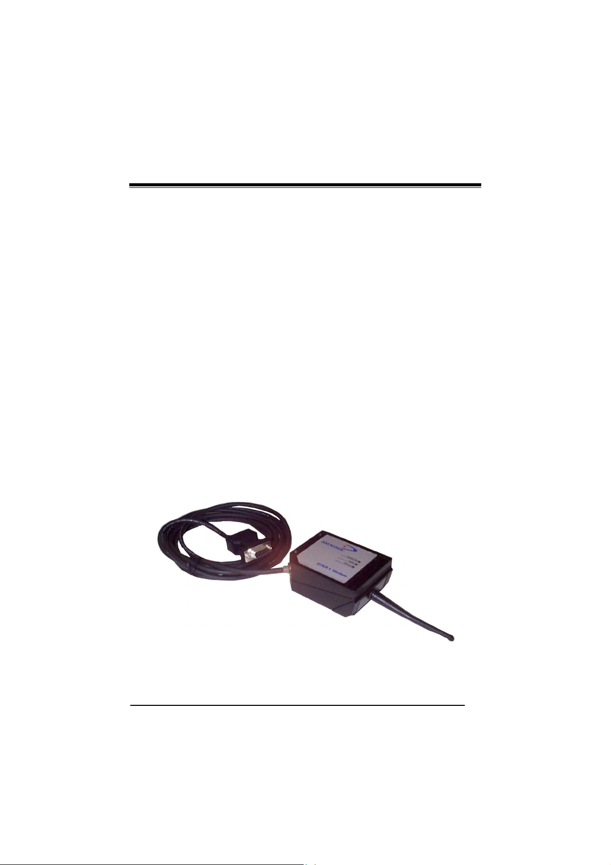
STARModem™
RADIO MODEM
QUICK REFERENCE
1
Page 8
UK/US
STARModem™
USING STARModem™
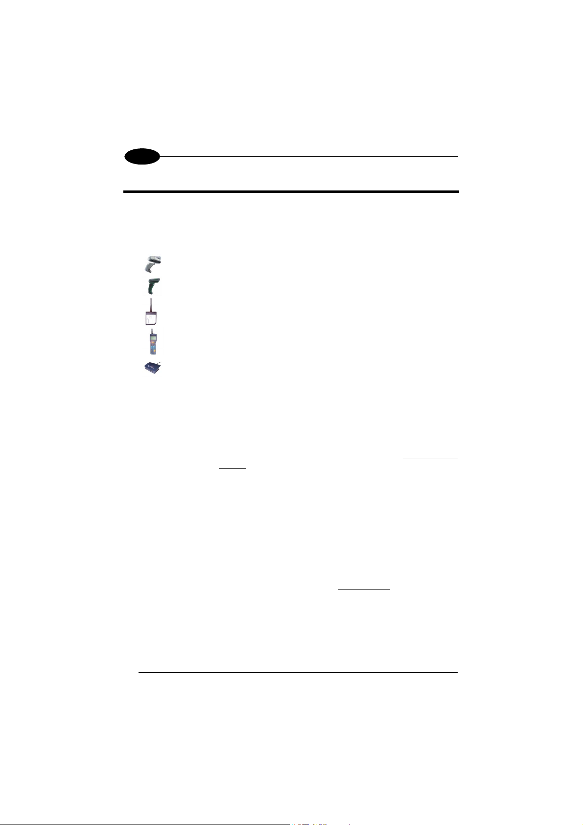
STARModem™ is a radio modem developed to provide wireless
433 MHz (European models) / 910 MHz (USA models) RF communication between
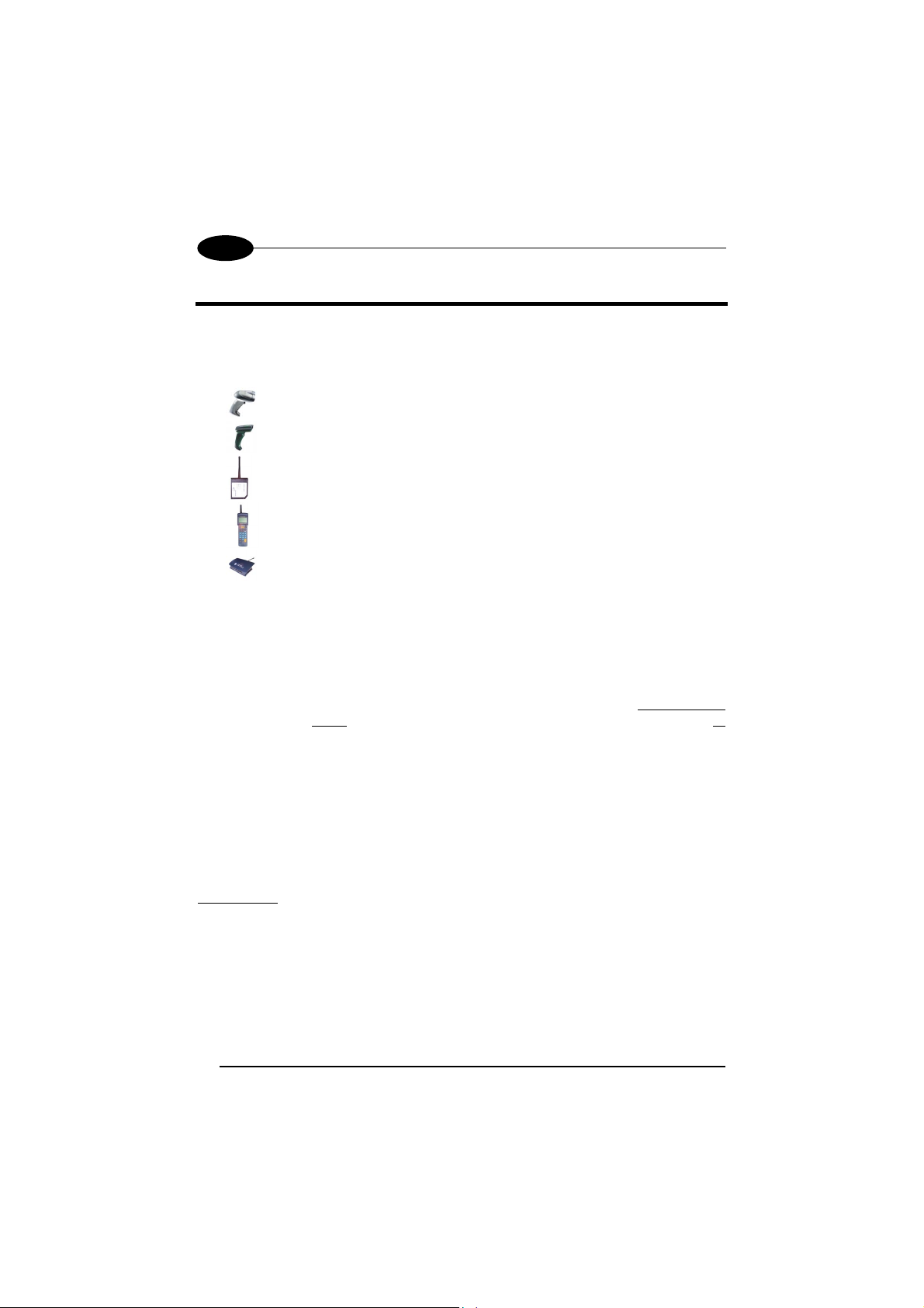
any serial device (Host) and Datalogic RF devices or base stations, such as:
-
-
-
-
-
* not compatible with STARModem™ USA models.
STARModem™ can be used in two different modes: Stand Alone mode and
STAR-System™ mode.
In Stand Alone mode, STARModem™ can be setup in uni-directional
communication to either receive (Server) data via radio from Datalogic RF devices, or
transmit (Client) data via radio to Datalogic RF devices. When working as Server,
currently supported devices are RF hand-held readers, another STARModem™ or
RF terminals loading STAR&Play™ software. All the multistandard interface
selections are valid (RS232, Wedge, Pen Emulation).
When working as Client, currently supported devices are another STARModem™
or a Datalogic OM-cradle. The only valid interface selection in RS232.
In Stand Alone mode, the system implements a different RF Narrow Band radio
protocol than STAR-System™.
In STAR-System™ mode, STARModem™ uniquely provides a wireless
bi-directional
STARModem™ is connected to the Host only through the RS232 interface.
For more details about the modem configuration options refer to the
STARModem™ Reference Manual provided on the installation CD-ROM.
Gryphon™ M Readers
Dragon™ M Laser Scanners
STARModem™ Radio Modems
Formula Basic Line RF Terminals (F734-E/RF, F725-E/RF, F660-E/RF)*
STARGATE™ Base Stations
communication between the Host and the RF devices.
2
Page 9
DATALOGIC
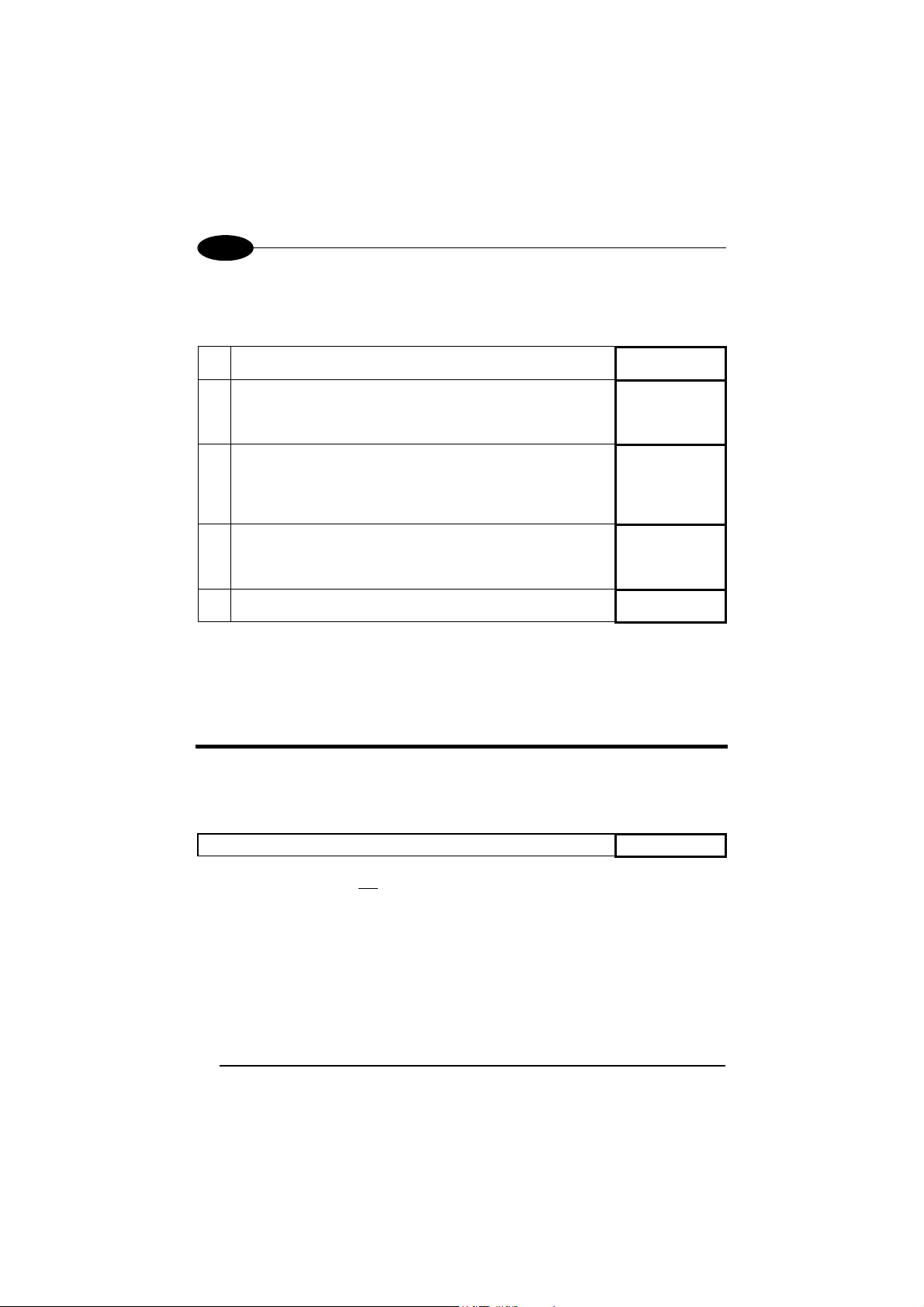
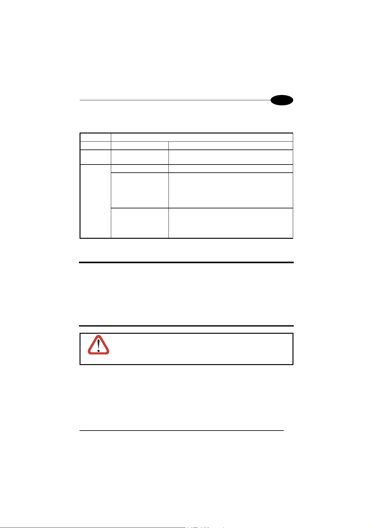
The LEDs signal the STARModem™ functioning, as described in the following
table:
LED DESCRIPTION
Power On Green constant STARModem™ is powered.
TX/RX Yellow blinking STARModem™ is receiving or transmitting data.
Off STARModem™ is working correctly. Status
Red constant
Red blinking
-
at startup, after firmware upload, it indicates that
the system is working with default configuration.
-
during normal functioning it signals a wrong
connection to the Host.
-
it blinks during a programming command
execution.
-
It blinks once when STARModem™ radio
transaction fails.
UK/US
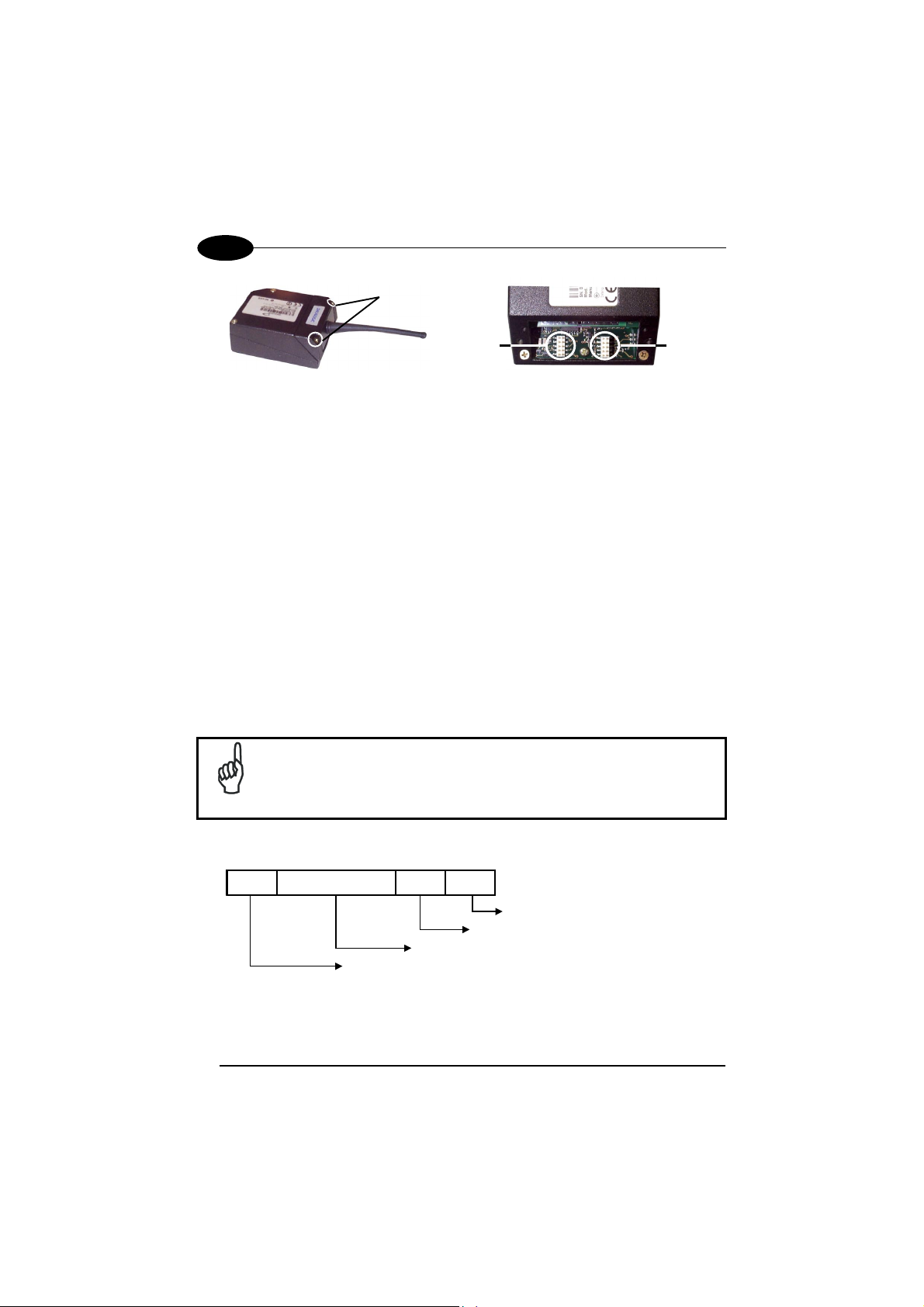
INSTALLATION
STARModem™ can be installed to operate in different positions by means of two
mounting brackets and an adjustable antenna.
The four screw holes (M4 x 5) on the body of the modem are for mechanical fixture.
See "Antenna", "Mounting Brackets" and "Overall Dimensions" at the end of this
Quick Reference Manual for more details.
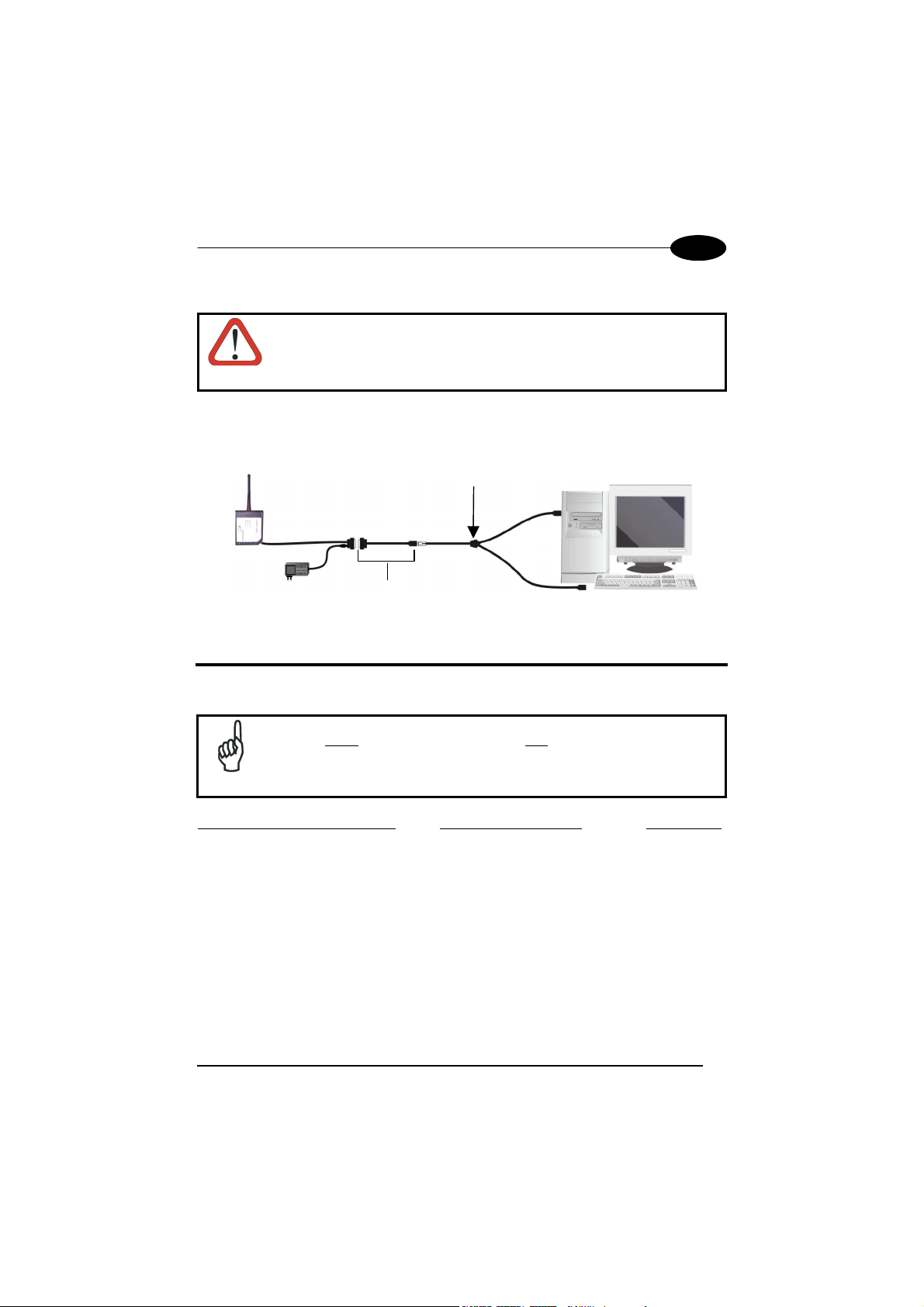
SYSTEM CONNECTIONS
CAUTION
STARModem™ can be connected to the Host through the dedicated 9-pin female
connector, or by means of an adapter and the Datalogic standard cable
corresponding to the desired interface. In addition, a power supply must be
connected to the power jack provided on the same connector.
See "STARModem™ Cable Pinout" at the end of this Quick Reference Manual for
more details.
3
Connections should always be made with power off!
Page 10
UK/US
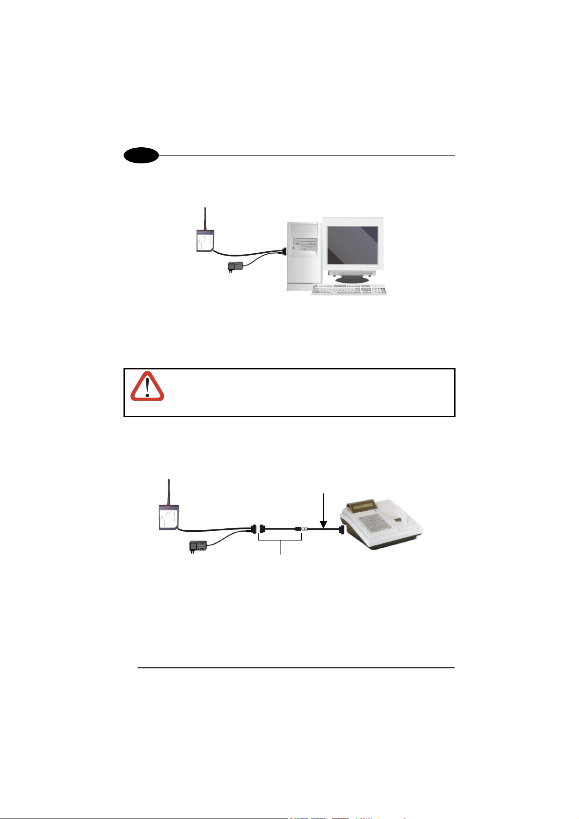
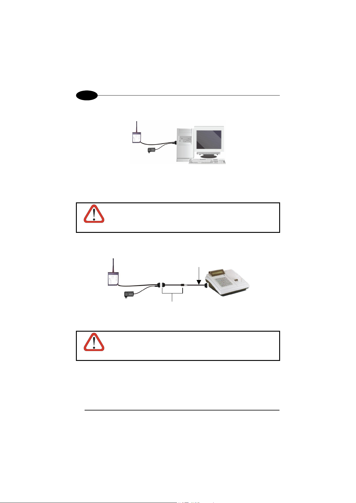
RS232 INTERFACE CONNECTION
STARModem™
Connect the modem cable directly to the PC COM Port.
PEN EMULATION INTERFACE CONNECTION
Before proceeding with this connection, configure STARModem™
software parameters through the RS232 interface and then set the
CAUTION
hardware jumper position (see "STAR
For Pen Emulation interface connection, it is necessary to use the adapter as shown
in the following figure:
Datalogic Standard Pen Emulation Cable
90ACC1859
STARModem™ Adapter
Modem™ Configuration").
4
Page 11
DATALOGIC
UK/US
WEDGE INTERFACE CONNECTION
Before proceeding with this connection, configure STARModem™
software parameters through the RS232 interface and then set the
CAUTION
For Wedge interface connection, it is necessary to use the adapter as shown in the
following figure:
hardware jumper position (see "STAR
Datalogic Standard Wedge Cable
90ACC1859
Modem™ Configuration").
STARModem™ Adapter
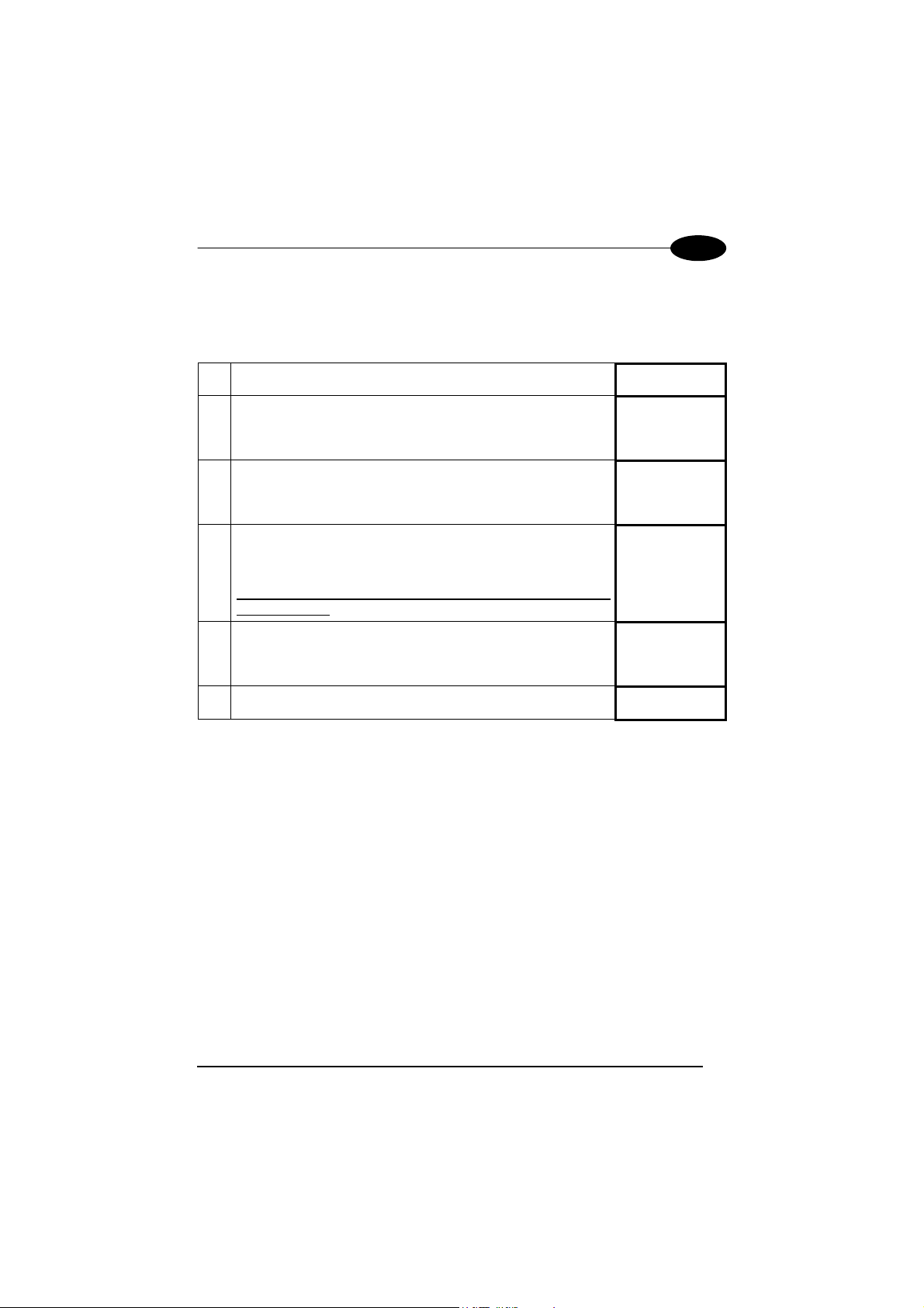
STARModem™ INITIAL SETUP
For a correct STARModem™ configuration keep in mind the following guidelines.
When using the modem for the first time, set the desired
STARModem™ address via RS232 serial interface, since its factory
NOTE
For Stand Alone configurations
set all parameters via RS232 interface using either the DL Sm@rtSet software
program or sending configuration strings to STARModem™. Then, set the correct
hardware jumper position as indicated in the table given in "STARModem™ Setup
For Stand Alone Mode" (see also the figure below).
For changing any configuration parameter in Wedge/Pen Emulation interface
connections, send the new configuration commands via radio using Datalogic RF
devices. Otherwise, set the jumper in the RS232 position (RS232 communication
parameters are set to default values) to send the configuration strings to
STARModem™ via serial interface and set the jumper back in the Wedge/Pen
Emulation position to enable this kind of connection.
default address is "Undefined".
using Wedge/Pen Emulation interface connections,
5
Page 12
UK/US
Screws
STARModem™
Position 1 Position 2
Position 1 = RS232/Digital interface
Position 2 = Wedge/Pen Emulation interface
STARModem™ configuration can be performed in three ways: by using the DL
Sm@rtSet software configuration program, by sending configuration strings from the
Host via the RS232 interface or by reading configuration barcodes with a Datalogic
RF device and sending the commands to STARModem™ via radio.
DL Sm@rtSet
DL Sm@rtSet is available on the STARModem™ CD-ROM and can be installed on
your PC.
DL Sm@rtSet is a Windows-based utility program providing a quick and user-friendly
configuration method via the RS232 interface.
It also allows upgrading the software of the connected device (see the DL Sm@rtSet
User's Manual for more details).
Configuration Strings
STARModem™ initial setup must be performed via serial interface by sending the
configuration strings to the modem using any terminal emulation program, for
example Hyper Terminal.
Ensure that your PC COM port is set as follows:
9600 baud, no parity, 8 data bits, 1 stop bit, handshaking disabled.
NOTE
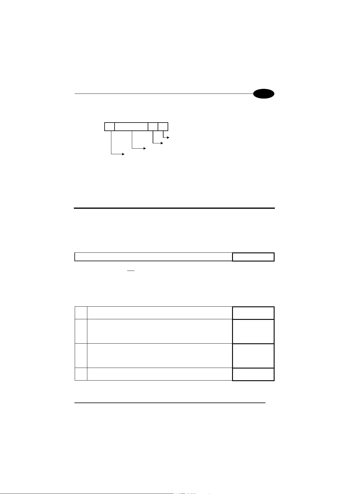
The programming sequence is the following:
$+
Command
Enter configuration environment
$-
Character sequence in following tables
CR
6
Carriage return character (0D Hex.)
Exit and Save configuration
Page 13
DATALOGIC
UK/US
Example
Command programming sequence:
$+ MA0RC1237 $- CR
Carriage return character (0D Hex.)
Exit and Save configuration
Enter configuration environment
STAR-Modem address in Stand Alone system: 1237
Each configuration parameter setting removes the condition previously active for that
parameter.
Refer to the STARModem™ Reference Manual for changing the default
parameters.
STARModem™ SETUP FOR STAND ALONE MODE
STAR Modem Receiver (Server)
RESTORE DEFAULT
Whenever necessary, send the following string to STARModem™ via RS232 to
restore its default values:
Restore STARModem™ Default
This command does not change the STARModem™ address nor the RF Baud
Rate parameters.
SET RADIO ADDRESS
Follow the procedure below to set the STARModem™ radio address and prepare it
to receive data from the RF devices of the system:
Enter Configuration
1.
$+$*CR
$+
2.
Set STARModem™ Radio Address
xxxx = four digits for the STARModem™ address (from
MA0RCxxxx
0000 to 1999). This address must be unique.
3.
Set RF Baud Rate (not for USA models)
x = 0 defines 9600 baud
MFx
1 defines 19200 baud
Exit and Save Configuration
4.
$-CR
7
Page 14
UK/US
STARModem™
INTERFACE SELECTION
Select the desired interface string for your application, then set the correct hardware
jumper position (see "STARModem™ Initial Setup" for jumper setting).
Among the following interface selection strings, send only the string that suits
your application:
RS232 Interface
$+CP0$-CR
Jumper
Position
1
Pen Emulation Interface
$+CP6$-CR
2
Wedge Interface
IBM AT or PS/2 PCs
IBM XT
PC Notebook
IBM SURE1
IBM Terminal 3153
$+CP500$-CR
$+CP503$-CR
$+CP505$-CR
$+CP506$-CR
$+CP504$-CR
2
2
2
2
2
IBM Terminals 31xx, 32xx, 34xx, 37xx
To select the interface for these IBM Terminals, send the correct KEY
TRANSMISSION string. Select the KEYBOARD TYPE if necessary (default =
advanced keyboard).
Make-only keyboard
Make-break keyboard
Advanced keyboard
Typewriter keyboard
$+CP502$-CR
$+CP501$-CR
$+FK1$-CR
$+FK0$-CR
2
2
2
2
ALT MODE
The ALT-mode selection allows barcodes sent to the PC to be interpreted correctly
independently from the Keyboard Nationality used. You do not need to make a
Keyboard Nationality selection.
(default = Num Lock Unchanged).
Make sure the Num Lock key on your keyboard is ON.
IBM AT- ALT mode
PC Notebook - ALT mode
Wyse Terminal - ANSI Keyboard
Wyse Terminal - PC Keyboard
Wyse Terminal - ASCII Keyboard
Wyse Terminal - VT2200 style Keyboard
APPLE ADB Bus
Digital Terminal VT2xx/3xx/4xx
$+CP507$-CR
$+CP508$-CR
$+CP509$-CR
$+CP510$-CR
$+CP511$-CR
$+CP514$-CR
$+CP513$-CR
$+CP512$-CR
2
2
2
2
2
2
2
1
8
Page 15
DATALOGIC
UK/US
For changing the configuration parameters when using the Digital
Terminal interface, send the new values via radio through Datalogic
RF devices. Otherwise, send the $+CP0$-CR string via radio to set
the RS232 interface and define the parameters via serial interface.
This operation sets the RS232 parameters to default values and
erases the current header and terminator selection. Thus, after
CAUTION
configuration setting, you must restore the Digital Terminal interface,
Header and Terminator selection by sending a command string
similar to the one given in the following example:
$+CP512EA0141EA1102$-CR.
If you selected the Wedge interface, you should also send among the following
strings the one the matches your Keyboard Nationality:
English
Deutsch
Svenskt
Français
Italiano
USA
Español
Belge
$+FJ4$-CR
$+FJ3$-CR
$+FJ5$-CR
$+FJ2$-CR
$+FJ1$-CR
$+FJ0$-CR
$+FJ6$-CR
$+FJ7$-CR
STAR Modem Transmitter (Client)
RESTORE DEFAULT
Whenever necessary, send the following string to STARModem™ via RS232 to
restore its default values:
Restore STARModem™ Default
This command does not change the STARModem™ address nor the address of
the Stand Alone destination device, nor the RF Baud Rate parameters.
$+$*CR
9
Page 16
UK/US
SET RADIO ADDRESS
Follow the procedure below to set the STARModem™ radio address and prepare it
to transmit data to the destination device of the system:
Enter Configuration
1.
2.
Set STARModem™ Radio Address
xxxx = four digits for the STARModem™ address (from
0000 to 1999). This address must be unique.
3.
Address of the Stand Alone Destination Device
xxxx = four digits for the address of the Stand Alone
Destination Device (from 0000 to 1999).
This address must be unique.
4.
Set RF Baud Rate (not for USA models)
x = 0 defines 9600 baud
1 defines 19200 baud
STARModem™
$+
MA0RCxxxx
MSxxxx
MFx
Exit and Save Configuration
5.
No interface selection is required, since STARModem™ can transmit data only if
connected to the Host via its RS232 serial interface.
$-CR
STARModem™ SETUP FOR STAR-System™ Mode
RESTORE DEFAULT
Whenever necessary, send the following string to STARModem™ via RS232 to
restore its default values:
Restore STARModem™ Default
This command does not change the STARModem™ address nor the
address of the STAR-System™ destination devices, nor the RF Baud Rate
parameters.
$+$*CR
10
Page 17
DATALOGIC
SET RADIO ADDRESSES
Follow the procedure below to set the STARModem™ radio address and prepare it
to receive and transmit data to all devices included in the range from the First to the
Last STAR-System™ destination device.
Enter Configuration
1.
2.
Set STARModem™ Radio Address
xxxx = four digits for the STARModem™ address (from
0000 to 1999). This address must be unique.
3.
First STAR-System™ Destination Device Address
xxxx = four digits for the Destination Device address (from
0000 to 1999).
4.
Last STAR-System™ Destination Device Address
xxxx = four digits for the Destination Device address (from
0000 to 1999).
If transmitting to one Destination device only, this selection
is not required.
5.
Set RF Baud Rate (not for USA models)
x = 0 defines 9600 baud
1 defines 19200 baud
MA1RCxxxx
UK/US
$+
MSxxxx
MTxxxx
MFx
Exit and Save Configuration
6.
When defining a range of destination device addresses, STARModem™ activates
roaming towards all the devices included within this range.
No interface selection is required, since all STAR-System™ transactions occur via
serial interface.
11
$-CR
Page 18

UK/US
STARModem™
STARModem™ DEFAULT CONFIGURATION
RS232 DEFAULT SETTINGS
9600 baud, parity disabled, 8 data bits, 1 stop bit, handshaking disabled, ACK/NACK
protocol disabled, inter-character delay disabled, 5 sec. rx timeout, FIFO enabled,
frame packing = frame + [CR].
PEN EMULATION DEFAULT SETTINGS
Interpret operating mode, minimum output pulse 600 µs, conversion to Code 39,
overflow medium, output level normal, idle level normal, inter-block delay disabled.
WEDGE DEFAULT SETTINGS
USA keyboard, caps lock off, num lock unchanged, inter-character and intercode
delay disabled, control character emulation = Ctrl + Shift + Key.
DATA FORMAT
Code identifier disabled, no header, terminator: RS232
header position = first frame field, code length tx not transmitted, address stamping
disabled, address delimiter disabled.
RADIO PARAMETERS
Transmission mode 1 way, radio protocol timeout 2 sec., single store disabled,
ACK/NACK from remote host disabled, RF baud rate 19200 (European models),
fixed RF baud rate 36800 (USA models), beacon disabled.
= CR-LF; WEDGE = ENTER,
WARRANTY
Datalogic warranties this product against defects in workmanship and materials, for a
period of 24 months from the date of shipment, provided that the product is operated
under normal and proper conditions.
Datalogic has the faculty to repair or replace the product, these provisions do not
prolong the original warranty term.
The warranty does not apply to any product that has been subject to misuse,
accidental damage, unauthorized repair or tampering.
12
Page 19
DATALOGIC
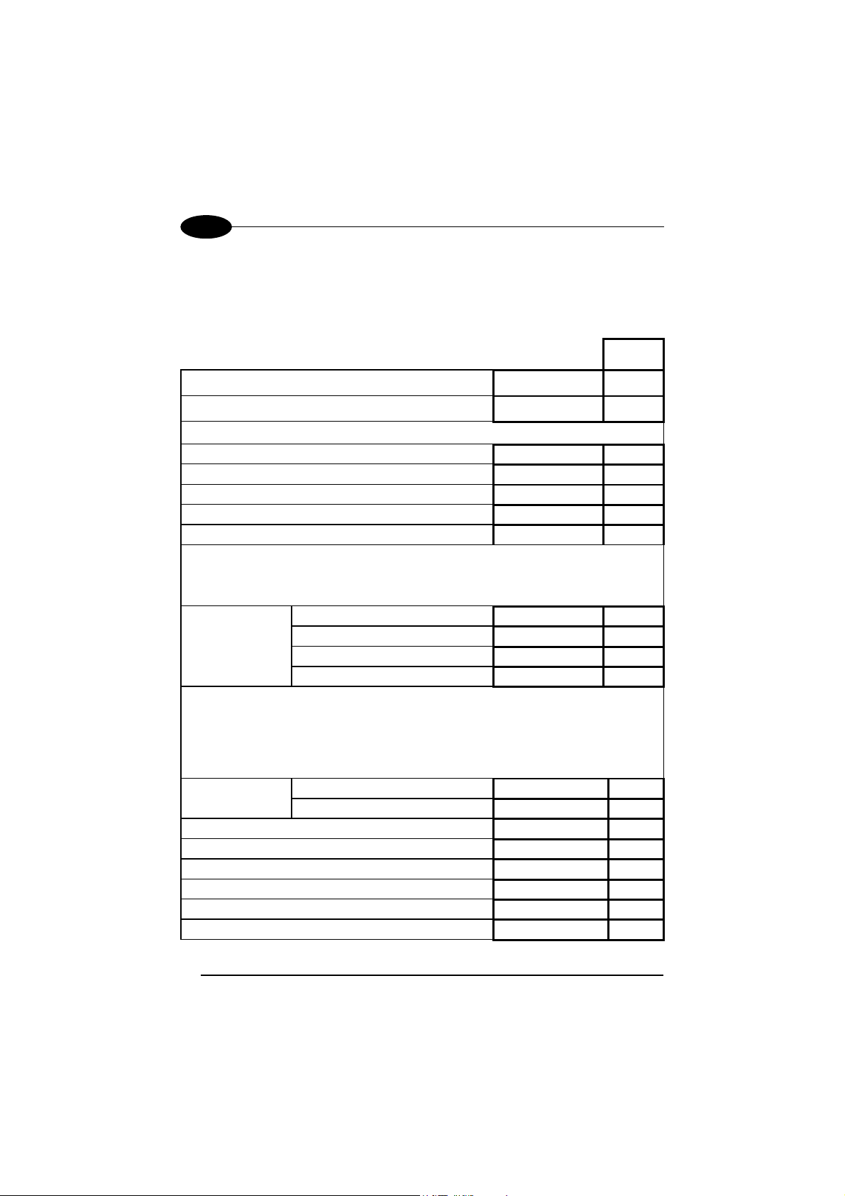
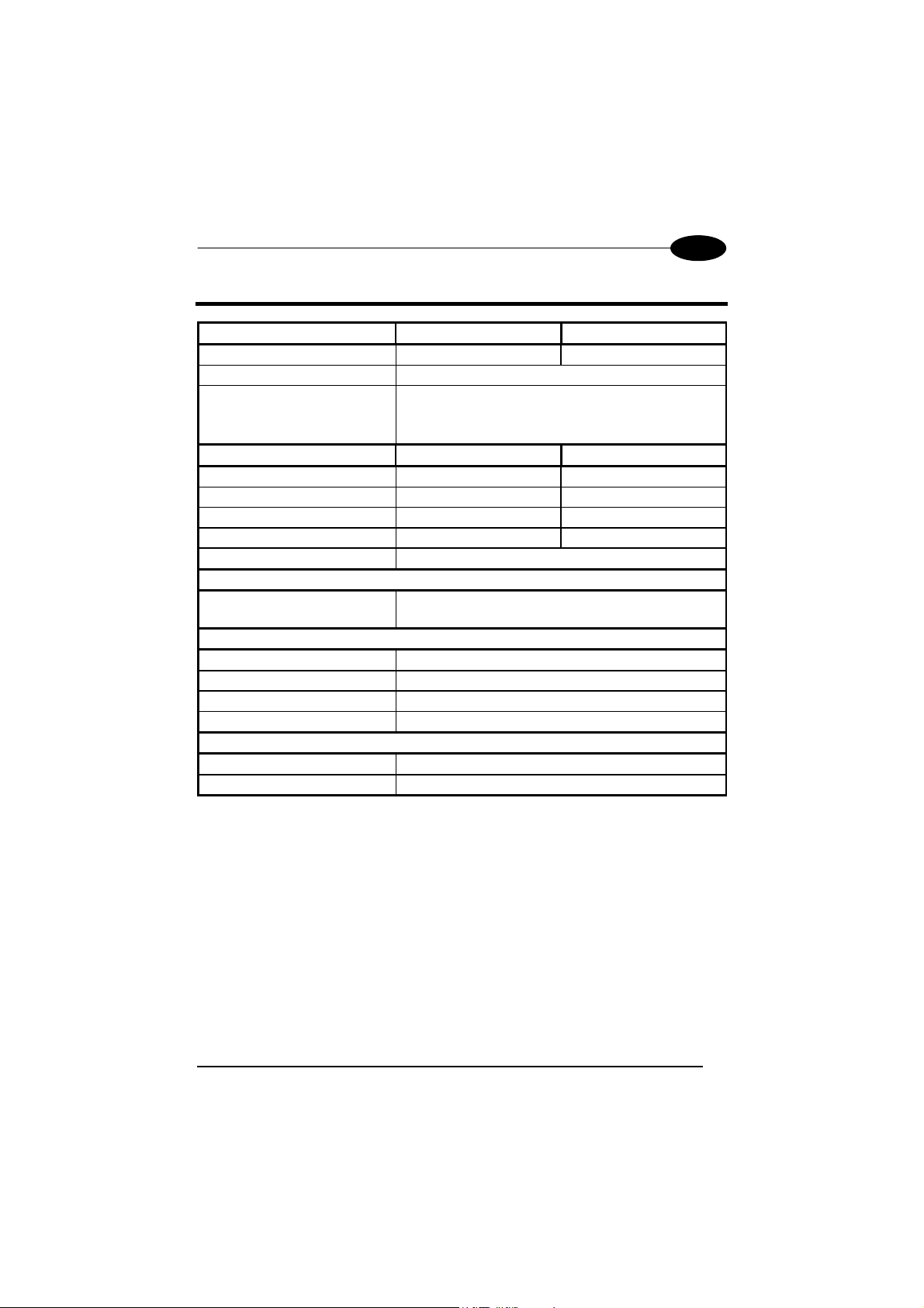
TECHNICAL FEATURES
Electrical Features 5 Volt Models 10 Volt Models
Supply voltage 5 Vdc ±5% 10 to 30 Vdc
Power consumption 2 W
Indicators Power On (green)
TX/RX (yellow)
Status (red)
Radio Features
Working frequency 433.92 Mhz 910 Mhz
Bit rate Up to 19200 baud 36800 baud
Effective Radiated Power <10 mW <1 mW
Range (in open air) 50 m / 164 ft 30 m / 98.4 ft
RF Modulation FSK
System Configuration
Maximum number of devices
per STARModem™
Environmental Features
Working temperature -20° to +50 °C / -4° to +122 °F
Storage temperature -20° to +70 °C / -4° to +158 °F
Humidity 90% non condensing
Protection class IP64
Mechanical Features
Weight 370 gr / 13.1 oz
Dimensions (without antenna) 68 x 84 x 34 mm / 2.68 x 3.3 x 1.3 in
European Models USA Models
32
UK/US
13
Page 20
UK/US
STARModem™
COMPLIANCE
This device must be opened by qualified personnel only.
Modifications or changes to this equipment without
expressed written approval of Datalogic could void the
authority to use the equipment.
This device complies with PART 15 of the FCC Rules.
Operation is subject to the following two conditions: (1)
This device may not cause harmful interference, and (2)
this device must accept any interference received,
including interference which may cause undesired
operation.
This equipment has been tested and found to comply with the limits for a Class B
digital device, pursuant to part 15 of the FCC Rules. These limits are designed to
provide reasonable protection against harmful interference in a residential
installation. This equipment generates, uses and can radiate radio frequency energy
and, if not installed and used in accordance with the instructions, may cause harmful
interference to radio communications. However, there is no guarantee that
interference will not occur in a particular installation. If this equipment does cause
harmful interference to radio or television reception, which can be determined by
turning the equipment off and on, the user is encouraged to try to correct the
interference by one or more of the following measures:
- Reorient or relocate the receiving antenna.
- Increase the separation between the equipment and receiver.
- Connect the equipment into an outlet on a circuit different from that to which the
receiver is connected.
- Consult the dealer or an experienced radio/TV technician for help.
STARModem™ is a Class III equipment according to the EN-60950 Electrical
Safety Standard.
DC supply voltage is 5 Vdc ±5% for 5 Volt models, 10 to 30 Vdc for 10-30 Volt
models, intended to be powered by a Class 2 power unit with a cable length
< 3m.
Contact the competent authority responsible for the management of radio frequency
devices of your country to verify the eventual necessity of a user license.
Refer to the web site http://europa.eu.int/comm/enterprise/rtte/spectr.htm for further
information.
14
Page 21

STARModem™
MODEM RADIO
GUIDA RAPIDA
15
Page 22
I
STARModem™
STARModem™ - DESCRIZIONE E USO
Il modem radio STARModem™ è stato sviluppato per fornire una comunicazione
via radio a 433 MHz (modelli europei) / 910 MHz (modelli USA) tra un apparecchio
seriale (es. Host PC) e prodotti radio Datalogic come lettori, terminali portatili e
stazioni base:
-
-
-
-
-
* non compatibili con i modelli USA di STARModem™.
STARModem™ può essere utilizzato in due diverse modalità: Stand Alone e
STAR-System™.
In modalità Stand Alone, STARModem™ può comunicare in modo unidirezionale
ricevendo dati (Server) oppure
Funzionando come Server, gli apparecchi Datalogic attualmente compatibili sono i
lettori radio, un altro STARModem™ oppure i terminali portatili che supportano il
software STAR&Play™. In questo caso è possibile utilizzare tutti i tipi di interfaccia
standard (RS232, Pen, Wedge).
Funzionando come Client, STARModem™ può comunicare con un altro
STARModem™ oppure con un cradle OM Datalogic utilizzando solamente
l’interfaccia seriale RS232.
In modalità Stand Alone, il sistema implementa un protocollo radio RF Narrow Band
diverso da quello di STAR-System™.
In modalità STAR-System™, STARModem™, collegato all’Host via seriale,
fornisce esclusivamente una comunicazione radio bi-direzionale
apparecchi radio.
Per ulteriori dettagli sulle opzioni relative alla configurazione del modem vedi lo
"STARModem™ Reference Manual" disponibile sul CD-ROM di installazione.
Lettori Gryphon™ M
Pistole Laser Dragon™ M
Modem Radio STARModem™
Terminali Radio Formula della Basic Line(F734-E/RF, F725-E/RF, F660E/RF)*
Base radio STARGATE™
trasmettendo dati (Client) ai prodotti radio Datalogic.
tra l’Host e gli
16
Page 23
DATALOGIC
I LED segnalano il funzionamento dello STARModem™ come descritto nella
seguente tabella:
LED DESCRIZIONE
Power On Verde acceso STARModem™ è alimentato.
TX/RX Giallo lampeggiante STARModem™ sta ricevendo o trasmettendo
dati.
Spento STARModem™ funziona correttamente Status
Rosso acceso
Rosso lampeggiante
-
all'avvio successivo al caricamento del
firmware, indica che il sistema sta lavorando
con la configurazione di default.
-
durante il normale funzionamento indica un
errore nella connessione all'Host.
-
lampeggia durante l'esecuzione di un
comando di programmazione.
-
lampeggia una volta quando la transazione
radio avviata da STARModem™ fallisce.
I
INSTALLAZIONE
Grazie a due staffe di montaggio ed ad un antenna orientabile lo STARModem™
può operare in diverse posizioni.
I quattro fori presenti sul corpo del modem garantiscono il fissaggio meccanico.
Vedi le sezioni "Antenna", "Mounting Brackets" e "Overall Dimensions" alla fine di
questa Guida Rapida per ulteriori dettagli.
SISTEMA RADIO - COLLEGAMENTO
Effettuate i collegamenti quando gli apparecchi non sono
alimentati.
ATTENZIONE
STARModem™ può essere collegato ad un Host attraverso il connettore 9 poli
femmina oppure utilizzando un adattatore ed i cavi standard Datalogic corrispondenti
all'interfaccia desiderata. Inoltre, un alimentatore deve essere collegato al jack di
alimentazione fornito sullo stesso connettore a 9 poli.
Vedi la sezione "STARModem™ Cable Pinout" alla fine di questa Guida Rapida
per ulteriori informazioni.
17
Page 24
I
CONNESSIONE CON INTERFACCIA RS232
STARModem™
Collegate direttamente il cavo alla COM Port del vostro Host.
CONNESSIONE CON INTERFACCIA PEN
Prima di effettuare questa connessione, configurate i parametri
software di STAR
posizionate correttamente il jumper (ponticello). Vedi la sezione
ATTENZIONE
Per effettuare una connessione con interfaccia Pen, è necessario utilizzare
l'adattatore come indicato nella figura seguente:
"Configurazione di STAR
Adattatore di STARModem™
Modem™ attraverso l'interfaccia RS232; poi,
Modem™".
Cavo Standard Datalogic per Pen
90ACC1859
CONNESSIONE CON INTERFACCIA WEDGE
Prima di effettuare questa connessione, configurate i parametri
software di STAR
posizionate correttamente il jumper (ponticello). Vedi la sezione
ATTENZIONE
Per effettuare una connessione con interfaccia Wedge, è necessario utilizzare
l'adattatore come indicato nella figura seguente.
"Configurazione di STAR
Modem™ attraverso l'interfaccia RS232; poi,
Modem™".
18
Page 25

DATALOGIC
I
Cavo Standard Datalogic per Wedge
90ACC1859
Adattatore STARModem™
CONFIGURAZIONE PRELIMINARE DI STARModem™
Per configurare correttamente STARModem™ occorre tenere presente le seguenti
indicazioni.
Utilizzando il modem per la prima volta, impostare l'indirizzo di
STAR
NOTA
predefinito alla consegna è "Undefined".
In configurazioni Stand Alone, durante le connessioni con interfaccia Wedge/Pen,
impostare tutti i parametri via seriale usando il programma DL Sm@rtSet oppure
inviando le stringhe di configurazione allo STARModem™. Successivamente,
posizionare correttamente il jumper come indicato nella tabella della sezione
"STARModem™ in Sistemi Stand-Alone" (vedi inoltre la figura sotto).
Per cambiare i parametri di configurazione nelle connessioni con interfaccia
Wedge/Pen, inviare i nuovi comandi di configurazione via radio attraverso gli
apparecchi RF Datalogic. Oppure, mettere il jumper in posizione RS232 (i parametri
di comunicazione RS232 verranno ripristinati con i valori di default) per inviare le
stringhe di configurazione allo STARModem™ via seriale. Infine, riportare il jumper
in posizione Wedge/Pen per attivare la comunicazione.
Modem™ desiderato via interfaccia seriale, poiché l'indirizzo
Viti
Posizione 2
Posizione 1
Posizione 1 = interfaccia RS232/Digital
Posizione 2 = interfaccia Wedge/Pen
STARModem™ può essere configurato in tre modi: utilizzando il programma di
configurazione DL Sm@rtSet, inviando le stringhe di configurazione dall'Host via
interfaccia RS232 oppure leggendo i codici a barre di configurazione con lettori RF
Datalogic e trasmettendo via radio al modem i relativi comandi.
19
Page 26

I
STARModem™
DL Sm@rtSet
DL Sm@rtSet è disponibile sul CD-ROM di STARModem™ e può essere installato
sul PC.
DL Sm@rtSet è un programma basato su Windows che consente di configurare in
modo veloce ed intuitivo il modem utilizzando l'interfaccia RS232. Inoltre, permette di
aggiornare il software sull'apparecchio connesso all'Host (vedi "DL Sm@rtSet User's
Manual" per ulteriori informazioni).
Stringhe di Configurazione
La configurazione preliminare di STARModem™ deve essere effettuata via seriale,
inviando al modem le stringhe di configurazione con qualsiasi programma di
emulazione di un terminale, come Hyper Terminal.
Assicurarsi che la COM Port del PC sia configurata come segue:
9600 baud, parità disabilitata, 8 bit di dato, 1 bit di stop, handshaking
NOTA
disabilitato.
La sequenza di programmazione è la seguente:
$+
Comando
Sequenza dei caratteri nelle seguenti tabelle
Inizio della configurazione
CR
$-
Carattere carriage return (0D Hex.)
Termine e salvataggio della configurazione
Esempio
Sequenza di programmazione di un comando:
$+ MA0RC1237 $- CR
Carattere carriage return (0D Hex.)
Termine e salvataggio della configurazione
Indirizzo di STARModem™ in sistema Stand-Alone: 1237
Inizio della configurazione
Impostando la configurazione di un parametro verrà rimossa la condizione
precedentemente attiva per lo stesso.
Vedi "STARModem™ Reference Manual" per modificare i parametri di default.
20
Page 27
DATALOGIC
I
CONFIGURAZIONE DI STARModem™ IN MODALITÀ
STAND-ALONE
STARModem™ Ricevitore (Server)
RIPRISTINO DEL DEFAULT
Se necessario, è possibile inviare la seguente stringa a STARModem™ attraverso
l'interfaccia RS232 per ripristinare i valori di default:
STARModem™ Default
Questo comando non ripristina il valore di default dell'indirizzo dello
STARModem™ e del parametro Baud Radio.
IMPOSTAZIONE DELL’INDIRIZZO RADIO
Seguire la procedura per impostare l’indirizzo radio di STARModem™ ed attivare
la ricezione di dati dagli apparecchi radio presenti nel sistema:
Inizio della Configurazione
1.
2.
Attribuzione Indirizzo radio a STARModem™
xxxx = quattro cifre per l'indirizzo di STARModem™ (da
0000 a 1999). L'indirizzo deve essere univoco.
$+$*CR
$+
MA0RCxxxx
3.
Impostazione Baud Radio (non valido per modelli USA)
x = 0 corrisponde a 9600 baud
1 corrisponde a 19200 baud
Termine e Salvataggio della Configurazione
4.
SELEZIONE DELL'INTERFACCIA
Inviate la stringa dell'interfaccia richiesta dalla vostra applicazione e posizionate
correttamente il jumper (vedi la sezione "Configurazione Preliminare
STARModem™" per le impostazioni del jumper).
Tra le stringhe seguenti, inviate solo la stringa corrispondente al modo di
comunicazione desiderato:
Interfaccia RS232
Interfaccia Pen
21
$+CP0$-CR
$+CP6$-CR
MFx
$-CR
Posizione
Jumper
1
2
Page 28

I
STARModem™
Interfaccia Wedge
IBM AT o PS/2 PCs
IBM XT
PC Notebook
IBM SURE1
IBM Terminal 3153
$+CP500$-CR
$+CP503$-CR
$+CP505$-CR
$+CP506$-CR
$+CP504$-CR
2
2
2
2
2
IBM Terminals 31xx, 32xx, 34xx, 37xx
Selezionate il codice KEY TRANSMISSION corretto (default = advanced
keyboard). Se necessario, selezionate anche il KEYBOARD TYPE.
Make-only keyboard
Make-break keyboard
Advanced keyboard
Typewriter keyboard
$+CP502$-CR
$+CP501$-CR
$+FK1$-CR
$+FK0$-CR
2
2
2
2
ALT MODE
L'impostazione del seguente tipo di interfaccia consente una corretta
interpretazione dei codici a barre spediti al PC, indipendentemente dalla nazionalità
della tastiera. Non è necessario impostare la nazionalità della tastiera.
(default = Num Lock unchanged)
Assicuratevi che la funzione Bloc Num sulla Vostra tastiera sia stata attivata.
IBM AT- ALT mode
PC Notebook - ALT mode
Wyse Terminal - ANSI Keyboard
Wyse Terminal - PC Keyboard
Wyse Terminal - ASCII Keyboard
Wyse Terminal - VT2200 style Keyboard
APPLE ADB Bus
Digital Terminal VT2xx/3xx/4xx
$+CP507$-CR
$+CP508$-CR
$+CP509$-CR
$+CP510$-CR
$+CP511$-CR
$+CP514$-CR
$+CP513$-CR
$+CP512$-CR
2
2
2
2
2
2
2
1
Per cambiare i parametri di configurazione durante una
connessione con interfaccia Digital Terminal, si possono inviare i
nuovi valori via radio con i lettori RF Datalogic. Oppure, inviare via
radio la stringa $+CP0$-CR per impostare l'interfaccia RS232 e
definire i parametri via seriale. Quest'ultima procedura ripristina i
valori di default dei parametri RS232 e cancella la selezione del
ATTENZIONE
preambolo e del postambolo. Per tale ragione, una volta impostata
la configurazione, è necessario ridefinire l'interfaccia Digital
Terminal, il preambolo ed il postambolo inviando una stringa simile
a quella riportata nell'esempio seguente:
$+CP512EA0141EA1102$-CR.
22
Page 29

DATALOGIC
I
Se avete impostato l'interfaccia Wedge, dovreste anche inviare, fra la stringhe che
seguono, la stringa per la selezione della Nazionalità della Tastiera:
English
Deutsch
Svenskt
Français
Italiano
USA
Español
Belge
$+FJ4$-CR
$+FJ3$-CR
$+FJ5$-CR
$+FJ2$-CR
$+FJ1$-CR
$+FJ0$-CR
$+FJ6$-CR
$+FJ7$-CR
STARModem™ Trasmettitore (Client)
RIPRISTINO DEL DEFAULT
Se necessario, è possibile inviare la seguente stringa a STARModem™ attraverso
l'interfaccia RS232 per ripristinare i valori di default:
STARModem™ Default
Questo comando non ripristina il valore di default dell'indirizzo di STARModem™,
dell’indirizzo dell’apparecchio Stand Alone destinatario e del parametro Baud Radio.
IMPOSTAZIONE DELL’INDIRIZZO RADIO
Seguire la procedura per impostare l’indirizzo radio di STARModem™ ed attivare
la trasmissione dati all’apparecchio Stand Alone destinatario presente nel sistema:
Inizio della Configurazione
1.
$+$*CR
$+
2.
Attribuzione Indirizzo radio a STARModem™
xxxx = quattro cifre per l'indirizzo di STARModem™ (da
MA0RCxxxx
0000 a 1999). L'indirizzo deve essere univoco.
3.
Attribuzione Indirizzo all’Apparecchio Stand Alone Destinatario
xxxx = quattro cifre per l'indirizzo dell’apparecchio destinatario
MSxxxx
(da 0000 a 1999). L'indirizzo deve essere univoco.
4.
Impostazione Baud Radio (non valido per modelli USA)
x = 0 corrisponde a 9600 baud
MFx
1 corrisponde a 19200 baud
Termine e Salvataggio della Configurazione
5.
23
$-CR
Page 30

I
STARModem™
CONFIGURAZIONE DI STARModem™ IN MODALITÀ
STAR-System™
RIPRISTINO DEL DEFAULT
Se necessario, è possibile inviare la seguente stringa a STARModem™ attraverso
l'interfaccia RS232 per ripristinare i valori di default:
STARModem™ Default
Questo comando non ripristina il valore di default dell'indirizzo di STARModem™,
degli indirizzi degli apparecchi destinatari e del parametro Baud Radio.
IMPOSTAZIONE DELL’INDIRIZZO RADIO
Seguire la procedura per impostare l’indirizzo radio di STARModem™ ed attivare
sia la ricezione che la trasmissione di dati agli apparecchi destinatari inclusi nella
fascia di indirizzi definita dal Primo e dall’Ultimo apparecchio destinatario STARSystem™:
Inizio della Configurazione
1.
2.
Attribuzione Indirizzo Radio a STARModem™
xxxx = quattro cifre per l'indirizzo di STARModem™ (da
0000 a 1999). L'indirizzo deve essere univoco.
$+$*CR
$+
MA1RCxxxx
3.
Attribuzione Indirizzo al primo Apparecchio Destinatario
xxxx = quattro cifre per l'indirizzo dell'Apparecchio
Destinatario (da 0000 a 1999).
4.
Attribuzione Indirizzo all'ultimo Apparecchio Destinatario
xxxx = quattro cifre per l'indirizzo dell'Apparecchio
Destinatario (da 0000 a 1999).
Se la trasmissione è verso un unico apparecchio
destinatario, questa selezione non è richiesta.
5.
Impostazione Baud Radio (non valido per modelli USA)
x = 0 corrisponde a 9600 baud
1 corrisponde a 19200 baud
Termine e Salvataggio della Configurazione
6.
La definizione di una fascia di indirizzi per gli apparecchi destinatari permette a
STARModem™ di effettuare un roaming verso tutti gli apparecchi con un indirizzo
compreso nella fascia stessa.
Non è richiesta la selezione dell'interfaccia, dal momento che tutte le transazioni
all'interno di STAR-System™ avvengono via seriale.
24
MSxxxx
MTxxxx
MFx
$-CR
Page 31

DATALOGIC
I
STARModem™ - CONFIGURAZIONE DI DEFAULT
CONFIGURAZIONE INTERFACCIA RS232
9600 baud, parità disabilitata, 8 bit di dato, 1 bit di stop, handshaking disabilitato,
protocollo ACK/NACK disabilitato, ritardo intercarattere disabilitato, timeout ricezione
5 sec., FIFO abilitato, frame packing = frame + [CR].
CONFIGURAZIONE INTERFACCIA EMULAZIONE PENNA
Modalità operativa interprete, impulso minimo 600 µs, conversione in Code 39,
overflow medio, livello di uscita normale, livello a riposo normale, ritardo interblocco
disabilitato.
CONFIGURAZIONE INTERFACCIA WEDGE
Tastiera USA, caps lock inattivo, num lock invariato, ritardo intercarattere disabilitato,
ritardo intercodice disabilitato, gestione del carattere di controllo = Ctrl + Shift + tasto.
FORMATO DEI DATI
Identificatore del codice disabilitato, nessun preambolo, postambolo: RS232
LF; WEDGE
trasmissione della lunghezza del codice, address stamping disabilitato, address
delimiter disabilitato.
PARAMETRI RADIO
Modalità di trasmissione 1 way, timeout del protocollo radio 2 sec., single store
disabilitato, ACK/NACK da host remoto disabilitato, baud radio 19200 (modelli
europei), baud radio fissa 36800 (modelli USA),beacon disabilitato.
= ENTER, posizione preambolo = primo campo del frame, nessuna
= CR-
GARANZIA
Datalogic garantisce questo prodotto contro difetti di fabbricazione e di materiali per
24 mesi dalla data della consegna, a condizione che il prodotto sia utilizzato come
previsto.
Datalogic si riserva la facoltà di riparare o sostituire il prodotto. Quanto sopra non
prolunga la garanzia originale.
La garanzia non si applica a prodotti utilizzati in modo corretto, danneggiati
accidentalmente, sottoposti a riparazioni non autorizzate o manomessi.
25
Page 32

I
STARModem™
CARATTERISTICHE TECNICHE
Caratteristiche Elettriche
Modelli 5 Volt
Tensione di alimentazione 5 Vdc ±5% da 10 a 30 Vdc
Potenza assorbita in carica 2 W
Indicatori Power On (verde)
Caratteristiche Radio
Modelli europei Modelli USA
Frequenza di lavoro 433.92 Mhz 910 Mhz
Bit rate fino a 19200 baud 36800 baud
Potenza effettiva emessa <10 mW <1 mW
Portata (in assenza di ostacoli) 50 m 30 m
RF Modulazione FSK
Configurazione di Sistema
Numero massimo di dispositivi
collegati allo stesso STARModem™
Caratteristiche Ambientali
Temperatura di lavoro -20° to +50 °C
Temperatura di immagazzinamento -20° to +70 °C
Umidità 90% senza condensa
Classe di protezione IP64
Caratteristiche Meccaniche
Peso 370 gr
Dimensioni (senza antenna) 68 x 84 x 34 mm
Modelli 10-30 Volt
TX/RX (giallo)
Status (rosso)
32
26
Page 33

DATALOGIC
I
CONFORMITÀ
Questo apparecchio può essere aperto solo da personale qualificato.
STARModem™ è un apparecchio Classe III in conformità con la norma EN-60950
Electrical Safety Standard.
Deve essere alimentato con un'unità di alimentazione Classe 2 avente una tensione
di alimentazione di 5 Vdc ±5% per i modelli 5 Volt e un'alimentazione compresa tra
10 - 30 Vdc per i modelli 10-30 Volt. Il cavo deve avere una lunghezza < 3m.
Prendi contatto con l'autorità competente per la gestione degli apparati a
radiofrequenza del tuo paese, per verificarne l'eventuale necessità della licenza
d'uso. Inoltre puoi trovare ulteriori informazioni al sito:
http://europa.eu.int/comm/enterprise/rtte/spectr.htm
27
Page 34

STARModem™
MODEM RADIO
GUIDE RAPIDE
28
Page 35

DATALOGIC
F
UTILISATION DE STARModem™
STARModem™ est un modem radio qui permet la communication par radio (433
MHz pour les modèles européens et 910 MHz pour les modèles USA) depuis un
appareil sériel (par ex. Host) vers des appareils radio Datalogic ou stations de base
radio, par exemple:
-
-
-
-
-
Gryphon™ M Lecteurs
Dragon™ M Pistolets Laser
STARModem™ Modems Radio
Formula Basic Line RF Terminals (F734-E/RF, F725-E/RF, F660-E/RF)*
STARGATE™ Stations de Base Radio
* non compatible avec les modèles USA de STARModem™.
STARModem™ peut être utilisé dans deux modalités différentes: mode monoposte
et mode STAR-System™.
En mode monoposte, STARModem™ active une communication unidirectionelle
pour recevoir les données (Serveur) ou pour transmettre les données (Client) aux
appareils radio Datalogic.
En fonctionnant comme un Serveur, STARModem™ peut communiquer avec les
pistolets radio, un autre STARModem™ ou les terminaux radio, qui chargent le
programme STAR&Play™, en utilisant toutes les interfaces standard (RS232,
Interclavier, Emulation Crayon).
En fonctionnant comme un Client, il peut communiquer avec un autre
STARModem™ ou une base radio OM Datalogic en utilisant seulement l’interface
RS232.
En mode monoposte, le système utilise un protocole radio RF Narrow Band qui est
différent de celui de STAR-System™.
En mode STAR-System™, STARModem™ permet uniquement une
communication radio bidirectionelle entre un Host et les appareils radio Datalogic.
STARModem™ peut être connecté à l’Host en utilisant seulement l’interface
RS232.
Se référer au "STARModem™ Reference Manual" consultable sur le CD-ROM
d'installation pour les détails relatifs aux options de configuration du modem.
29
Page 36

F
STARModem™
Les indicateurs signalent le fonctionnement de STARModem™, comme indiqué
dans le tableau suivant:
INDICATOR DESCRIPTION
Power On Vert permanent STARModem™ est alimenté.
TX/RX Jaune clignotant STARModem™ reçoit ou transmet les
données.
Désactivé STARModem™ fonctionne correctement. Status
Rouge permanent
-
au démarrage suivant le chargement du
microprogramme (firmware), il signale que le
système utilise la configuration par défaut.
-
pendant le fonctionnement normal, il signale
que la connexion au PC n'est pas correcte.
Rouge clignotant
-
il clignote pendant l'exécution d'une
commande de programmation.
-
il clignote une fois lorsque la transaction
effectuée par radio depuis le
STARModem™ échoue.
INSTALLATION
STARModem™ peut être installé en fonction de vos besoins à l’aide des deux
étriers pour le montage et d’une antenne directionnelle.
Les quatre trous (M4 x 5) sur le modem permettent sa fixation.
Se référer aux sections "Antenna", "Mounting Brackets" et "Overall Dimensions" à la
fin de ce guide pour plus de détails.
CONNEXION SYSTEME
Effectuer les connexions uniquement lorsque l'appareil n'est pas
sous tension.
ATTENTION
Vous pouvez connecter STARModem™ au Host au moyen du connecteur femelle
9-pin ou en utilisant un adaptateur et le câble standard Datalogic correspondant au
type d'interface choisie.
De plus, un boîtier d'alimentation doit être connectée au jack d'alimentation qui se
trouve dans le même connecteur.
Se référer à la section "STARModem™ Cable Pinout" à la fin de ce guide pour plus
de détails.
30
Page 37

DATALOGIC
CONNEXION RS232
F
Branchez le câble directement dans le port COM du PC.
CONNEXION EMULATION CRAYON
Avant de réaliser cette connexion, vous devez configurer les
paramètres du software STARModem™ via l'interface RS232 et
puis positionner le cavalier (jumper) correctement (se référer à la
ATTENTION
section " Configuration STAR
Pour effectuer la connexion émulation crayon, il est nécessaire d'utiliser l'adaptateur
(voir la figure ci-dessous):
Câble standard Emulation Crayon Datalogic
90ACC1859
Adaptateur STARModem™
Modem™ ").
31
Page 38

F
STARModem™
CONNEXION INTERCLAVIER
Avant de réaliser cette connexion, vous devez configurer les
paramètres du software STAR
puis positionner le cavalier (jumper) correctement (se référer à la
ATTENTION
Pour effectuer la connexion interclavier, il est nécessaire d'utiliser l'adaptateur (voir la
figure suivante):
section " Configuration STAR
Câble standard interclavier Datalogic
90ACC1859
Modem™ via l'interface RS232 et
Modem™ ").
Adaptateur STARModem™
CONFIGURATION INITIALE DE STARModem™
Pour configurer le STARModem™ correctement, il faut tenir compte des
indications suivantes.
En utilisant le modem pour la première fois, vous devez configurer
l'adresse radio du STARModem™ via l'interface RS232, étant donné
NOTE
En utilisant les connexions interclavier et émulation crayon dans une configuration
monoposte, vous pouvez configurer les paramètres de deux façons: soit en utilisant
le programme de configuration DL Sm@rtSet, soit en envoyant une séquence de
configuration au STARModem™. Ensuite, positionner le cavalier selon les
indications du tableau qui se trouve dans la section "STARModem™ dans un
Système Stand-Alone" (voir aussi la figure suivante).
Pour changer les paramètres de configuration dans une connexion interclavier ou
émulation crayon, vous pouvez envoyer les séquences de configurations par radio
en utilisant les appareils radio Datalogic. Ou bien, placer le cavalier en position
RS232 (les paramètres de communication de l'interface RS232 seront restaurés par
défaut) pour envoyer les séquences de configuration au STARModem™ via RS232.
Remettre ensuite le cavalier en position Interclavier/Emulation Crayon pour activer la
connexion.
que la valeur de l'adresse définie par défaut en usine est "Undefined”.
32
Page 39

DATALOGIC
Vis
F
Position 1 Position 2
Position 1 = Interface RS232/Digital
Position 2 = Interface Interclavier/Emulation Crayon
STARModem™ peut être configuré de trois façons: en utilisant le programme de
configuration DL Sm@rtSet, en envoyant les séquences de configuration depuis le
Host via l'interface RS232 ou en lisant les codes à barres de configuration avec les
appareils radio Datalogic et en les envoyant à STARModem™ par radio.
DL Sm@rtSet
DL Sm@rtSet est disponible sur le CD-ROM de STARModem™ et peut être
installé sur votre PC.
DL Sm@rtSet est un programme de configuration s’exécutant sous Windows
permettant des réglages et des mises au point simples et conviviales via l'interface
RS232. Il permet aussi de mettre à jour le logiciel de l'appareil connecté au Host (voir
"DL Sm@rtSet User's Manual" pour plus de détails).
Suites de Configuration
La configuration initiale de STARModem™ doit être effectuée en envoyant des
suites de configuration au modem en utilisant un programme d’émulation de terminal,
par exemple Hyper Terminal. Les suites sont envoyées depuis l’Host via l’interface
RS232.
Assurez-vous que le port COM est configuré comme suit:
9600 baud, parité désactivée, 8 bit de données, 1 bit de stop,
NOTE
"handshaking" désactivé.
La séquence de programmation est la suivante:
$+
33
Command
Chaîne de charactères dans les tableaux suivants
Initialisation de la configuration
CR
$
-
Charactère carriage return (0D Hex.)
Fin et enregistrement de la configuration
Page 40

F
A
STARModem™
Exemple
Séquence d'une commande de programmation:
$+ MA0RC1237 $- CR
Charactère carriage return (0D Hex.)
Fin et enregistrement de la configuration
dresse de STARModem™ dans système Stand Alone: 1237
Initialisation de la configuration
La configuration d'un paramètre remplace la condition qui était active précédemment.
Se référer au STARModem™ Reference Manual pour changer les paramètres par
défaut.
CONFIGURATION DE STARModem™ EN MODE
MONOPOSTE
STAR Modem Récepteur (Serveur)
RESTAURATION PAR DEFAUT
Si vous désirez restaurer les paramètres par défaut, vous pouvez envoyer la suite de
caractères suivante via l'interface RS232:
Restauration STARModem™ par Défaut
Cette commande ne restaure pas l'adresse de STARModem™ et le paramètre de
Baud Radio par défaut
.
SELECTION DE L'ADRESSE RADIO
En suivant la procédure ci-dessous, vous pouvez configurer le STARModem™
pour recevoir les données envoyées depuis les appareils radio du système:
Initialisation de la Configuration
1.
$+$*CR
$+
2.
Enregistrement de l'Adresse Radio de STARModem™
xxxx = quatre chiffres pour l'adresse de STARModem™
MA0RCxxxx
( de 0000 à 1999). Cette adresse doit être unique.
3.
Sélection Baud Radio (non valable pour les modèles USA)
x = 0 sélectionne 9600 baud
MFx
1 sélectionne 19200 baud
Fin et enregistrement de la configuration
4.
34
$-CR
Page 41

DATALOGIC
F
SELECTION DE L'INTERFACE
Envoyez la chaîne de programmation correspondant au mode de communication
désiré, puis placez le cavalier correctement (voir la section "Configuration
STARModem™" pour plus de détails relatifs à l'installation du cavalier).
Pour les chaînes de programmation suivantes, envoyer uniquement les chaînes
correspondantes au mode de communication désiré:
RS232
$+CP0$-CR
Position
Cavalier
1
Emulation Crayon
$+CP6$-CR
2
Interclavier
IBM AT ou PS/2 PCs
IBM XT
PC Notebook
IBM SURE1
IBM Terminal 3153
$+CP500$-CR
$+CP503$-CR
$+CP505$-CR
$+CP506$-CR
$+CP504$-CR
2
2
2
2
2
IBM Terminals 31xx, 32xx, 34xx, 37xx
Lire le code correct de KEY TRANSMISSION et, si nécessaire, lire le code
correspondant à votre clavier (défaut = advanced keyboard).
Make-only keyboard
Make-break keyboard
Advanced keyboard
Typewriter keyboard
$+CP502$-CR
$+CP501$-CR
$+FK1$-CR
$+FK0$-CR
2
2
2
2
ALT MODE
La sélection de l'interface suivante permet une interprétation correcte par le PC des
codes à barres transmis, indépendamment de la nationalité du clavier. Il n'est pas
nécessaire d'effectuer la sélection de la nationalité du clavier.
(défaut = Num Lock Unchanged)
Vérifiez que le pavé numérique soit activé sur votre clavier.
IBM AT- ALT mode
PC Notebook - ALT mode
Wyse Terminal - ANSI Keyboard
Wyse Terminal - PC Keyboard
Wyse Terminal - ASCII Keyboard
Wyse Terminal - VT2200 style Keyboard
APPLE ADB Bus
Digital Terminal VT2xx/3xx/4xx
$+CP507$-CR
$+CP508$-CR
$+CP509$-CR
$+CP510$-CR
$+CP511$-CR
$+CP514$-CR
$+CP513$-CR
$+CP512$-CR
2
2
2
2
2
2
2
1
35
Page 42

F
STARModem™
Pour changer les paramètres de configuration en utilisant l'interface
Digital terminal, envoyez les nouvelles valeurs au moyen des
appareils radio Datalogic par radio. Autrement, envoyer la chaîne
$+CP0$-CR par radio pour sélectionner l'interface RS232 et
configurer les paramètres via l'interface RS232. Cette opération
restaure les paramètres de l'interface RS232 par défaut et annule la
ATTENTION
sélection du "header" et du "terminator". Une fois la configuration
effectuée, vous devez restaurer l'interface Digital Terminal, le
"header" et le "terminator" en envoyant une chaîne de commande
similaire à l'exemple suivant:
$+CP512EA0141EA1102$-CR.
Si vous avez sélectionné l'interface interclavier, vous devez également envoyer
parmi les chaînes suivantes, celle de la nationalité de votre clavier:
English
Deutsch
Svenskt
Français
Italiano
USA
Español
Belge
$+FJ4$-CR
$+FJ3$-CR
$+FJ5$-CR
$+FJ2$-CR
$+FJ1$-CR
$+FJ0$-CR
$+FJ6$-CR
$+FJ7$-CR
STAR Modem Transmetteur (Client)
RESTAURATION PAR DEFAUT
Si vous désirez restaurer les paramètres par défaut, vous pouvez envoyer la suite de
caractères suivante via l'interface RS232:
Restauration STARModem™ par Défaut
Cette commande ne restaure pas l'adresse de STARModem™ et l’adresse de
l’appareil Stand Alone destinataire par défaut.
$+$*CR
36
Page 43

DATALOGIC
SELECTION DE L'ADRESSE RADIO
En suivant la procédure ci-dessous, vous pouvez configurer le STARModem™
pour transmettre les données à l’appareil Stand Alone destinataire du système:
Initialisation de la Configuration
1.
2.
Enregistrement de l'Adresse Radio de STARModem™
xxxx = quatre chiffres pour l'adresse de STARModem™
( de 0000 à 1999). Cette adresse doit être unique.
3.
Enregistrement de l'Adresse de l’Appareil Stand Alone
Destinataire
xxxx = quatre chiffres pour l'adresse de l’appareil
( de 0000 à 1999). Cette adresse doit être unique.
4.
Sélection Baud Radio (non valable pour les modèles USA)
x = 0 sélectionne 9600 baud
1 sélectionne 19200 baud
MA0RCxxxx
MSxxxx
F
$+
MFx
Fin et enregistrement de la configuration
5.
La sélection de l'interface n'est pas nécessaire, puisque STARModem™ doit être
connecté au Host en utilisant l'interface RS232 pour transmettre les données.
$-CR
CONFIGURATION DE STARModem™ EN MODE
STAR-System™
RESTAURATION PAR DEFAUT
Si vous désirez restaurer les paramètres par défaut, vous pouvez envoyer la suite de
caractères suivante via l'interface RS232:
Restauration STARModem™ par Défaut
Cette commande ne
adresses des appareils destinataires et le paramètre de Baud Radio.
restaure pas par défaut l'adresse de STARModem™, les
$+$*CR
37
Page 44
F
SELECTION DES ADRESSES RADIO
En suivant la procédure ci-dessous, vous pouvez configurer le STARModem™
pour recevoir ainsi que transmettre les données aux appareils inclus dans la plage
d’adresses définie entre le premier et le dernier appareil destinataire
STAR-System™.
Initialisation de la Configuration
1.
2.
Enregistrement de l'Adresse Radio de STARModem™
xxxx = quatre chiffres pour l'adresse de STARModem™
(de 0000 à 1999). Cette adresse doit être unique.
3.
Enregistrement de l'Adresse du premier Appareil
Destinataire STAR-System™
xxxx = quatre chiffres pour l'adresse de l'appareil
destinataire (de 0000 à 1999).
4.
Enregistrement de l'Adresse du dernier Appareil
Destinataire STAR-System™
xxxx = quatre chiffres pour l'adresse de l'appareil
destinataire (de 0000 à 1999).
Si la transmission est seulement vers un appareil, cette
sélection n'est pas nécessaire.
5.
Sélection Baud Radio (non valable pour les modèles USA)
x = 0 sélectionne 9600 baud
1 sélectionne 19200 baud
STARModem™
$+
MA1RCxxxx
MSxxxx
MTxxxx
MFx
Fin et enregistrement de la Configuration
6.
En sélectionnant une plage d’adresses pour les appareils destinataires,
STARModem™ active un service de roaming vers les appareils inclus dans cette
plage.
La sélection de l'interface n'est pas nécessaire, puisque les transactions dans le
STAR-System™ utilisent l'interface RS232.
38
$-CR
Page 45

DATALOGIC
F
STARModem™ - CONFIGURATION PAR DEFAUT
CONFIGURATION INTERFACE RS232
9600 baud, parité désactivé, 8 bit de données, 1 bit de stop, "handshaking"
désactivée, ACK/NACK depuis l’host désactivé, délai entre les caractères désactivé,
"rx timeout" 5 sec., FIFO activé, "frame packing" = frame + [CR]
CONFIGURATION INTERFACE EMULATION CRAYON
Mode opératoire interpréter, impulsion de sortie 600 µs, conversion en code 39,
"overflow" moyen, niveau de sortie normal, niveau au repos normal, délai entre les
blocs désactivé.
CONFIGURATION INTERFACE INTERCLAVIER
Clavier USA, "caps lock" inactif, pavé numérique inchangé, délai entre les caractères
et délai entre les codes désactivés, gestion du caractère de contrôle = Ctrl + Shift +
touche.
FORMAT DE DONNES
Code d’identification désactivé, aucun "header", "terminator": RS232
WEDGE
de la longueur du code désactivée, "address stamping" désactivé, "address delimiter"
désactivé.
PARAMETRES RADIO
Mode de transmission "1 way", timeout du protocole de la radio = 2 secondes, "single
store" désactivé, ACK/NACK depuis le remote host désactivé, 19200 baud radio
(modèles européens), 36800 fixe baud radio (modèles USA), "beacon" désactivé.
= ENTER, position de l’"header" = premier champ du "frame", transmission
= CR-LF;
GARANTIE
Datalogic garantit ce produit de tout défaut de fabrication ou des matériels pendant
les 24 mois qui suivent la date de livraison, à condition que le produit soit utilisé
correctement.
Datalogic a la possibilité de réparer ou de remplacer ce produit. Ces mesures ne
prolongeront pas l'échéance de la garantie.
La garantie ne s'applique pas aux produits qui ont été utilisés de façon incorrecte,
accidentellement endommagés ou soumis à des réparations non autorisées.
39
Page 46

F
STARModem™
CARACTERISTIQUES TECHNIQUES
Caractéristiques Électriques
Modèles 5 Volt
Tension 5 Vdc ±5% 10 à 30 Vdc
Consommation 2 W
Indicateurs Power On (vert)
Caractéristiques Radio
Modèles européens Modèles USA
Fréquence de fonctionnement 433.92 Mhz 910 Mhz
Transmission de données Jusqu'à 19200 baud 36800 baud
Energie réelle émise <10 mW <1 mW
Portée 50 m 30 m
Modulation RF FSK
Configuration du Système
Qté maximale d’appareils par
STARModem™
Caractéristiques Ambiantes
Température de fonctionnement -20° to +50 °C
Température de stockage -20° to +70 °C
Humidité 90% sans condensation
Classe de protection IP64
Caractéristiques Mécaniques
Poids 370 gr
Dimensions (sans antenne) 68 x 84 x 34 mm
Modèles 10-30Volt
TX/RX (jaune)
Status (rouge)
32
40
Page 47

DATALOGIC
F
CONFORMITE
L'appareil ne doit être ouvert que par une personne qualifiée.
STARModem™ est un appareil de Class III selon la norme EN-60950 Electrical
Safety Standard.
La tension a un valeur de 5 Vdc ±5% pour les modèles 5 Volt et est comprise dans la
plage de valeurs 10-30 Vdc pour les modèles 10-30 Volt. L'appareil doit être
connecté à un boîtier d'alimentation de Classe 2 avec une longueur du câble < 3 m.
Contactez l'autorité compétente en la gestion des appareils à radio fréquence de
votre pays pour vérifier la nécessité du permis d'usage. Pour tout renseignement
vous pouvez vous référer au site web:
http://europa.eu.int/comm/enterprise/rtte/spectr.htm
41
Page 48

STARModem™
RADIO MODEM
KURZANLEITUNG
42
Page 49

DATALOGIC
D
BESCHREIBUNG UND GEBRAUCHSANWEINSUNG
STARModem™ ist ein Funkmodem, und bietet eine zuverlässige 433 MHz
(Europäische Modelle) / 910 MHz (USA Modelle) Funkverbindung für
Datenübertragung zwischen einem seriellen Gerät (PC) und Datalogic Basisstationen
oder mobile Geräte wie zum Beispiel:
-
-
-
-
-
* nicht kompatible mit STARModem™ USA Modellen.
STARModem™ kann in zwei verschiedenen Moden verwendet werden:
Stand-Alone-Mode und STAR-System™ Mode.
Im Stand-Alone-Mode erlaubt das STARModem™ eine unidirektionaleÜbertragung, um Daten entweder zu empfangen (Server), oder auf andere Datalogic
Funkgeräte zu übertragen (Client).
Als Server, ist das STARModem™ kompatibel mit Funk-Lesegeräten, einem
anderen STARModem™ oder mobilen Terminals mit STAR&Play™ Software und
alle Standard Schnittstellen sind gültig (RS232, Lesestiftschnittstelle,
Tastaturschnittstelle).
Als Client, ist das STARModem™ kompatibel mit einem anderen STARModem™
oder mit einer Funkstation OM Datalogic. Die RS232 Schnittstelle ist die einzige
gültige Schnittstelle.
Im Stand-Alone-Mode verwendet das System ein anderes RF Narrow Band
Funkprotokoll als im STAR-System™ mode.
Im STAR-System™ Mode, ermöglicht das STARModem™ eine bidirektionale
Funkübertragung zwischen einem Host und der Funklesegeräte. Das
STARModem™ ist mit dem Host über die RS232 Schnittstelle verbunden.
Siehe "STARModem™ Reference Manual" für weitere Details. Das Handbuch ist
auf der Installations - CD verfügbar.
Gryphon™ M Lesegerät
Dragon™ M Laserscanner
STARModem™ Funk Modem
Formula Basic Line RF Laserterminal (F734-E/RF, F725-E/RF, F660-E/RF)*
STARGATE™ Basisstation
43
Page 50

D
Die LED-Anzeigen zeigen den Zustand des STARModem™. Siehe dazu folgende
Tabelle:
LED ZUSTAND
Power On grün STARModem™ ist versorgt.
TX/RX gelb blinkend STARModem™ sendet / empfängt Daten.
Status
aus Kein Fehler
rot ein
rot blinkend
-
beim Start nach dem Ladevorgang der
Firmware zeigt die LED, dass die Konfiguration
auf die Grundeinstellungen gesetzt wird.
-
beim Normalbetrieb zeigt die LED, dass der
Anschluss zum PC nicht richtig ist.
-
die LED zeigt die Ausführung eines
Kommandos.
-
die LED blinkt sobald die STARModem™
Funkübertragung nicht erflogreich ist.
STARModem™
INSTALLATION
Verwenden Sie die zwei Montagewinkel und die verstellbare Antenne um
STARModem™ zu installieren.
Vier Löcker (M4 x 5) auf dem Modem erlauben eine schnelle und einfache
Befestigung an der Wand.
Siehe "Antenna", "Mounting Brackets" und "Overall Dimensions" am Ende dieser
Kurzanleitung für weitere Details.
SYSTEMANSCHLUß
Kabel dürfen nur im ausgeschalteten Zustand angeschlossen
werden.
ACHTUNG
Ein 9-poliger Stecker (female) am Kabel des STARModem™ erlaubt die
Verbindung dem Host über RS232 Schnittstelle. Für Lesestift- und
Tastaturschnittstelle ist ein Adapter und ein Datalogic Standard-Kabel erforderlich.
Verbinden Sie auch den Anschlussstecker des externen Netzteils mit der
Netzteilbuchse am 9-poligen Stecker um das Modem zu versorgen.
Siehe "STARModem™ Cable Pinout" am Ende dieser Kurzanleitung für weitere
Details.
44
Page 51

DATALOGIC
RS232 - SCHNITTSTELLE
D
Stecken Sie das Kabel direkt am PC COM Port ein.
LESESTIFTSCHNITTSTELLE
Vor der Modemsinstallation sollten die Software Parameter über
RS232 Schnittstelle festgelegt werden. Der Jumper sollte in die
korrekte Position gesteckt werden (siehe Abschnitt
ACHTUNG
Der Adapter erlaubt den Anschluss an den Host über die Lesestiftschnittstelle. Siehe
dazu das folgende Bild:
"STAR
Modem™ Konfiguration").
Datalogic Standard Lesestift - Kabel
90ACC1859
STARModem™ Adapter
TASTATURSCHNITTSTELLE
Vor der Modemsinstallation, sollten die Software Parameter über
RS232 Schnittstelle festgelegt werden. Der Jumper sollte in die
korrekte Position gesteckt werden (siehe Abschnitt
ACHTUNG
"STAR
Modem™ Konfiguration").
45
Page 52

D
STARModem™
Der Adapter erlaubt den Anschluss an den Host über die Tastaturschnittstelle. Siehe
dazu das folgende Bild:
Datalogic Standard Tastaturschnittstellen-Kabel
90ACC1859
STARModem™ Adapter
STARModem™ ANFANGSKONFIGURATION
Beachten Sie die folgenden Richtlinien zur korrekten STARModem™ Konfiguration:
Beim ersten Gebrauch, sollten Sie die gewünschte STARModem™
Adresse über die RS232 Schnittstelle festlegen, da die Factory-Default
NOTE
Beim Anschluss über Tastatur- oder Lesestiftschnittstelle im Stand-Alone-Mode
müssen als erstes die Software Parameter über RS232 Schnittstelle festgelegt
werden. Man kann dazu die Software DL Sm@rtSet benutzen oder die
Konfigurationsstrings über die serielle Schnittstelle an das Modem senden. Danach
stecken Sie den Jumper in die richtige Position (siehe Bild und die Tabelle im
"STARModem™ im Abschnitt "Stand-Alone-System").
Um die Konfigurationsparameter bei Tastatur- oder Lesestiftschnittstelle zu
verändern, senden Sie die neuen Konfigurationsstrings mit einem Datalogic RF
Lesegerät über Funk, oder stecken Sie den Jumper in die RS232 Position (die
Kommunikationsparameter werden auf die Grundeinstellungen zurückgesetzt) um
die Konfigurationsstrings über die serielle Schnittstelle an das Modem zu senden.
Dann stecken Sie den Jumper in die Position Tastatur- und Lesestiftschnittstelle
zurück um Anschluss aktivieren.
Adresse des Modems undefieniert ist.
Schrauben
Position 1 = RS232/Digital Schnittstelle
Position 2 = Tastatur- und Lesestiftschnittstelle
46
Position 1 Position 2
Page 53

DATALOGIC
D
Die STARModem™ Konfiguration kann auf drei Wegen erfolgen: die Parameter
werden mit der Software DL Sm@rtSet festgelegt, die Konfigurationsstrings werden
über die serielle Schnittstelle an das Modem gesendet, oder die Konfigurationscodes
werden mit einem Funklesegerät gelesen und an das Modem gesendet.
DL Sm@rtSet
DL Sm@rtSet ist verfügbar auf der STARModem™ CD and kann auf dem PC
installiert werden.
DL Sm@rtSet ist eine auf Windows basierende, benutzerfreundliche
Konfigurationssoftware das die Parametereinstellung und Software-Upgrade erlaubt.
Die Konfigurationsstrings werden über die serielle Schnittstelle vom Host an das
Modem gesendet. DL Sm@rtSet erlaubt auch die Softwareaktualisierung auf dem
angeschlossenen Gerät (siehe DL Sm@rtSet Handbuch für weitere Details).
Konfigurationsstrings
Für die Anfangskonfiguration des STARModem™ werden die Konfigurationsstrings
mittels eines Terminalprogramms (z.B., Hyper Terminal) über die serielle
Schnittstelle an das Modem gesendet.
Stellen Sie sicher, dass der PC COM port wie folgt konfiguriert ist:
9600 baud, keine Parität, 8 Datenbits, 1 Stopbit, kein Handshake.
NOTE
Die Zeichenfolge ist:
$+
Kommando
$- CR
Carriage return Zeichen (0D Hex.)
Exit and Save Configuration
Zeichensequenz
Enter configuration
Beispiel
Zeichenfolge für Multi-Kommando sequenz:
$+ MA0RC1237 $- CR
Carriage return Zeichen (0D Hex.)
STARModem™ Adresse im Stand Alone system: 1237
Enter configuration
Exit and Save configuration
Siehe "STARModem™ Reference Manual" für weitere Details zur
Parametereinstellung.
47
Page 54

D
STARModem™
STARMODEM™ KONFIGURATION FÜR
STAND-ALONE-MODE
STAR Modem Empfänger (Server)
GRUNDEINSTELLUNG
Falls nötig, senden Sie die folgende Zeichenfolge über die serielle Schnittstelle an
das Modem um es auf die Grundeinstellungen zurückzusetzen.
STARModem™ Grundeinstellung
Dieser Befehl setzt weder die Adresse des Modems noch den Funk Baud Parameter
auf die Grundeinstellung zurück.
nicht
FUNKADRESSEEINSTELLUNG
Die folgenden Anweisungen ermöglichen die Funk Adresse des STARModem™
einzustellen und das Gerät für den Datenempfang von den Funkgeräten des
Systems vorzubereiten.
Eingang Konfiguration
1.
2.
STARModem™ Adresseinstellung
xxxx = vier Ziffern für STARModem™ Adresse (von 0000
bis 1999). Gleiche Adressen sind nicht erlaubt.
3.
Funk Baud Einstellung (nicht gültig für USA Modelle)
x = 0 für 9600 baud
1 für 19200 baud
Speichern und Abschluss der Konfiguration
4.
SCHNITTSTELLENEINSTELLUNG
Wählen Sie die gewünschte Schnittstelle und senden Sie dazu die entsprechende
Zeichenfolge. Dann stecken Sie den Jumper in die richtige Position (siehe
"STARModem™ Konfiguration" Abschnitt für weitere Details).
RS232 Schnittstelle
$+CP0$-CR
$+$*CR
MA0RCxxxx
MFx
$-CR
$+
Jumper
Position
1
Lesestiftschnittstelle
48
$+CP6$-CR
2
Page 55

DATALOGIC
D
Tastaturschnittstelle
IBM AT oder PS/2 PCs
IBM XT
PC Notebook
IBM SURE1
IBM Terminal 3153
$+CP500$-CR
$+CP503$-CR
$+CP505$-CR
$+CP506$-CR
$+CP504$-CR
2
2
2
2
2
IBM Terminals 31xx, 32xx, 34xx, 37xx
Wählen Sie den korrekten Übertragungsmode. Falls nötig, lesen Sie den
Tastaturtyp-Zeichenfolge: (default = advanced keyboard).
Make-only keyboard
Make-break keyboard
Advanced keyboard
Typewriter keyboard
$+CP502$-CR
$+CP501$-CR
$+FK1$-CR
$+FK0$-CR
2
2
2
2
ALT MODE
Die Einstellung der folgenden Schnittstellentypen erlaubt eine korrekte
Interpretation der Strichcodes, die zum PC geschickt werden, unabhängig von der
Tastaturnationalität. Es ist nicht nötig, die Tastaturnationalität einzustellen.
(default = Num Lock Unchanged). Bitte versichern Sie sich, dass numerische
Tastaturblock aktiviert ist.
IBM AT- ALT mode
PC Notebook - ALT mode
Wyse Terminal - ANSI Keyboard
Wyse Terminal - PC Keyboard
Wyse Terminal - ASCII Keyboard
Wyse Terminal - VT2200 style Keyboard
APPLE ADB Bus
Digital Terminal VT2xx/3xx/4xx
$+CP507$-CR
$+CP508$-CR
$+CP509$-CR
$+CP510$-CR
$+CP511$-CR
$+CP514$-CR
$+CP513$-CR
$+CP512$-CR
2
2
2
2
2
2
2
1
Um die Konfigurationsparameter bei "Digital Terminal" Schnittstelle
zu verändern, senden Sie die neuen Konfigurationsstrings mit einem
Datalogic RF Lesegerät über Funk. Oder senden Sie die
$+CP0$-CR Zeichenfolge über Funk um die serielle Schnittstelle
festzulegen und alle Parameter zu konfigurieren. Dieses Vorgehen
ACHTUNG
setzt die RS232 Parameter auf die Grundeinstellungen zurück und
löscht die Header- und Terminator-Auswahl. Aus diesem Grund
sollten Sie die Zeichenfolge für Digital Terminal Schnittstelle, Header
und Terminator erneut konfigurieren, zum Beispiel:
$+CP512EA0141EA1102$-CR
49
Page 56

D
STARModem™
Wenn Sie die Tastaturschnittstelle gewählt haben, sollten Sie die
Tastaturnationalität bestimmen, die Ihrer Tastatur entspricht:
English
Deutsch
Svenskt
Français
Italiano
USA
Español
Belge
$+FJ4$-CR
$+FJ3$-CR
$+FJ5$-CR
$+FJ2$-CR
$+FJ1$-CR
$+FJ0$-CR
$+FJ6$-CR
$+FJ7$-CR
STAR Modem Transmitter (Client)
GRUNDEINSTELLUNG
Falls nötig, senden Sie die folgende Zeichenfolge über die serielle Schnittstelle an
das Modem um es auf die Grundeinstellungen zurückzusetzen.
STARModem™ Grundeinstellung
$+$*CR
Dieser Befehl setzt die Adresse des Modems, die Adresse des Stand-Alone ZielGerätes und den Funk Baud Parameter nicht auf die Grundeinstellung zurück.
FUNKADRESSEEINSTELLUNG
Die folgenden Anweisungen ermöglichen es das STARModem™ für den
Datenempfang von den Funkgeräten des Systems einzustellen.
Eingang Konfiguration
1.
2.
STARModem™ Adresseinstellung
xxxx = vier Ziffern für STARModem™ Adresse (von 0000
$+
MA0RCxxxx
bis 1999). Gleiche Adressen sind nicht erlaubt.
3.
Adresseinstellung des Stand-Alone Ziel-Gerätes
xxxx = vier Ziffern für Gerätsadresse (von 0000 bis 1999).
MSxxxx
Gleiche Adressen sind nicht erlaubt.
4.
Funk Baud Einstellung (nicht gültig für USA Modelle)
x = 0 für 9600 baud
MFx
1 für 19200 baud
Speichern und Abschluss der Konfiguration
5.
50
$-CR
Page 57

DATALOGIC
Es ist keine Schnittstelleneinstellung notwendig, weil das STARModem™ nur die
serielle Schnittstelle zur Datenübertragung nutzt.
D
STARModem™ KONFIGURATION FÜR
STAR-SYSTEM™ MODE
GRUNDEINSTELLUNG
Falls nötig, senden Sie die folgende Zeichenfolge über die serielle Schnittstelle an
das Modem um es auf die Grundeinstellungen zurückzusetzen.
STARModem™ Grundeinstellung
Dieser Befehl setzt weder die Adresse des Modems, noch die der
STAR-System™ Ziel-Geräte und auch den Funk Baud Parameter nicht
Grundeinstellung zurück.
FUNKADRESSEEINSTELLUNG
Die folgenden Anweisungen ermöglichen das STARModem™ sowohl Daten
empfangen wie übertragen auf den Geräten, die in den Ziel-Gerätsbereich enthalten
sind.
Eingang Konfiguration
1.
2.
STARModem™ Adresseinstellung
xxxx = vier Ziffern für STARModem™ Adresse (von 0000
bis 1999). Gleiche Adressen sind nicht erlaubt.
3.
Adresseinstellung des ersten STAR-System™ Ziel-Gerätes
xxxx = vier Ziffern für Gerätsadresse (von 0000 bis 1999).
4.
Adresseinstellung des letzten STAR-System™ Ziel-Gerätes
xxxx = vier Ziffern für Gerätsadresse (von 0000 bis 1999).
Wenn STARModem™ an ein einziges Gerät Daten
sendet, ist diese Einstellung nicht erfordert.
5.
Funk Baud Einstellung (nicht gültig für USA Modelle)
x = 0 für 9600 baud
1 für 19200 baud
$+$*CR
auf die
$+
MA1RCxxxx
MSxxxx
MTxxxx
MFx
Speichern und Abschluss der Konfiguration
6.
51
$-CR
Page 58

D
STARModem™
Beim Einstellen eines Bereichs von Ziel-Gerätesadressen, beginnt das
STARModem™ mit dem Roaming nach Geräten, die in diesem Bereich enthalten
sind.
Es ist keine Schnittstelleneinstellung notwendig wenn STAR-System™ die serielle
Schnittstelle zur Datenübertragung nutzt.
STARModem™ GRUNDEINSTELLUNG
RS232 - GRUNDEINSTELLUNG
9600 Baud, keine Parität, 8 Datenbits, 1 Stopbit, kein Handshake, kein ACK/NACK
vom Host, keine Verzögerungszeit zwischen den Zeichen, 5 sek. Rx – timeout, kein
FIFO, "frame packing" = frame + [CR].
LESESTIFTSCHNITTSTELLE - GRUNDEINSTELLUNG
Betriebsart "interpretieren", min. Pulslänge 600 µs, Konvertierung zu Code 39,
mittlerer Overflow, Ausgangspegel normal, Ruhepegel normal, keine
Verzögerungszeit zwischen den Blocken.
TASTATURSCHNITTSTELLE - GRUNDEINSTELLUNG
Amerikanische Tastaturnationalität, Caps-lock aus, Num-lock unverändert, keine
Verzögerungszeit zwischen den Zeichen, keine Verzögerungszeit zwischen Codes,
Steuerzeichen = Ctrl+Shift+Taste.
DATEN FORMAT
Kein Code-Bezeichner, kein Startzeichen, Abschlusszeichen bei RS232 = CR-LF; bei
Tastatureinschleifung = ENTER, position des Startzeichens = "first frame field", "code
length tx not transmitted", keine Addressübertragung, kein Address-Trennzeichen.
RADIO PARAMETER
Übertragungsart 1 way, "radio protocol timeout" = 2 sek., kein "single store", kein
ACK/NACK vom Remote-Host, 19200 Funk baud (Europäische Modelle), 36800
fester Funk baud (USA Modelle), kein "beacon".
GEWÄHRLEISTUNG
Datalogic gibt für dieses Produkt eine Garantie von 2 Jahren auf Herstellungs- und
Materialfehler ab Versandsdatum, falls das Produkt unter normalen und
angemessenen Bedingungen verwendet wurde.
Datalogic behält sich vor, das Produkt entweder zu reparieren oder zu ersetzen, was
aber den originalen Garantietermin nicht verlängert.
Die Garantie erlischt bei unsachgemässer Verwendung und unberechtigter
Veränderungen am Produkt.
52
Page 59

DATALOGIC
D
TECHNISCHE DATEN
Elektrische Daten
Modelle 5 Volt
Modelle 10-30 Volt
Stromversorgung 5 Vdc ±5% 10 bis 30 Vdc
Stromverbrauch 2 W
Anzeigen Power On (grün)
TX/RX (gelb)
Status (rot)
Funkdaten
Europäische Modelle USA Modelle
Funkfrequenz 433.92 Mhz 910 Mhz
Bit rate bis 19200 baud 36800 baud
Funkleistung <10 mW <1 mW
Reichweite im freien Feld 50 m 30 m
RF Modulation FSK
Konfiguration des Systems
Max. Anzahl Geräte pro STARModem™ 32
Umweltbedingungen
Umgebungstemperatur -20° bis +50 °C
Lagertemperatur -20° bis +70 °C
Luftfeuchtigkeit 90% nicht kondensierend
Schutzart IP64
Mechanische Daten
Gewicht 370 gr
Abmessungen (ohne Antenne) 68 x 84 x 34 mm
KONFORMITÄT
Das Gerät darf nur von qualifizierten Personal geöffnet werden.
STARModem ist ein Class III Gerät und entspricht der EN-60950 Electrical Safety
Standard Norm.
Dieses Gerät muss mit einer Klasse 2 Stromversorgung verbunden werden. Der
Spannungswert der Stromversorgung ist 5 Vdc ±5% für die Modelle 5 Volt und muss
zwischen 10-30 Vdc für die Modelle 10-30 Volt liegen. Die Kabellänge < 3m.
53
Page 60

STARModem™
RADIO MODEM
GUÍA RÁPIDA
54
Page 61

DATALOGIC
E
UTILIZACION DE LOS STARModem™
STARModem™ es un modem radio desarrollado para la comunicacíon (433 MHz
para modelos europeos y 910 MHz para modelos de US) sin cable entre un terminal
serie (Host) y terminales RF de Datalogic o estaciones base como:
-
-
-
-
-
* no compatibles con los modelos de US del STARModem™.
STARModem™ puede ser utilizado en dos modos: configuracíon unitaria y
configuracíon STAR-System™.
En modo de configuracíon unitaria, el STARModem™ activa una comunicacíon
unidireccíonal
radio de Datalogic.
Cuando se use STARModem™ como Servidor, los dispositivos compatibles son
los lectores manuales radio, otro STARModem™ u los terminales RF cargan el
software STAR&Play™ y todos los interfaces estándar son válidos (RS232,
Emulación Teclado, Emulación Lápiz).
Cuando se use como Cliente, STARModem™ puede comunicar con otro
STARModem™ u con una base OM de Datalogic. La única interface válida es la
RS232.
En modo de configuración unitaria, el sistema utiliza un protocolo radio RF Narrow
Band diferente da el protocolo utilizado en configuración STAR-System™.
En modo de configuracíon STAR-System™, el STARModem™ activa únicamente
una comunicacíon bidirecional
STARModem™ está conectado al Host usando sólo el interface RS232.
Para mas información sobre las opciones de configuración del modem, consulte el
Manual del STARModem™ que viene en el CD-ROM de instalación.
Lectores Gryphon™ M
Pistolas Láser Dragon™ M
Radio Modems STARModem™
Terminales Formula Basic Line RF (F734-E/RF, F725-E/RF, F660-E/RF)*
Estaciones Base STARGATE™
para recibir (Servidor) y enviar (Cliente) datos vía radio a dispositivos
entre el Host y los dispositivos radio.
55
Page 62

E
Los LEDs señalan el estado de los modem, como se describe a continuación:
LED DESCRIPCIÓN
Power On Verde fijo STARModem™ está encendido.
TX/RX Amarillo parpadeante STARModem™ está recibiendo o enviando
datos.
Off STARModem™ funciona correctamente. Status
Rojo fijo
Rojo parpadeante
-
al encenderse después de cargar el
firmware, indica que el sistema funciona con
la configuración estándar por defecto.
-
durante el normal funcionamiento, indica
una conexión errónea con el Host.
-
parpadea durante la ejecución del comando
de programación.
-
Parpadea una vez cuando falla la
transmisión radio del STARModem™.
STARModem™
INSTALACIÓN
STARModem™ se puede instalar para trabajar en diferentes posiciones mediante
un montaje con dos escuadras y una antena regulable. Los cuatro orificios roscados
(M4 x 5) en el cuerpo del modem son para fijaciones mecánicas.
Ver "Antena", "Escuadras de Montaje" y "Dimensiones exteriores" al final de este
Manual de Referencia Rápida para mas información.
CONEXIÓN DEL SISTEMA
Efectuar las conexiones solamente cuando el aparato no esté
enchufado.
CUIDADO
STARModem™ se puede conectar al Host a través de un conector exclusivo de
9-pin hembra o mediante un adaptador y un cable estándar de Datalogic
correspondiente al interface deseado. Además, la fuente de alimentación se conecta
al conector de 9-pin hembra mencionado anteriormente.
Ver "STARModem™ Cables Pinout" al final de este Manual de Referencia Rápida
para mas información.
56
Page 63

DATALOGIC
CONEXIÓN RS232
E
Conectar el cable del modem directamente al Puerto del PC COM.
CONEXIÓN EMULACIÓN LÁPIZ
Antes de empezar la conexión, configure los parámetros software
del STAR
ponga la posición del jumper hardware (ver "Configuración
CUIDADO
Para la conexión del interface de Emulación Lápiz es necesario utilizar el adaptador
según se muestra en la figura inferior:
STAR
Modem™ mediante el interface RS232 y después
Modem™ ").
Cable estándar Datalogic para Emulación Lápiz
90ACC1859
Adaptador STARModem™
CONEXIÓN EMULACIÓN TECLADO
Antes de iniciar con esta conexión, configure los parámetros de
software del STARModem™ mediante el interface RS232 y
después poner la posición saltador hardware (ver Configuración del
CUIDADO
"STAR
Modem™ ").
57
Page 64
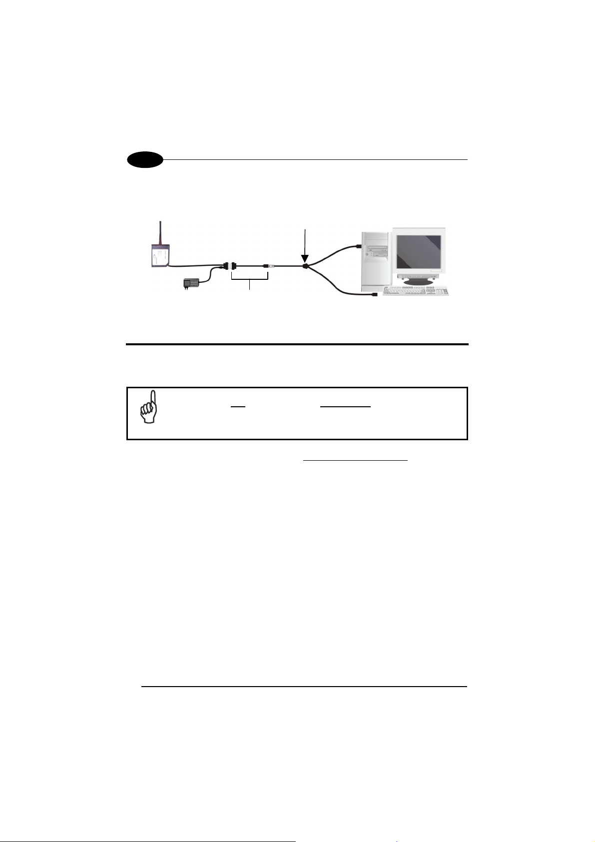
E
STARModem™
Para la conexión del interface de Emulación Teclado, es necesario utilizar el
adaptador según se muestra en la figura inferior:
Cable estándar Datalogic para Emulación Teclado
90ACC1859
Adaptador STARModem™
CONFIGURACIÓN INICIAL DEL STARModem™
Para una correcta configuración del STARModem™ hay que tener en cuenta los
siguientes puntos:
Cuando se use el modem por primera vez, ponga la dirección
deseada del STARModem™ a través del interface serie RS232, ya
NOTA
Para las conexiones del interface para Emulación Teclado/Lápiz
configuracíon unitaria, ponga todos los parámetros a través del interface RS232 ya
sea usando el programa software de DL Sm@rtSet o enviando las cadenas de
configuración al STARModem™. Después, ponga la posición correcta del jumper
hardware según se indica en la tabla del "STARModem™ Setup For Stand Alone
Systems" (ver también la imagen inferior).
Para cambiar cualquier parámetro de configuración en la conexiones del interface
Emulación Tecladol/Lápiz, enviar los comandos de la nueva configuración vía radio
usando terminales RF Datalogic. Otra alternativa, poner el jumper en la posición
RS232 (los parámetros de comunicación RS232 son los valores estándar por
defecto) para enviar las cadenas de configuración al STARModem™ vía el
interface serie y poner el jumper en posición Emulación Teclado/Lápiz para facilitar
esta conexión.
que la dirección estándar por defecto es “Indefinida”.
en modo de
58
Page 65

DATALOGIC
E
Tornillos
Posición 2
Posición 1
Posición 1 = interfaz RS232/Digital
Posición 2 = interfaz Emulación Teclado/Emulación Lápiz
La configuración de los STARModem™ puede efectuarse de tres maneras:
mediante el programa software de configuración de DL Sm@rtSet, enviando las
cadenas de configuración desde el Host vía el interface RS232 o leyendo los
códigos de barras de configuración con el terminal Datalogic RF y enviando los
comandos al STARModem™ vía radio.
DL Sm@rtSet
DL Sm@rtSet está disponible en el CD-ROM del STARModem™ y puede
instalarse en su PC.
DL Sm@rtSet es un programa basado en entorno Windows con un método de
configuración rápido y sencillo vía el interface RS232.
Permite actualizar el software del terminal conectado (ver el Manual de Usuario del
DL Sm@rtSet para mas información).
Cadenas de Configuración
Para realizar la configuracíon inicial del STARModem™, enviar les cadenas de
configuracíon al modem usando cualquier programa de emulación terminal, por
ejemplo Hyper Terminal. La transmisión de las cadenas se realiza usando el
interface RS232.
Asegúrese que el Puerto serie COM de su PC está configurado como
sigue:
9600 baudios, sin paridad, 8 bits de datos, 1 stop bit, protocolo
NOTA
inactivo.
La secuencia de programación es la siguiente:
$+
Comando
$
CR
-
Retorno de carro (0D Hex.)
Fin y grabación de la configuración
Secuencia de caracteres en tabla siguiente
Inicialización de la configuración
59
Page 66

E
STARModem™
Ejemplo
Secuencia comando de programación:
$+ MA0RC1237 $- CR
Caracter tecla retroceso (0D Hex.)
Fin y grabación de la configuración
Dirección STAR-Modem en Stand Alone system:
Inicialización de la configuration
1237
Cada ajuste de los parámetros de configuración elimina la condición activa anterior
para ese parámetro.
Ver el Manual de Referencias del STARModem™ para cambiar los parámetros
que vienen de fábrica.
CONFIGURACIÓN DEL STARMODEM™ EN MODO
DE CONFIGURACIÓN UNITARIA
STARModem™ Receptor (Servidor)
RESTAURAR VALORES DADOS DE FÁBRICA
Cuando sea necesario, enviar la siguiente cadena al STARModem™ via RS232
para restaurar los valores dados de fábrica:
Configuración STARModem™ predefinida
Este comando no restaura la dirección del STARModem™ ni el parámetro Baudio
Radio a sus valores predefinidos.
SELECCIÓN DE LA DIRECCIÓN DE RADIO
La procedura siguiente consiente la selección de la dirección de radio del
STARModem™, de modo que el modem puede recebir datos de dispositivos radio
del sistema.
$+$*CR
60
Page 67

DATALOGIC
E
Inicialización de la Configuración
1.
2.
Ponga la dirección de Radio STARModem™
xxxx = cuatro cifras para dirección STARModem™ (de
0000 a 1999). Esta dirección debe ser única.
3.
Selección del Baudio Radio (no válido para modelos de US)
x = 0 por 9600 baudios
1 por 19200 baudios
Fin y grabación de la Configuración
4.
SELECCIÓN DE LA INTERFAZ
Selección de la cadena de interface deseada para su aplicación, después ponga la
posición correcta del jumper hardware (ver "Configuración del STARModem™“
para programación del jumper).
Por lo que concierne los códigos siguientes, enviar solo la cadena que se adapte a
su aplicación:
Interfaz RS232
Emulación Lápiz
Emulación Teclado
IBM AT o PS/2 PCs
IBM XT
PC Notebook
IBM SURE1
IBM Terminal 3153
IBM Terminals 31xx, 32xx, 34xx, 37xx
Seleccionar el interface para estos terminales IBM, enviar la cadena CLAVE DE
TRANSMISIÓN correcta. Seleccionar el TIPO DE TECLADO si es necesario (por
defecto de fábrica = teclado avanzado).
Make-only keyboard
Make-break keyboard
Advanced keyboard
Typewriter keyboard
$+CP500$-CR
$+CP503$-CR
$+CP505$-CR
$+CP506$-CR
$+CP504$-CR
$+CP0$-CR
$+CP6$-CR
$+CP502$-CR
$+CP501$-CR
$+FK1$-CR
$+FK0$-CR
$+
MA0RCxxxx
MFx
$-CR
Posición
salto
1
2
2
2
2
2
2
2
2
2
2
61
Page 68

E
STARModem™
ALT MODE
La selección de la interfaz siguiente permite una interpretación correcta del PC de
los códigos de barras transmitidos, independientemente de la selección de la
nacionalidad del teclado. No es necesita efectuar la selección de la
nacionalidad del teclado.
(default = Num Lock Unchanged)
Por favor, verifiquen que el teclado numérico este activado en su teclado.
IBM AT- ALT mode
PC Notebook - ALT mode
Wyse Terminal - ANSI Keyboard
Wyse Terminal - PC Keyboard
Wyse Terminal - ASCII Keyboard
Wyse Terminal - VT2200 style Keyboard
APPLE ADB Bus
Digital Terminal VT2xx/3xx/4xx
$+CP507$-CR
$+CP508$-CR
$+CP509$-CR
$+CP510$-CR
$+CP511$-CR
$+CP514$-CR
$+CP513$-CR
$+CP512$-CR
2
2
2
2
2
2
2
1
Para cambiar los parámetros de configuración cuando utilice un
interface de Terminal Digital, envíe los nuevos valores vía radio a
través de terminales RF Datalogic. También puede enviar la cadena
$+CP0$-CR vía radio para ajustar el interface RS232 y definir los
parámetros vía interface serie. Esta operación ajusta los parámetros
del RS232 a los valores estándar por defecto y borra la cabecera
CUIDADO
actual y el terminador. A parte, después de la configuración, debe
restaurar el interface del Terminal Digital, la cabecera y el
terminador, enviando una cadena de comando similar a la que
aparece en el ejemplo siguiente:
$+CP512EA0141EA1102$-CR.
Si ha seleccionado la interfaz emulación teclado, debe también leer entre los
códigos siguientes, el de la nacionalidad de su teclado:
English
Deutsch
Svenskt
Français
Italiano
USA
Español
Belge
$+FJ4$-CR
$+FJ3$-CR
$+FJ5$-CR
$+FJ2$-CR
$+FJ1$-CR
$+FJ0$-CR
$+FJ6$-CR
$+FJ7$-CR
62
Page 69

DATALOGIC
E
STARModem™ Transmisor (Cliente)
RESTAURAR VALORES DADOS DE FÁBRICA
Cuando sea necesario, enviar la siguiente cadena al STARModem™ via RS232
para restaurar los valores dados de fábrica:
Configuración STARModem™ predefinida
Este comando no restaura la dirección del STARModem™, la dirección del
dispositivo de destino Stand-Alone ni el parámetro Baudio Radio a sus valores
predefinidos.
SELECCIÓN DE LA DIRECCIÓN DE RADIO
La procedura siguiente permite la selección de la dirección de radio del
STARModem™, de modo que el modem puede enviar datos a dispositivos de
destino Stand-Alone del sistema.
Inicialización de la Configuración
1.
2.
Ponga la dirección de Radio STARModem™
xxxx = cuatro cifras para dirección STARModem™ (de
0000 a 1999). Esta dirección debe ser única.
3.
Ponga la dirección de Radio del dispositivo de destino
Stand-Alone
xxxx = cuatro cifras para dirección del dispositivo (de
0000 a 1999). Esta dirección debe ser única.
$+$*CR
$+
MA0RCxxxx
MSxxxx
4.
Selección del Baudio Radio (no válido para modelos de US)
x = 0 por 9600 baudios
1 por 19200 baudios
Fin y grabación de la Configuración
5.
No se necesita seleccionar un interface, ya que todas las transmisiones
desde STARModem™ se realizan vía un interface serie.
63
MFx
$-CR
Page 70

E
STARModem™
CONFIGURACIÓN DEL STARMODEM™ EN MODO
DE CONFIGURACIÓN STAR-SYSTEM™
RESTAURAR VALORES DADOS DE FÁBRICA
Cuando sea necesario, enviar la siguiente cadena al STARModem™ via RS232
para restaurar los valores dados de fábrica:
Configuración STARModem™ predefinida
Este comando no restaura la dirección del STARModem™, la dirección de los
dispositivos de destino STAR-System™ ni el parámetro Baudio Radio a sus valores
predefinidos.
SELECCIÓN DE LA DIRECCIÓN DE RADIO
La procedura siguiente consiente la selección de la dirección de radio del
STARModem™, de modo que el modem puede enviar datos a todos los
dispositivos incluidos en la serie de direcciónes definidas para la primera y la última
dirección del dispositivo de destino STAR-System™.
Inicialización de la Configuración
1.
2.
Ponga la dirección Radio del STARModem™
xxxx = cuatro cifras para la dirección STARModem™ (de
0000 a 1999). Esta dirección debe ser única.
$+$*CR
$+
MA1RCxxxx
3.
Ponga la primera dirección del dispositivo de destino
STAR-System™
xxxx = cuatro cifras para la dirección del dispositivo de
destino (de 0000 a 1999).
4.
Ponga la última dirección del dispositivo de destino
STAR-System™
xxxx = cuatro cifras para la dirección del dispositivo de
destino (de 0000 a 1999).
Si se transmite a un solo dispositivo de destino, esta
instalación no es necesaria.
5.
Selección del Baudio Radio (no válido para modelos de US)
x = 0 por 9600 baudios
1 por 19200 baudios
Fin y Grabación de la Configuración
6.
64
MSxxxx
MTxxxx
MFx
$-CR
Page 71

DATALOGIC
Definiendo una serie de direcciónes por los dispositivos de destino,
STARModem™ activa el Roaming en los dispositivos incluidos en esta serie.
No se necesita seleccionar un interface, ya que todas las transmisiones
STAR-System™ se realizan vía un interface serie.
E
STARModem™ - CONFIGURACIÓN PREDEFINIDA
CONFIGURACIÓN INTERFAZ RS232
9600 baudios, sin paridad, 8 bit de datos, 1 bit de stop, protocolo desactivado,
ACK/NACK desde el Host desactivada, retardo intercaracter desactivado, "rx
timeout": 5 seg., FIFO activada, "frame packing" = "frame + [CR]"
CONFIGURACIÓN INTERFAZ EMULACIÓN LÁPIZ
Interpret modo operativo, impulso de conexión 600 µs, conversión al Code 39,
"overflow" medio, nivel de conexión: normal, nivel de descanso: normal, inter-block
plazo desactivado.
CONFIGURACIÓN INTERFAZ EMULACIÓN TECLADO
Teclado americano, "caps lock" inactivo, teclado numérico desctivado, intercaracter e
intercódigos desactivados, emulación control character = Ctrl + Shift + Key.
FORMATO DE DATOS
Código de identificatión desactivado, ninguna cabecera y ningún terminador: RS232
= CR-LF; WEDGE
longitud del código desactivada, dirección "stamping" desactivada, delimitador de
dirección desactivado.
PARAMETROS DE RADIO
Modo de transmisión 1 way, timeout del protocolo de la radio = 2 seg., "single store"
desactivado, ACK/NACK desde el Host remoto desactivada, 19200 baudios radio
(modelos europeos), 36800 baudios radio fijos (modelos de US), "beacon"
desactivado.
= ENTER, "header position" = "first frame field", transmisión de la
65
Page 72

E
STARModem™
GARANTIA
Datalogic garantiza este producto contra todos los defectos de manejo y de
materiales, por un periodo de 24 meses desde la fecha de envio, sabiendo que el
producto funciona y esta en perfectas condiciones.
Datalogic tiene el derecho de reparar o reemplezar el producto sin que eso suponga
una prolongación de la garantía original.
La garantía no será valida si el producto ha sufrido abuso, daños accidentales,
reparaciones no autorizadas o falsificado.
CARACTERISTICAS TECNICAS
Características Eléctricas
Suministro de energía 5 Vdc ±5% De 10 a 30 Vdc
Consumo 2 W
Indicadores Power On (verde)
Características Radio
Frecuencia de funcionamiento 433.92 Mhz 910 Mhz
Transmisión de datos Hasta 19200 baud 36800 baud
Potencia radiada efectiva <10 mW <1 mW
Alcance 50 m 30 m
Modulación RF FSK
Configuración del Sistema
Cantidad máxima de aparatos
por STARModem™
Características ambientes
Temp. De funcionamiento -20° to +50 °C
Temp. De almacenamiento -20° to +70 °C
Humedad 90% sin condensación
Clase de protección IP64
Características Mecánicas
Peso 370 gr
Dimensiones (sin antena) 68 x 84 x 34 mm
Modelos 5 Volt Modelos 10-30 Volt
TX/RX (amarillo)
Status (rojo)
Modelos Europeos Modelos de US
32
66
Page 73
DATALOGIC
E
CONFORMIDAD
Este dispositivo debe ser abierto por una persona cualificada.
STARModem™ es un equipo de Clase III según el Estándar de Seguridad
Eléctrica EN-60950.
Este aparado debe suministrarse cin la unidad de alimentación marcada "Class 2"
con potencia de salida de 5 Vdc ±5% para los modelos 5 Volt, y de 10 - 30 Vdc para
los modelos 10-30 Volt con un cable de < 3m de longitud.
Contacte con la autoridad competente para la gestión de los dispositivos de radio
frecuencia de tu país, para verificar si es necesaria la licencia de uso.
Además se puede encontrar mas información en la página web:
http://europa.eu.int/comm/enterprise/rtte/spectr.htm
67
Page 74

ANTENNA
Position A (standard) Position B
MOUNTING BRACKETS
ST-217 mounting bracket ST-133 mounting bracket
68
Page 75

OVERALL DIMENSIONS
6.7
170.7
84
3.3
68
2.7
4.2
0.16
0.35
9
7.8
0.3
mm
inch
7.6
0.39
1.3
32.7
= 50 =
R
90°
20°
23
0.9
4
0
4
0
.
2
.
1
6
32
1.26
1x45° n° 2
4.2
n°
2
0
.
1
6
n
°
2
46
1.81
42
16.5
73
2.87
2.5
0.09
0.54
13.8
0.68
17.5
30
1.18
2.5
0.09
= 1.96 =
= 40 =
= 1.57 =
26
1.02
25
0.98
7.5
= 35 =
0.29
= 1.37 =
4.5 n. 2
0.17 n. 2
5
.2
2
R
R
2
15
0.59
R
1
3
0.11
.2
5
69
Page 76

STARModem™ CABLE PINOUT
5
1
9
STARModem™ 9-pin female connector
6
Pin RS232 Wedge Pen
1 PC_DATA
2 TX232
3 RX232 KB_DATA KB_DATA
4 + 5 Vdc (Keyboard Supply Voltage) PWR
5 GND GND GND
6 PC_CLK
7 CTS232 KB_CLK
8 RTS232
Power Supply / Alimentazione / Alimentation / Netzteil / Alimentación
Pin Name
5 GND
9 VDC+ (Modem Supply Voltage)
By inserting the power supply connector in the power jack, pin 9 is not
connected.
Inserendo il connettore di alimentazione al jack, il pin 9 non verrà
utilizzato.
En utilsant le jack d'alimentation, le pin 9 ne sera pas utilisé.
NOTE
Bei der Verbindung eines Netzteils mit dem Stromstecker, wird Pin 9
nicht benutzten.
Insertando el conector de la fuente de alimentación en el enchufe, el
pin 9 no está conectado.
70
5 Vdc 400 mA or 10 - 30 Vdc 200 mA
Figure 1 - Power jack polarity
Page 77

/
TYPICAL LAYOUT APPLICATIONS
Modem
DRAGON 1
DRAGON 2
HOST PC
DRAGON 3
F734-E
Stand Alone Mode - STARMODEM™ Server Connected to Host PC
433 MHz
910MHz
RF Connection
DRAGON
5 Volt
Modem
2.4 GHz
Network
DL8700
Stand Alone Mode - STARMODEM™ Server Connected to DL8700
71
Page 78
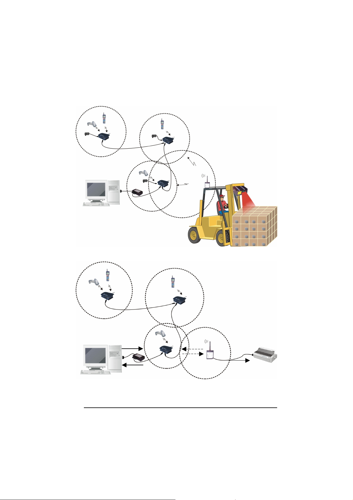
STARGATE 3
HOST
STARGATE 2
STARGATE 1
Modem
SCANNER
STAR-System™ Mode - STARMODEM™ Transmitting Data from Scanner to STAR-System™
STARGATE 3
STARGATE 2
[ENQ]
STARGATE 1
Data
HOST
[ENQ]
Data
Modem
Data
PRINTER
STAR-System™ Mode - STARMODEM™ Receiving Data from STAR-System™ for Printer
72
Page 79

HOST 1
Modem 1
STAR-System™ Mode – Bi-directional Communication
Modem 2
HOST 2
73
Page 80

DATALOGIC S.p.A.,
Via Candini, 2
40012 - Lippo di Calderara
Bologna - Italy
dichiara che
declares that the
déclare que le
bescheinigt, daß das Gerät
declare que el
STAR-Modem™, Radio Modem
e tutti i suoi modelli
and all its models
et tous ses modèles
und seine modelle
y todos sus modelos
sono conformi alla Direttiva del Consiglio Europeo sottoelencata:
are in conformity with the requirements of the European Council Directive listed below:
sont conforme aux spécifications de la Directive de l'Union Européenne ci-dessous:
der nachstehenden angeführten Direktive des Europäischen Rats entsprechen:
cumple con los requisitos de la Directiva del Consejo Europeo, según la lista siguiente:
1999/5/EEC R&TTE
Questa dichiarazione è basata sulla conformità dei prodotti alle norme seguenti:
This declaration is based upon compliance of the products to the following standards:
Cette déclaration repose sur la conformité des produits aux normes suivantes:
Diese Erklärung basiert darauf, daß das Produkt den folgenden Normen entspricht:
Esta declaración se basa en el cumplimiento de los productos con las siguientes normas:
EN 60950, October 1996
: S
AFETY OF INFORMATION TECHNOLOGY EQUIPMENT, INCLUDING ELECTRICAL
BUSINESS EQUIPMENT
ETSI EN 301 489-03, July 2000
ETSI 300 220-3, September 2000
: E
LECTROMAGNETIC COMPATIBILITY AND RADIO SPECTRUM MATTERS
LECTROMAGNETIC COMPA TIBILITY
E
AND SERVICES
(SRD)
: E
LECTROMAGNETIC COMPATIBILITY AND RADIO SPECTRUM MATTERS
HORT-RANGE DEVICES
S
TO
1000 MH
M
W; P
A
RTICLE
; P
ART
OPERATING ON FREQUENCIES BETWEEN 9 KHZ AND
3: S
(SRD); R
Z FREQUENCY RANGE WITH POWER LEVELS RANGING UP TO
ART
3: H
ARMONISED
3.2
OF THE
R & TTE D
(EMC)
PECIFIC CONDITIONS FOR SHORT-RANGE DEVICES
EN
COVERING ESSENTIAL REQUIREMENTS UNDER
IRECTIVE
STANDARD FOR RADIO EQUIPMENT
ADIO EQUIPMENT TO BE USED IN THE
40 GHZ
Lippo di Calderara, 11.10.2002
Ruggero Cacioppo
Quality Assurance Laboratory
Manager
(ERM);
(ERM);
25 MH
500
Z
 Loading...