

Data-Linc Group SRM6200E-SLC User Manual
USER GUIDE
SRM6200E-SLC
Frequency Hopping Spread Spectrum
Ethernet Radio Modem
OMMUNICATIONS
C
ATA
D
NDUSTRIAL
I
It is essential that all instructions contained in the User Guide are followed precisely to ensure proper operation of equipment.
Product User Guide
FCC Notification
This device complies with part 15 of the FCC rules. Operation is subject to the following conditions:
1) This device may not cause harmful interference and
2) This device must accept any interference received, including interference that may
cause undesired operation.
The device must be operated as supplied by Data-Linc Group. Any changes or modifications made to the
device without the express written approval of Data-Linc Group may void the user’s authority to operate the
device.
Caution: This device has a maximum transmitted output power of 955 mW . It is required that the
transmit antenna be kept at least 23 cm away from nearby persons to satisfy FCC RF exposure
requirements.
Note: This equipment has been tested and found to comply with the limits for a Class A digit al device, pursuant
to part 15 of the FCC Rules. These limits are designed to provide reasonable protection against harmful
interference in a industrial installation. This equipment generates, uses and can radiate radio frequency energy
and, if not installed and used in accordance with the instructions, may cause harmful interference to radio
communications. However, there is no guarantee that interference will not occur in a particular inst allation. If
this equipment does cause harmful interference to radio or television reception, which can be determined by
turning the equipment off and on, the user is encouraged to try to correct the interference by one or more of the
following measures:
Reorient or relocate the receiving antenna.
Increase the separation between the equipment and receiver.
Connect the equipment into an outlet on a circuit different from that to which the receiver is connected.
Consult the dealer or an experienced radio/TV technician for help.
Note: Whenever any Data-Linc Group SRM series modem is placed inside an enclosure a label must be
placed on the outside of that enclosure which includes the modem’s FCC ID.
The following antennas are approved for use with Data-Linc Group’s 900 MHz series modems.
NOTE: Per FCC Rules, the maximum power allowed at the antenna is 4 Watts E.I.R.P.
900MHz Directional Antenna
Gain Manufacturer Manufacture Model Number Data-Linc Model Number
8.2 dBi Larsen YA6-900W A-YB
12.2 dBi Larsen YA0006 A-Y10B
900MHz Omni-Directional Antenna
Gain Manufacturer Manufacture Model Number Data-Linc Model Number
5.2 dBi Maxrad MAX-9053 A-OB
7.2 dBi Maxrad BMEFC8985HD A-O5B
0 dBi Ying Hao YH920801/AD-725-A-1 A-06/ADJ
0 dBi Centurion EXC-902-BN A-06BH-3S / 10S (**)
(**) This part number refers to an antenna kit(s). The 0 dBi refers to the antenna portion of the kit.
Note: The antenna used for this device must be professionally installed on a fixed-mounted permanent
outdoor structure for satisfying RF exposure requirements, including antenna co-location requirements
of 1.1307(b)(3).
DATA-LINC GROUP
PN 161-09990-002C

Table of Contents
SRM6200E-SLC User’s Guide
Page
Introduction 3
Quick Start 4
Modem Configuration 6
Main Menu Option (0): Set Operation Mode 8
Main Menu Option (1): Set Baud Rate 10
Main Menu Option (2): Edit Call Book 10
Main Menu Option (3): Edit Radio Transmission Characteristics 12
Main Menu Option (4): Show Radio Statistics 16
Main Menu Option (5): Edit Multi-Point Parameters 18
Main Menu Option (8): Password 21
Modem Location 22
Using an External Antenna 22
Modem Front Panel LED’s 23
Sample Data Communication Links 25
Technical Specifications 27
Troubleshooting 28
Technical Support 29
Return Material Authorization 29
Contact Information 29
○○○○○○○○○○○○○○○○○○○○○○○○○○○○○○○○○○○○○○○○○○○○○○○○○○○○
○○○○○○○○○○○○○○○○○○○○○○○○○○○○○○○○○○○○○○○○○○○○○○○○○○○○
○○○○○○○○○○○○○○○○○○○○○○○○○○○○○○○○○○○○○○○○○○○○○○
○○○○○○○○○○○○○○○○○○○○○○○○○○○○○○○○○
○○○○○○○○○○○○○○○○○○○○○○○○○○○○○○○○○○○○
○○○○○○○○○○○○○○○○○○○○○○○○○○○○○○○○○○○○
○○○○○○○○○○○○○○○○○○○○
○○○○○○○○○○○○○○○○○○○○○○○○○○○○○○○○
○○○○○○○○○○○○○○○○○○○○○○○○○○○○
○○○○○○○○○○○○○○○○○○○○○○○○○○○○○○○○○○○○○○○
○○○○○○○○○○○○○○○○○○○○○○○○○○○○○○○○○○○○○○○○○○○○○○○○○
○○○○○○○○○○○○○○○○○○○○○○○○○○○○○○○○○○○○○○○○○○○
○○○○○○○○○○○○○○○○○○○○○○○○○○○○○○○○○○○○○○○○○○○
○○○○○○○○○○○○○○○○○○○○○○○○○○○○○○○○○○○○○
○○○○○○○○○○○○○○○○○○○○○○○○○○○○○○○○○○○○○○○○○○○○
○○○○○○○○○○○○○○○○○○○○○○○○○○○○○○○○○○○○○○○○○○○○○○○○○
○○○○○○○○○○○○○○○○○○○○○○○○○○○○○○○○○○○○○○○○○○○○○○○○
○○○○○○○○○○○○○○○○○○○○○○○○○○○○○○○○○○○○○○○○○
○○○○○○○○○○○○○○○○○○○○○○○○○○○○○○○○○○○○○○○○○○○○○○○
PN 161-09990-002C
rev 3/29/04
DATA-LINC GROUP
1

SRM6200E-SLC User’s Guide
2
DATA-LINC GROUP
PN 161-09990-002C
rev 3/29/04

SRM6200E-SLC User’s Guide
Introduction
Data-Linc Group’s SRM6200E-SLC has been designed to mount in an Allen-Bradley SLC 500 Slot Rack. The SRM6200ESLC transceiver modem is a high performance, wireless radio modem designed for heavy-duty industrial data
communications in the 902-928 MHz license-free band. It employs advanced spread spectrum frequency hopping and error
detection technology to achieve very reliable, noise and interference immune operation. A high RF data rate of 188kbp s and
superior sensitivity provide ultra reliable data integrity . The SRM6200E-SLC has a rated range of up to 25 miles (40 km) and
an installed range of up to 35 miles (56 km) in optimal conditions with line-of-sight and an omni directional antenna. This can
also be extended further with repeaters or higher gain antenna.
The SRM6200E-SLC can be operated in a number of different modes to satisfy a broad range of communications
requirements. It can be configured for point-to-point or multi-point operation with an unlimited number of remote sites on a
single master depending on data throughput requirements. Repeaters can be used in the system to extend range and
eliminate dead RF zones that are blocked by obstructions.
An external antenna can be used with up to two hundred feet of coax. This provides a boost in signal strength and decreases
induced noise levels. With an external antenna, radio modems can be located inside buildings or metallic enclosures.
Equipped with a 10 Base-T Ethernet port, the SRM6200E-SLC is easily connected via standard 10 Base-T Category 5 patch
cord (provided) to an Allen-Bradley SLC 5/05 CPU ENET port, hub or any other device equipped with a 10 Base-T network
interface.
The User Guide covers the operating modes and configurations that are available to users of the SRM6200E-SLC. It also
provides the user with bench testing instructions, technical information and specifications.
In most applications, the SRM6200E-SLC comes pre-configured for the application in which it is going to be used. In most
cases no other configuration is required. If you are unsure if the modem needs further configuration, please contact Data-Linc
Group.
PN 161-09990-002C
rev 3/29/04
DATA-LINC GROUP
3

SRM6200E-SLC User’s Guide
Quick Start
The SRM6200E-SLC comes pre-configured for your application (unless otherwise requested). In most cases, configuration
settings are not required.
Although each modem is tested before shipment, it is recommended that a bench test be done before the modem is
installed in its application.
In all applications, there is a master modem and one or more remotes. Some applications may also have one or more
repeaters. This “Quick St art” will assume that there is a repeater in the system. If there is not, ignore the p arts that talk
about repeaters, as the remote modems should operate the same with or without repeaters.
The SRM6200E-SLC is available in three different power configurations:
• SRM6200E-SLC is a 12VDC powered device that is designed to take 12VDC in on the barrel jack on the front
panel.
• SRM6200E-SLC/BP is a 24VDC powered device that receives power directly from the backplane and does not
need a separate power supply . Be sure that your 1746 chassis has a large enough supply — Data-Linc Group
recommends the use of the P-4 power supply chassis (a wall transformer power supply has been included for
bench testing purposes).
• SRM6200E-SLC/24V is a 24VDC powered device that is designed to take 24VDC in on the removable screw
terminal connector on the front panel (please note the polarity: positive side marked “+” on the top if you are
supplying your own power).
Locate the modem labeled “Master” and connect its power supply to an appropriate 120V AC power source, then connect it
to the modem. The “P” LED should come on and stay on
Note: on all modems, the “RF Link” LED will come on for the first few seconds after power up.
Next, locate the modem(s) labeled “Repeater” and connect to power. The LED “P” and “RF Link” should come on and stay
on. Now locate the modem(s) labeled “Remote” and connect to power. The LED “P” and “RF Link” should come on and stay
on. The modems are now ready to carry Ethernet data.
Connect the “Master” and “Remote” (or “Repeater/Remote” if your network has one) to the Ethernet equipment that has been
pretested for operation. The device has been designed with a crossover switch. The crossover function interchanges the
transmit and receive pairs removing the need for a crossover cable in certain situations.
The SRM6200E-SLC crossover switch has been factory set in the crossover position. If the system is connected and the
LAN link LED is not lit, the crossover switch (SW3- Diagram 3, pg. 24) may need to be moved to the straight through
position.
4
DATA-LINC GROUP
PN 161-09990-002C
rev 3/29/04

SRM6200E-SLC User’s Guide
T o change the crossover switch remove the SRM6200E-SLC from the Allen-Bradley SLC500 Slot Rack. Under the edge of
the enclosure is a black and silver slide switch (S3- Diagram 3, page 24). If connecting to an Ethernet hub, the crossover
switch should be set in the straight through (left) position. If connecting to a PC, PLC or most other Ethernet interface
equipped devices, the crossover switch should be set in the crossover (right) position.
Note: The SRM6200E-SLC will not support “Peer to Peer” communications. The equipment that is attached to the
SRM6200E-SLC must be capable of operating in a “Master (host) to Remote” network
.
It is recommended that a “Ping” test be done at this point. This can be done in either direction, but remember that only a
“Master to Remote” or “Remote to Master” connection can be established through the modems. Also note that because of
the MAC filtering done by the modems, if you take a piece of Ethernet equipment on one side of the SRM6200E-SLC
network and move it to the other side of said network, you must power down both the “Master” and the effected “Remote” in
order to re-establish connectivity through the modems. If powering down the modem is not practical to the applications, the
modems will rebuild the MAC filter table in approximately six minutes and communications should return. Once a successful
“Ping” test has been done, the modems are ready for communication. If the “Ping” test was not successful, please refer to
the trouble shooting section of this manual or contact Data-Linc Group tech support for assistance.
PN 161-09990-002C
rev 3/29/04
DATA-LINC GROUP
5

SRM6200E-SLC User’s Guide
Configuration
In most cases, the SRM6200E-SLC comes pre-configured from the factory . However, it may sometimes be necessary to
change the configuration. Most parameters are changed in the radio section of the modem although there are a few settings
that are set using switches. If you are not sure if you need to change the configuration of the SRM6200E-SLC, you probably
don’t. Please contact Data-Linc Group for further information if you are unsure about your configuration.
Switch Settings
T o access the switches, remove the modem from the SLC Rack. The switch bank (SW1-Diagram 3, pg. 24) is located in the
center of the large PCB.
Note: Leave switch positions 4, 5 and 6 at factory setting of off unless otherwise directed by Data-Linc Group.
Changing these switches requires a radio parameters change.
MAC Filtering Function
All devices capable of generating Ethernet traffic have a MAC (Medium Access Control) address. This address is used in the
communications of Ethernet data.
The SRM6200E-SLC is factory set to perform MAC level filtering. This means that it learns all the MAC addresses from the
LAN it is connected to, and only forwards data packets across the radio links which are destined for addresses located
across the radio link. The MAC filtering function is enabled by setting switch (SW2-Diagram 3, pg.24) to the on position.
The MAC address table can store up to 10,000 addresses. Each entry to the table has a lifetime of six minutes after which
the address is deleted. This dynamic table building allows for the possibility of stations being removed from the LAN. The net
result of this filtering functionality is the reduction of unnecessary network traffic across the radio link.
Note: Many Ethernet networks have data packets that are not covered by the MAC filter function (broadcast packets
for example). These packets can occupy tremendous amount of the network’s bandwidth and overwhelm the
SRM6200E-SLC section of the network. If the SRM6200E-SLC’s are going to be installed where they are linked to
an open network (on office network, etc.), a properly configured router or switch should be installed to protect the
modems from excessive data traffic. If you are unsure about your network, please consult with your network
administrator.
6
DATA-LINC GROUP
PN 161-09990-002C
rev 3/29/04
SRM6200E-SLC User’s Guide
Radio Parameter Configuration
The SRM6200E-SLC allows you to set several parameters to suit your particular application. All adjustments are done
through the SRM6200E-SLC setup program, a user interface that eliminates the need for setup diskettes or custom software.
T o access the configuration menu, connect the radio modem’s configuration port to any terminal program with port settings of
19.2Kbaud, 8 data bits, no parity and one stop bit. With the modem connected to the PC running the terminal program,
press the Configure button. While any terminal program will work, examples for this manual were generated using the
Microsoft Windows 2000 application “HyperT erminal.”
Note: When using HyperT erminal, set Handshaking to none and use a standard straight through cable. If you are
using something other than HyperTerminal, it may be necessary to use a cable that has pins 4 and 6 connected
together on the modem side of the cable. Contact Data-Linc for further information.
Table 1: Terminal Settings
retemaraP gnitteS
etaRduaB00291
stiBataD8
ytiraPenoN
stiBpotS1
lortnoCwolFenoN
When the setup program is invoked the RF “IN” LED on the SRM6200E-SLC front panel will flash once when the Configure
button is pressed and the RF “Link” LED will remain on for the entire time the radio modem is in setup mode.
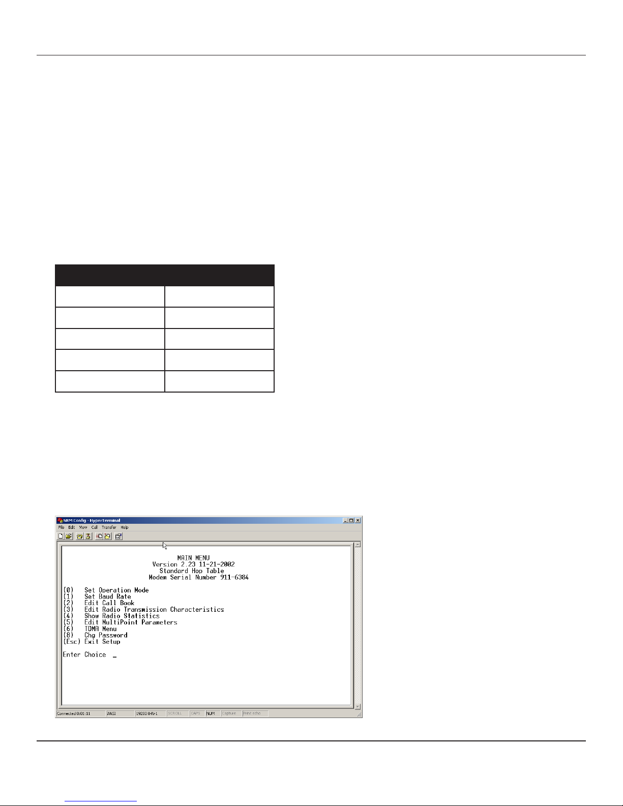
The main menu provides the radio modem’s unique call book number and the set of choices for editing the operational
parameters and viewing the performance data.
Figure 1: Main Menu
PN 161-09990-002C
rev 3/29/04
DATA-LINC GROUP
7
SRM6200E-SLC User’s Guide
Main Menu Option (0): Set Operation Mode
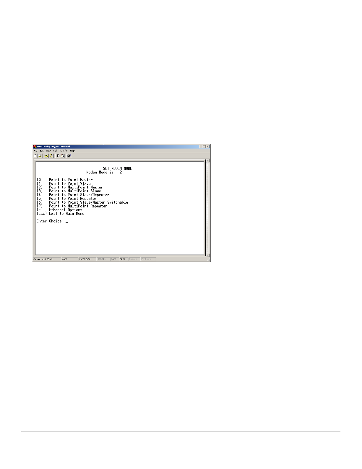
When item (0) is selected, the Operation Mode Menu appears as shown in figure 2. The Operation Mode option is used to
designate the method in which the particular SRM6200E-SLC will be used. The SRM6200E-SLC operates in a master to
remote configuration; therefore, any radio modems that are intended to operate together must be set up as such. In a pointto-point setup, either the Master or Remote may be used on either end of the communications link. One consideration when
setting up the radio modems is that a number of parameters are controlled by the settings in the Master; therefore, you may
wish to deploy the Master on the communications end where you will have easier access to the radio modem.
Figure 2: Mode Menu
Shown below are example settings. Please refer to supplied configuration sheets for your modem’s configuration.
(0) Point-to-point Master
The SRM6200E-SLC operates in a master/remote configuration. When designated as a master in point-to-point mode,
the radio modem will call any or all remotes it is instructed to call in the call book. The Master determines the settings
used for all Radio Transmission Characteristics (except power), regardless of the settings in the remotes and/or
repeaters.
(1) Point-to-Point Remote
When set up as a point-to-point remote, an SRM6200E-SLC will communicate with any master in its call book, either
directly or through one or two repeaters. When functioning as a remote, the Entry to Call feature in the radio modem’s
call book (Figure 3) is not operational. The remote will communicate with any master on the list that calls.
(2) Point-to-Multi-Point Master
The SRM6200E-SLC may be set to run in multi-point mode, which allows one master to simultaneously be in
communication with numerous remotes. A point-to-multi-point master will communicate only with other radio modems
designated as point-to-multi-point remotes or point-to-multi-point repeaters.
(3 ) Point-to-Multi-Point Remote
Setting (3) allows the radio modem to operate as a remote in a multi-point network.
Please refer to the section entitled multi-point operation, for more information on running a multi-point network.
8
DATA-LINC GROUP
PN 161-09990-002C
rev 3/29/04
 Loading...