

Page 1
USER GUIDE
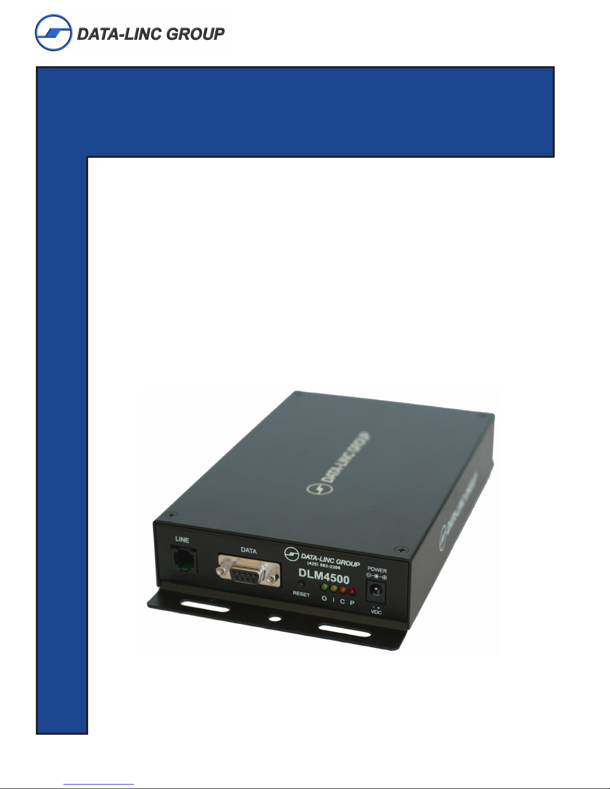
DLM4500
Dial-Up/Leased Line Modem
OMMUNICATIONS
C
ATA
D
NDUSTRIAL
I
It is essential that all instructions contained in the User Guide are followed precisely to ensure proper operation of equipment.
Page 2

DLM4500 User Guide
Patents
This device covered by one or more of the following patents: 6,031,867; 6,012,113; 6,009,082; 5,905,794;
5,864,560; 5,815,567; 5,815,503; 5,812,534; 5,809,068; 5,790,532; 5,764,628; 5,764,627; 5,754,589;
D394,250; 5,724,356; 5,673,268; 5,673,257; 5,644,594; 5,628,030; 5,619,508; 5,617,423; 5,600,649;
5,592,586; 5,577,041; 5,574,725; D374,222; 5,559,793; 5,546,448; 5,546,395; 5,535,204; 5,500,859;
5,471,470; 5,463,616; 5,453,986; 5,452,289; 5,450,425; D361,764; D355,658; D355,653; D353,598;
D353,144; 5,355,365; 5,309,562; 5,301,274 Other Patents Pending.
DATA-LINC GROUP
PN 161-10008-001A
Rev 4/04
Page 3

Table of Contents
DLM4500 User Guide
Page
Introduction 3
Connection Points and LED Descriptions 4
Equipment Connections and Interface Descriptions 5
Quick Start 7
Quick Configuration 10
Technical Specifications 12
Technical Support 14
Return Material Authorization 14
Contact Information 14
○○○○○○○○○○○○○○○○○○○○○○○○○○○○○○○○○○○○○○○○○○○○○○○○○○○
○○○○○○○○○○○○○○○○○○○○○○○○○○○○○○○○○
○○○○○○○○○○○○○○○○○○○○○○○○○○○
○○○○○○○○○○○○○○○○○○○○○○○○○○○○○○○○○○○○○○○○○○○○○○○○○○○
○○○○○○○○○○○○○○○○○○○○○○○○○○○○○○○○○○○○○○○○○○○○○○
○○○○○○○○○○○○○○○○○○○○○○○○○○○○○○○○○○○○○○○○○○○○
○○○○○○○○○○○○○○○○○○○○○○○○○○○○○○○○○○○○○○○○○○○○○○○
○○○○○○○○○○○○○○○○○○○○○○○○○○○○○○○○○○○○○○○○○
○○○○○○○○○○○○○○○○○○○○○○○○○○○○○○○○○○○○○○○○○○○○○○
Appendix A
Enclosure Dimensions 15
○○○○○○○○○○○○○○○○○○○○○○○○○○○○○○○○○○○○○○○○○○○○
Appendix B
Complete AT Commands 16
Complete S-Registers 27
○○○○○○○○○○○○○○○○○○○○○○○○○○○○○○○○○○○○○○○○○○○
○○○○○○○○○○○○○○○○○○○○○○○○○○○○○○○○○○○○○○○○○○○○○
PN 161-10008-001A
rev 4/04
DATA-LINC GROUP
1
Page 4

DLM4500 User Guide
This Page is Intentionally Left Blank
2
DATA-LINC GROUP
PN 161-10008-001A
rev 4/04
Page 5
DLM4500 User Guide
Introduction
The Data-Linc Group DLM4500 modem is designed to work on public dial-up telephone systems. The modem will work on
both dial-up voice grade phone lines and leased lines. It connects to a normal telephone service using a RJ-1 1 jack (2 wire)
and connects to the users equipment via a 9-pin DB-9 connector utilizing RS232 signals and screw terminals if a AE-485
(2-wire) or AE-422 (4-wire) unit.
The Data-Linc Group DLM4500 is a compact modem designed and manufactured to operate in industrial applications. It
has a wide DC voltage input power range and the operating temperature range of this device is -40° to +70° C.
The mechanical and electrical specifications are listed in Appendix B.
The DLM4500 has front panel LED indicators for Power (Red), Data In from user equipment (Y ellow), Data Out to users
equipment (Green), and Carrier Detect (Amber).
The DLM4500 is configured using ‘A T’ style commands sent via the 9-pin port while the modem is in ‘Command Mode’.
Factory default is set at 9600 baud. All normal configurations are performed using the RS232 connection on the front panel
even if the units are a AE-485 or AE-422 model.
A complete list of ‘AT’ commands are in appendix A. Note that all AT command character strings must end with a carriage
return character (Enter key , ctrl M, 0xd hex).
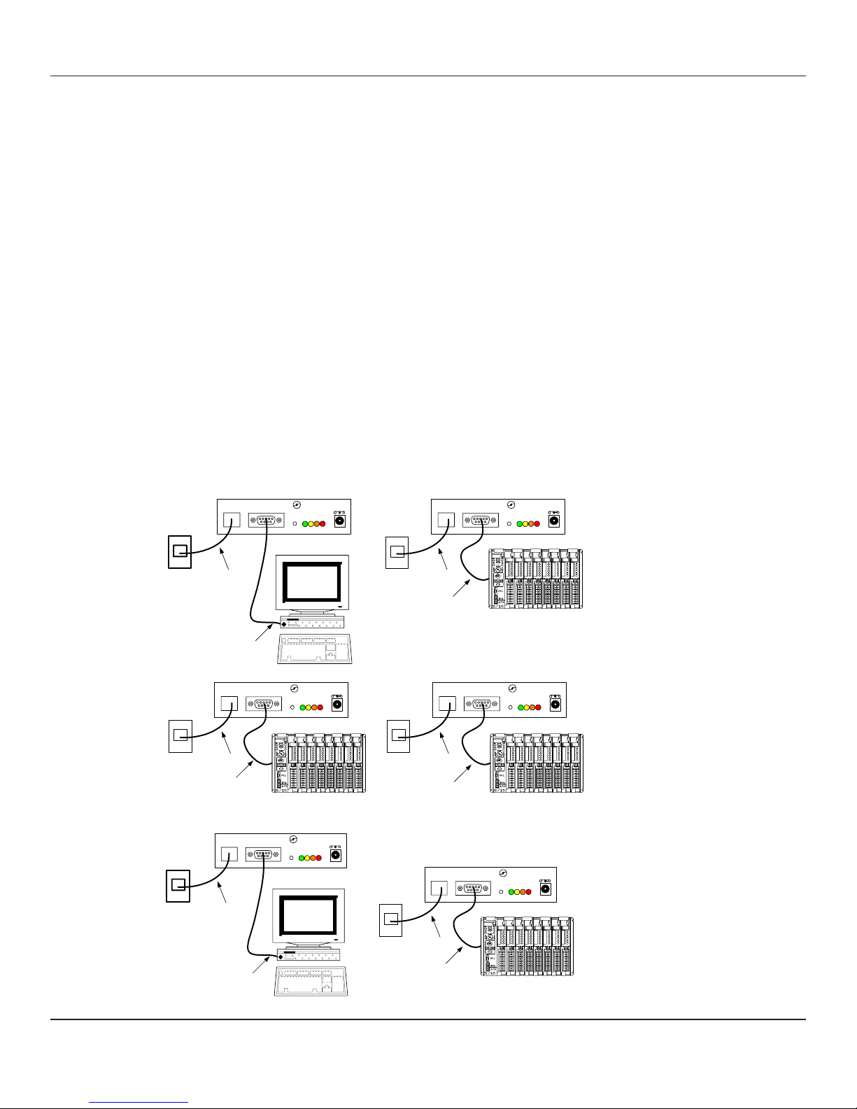
Systems Examples
Diagram 1
Dial-Up
Diagram 2
Leased Line
Dial- Up Connec tion
to Te lco Netw ork
RS-232
LINE
Dial- Up Connec tion
to Te lco Netw ork
RS-232
LINE
Telco or Privat e
Lease d Line
DATA-LINC GROUP
(425) 882-2206
DATA
LINE
DLM4 500
RESET
POWER
- +
C PO
I
VDC
LINE
Master
Dial- Up Connec tion
to Te lco Netw ork
DATA-LINC GROUP
(425) 882-2206
DATA
DLM4 500
+
RESET
POWER
- +
C PO
I
VDC
Remote 0
RS-232
DATA-LINC GROUP
(425) 882-2206
DATA
DLM4 500
+
RESET
POWER
- +
C PO
I
VDC
Dial- Up Connec tion
to Te lco Netw ork
LINE
DATA-LINC GROUP
(425) 882-2206
DATA
DLM4 500
+
RESET
POWER
- +
C PO
I
VDC
Remote 1Remote 2
RS-232
DATA-LINC GROUP
(425) 882-2206
DLM4 500
C PO
I
Master
POWER
- +
VDC
LINE
DATA-LINC GROUP
(425) 882-2206
DLM4 500
C PO
I
POWER
- +
VDC
DATA
+
RESET
DATA
RESET
Remote
RS-232
PN 161-10008-001A
rev 4/04
Telco or Privat e
Lease d Line
RS-232
DATA-LINC GROUP
3
Page 6
DLM4500 User Guide
Connection Points and LED Descriptions
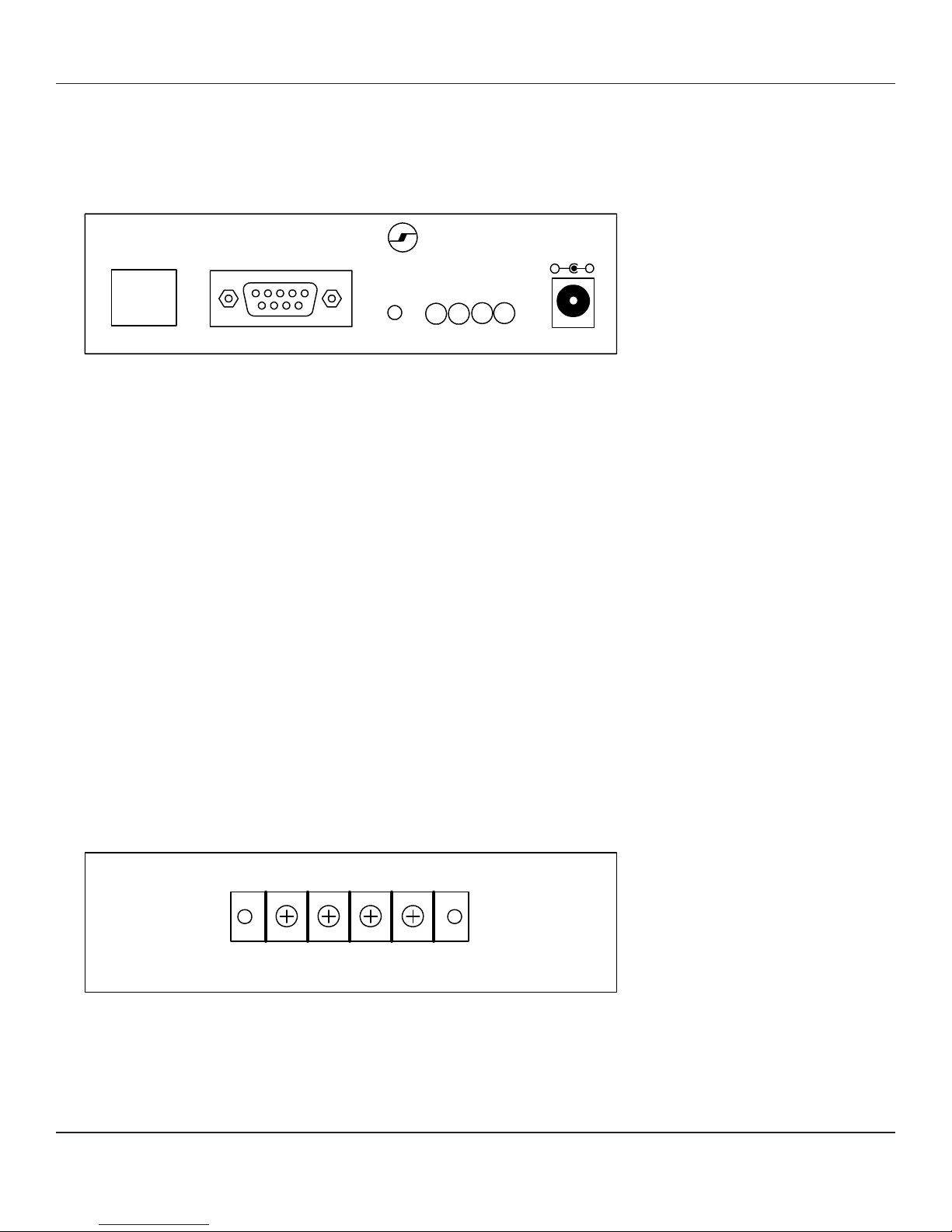
Figure 1
Front Panel Connections – (Left to Right)
DATA-LINC GROUP
LINE
DATA
(425 ) 88 2-220 6
DLM4500
POWER
-
+
RESET
O
I
P
C
RJ-1 1 — Phone Line
DB-9 — Data Port RS232
pin 1 CD Out (Carrier Detect)
pin 2 Data Out
pin 3 Data In
pin 4 DTR In (Data terminal ready)
pin 5 Signal Ground
pin 6 DSR Out (Data set ready)
pin 7 RTS In (Request to send)
pin 8 CTS (Clear to send)
pin 9 N/C
Push-Button Switch — Modem Reset
Led Array
O - Green (data out/line in)
I - Yellow (data in/line out)
C - Amber (line carrier detect)
P - Red (DC power)
2-Position Terminal Block — DC Power In (note the polarity + and –)
- +
VDC
Figure 2
Rear Panel Connections – AE-485 and AE-422 (when option is installed)
12 34
(AE-485) - +
(AE-422) DO - DO + DI - DI +
AE-485 AE-422
1 N.C. 1 DO - (Data Out -)
2 I/O - (Data in/out -) 2 DO + (Data Out +)
3 I/O + (Data in/out +) 3 DI - (Data In -)
4 N.C. 4 DI + (Data In +)
4
DATA-LINC GROUP
PN 161-10008-001A
rev 4/04
Page 7

DLM4500 User Guide
Equipment Connections
The DLM4500 can be purchased with three types of serial interfaces. RS232 only (standard), AE-422 4-wire (optional), or
AE-485 2-wire (optional). All unit s have the RS232 connector on the front. This is always used to configure the modem. The
AE-422 and AE-485 connections are on the rear of the unit. The units can have the RS232 connected at the same time as
the AE-485 or AE-422, but you can not send data into both the front and rear connections at the same time or data
collisions will occur.
RS232
The front RS232 connection is built as a DCE configuration.
For a RS232 connection, use a cable that matches the user equipment. If the users equipment is also a DCE device a null
modem cable must be used. If it is a DTE device then a straight through cable will work.
AE-422
The AE-422 connections consist of a wire p air for data out, and a wire pair for dat a in. Both pairs have a plus (+) and a
minus (-) polarity . To make a AE-422 connection, wire the DLM4500 Data In pair to the Data out from connecting
equipment. Verify that the Data-In LED on the front p anel is not on. If it is on all the time turn the wire pair over (reversed
polarity). Data Linc Group AE-422 usually connect s the ‘+’ to an A cont act and connect s the ‘–‘ wire to a B contact.
Now send some data characters out of the connected equipment. The Data-In LED should flash. If it does not, check that
the Data OUT from your equipment is connected to the Data-IN on the rear of the DLM4500.
If the DLM4500 In LED flashes then connect the DLM4500 Data-Out wire pair to the connecting equipment. Note the
polarity of the connection made to the Data-In lines above. Use the same polarity on the Data-Out connection. V erify the
plus and minus polarity .
If no LED’s blink, then some things can be wrong are: (Note: At high baud rates the blinking may be very fast and faint.)
a. The modem is not connected to the equipment. -Check the cables.
b. DC power is missing or wired backwards-Check the power supply .
c. The equipment you are using is set for the wrong communications port. Match the programs port settings to the
computers physical port number that the cable is plugged into.
d. The equipments program is not running.
e. The AE-422 wire p airs are not cross-connected TX-to-RX and RX-to-TX, or either wire pair in inverted (+and –
lines are swapped backwards). Note that there are 7 ways to miss connect the 2 pairs, and only one way to
connect them correctly.
f. The communications port is not an RS-422 device, or if using an RS-422 converter the converter is broken or
needs power.
PN 161-10008-001A
rev 4/04
DATA-LINC GROUP
5
Page 8

DLM4500 User Guide
AE-485
The AE-485 connection is made with one wire p air . This pair has a plus (+) and a minus (-) polarity. Af ter connecting the
wire pair, send some dat a out of the connected equipment. The Data-In LED on the front panel should flash. If it does not,
invert the wire pair and try again. Data-Linc Group AE-485 usually connects the ‘+’ to an A cont act and connects the ‘–‘ wire
to a B contact.
If no LED’s blink, then some things that could be wrong. (Note: at high baud rates the blinking may be very fast or faint.)
a. The modem is not connected to the equipment. -Check the cables.
b. DC power is missing or wired backwards -Check power supply .
c. The equipment you are using is set for the wrong communications port. Match the programs port settings to the
computers physical port number that the cable is plugged into.
d. The equipments program is not running.
e. The AE-485 wire pair is inverted (+and – lines are swapped backwards).
f. The communications port is not an RS-485 device, or if using an RS-485 converter the converter is broken or
needs power.
6
DATA-LINC GROUP
PN 161-10008-001A
rev 4/04
Page 9
DLM4500 User Guide
Dial Up Quick Start and Testing
The following setup procedure is for a DLM4500 in Dial-Up mode. It assumes that two phone jacks of dial-up lines are
available
1. Unpack the modem(s).
2. Verify that you have all of the p arts and cables to power and connect the modem to your equipment. You must be using
a PC with an RS232 serial communication port. All three versions of the DLM4500 can be configured via the RS232 port.
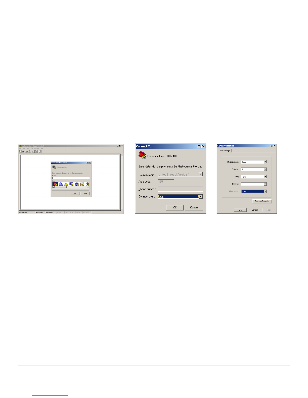
3. Start a terminal program from the PC. Use a program like Hyperterminal or Procomm. Set the communications settings
in the terminal program. You must set or verify the setting for at least the following parameters:
Serial Communications Port Mumber
Speed: Baud Rate
Character ormat: Parity , Number of Data bits, Number of S top bit s (n,8,1)
Handshake / Flow Control: None
Figure 3 Figure 4 Figure 5
4. Apply DC power to the DLM4500. Check the Power LED. It must be ON. If not check:
a. DC power is off or disconnected. Check for the presence of a nominal 12 volts DC on the power connector .
b. DC power is wired backwards. Check the source voltage with a voltmeter .
5. Reset the modem by pressing the Reset button on the front of the unit. This resets the modem and returns the AT
command set to “last stored values” in NVRAM. The modem is ready to accept setup commands.
6. Connect the computer to the DLM4500 with a straight through 9 pin cable. DO NOT CONNECT THE PHONE LINE YET.
Check that only the RED Power LED is On.
7. T ype the command string ‘AT’, then the Enter Key. The modem must reply with the characters ‘OK’. If this does not
happen, recheck step 6 above.
8. The DLM4500 will be configured to your application if the information was supplied to Data-Linc Group during the order
process. If not the Baud Rate and other paramater should be checked before connecting the modems (See Quick
Configuration for help)
9. Get the phone number of the modem you want to connect with. Connect a standard phone to the phone line. Pick up the
phone handset and verify that you get a dial tone. then remove the phone line from the phone and plug it into the
DLM4500.
10. T ype the command string “ATDTxxx xxx xxxx” then the Enter Key . This is the standard dial string. (where the x’ s(x) are
replaced with the 7 or 10 digit phone number)
PN 161-10008-001A
rev 4/04
DATA-LINC GROUP
7
Page 10

DLM4500 User Guide
1 1. The modem will now take the phone line Of f- hook and dial when the dial tone is received. The speaker will make
several noises including the dial tone. If a connection is made the modems speaker will go off, the Amber (carrier) LED
will illuminate and ‘Connect xxxx’ will display, where xxxx is the baud rate, and after that will display the error
correction modes if any is used.. If using a terminal program the modem will automatically be set in data transfer mode.
Failure to make a connection can be the result of:
a. Wrong phone number. Use a regular phone to dial the number and listen to the response.
b. No matching modem at the other end of the phone line.
c. Other modem must be set to answer the phone.
d. Other modem must be turned on.
e. Other modem must be plugged in.
f. This modem must be commanded to dial.
g. Connected software must support a modem and must dial out.
h. Modems at each end must have matching or compatible settings
12. Data can now be sent in either direction.or if a jumper is placed in the DB-9 Connector between pins 2 and 3 any
data sent from the master to the remote will be looped back. In this "Loopback" test the I and O LED’s should be
blinking when data is being sent back to the originating PC.
13. Disconnect the call. To set the modem into command mode while in data mode, send the escape sequence characters
[pause] +++ [p ause] then wait for “OK”. Then type ATH(enter) to hang up an existing call. Unit will respond with “OK”.
End Dial-Up Quick Start and Testing
Leased Line Quick Start and Testing
The following setup procedure is for a DLM4500 in Leased Line mode. It assumes that two phone jacks of leased line or
phone cord wire is available for testing.
1. Unpack the modem(s).
2. Verify that you have all of the p arts and cables to power and connect the modem to your equipment. You must be using
a PC with an RS232 serial communication port. All three versions of the DLM4500 can be configured via the RS232 port.
3. St art a terminal program from the PC. (Note: See Dial-Up Quick St art and Testing of setup help)
4. Apply DC power to the DLM4500. Check the Power LED. It must be ON. If not check:
a. DC power is off or disconnected. Check for the presence of a nominal 12 volts DC on the power connector .
b. DC power is wired backwards. Check the source voltage with a voltmeter .
5. Reset the modem by pressing the Reset button on the front of the unit. This resets the modem and returns the AT
command set to “last stored values” in NVRAM. The modem is ready to accept setup commands.
6. Connect the computer to the DLM4500 with a straight through 9 pin cable. DO NOT CONNECT THE PHONE LINE YET.
Check that only the RED Power LED is On.
7. Press reset button, wait one second ( in leased line mode the modems will only accept AT commands for the first 10
seconds, and after 30 seconds should have started their connection process) then type the command string ‘AT’, then
the Enter Key . The modem must reply with the characters ‘OK’. If this does not happen, recheck step 6 above and try
again.
8
DATA-LINC GROUP
PN 161-10008-001A
rev 4/04
Page 11

DLM4500 User Guide
8. The DLM4500 will be configured to your application if the information was supplied to Data-Linc Group during the order
process. if not the Modem Mode (ie Master or Remote), Baud Rate and other paramater should be checked before
connecting the modems (See Quick Configuration for help)
9. Connect a Master configured DLM4500 to a Remote configured DLM4500 using a phone RJ-1 1 cord. The modems will
automatically connect after approximately 30 seconds. The carrier LED on both modems should light.
10. Leaving the PC computer connected to either of the modems, connect a wire jumper (bent paper clip) between pins 2
and 3 of the other (non-PC connected) DLM4500.
1 1. T ype characters on the PC keyboard while running the terminal program. The characters must echo back on the display
exactly as typed.
12. Remove the 2-3 pins jumper, and the phone cord connection. Connect the DLM4500 to the leased line. Connect the
second modem to the RJ-1 1 at the other location. The modems will make a connection after approximately 30 seconds.
If the connection is dropped the units will automatically reset and try to restore the connection.
End Leased Line Quick Start and Testing
PN 161-10008-001A
rev 4/04
DATA-LINC GROUP
9
Page 12

DLM4500 User Guide
Quick Configuration ***For Most Applications the DLM4500 Comes Preconfigured
Note: The Enter key produces the ASCII character ‘cr’ carriage return (decimal 13, hex 0d).
Note also that there are no ‘O’s (ohs) in any of the following A T command string. All round
characters are the number zero (0).
T o verify the settings before and after changing p arameters type the command string:
A T&V (Enter) then examine the settings and registers displayed on the screen.
A. Set to Chipset’s default
A T&F0 (Enter)
Responds OK
B. Set Connection and Correction Modes
A T&D0&K0#P0%C0\K3\N4%E0$LB=3&W0 (Enter)
Responds OK
C. Baud Rate
If this modem is to be forced to connect and communicate at a fixed baud rate, the following command will need to be
entered. If an auto-connect baud rate sequence is used between modems then skip this section and go to step D.
Note: The most industrial equipment are operated at pre-selected fixed baud rates. These A T commands are
used to force the modem to connect at only the specified baud rate. It will not hunt to find a matching baud rate.
A T$SB9600$MB9600&W0 (Enter) - Where 9600 in both places is the desired baud rate
Responds OK
D. Mode
Dial-Up
T ype:AT&L0%DC0&W0 (Enter)
Responds OK
Leased Line mode enter:
Master
T ype: AT&L1%DC1&W0 (Enter)
Responds OK
Remote
T ype: AT&L2%DC1&W0 (Enter)
Responds OK
Note: Leased line operations require one modem to be a Master and other to be a Remote.
10
DATA-LINC GROUP
PN 161-10008-001A
rev 4/04
Page 13

Short Description of AT Commands Used in Quick Configure Sections
0F&stluafeds'tespihcotmedomteseR
0D&RTDserongI
0K&lortnoCwolFselbasiD
0P#ytiraPoN
0C%noisserpmoCselbasiD
1CD%)yaleddnoces01(edomtuokcolTAselbanE
3K\yletaidemmidnesotlortnoCkaerBsteS
4N\edoMtcerroCrorrE-noN
0L&edoMpU-laiDteS
1L&retsaMeniLdesaeL
2L&etomeReniLdesaeL
0E%sdnammoCBM$dnaBS$ehtybteSetaRduaBskcoL
DLM4500 User Guide
3=BL$sm03otkaerBfohtgneLehtsteS
00291BS$00291otetaRduaBsteS
00291BM$00291otdeepStroPsteS
0W&yromeMgnikroWnisgnitteSserotS
Reconfiguring a DLM4500 after setting it to Leased Line mode
Since there is no jumper or switch to change between Leased Line and Dial-Up/Command Mode on the DLM4500, a
special AT command is used during a 10 second time window after powering up or pressing the reset switch to allow
changing modem settings.
T o get a Leased Line configured DLM4500 modem into Command Mode follow these step s:
-Remove power from DLM4500
-Connect PC to RS232 9-pin port. St art a Terminal program
-Apply Power to DLM4500
-Press Reset on front panel
-Wait 1 or 2 seconds
-Type the following S tring AT%DC0&L0<enter>
-Then follow the Quick Configuration Guide.
The DLM4500 has many commands and various operating modes. It can be configured to perform under almost all type of
system designs. This manual does not try to cover each and every possible combination. If you are trying to use the
DLM4500 in a particular mode and you can not decide what commands to use from Appendix A, then please contact
Data-Linc Group Technical services for assistance. (Contact infromation is on page 14.)
PN 161-10008-001A
rev 4/04
DATA-LINC GROUP
11
Page 14

DLM4500 User Guide
Technical Specifications
ecafretnI232SRECDelameF9-BD
setaRataDtroPlaireS
)lanoitpO(ecafretnI584-EAcn/+/-/cn-pirtSreirraBnoitisoP4
)lanoitpO(ecafretnI224-EA
egnaR224dna584-EA daoLdnaeziSeriWnosdnepeD-mumixam.tf0001
etaRataD224dna584-EAspb002,511otpU
tamroFataD .stib11ro01suonorhcnysa,yranib,laireS
srotacidnIDEL )neerg(TUOataDdna,)wolleY(NIataD,)rebmA(tceteDreirraC,)deR(rewoP
rotacidnIoiduA gnirotinoMnoitcennoCroftliucriCoiduAdeddebmE
egatloVtupnIelbaliavAegnaRrediW-CDV81-9
noitpmusnoCrewoPsttaw0.3xaM
ecafretnIenohpeleT11-JR
tceteDegatloVgniRSMR051ot83
detceteDycneuqerFgniRzH86ot3.51
,002,511,006,75,004,83,002,91,006,9,008,4,004,2,002,1,003
spb004,032dna
+ID/-ID/+OD/-OD-pirtSreirraBnoitisoP4
krowten224-SRnommocano224-EA/0054MLD6fomumixaM
leveLtimsnarTataD)sgniteesyrtnuocybseirav(mBd11-
egnaRcimanyDCGABd34
egnaRerutarepmeTgnitarepO04-
ytidimuHytidimuhgnisnednoc-non%59xaM
ytilibatSycneuqerF+%10.0
ytivitisneSrevieceRsnoitidnocesac-tsrowrednumBd34-
ecnelaviuqEregniRB3.0
noitalosIAADCAV0051
reffuBdnammoCsretcarahC06
noisserpmoCataD )tuphguorht1:2(5PNM,)tuphguorht1:4(sib24.V
noitcerroCrorrE)4-3PNMroM-PAL(24.V
0
0
851ot
0
04-(F
0
07ot
)C
12
DATA-LINC GROUP
PN 161-10008-001A
rev 4/04
Page 15

Technical Specifications Cont.
sedoM
DLM4500 User Guide
A121lleB;22.V,siv22.V,23.V,sib23.V,43.V,43.V,decnahne43.V
311/301dna
setaRataDtneilC-ot-tneilC
thgieW)gk67.(.bl86.1
noisnemiDerusolcnE segnalfgnitnuomrevo)mc49.3x54.21x68.22("45.1x"9.4x"0.9
lairetaMerusolcnEleetseguag81
noitartsigeRCCFE-5M-41852-ASU-7UAgeRCCF
,008,61,002,91,006,12,000,42,004,62,008,82,002,13,006,33
spb003-0,002,1,004,2,008,4,002,7,006,9,000,21,004,41
PN 161-10008-001A
rev 4/04
DATA-LINC GROUP
13
Page 16

DLM4500 User Guide
Technical Support
Data-Linc Group maintains a fully trained staff of service personnel who are capable of providing complete product
assistance. They can provide you with technical, application, troubleshooting, and warranty assistance. Our technical staff is
based in Bellevue, Washington USA and may be reached at (425) 882-2206 or e-mail
support@data-linc.com
Product Warranty
Data-Linc Group warrants equipment of its own manufacture to be free from defects in material and workmanship for one year
from date of shipment to original user. Dat a-Linc Group will replace or repair , at our option, any part found to be defective.
Buyer must return any part claimed defective to Data-Linc Group, transportation prepaid.
Return Material Authorization
If a part needs to be sent to the factory for repair , contact Data-Linc Group’ s corporate office and request a Return Material
Authorization (RMA) number. The RMA number identifies the part and the owner and must be included with the p art when
shipped to the factory .
Contact Information
Corporate Office Data-Linc Group
3535 Factoria Blvd. SE
Suite 100
Bellevue, Washington 98006 USA
T elephone: (425) 882-2206
Fax: (425) 867-0865
E-mail: info@data-linc.com
Web site: www .data-linc.com
14
DATA-LINC GROUP
PN 161-10008-001A
rev 4/04
Page 17

Appendix A
Enclosure Dimensions
DLM4500 User Guide
7.75 in
19.69 cm
4.90 in
12.45 cm
1.54 in
3.94 cm
1.08 in
2.74 cm
4 Places
0.35 in
.89 cm
4 Places
2.45 in
6.22 cm
Reference
9.00 in
22.86 cm
2.75 in
6.99 cm
Slot Center
Reference
0.06 in
.15 cm
1.00 in
2.54 cm
4 Places
Ø 0.25 in
64 cm
Two Places
PN 161-10008-001A
rev 4/04
8.30 in
21.08 cm
Center Reference
DATA-LINC GROUP
15
Page 18

DLM4500 User Guide
Appendix B
AT Commands, S-Registers and Result Codes
The A T commands are used to control the operation of your modem. They are called A T commands because the characters
A T must precede each command to get the attention of the modem.
A T commands can be issued only when the modem is in command mode or on-line command mode. The modem is in
command mode whenever it is not connected to another modem. The modem is in data mode whenever it is connected to
another modem and ready to exchange data. On-line command mode is a temporary state in which you can issue
commands to the modem while connected to another modem. To put the modem into on-line command mode from data
mode, you must issue an escape sequence (+++). To return to data mode from on-line command mode, you must issue
the command A T O.
T o send AT commands to the modem you must use a communications program, such as the HyperTerminal, an application
in Windows, or some other available terminal program. Y ou can issue commands to the modem either directly, by typing
them in the terminal window of the communications program, or indirectly , by configuring the operating system or
communications program to send the commands automatically . Fortunately , communications programs make daily
operation of modems effortless by hiding the commands from the user . Most users, therefore, need to use A T commands
only when reconfiguring the modem, e.g., to turn auto-answer on or off.
The format for entering an A T command is A TXn, where X is the command and n is the specific value for the command,
sometimes called the command parameter . The value is always a number . If the value is zero, you can omit it from the
command; thus, AT&W is equivalent to A T&W0. Most commands have a default value, which is the value that is set at the
factory.
Y ou must press ENTER (depending on the terminal program it could be some other key) to send the command to the
modem. Any time the modem receives a command it sends a response known as a result code. The most common result
codes are OK, ERROR, and the CONNECT messages that the modem sends to the computer when it is connecting to
another modem. For a table of valid result codes, see “Result Codes” at the end of this appendix.
Y ou can issue several commands in one line, in what is called a command string. The command string begins with AT and
ends when you press ENTER. Spaces to sep arate the commands are optional; the command interpreter ignores them. The
most familiar command string is the initialization string, which is used to configure the modem when it is turned on or
reset, or when your communications software calls another modem.
16
DATA-LINC GROUP
PN 161-10008-001A
rev 4/04
Page 19

DLM4500 User Guide
AT Commands
A T Attention Code
V alues: n/a
Description: The attention code precedes all command lines except A/, A:, and escape sequences.
ENTER Key
V alues: n/a
Description: Press the ENTER (RETURN) key to execute most commands.
A Answer
V alues: n/a
Description: Answer call before final ring.
A/ Repeat Last Command
V alues: n/a
Description: Repeat the last command string. Do not precede this command with AT. Do not press
ENTER to execute.
B
n
Communication Standard Setting
Values: n = 0–3, 15, 16
Default: 1 and 16
Description: B0 Select ITU-T V .22 mode when modem is at 1200 bps.
B1 Select Bell 212A when modem is at 1200 bps.
B2 Deselect V .23 reverse channel (same as B3).
B3 Deselect V .23 reverse channel (same as B2).
B15 Select V.21 when the modem is at 300 bps.
B16 Select Bell 103J when the modem is at 300 bps.
Ds Dial
Values: s = dial string (phone number and dial modifiers)
Default: none
Description: Dial telephone number s, where s may up to 40 characters long and include the 0–9, *,#, [ ] (space), B, C,
and D characters, and the L, P, T, V, W, S, [,](comma), [;](semicolon), !, @, ^and $ dial string modifiers.
Dial string modifiers:
L Redial last number . (Must be placed immediately after ATD.)
P Pulse-dial following numbers in command.
T Tone-dial following numbers in command (default).
V Switch to speakerphone mode and dial the following number . Use ATH command to hang up.
W Wait for a new dial tone before continuing to dial. (X2, X4, X5, X6, or X7 must be selected.)
, Pause during dialing for time set in register S8.
; Return to command mode after dialing. (Place at end of dial string.)
! Hook flash. Causes the modem to go on-hook for one-half second, then off-hook again.
@ Wait for quiet answer . Causes modem to wait for a ringback, then 5 seconds of silence, before processing next part of
command. If silence is not detected, the modem returns a NO ANSWER code.
^ Disable data calling tone transmission.
$ Detect A T&T call card “bong” tone. The character should follow the phone number and precede the user’s call card
number: ATDT1028806127853500$123456789
PN 161-10008-001A
rev 4/04
DATA-LINC GROUP
17
Page 20

DLM4500 User Guide
DS=y Dial Stored Telephone Number
V alues: n = 0–2
Default: none
Description: Dial a number previously stored in directory number y by the &Zy=x command.
Example: ATDS=2
En Echo Command Mode Characters
V alues: n = 0 or 1
Default: 1
Description: E0 Do not echo keyboard input to the terminal.
E1 Do echo keyboard input to the terminal.
Fn Echo Online Data Characters
Values: n = 1
Default: 1
F0 Enable online data character echo. (Not supported.)
F1 Disable online data character echo (included for backward compatibility with some software).
Hn Hook Control
V alues: n = 0 or 1
Default: 0
Description: H0 Go on-hook (hang up).
H1 Go off-hook (make the phone line busy).
In Information Request
V alues: n = 0–5, 9, 11
Default: None
Description: I0 Display default speed and controller firmware version.
I1 Calculate and display ROM checksum (e.g., 12AB).
I2 Check ROM and verify the checksum, displaying OK or ERROR.
I3 Display default speed and controller firmware version.
I4 Display firmware version for data pump (e.g., 94).
I5 Display the board ID: software version, hardware version, and country ID
I9 Display the country code (e.g.,
NA Ver. 1
).
I1 1 Display diagnostic information for the last modem connection, such as DSP and firmware version, link type, line speed,
serial speed, type of error correction/data compression, number of past retrains, etc.
Mn Monitor Speaker Mode
Values: n = 0, 1, 2, or 3
Default: 1
Description: M0 Speaker always off.
M1 Speaker on until carrier signal detected.
M2 Speaker always on when modem is of f-hook.
M3 Speaker on until carrier is detected, except while dialing.
Nn Modulation Handshake
Values: n = 0 or 1
Default: 1
Description: N0 Modem performs handshake only at communication standard specified by
N1 Modem begins handshake at communication standard specified by
S37
and the B command. During handshake,
S37
and the B command.
fallback to a lower speed can occur.
18
DATA-LINC GROUP
PN 161-10008-001A
rev 4/04
Page 21

DLM4500 User Guide
On Return Online to Data Mode
Values: 0, 1, 3
Default: None
Description: O0 Exit online command mode and return to data mode.
O1 Issue a retrain and return to online data mode.
O3 Issue a rate renegotiation and return to data mode.
P Pulse Dialing
V alues: P, T
Default: T
Description: Configures the modem for pulse (non-touch-tone) dialing. Dialed digits are pulsed until a T command or dial
modifier is received.
Qn Result Codes Enable/Disable
Values: n = 0 or 1
Default: 0
Description: Q0 Enable result codes.
Q1 Disable result codes.
Q2 Returns an
OK
for backward compatibility with some software.
Sr=n Set Register Value
Values: r = S-register number; n varies
Default: None
Description: Set value of register Sr to value of n, where n is entered in decimal format. E.g., S0=1.
Sr? Read Register V alue
Values: r = S-register number
Default: None
Description: Read value of register Sr and display it in 3-digit decimal form. E.g., S2? gives the response
043
.
T Tone Dialing
V alues: P, T
Default: T
Description: Configures the modem for DTMF (touch-tone) dialing. Dialed digits are tone dialed until a P command or dial
modifier is received.
Vn Result Code Format
Values: n = 0 or 1
Default: 1
Description: V0 Displays result codes as digits (terse response).
V1 Displays result codes as words (verbose response).
Wn Result Code Options
Values: n = 0, 1, or 2
Default: 2
Description: W0 CONNECT result code reports serial port speed, disables protocol result codes.
W1 CONNECT result code reports serial port speed, enables protocol result codes.
W2 CONNECT result code reports line speed, enables protocol result codes.
PN 161-10008-001A
rev 4/04
DATA-LINC GROUP
19
Page 22

DLM4500 User Guide
Xn Result Code Selection
Values: n = 0–7
Default: 4
Description: X0 Basic result codes (
X1 Extended result codes (
X2 Extended result codes with
X3 Extended result codes with
X4 Extended result codes with
X5 Extended result codes with
X6 Extended result codes with
X7 Basic result codes with
Zn Modem Reset
Values: n = 0 or 1
Default: None
Description: Z0 Reset modem to profile saved by the last
Z1 Same as Z0.
&Cn Data Carrier Detect (DCD) Control
Values: n = 0 or 1
Default: 1
Description: &C0 Forces the DCD circuit to be always high.
&C1 DCD goes high when the remote modem’s carrier signal is detected, and goes low when the carrier signal is not
detected.
e.g., CONNECT 46000 V42bis
NO DIALT ONE
e.g., CONNECT
NO DIAL TONE
BUSY
; does not look for dial tone.
NO DIAL TONE
NO DIAL TONE
NO DIAL TONE
; does not look for busy signal.
and
and
and
and
BUSY
); does not look for dial tone or busy signal.
); does not look for dial tone or busy signal.
BUSY
.
BUSY
.
BUSY
.
.
&W
command.
&Dn Data Terminal Ready (DTR) Control
Values: n = 0, 1, 2, or 3
Default: 2
Description: &D0 Modem ignores the true status of the DTR signal and responds as if it is always on.
&D1 If DTR drops while in online data mode, the modem enters command mode, issues an OK, and remains connected.
&D2 If DTR drops while in online data mode, the modem hangs up. If the signal is not present, the modem will not answer
or dial.
&D3 If DTR drops, the modem hangs up and resets as if an ATZ command were issued.
Vn Result Code Format
Values: n = 0 or 1
Default: 1
Description: V0 Displays result codes as digits (terse response).
V1 Displays result codes as words (verbose response).
Wn Result Code Options
Values: n = 0, 1, or 2
Default: 2
Description: W0 CONNECT result code reports serial port speed, disables protocol result codes.
W1 CONNECT result code reports serial port speed, enables protocol result codes.
W2 CONNECT result code reports line speed, enables protocol result codes.
20
DATA-LINC GROUP
PN 161-10008-001A
rev 4/04
Page 23

DLM4500 User Guide
Xn Result Code Selection
Values: n = 0–7
Default: 4
Description: X0 Basic result codes (
X1 Extended result codes (
X2 Extended result codes with
X3 Extended result codes with
X4 Extended result codes with
X5 Extended result codes with
X6 Extended result codes with
X7 Basic result codes with
Zn Modem Reset
Values: n = 0 or 1
Default: None
Description: Z0 Reset modem to profile saved by the last
Z1 Same as Z0.
&Cn Data Carrier Detect (DCD) Control
Values: n = 0 or 1
Default: 1
Description: &C0 Forces the DCD circuit to be always high.
&C1 DCD goes high when the remote modem’s carrier signal is detected, and goes low when the carrier signal is not
detected.
e.g., CONNECT 46000 V42bis
NO DIALT ONE
e.g., CONNECT
NO DIAL TONE
BUSY
; does not look for dial tone.
NO DIAL TONE
NO DIAL TONE
NO DIAL TONE
; does not look for busy signal.
and
and
and
and
BUSY
); does not look for dial tone or busy signal.
); does not look for dial tone or busy signal.
BUSY
.
BUSY
.
BUSY
.
.
&W
command.
&Dn Data Terminal Ready (DTR) Control
Values: n = 0, 1, 2, or 3
Default: 2
Description: &D0 Modem ignores the true status of the DTR signal and responds as if it is always on.
&D1 If DTR drops while in online data mode, the modem enters command mode, issues an OK, and remains connected.
&D2 If DTR drops while in online data mode, the modem hangs up. If the signal is not present, the modem will not answer
or dial.
&D3 If DTR drops, the modem hangs up and resets as if an ATZ command were issued.
&En XON/XOFF Pass-Through
Values: 6, 7
Default: 6
Description: &E6 Modem responds to XON/XOFF characters, but does not allow XON/XOFF characters to pass through to
remote sites.
&E7 Modem responds to XON/XOFF characters and allows them to pass through to remote site.
&Fn Load Factory Settings
Values: n = 0
Default: None
Description: &F0 Load factory settings as active configuration.
Note: See also the Z command.
PN 161-10008-001A
rev 4/04
DATA-LINC GROUP
21
Page 24

DLM4500 User Guide
&Gn V .22bis Guard Tone Control
Values: n = 0, 1, or 2
Default: 0
Description: &G0 Disable guard tone.
&G1 Set guard tone to 550 Hz.
&G2 Set guard tone to 1800 Hz.
Note: The
&G
command is not used in North America.
&Kn Flow Control Selection
Values: n = 0, 3, or 4
Defaults: 3
Description: &K0 Disable flow control.
&K3 Enable CTS/RTS hardware flow control.
&K4 Enable XON/XOFF software flow control.
&Pn Pulse Dial Make-to-Break Ratio Selection
Values: n = 0, 1, or 2
Default: 0
Description: &P0 60/40 make-to-break ratio
&P1 67/33 make-to-break ratio
&P2 20 pulses per second
Note: The
&P2
command is available only if the country code is set to Japan.
&Qn Asynchronous Communications Mode
Values: n = 0, 5, 6, 8, or 9
Default: 5
Description: &Q0 Asynchronous with data buf fering. Same as \N0.
&Q5 Error control with data buffering. Same as \N3.
&Q6 Asynchronous with dat a buffering. Same as \N0.
&Q8 MNP error control mode. If MNP error control is not established, the modem falls back according to the setting in
S36
.
&Q9 V .42 or MNP error control mode. If neither error control is est ablished, the modem falls back according to the setting
in
S36
.
&Sn Data Set Ready (DSR) Control
Values: n = 0 or 1
Default: 0
Description: &S0 DSR is always high (on).
&S1 DSR goes high only during a connection.
22
DATA-LINC GROUP
PN 161-10008-001A
rev 4/04
Page 25

DLM4500 User Guide
&Tn Loopback T est (V .54 T est) Commands
Values: n = 0, 1, 3, 6
Default: None
Description: The modem can perform selected test and diagnostic functions. A test can be run only when the modem is
operating in non-error-correction mode (normal or direct mode). For tests 3 and 6, a connection between the two modems
must be established. To terminate a test in progress, the escape sequence (
+++)
must be entered.
&T0 Stop s any test in progress.
&T1 Starts a local analog loopback, V.54 Loop 3, test. If a connection exists when this command is issued, the modem
hangs up. When the test starts, a
&T3 Start s local digital loopback, V.54 Loop 2, test. If no connection exists,
&T6 Initiates a remote digital loopback, V.54 Loop 2, test without self-test. If no connection exists,
CONNECT
message is displayed.
ERROR
is returned.
ERROR
is returned.
&V Display Current Settings
V alues: n/a
Description: Displays the active modem settings.
&Wn Store Current Configuration
Values: n = 0
Default: 0
Description: &W0 Stores current modem settings in non-volatile memory and causes them to be loaded at power-on or
following the ATZ command instead of the factory defaults. See also the
&F
command.
&W1 Clears user default settings from non-volatile memory and causes the factory defaults to be loaded at power-on or
following the A TZ command.
&Zy
=x
Store Dialing Command
Values: y = 0–2
x = Dialing command
Default: None
Description: Stores dialing command x in memory location y. Dial the stored number using the
command ATDS=y.
\An Select Maximum MNP Block Size
Values: n = 0, 1, 2, or 3
Default: 3
Description: \A0 64-character maximum.
\A1 128-character maximum.
\A2 192-character maximum.
\A3 256-character maximum.
\Bn Transmit Break
Values: n = 0–9 in 100 ms units
Default: 3
Description: Works in error-correction mode only . Error correction must be set on. Sends a break signal of the specified
length to a remote modem. Works in conjunction with the
\K
command. Usable for GE SNP protocol.
PN 161-10008-001A
rev 4/04
DATA-LINC GROUP
23
Page 26

DLM4500 User Guide
\Kn Break Control
Values: n = 0–5
Default: 5
Description: Controls the response of the modem to a break received from the computer, the remote modem, or
the \B command. The response is different for each of three different states.
Data mode. The modem receives the break from the computer:
\K0 Enter online command mode, no break sent to the remote modem.
\K1 Clear data buffers and send break to the remote modem.
\K2 Same as \K0.
\K3 Send break immediately to the remote modem .
\K4 Same as \K0.
\K5 Send break to the remote modem in sequence with the transmitted data.
Data mode. The modem receives the break from the remote modem:
\K0 Clear data buffers and send break to the computer .
\K1 Same as \K0.
\K2 Send break immediately to the computer.
\K3 Same as \K2.
\K4 Send break to the computer in sequence with the received data.
\K5 Same as \K4.
Online command mode. The modem receives a
\Bn
command from the computer:
\K0 Clear data buffers and send break to the remote modem.
\K1 Same as \K0.
\K2 Send break immediately to the remote modem.
\K3 Same as \K2.
\K4 Send break to the remote modem in sequence with the transmitted data.
\K5 Same as \K4.
\Nn Error Correction Mode Selection
Values: n = 0–5, or 7
Default: 3
Description: \N0 Non-error correction mode with data buffering (buffer mode; same as
&Q6
).
\N1 Direct mode.
\N2 MNP reliable mode. If the modem cannot make an MNP connection, it disconnects.
\N3 V .42/MNP auto-reliable mode. The modem attempts first to connect in V.42 error correction mode, then in
MNP mode, and finally in non-error correction (buffer) mode with continued operation.
\N4 V .42 reliable mode. If the modem cannot make a V.42 connection, it disconnects.
\N5 V .42, MNP, or non-error correction (same as \N3).
\N7 V .42, MNP, or non-error correction (same as \N3).
\Qn Flow Control Selection
Values: n = 0, 1, or 3
Default: 3
Description: \Q0 Disable flow control (same as
\Q1 XON/XOFF software flow control (same as
&K0
&K4
).
).
\Q2 CTS-only flow control. Not supported.
\Q3 RTS/CTS hardware flow control (same as
&K3
).
24
DATA-LINC GROUP
PN 161-10008-001A
rev 4/04
Page 27

DLM4500 User Guide
C\Tn Inactivity Timer
Values: n = 0, 1–255
Default: 0
Description: Sets the time (in minutes) after the last character is sent or received that the modem waits before
disconnecting. A value of zero disables the timer . Applies only in buffer mode.
Note: You can also set the inactivity timer by changing the value of
S30
.
\Vn Protocol Result Code
Values: n = 0, 1, or 2
Default: 1
Description: \V0 Disables the appending of the protocol result code to the DCE speed.
\V1 Enables the appending of the protocol result code to the DCE speed.
\V2 Same as \V1.
-Cn Data Calling Tone
Values: n = 0 or 1
Defaults: 0
Description: -C0 Disable V .25 data calling tone to deny remote dat a/fax/voice discrimination.
-C1 Enable V .25 data calling tone to allow remote data/fax/voice discrimination.
%B View Numbers in Blacklist
V alues: n/a
Description: If blacklisting is in effect, AT%B displays the numbers for which the last call attempted in the previous two
hours failed. In countries that do not require blacklisting, the
ERROR
result code appears.
%Cn Data Compression Control
Values: n = 0 or 1
Default: 1
Description: %C0 Disable V .42bis/MNP 5 data compression.
%C1 Enable V .42bis/MNP 5 data compression.
%DCn A T Command Control
Values: n = 0 or 1
Default: 0
Description: %DC0 The modem responds to A T commands.
%DC1 The modem ignores A T commands.
Note: The modem will respond to AT%DC for 10 seconds af ter power-up.
%En Fallback and Fall Forward Control
Values: n = 0, 1, or 2
Default: 2
Description: %E0 Disable fallback and fall forward.
%E1 Enable fallback, disable fall forward.
%E2 Enable fallback and fall forward.
$Dn DTR Dialing
Values: n = 0 or 1
Default: 0
Description: $D0 Disables DTR dialing.
$D1 Dials the number in memory location 0 when DTR goes high.
PN 161-10008-001A
rev 4/04
DATA-LINC GROUP
25
Page 28

DLM4500 User Guide
$LB=n Lenth of Break
Values: n= 0-255 (1 = 10ms)
Default: 003 (30 ms)
$MBn Online BPS Speed
Values: n = speed in bits per second
Default: 28,800
Description: $MB75 Selects CCITT V .23 mode
$MB300 Selects 300 bps on-line
$MB1200 Selects 1200 bps on-line
$MB2400 Selects 2400 bps on-line
$MB4800 Selects 4800 bps on-line
$MB9600 Selects 9600 bps on-line
$MB14400 Selects 14,400 bps on-line
$MB19200 Selects 19,200 bps on-line
$MB28800 Selects 28,800 bps on-line
$MB33600 Selects 33,600 bps on-line
$SBn Serial Port Baud Rate
Values:
n=
speed in bits per second
Default: 1 15200
Description: $SB300 Selects 300 bps at serial port
$SB1200 Selects 1200 bps at serial port
$SB2400 Selects 2400 bps at serial port
$SB4800 Selects 4800 bps at serial port
$SB9600 Selects 9600 bps at serial port
$SB19200 Selects 19,200 bps at serial port
$SB38400 Selects 38,400 bps at serial port
$SB57600 Selects 57,600 bps at serial port
$SB1 15200 Selects 1 15,200 bps at serial port
$SB230400 Selects 230,400 bps at serial port
#Sx Enter Setup Password
Values: x= password (1–8 characters, case sensitive)
Default: MTSMODEM
Description: Enters the remote configuration setup password.
#S=x Store Setup Password
Values: x= password (1–8 characters, case sensitive)
Default: MTSMODEM
Description: Stores a new remote configuration setup password.
+++ Escape Sequence
V alues: n/a
Description: Puts the modem in command mode (and optionally issues a command) while remaining online. Used mostly
to issue the hang-up command: [pause] +++ [pause] ATH<CR>.
26
DATA-LINC GROUP
PN 161-10008-001A
rev 4/04
Page 29

DLM4500 User Guide
S-Registers
Certain modem values, or parameters, are stored in memory locations called S-registers. Use the S command to read or to
alter the contents of S-registers (see previous section).
Register Unit Range Default Description
S0 1
ring
0, 1–255 1 Sets the number of rings until the modem answers. A TS0=0 disables auto-answer completely .
S1
1 ring 0–255 0 Counts the rings that have occurred.
S2
decimal 0–127 43 (+) Sets ASCII code for the escape sequence character. 128–255 V alues greater than 127 disable
escape.
S3
decimal 0–127 13 (^M) Sets the ASCII code for the carriage return character.
S4
decimal 0–127 10 (^J) Sets the ASCII code for the line feed character .
S5
decimal 0–32 8 (^H) Sets the ASCII code for the backspace character . 33–127 V alues greater than 32 disable
backspace.
S6
seconds 2–65* 2* Sets the time the modem waits after it goes of f-hook before it begins to dial the telephone number .
S7
seconds 1–255* 50* Sets the time the modem waits for a carrier signal before aborting a call. Also sets the wait for
silence time for the @ dial modifier.
S8
seconds 0–65 2 Sets the length of a pause caused by a comma character in a dialing command.
S9
decimal 0, 1–127 37 (%) Sets ASCII code for remote configuration escape character .
S9=0 disables remote configuration.
S10
100 ms 1–254 20 Sets how long a carrier signal must be lost before the modem disconnects.
S11
1 ms 50–150* 95* Sets spacing and duration of dialing tones.
S28
decimal 0, 1–255 1 0 disables, 1–255 enables V .34 modulation.
S30
1 minute 0, 1–255 0 Sets the length of time that the modem waits before disconnecting when no data is sent or
received. A value of zero disables the timer . See also the
S35
decimal 0–1 0 0 disables, 1 enables the V .25 calling tone, which allows remote data/fax/voice discrimination.
S36
decimal 0–7 7 Specifies the action to take in the event of a negotiation failure when error control is selected. (See
S48
.)
\T
command
PN 161-10008-001A
rev 4/04
DATA-LINC GROUP
27
Page 30

DLM4500 User Guide
S37
decimal 0–19 0 Sets the maximum V .34 “up stream” speed at which the modem attempt s to connect.
0 = maximum speed
1 = reserved
2 = 1200/75 bps
3 = 300 bps
4 = reserved
5 = 1200 bps
6 = 2400 bps
7 = 4800 bps
8 = 7200 bps
9 = 9600 bps
10 = 12000 bps
1 1 = 14400 bps
12 = 16800 bps
13 = 19200 bps
14 = 21600 bps
15 = 24000 bps
16 = 26400 bps
17 = 28800 bps
18 = 31200 bps
19 = 33600 bps
S38
decimal 0–23 1 Sets “downstream” data rate where V .90 provides rates of 28,000 to 56,000 bps in increments of
1,333 bps.
0 = V .90 disabled
1 = V .90 autorate
2 = 28,000 bps
3 = 29,333 bps
4 = 30,666 bps
5 = 32,000 bps
6 = 33,333 bps
7 = 34,666 bps
8 = 36,000 bps
9 = 37,333 bps
10 = 38,666 bps
1 1 = 40,000 bps
12 = 41,333 bps
13 = 42,666 bps
14 = 44,000 bps
15 = 45,333 bps
16 = 46,666 bps
17 = 48,000 bps
18 = 49,333 bps
19 = 50,666 bps
20 = 52,000 bps
21 = 53,333 bps
22 = 54,666 bps
23 = 56,000 bps
Upstream data rates: Up stream V.90 data rates are 4800 to 33,600 bps in 2400 bps increments.
S43
decimal 0–1 1
For testing and debugging only .
1 = enable.
28
Enables/disables V .32bis startup auto mode operation. 0 = disable;
DATA-LINC GROUP
PN 161-10008-001A
rev 4/04
Page 31

DLM4500 User Guide
S48
decimal 7 or 128 7 Enables (7) or disables (128) LAPM negotiation. The following table lists the
S36
and
S48
configuration settings for certain types of connections.
S48=7 S48=128
S36=0, 2 LAPM or hang up Do not use
S36=1, 3 LAPM or async Async
S36=4, 6 LAPM, MNP, or hang up MNP or hang up
S36=5, 7 LAPM, MNP, or async MNP or async
S89
seconds 0, 5–255 10 Sets the length of time in the off-line command mode before the modem goes into standby
mode. A value of zero prevents st andby mode; a value of 1–4 sets the value to 5. St andby mode (sleep mode or low
power mode) is controlled by S89. It programs the number of seconds of inactivity before the modem will go to sleep.
The default value is 60. A value of 0 disables standby mode. The modem will wake on an incoming ring or an A T
command.
S108
decimal 0–3, 6, 7 6 Selects the 56K digital loss if using the modem through a PBX line. The default value is -6 dB
loss, the value used when calling from a typical POTS line long distance.
0 = -0 dB digital loss, no robbed-bit signaling
1 = -3 dB PBX digital loss
2 = -2 dB digital loss
3 = -3 dB digital loss
6 = -6 dB digital loss
7 = -0 dB digital loss with robbed-bit signaling
In command mode your modem can send responses called
result codes
communications programs and can also appear on your monitor.
to your computer. Result codes are used by
PN 161-10008-001A
rev 4/04
DATA-LINC GROUP
29
Page 32

DLM4500 User Guide
T erse and V erbose Result Codes
0 OK Command executed
1 CONNECT Modem connected to line
2 RING Ring signal detected
3 NO CARRIER Carrier signal lost or not detected
4 ERROR Invalid command
5 * CONNECT 1200 Connected at 1200 bps
6 NO DIALT ONE No dial tone detected
7 BUSY Busy signal detected
8 NO ANSWER No answer at remote end
10* CONNECT 2400 Connected at 2400 bps
1 1* CONNECT 4800 Connected at 4800 bps
12* CONNECT 9600 Connected at 9600 bps
13* CONNECT 14400 Connected at 14400 bps
14* CONNECT 19200 Connected at 19200 bps
24* CONNECT 7200 Connected at 7200 bps
25* CONNECT 12000 Connected at 12000 bps
26* CONNECT 16800 Connected at 16800 bps
40* CONNECT 300 Connected at 300 bps
55* CONNECT 21600 Connected at 21600 bps
56* CONNECT 24000 Connected at 24000 bps
57* CONNECT 26400 Connected at 26400 bps
58* CONNECT 28800 Connected at 28800 bps
59* CONNECT 31200 Connected at 31200 bps
60* CONNECT 33600 Connected at 33600 bps
88 DELA YED Delay is in effect for the dialed number
89 BLACKLISTED Dialed number is blacklisted
90 BLACKLIST FULL Blacklist is full
100 CONNECT 28000 Connected at 28000 bps, V .90 rate X
101 CONNECT 29333 Connected at 29333 bps, V .90 rate X
102 CONNECT 30666 Connected at 30666 bps, V .90 rate X
103 CONNECT 33333 Connected at 33333 bps, V .90 rate X
104 CONNECT 34666 Connected at 34666 bps, V .90 rate X
105 CONNECT 37333 Connected at 37333 bps, V .90 rate X
106 CONNECT 38666 Connected at 38666 bps, V .90 rate X
107 CONNECT 41333 Connected at 41333 bps, V .90 rate X
108 CONNECT 42666 Connected at 42666 bps, V .90 rate X
109 CONNECT 45333 Connected at 45333 bps, V .90 rate X
1 10 CONNECT 46666 Connected at 46666 bps, V .90 rate X
1 1 1 CONNECT 49333 Connected at 49333 bps, V.90 rate X
1 12 CONNECT 50666 Connected at 50666 bps, V .90 rate X
1 13 CONNECT 53333 Connected at 53333 bps, V .90 rate X
1 14 CONNECT 54666 Connected at 54666 bps, V .90 rate X
* EC is added to these result codes when the extended result codes configuration option is enabled. EC is replaced by one
of the following codes, depending on the type of error control connection:
V42bis – V .42 error control (LAP-M) and V .42bis dat a compression
V42 – V .42 error control (LAP-M) only
MNP5 – MNP 4 error control and MNP 5 data compression
MNP4 – MNP 4 error control only
NoEC – No error control protocol.
30
DATA-LINC GROUP
PN 161-10008-001A
rev 4/04
 Loading...