

Data-Linc Group DLM4100 User Manual
DLM4100
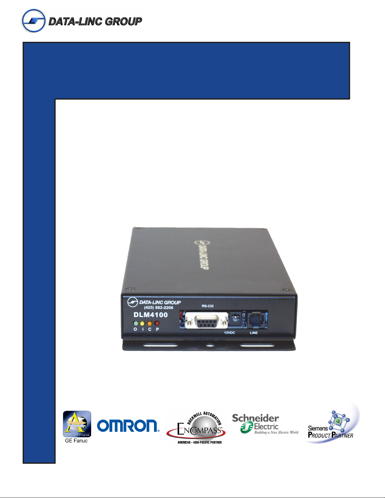
Compact Dial-Up Modem
OMMUNICATIONS
USER GUIDE
C
ATA
D
NDUSTRIAL
I
It is essential that all instructions contained in the User Guide are followed precisely to ensure proper operation of equipment.

Product User Guide
DATA-LINC GROUP
PN 161-09977-001B
DLM4100 User’s Manual
Operating Instructions
The DLM4100 is a compact dial-up modem designed and manufactured to operate in full industrial applications.
It is powered with an input voltage range of +8V to +15VDC. A 120VAC to unregulated 12VDC wall transformer
power supply has been provided (24VDC versions also available). The operating temperature range of this
device is 0° to 70° C. The (ET) Extended Temperature model is rated at -40° to +85° C.
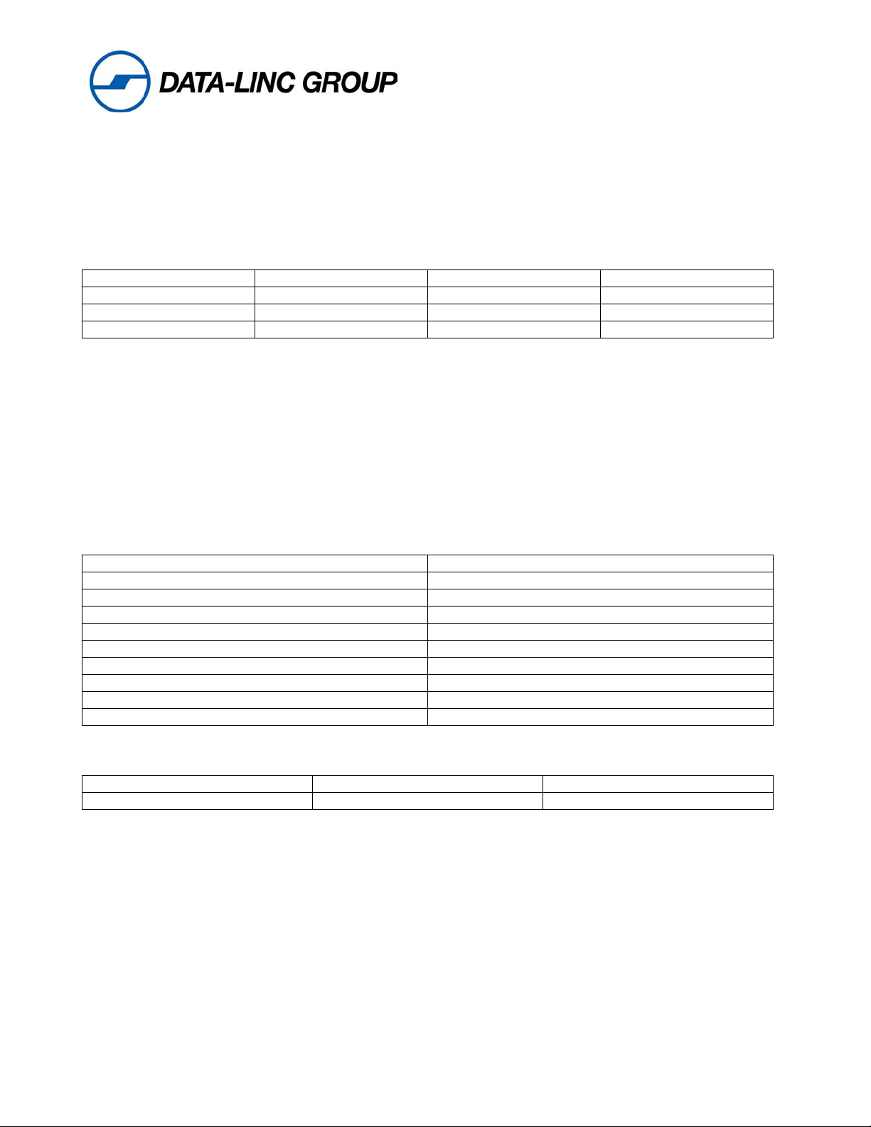
Any device connected to the modem must be set for a 10-bit word such as:
Data Bits Stop Bits Start Bits Parity
8 1 1 None
7 1 1 Even/Odd
7 2 1 None
Connections
Cable connections are all made on one end of the unit. The DB-9 female (see pinout below) on the left is for the
RS-232 data.
Note: RS-485 and RS-422 models are also available
The supplied wall transformer plugs into the barrel jack for supplying power to the unit. For alternate power
methods, see barrel jack pinout below. The RJ-11 jack on the right is the telephone line connection. Only the
center two lines are used.
DB-9 for the RS-232 data port. The port is setup as a DCE device and the pins are:
DB-9 Female Description
Pin 1 Carrier Detect
Pin 2 Data Out of modem RS-232 port
Pin 3 Data Into modem RS-232 port
Pin 4 N/C
Pin 5 Ground
Pin 6 N/C
Pin 7 N/C
Pin 8 N/C
Pin 9 N/C
The 12 VDC power jack plug for input power.
12VDC (P-5 Barrel Jack) Center Pin +8 to 15VDC in
Outer Ring Ground
P/N 161-09977-001B
2
DLM4100 User’s Manual
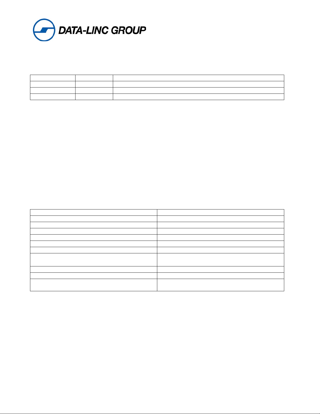
Indicators
There are four LED’s displayed out the front panel for status and diagnostics they are as follows:
(P) Power Red On indicates that the board is receiving power
(C) Carrier Amber On indicates that a connection has been made to another DLM4100
( I ) Data In Yellow On indicates that data is flowing into the serial port
(O) Data Out Green On indicates that data is flowing out to the serial port
Since the DLM4100 has been pre-configured at the factory for typical PLC to PC use, the only command strings
required are for dialing and hanging up. The command instruction to be entered in either PC or PLC
programmed for dial-up operation are listed below:
Dial String: ATDTx
Command Mode (escape sequence): +++
Hang up: ATH0
Note: Do not use any initialization string at all when commanding the modem to dial. Any command
other than the ATDT followed by the number being dialed can change the pre-configuration of the
DLM4100 and make it inoperative for PLC communications.
Specifications
Input Voltage +8 to 15 VDC
Current Consumption Max 260mA
Ring Voltage Detected 38 to 150 RMS
Ring Frequency Detected 15.3 to 68 Hz
Telephone Loop Current 20 to 100mA
Data Transmit Level -12 to –9.0 dBm
DTMF Transmit Level -2.5 dBm Avg. over 3 second interval
Operating Temperature Range
Enclosure Material 18 gauge steel
Enclosure Dimension 9.0” x 5.0” x 1.5” over mounting flanges
Weight 1.68 lb.
0° C to 70° C Standard Model
-40° C to 85° C Extended Temperature Model
.76 kg.
Note: The following pages are the AT Commands, Modem Registers, and Result codes for your
reference. In pre-configured systems from Data-Linc Group these values should not be changed.
P/N 161-09977-001B
3

DLM4100 User’s Manual
AT Commands
A- Answer Command – ATA forces the modem to immediately go off-hook and begin transmitting the
answer tone sequence.
Bn- Select Communications Standard – ATBn selects the modulation scheme used for connections
below 2400 bits per second.
n=0 Selects CCITT standards
n=1 Selects Bell standards
D- Dial Command – Below are the characters accepted in a dialing command.
0-9, #,* = Dialing Digits
L = Re-dial last number
P = Pulse dial
T = Tone dial
S=n = Dial stored number
W = Wait for dial tone
^ = Toggles state of calling tone
, = Pause for the duration of S8
@ = Wait for silence
! = Switch hook flash
; = Return to the command state
En- Command Echo – ATEn determines whether commands will be echoed back to the host.
n=0 Do not echo commands
n=1 Enable command echo
Hn – Switch Hook Control – ATHn opens and closes the modem’s hook switch.
n=0 Switch hook relay opens
n=1 Switch hook relay closes
Ln- Speaker Volume – ATLn Sets the amplitude of the modem’s audio output
n=0 Lowest speaker volume
n=1 Low speaker volume
n=2 Speaker remains on
n=3 Speaker off during dialing, on until carrier
Mn- Speaker Activity – ATMn determines when the modem’s audio output is active.
n=0 Speaker off
n=1 Speaker on until carrier received
n=2 Speaker remains on
n=3 Speaker off during dialing, on until carrier
P/N 161-09977-001B
4

DLM4100 User’s Manual
On- On Line – ATOn switches the modem from the command mode to the data mode.
n=0 Return on-line with no retrain
n=1 Initiate retrain returning on-line
Qn- Reponses – ATQn determines if the modem will issue responses
n=0 Send responses*
n=1 No responses
SR?- Interrogate Register – ATSr? request the current value in register Sr.
SR=n- Set Register Value – ATsr=n sets the value of register Sr to n
Vn- Result Codes – ATVn sets the modem to issue numeric or full word result codes
n=0 Numeric result codes
n=1 English word result codes
Wn- Connect Message Rate – ATWn determines whether the data rate reported in the Connect
response is the host date rate, the link data rate or whether both are provided along with the error control
and data compression protocols negotiated.
n=0 Send “Connect” at DTE rate
n=1 Report line speed, DTE speed and Link protocol
n=2 “Connect” reports Link speed
Xn- Result Code Set – ATXn selects which set of result codes the modem may send.
n=0 Result codes 0 to 4
n=1 Result codes 0 to 5 and 10
n=2 Result codes 0 to 6 and 10
n=3 Result codes 0 to 5, 7 and 10
n=4 Full result codes*
Zn- Reset – ATZn executes a soft reset to the modem and resets the modem configuration
n=0 Reset to user profile 0
n=1 Reset to user profile 1
&Cn- DCD Operation – AT&Cn determines the operation of the DCD output.
n=0 DCD is forced active
n=1 DCD indicates a valid carrier
P/N 161-09977-001B
5
 Loading...