

Data-Linc Group DLM4000 User Manual
DLM4000
Dial-Up/Leased Line Modem
OMMUNICATIONS
USER GUIDE
C
ATA
D
NDUSTRIAL
I
It is essential that all instructions contained in the User Guide are followed precisely to ensure proper operation of equipment.

Product User Guide
PN 161-09997-003A
Feb 2005

Table of Contents
DLM4000 User Guide
Page
Operation Instructions 3
Dia-Up Systems Example 5
Lesased Line System Example 5
LED Descriptions 6
○○○○○○○○○○○○○○○○○○○○○○○○○○○○○○○○○○○○○○○○○○○○○○○○
Connection Points 7
Verifying Operation 8
Setting Up Equipment for Bench Test Verification 9
Setting Up and Using HyperTerminal for Testing 10
Command Descriptions 13
Registers 17
○○○○○○○○○○○○○○○○○○○○○○○○○○○○○○○○○○○○○○○○○○○○○○○○○○○○
Technical Specifications 19
○○○○○○○○○○○○○○○○○○○○○○○○○○○○○○○○○○○○○○○○○○○○
○○○○○○○○○○○○○○○○○○○○○○○○○○○○○○○○○○○○○○○○○○○
○○○○○○○○○○○○○○○○○○○○○○○○○○○○○○○○○○○○○○○
○○○○○○○○○○○○○○○○○○○○○○○○○○○○○○○○○○○○○○○○○○○○○○○
○○○○○○○○○○○○○○○○○○○○○○○○○○○○○○○○○○○○○○○○○○○○○○○
○○○○○○○○○○○○○○○○○○○○○○○○○○○○
○○○○○○○○○○○○○○○○○○○○○○○○○○○○
○○○○○○○○○○○○○○○○○○○○○○○○○○○○○○○○○○○○○○○○○○○○
○○○○○○○○○○○○○○○○○○○○○○○○○○○○○○○○○○○○○○○○○○○○
Troubleshooting 20
Technical Support 22
Product Warranty 22
Return Material Authorization 22
Contact Information 22
○○○○○○○○○○○○○○○○○○○○○○○○○○○○○○○○○○○○○○○○○○○○○○○○
○○○○○○○○○○○○○○○○○○○○○○○○○○○○○○○○○○○○○○○○○○○○○○○
○○○○○○○○○○○○○○○○○○○○○○○○○○○○○○○○○○○○○○○○○○○○○○○
○○○○○○○○○○○○○○○○○○○○○○○○○○○○○○○○○○○○○○○○○
○○○○○○○○○○○○○○○○○○○○○○○○○○○○○○○○○○○○○○○○○○○○○○
Appendix A
Enclosure Dimensions 23
○○○○○○○○○○○○○○○○○○○○○○○○○○○○○○○○○○○○○○○○○○○○○
Appendix B
CCDF Module 24
○○○○○○○○○○○○○○○○○○○○○○○○○○○○○○○○○○○○○○○○○○○○○○○○○○
Appendix C
Auto Answer Module 25
○○○○○○○○○○○○○○○○○○○○○○○○○○○○○○○○○○○○○○○○○○○○○○
PN 161-09997-003A
Feb 2005
1

DLM4000 User Guide
2
PN 161-09997-003A
Feb 2005
DLM4000 User Guide
DLM4000 Operation Instructions
The DLM4000 has some requirements, which need to be met for proper operation and communication.
1. The standard DLM4000 modem requires 9 VAC and the 24V version requires 24 VDC.
2. The minimal current requirement for this modem is 300 mA.
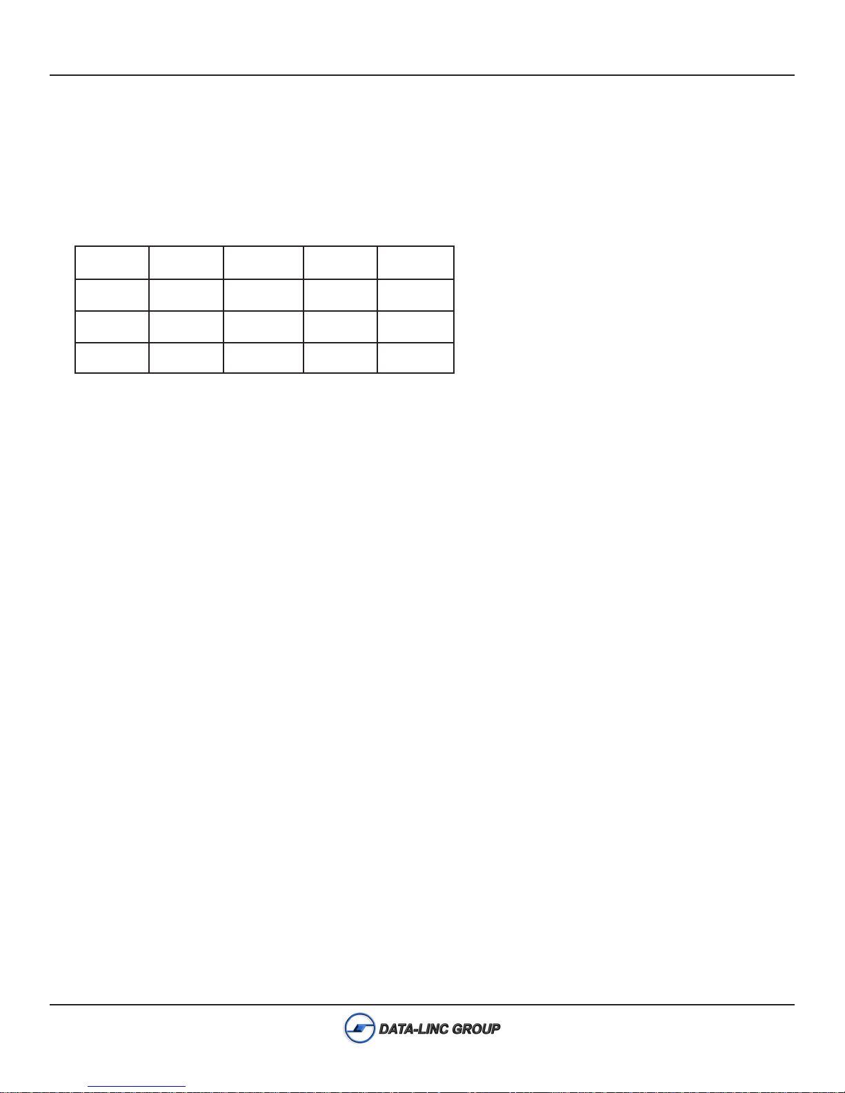
3. This modem uses a 10-bit word format only. Below is a table of reference to understand the data formats supported.
tiBtratSstiBataDytiraPtiBpotSstiBlatoT
18 enoN1 01
17 enoN2 01
17 ddO,nevE1 01
4. When using the DLM4000 on a leased line, there are some specifications to note. The leased line must be an analog
voice grade line or unshielded twisted pair, and must be two wire. The DLM4000 will not work on a digital line.
5. The DLM4000 is an asynchronous modem and therefore will not operate directly with synchronous protocols.
6. Handshaking lines such as DTR and RTS are not required for this modem and are ignored per the standard
configuration.
7. Error correction and compression are disabled in the standard configuration. Enabling these options may make
connecting with a PLC impossible.
8. To change modem mode or configuration, see modem setup on page 10.
PN 161-09997-003A
Feb 2005
3
DLM4000 User Guide
Connecting the DLM4000
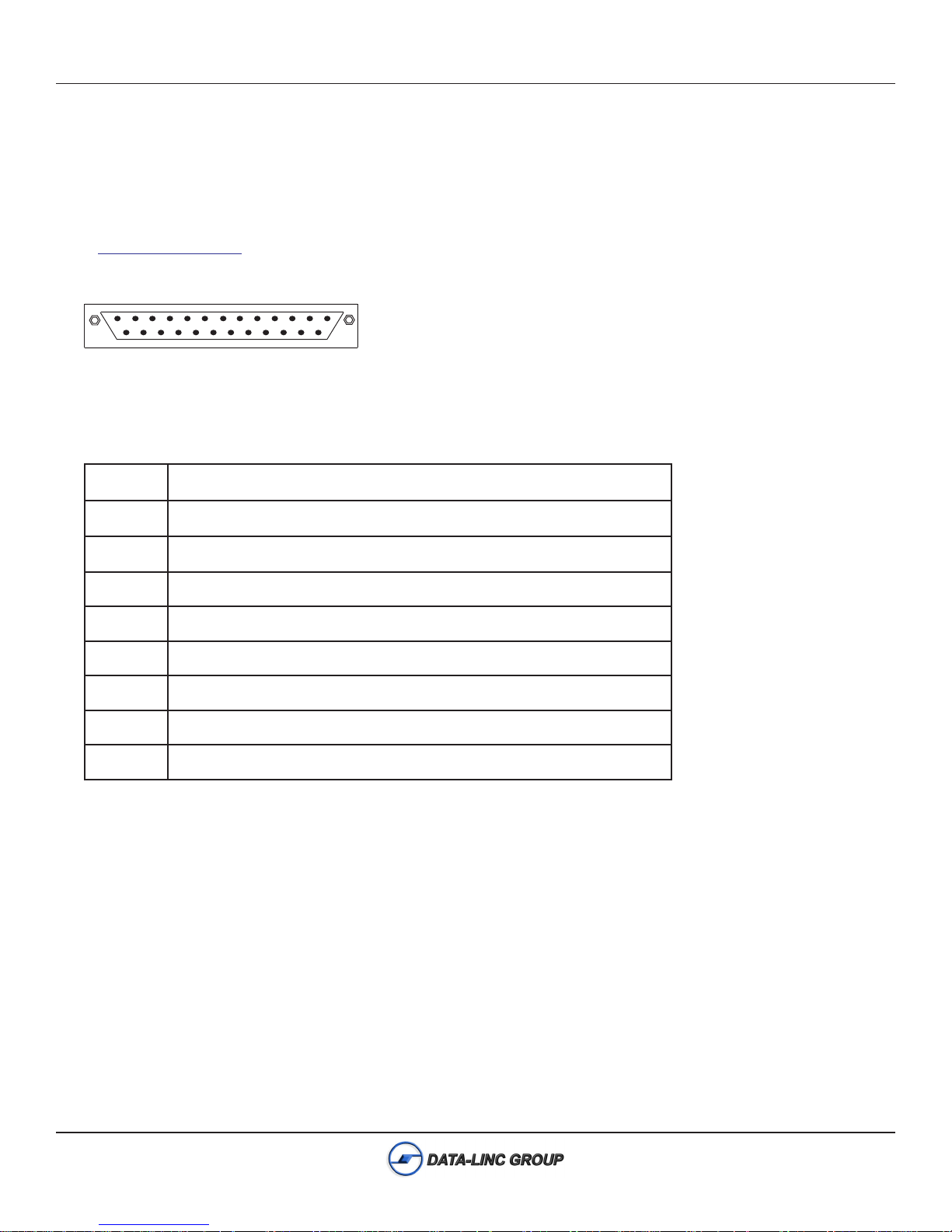
The DLM4000 provides an RS232 port for the connection to other devices. Below is a diagram of the serial port
configuration. It is important to use the proper cable when connecting equipment to the DLM4000. It is recommended that
only Data-Linc Group cables be used to ensure optimal performance. Commercial serial cables will not always provide
proper configuration. Should you require a cable(s), contact Data-Linc Group at (425) 882-2206 or
email sales@data-linc.com.
13 1
25
Pin Identification for the port
1niPdnuorGevitcetorP
2niPCLPehtmorfmedoMehtotniataD-ID
3niPCLPehtotnimedoMehtfotuoataD-OD
4niP tluafedybderongi,medoMotCLPmorfdnesottseuqeR-STR
5niP delbasidsilortnocwolf,CLPotmedoMmorfdnesotraelC-STC
6niPCLPotmedoMmorfydaertesataD-RSD
7niPdnuorGlangiS-DNG
8niPtceteDreirraC-DC
02niP tluafedybderongi,medoMotCLPmrofydaerlanimretataD-RTD
14
4
PN 161-09997-003A
Feb 2005
DLM4000 User Guide
DLM4000 Communications
The DLM4000 operates with many asynchronous protocols, some of which are listed below. The DLM4000 also provides
different options for connecting PLC’s and other equipment. Examples are provided on the following pages.
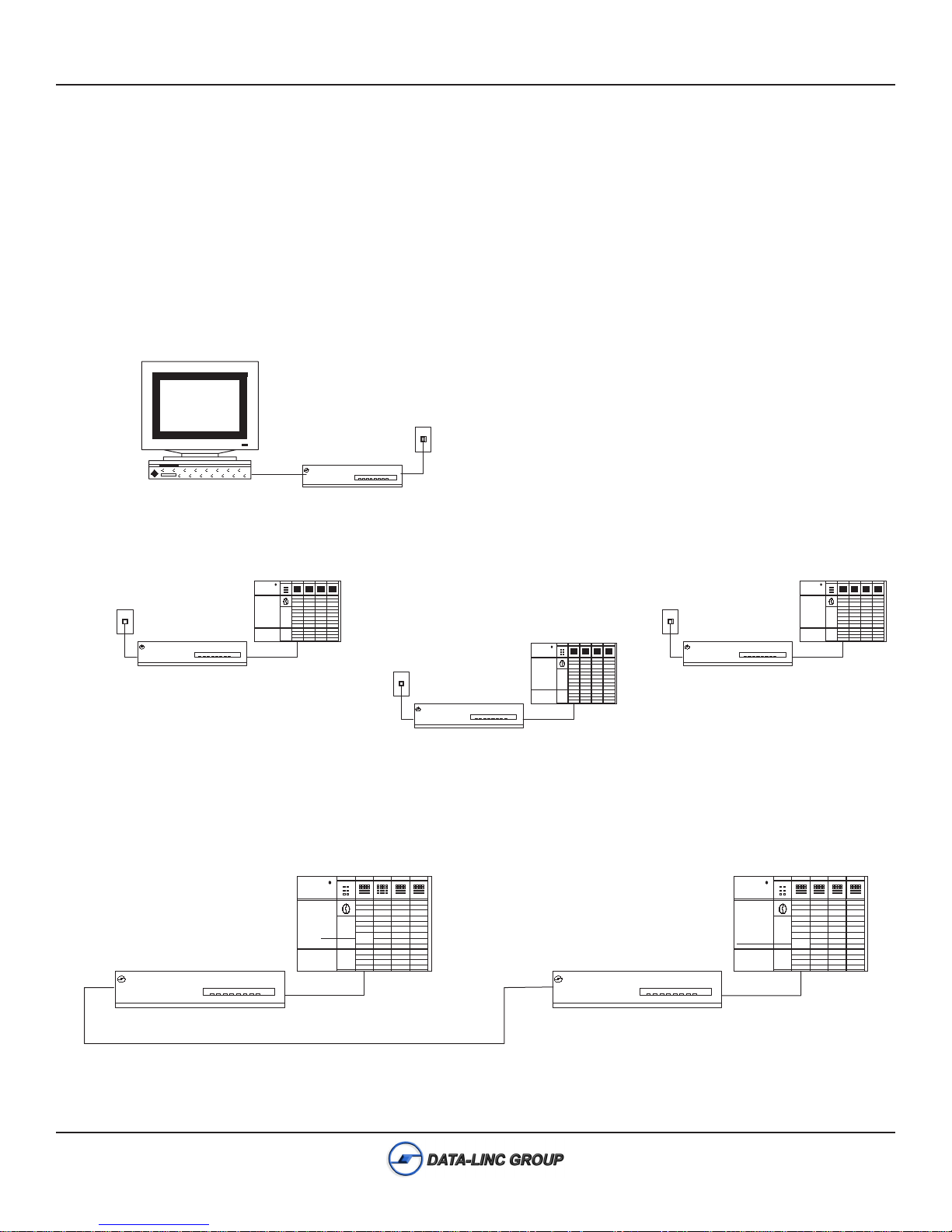
Dial-up System Example
Diagram 1
DLM4000 multipoint full duplex system using a PC master and PLC remotes. The system may involve dial-up polling or
periodic retrieval of data from remote locations.
Dial-UP Phone Connection
to Telco Network
RS-232
(425) 882-2206
DATA-LINC
GROUP
DLM4000
C T R
Master Station
Dial-UP Phone Connection
to Telco Network
(425) 882-2206
DATA-LINC
GROUP
DLM4000
C T R
PLC
RS-232
Dial-UP Phone Connection
to Telco Network
DATA-LINC
(425) 882-2206
GROUP
DLM4000
C T R
PLC
RS-232
Dial-UP Phone Connection
to Telco Network
DATA-LINC
(425) 882-2206
GROUP
DLM4000
C T R
PLC
RS-232
Leased Line System Example
Diagram 2
Leased or dedicated wire application. Multipoint operation is not an option. Only a point-to-point link is possible in Leased
Line Mode.
PLC
PLC
DATA-LINC
GROUP
(425) 882-2206
DLM4000
C T R
RS-232
Leased or Dedicated Line
PN 161-09997-003A
Feb 2005
DATA-LINC
GROUP
(425) 882-2206
DLM4000
C T R
RS-232
5
DLM4000 User Guide
Communications Description
Communication with the DLM4000 is possible in a multipoint configuration, but only through dial-up configuration. Per
diagram 1, it is possible to setup a dial-up polling operation. The link is a full-duplex link, which can be set up to 19200 bps.
Leased line mode is another option that can be used when dial-up lines are not available or desired, (see diagram 3). This
link is strictly a point-to-point full-duplex link. On unloaded lines, this link may be up to 20 miles. When the DLM4000
modems are being used on a loaded telephone company leased line the distance is unlimited. No ATDT commands are
required to connect. When the DLM4000 modems are set for leased line operation and powered up, they will connect and
achieve carrier. The communications rate may be set up to 19,200 bps.
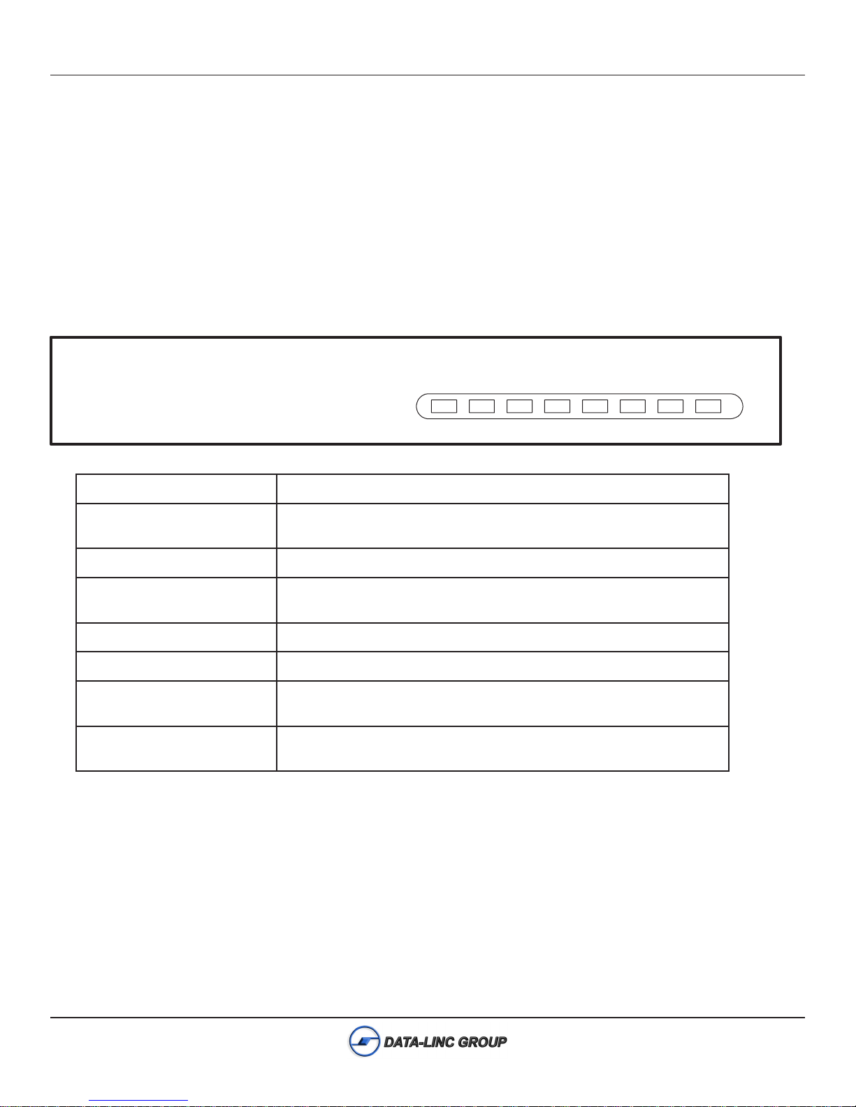
DLM4000 LED Descriptions
DATA-LINC GROUP
(425) 882-2206
(MR) (TR) (CD) (SD) (RD) (HS) (AA) (OH)
DLM4000
C T R
ydaeRmedoM)RM(
ydaeRlanimreTataD)RT(
tceteDreirraC)DC(
DXTroataDdneS)DS(
DXRroataDevieceR)DR(
deepShgiH)SH(
rewsnA-otuA)AA(
kooH-ffO)HO(
.detcetedsignir
nodenrutsimedomehtnehwsthgiL
cniL-ataDehT.detcetedsilangisRTDnehwsehsalF.RTDsadetoneD
.RTDerongiotsitluafedpuorG
.detcetedsireirracs'medometomerehtnehwsthgiL
romedometomerehtotatadgnidnessimedomehtnehwsehsalF
.tnempiuqeETDlacolehtmorfatadgniviecernehw
.tnempiuqeETDlacolmorfatadgniviecersimedomehtnehwsehsalF
.deepswolnehwffO.evobarospb0042sideepsenilnehwsthgiL
gnimocninehwsehsalF.rewsna-otuaroftessimedomehtnehwsthgiL
ehwffO.)kooh-ffo(enilenohpeletehtgnisusimedomehtnehwsthgiL
.)kooh-no(enilehtgnisutonsimedomeht
6
PN 161-09997-003A
Feb 2005
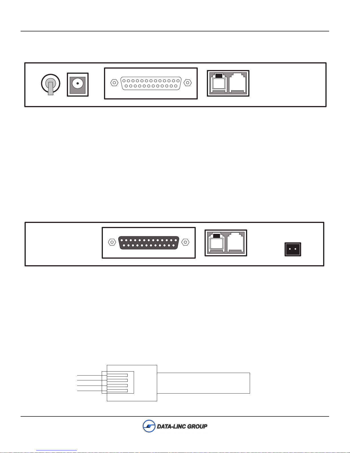
DLM4000 Connection Points
ON
DLM4000 User Guide
OFF
9VAC
PHONE
OUT
PHONE
IN
(PWR) The DLM4000 utilizes a toggle switch for powering the modem on and off.
(9VAC) The power connection is made with a barrel connector, which comes on the supplied power supply.
(RS232) The connection for the RS232 port on the modem is a DB25 female connection. Keep in mind that this device is
considered a DCE.
(PHONE OUT) For most applications a phone is not required. Data-Linc Group supplies the modem with an RJ11 plug in
this jack. This may be removed if connection of a phone to the modem is required.
(PHONE IN) Connection of the modem to the telephone company dial-up is done via this RJ11 jack. A dedicated or leased
line may also be used at this jack. Note that this unit is a two wire device and only the two center connection points of the
RJ11 jack are used.
DLM4000 24V Connection Points
PHONE
OUT
PHONE
IN
- +
24VDC
(24 VDC) The power connection to the DLM4000/24V is a terminal block. The connection points are designated in the above
diagram. There is no on or off switch on this version.
(RS232) The connection for the RS232 port on the modem is a DB25 female connection. This device is considered a
DCE.
(PHONE OUT) For most applications a phone is not required. Data-Linc Group supplies the modem with an RJ11 plug in
this jack. This may be removed if connection of a phone to the modem is required.
(PHONE IN) Connection of the modem to the telephone company dial-up is done via this RJ11 jack. A dedicated or leased
line may also be used at this jack. Note that this unit is a two wire device and only the two center connection points of the
RJ11 jack are used.
Not Connected
Connected
Connected
Not Connected
PN 161-09997-003A
Feb 2005
RJ11
Twisted Pair
7
 Loading...