

Page 1
These state-of-the-art panel meters are designed for
accurate measurement of the AC RMS voltage, AC
RMS current, frequency, active power and power
factor in single-phase systems. The current
transformer ratio can be set between 5/5A and
5000/5A via front panel buttons.
Devices have separate inputs for supply and
measurement.
The unit allows both manual selection of the display
channel and automatic scrolling.
Changing Display Selection:
By using the MENU button, voltage, current,
active power, power factor and frequency can be
selected and read from display. Every depression on
the MENU button will display the next
measurement.
60 seconds after the last keypress, the display will
return automatically to the default display mode.
However the defult display mode is selectable by
programming.
Any measured parameter can be set as the default
display. Automatic parameter scrolling is also
provided. Selections are stored into a non-volatile
memory and is not affected from power failures.
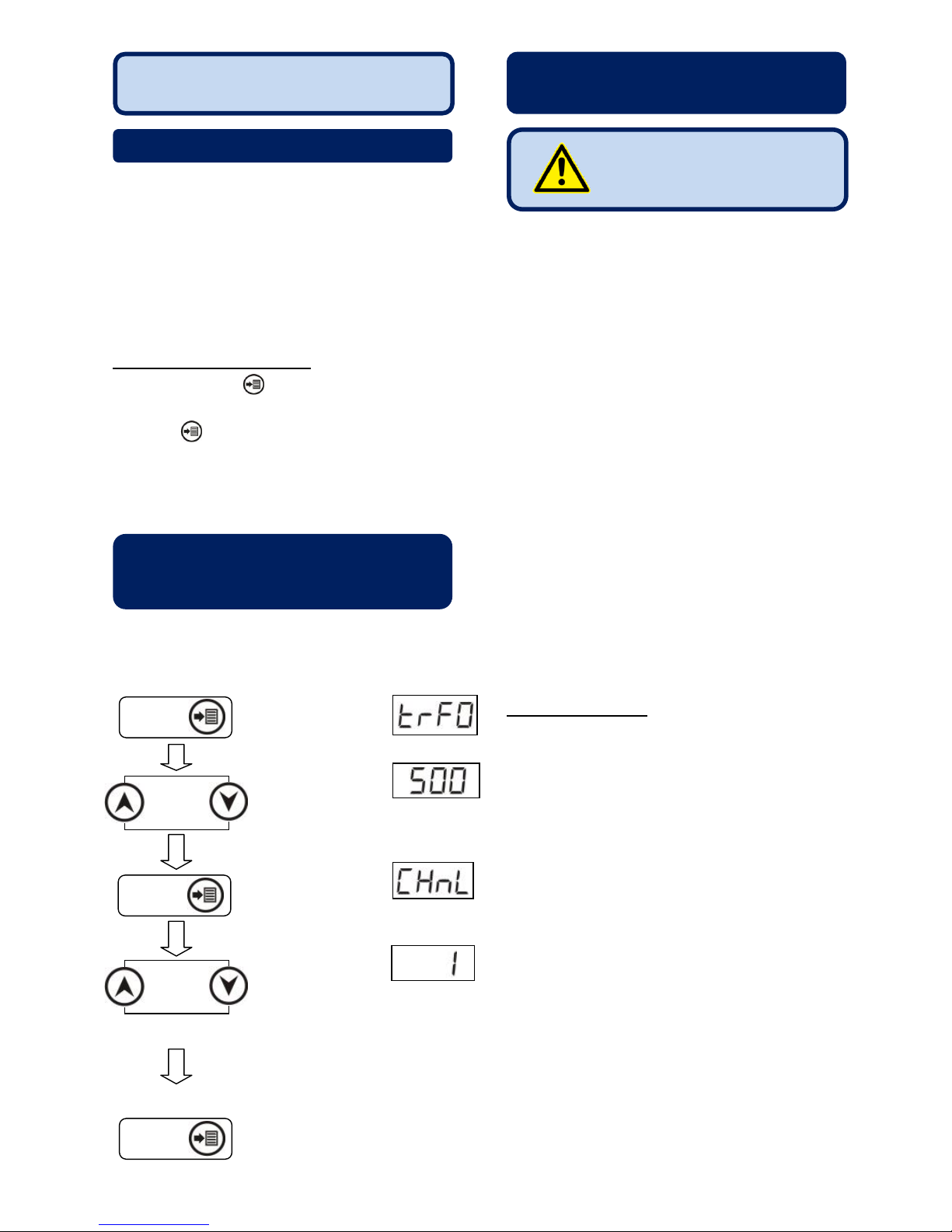
Press MENU button
for 3 sec.
Press Up or Down
buttons until
requested Current
Transformer Ratio is
displayed.
Press MENU button
for saving current
transformer ratio and
displaying default selection.
Press Up or Down
buttons until
requested display mode
appears.
0 – Auto scroll values every 5
sec.
1 =voltage 4= power factor
2= current 5= frequency
3= active power
Press MENU button for
saving default selection and
exit for settings.
Do not open the unit. There is no serviceable parts
inside.
Fuses must be connected to the power supply and
phase voltage inputs, in close proximity of the unit.
Fuses must be of fast type (FF) with a maximum
rating of 6A.
Disconnect all power before working on equipment.
When the unit is connected to the network do not
touch terminals.
Short circuit terminals of unused current
transformers.
Do not try to clean the device with solvent or the
like. Only clean with a dry cloth.
Verify correct terminal connections before applying
power.
Electrical equipment should be serviced only by
competent service personnel. No responsibility is
assured by the manufacturer or any of its
subsidiaries for any consequences arising out of
the use of this material.
Only for front panel flush mounting.
Before installation
Read the user manual carefully, determine the
correct connection diagram.
Remove all connectors and mounting brackets
from the unit, then pass the unit through the
mounting opening.
Put mounting brackets and tighten. Do not tighten
too much, this can brake the enclosure.
Make electrical connections with connectors
removed from sockets, then place connectors to
their sockets.
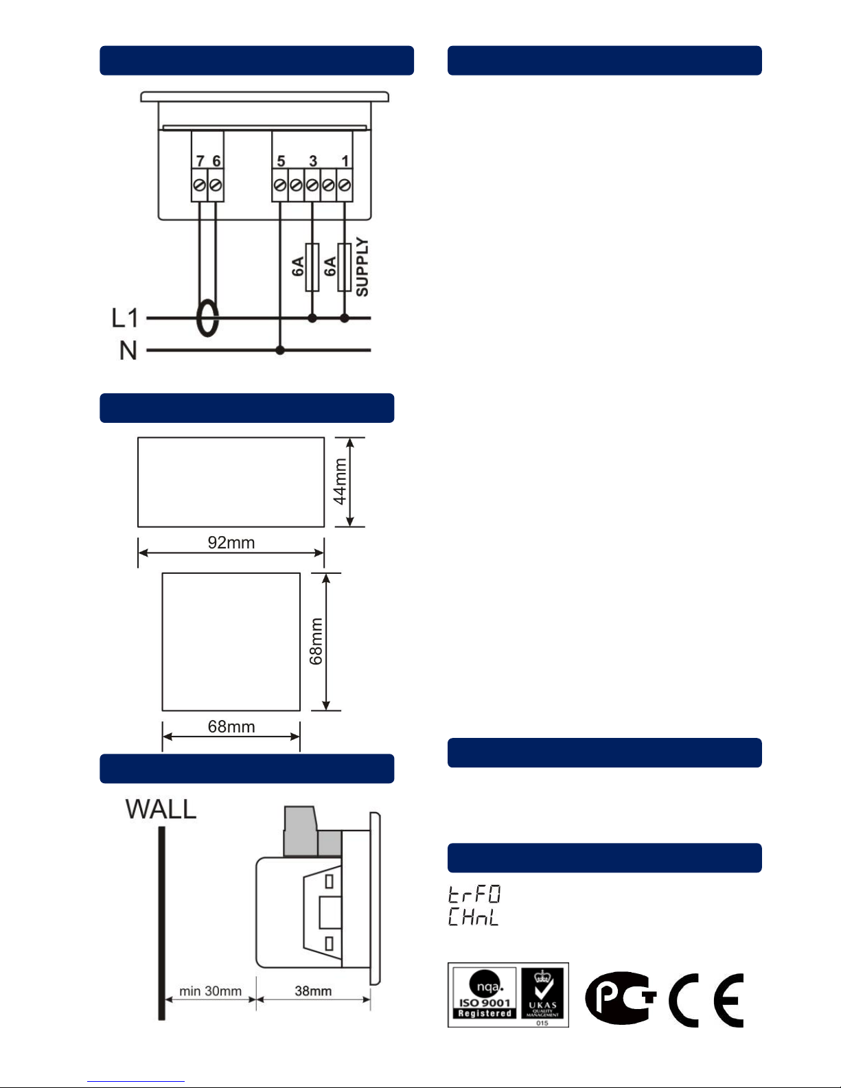
Note that the power supply terminal is separated
from measurement terminals, with common neutral
point.
Failure to follow below
instructions will result in
death or serious injury
PRECAUTIONS FOR INSTALLATION
AND SAFE USE
SETTING THE CURRENT
TRANSFROMER RATIO
AND THE DEFAULT DISPLAY
INTRODUCTION
DM-0101 DIGITAL MULTIMETER
72x72 & 96x48mm SIZES
DA-0101 DIGITAL AMMETER
96x96mm SIZES
MENU
MENU
MENU
Page 2
Power Supply Input: 170 - 275VAC
50 - 60Hz nominal (± 10%)
Different AC/DC supply values available.
Measurement Inputs:
10 - 300 V AC
0.2 – 5.50 A AC
30 - 100 Hz
Accuracy: Volts-Amps-Hz: 0.5% + 1 digit
kW : 1.0% + 2 digits
cos: 0.5% + 2 digits
Power Consumption: < 1.5W
Burden:
Voltage input: < 0.1VA per phase
Current input: < 1VA per phase
Operating Temperature: -40°C to +70 °C
Maximum Humidity: 95% non-condensing.
Degree of Protection: IP 54 (Front Panel)
IP 30 (Back panel)
Enclosure:
Non-flammable, ROHS compliant, high temperature
ABS/PC (UL94-V0)
Installation:
Flush mounting with rear retaining brackets
Dimensions:
96x48 models: 102x54x41mm (WxHxD)
72x72 models: 78x78x41mm (WxHxD)
Panel Cutout Dimensions:
96x48 models: 92x44mm
72x72 models: 68x68mm
Weight: 125 gr
EU Directives Conformity:
2006/95/EC (low voltage)
2004/108/EC (EMC)
Norms of reference:
EN 61010 (safety requirements)
EN 61326 (EMC requirements)
Pieces per Package: 24 Pcs
Package Size: 280 x 170 x 215mm (LxWxH)
Package Weight: 3.2 kg
= 500
= 0
FACTORY SETTINGS
PACKAGING INFORMATION
TECHNICAL SPECIFICATIONS
MOUNTING TOLERANCES
PANEL CUTOUT DIMENSIONS
CONNECTION DIAGRAM
 Loading...