

Page 1
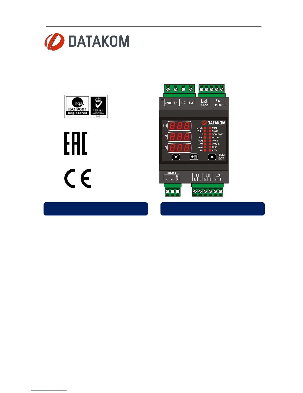
DKM-407 User Manual V-1.1
1
DKM-407
DIN RAIL TYPE
NETWORK ANALYZER
The DKM-407 is a DIN rail mounted precision
and low cost unit allowing measurement and
remote monitoring of AC parameters of a
distribution panel.
The unit is supplied between L1 and Neutral
terminals. Thanks to the supply range of 85305V, it is not affected by voltage fluctuations
and is capable of operating in any network.
The unit features an 32-bit ARM core
microcontroller. With a sampling rate of
4096s/s it reaches 0.5% precision.
The unit provides 1 programmable digital
input and 1 programmable relay output.
Input/output functions are selected from a list.
The isolated RS-485 MODBUS RTU data
port is not affected by ground potential
differences.
Program parameters may be uploaded from
a PC.
● True RMS measurements
● 0.5 % measurement precision
● Total harmonic distortion display
● Demand, Min and Max records
● Fully isolated RS-485 serial port
● MODBUS-RTU communications
● Programmable relay output
● Energy pulse output capability
● Isolated, programmable digital input
● kW and kVAr energy counters
● Hours run counter
● VT ratio for medium voltage applications
● Front panel programming
● Wide operating temperature range
● 2 part connectors
FEATURES
DESCRIPTION
MEASURED PARAMETERS
Page 2
DKM-407 Kullanım Kılavuzu V-1.1
2
Electrical equipment should be installed only by qualified
specialist. No responsibility is assured by the
manufacturer or any of its subsidiaries for any
consequences resulting from the non-compliance to
these instructions.
Check the unit for cracks and damages due to
transportation. Do not install damaged equipment.
Do not open the unit. There is no serviceable parts inside.
Fuses must be connected to phase voltage inputs, in
close proximity of the unit.
Fuses must be of fast type (FF) with a maximum rating of
6A.
Disconnect all power before working on equipment.
When the unit is connected to the network do not touch
terminals.
Short circuit terminals of unused current transformers.
Any electrical parameter applied to the device must be in
the range specified in the user manual.
Do not try to clean the device with solvent or the like.
Only clean with a dry cloth.
Verify correct terminal connections before applying
power.
Current Transformers must be used for current
measurement.
No direct connection allowed.
SAFETY NOTICE
Failure to follow below instructions will
result in death or serious injury
Page 3

DKM-407 Kullanım Kılavuzu V-1.1
3
Section
1. INSTALLATION
1.1. FRONT PANEL VIEW
1.2. MECHANICAL INSTALLATION
1.3. ELECTRICAL INSTALLATION
2. PUSHBUTTON FUNCTIONS
3. DISPLAY NAVIGATION
4. DEVICE CONFIGURATION
4.1. INTRODUCTION
4.2. RESETTING DEMAND VALUES
4.3. RESETTING ENERGY COUNTERS
4.4. RESETTING THE HOUR COUNTER
4.5. RESETTING ALARMS
4.6. SETTING THE DEFAULT SCREEN
4.7. SETTING THE CURRENT TRANSFORMER RATIO
4.8. SETTING THE VOLTAGE TRANSFORMER RATIO
4.9. SETTING HIGH AND LOW VOLTAGE LIMITS
4.10. SETTING HIGH AND LOW FREQUENCY LIMITS
4.11. SETTING THE OVERCURRENT LIMIT
4.12. SETTING HIGH AND LOW ACTIVE POWER LIMITS
4.13. SETTING HIGH AND LOW REACTIVE POWER LIMITS
4.14. SETTING HIGH AND LOW POWER FACTOR LIMITS
4.15. CONFIGURING THE DIGITAL INPUT
4.16. CONFIGURING THE RELAY OUTPUT
4.17. CONFIGURING THE ALARM DELAY
4.18. MODBUS PARAMETERS
4.19. ENERGY PULSE OUTPUT (kWh, kVArh) PARAMETERS
4.20. DISPLAYING THE FIRMWARE VERSION
4.21. CALIBRATION
4.22. LAMP TEST
5. MODBUS COMMUNICATIONS
5.1. DESCRIPTION
5.2. COMMANDS
5.3. PROGRAM PARAMETERS
5.4. MEASUREMENTS AND CONTROLLER RECORDS
6. TECHNICAL SPECIFICATIONS
TABLE OF CONTENTS
Page 4
DKM-407 Kullanım Kılavuzu V-1.1
4
Before installation:
Read the user manual carefully, determine the correct connection diagram.
Install the unit to the DIN rail.
Make electrical connections with plugs removed from sockets, then place plugs to their
sockets.
Note that the power supply terminal is separated from measurement terminals.
Below conditions may damage the device:
Incorrect connections.
Incorrect power supply voltage.
Voltage at measuring terminals beyond specified range.
Current at measuring terminals beyond specified range.
Connecting or removing data terminals when the unit is powered-up.
Overload or short circuit at relay outputs
Voltage applied to digital inputs over specified range.
High voltage applied to communication port.
Below conditions may cause abnormal operation:
Power supply voltage below minimum acceptable level.
Power supply frequency out of specified limits
Phase order of voltage inputs not correct.
Current transformers not matching related phases.
Current transformer polarity incorrect.
Current Transformers must be used for current
measurement.
No direct connection allowed.
1. INSTALLATION
Page 5
DKM-407 Kullanım Kılavuzu V-1.1
5
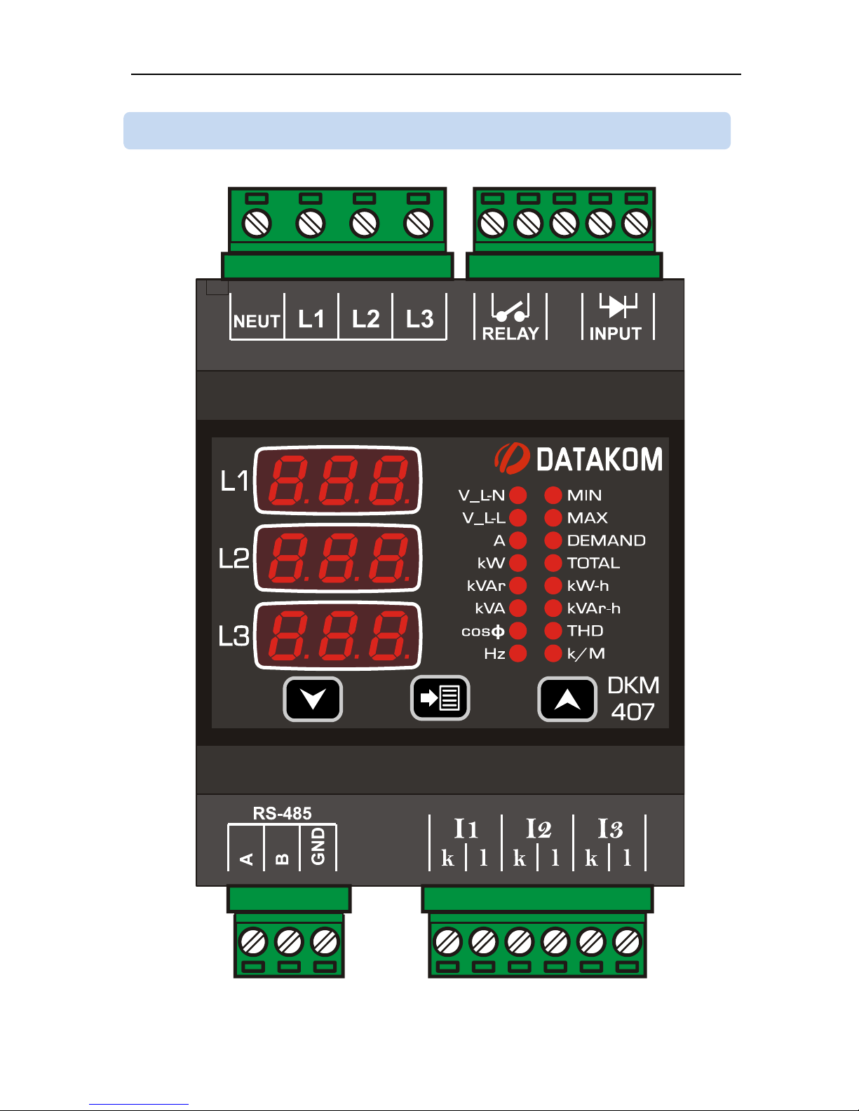
1.1 FRONT PANEL VIEW
Page 6
DKM-407 Kullanım Kılavuzu V-1.1
6
Although the unit is protected against electromagnetic disturbance, excessive disturbance
can affect the operation, measurement precision and data communication quality.
ALWAYS remove plug connectors when inserting wires with a screwdriver.
Fuses must be connected to phase voltage inputs, in close proximity of the unit.
Fuses must be of fast type (FF) with a maximum rating of 6A.
Use cables of appropriate temperature range.
Use adequate cable section, at least 0.75mm2 (AWG18).
For current transformer inputs, use at least 1.5mm2 section (AWG15) cable.
The current transformer cable length should not exceed 1.5 meters. If longer
cable is used, increase the cable section proportionally.
Follow national rules for electrical installation.
Current transformers must have 5A output.
Current Transformers must be used for current
measurement.
No direct connection allowed.
Do not install the unit close to high electromagnetic
noise emitting devices like contactors, high current
busbars, switchmode power supplies and the like.
1.3 ELECTRICAL INSTALLATION
Page 7
DKM-407 Kullanım Kılavuzu V-1.1
7
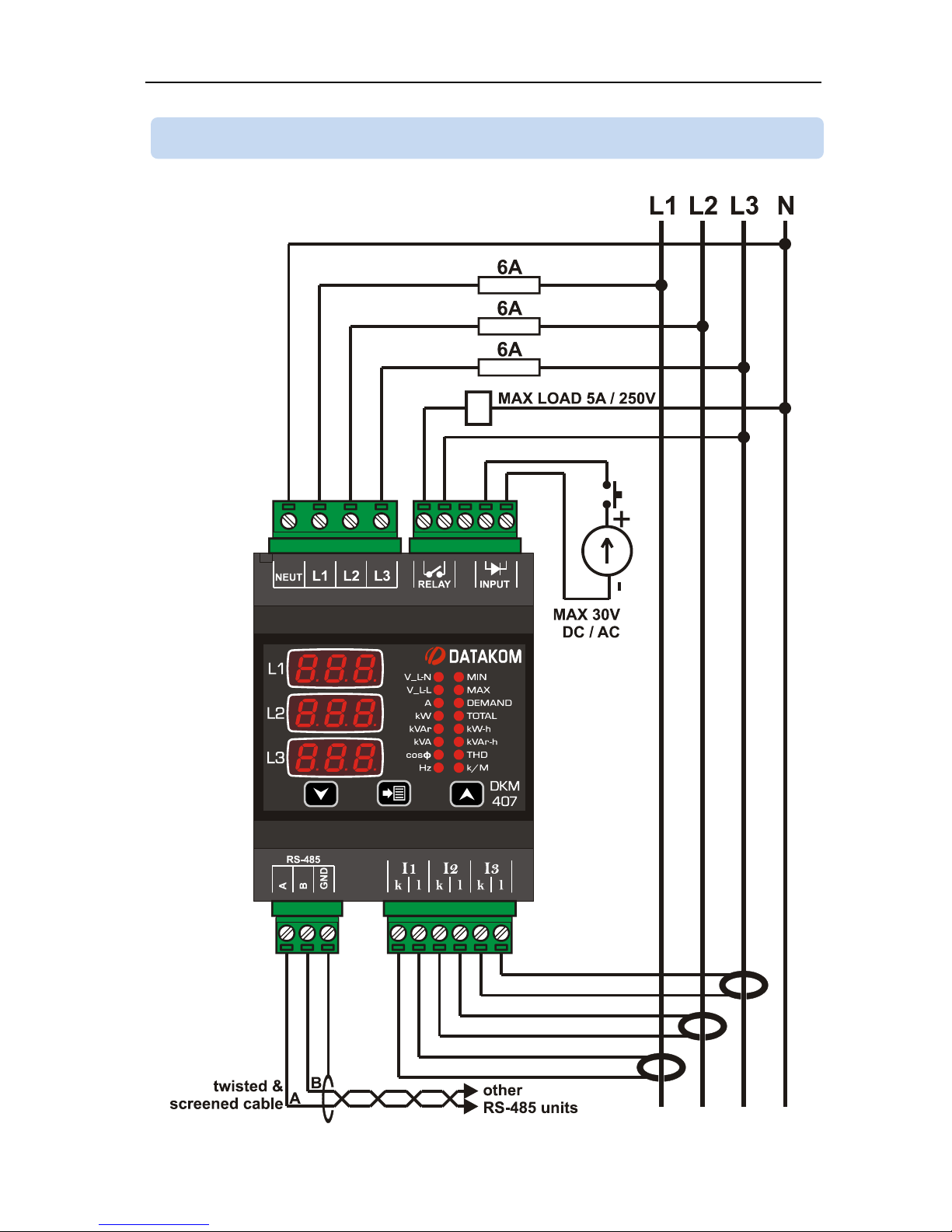
1.4 CONNECTION DIAGRAM
Page 8
DKM-407 Kullanım Kılavuzu V-1.1
8
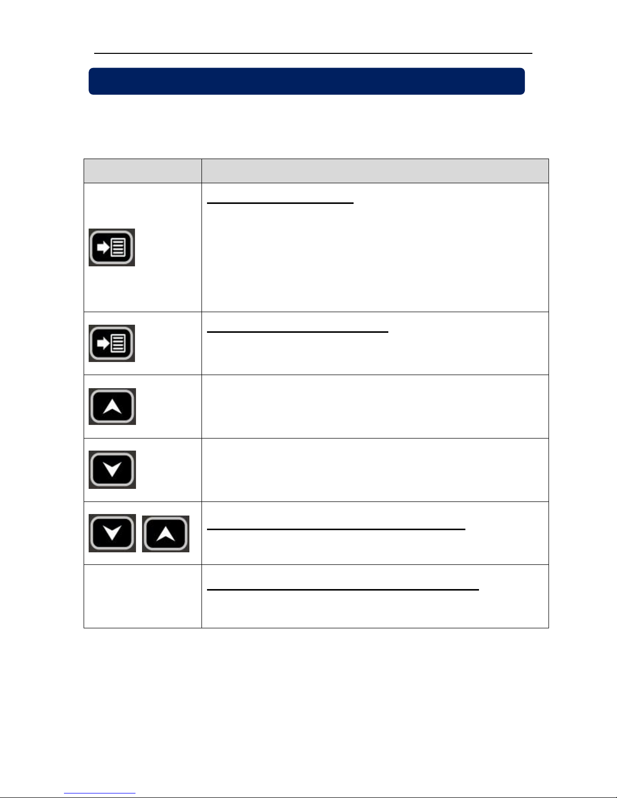
Three buttons on the front panel provide access to configuration and measurement
screens.
BUTTON
FUNCTION
Selects display context
THD display
Minimum values display
Maximum values display
Demand display
If all leds are off then actual measurements
display.
HELD PRESSED FOR 5 SEC:
resets min-max values and displays minimum phase-
to-neutral voltages.
Upper screen
or
Increase related value (configuration mode)
Lower screen
or
Decrease related value (configuration mode)
HELD PRESSED TOGETHER FOR 2 SEC:
Enters configuration mode.
IF NO BUTTON PRESSED FOR 5 MINUTES:
returns to the main display screen
2. PUSHBUTTON FUNCTIONS
Page 9
DKM-407 Kullanım Kılavuzu V-1.1
9
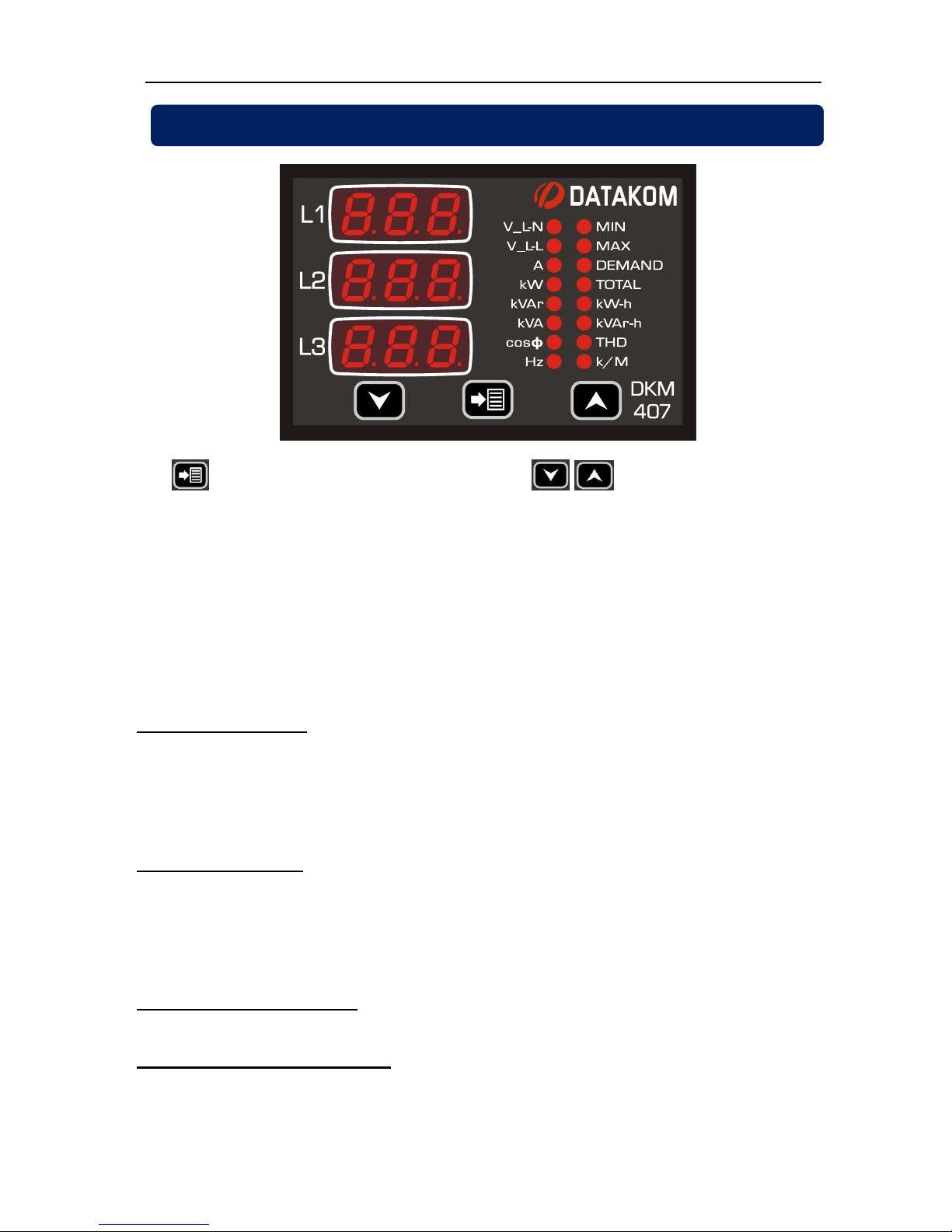
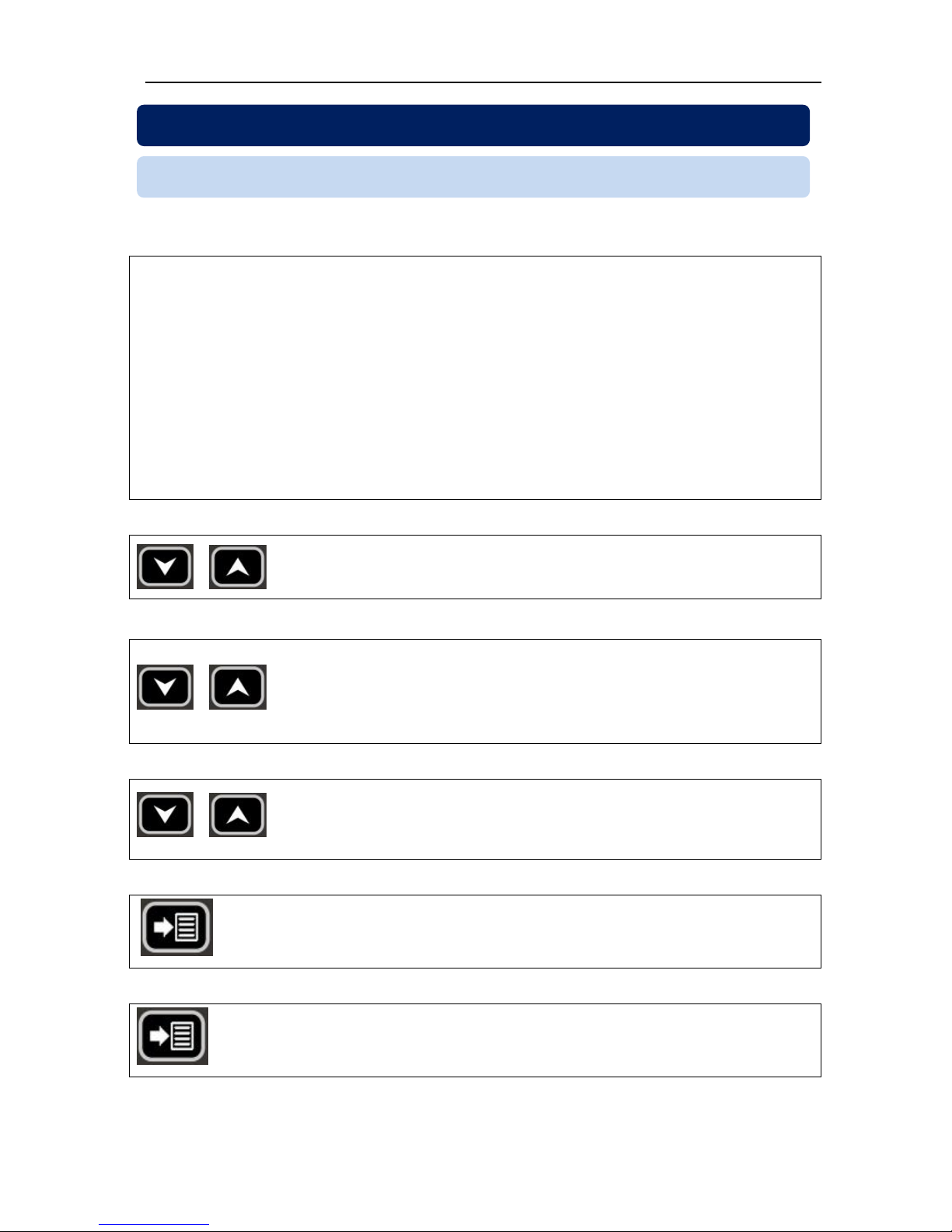
The button will select the display context and buttons will navigate
between possible values of this context.
Kilo/Mega (k/M) led will turn on if the displayed value is in kA/kV/MW/MVA/MVAr.
TOTAL led will turn on when displaying total values.
Normally, the led indicating the values on display will be on. Other leds will turn off. If total
working hours is displayed then only the TOTAL led will turn on.
When displaying voltage, current, THD, power factor, etc.. each display will show the
value related to one phase. When total values are displayed, depending on the length of
the data to display, all 3 displays may be used.
Display of currents: If the greatest current value to display is larger than 999A then the
k/M (kilo/mega) led will turn on, otherwise it will turn off. When the k/M led is off, if the
greatest current value is below 100A then currents will be displayed with 0.1A precision,
otherwise they will be displayed with 1A precision. When the k/M led is on, if the greatest
current value is below 10kA then currents will be displayed with 0.01kA precision,
otherwise they will be displayed with 0.1kA precision.
Display of voltages: If the greatest voltage value to display is larger than 999V then the
k/M (kilo/mega) led will turn on, otherwise it will turn off. When the k/M led is off, voltages
will be displayed with 1V precision. When the k/M led is on, if the greatest voltage value is
below 10kV then voltages will be displayed with 0.01kV precision, between 10kV and
99.9kV they will be displayed 0.1kV precision and above 100kV they will be displayed with
1kV precision.
Display of kW, kVA, kVAr: Depending on the values, they will be displayed with 0.1k or
1k or 0.01M precision.
Display of kWh, kVArh, Hours: Values are displayed with a precision of 0.1 k (or hour).
3. DISPLAY NAVIGATION
Page 10
DKM-407 Kullanım Kılavuzu V-1.1
10
In order to offer the maximum flexibility to the user, the unit has several configurable
parameters.
Device Configuration
Default display configuration
Measurement Configurations
Resetting Demand Values
Clearing Counters
Resetting Alarms
Setting the CT ratio
Setting the VT ratio
Setting alarm limits
Input / Output Configuration
Input Configuration
Relay Configuration
Alarm delay
Modbus parameters
Device Calibration
In order to enter the configuration menu,
hold both MENU buttons pressed for 2 seconds.
In order to exit the configuration menu,
hold both MENU buttons pressed for 2 seconds.
If no button is pressed, the unit will automatically
close the configuration menu after 1 minute.
Parameter values are increased / decreased with
MENU buttons. Holding the button pressed will
increase / decrease with larger steps.
Pressing the SET button will save the current
parameter and display the next parameter.
Holding the SET button pressed for 2 seconds will
display the previous parameter.
4.1 INTRODUCTION
4. DEVICE CONFIGURATION
Page 11
DKM-407 Kullanım Kılavuzu V-1.1
11
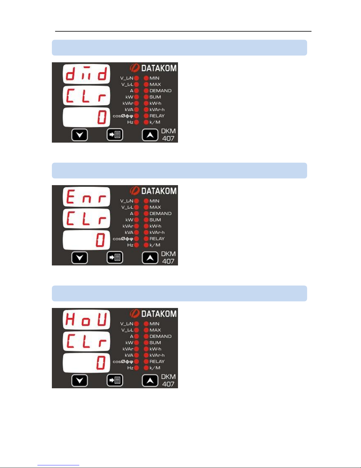
Parameter value:
0: No action
1: Reset Demand values
Setting this parameter to 1 will reset demand
values.
The parameter value is not stored into
memory and reads always 0.
Parameter value:
0: No action
1: Reset kWh and kVArh counters
Setting this parameter to 1 will reset
powermeter counters.
The parameter value is not stored into
memory and reads always 0.
Parameter value:
0: No action
1: Reset hour counter
Setting this parameter to 1 will reset the
hour counter.
The parameter value is not stored into
memory and reads always 0.
4.4 RESETTING THE HOUR COUNTER
4.3 RESETTING ENERGY COUNTERS
4.2 RESETTING DEMAND VALUES
Page 12
DKM-407 Kullanım Kılavuzu V-1.1
12
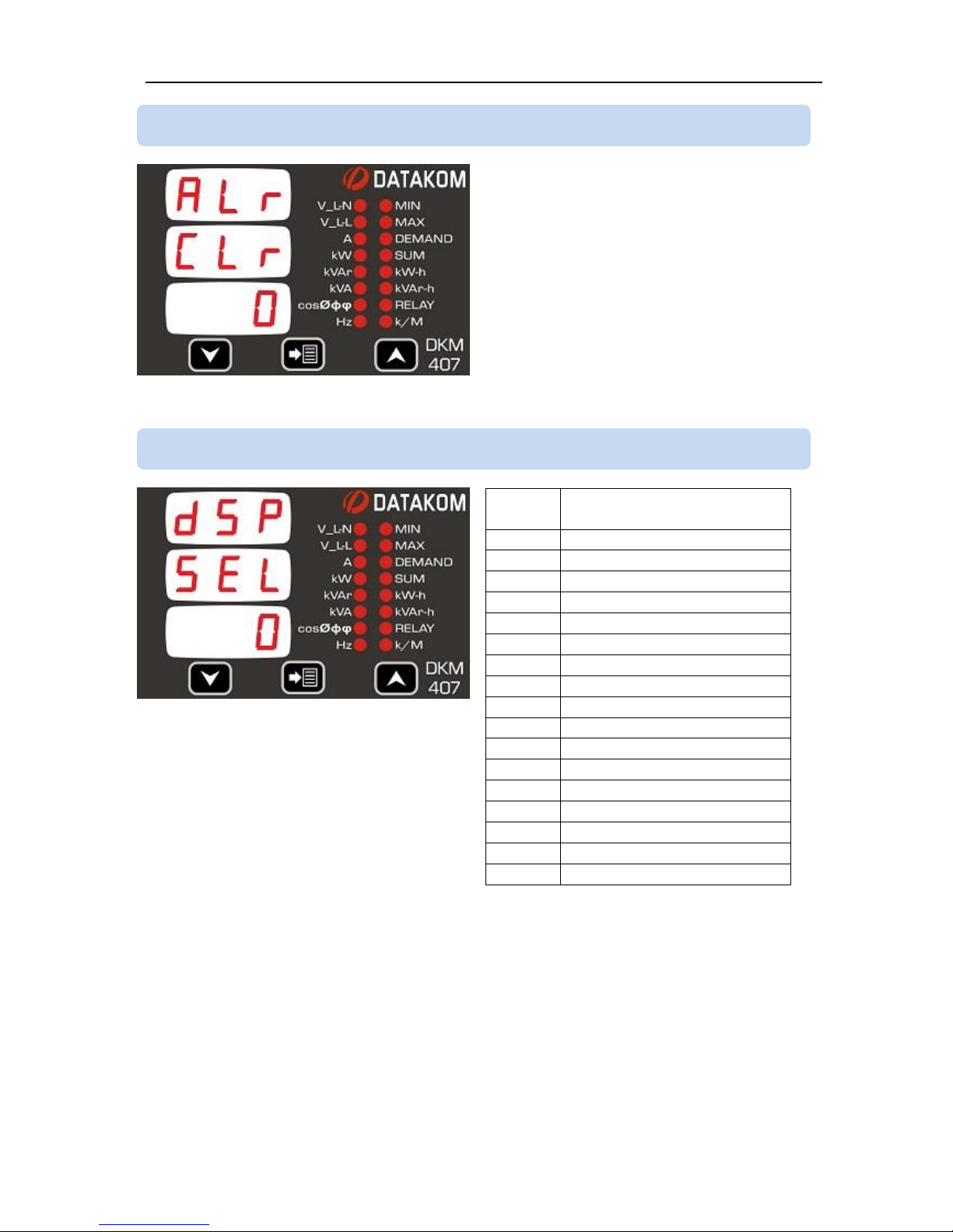
Parameter value:
0: No action
1: Reset alarms
Setting this parameter to 1 will reset
existing alarms.
The parameter value is not stored into
memory and reads always 0.
This parameter selects the default screen
that the unit returns 5 minutes after any
key is pressed.
Setting this parameter to 0 will cancel the
default screen.
Param.
değeri
Göstergeler
0
no change
1
Voltages L-N
2
Voltages L-L
3
Currents
4
Total current
5
Phase kW
6
Total kW
7
Phase kVAr
8
Total kVAr
9
Phase kVA
10
Total kVA
11
Phase cosø
12
Total cosø
13
Frequency
14
kWh counter
15
kVArh counter
16
Hours counter
4.6 SETTING THE DEFAULT SCREEN
4.5 RESETTING ALARMS
Page 13
DKM-407 Kullanım Kılavuzu V-1.1
13
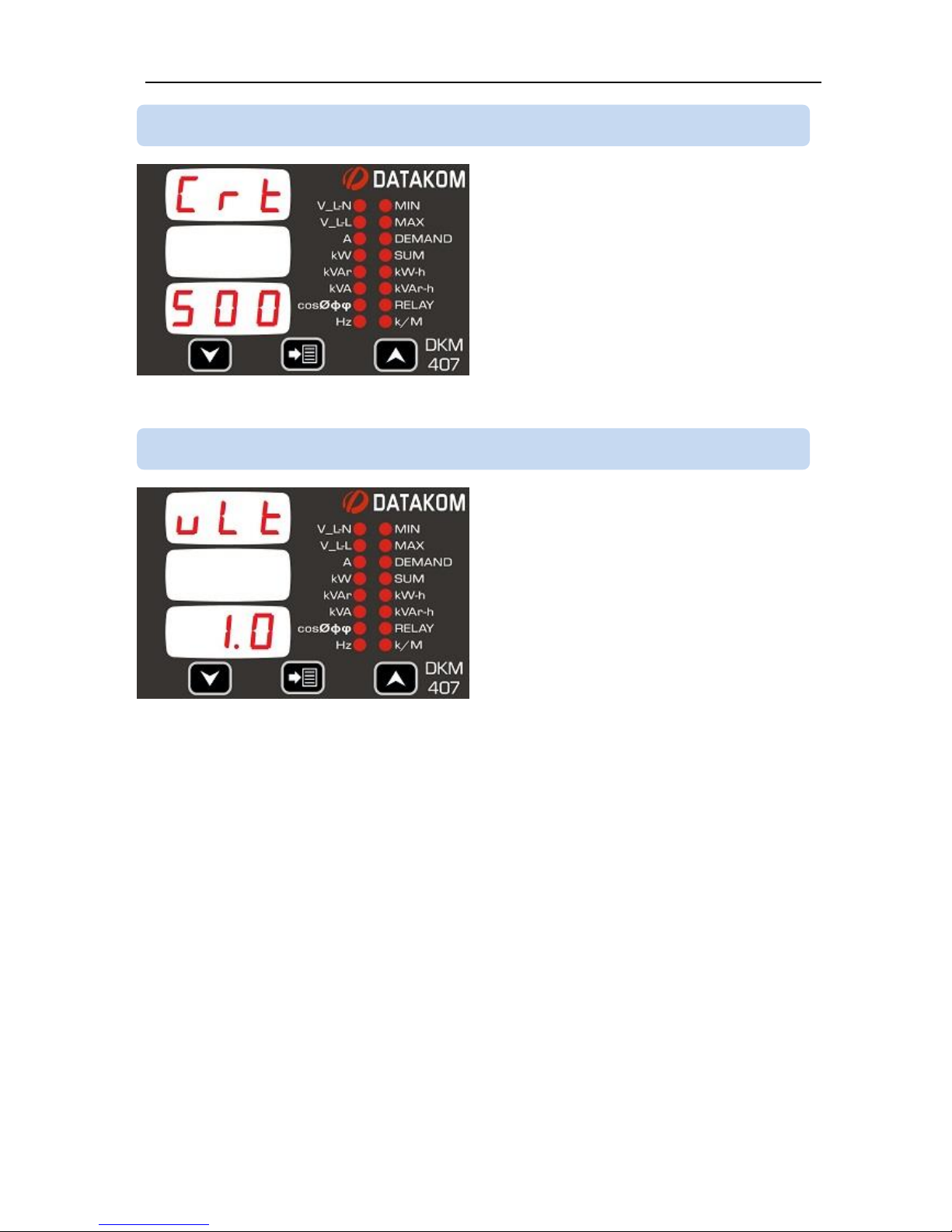
This parameter sets the primary rating of
current transformers.
Current transformer secondary rating
should be 5 Amps.
The factory set default value is 500/5A.
Acceptable values are 5/5A to 5000/5A.
This parameter sets the ratio of voltage
transformers.
All voltage and power measurements will
be displayed after multiplication with this
parameter.
The factory set default value is 1.0
Acceptable values are 0.1 to 200.0
4.8 SETTING THE VOLTAGE TRANSFORMER RATIO
4.7 SETTING THE CURRENT TRANSFORMER RATIO
Page 14
DKM-407 Kullanım Kılavuzu V-1.1
14
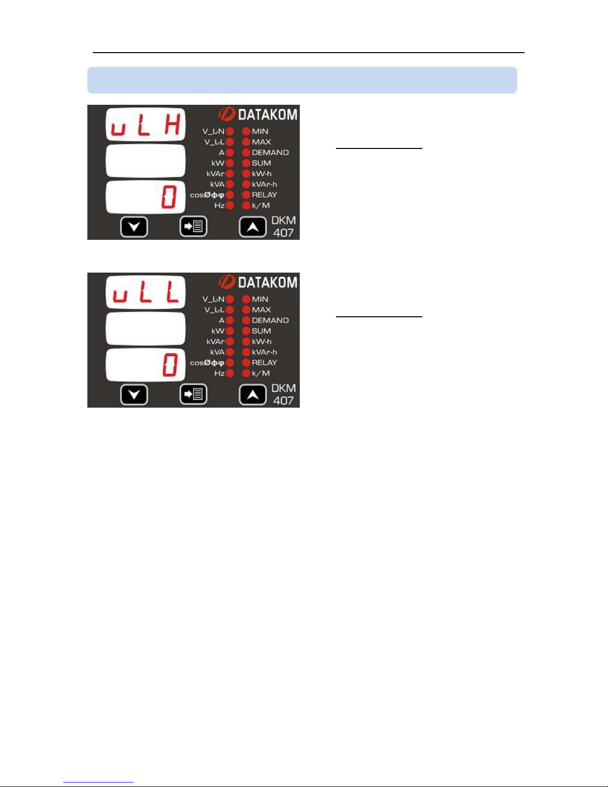
This parameter sets the high limit for high
voltage alarm.
Only phase to neutral voltages are
monitored and generate alarms.
If the parameter is set to 0 then no high
voltage alarm will occur.
The factory set default value is 0
Acceptable values are 0 to 12’000volts
This parameter sets the low limit for low
voltage alarm.
Only phase to neutral voltages are
monitored and generate alarms.
If the parameter is set to 0 then no low
voltage alarm will occur.
The factory set default value is 0
Acceptable values are 0 to 12’000volts
4.9 SETTING HIGH AND LOW VOLTAGE LIMITS
Page 15
DKM-407 Kullanım Kılavuzu V-1.1
15
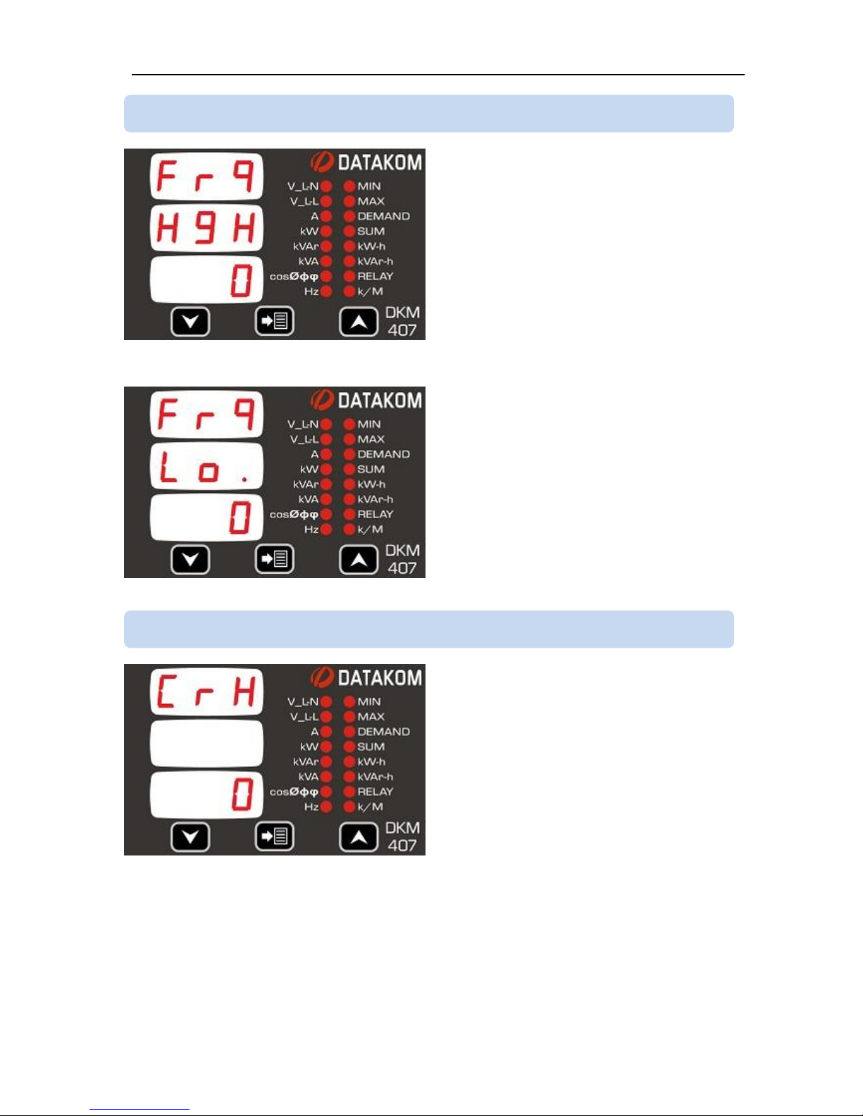
This parameter sets the high limit for high
frequency alarm.
If the parameter is set to 0 then no high
frequency alarm will occur.
The factory set default value is 0
Acceptable values are 0 to 400Hz
This parameter sets the low limit for low
frequency alarm.
If the parameter is set to 0 then no low
frequency alarm will occur.
The factory set default value is 0
Acceptable values are 0 to 400Hz.
This parameter sets the high limit for
overcurrent alarm.
If the parameter is set to 0 then no
overcurrent alarm will occur.
The factory set default value is 0
Acceptable values are 0 to 5000Amps.
4.11 SETTING THE OVERCURRENT LIMIT
4.10 SETTING HIGH AND LOW FREQUENCY LIMITS
Page 16
DKM-407 Kullanım Kılavuzu V-1.1
16
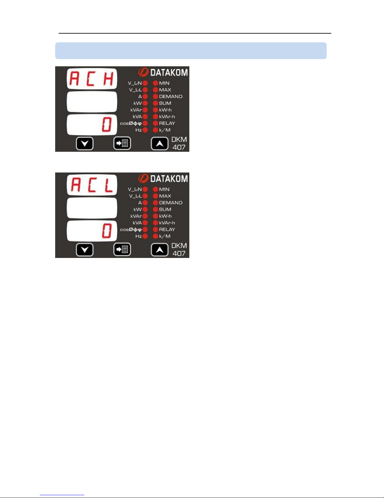
This parameter sets the high limit for
excess active power alarm.
If the parameter is set to 0 then no excess
active power alarm will occur.
The factory set default value is 0
Acceptable values are 0 to 6500kW.
This parameter sets the low limit for low
active power alarm.
If the parameter is set to 0 then no low
active power alarm will occur.
The factory set default value is 0
Acceptable values are 0 to 6500kW.
4.12 SETTING HIGH AND LOW ACTIVE POWER LIMITS
Page 17
DKM-407 Kullanım Kılavuzu V-1.1
17
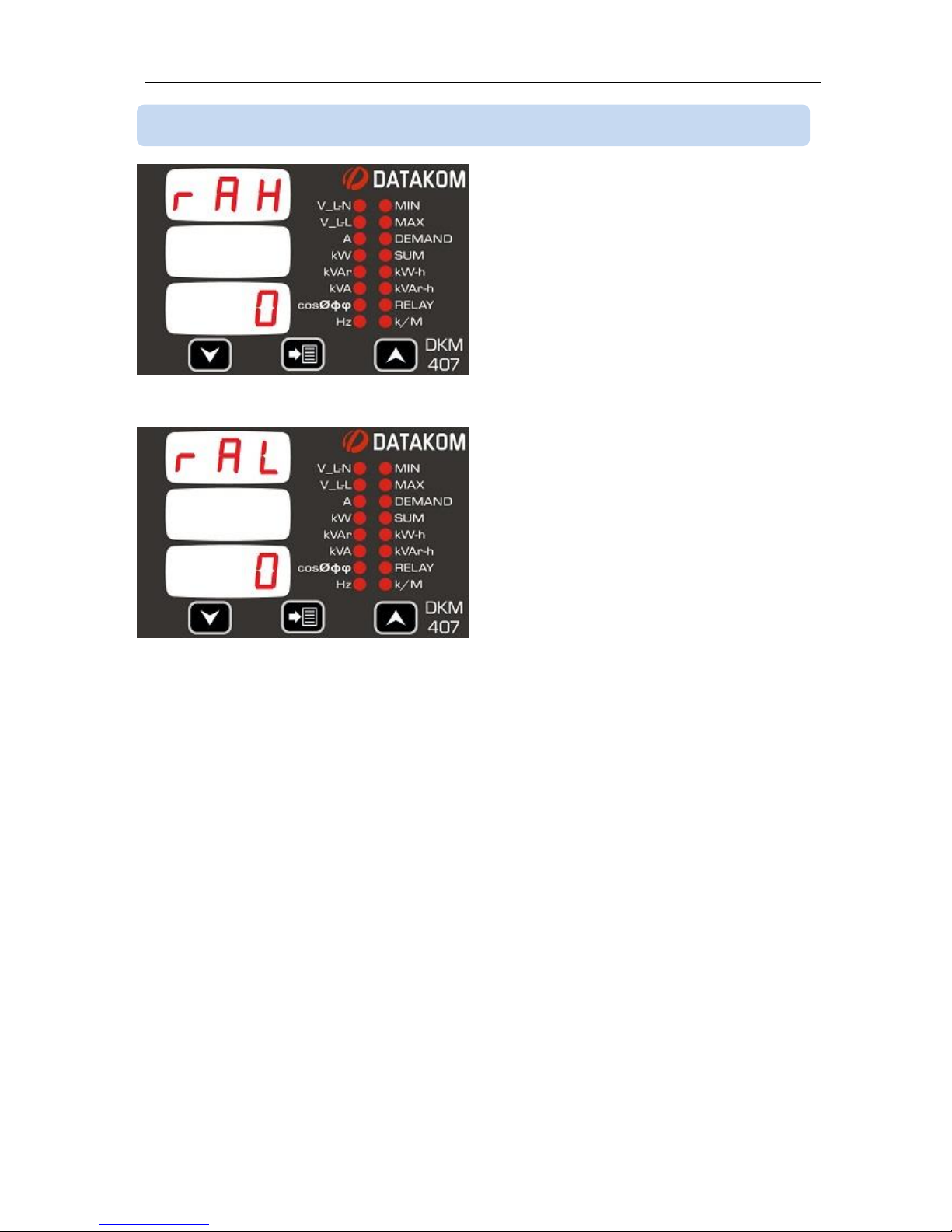
This parameter sets the high limit for
excess reactive power alarm.
If the parameter is set to 0 then no excess
reactive power alarm will occur.
The factory set default value is 0
Acceptable values are 0 to 6500kVAr.
This parameter sets the low limit for low
reactive power alarm.
If the parameter is set to 0 then no low
reactive power alarm will occur.
The factory set default value is 0
Acceptable values are 0 to 6500kVAr.
4.13 SETTING HIGH AND LOW REACTIVE POWER LIMITS
Page 18
DKM-407 Kullanım Kılavuzu V-1.1
18
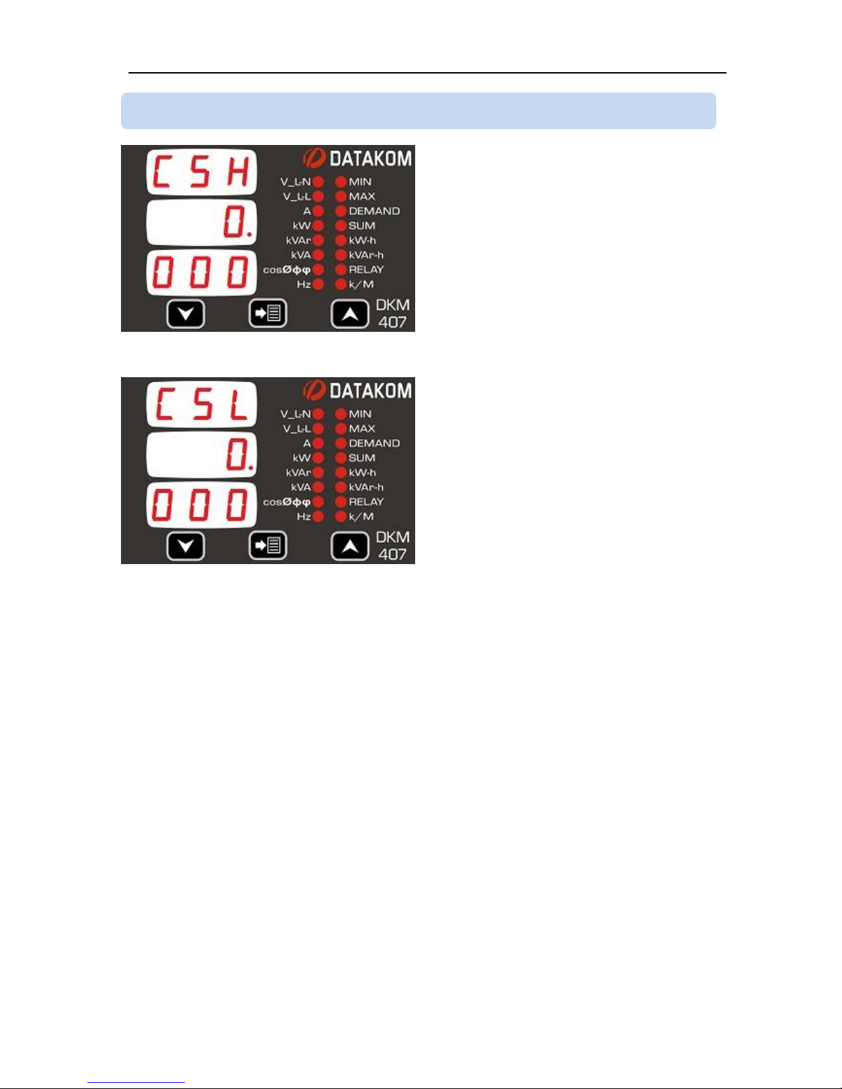
This parameter sets the high limit for high
cosø alarm.
If the parameter is set to 0.000 then no high
cosø alarm will occur.
The factory set default value is 0.000
Acceptable values are 0.000 to 1.000
This parameter sets the low limit for low
cosø alarm.
If the parameter is set to 0.000 then no low
cosø alarm will occur.
The factory set default value is 0.000
Acceptable values are 0.000 to 1.000
4.14 SETTING HIGH AND LOW POWER FACTOR LIMITS
Page 19
DKM-407 Kullanım Kılavuzu V-1.1
19
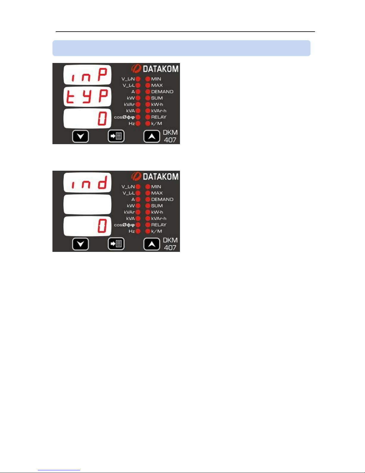
This parameter sets the active status of the
digital input signal.
0: input active when signal applied
1: input active when signal removed
The input signal is 5 to 30V AC or DC
applied between terminals with the polarity
shown in the connection diagram.
The factory set default value is 0.
This parameter sets the detection delay of
the digital input signal in miliseconds.
This delay is necessary to prevent spurious
signal detection due to electrical noise.
The factory set default value is 1ms.
Acceptable values are 1 to 1000ms.
4.15 CONFIGURING THE DIGITAL INPUT
Page 20
DKM-407 Kullanım Kılavuzu V-1.1
20
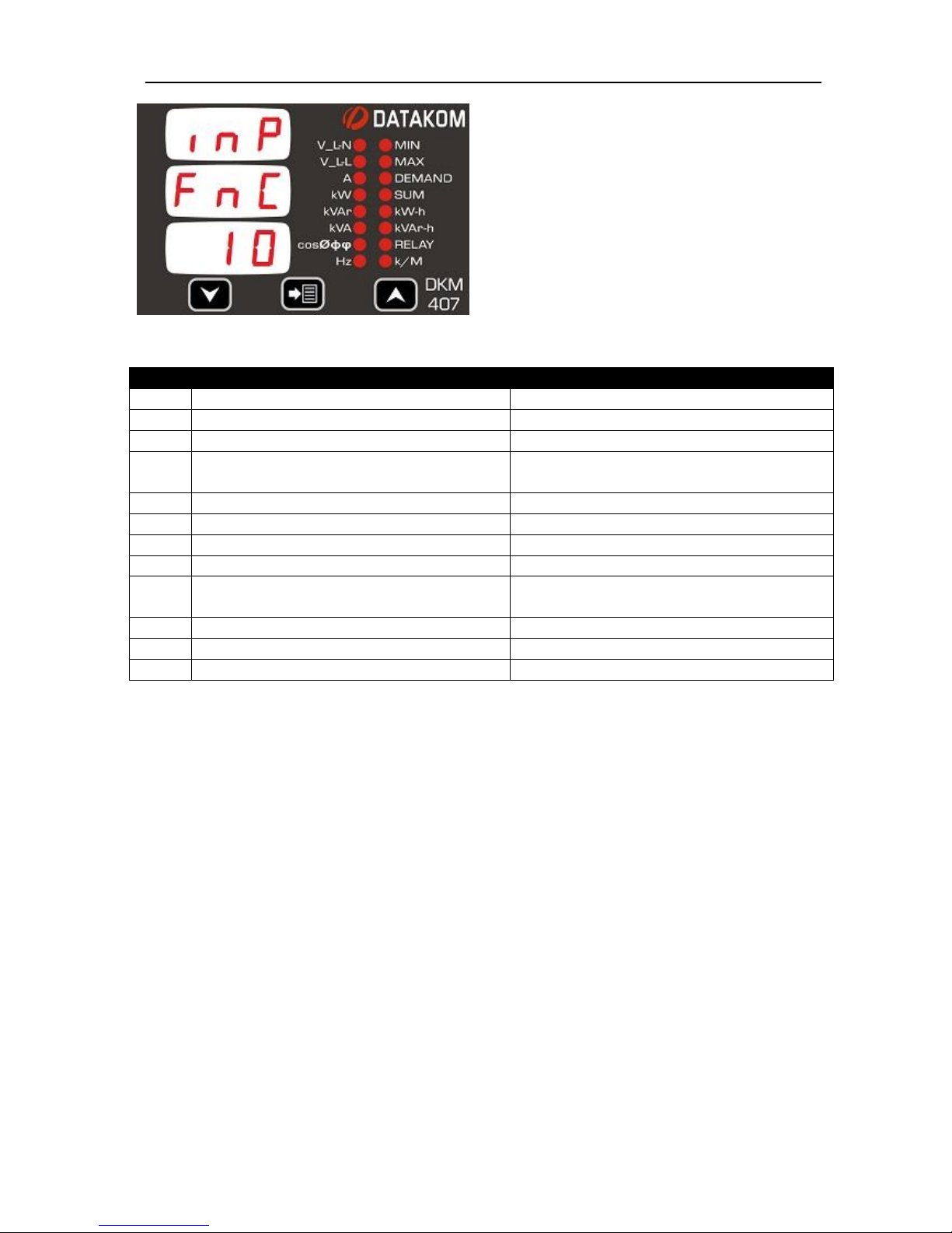
This parameter sets the function of the
digital input.
The factory set default value is 11.
Value
Function when signal active
Function when signal passive
0
kWh and kVArh counters increment
no increment
1
kWh and kVArh counters increment
kWh and kVArh counters reset to zero
2
kWh, kVArh, hour counters increment
no increment
3
kWh, kVArh, hour counters increment
kWh, kVArh and hour counters reset to
zero
4
Hour counter increment
no increment
5
Hour counter increment
Hour counter reset to zero
6
kWh and kVArh counters reset to zero
- 7 Hour counter reset to zero
-
8
kWh, kVArh and hour counters reset to
zero - 9
Reset alarms
-
10
Turn displays OFF
-
11
-
-
Page 21
DKM-407 Kullanım Kılavuzu V-1.1
21
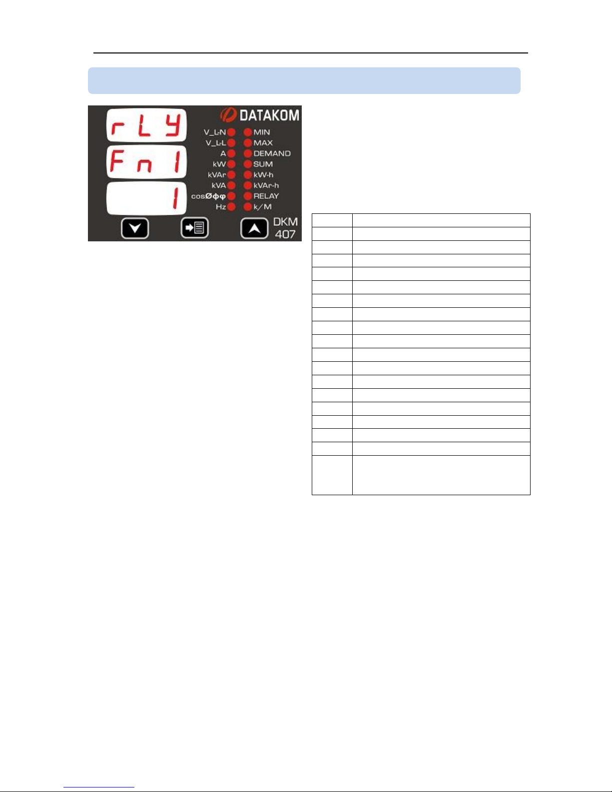
The relay output is a combination of 4
different input functions. The combination
logic is explained in the next picture.
Each of 4 available functions is selected
from the below list. Unused functions
should be left as 0.
Value
Relay Function
0 - 1
Follows the digital input
2
kWh pulse output
3
kVArh pulse output
4
High voltage alarm
5
Low voltage alarm
6
High frequency alarm
7
Low frequency alarm
8
Overcurrent alarm
9
Excess active power alarm
10
Low active power alarm
11
Excess reactive power alarm
12
Low reactive power alarm
13
High cosø alarm
14
Low cosø alarm
15
Phase sequence alarm
16
Relay active if any alarm exists
17
Function active if a non-zero
value is written to the Modbus
register 31.
The factory set value for relay function 1 is
1. For relay functions 2-3-4 it is 0.
4.16 CONFIGURING THE RELAY OUTPUT
Page 22
DKM-407 Kullanım Kılavuzu V-1.1
22
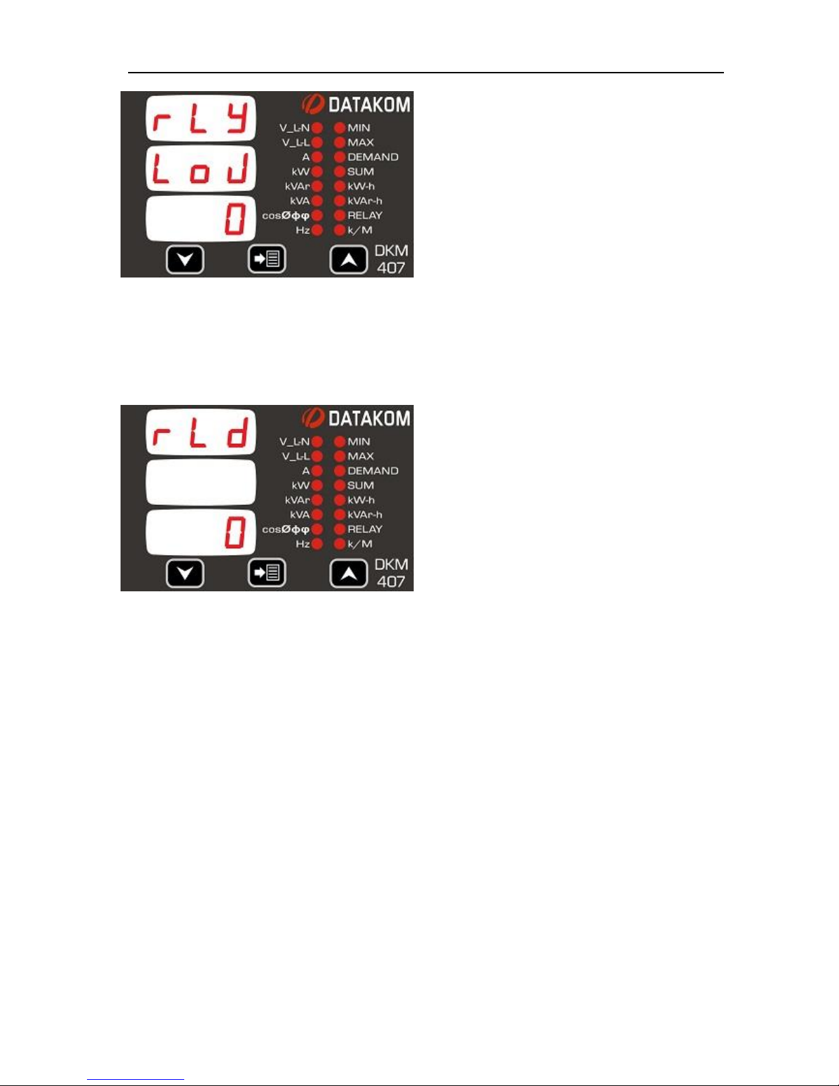
The relay output is the combination of 4
functions defined above. Thus various
combined functions may be attributed to
the relay output.
This parameter defines how functions are
combined in order to generate the relay
output.
0: Functions logically OR’ed. The relay
output is active if any of the 4 functions is
active.
1: Functions loagically AND’ed. The relay
output is active if all 4 functions are active.
This parameter defines the delay between
all conditions are met and the relay
operates. (in seconds)
Factory set value is 0.
Adjustment range is 0 to 9999 sec.
Page 23
DKM-407 Kullanım Kılavuzu V-1.1
23
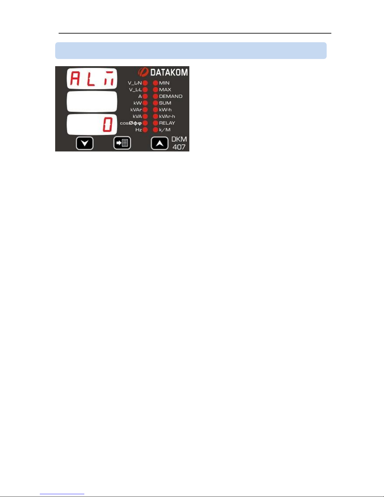
This parameter defines the delay between
an alarm condition occurs and the device
gives the alarm. It defines also the delay
between an alarm condition is removed and
the alarm goes off.
Factory set value is 0.
Adjustment range is 0 to 9999 sec.
4.17 ALARM DELAY
Page 24
DKM-407 Kullanım Kılavuzu V-1.1
24
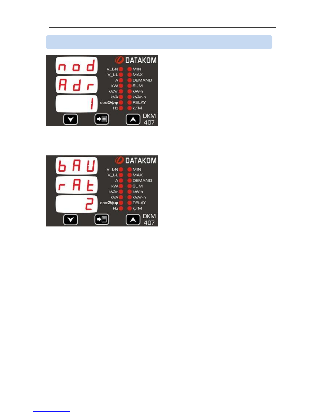
This is the Modbus node address of the
device. Each device in a Modbus network
must have a different node address.
Factory set value is 0.
Adjustment range is 0 to 255.
This parameter defines the bit rate used in
Modbus communication.
0: Baud rate = 2400
1: Baud rate = 4800
2: Baud rate = 9600
3: Baud rate = 19200
4: Baud rate = 38400
5: Baud rate = 57600
6: Baud rate = 115200
Factory set value is 2.
Adjustment range is 0 to 6.
.
4.18 MODBUS PARAMETERS
Page 25
DKM-407 Kullanım Kılavuzu V-1.1
25
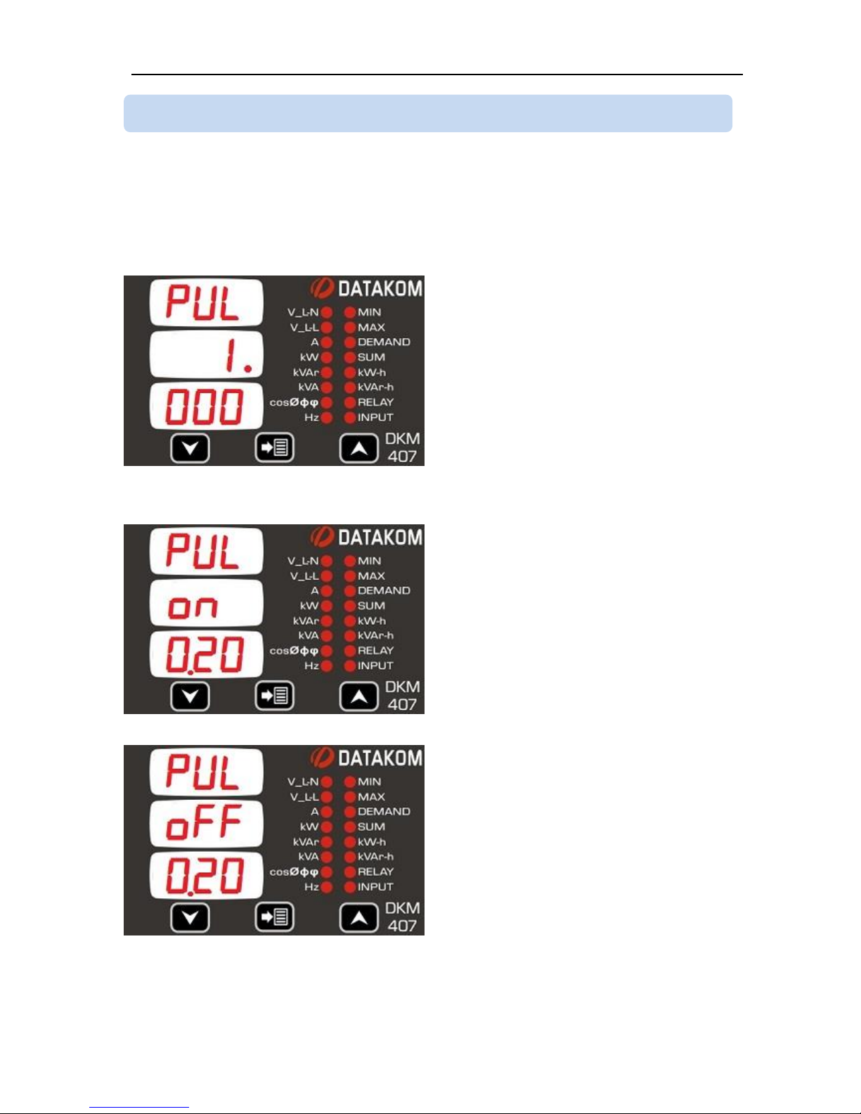
If any of the 4 relay functions explained in chapter 4.16 is set to 2 (kWh pulse) or 3 (kVArh
pulse) then the relay output will provide energy increment pulses conformally to below
settings. When pulse output is set, other 3 relay functions are “don’t care”. The relay will
function as a pulse output. kWh pulse output has priority. Thus if the output is set for both
kWh and kVArh then it will function as kWh.
This parameter determines the amount of
kWh (or kVArh) for 1 pulse output.
The factory set value is 1.000 kW per
pulse.
The adjustment range is from 0.001 to
10.000 kW (or kVArh)
Standart fabrika çıkış değeri 1.000 kWh
veya kVArh’dır.
.
This parameter determines the pulse active
period.
The factory set value is 0.20 sec (200
milisecond).
Adjustment range is 0.01sec to 9.99 sec.
This parameter determines the minimum
rest duration between two pulses.
The factory set value is 0.20 sec (200
milisecond).
Adjustment range is 0.01sec to 9.99 sec.
4.19 ENERGY PULSE OUTPUT (kWh, kVArh) PARAMETERS
Page 26
DKM-407 Kullanım Kılavuzu V-1.1
26
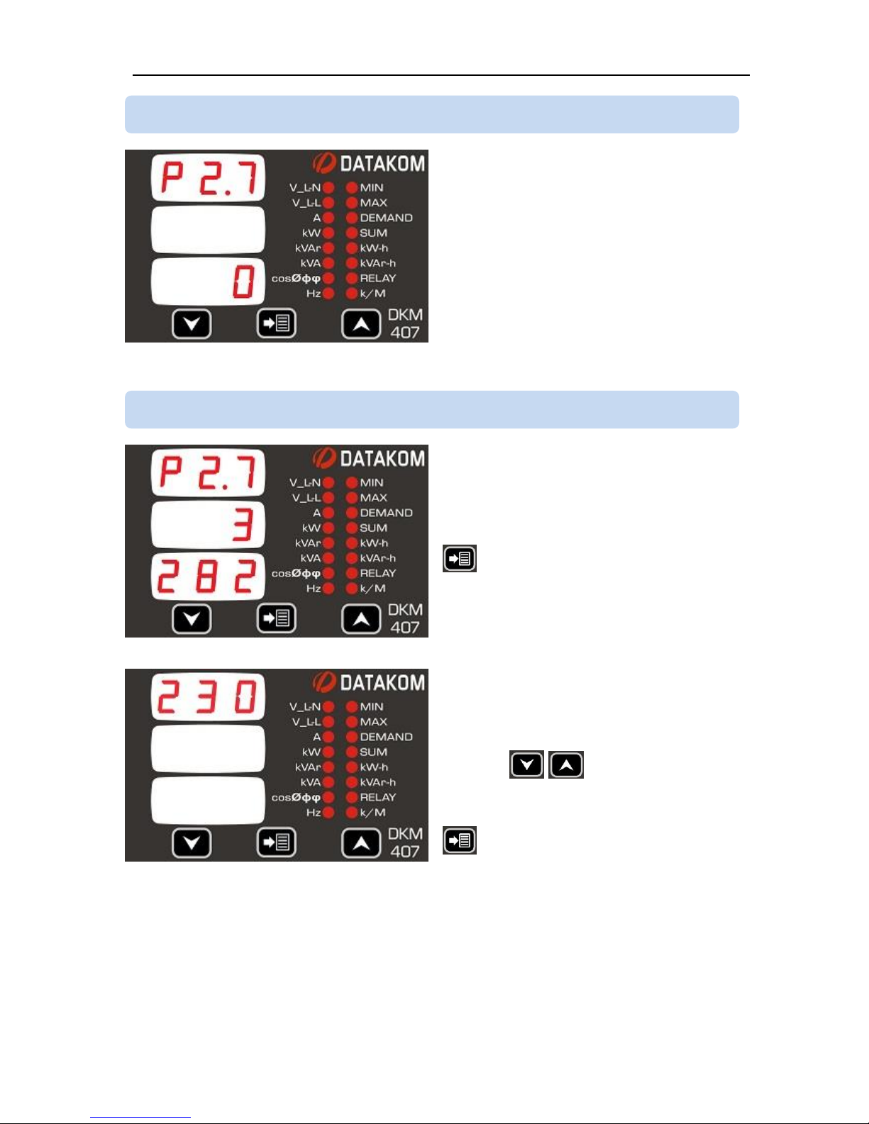
The device firmware version is displayed as
shown in the lefthand figure.
P2.7 indicates that the firmware version is
2.7.
The firmware version will be required by the
manufacturer together with any technical
support request.
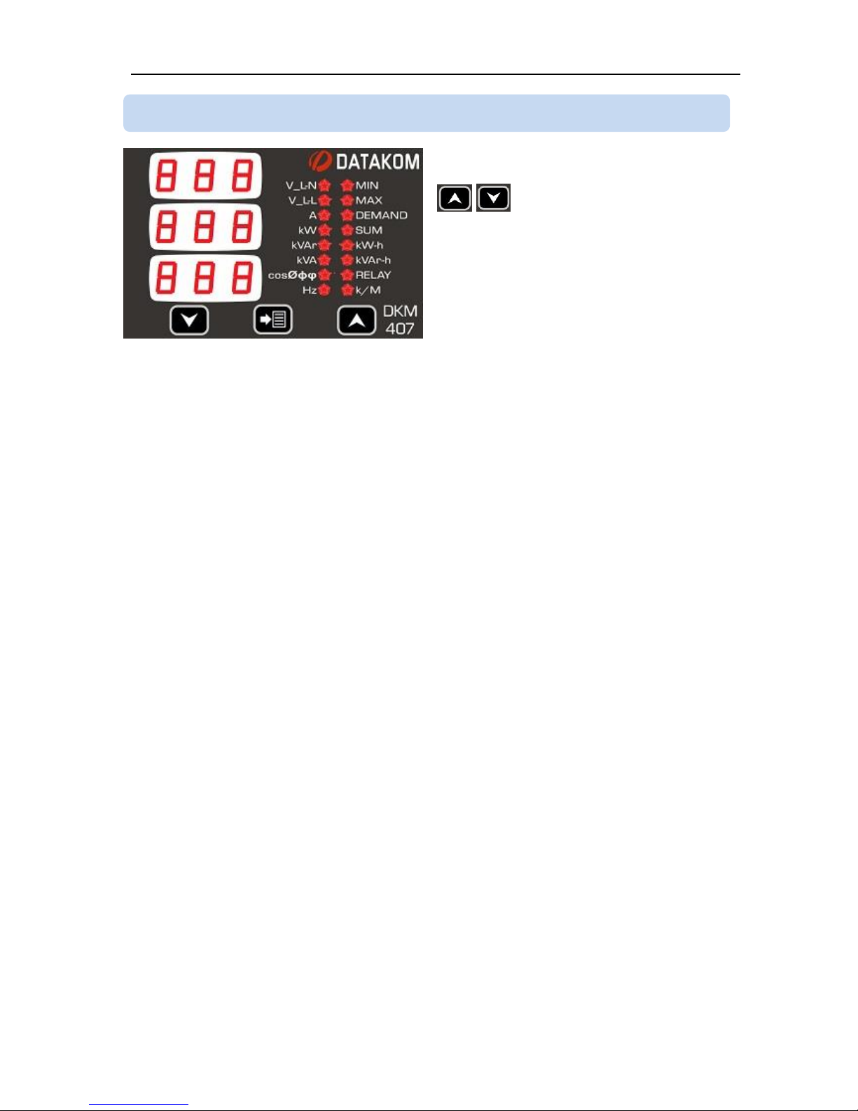
The unit is factory calibrated before
shipment.
If recalibration is required, Please enter
“3282” at the bottom display then press
button.
The calibration screen for L1 phase voltage
will appear. 1 second after, the coefficient
used for measuring the voltage will appear
in displays 2 and 3.
Pressing buttons will
increase/decrease the measured value.
When the measured value is correct press
button. The next input will come to
display.
Repeat above procedure for each input to
be recalibrated.
4.21 CALIBRATION
4.20 DISPLAYING THE FIRMWARE VERSION
Page 27
DKM-407 Kullanım Kılavuzu V-1.1
27
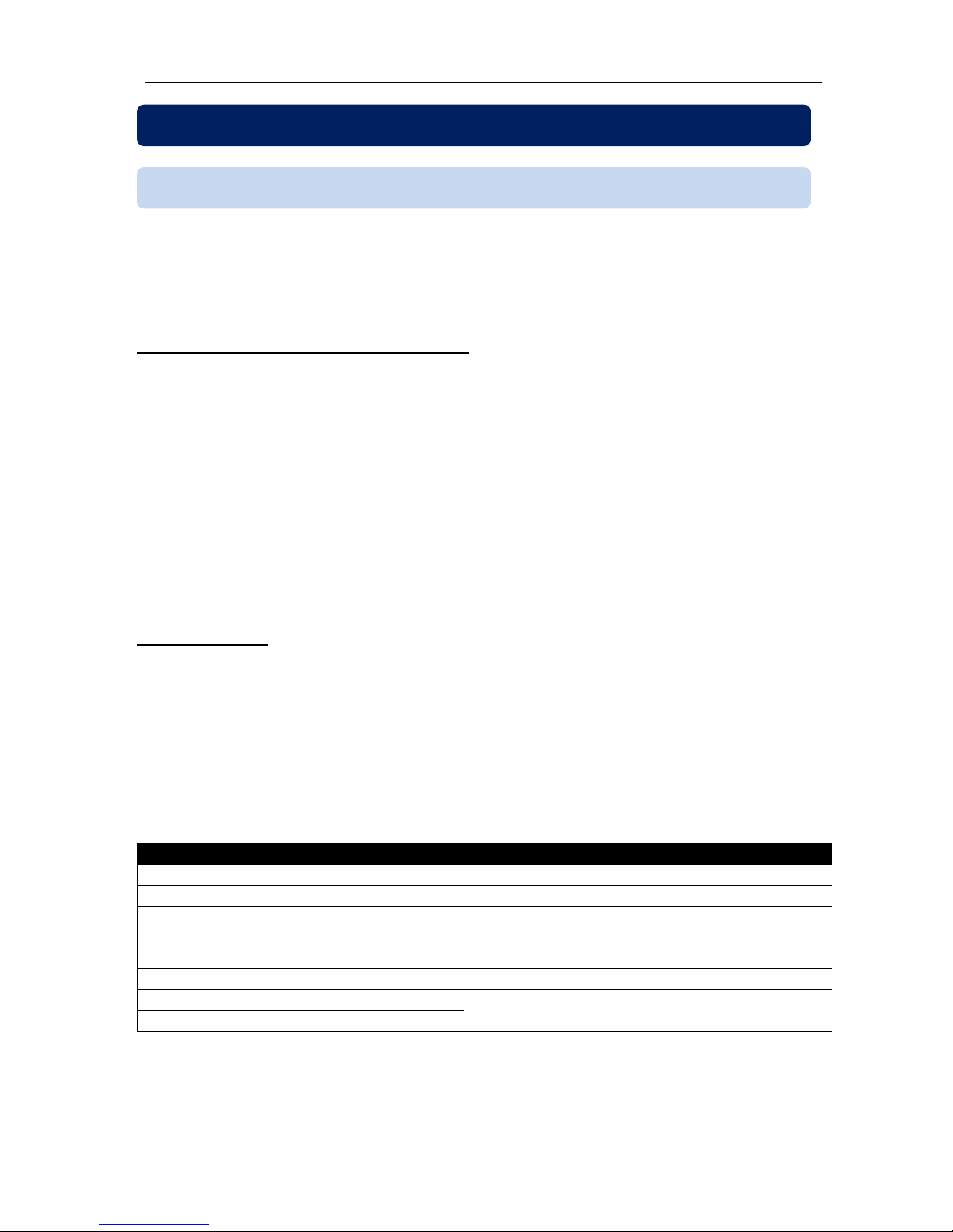
When all required parameters are
programmed hold pressed together both
buttons for 2 seconds.
This will exit the configuration menu and
perform a display test.
Check that all displays and leds are turned
on.
Press any button to exit LAMP TEST and
return to normal operating mode.
4.22 LAMP TEST
Page 28
DKM-407 Kullanım Kılavuzu V-1.1
28
The unit offers serial data communication port allowing it to be integrated in automation
systems.
The serial port is of RS-485 MODBUS-RTU standard. It is fully isolated from power supply
and measurement terminals for failure-free operation under harsh industrial conditions.
The MODBUS properties of the unit are:
-Data transfer mode: RTU
-Serial data: 1200-115200 bps adjustable, 8 bit data, no parity, 1 bit stop
-Supported functions:
-Function 3 (Read multiple registers)
-Function 6 (Write single register)
-Function 10h (Write multiple registers)
-The answer to an incoming message is sent with a minimum of 4.3ms delay after
message reception.
Each register consists of 2 bytes (16 bits). Larger data structures contain multiple registers.
Detailed description about the MODBUS protocol is found in the document “Modicon
Modbus Protocol Reference Guide”. This document may be downloaded at:
http://www.modbus.org/specs.php
Data Reading
The function 03 (read multiple registers) will be used for data reading. The MODBUS
master will send a query. The answer will be one of the below:
-A response containing the requested data
-An exceptional response indicating a read error.
The maximum number of registers read in one message is 123. If more registers are
requested, the unit will send only the first 123 registers.
The query message specifies the starting register and quantity of registers to be read. The
message structure is below:
Byte
Description
Value
0
Controller address
1 to 254
1
Function code
3 2 Starting address high
See below the description of available
registers
3
Starting address low
4
Number of registers high
always 0
5
Number of registers low
max 7Bh (123 decimal)
6
CRC low byte
See below for the checksum calculation
7
CRC high byte
Here is the sequence to read 16 registers starting from address 20h (32 decimal):
01 03 00 20 00 10 45 CC (each byte is expressed as 2 hexadecimal characters)
The checksum value in the above message may be used for the verification of checksum
calculation algorithm.
5. MODBUS COMMUNICATIONS
5.1. DESCRIPTION
Page 29
DKM-407 Kullanım Kılavuzu V-1.1
29
The normal response will be:
Byte
Description
Value
0
Controller address
same as in the query
1
Function code
3 2 Data lenght in bytes (L)
number of registers * 2
3
High byte of 1st register
4 Low byte of 1st register
5 High byte of 2nd register
6 Low byte of 2nd register
....
L+1
High byte of the last register
L+2
Low byte of the last register
L+3
CRC low byte
See below for the checksum calculation
L+4
CRC high byte
The exceptional response will be:
Byte
Description
Value
0
Controller address
same as in the query
1
Function code
131 (function code + 128)
2
Exception code
2 (illegal address)
3
CRC low byte
See below for the checksum calculation
4
CRC high byte
Data Writing
The function 06 (write single register) function 10h (write multiple registers) are used for
data writing. A maximum of 32 registers can be written at a time.
The MODBUS master will send a query containing data to be written. The answer will be
one of the below:
-A normal response confirming successful write,
-An exceptional response indicating a write error.
Only some of the available registers are authorized to be written. An attempt to write a write
protected register will result to the exceptional response.
The query message specifies the register address and data. The message structure is
below:
Byte
Description
Value
0
Controller address
1 to 254
1
Function code
6 2 Register address high
See below the description of available registers
3
Register address low
4
Data high byte
5
Data low byte
6
CRC low byte
See below for the checksum calculation
7
CRC high byte
Page 30
DKM-407 Kullanım Kılavuzu V-1.1
30
Here is the sequence to write the value 0010h to the register 40h (64 decimal):
01 06 00 40 00 10 89 D2 (each byte is expressed as 2 hexadecimal characters)
The checksum value in the above message may be used for the verification of checksum
calculation algorithm
The normal response will be the same as the query:
Byte
Description
Value
0
Controller address
1 to 253
1
Function code
6 2 Register address high
See below the description of available registers
3
Register address low
4
Data high byte
5
Data low byte
6
CRC low byte
See below for the checksum calculation
7
CRC high byte
The exceptional response will be:
Byte
Description
Value
0
Controller address
same as in the query
1
Function code
134 (function code + 128)
2
Exception code
2 (illegal address)
or
10 (write protection)
3
CRC low byte
See below for the checksum calculation
4
CRC high byte
CRC calculation
Here is a procedure for generating a CRC:
1) Load a 16–bit register with FFFF hex (all 1’s). Call this the CRC register.
2) Exclusive OR the first 8–bit byte of the message (the function code byte) with the low–
order byte of the 16–bit CRC register, putting the result in the CRC register.
3) Shift the CRC register one bit to the right (toward the LSB), zero–filling the MSB. Extract
and examine the LSB. The LSB is the least significant bit of the CRC before the shift
operation.
4) If the LSB is 1: Exclusive OR the CRC register with the polynomial value A001 hex.
5) Repeat Steps 3 and 4 until 8 shifts have been performed. Thus, a complete 8–bit byte
will be processed.
6) Repeat Steps 2 through 5 for the next 8–bit byte of the message. Continue doing this
until all bytes have been processed.
7) The final contents of the CRC register is the CRC value.
8) Place the CRC into the message such that the low byte is transmitted first. The algorithm
should give the correct CRC for below messages:
01 03 00 20 00 10 45 CC
01 06 00 40 00 10 89 D2
Page 31
DKM-407 Kullanım Kılavuzu V-1.1
31
Error codes
Only 3 error codes are used:
01: illegal function code
02: illegal address
10: write protection (attempt to write a read_only register)
Data types
Each register consists of 16 bits (2 bytes)
If the data type is a byte, only the low byte will contain valid data. High byte is don’t care.
For data type longer than 16 bits, consecutive registers are used. The least significant
register comes first.
Commands to the device are given by writing to below addresses.
If the value of “3282” is written to the address 16384, then below commands will be
accepted during 10 minutes.
Other commands do not require a password to be written.
ADRESS
NAME
DESCRIPTION
LENGTH
RD/
WR
DATA TYPE
COEF
16384
Password
Programming password
16 BIT
W-O
unsigned word
1
16385
Demand reset
Reset all demand registers
16 BIT
W-O
unsigned word
1
16386
Counter reset
Reset all energy counters
(kWh-kVArh)
16 BIT
W-O
unsigned word
1
16387
Hours reset
Reset hours counter
16 BIT
W-O
unsigned word
1
16388
Alarm reset
Reset all alarms
16 BIT
W-O
unsigned word
1
16389
Factory reset
Return to factory set values
16 BIT
W-O
unsigned word
1
5.2. COMMANDS
Page 32
DKM-407 Kullanım Kılavuzu V-1.1
32
ADRESS
NAME
DESCRIPTION
LENGTH
RD/
WR
DATA TYPE
COEF
01
Default screen
See chapter 4.6.
16 BIT
R/W
unsigned word
1
02
CT ratio
See chapter 4.7.
16 BIT
R/W
unsigned word
1
03
VT ratio
See chapter 4.8.
16 BIT
R/W
unsigned word
1
04
High voltage limit
See chapter 4.9.
16 BIT
R/W
unsigned word
1
05
Low voltage limit
See chapter 4.9.
16 BIT
R/W
unsigned word
1
06
High freq. limit
See chapter 4.10.
16 BIT
R/W
unsigned word
1
07
Low freq. limit
See chapter 4.10.
16 BIT
R/W
unsigned word
1
08
Overcurrent limit
See chapter 4.11.
16 BIT
R/W
unsigned word
1
09
High kW limit
See chapter 4.12.
16 BIT
R/W
unsigned word
1
10
Low kW limit
See chapter 4.12.
16 BIT
R/W
unsigned word
1
11
High kVAr limit
See chapter 4.13.
16 BIT
R/W
unsigned word
1
12
Low kVAr limit
See chapter 4.13.
16 BIT
R/W
unsigned word
1
13
High cos limit
See chapter 4.14.
16 BIT
R/W
unsigned word
1
14
Low cos limit
See chapter 4.14.
16 BIT
R/W
unsigned word
1
15
Digital input type
See chapter 4.15.
16 BIT
R/W
unsigned word
1
16
Digital input
detection delay
See chapter 4.15.
16 BIT
R/W
unsigned word
1
17
Digital input
function
See chapter 4.15.
16 BIT
R/W
unsigned word
1
18
Relay function 1
See chapter 4.16.
16 BIT
R/W
unsigned word
1
19
Relay function 2
See chapter 4.16.
16 BIT
R/W
unsigned word
1
20
Relay function 3
See chapter 4.16.
16 BIT
R/W
unsigned word
1
21
Relay function 4
See chapter 4.16.
16 BIT
R/W
unsigned word
1
22
Relay logic
See chapter 4.16.
16 BIT
R/W
unsigned word
1
23
Relay delay
See chapter 4.16.
16 BIT
R/W
unsigned word
1
24
Alarm delay
See chapter 4.17.
16 BIT
R/W
unsigned word
1
25
- - 16 BIT - -
-
26
Modbus node
address
See chapter 4.18.
16 BIT
R/W
unsigned word
1
27
Modbus baud
rate
See chapter 4.18.
16 BIT
R/W
unsigned word
1
28
Amount of kWh
(or kVArh) per
pulse
Explained in chapter 4.19.
16 BIT
R/W
unsigned word
0.001
29
Active pulse
duration (second)
Explained in chapter 4.19.
16 BIT
R/W
unsigned word
0.01
30
Rest between
pulses
Explained in chapter 4.19.
16 BIT
R/W
unsigned word
0.01
31
Relay control
through Modbus
If relay function is selected as
17 (see chapter 4.16) then if a
value other than zero is
written to this address then
the relay will operate.
16 BIT
R/W
unsigned word
1
5.3. PROGRAM PARAMETERS
Page 33
DKM-407 Kullanım Kılavuzu V-1.1
33
ADRESS
NAME
DESCRIPTION
LENGTH
RD/
WR
DATA TYPE
COEF
20480
Phase L1 voltage
32 BIT
R-O
unsigned long
1
20482
Phase L2 voltage
32 BIT
R-O
unsigned long
1
20484
Phase L3 voltage
32 BIT
R-O
unsigned long
1
20486
Phase L1-L2 voltage
32 BIT
R-O
unsigned long
1
20488
Phase L2-L3 voltage
32 BIT
R-O
unsigned long
1
20490
Phase L3-L1 voltage
32 BIT
R-O
unsigned long
1
20492
Phase L1 current
32 BIT
R-O
unsigned long
0.1
20494
Phase L2 current
32 BIT
R-O
unsigned long
0.1
20496
Phase L3 current
32 BIT
R-O
unsigned long
0.1
20498
Neutral current
RMS value of the
neutral current
32 BIT
R-O
unsigned long
0.1
20500
Phase L1 active power
32 BIT
R-O
unsigned long
0.1
20502
Phase L2 active power
32 BIT
R-O
unsigned long
0.1
20504
Phase L3 active power
32 BIT
R-O
unsigned long
0.1
20506
Total active power
32 BIT
R-O
unsigned long
0.1
20508
Phase L1 reactive power
32 BIT
R-O
unsigned long
0.1
20510
Phase L2 reactive power
32 BIT
R-O
unsigned long
0.1
20512
Phase L3 reactive power
32 BIT
R-O
unsigned long
0.1
20514
Total reactive power
32 BIT
R-O
unsigned long
0.1
20516
Phase L1 apparent power
32 BIT
R-O
unsigned long
0.1
20518
Phase L2 apparent power
32 BIT
R-O
unsigned long
0.1
20520
Phase L3 apparent power
32 BIT
R-O
unsigned long
0.1
20522
Total apparent power
32 BIT
R-O
unsigned long
0.1
20524
Phase L1 power factor
16 BIT
R-O
unsigned word
0.001
20525
Phase L2 power factor
16 BIT
R-O
unsigned word
0.001
20526
Phase L3 power factor
16 BIT
R-O
unsigned word
0.001
20527
Total power factor
16 BIT
R-O
unsigned word
0.001
20528
Frequency
16 BIT
R-O
unsigned word
0.01
20529
Phase L1 voltage THD
16 BIT
R-O
unsigned word
1
20530
Phase L2 voltage THD
16 BIT
R-O
unsigned word
1
20531
Phase L3 voltage THD
16 BIT
R-O
unsigned word
1
20532
Phase L1-L2 voltage THD
16 BIT
R-O
unsigned word
1
20533
Phase L2-L3 voltage THD
16 BIT
R-O
unsigned word
1
20534
Phase L3-L1 voltage THD
16 BIT
R-O
unsigned word
1
20535
Phase L1 current THD
16 BIT
R-O
unsigned word
1
20536
Phase L2 current THD
16 BIT
R-O
unsigned word
1
20537
Phase L3 current THD
16 BIT
R-O
unsigned word
1
20538
Neutral current THD
16 BIT
R-O
unsigned word
1
5.4. MEASUREMENTS AND CONTROLLER RECORDS
Page 34

DKM-407 Kullanım Kılavuzu V-1.1
34
ADRESS
NAME
DESCRIPTION
LENGTH
RD/
WR
DATA TYPE
COEF
20540
Phase L1 voltage MIN
32 BIT
R-O
signed long
1
20542
Phase L2 voltage MIN
32 BIT
R-O
signed long
1
20544
Phase L3 voltage MIN
32 BIT
R-O
signed long
1
20546
Phase L1-L2 voltage MIN
32 BIT
R-O
signed long
1
20548
Phase L2-L3 voltage MIN
32 BIT
R-O
signed long
1
20550
Phase L3-L1 voltage MIN
32 BIT
R-O
signed long
1
20552
Phase L1 current MIN
32 BIT
R-O
signed long
0.1
20554
Phase L2 current MIN
32 BIT
R-O
signed long
0.1
20556
Phase L3 current MIN
32 BIT
R-O
signed long
0.1
20558
Neutral current MIN
32 BIT
R-O
signed long
0.1
20560
Phase L1 active power MIN
32 BIT
R-O
signed long
0.1
20562
Phase L2 active power MIN
32 BIT
R-O
signed long
0.1
20564
Phase L3 active power MIN
32 BIT
R-O
signed long
0.1
20566
Total active power MIN
32 BIT
R-O
signed long
0.1
20568
Phase L1 reactive power MIN
32 BIT
R-O
signed long
0.1
20570
Phase L2 reactive power MIN
32 BIT
R-O
signed long
0.1
20572
Phase L3 reactive power MIN
32 BIT
R-O
signed long
0.1
20574
Total reactive power MIN
32 BIT
R-O
signed long
0.1
20576
Phase L1 apparent power MIN
32 BIT
R-O
signed long
0.1
20578
Phase L2 apparent power MIN
32 BIT
R-O
signed long
0.1
20580
Phase L3 apparent power MIN
32 BIT
R-O
signed long
0.1
20582
Total apparent power MIN
32 BIT
R-O
signed long
0.1
20584
Phase L1 power factor MIN
32 BIT
R-O
signed long
0.001
20586
Phase L2 power factor MIN
32 BIT
R-O
signed long
0.001
20588
Phase L3 power factor MIN
32 BIT
R-O
signed long
0.001
20590
Total power factor MIN
32 BIT
R-O
signed long
0.001
20592
Frequency MIN
32 BIT
R-O
signed long
0.01
Page 35

DKM-407 Kullanım Kılavuzu V-1.1
35
ADRESS
NAME
DESCRIPTION
LENGTH
RD/
WR
DATA TYPE
COEF
20594
Phase L1 voltage MAX
32 BIT
R-O
signed long
1
20596
Phase L2 voltage MAX
32 BIT
R-O
signed long
1
20598
Phase L3 voltage MAX
32 BIT
R-O
signed long
1
20600
Phase L1-L2 voltage MAX
32 BIT
R-O
signed long
1
20602
Phase L2-L3 voltage MAX
32 BIT
R-O
signed long
1
20604
Phase L3-L1 voltage MAX
32 BIT
R-O
signed long
1
20606
Phase L1 current MAX
32 BIT
R-O
signed long
0.1
20608
Phase L2 current MAX
32 BIT
R-O
signed long
0.1
20610
Phase L3 current MAX
32 BIT
R-O
signed long
0.1
20612
Neutral current MAX
32 BIT
R-O
signed long
0.1
20614
Phase L1 active power MAX
32 BIT
R-O
signed long
0.1
20616
Phase L2 active power MAX
32 BIT
R-O
signed long
0.1
20618
Phase L3 active power MAX
32 BIT
R-O
signed long
0.1
20620
Total active power MAX
32 BIT
R-O
signed long
0.1
20622
Phase L1 reactive power MAX
32 BIT
R-O
signed long
0.1
20624
Phase L2 reactive power MAX
32 BIT
R-O
signed long
0.1
20626
Phase L3 reactive power MAX
32 BIT
R-O
signed long
0.1
20628
Total reactive power MAX
32 BIT
R-O
signed long
0.1
20630
Phase L1 apparent power MAX
32 BIT
R-O
signed long
0.1
20632
Phase L2 apparent power MAX
32 BIT
R-O
signed long
0.1
20634
Phase L3 apparent power MAX
32 BIT
R-O
signed long
0.1
20636
Total apparent power MAX
32 BIT
R-O
signed long
0.1
20638
Phase L1 power factor MAX
32 BIT
R-O
signed long
0.001
20640
Phase L2 power factor MAX
32 BIT
R-O
signed long
0.001
20642
Phase L3 power factor MAX
32 BIT
R-O
signed long
0.001
20644
Total power factor MAX
32 BIT
R-O
signed long
0.001
20646
Frequency MAX
32 BIT
R-O
signed long
0.01
20648
kWh counter
32 BIT
R-O
unsigned long
0.1
20650
kVArh counter
32 BIT
R-O
unsigned long
0.1
20652
Total run hour counter
32 BIT
R-O
unsigned long
0.1
20654
LEDs
LED status
16 BIT
R-O
unsigned word
1
20655
Buttons
Buton status
16 BIT
R-O
unsigned word
1
20656
Alarms
Alarm status
16 BIT
R-O
unsigned word
1
20657
Relay Status
Relay is ON if
value is not
zero
16 BIT
R-O
unsigned word
1
20658
Voltage Demand
32 BIT
R-O
signed long
1
20660
Current Demand
32 BIT
R-O
signed long
0.1
20662
Active Power Demand
32 BIT
R-O
signed long
0.1
Page 36

DKM-407 Kullanım Kılavuzu V-1.1
36
LED status register is 16 bits long. Each bit shows the status of one led.
BIT NO:
DESCRIPTION
0
k/M (Kilo/Mega)
1
Relay
2
Frequency (Hz)
3
Total (Sum)
4
Demand
5
MAX
6
MIN
7
kVArh
8
kWh
9
cos
10
kVA
11
kVAr
12
kW
13
Amperes (A)
14
Phase-Phase Voltages (VLL)
15
Phase-Neutral Voltages (VLN)
Button status register is 16 bits long. Each bit shows the status of one button.
BIT NO:
DESCRIPTION
0
Set (Menu) button pressed
1
Set (Menu) button long pressed
2
Set (Menu) button very long pressed
3
Up Arrow button pressed
4
Up Arrow button long pressed
5
Up Arrow button very long pressed
6
Down Arrow button pressed
7
Down Arrow button long pressed
8
Down Arrow button very long pressed
9
Digital Input Status (1:N.O. 0:N.C.)
10 - 11 - 12
-
13 - 14 - 15
-
Page 37

DKM-407 Kullanım Kılavuzu V-1.1
37
Alarm status register is 16 bit long. Each bit shows tha status of an alarm.
BIT NO:
DESCRIPTION
0
-
1 - 2 - 3
-
4
High voltage
5
Low voltage
6
High Frequency
7
Low Frequency
8
High current
9
High kW
10
Low kW
11
High kVAr
12
Low kVAr
13
High power factor (cos)
14
Low power factor (cos)
15
Phase sequence failure
Page 38

DKM-407 Kullanım Kılavuzu V-1.1
38
Supply voltage: 85-305 V AC (L1-NEUTRAL)
Supply frequency: 45-65Hz
Measurement inputs:
Voltage: 10 - 305 V AC (P-N)
20 - 530 V AC (P-P)
Current: 0.2 - 6.00 A AC
Frequency: 30 - 100 Hz
Accuracy:
Voltage: % 0.5 + 1 digit
Current: % 0.5 + 1 digit
Frequency: % 0.5 + 1 digit
Power (kW,kVAr): %1.0 + 2 digit
Cos: %2.0 + 2 digit
Measurement range:
CT range: 5/5A to 5000/5A
VT range: 0.1/1 to 200.0/1
kW range: 0.1 kW to 6.5 MW
Power consumption: < 4 VA
Loading:
Voltage inputs: < 0.1VA per phase
Current inputs: < 1VA per phase
Relay output: 5A @ 250V AC
Digital input:
Active level: 5 - 30V DC or AC
Min pulse: 250ms.
Isolation: 1000V AC, 1 minute
Operating temp. range: -20°C to +70 °C
-4 °F to 158°F
Max. Relative humidity: 95% non condensing
Enclosure: Flame retardent, ROHS compliant, high temperature ABS/PC (UL94-V0)
Installation: DIN rail mounted
Dimensions: 70x115x66mm (WxHxD)
Weight: 200 g (approximative)
EU Directives:
2006/95/EC (LVD)
2004/108/EC
(EMC)
Reference
standards:
EN 61010 (safety)
EN 61326 (EMC)
DATAKOM Elektronik Ltd.
Tel: +90-216-466 84 60 Fax: +90-216-364 65 65 e-mail: [email protected] http: www.datakom.com.tr
6. TECHNICAL SPECIFICATIONS
 Loading...