

Page 1
DKM-250 User Manual V-2.0
DKM-250
DC ENERGY
ANALYZER
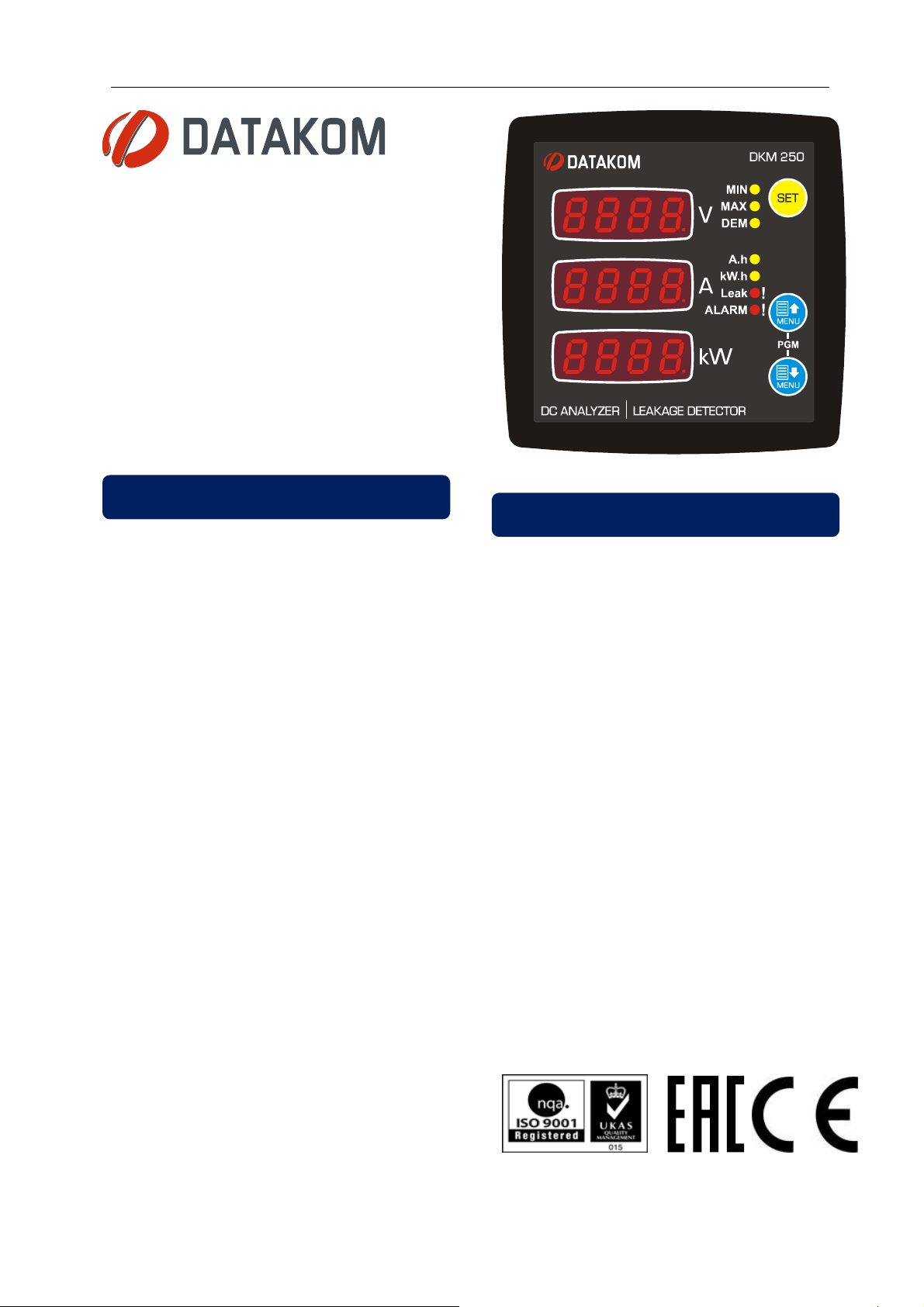
DESCRIPTION
The DKM-250 is a precision instrument
designed for measuring, displaying and
remote monitoring earth leakage and various
DC parameters in a DC distribution box.
The unit features a 32-bit ARM core
microcontroller.
The unit is supplied from the measuring DC
voltage input. Operating range is between 19
and 150VDC.
The current input of the unit is isolated from
the rest of the circuit and has different circuit
options:
● External current shunt (standard)
● Internal current shunt
● Hall Effect sensor input
● 4-20mA analog input
The unit has 2 digital inputs and 2 relay
outputs, both of them programmable for
required functions.
FEATURES
● Displays earth leakage in %
● Various current input options
● 2 programmable relay outputs
● 2 programmable digital inputs
● Programmable 4-20mA analog output
● Demand, Min & Max records
● Fully isolated RS-485 serial port
● MODBUS-RTU communications
● Bidirectional current & power measurement
● Bidirectional kW-h energy counter
● Bidirectional A-h counter
● Hours run counter
● Front panel programming
● Wide operating temperature range
Thanks to its isolated RS-485 Modbus RTU
comport, the device is free from ground
potential difference issues and data are
safely transferred to automation and
monitoring systems. Program parameters
may be uploaded to the unit through the RS485 port.
The unit may output any measured value as
analog signal through its 4-20mA port. This
output allows easy connection to PLC
systems.
● Sealed front panel (IP65 with gasket)
● Two part connection system
1
Page 2
DKM-250 User Manual V-2.0
Electrical equipment should be installed only by qualified
Check the unit for cracks and damages due to transportation.
Fuses must be connected to the power supply and voltage
Fuses must be of fast type
with a maximum rating of 6A.
Disconnect all power before working on equipment.
When the unit is connected to the networ
k do not touch
Any electrical parameter applied to the device must be in the
Verify correct terminal connections before applying power.
Only for
front
panel mounting.
SAFETY NOTICE
Failure to follow below instructions will result in
death or serious injury
specialist. No responsibility is assured by the manufacturer or
any of its subsidiaries for any consequences resulting from the
non-compliance to these instructions.
Do not install damaged equipment.
Do not open the unit. There are no serviceable parts inside.
inputs, in close proximity of the unit.
terminals.
range specified in the user manual. Although the unit is
designed with a wide safety margin, over-range parameters may
reduce lifetime, alter operational precision or even damage the
unit.
Do not try to clean the device with solvent or the like. Only
clean with a dump cloth.
2
Page 3

DKM-250 User Manual V-2.0
TABLE OF CONTENTS
Section
1. INSTALLATION INSTRUCTIONS
1.1 FRONT AND BACK PANELS
1.2 ELECTRICAL INSTALLATION
1.3 INSTALLATION DIAGRAM
2. PUSHBUTTON FUNCTIONS
3. SCREEN NAVIGATION
4. PROGRAMMING
4.1 ENTERING THE PROGRAMMING MODE
4.2 RESETTING DEMANDS
4.3 RESETTING ENERGY COUNTERS
4.4 RESETTING Ah (ampere*hour) COUNTERS
4.5 RESETTING RUN HOURS
4.6 RESETTING ALARMS
4.7 ADJUSTING CURRENT MEASUREMENT INPUT
4.8 ADJUSTING CURRENT HIGH LIMIT
4.9 ADJUSTING VOLTAGE LOW AND HIGH LIMITS
4.10 SELECTING VOLTAGE MEASUREMENT INPUT
4.11 ADJUSTING LOW AND HIGH POWER LIMITS
4.12 ADJUSTING THE DEMAND PERIOD
4.13 ADJUSTING THE 4-20mA ANALOG OUTPUT
4.14 SELECTING THE DEFAULT SCREEN
4.15 ALARM CONFIGURATION
4.16 MODBUS PARAMETERS
4.17 ADJUSTING LOW AND HIGH EARTH LEAKAGE LIMITS
4.18 PROGRAMMABLE RELAY SETUP
4.19 PROGRAMMABLE DIGITAL INPUT SETUP
4.20 OUTPUT PULSE (kWh, Ah, hour) SETUP
4.21 DISPLAYING THE FIRMWARE VERSION
4.22 CALIBRATION
4.23 LAMP TEST
5. MODBUS COMMUNICATIONS
5.1. DESCRIPTION
5.2. COMMANDS
5.3. PROGRAM PARAMETERS
5.4. MEASUREMENTS AND CONTROLLER RECORDS
6. TECHNICAL SPECIFICATIONS
3
Page 4
DKM-250 User Manual V-2.0
1. INSTALLATION INSTRUCTIONS
Before installation:
Read the user manual carefully, determine the correct connection diagram.
Remove all connectors and mounting brackets from the unit, then pass the unit through the mounting
opening.
Put mounting brackets and tighten. Do not tighten too much, this can damage the enclosure.
Make electrical connections with plugs removed from sockets, then place plugs to their sockets.
Be sure that adequate cooling is provided.
Be sure that the temperature of the environment will not exceed the maximum operating temperature in any
case.
Be sure that the unit is not subject to water spill.
Below conditions may damage the device:
Incorrect connections.
Incorrect power supply voltage.
Voltage at measuring terminals beyond specified range.
Current at measuring terminals beyond specified range.
Voltage applied to digital inputs over specified range.
Overloading or short-circuiting relay outputs
Connecting or removing data terminals when the unit is powered-up.
High voltage applied to communication ports.
Excessive vibration, direct installation on vibrating parts.
Current Shunt must be used for current measurement.
No direct connection allowed
.
Below conditions may cause abnormal operation:
Power supply voltage below minimum acceptable level.
4
Page 5
DKM-250 User Manual V-2.0
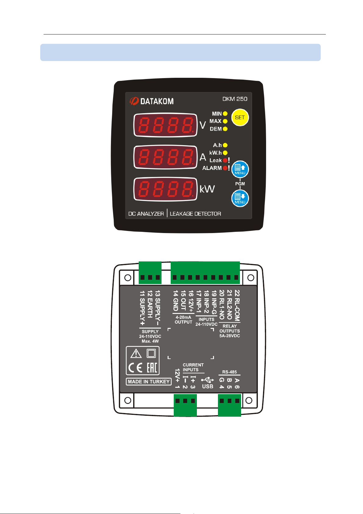
1.1 FRONT AND BACK PANELS
5
Page 6
DKM-250 User Manual V-2.0
1.2 ELECTRICAL INSTALLATION
Do not install the unit close to high electromagnetic
noise emitting devices like contactors, high current
busbars, switchmode power supplies and the like.
Although the unit is protected against electromagnetic disturbance, excessive disturbance
can affect the operation, measurement precision and data communication quality.
ALWAYS remove plug connectors when inserting wires with a screwdriver.
Fuses must be connected to the power supply and voltage inputs, in close proximity
of the unit.
Fuses must be of fast type with a maximum rating of 6A.
Use cables of appropriate temperature range.
Use adequate cable section, at least 0.75mm2 (AWG18).
Follow national rules for electrical installation.
Current Shunt must be used for current measurement.
No direct connection allowed
.
6
Page 7
DKM-250 User Manual V-2.0
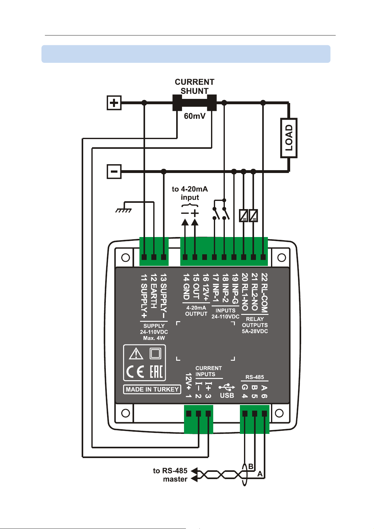
1.3 INSTALLATION DIAGRAM
7
Page 8
DKM-250 User Manual V-2.0
2. PUSHBUTTON FUNCTIONS
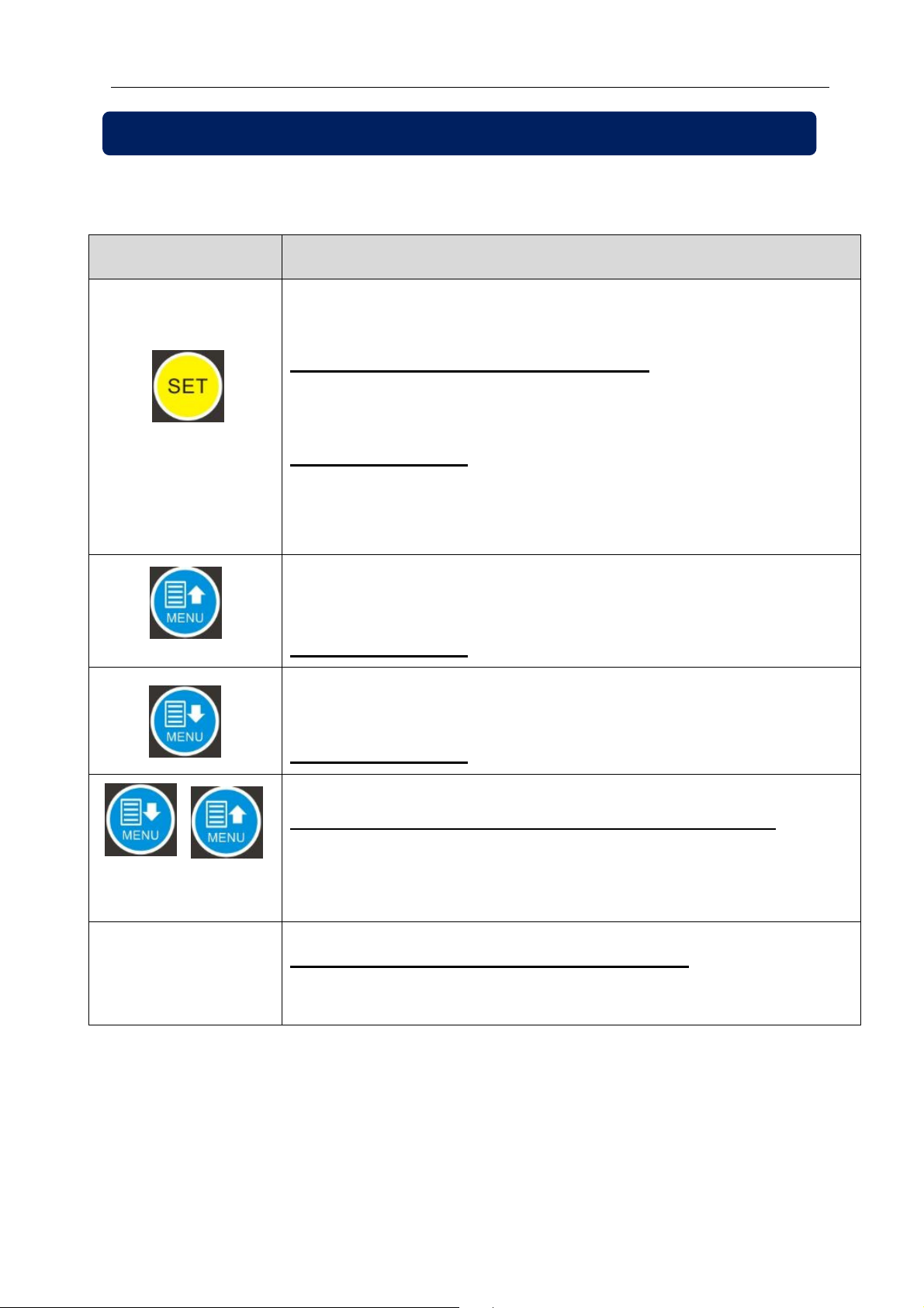
3 front panel buttons allow navigation between measurement and programming screens.
BUTTON
FUNCTION
If more than one active alarm exists, then display next
alarm.
HELD PRESSED FOR 2 SECONDS:
Resets Min-Max values and alarms and displays the
minimum values.
PROGRAMMING: Save adjusted parameter and switch
to the next parameter. If long-pressed then switch to
previous parameter.
Switch to the upper screen.
PROGRAMMING: increase value
Switch to the lower screen.
PROGRAMMING: decrease value
HELD PRESSED TOGETHER FOR 2 SECONDS:
Selects programming mode. If held pressed in
programming mode, then returns to normal mode.
NO KEY PRESSED DURING 1 MINUTE:
Returns to the selected main display screen.
8
Page 9
DKM-250 User Manual V-2.0
3. SCREEN NAVIGATION
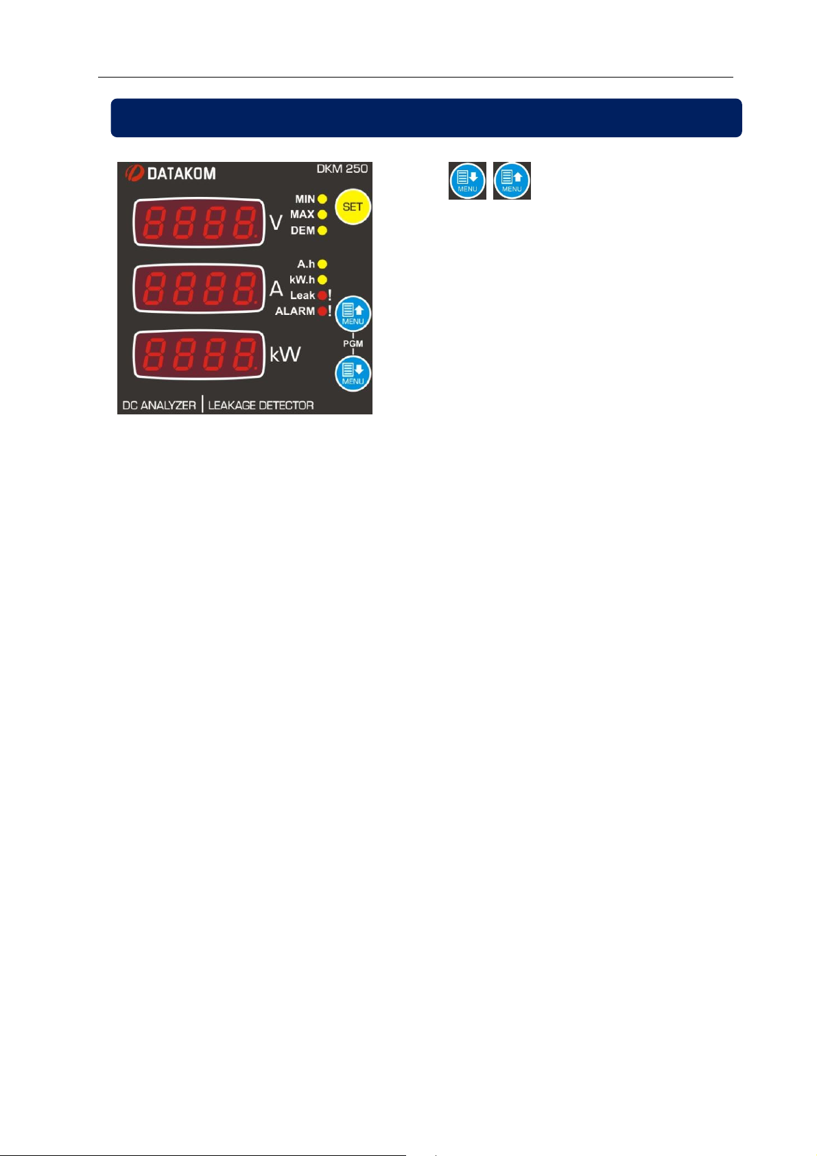
Buttons allow navigation
between measurement values. The yellow
led related to the currently displayed
values will turn on. As an exception, if the
total run hours is displayed, “Ah” and
“kWh” leds will turn on.
In the occurrence of an alarm the red
ALARM led turns on and the alarm is
displayed on the screen.
If positive or negative earth leakage
occurs, both LEAK and ALARM leds will
turn on.
If Ah and kWh leds are off, the upper screen shows the voltage (in volts), the mid-screen
shows the current (in amperes) and the lower screen shows the power (in kilowatts).
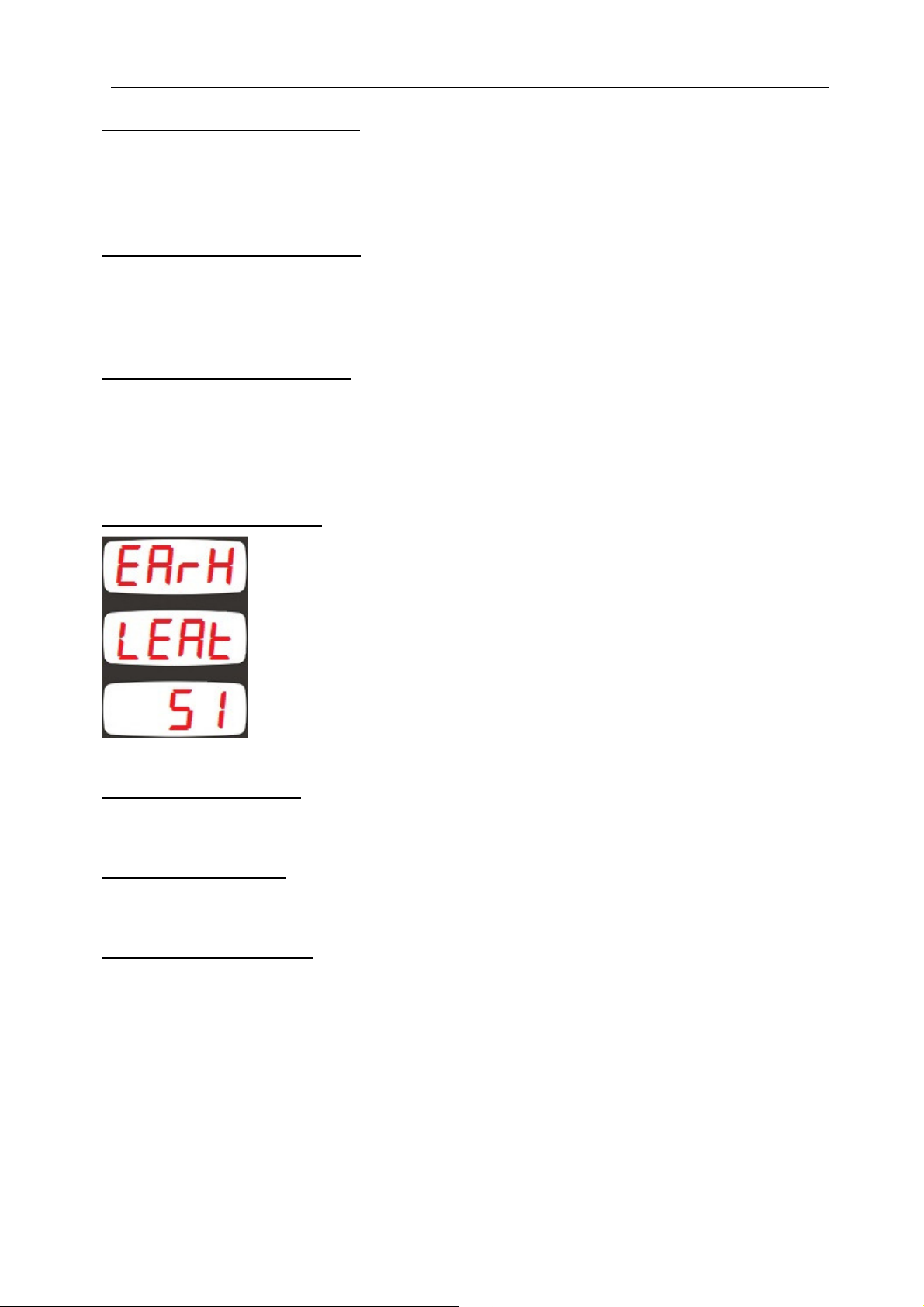
When no yellow led is on and the upper screen displays “EARH” and the middle screen
displays “LEAK”, then the lower display will show the earth leakage in percent (%).
If no led is on then these are instantaneous measured values. The “MIN” led denotes
minimum values, the “MAX” led denotes maximum values, the “DEM” led denotes demand
values. If MAX and DEM leds are both on, the display shows maximum demand values.
9
Page 10
DKM-250 User Manual V-2.0
Display of measured current: If the measured current value is below 100A, then it is
displayed with 0.01A precision. Between 100A and 1000A it is displayed with 0.1A
precision. Between 1000A and 10000A it is displayed with 1A precision. When read from
Modbus, the current will have 0.01A precision.
Display of measured voltage: If the measured voltage value is below 100V then it is
displayed with 0.01V precision. If the voltage is between 100V and 1000V it is displayed
with 0.1V precision. Between 1000V and 10000V the voltage is displayed with 1 V
precision. When read from Modbus, the voltage will have 0.01V precision.
Display of measured power: If the measured power is below 10kW then it is displayed
with 0.001kW precision. Between 10kW and 100kW it is displayed with 0.01kW precision.
Between 100kW and 1000kW it is displayed with 0.1kW precision. Between 1000kW and
10000kW it is displayed with 1kW precision. When read from Modbus, the power will have
0.001kW precision.
Display of earth leakage:
The measured earth leakage is displayed with 1%
precision from both Modbus and the screen.
kWh counters display: kWh (energy) counters are always read (from both Modbus and
screen) with 0.1kWh precision.
Ah counters display: Ah counters are always read (from both Modbus and screen) with
0.1Ah precision.
Total run hours display: Total run hours counters are always read (from both Modbus and
screen) with 0.1hour precision.
10
Page 11
DKM-250 User Manual V-2.0
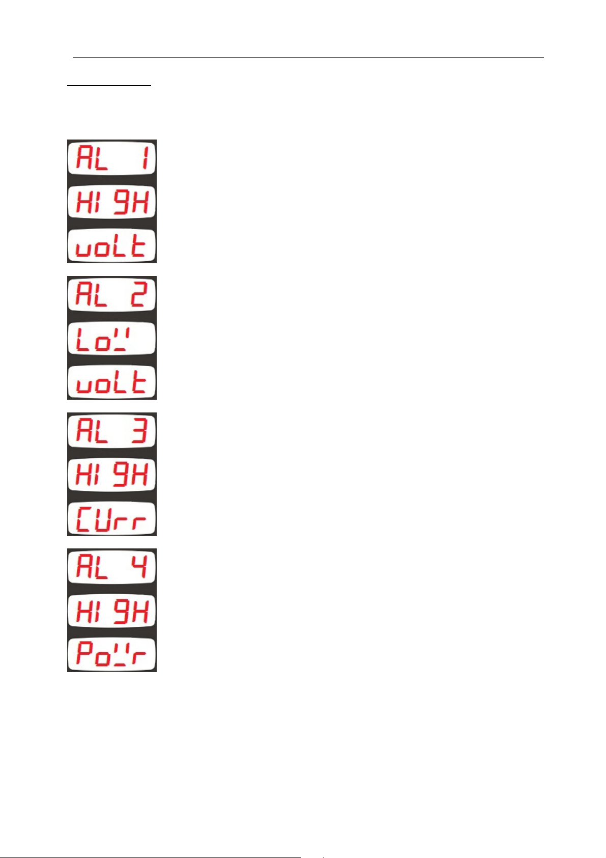
Alarm display: When an alarm occurs, then the ALARM led will turn on and the display will
show the alarm information every 2 seconds. If multiple alarms are present, other alarms
may be displayed by pressing the SET pushbutton.
Alarm 1 : High Voltage Alarm
Alarm 2 : Low Voltage Alarm
Alarm 3 : Excess Current Alarm
Alarm 4 : Excess Power (kW) Alarm
11
Page 12
DKM-250 User Manual V-2.0
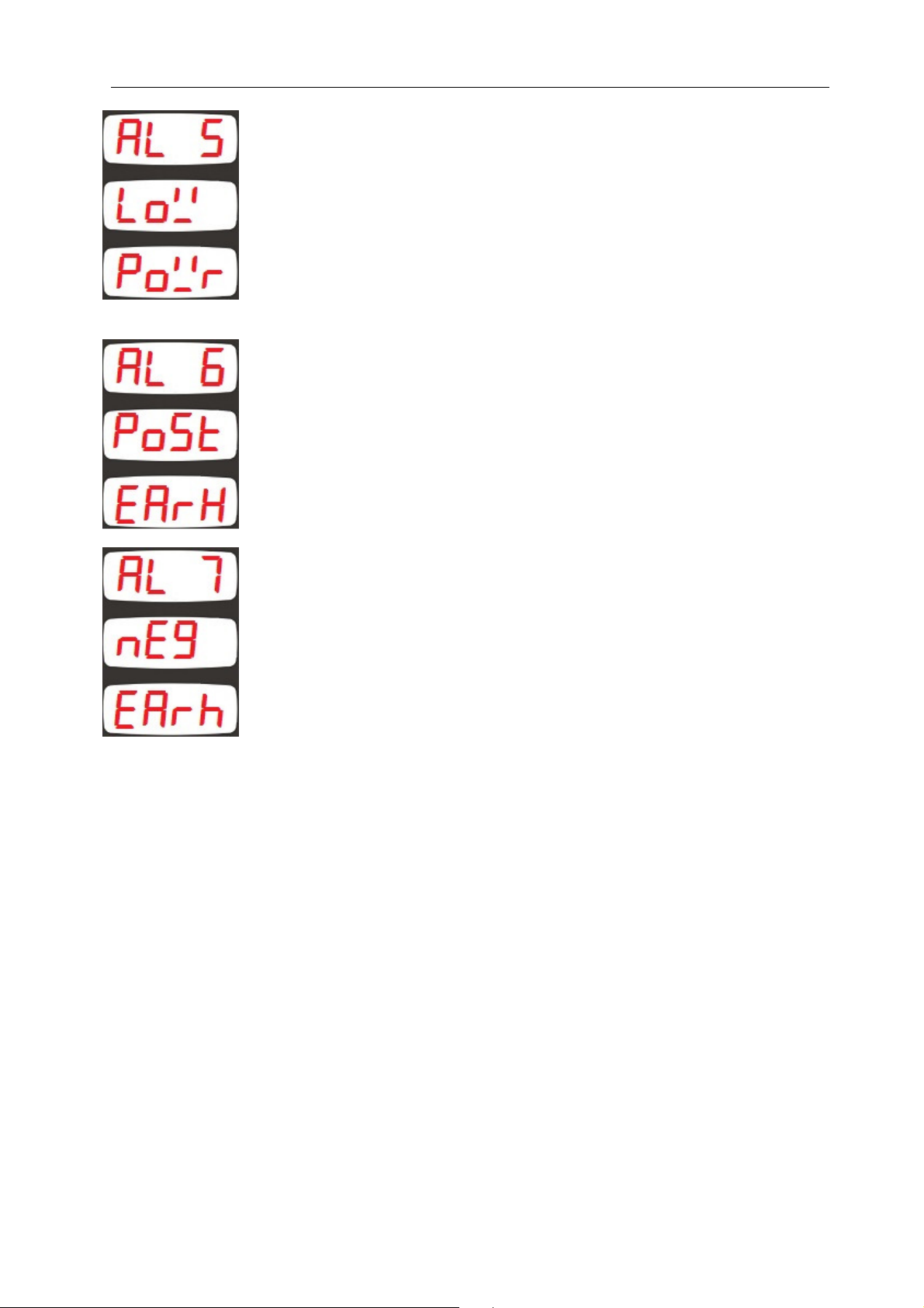
Alarm 5 : Low Power (kW) Alarm
Alarm 6 : Positive (+) earth leakage alarm
Alarm 7 : Negative (-) earth leakage alarm
12
Page 13
DKM-250 User Manual V-2.0
the unit
sed for 2 seconds, then
4. PROGRAMMING
4.1 ENTERING THE PROGRAMMING MODE
In order to offer the maximum flexibility to the customer, the module has several
programmable parameters.
Device configurations
Default screen configuration
Measurement configurations
Demand reset
Counter reset
Alarm reset
Current shunt configuration
Alarm high/low limit adjustments
Input/Output Configurations
Alarm configuration
Modbus Codbus configuration
Unit Calibration
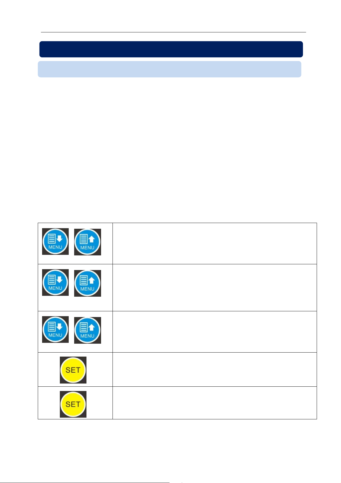
In order to enable the programming menu,
hold both MENU buttons pressed for 2 seconds.
In order to exit programming menu,
hold both MENU buttons pressed for 2 seconds.
If no button is pressed during 1 minute, then
will automatically close the programming mode.
Parameter values are modified with UP and DOWN
Menu buttons. If the button is held pressed, the the
value will change with larger steps.
When SET button is pressed, the value on the
screen is recorded and the next parameter is
displayed.
If the SET button is held pres
the previous parameter is displayed.
13
Page 14
DKM-250 User Manual V-2.0
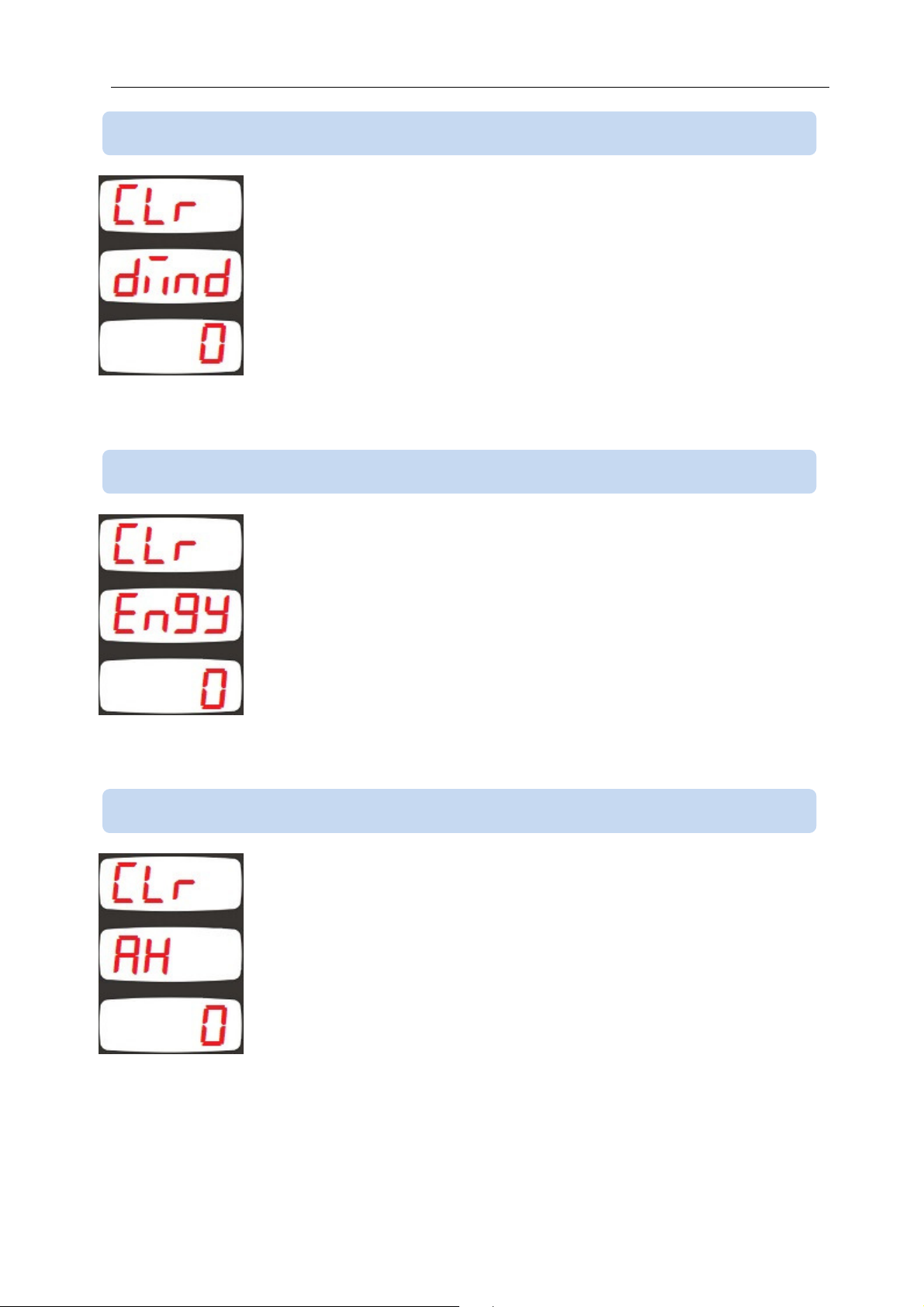
4.2 RESETTING DEMANDS
Parameter value
0: No operation
1: Reset demand counters
Setting this parameter to 1 causes demand and max_demand values to
be reset.
The parameter value is not saved and always reads 0.
4.3 RESETTING ENERGY COUNTERS
Parameter value
0: No operation
1: Reset kWh counters
Setting this parameter to 1 causes both positive and negative energy
counters (kWh) values to be reset.
The parameter value is not saved and always reads 0.
4.4 RESETTING Ah (ampere*hour) COUNTERS
Parameter value
0: No operation
1: Reset Ah counters
Setting this parameter to 1 causes both positive and negative
ampere*hour counters (Ah) values to be reset.
The parameter value is not saved and always reads 0.
14
Page 15
DKM-250 User Manual V-2.0
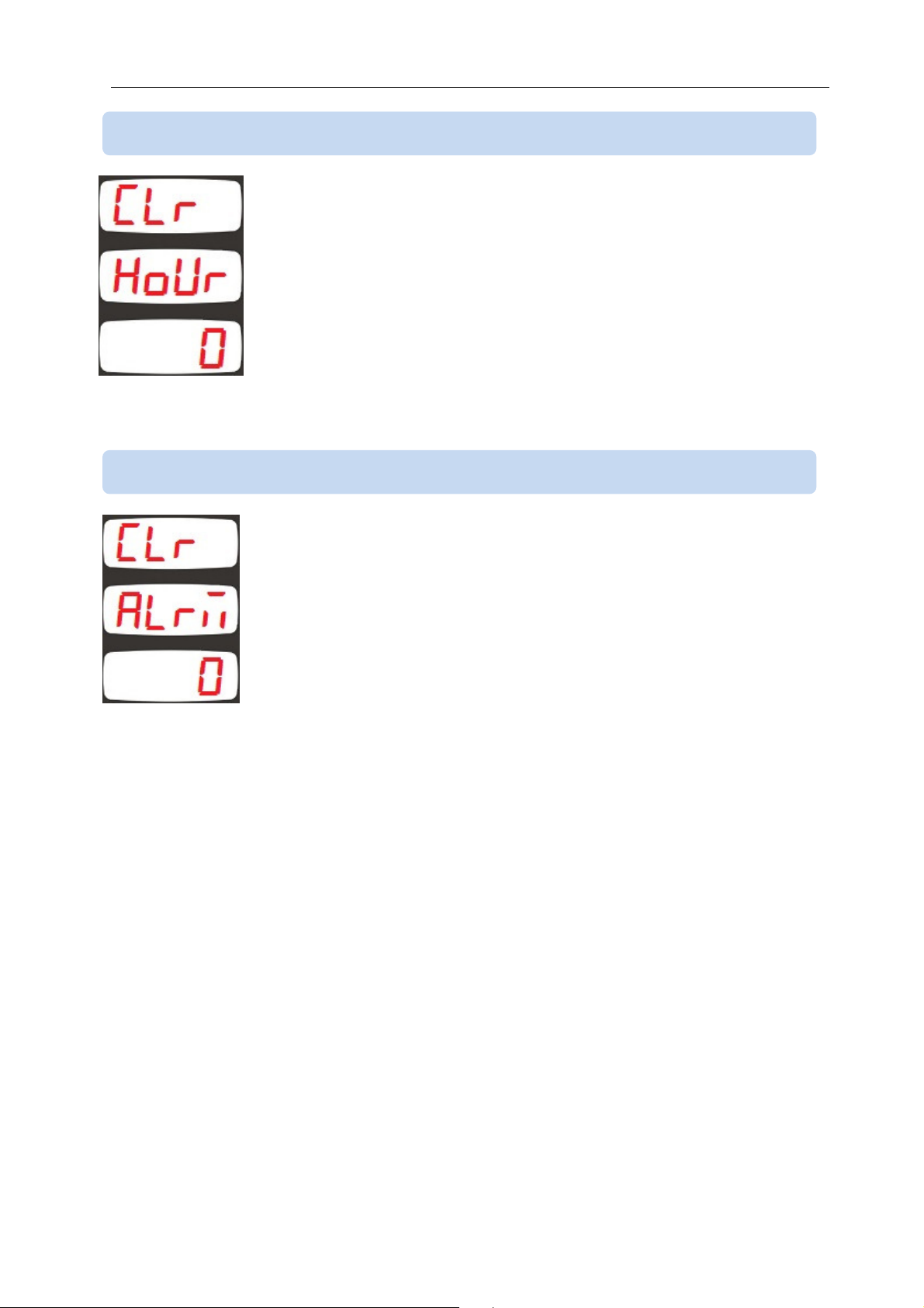
4.5 RESETTING RUN HOURS
Parameter value
0: No operation
1: Reset hour counter
Setting this parameter to 1 causes the run hour counter to be reset.
The parameter value is not saved and always reads 0.
4.6 RESETTING ALARMS
Parameter value
0: No operation
1: Reset alarms
Setting this parameter to 1 causes alarms to be reset.
The parameter value is not saved and always reads 0.
15
Page 16
DKM-250 User Manual V-2.0
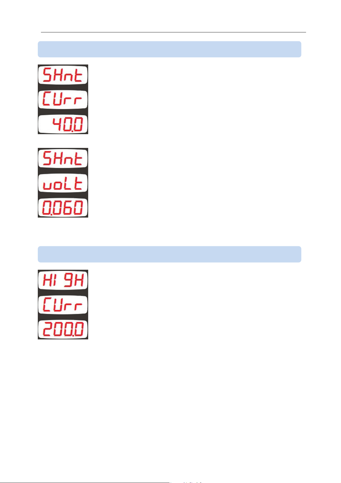
4.7 ADJUSTING CURRENT MEASUREMENT INPUT
This parameter adjusts the rated value of the current shunt in
amperes.
The factory set value is 40.0A
Adjustement range is between 0.1 and 3200amperes
This parameter adjusts the rated voltage of the current shunt in volts.
The factory set value is 0.060V
Adjustement range is between 0.001 and 0.100volts.
4.8 ADJUSTING CURRENT HIGH LIMIT
This parameter adjusts the overcurrent limit.
Positive and negative currents are monitored for their absolute value
and the alarm occurs for any direction of the current.
If this parameter is adjusted to 3200 (DISB ,DISB) then the
overcurrent limit is not monitored and the overcurrent alarm does not
occur.
Factory set value is 3200A
Adjustment range is between 0.1A and 3200A
16
Page 17

DKM-250 User Manual V-2.0
4.9 ADJUSTING VOLTAGE LOW AND HIGH LIMITS
This parameter adjusts the upper limit of the high voltage alarm.
If this parameter is set to 400.0 (DISB ,DISB) then high voltage is not
monitored and no alarm occurs.
Factory set value is 400.0V
Adjustment range is between 0.1 and 400.0V
This parameter adjusts the lower limit of the low voltage alarm.
If this parameter is set to 0.0 (DISB ,DISB) then low voltage is not
monitored and no alarm occurs.
Factory set value is 0.0V
Adjustment range is between 0.0 and 300.0V
4.10 SELECTING VOLTAGE MEASUREMENT INPUT
This parameter selects the voltage threshold where the voltage
measurement switches from the sensitive range normal range.
Factory set value is 70.0V.
Adjustment range is between 0.00V and 70.00V.
17
Page 18
DKM-250 User Manual V-2.0
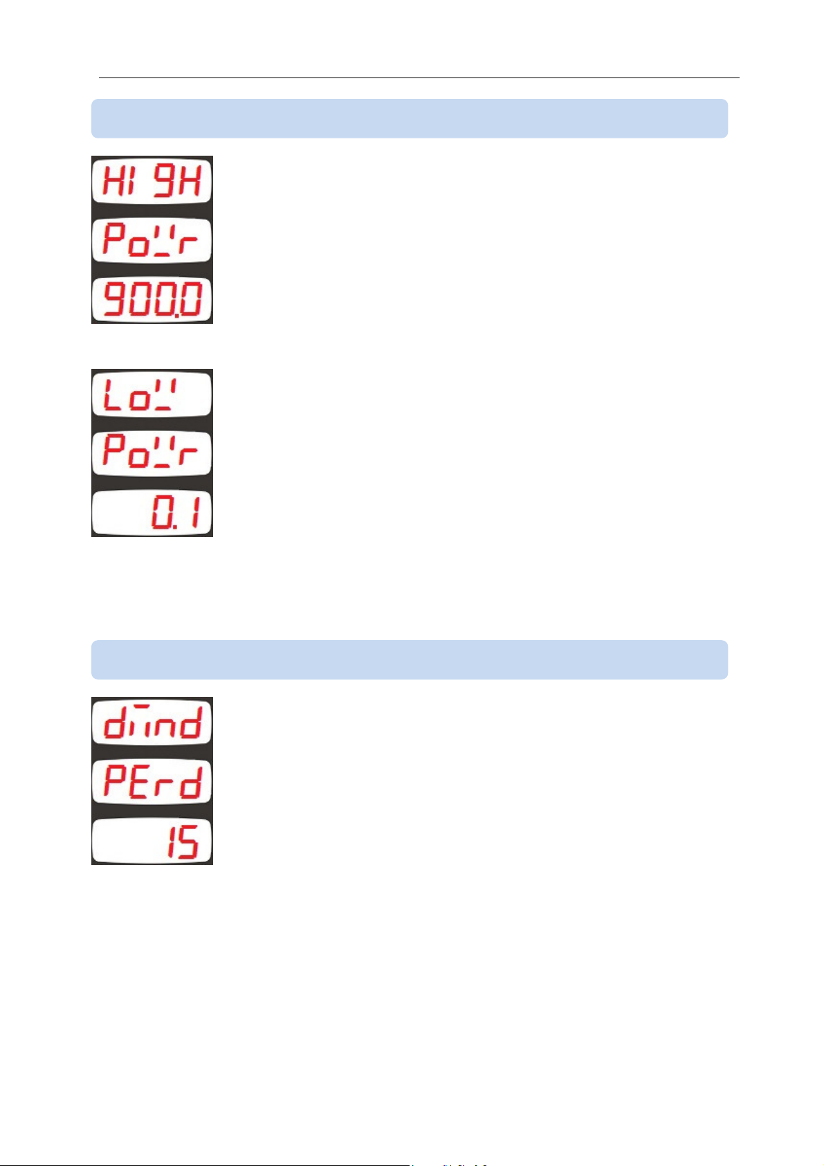
4.11 ADJUSTING LOW AND HIGH POWER LIMITS
This parameter adjusts the upper limit of the high power alarm.
Positive and negative powers are monitored for their absolute value
and the alarm occurs for any direction of the power flow.
If this parameter is set to 0.0 then high power is not monitored and no
alarm occurs.
Factory set value is 0.0kW
Adjustment range is between 0.0 and 3200.0kW
This parameter adjusts the lower limit of the low power alarm. Positive
and negative powers are monitored for their absolute value and the
alarm occurs for any direction of the power flow.
If this parameter is set to 0.0 then high power is not monitored and no
alarm occurs.
Factory set value is 0.0kW
Adjustment range is between 0.0 and 3200.0kW
4.12 ADJUSTING THE DEMAND PERIOD
This parameter determines the demand period for voltage, current
and power measurements. The average value is calculated during the
demand period and at the end of the period new demand values
overwrite older values.
Factory set value is 15 minutes.
Adjustment range is 1 to 240 minutes.
18
Page 19
DKM-250 User Manual V-2.0
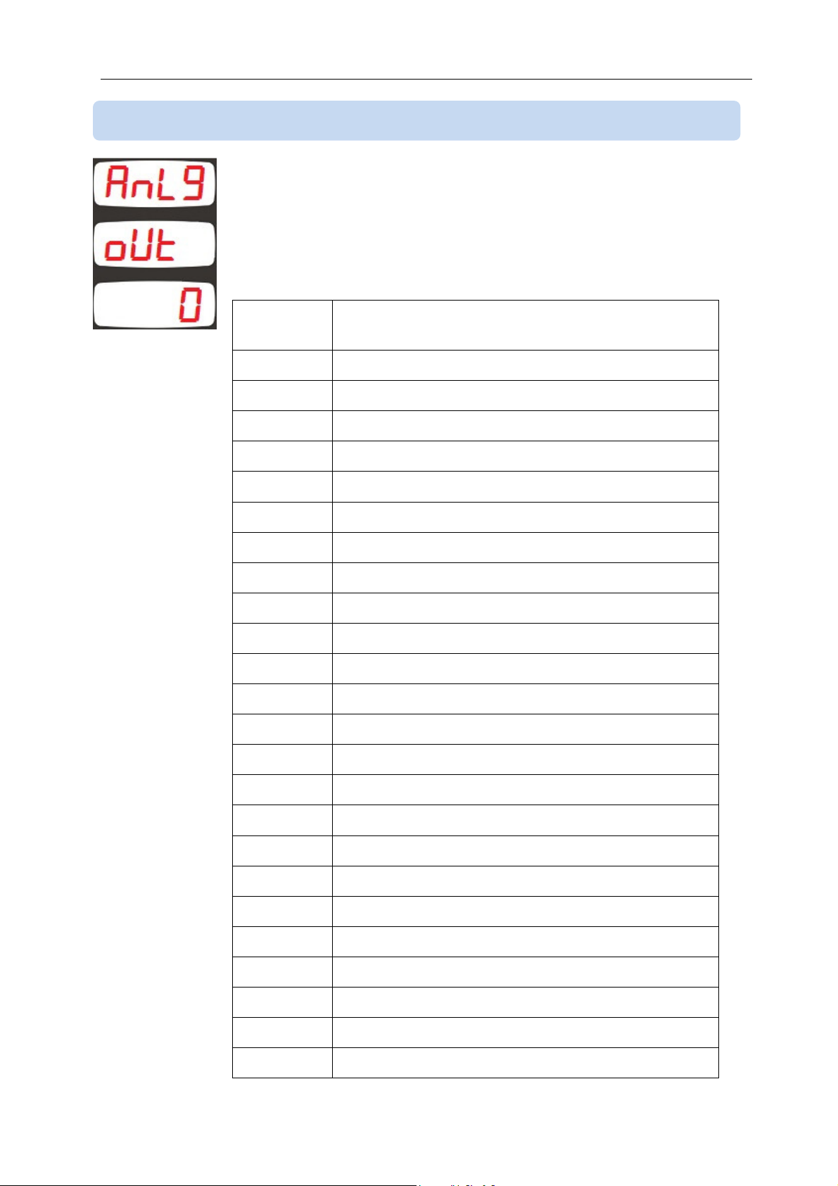
4.13 ADJUSTING THE 4-20mA ANALOG OUTPUT
This parameter determines the analog value to be output from the 420mA analog output.
Factory set value is 0.
Adjustment range is 0 to 22.
Parameter
value
10 Maximum current demand (negative direction)
11 Maximum power demand (positive direction)
Measurement at output
0 Instantaneous voltage (V)
1 Instantaneous current (A)
2 Instantaneous power (kW)
3 Current demand (absolute value)
4 Current demand (positive direction)
5 Current demand (negative direction)
6 Power demand (positive direction)
7 Power demand (negative direction)
8 Maximum Voltage Demand
9 Maximum current demand (positive direction)
12 Maximum power demand (negative direction)
13 Maximum Voltage
14 Minimum Voltage
15 Maximum current (positive direction)
16 Minimum current (positive direction)
17 Maximum power (positive direction)
18 Minimum power (positive direction)
19 Maximum current (negative direction)
20 Minimum current (negative direction)
21 Maximum power (negative direction)
22 Minimum power (negative direction)
23 Earth leakage percent (%)
19
Page 20
DKM-250 User Manual V-2.0
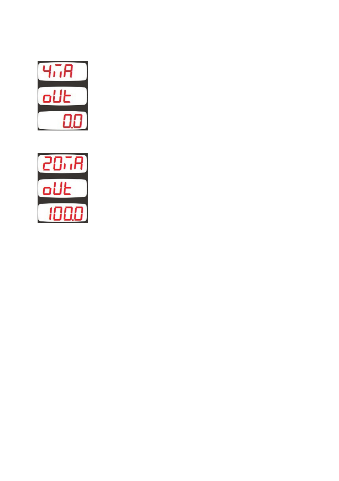
This parameter defines the value corresponding to 4mA current
output. (low limit)
Factory set value is 0.
Adjustment range is between -999.9 and 3000.0
This parameter defines the value corresponding to 20mA current
output. (high limit)
Factory set value is 100.0.
Adjustment range is between -999.9 and 3200.0
20
Page 21
DKM-250 User Manual V-2.0
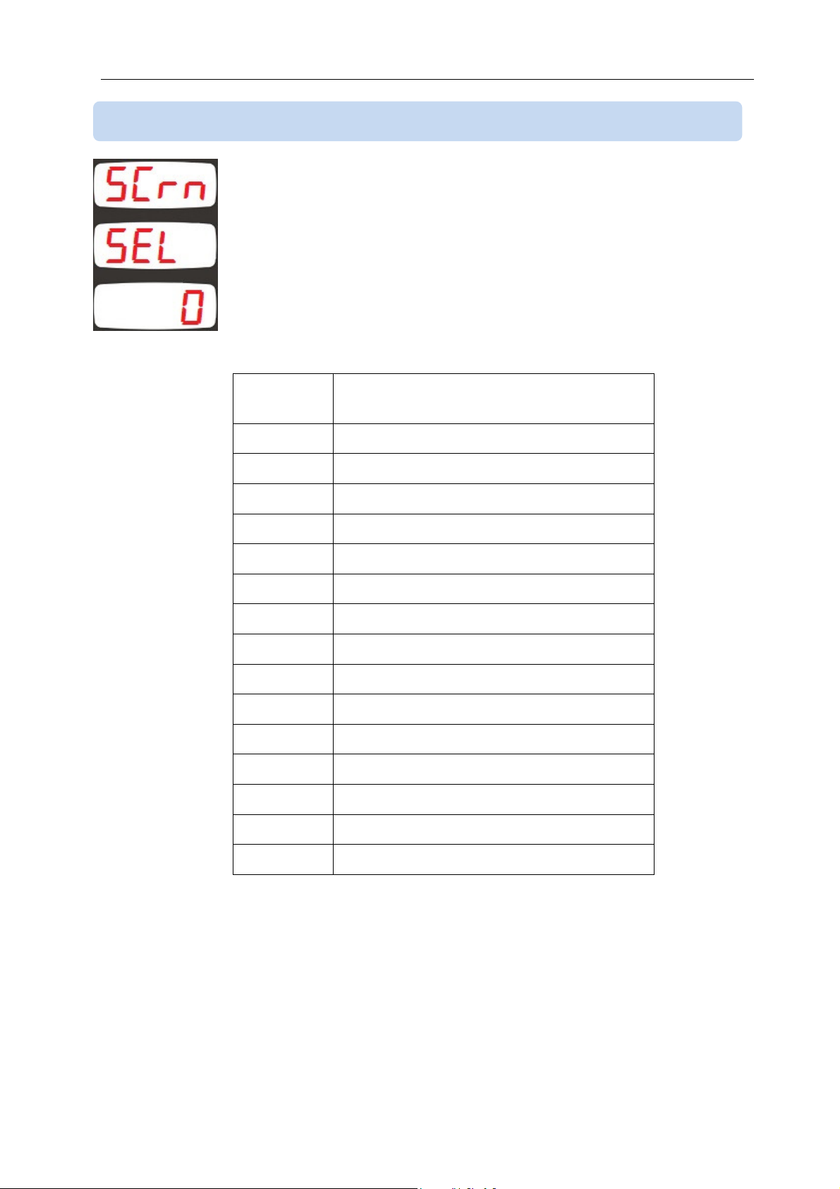
4.14 SELECTING THE DEFAULT SCREEN
This parameter selects the screen menu where the unit returns when
no pushbutton is pressed during 5 minutes.
It also determines the screen that comes when the programming
mode is closed.
Factory set value is 0.
Adjustment range is 0 to 13.
Parameter
Display menu
valuei
0 Instantaneous measurements
1 Earth leakage percent (%)
2 Ah counter (positive direction)
3 Ah counter (negative direction)
4 kWh counter (positive direction)
5 kWh counter (negative direction)
6 Total run hour counter
7 Minimum values (positive direction)
8 Minimum values (negative direction)
9 Maximum values (positive direction)
10 Maximum values (negative direction)
11 Demand values (positive direction)
12 Demand values (negative direction)
13 Max demand values (positive direction)
14 Max demand values (negative direction)
21
Page 22
DKM-250 User Manual V-2.0
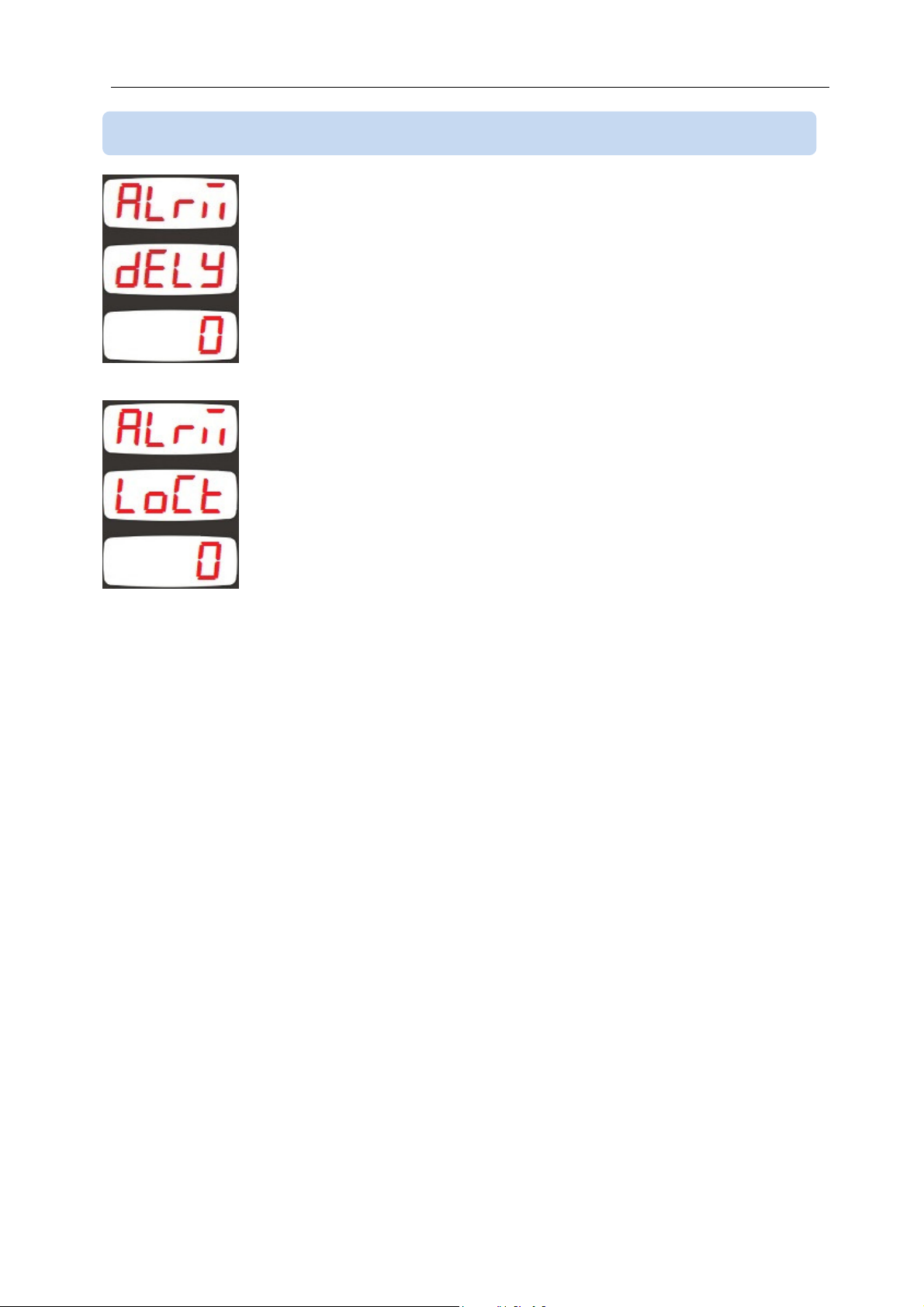
4.15 ALARM CONFIGURATION
This parameter determines the delay between an alarm condition
occurs and the alarm given.
Factory set value is 0.
Adjustment range is 0 to 255 seconds.
0: Alarm lock disabled
1: Alarm lock enabled
When this parameter is set to 1, even if the alarm cause is removed,
alarms will persist until manually reset.
When this parameter is set to 0, when the alarm cause is removed,
alarms automatically disappear.
Factory set value is 0.
Adjustment range is 0 to 1.
22
Page 23
DKM-250 User Manual V-2.0
4.16 MODBUS PARAMETERS
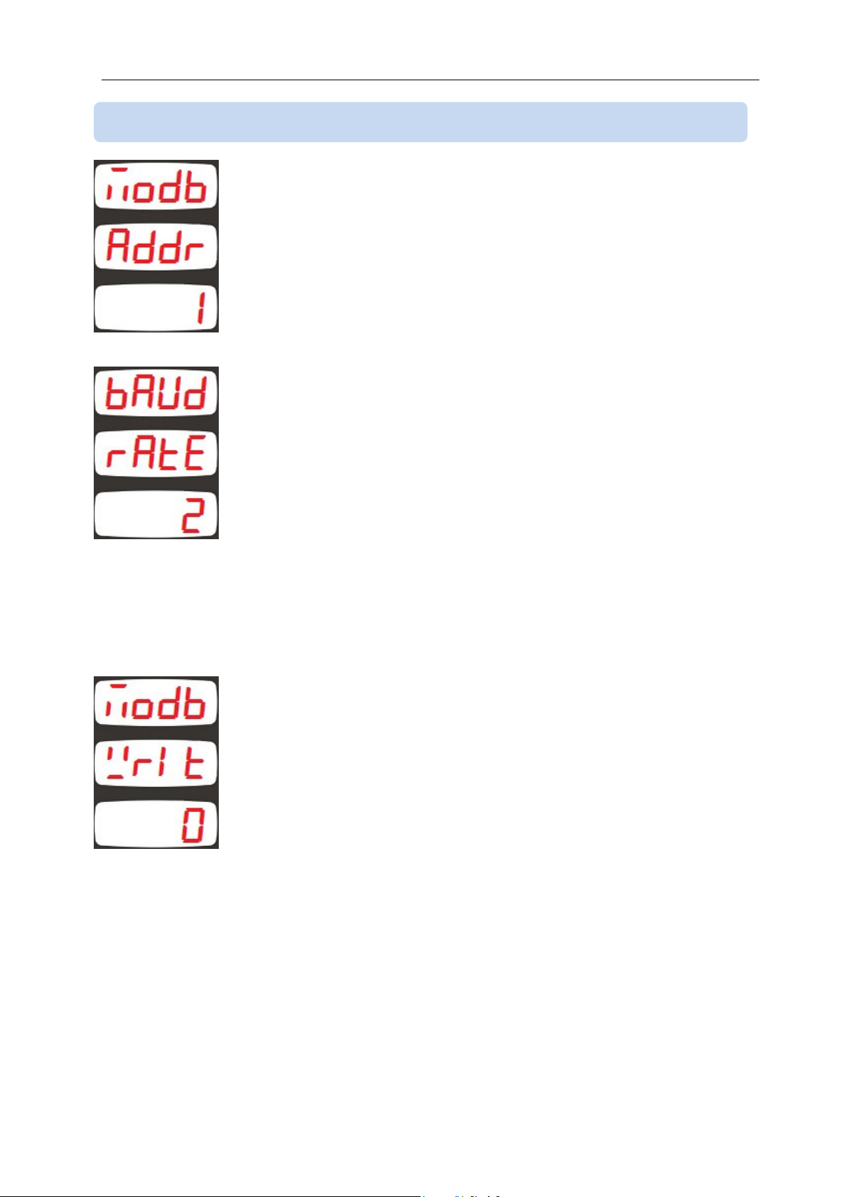
This parameter determines the Modbus node address of the unit.
Every unit in the same Modbus loop must have a different node
address.
Factory set value is 1.
Adjustment range is 0 to 245.
This parameter determines the data rate (baud rate) used in the
Modbus communication. Every unit in the same Modbus loop must
use the same data rate.
0: Baud rate = 2400
1: Baud rate = 4800
2: Baud rate = 9600
3: Baud rate = 19200
4: Baud rate = 38400
Factory set value is 2.
Adjustment range is 0 to 4.
If this parameter is set to a value different from 0, then the unit will
require this parameter as a password prior to Modbus writes or
Modbus commands.
If the parameter is set to 0 then no password is required.
Factory set value is 0.
Adjustment range is 0 to 9999.
23
Page 24
DKM-250 User Manual V-2.0
4.17 ADJUSTING LOW AND HIGH EARTH LEAKAGE LIMITS
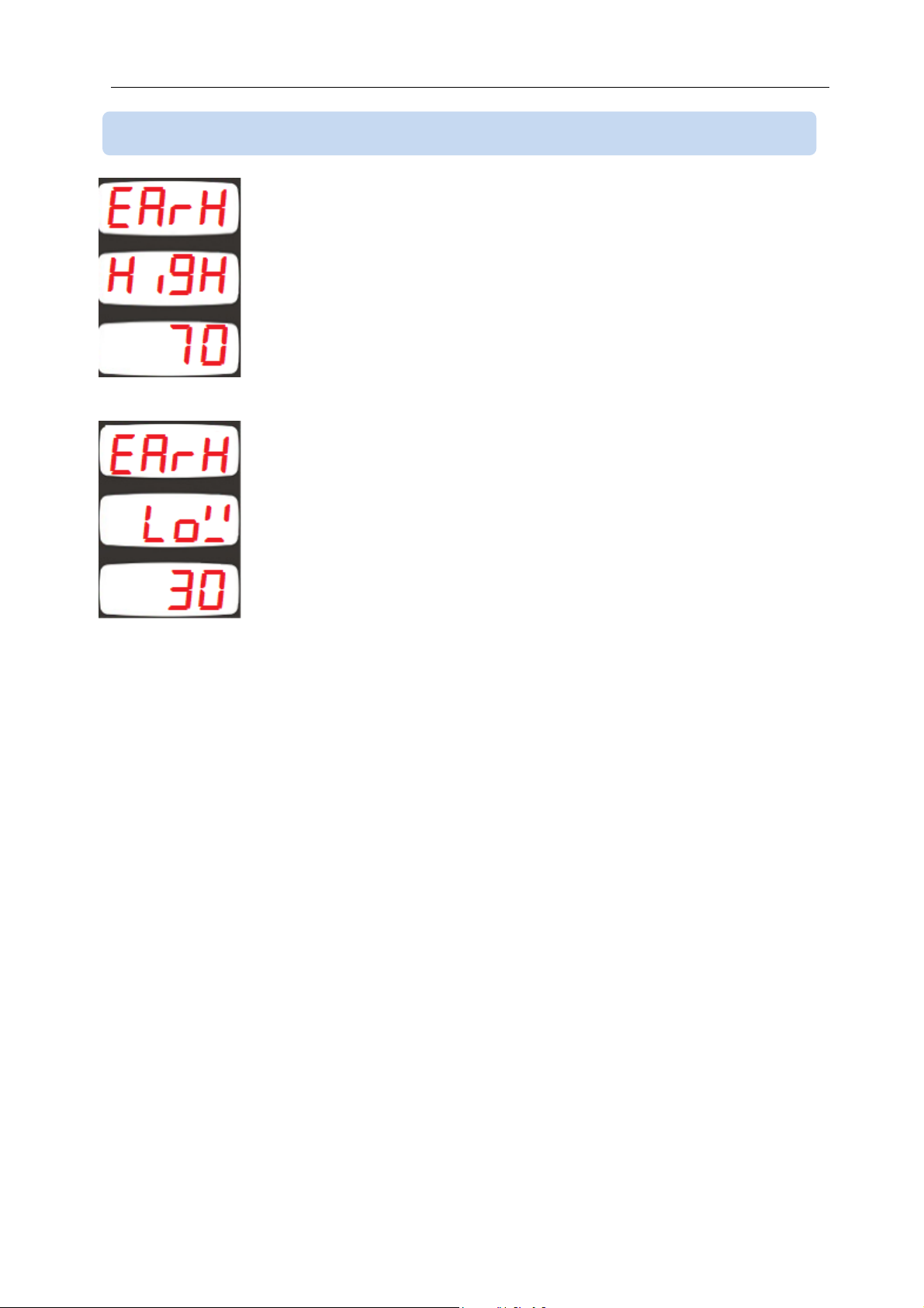
This parameter adjusts the upper limit of the ratio of the earth voltage
to supply voltage.
The factory set value is 70%.
Adjustment range is 0 to 100%
This parameter adjusts the lower limit of the ratio of the earth voltage
to supply voltage.
The factory set value is 30%.
Adjustment range is 0 to 100%
24
Page 25
DKM-250 User Manual V-2.0
4.18 PROGRAMMABLE RELAY SETUP
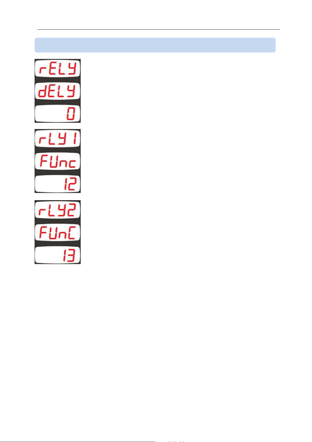
This is the wait delay between the conditions that will activate the
relay occur and the relay is activated.
The factory set value is 0.
Adjustment range is 0 to 255 seconds.
This parameter selects the RELAY_1 function.
The factory set value is 12.
Adjustment range is 0 to 17
This parameter selects the RELAY_2 function.
The factory set value is 13.
Adjustment range is 0 to 17
25
Page 26
DKM-250 User Manual V-2.0
Value
Relay function
Relay function is selected from below list:
0 1 High voltage alarm
2 Low voltage alarm
3 High current alarm
4 High power (kW) alarm
5 Low power (kW) alarm
6 Positive (+) earth leakage alarm
7 Negative (+) earth leakage alarm
8 Active if any alarm occurs
9 Low or high voltage alarm
10 Low or high power (kW) alarm
11 Positive (+) or negative (-) earth
leakage alarm
12 Follows the digital input_1
13 Follows the digital input_2
14 kWh, Ah or hour pulse
15 If the value 1234 is written to
Modbus address 35 then the
function is active
16 If the value 1234 is written to
Modbus address 36 then the
function is active
17 -
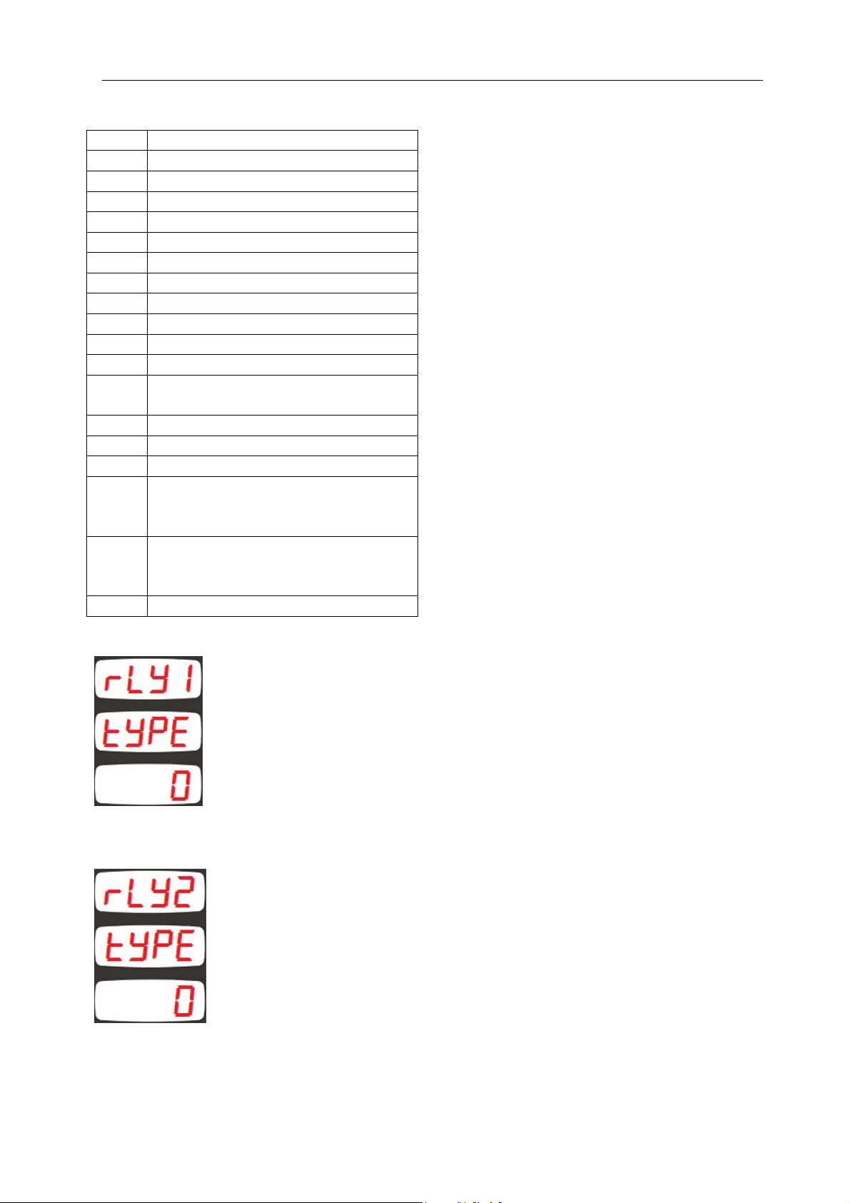
This parameter determines the RELAY_1 contact type.
0: Normally open (NO)
1: Normally closed (NC)
The factory set value is 0.
Adjustment range is 0 to 1.
This parameter determines the RELAY_2 contact type.
0: Normally open (NO)
1: Normally closed (NC)
The factory set value is 0.
Adjustment range is 0 to 1.
26
Page 27
DKM-250 User Manual V-2.0
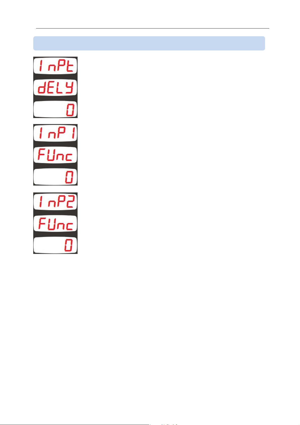
4.19 PROGRAMMABLE DIGITAL INPUT SETUP
This parameter determines the wait delay between the digital input
signal and the activation of input function.
The factory set value is 0.
Adjustment range is 0 to 80 seconds.
This parameter selects the function performed when the digital
input_1 signal is active.
The factory set value is 0.
Adjustment range is 0 to 11.
This parameter selects the function performed when the digital
input_2 signal is active.
The factory set value is 0.
Adjustment range is 0 to 11.
27
Page 28
DKM-250 User Manual V-2.0
Value
Function when signal is active
Function when signal is passive
Digital input functions are selected from below list:
0 - 1 kWh and Ah counters operate kWh and Ah counters are stopped
2 When signal is activated, kWh and Ah
counters are reset, then they start
kWh and Ah counters are stopped
counting
3 kWh, Ah and hours-run counters
operate
4 When signal is activated, kWh, Ah and
hours-run counters are reset, then
kWh, Ah and hours-run counters are
stopped
kWh, Ah and hours-run counters are
stopped
they start counting
5 hours-run counter operates hours-run counter is stopped
6 When signal is activated, the hours-
hours-run counter is stopped
run counter is reset, then it starts
counting
7 When signal is activated, kWh and Ah
-
counters are reset
8 When signal is activated, The hours-
-
run counter is reset
9 When signal is activated, kWh and Ah
-
counters are reset
10 Alarms are reset 11 When signal is active, displays turn off Displays operate normally
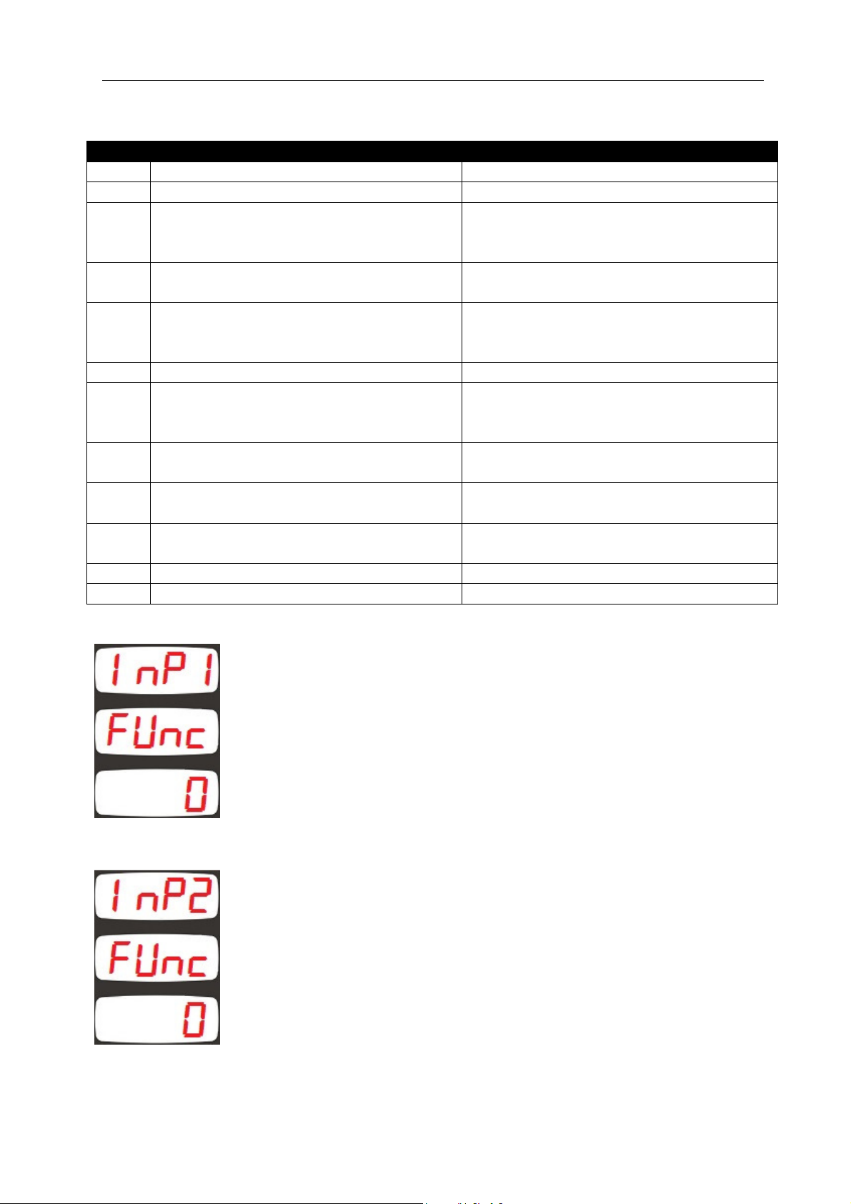
This parameter selects when the input function is activated for the
digital input_1.
0: active when signal present
1: active when signal is absent
The signal is applied to digital inputs with the polarity shown in the
installation diagram.
The factory set value is 0.
This parameter selects when the input function is activated for the
digital input_2.
0: active when signal present
1: active when signal is absent
The signal is applied to digital inputs with the polarity shown in the
installation diagram.
The factory set value is 0.
28
Page 29
DKM-250 User Manual V-2.0
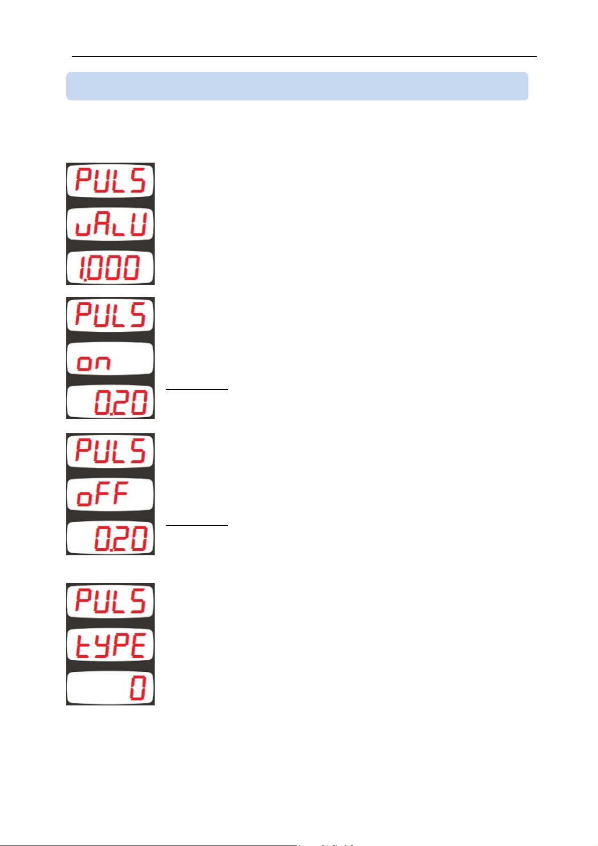
4.20 OUTPUT PULSE (kWh, Ah, hour) SETUP
If any of relay functions (explained in chapter 4.17) is set to 14 (kWh, Ah or hour-run pulse),
then below parameters will determine the pulse charateristics.
This parameter defines the counter increment step to provide 1 pulse.
The factory set value is 1.000 kWh or Ah or hour.
Adjustement range is 0.001 to 10.000
This parameter defines the active pulse duration in seconds.
The factory set value is 0.20 second (200 ms).
Adjustment range is 0.10 to 9.99 seconds.
WARNING: Excessive pulse duration may cause a missing pulse.
This parameter defines the minimum duration between 2 pulses.
The factory set value is 0.20 second (200 ms).
Adjustment range is 0.10 to 9.99 seconds.
WARNING: Excessive duration may cause a missing pulse.
This parameter determines the counter providing pulses.
0: Positive direction kWh counter
1: Negative direction kWh counter
2: Positive direction Ah counter
3: Negative direction Ah counter
4: Total hours-run counter
The factory set value is 0.
Adjustment range is 0 to 4 seconds.
29
Page 30
DKM-250 User Manual V-2.0
4.21 DISPLAYING THE FIRMWARE VERSION
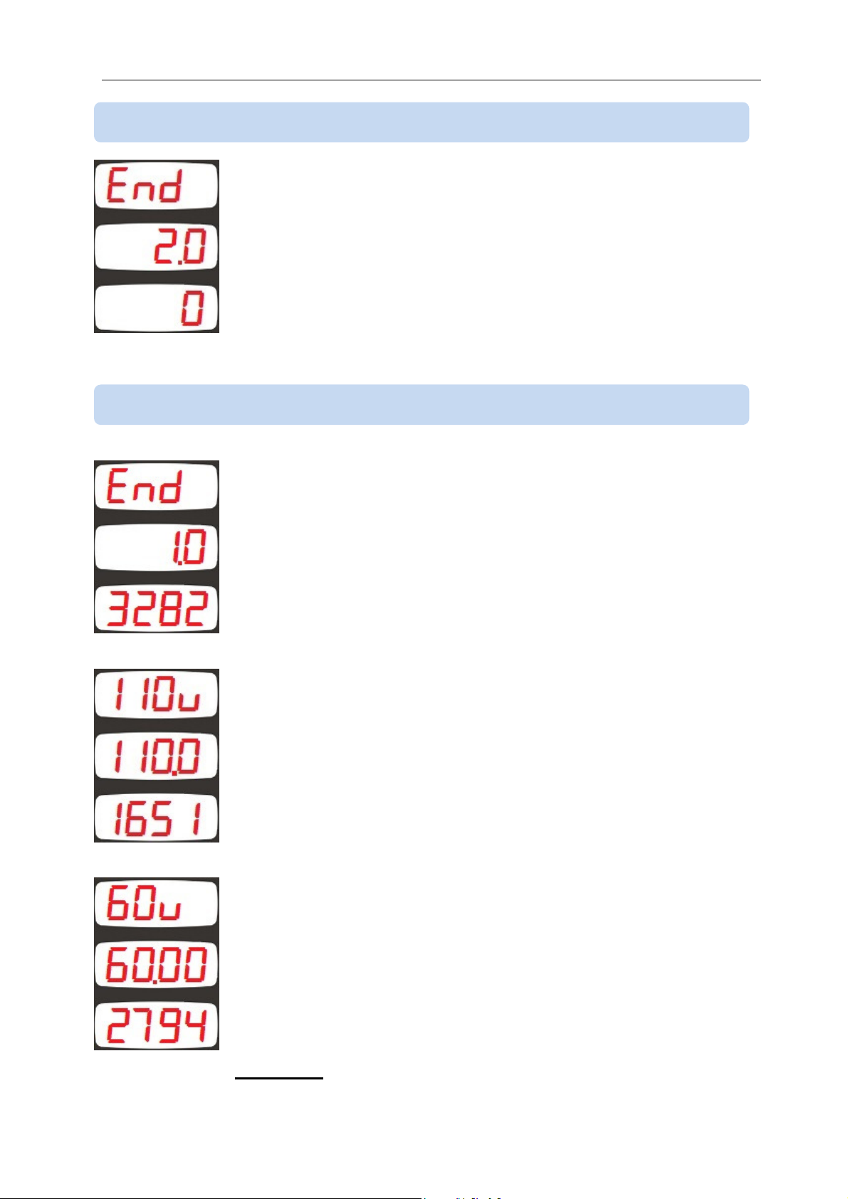
The firmware version is displayed in te second line of the “end
end , End”
end end
screen.
Any inquiry to the manufacturer must state the firmware version in
question.
4.22 CALIBRATION
The unit leaves the production in a calibrated status.
If recalibration is required, enter the password “3282” to the third line
of the “end
end , End” screen and press the SET button.
end end
The calibration screen about the 110V voltage input will be seen. The
first display will show “110V”. The second screen will display the
measured instantaneous voltage from the input. The third display will
display the calibration coefficient (high 4 digits only)
Adjust UP and DOWN menu buttons until the value displayed in the
second screen is correct.
When the value is correct then press SET button. The unit will switch
to 60V voltage input calibration.
In 60V input calibration mode, the first display will show “60V”. The
second screen will display the measured instantaneous voltage from
the input. The third display will display the calibration coefficient (high
4 digits only)
Adjust UP and DOWN menu buttons until the value displayed in the
second screen is correct.
When the value is correct then press SET button. The unit will switch
to first current input zero point calibration.
WARNING: The supply voltage should not exceed 70VDC.
30
Page 31
DKM-250 User Manual V-2.0
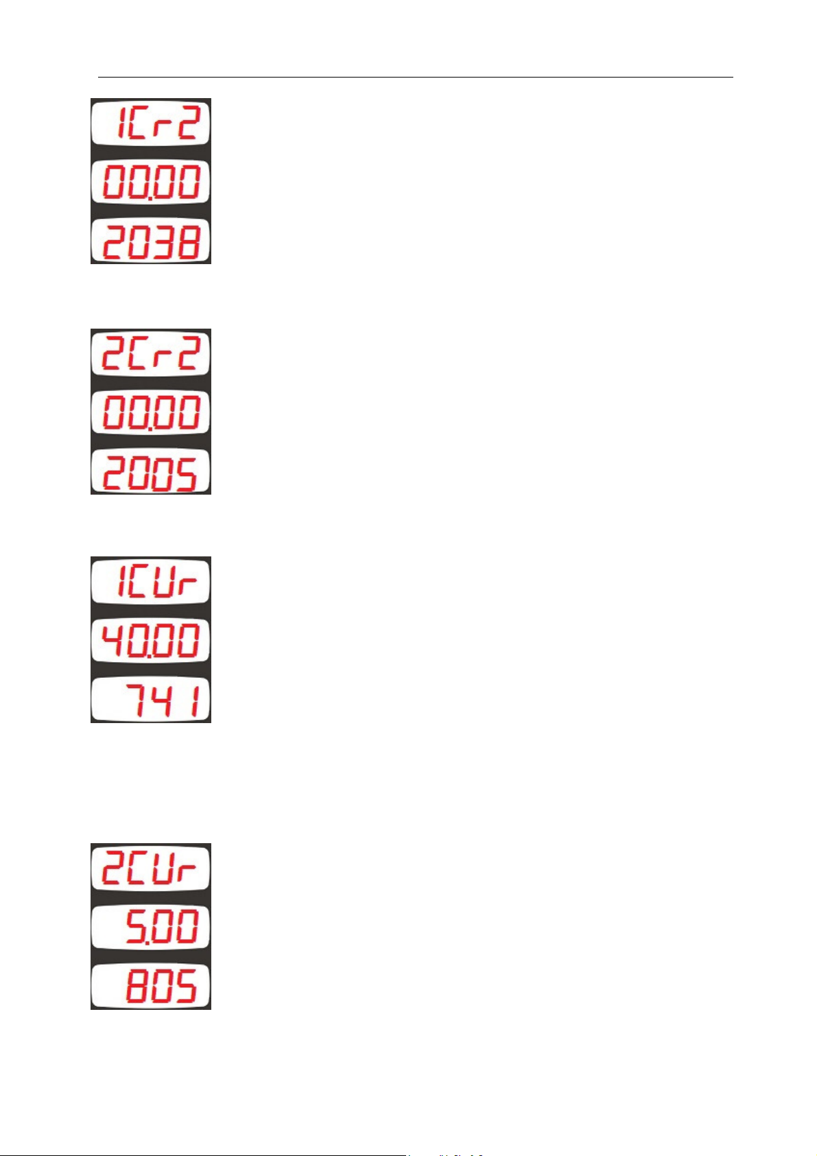
In the first current input zero mode, the first display will show “1CRZ”.
The second screen will display the measured instantaneous current
from the input. The third display will display the offset value causing
display 00.00 at no current.
Adjust UP and DOWN menu buttons until the value displayed in the
second screen is correct.
When the value is correct then press SET button. The unit will switch
to second current input zero point calibration.
In the second current input zero mode, the first display will show
“2CRZ”. The second screen will display the measured instantaneous
current from the input. The third display will display the offset value
causing display 00.00 at no current.
Adjust UP and DOWN menu buttons until the value displayed in the
second screen is correct.
When the value is correct then press SET button. The unit will switch
to first current input sensitivity calibration.
In the first current input sensitivity calibration mode, the first display
will show “1CUR”. The second screen will display the measured
instantaneous current from the input. The third display will display the
calibration coefficient (high 4 digits only)
Adjust UP and DOWN menu buttons until the value displayed in the
second screen is correct.
When the value is correct then press SET button. The unit will switch
to second current input sensitivity calibration.
The second current input is internal and makes a more precise
measurement in low currents. The switching between two internal
inputs is automatic. Between -10mV and +10mV the sensitive input is
used. Above this signal amplitude the normal input is active.
In the second current input sensitivity calibration mode, the first
display will show “2CUR”. The second screen will display the
measured instantaneous current from the input. The third display will
display the calibration coefficient (high 4 digits only)
Adjust UP and DOWN menu buttons until the value displayed in the
second screen is correct.
When the value is correct then press SET button. The unit will switch
to Vin voltage calibration.
31
Page 32
DKM-250 User Manual V-2.0
Vin voltage is generated internally and used to check that the internal
power supply is operating.
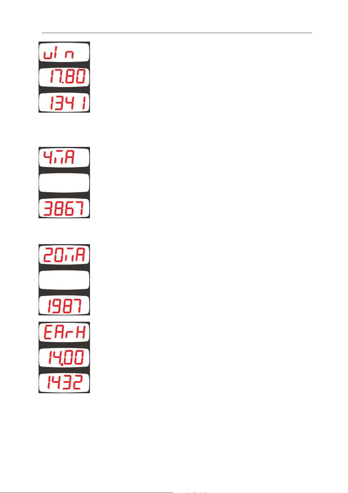
In Vin calibration mode, the first display will show “vIn”. The second
screen will display the measured instantaneous Vin voltage. The third
display will display the calibration coefficient (high 4 digits only)
Adjust UP and DOWN menu buttons until the value displayed in the
second screen is correct. In normal operation Vin should be
17.80volts.
When the value is correct then press SET button. The unit will switch
to 4mA calibration of the 4-20mA output.
In 4mA calibration mode, the first display will show “4mA”. The
second display is blank. The third display will show the calibration
coefficient necessary to send 4mA from the analog output.
Measure the analog output with a precision ampermeter. Adjust UP
and DOWN menu buttons until the value displayed in the ampermeter
is 4.00mA.
When the value is correct then press SET button. The unit will switch
to 20mA calibration of the 4-20mA output.
In 20mA calibration mode, the first display will show “20mA”. The
second display is blank. The third display will show the calibration
coefficient necessary to send 20mA from the analog output.
Measure the analog output with a precision ampermeter. Adjust UP
and DOWN menu buttons until the value displayed in the ampermeter
is 20.00mA.
When the value is correct then press SET button.
In earth voltage calibration mode, the first display will show “EarH”.
The second display shows the instantaneous voltage measured at the
EARTH input. The third display shows the calibration coefficient.
If no earth leakage is present (input open) then half the supply voltage
should be measured. Adjust UP and DOWN menu buttons until the
value displayed in half the supply voltage.
When the value is correct then press SET button.
As this is the last calibration parameter, the display will switch to the
first calibration parameter, which is 110V voltage input calibration.
32
Page 33

DKM-250 User Manual V-2.0
4.23 LAMP TEST
When programming is over, hold pressed UP and DOWN MENU
buttons for 2 seconds.
The unit will exit program mode and will turn on all lights for lamp
testing purpose.
Check that all lights are on.
Press any button to resume normal operation.
33
Page 34
DKM-250 User Manual V-2.0
Byte
Description
Value
5. MODBUS COMMUNICATIONS
5.1. DESCRIPTION
The unit offers serial data communication port allowing it to be integrated in automation
systems.
The serial port is of RS-485 MODBUS-RTU standard. It is fully isolated from power supply
and measurement terminals for failure-free operation under harsh industrial conditions.
The MODBUS properties of the unit are:
-Data transfer mode: RTU
-Serial data: 2400-38400 bps, 8 bit data, no parity, 1 bit stop
-Supported functions:
-Function 3 (Read multiple registers)
-Function 6 (Write single register)
-Function 10 (Write multiple register)
-The answer to an incoming message is sent with a minimum of 4.3ms delay after
message reception.
Each register consists of 2 bytes (16 bits). Larger data structure contain multiple registers.
Detailed description about the MODBUS protocol is found in the document “Modicon
Modbus Protocol Reference Guide”. This document may be downloaded at:
http://www.modbus.org/specs.php
Data Reading
The function 03 (read multiple registers) will be used for data reading. The MODBUS
master will send a query. The answer will be one of the below:
-A response containing the requested data
-An exceptional response indicating a read error.
The maximum number of registers read in one message is 120. If more registers are
requested, the unit will send only the first 120 registers.
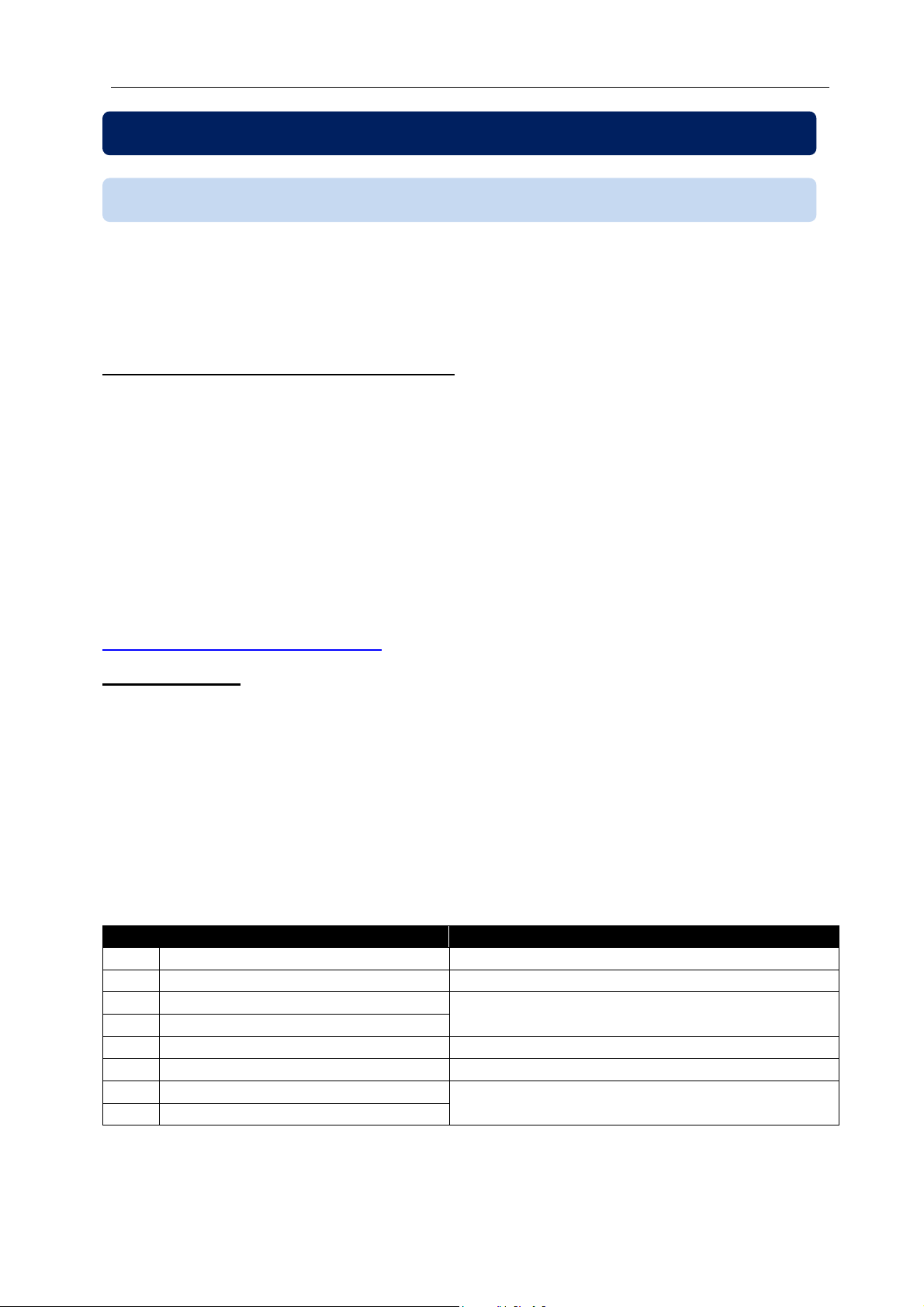
The query message specifies the starting register and quantity of registers to be read. The
message structure is below:
0 Controller address 1 to 254
1 Function code 3
2 Starting address high See below the description of available
3 Starting address low
4 Number of registers high always 0
5 Number of registers low max 78h (120 decimal)
6 CRC low byte See below for the checksum calculation
7 CRC high byte
Here is the sequence to read 16 registers starting from address 20h (32 decimal):
01 03 00 20 00 10 45 CC (each byte is expressed as 2 hexadecimal characters)
registers
34
Page 35
DKM-250 User Manual V-2.0
Byte
Description
Value
bytes
Byte
Description
Value
Byte
Description
Value
The checksum value in the above message may be used for the verification of checksum
calculation algorithm.
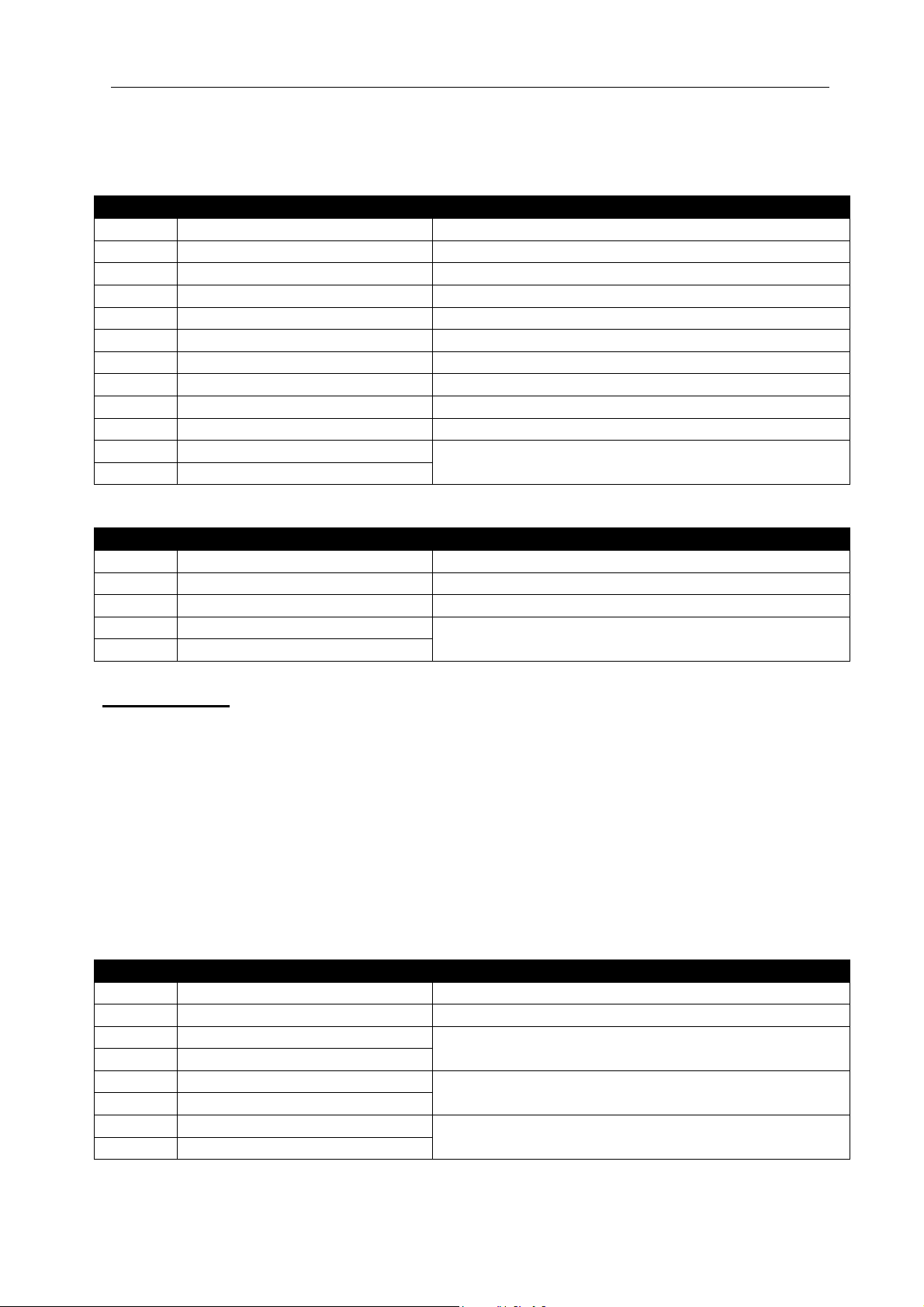
The normal response will be:
0 Controller address same as in the query
1 Function code 3
2 Data lenght in
(L) number of registers * 2
3 High byte of 1st register
4 Low byte of 1st register
5 High byte of 2nd register
6 Low byte of 2nd register
....
L+1 High byte of the last register
L+2 Low byte of the last register
L+3 CRC low byte See below for the checksum calculation
L+4 CRC high byte
The exceptional response will be:
0 Controller address same as in the query
1 Function code 131 (function code + 128)
2 Exception code 2 (illegal address)
3 CRC low byte See below for the checksum calculation
4 CRC high byte
Data Writing
The function 06 (write single register) or function 10h (write multiple registers) is used for
data writing. A maximum of 32 registers can be written at a time.
The MODBUS master will send a query containing data to be written. The answer will be
one of the below:
-A normal response confirming successful write,
-An exceptional response indicating a write error.
Only some of the available registers are authorized to be written. An attempt to write a write
protected register will result to the exceptional response.
The query message specifies the register address and data. The message structure is
below:
0 Controller address 1 to 254
1 Function code 6
2 Register address high See below the description of available registers
3 Register address low
4 Data high byte
5 Data low byte
6 CRC low byte See below for the checksum calculation
7 CRC high byte
35
Page 36
DKM-250 User Manual V-2.0
Byte
Description
Value
Byte
Descrip
tion
Value
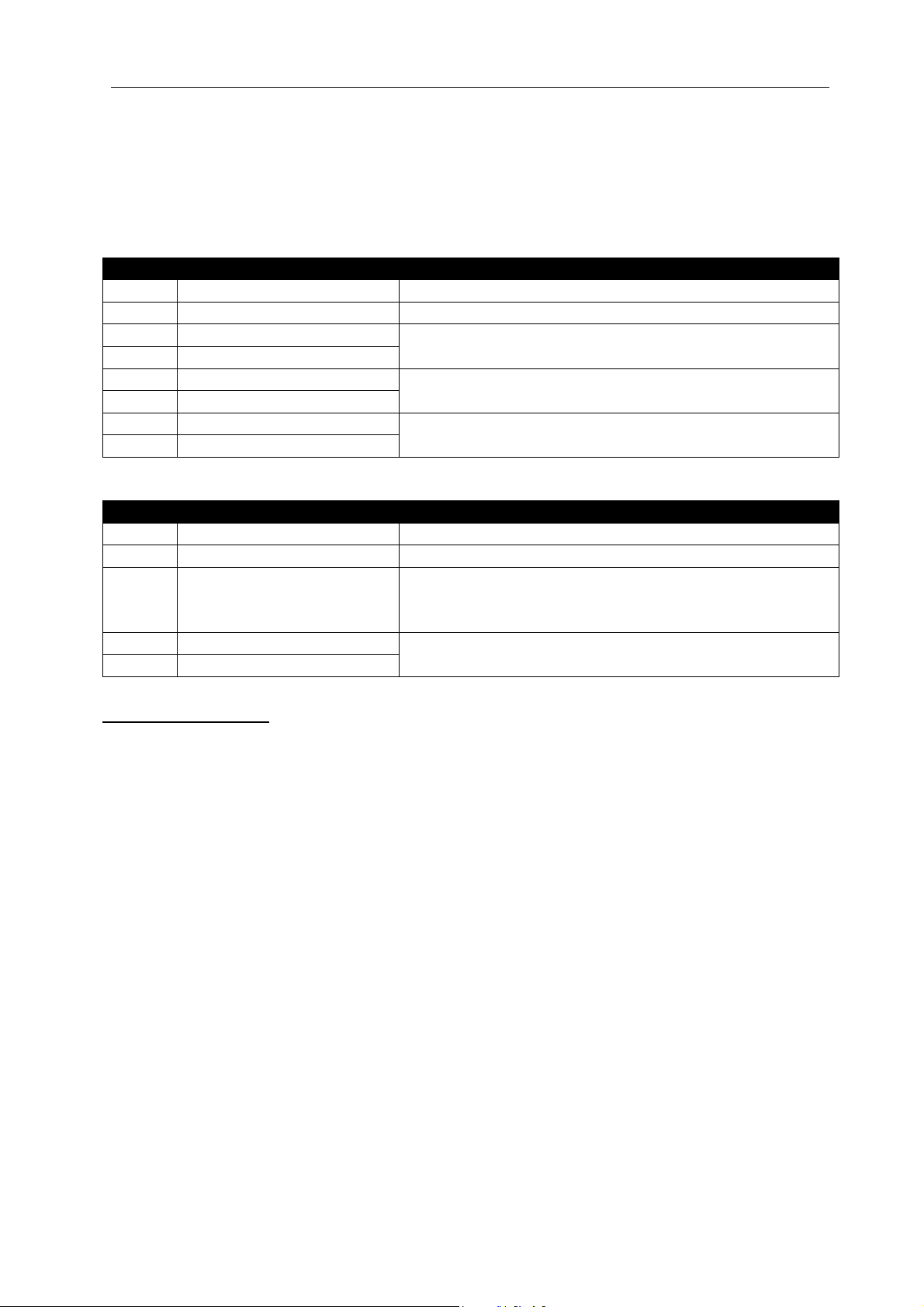
Here is the sequence to write the value 0010h to the register 40h (64 decimal):
01 06 00 40 00 10 89 D2 (each byte is expressed as 2 hexadecimal characters)
The checksum value in the above message may be used for the verification of checksum
calculation algorithm
The normal response will be the same as the query:
0 Controller address 1 to 254
1 Function code 6
2 Register address high See below the description of available registers
3 Register address low
4 Data high byte
5 Data low byte
6 CRC low byte See below for the checksum calculation
7 CRC high byte
The exceptional response will be:
0 Controller address same as in the query
1 Function code 134 (function code + 128)
2 Exception code 2 (illegal address)
or
10 (write protection)
3 CRC low byte See below for the checksum calculation
4 CRC high byte
CRC calculation
Here is a procedure for generating a CRC:
1) Load a 16–bit register with FFFF hex (all 1’s). Call this the CRC register.
2) Exclusive OR the first 8–bit byte of the message (the function code byte) with the low–
order byte of the 16–bit CRC register, putting the result in the CRC register.
3) Shift the CRC register one bit to the right (toward the LSB), zero–filling the MSB. Extract
and examine the LSB. The LSB is the least significant bit of the CRC before the shift
operation.
4) If the LSB is 1: Exclusive OR the CRC register with the polynomial value A001 hex.
5) Repeat Steps 3 and 4 until 8 shifts have been performed. Thus, a complete 8–bit byte
will be processed.
6) Repeat Steps 2 through 5 for the next 8–bit byte of the message. Continue doing this
until all bytes have been processed.
7) The final contents of the CRC register is the CRC value.
8) Place the CRC into the message such that the low byte is transmitted first. The algorithm
should give the correct CRC for below messages:
01 03 00 20 00 10 45 CC
01 06 00 40 00 10 89 D2
36
Page 37
DKM-250 User Manual V-2.0
Error codes
Only 3 error codes are used:
01: illegal function code
02: illegal address
10: write protection (attempt to write a read_only register)
Data types
Each register consists of 16 bits (2 bytes)
If the data type is a byte, only the low byte will contain valid data. High byte is don’t care.
For data type longer than 16 bits, consecutive registers are used. The least significant
register comes first.
5.2. COMMANDS
Commands to the unit are written to below addresses.
If the Modbus Write Password parameter (moDB WRIT
moDB WRIT)” is left 0 as in the factory settings,
moDB WRITmoDB WRIT
then the unit will not ask any password for Modbus commands and Modbus writes.
If the Modbus Write Password parameter (moDB WRIT
moDB WRIT)” is set to a value other than 0, then
moDB WRITmoDB WRIT
the unit will require a password for commands and data writes.
If the value recorded as Modbus Write Password parameter (moDB WRIT
moDB WRIT)” or 3271 is written
moDB WRITmoDB WRIT
to the address 7168, then during next 10 minutes, Modbus area can be written and below
commands can be executed. All commands (other than the password) may be activated by
writing a value other than zero to the related register.
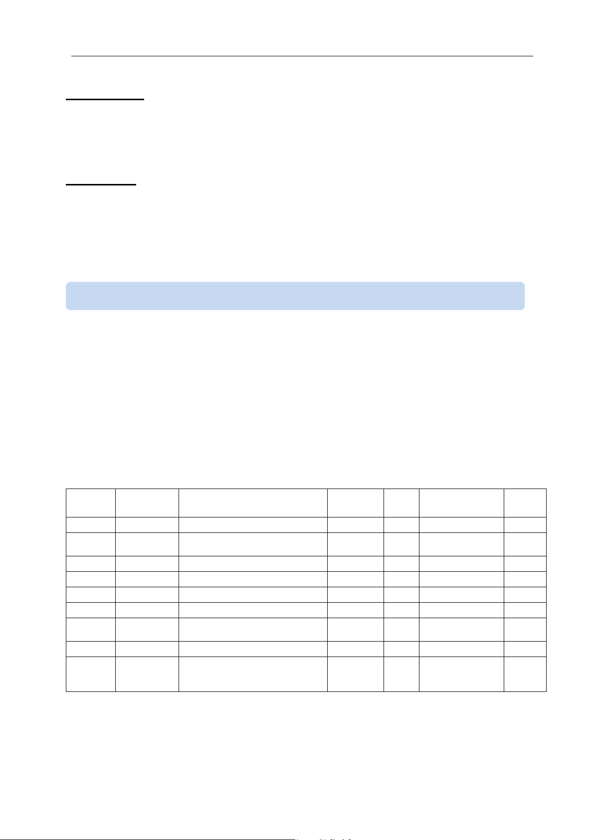
ADRESS NAME
7168 Password Programming password
7169
7170 Reset kWh Reset all kWh counters
7171 Reset Ah
7172 Reset hour Reset run counter
7173 Reset alarm Reset all alarms
7174
7175 Factory set Return to factory settings
7176 Boot mode
Reset
demand
Reset MinMax
DESCRIPTION
Reset all demand registers
Reset all Ah counters
Reset all min and max values
The unit switches to the boot
mode for firmware download
through USB.
LENGTH R/W
16 BIT
16 BIT
16 BIT
16 BIT
16 BIT
16 BIT
16 BIT
16 BIT
16 BIT W-O unsigned word 1
DATA TYPE COEFF
W-O unsigned word
W-O unsigned word
W-O unsigned word
W-O unsigned word
W-O unsigned word
W-O unsigned word
W-O unsigned word
W-O unsigned word
1
1
1
1
1
1
1
1
37
Page 38
DKM-250 User Manual V-2.0
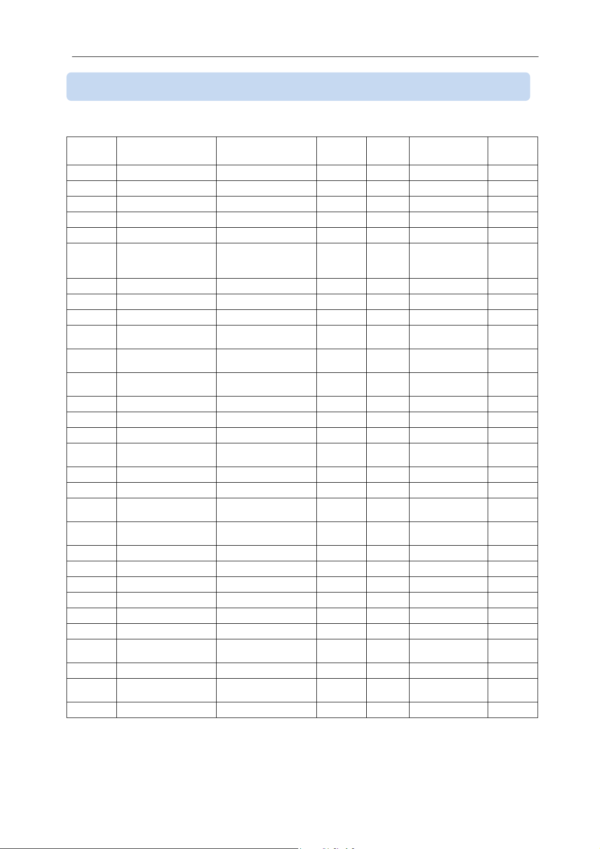
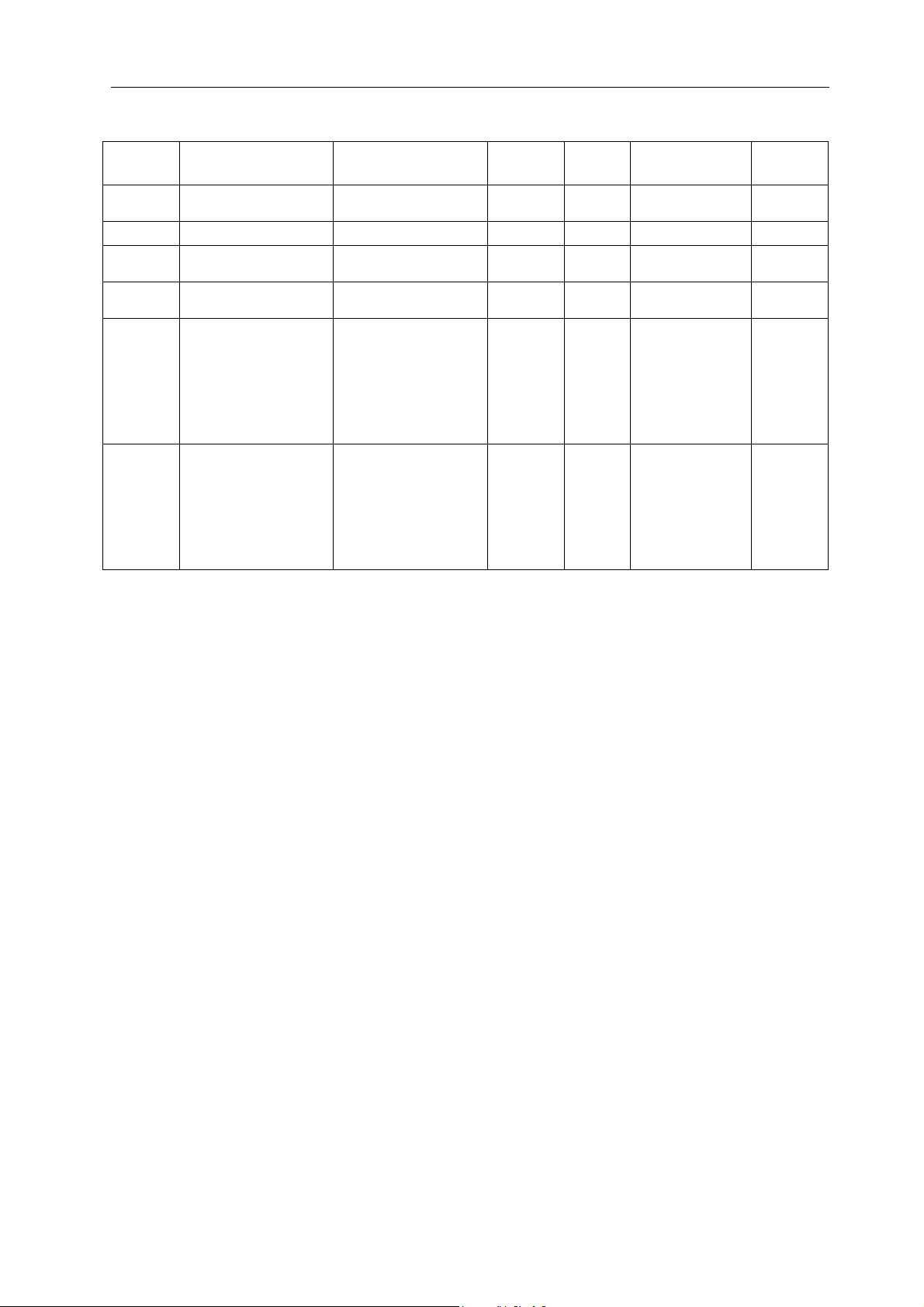
5.3. PROGRAM PARAMETERS
Program parameters of the unit may be read from below registers or program parameters may be set by
writing to these registers.
ADRESS NAME
01
02
03
04
05
06
07
08
09
10
11
12
13
14
15
16
17
18
19
20
21 Relay delay (sec) Explained ch 4.18 16 BIT
22 Relay-1 function
23 Relay-1 type
24 Relay-2 function
25 Relay-2 type
26 Digital input delay Explained ch 4.19 16 BIT
27
28 Digital input_1 type Explained ch 4.19 16 BIT
29
30 Digital input_2 type Explained ch 4.19 16 BIT
Shunt max current Explained ch 4.7
Shunt max voltage Explained ch 4.7
Overcurrent limit
Voltage high limit
Voltage low limit
Voltage input
selection (60V or
400V)
Power high limit
Power low limit
Demand periode
4-20mA Analog out
function selection
Analog out 4mA
value
Analog out 20mA
value
Default screen
Alarm delay
Alarm lock
Modbus node
address
Modbus baudrate
Modbus password Explained ch 4.16
Earth lekage %
upper limit (%)
Earth lekage %
lower limit (%)
Digital input_1
function
Digital input_2
function
DESCRIPTION
Explained ch 4.8
Explained ch 4.9
Explained ch 4.9
Explained ch 4.10
Explained ch 4.11
Explained ch 4.11
Explained ch 4.12
Explained ch 4.13
Explained ch 4.13
Explained ch 4.13
Explained ch 4.14
Explained ch 4.15
Explained ch 4.15
Explained ch 4.16
Explained ch 4.16
Explained ch 4.17 16 BIT
Explained ch 4.17 16 BIT
Explained ch 4.18
Explained ch 4.18
Explained ch 4.18
Explained ch 4.18
Explained ch 4.19 16 BIT
Explained ch 4.19 16 BIT
DIMENS R/W
16 BIT
16 BIT
16 BIT
16 BIT
16 BIT
16 BIT
16 BIT
16 BIT
16 BIT
16 BIT
16 BIT
16 BIT
16 BIT
16 BIT
16 BIT
16 BIT
16 BIT
16 BIT
16 BIT
16 BIT
16 BIT
16 BIT
R/W
R/W
R/W
R/W
R/W
R/W
R/W
R/W
R/W
R/W
R/W
R/W
R/W
R/W
R/W
R/W
R/W
R/W
R/W
R/W
R/W
R/W
R/W
R/W
R/W
R/W
R/W
R/W
R/W
R/W
DATA TYPE
signed word
signed word
signed word
signed word
signed word
signed word
signed word
signed word
signed word
signed word
signed word
signed word
signed word
signed word
signed word
signed word
signed word
signed word
unsigned word
unsigned word
unsigned word
unsigned word
unsigned word
unsigned word
unsigned word
unsigned word
unsigned word
unsigned word
unsigned word
unsigned word
COEFF
0.1
0.001
0.1
0.1
0.1
1
0.1
0.1
1
1
0.1
0.1
1
1
1
1
1
1
1
1
1
1
1
1
1
1
1
1
1
1
38
Page 39
DKM-250 User Manual V-2.0
ADRESS NAME
31
32 Pulse duration (sec) Explained ch 4.20 16 BIT
33
34
35
36
Counter increment
for 1 pulse
Min delay between
pulses
Counter selection
for pulses
Relay_1 control
through Modbus
Relay_2 control
through Modbus
DESCRIPTION
Explained ch 4.20 16 BIT
Explained ch 4.20 16 BIT
Explained ch 4.20 16 BIT
Explained in chapter
4.18 as relay
function 15.
If a value of 1234 is
written to this
address then the
relay will be active.
Explained in chapter
4.18 as relay
function 15.
If a value of 1234 is
written to this
address then the
relay will be active.
DIMENS R/W
R/W
R/W unsigned word 0.01
R/W unsigned word 0.01
R/W unsigned word 1
16 BIT
16 BIT
R/W unsigned word 1
R/W unsigned word 1
DATA TYPE
unsigned word
COEFF
0.001
39
Page 40
DKM-250 User Manual V-2.0
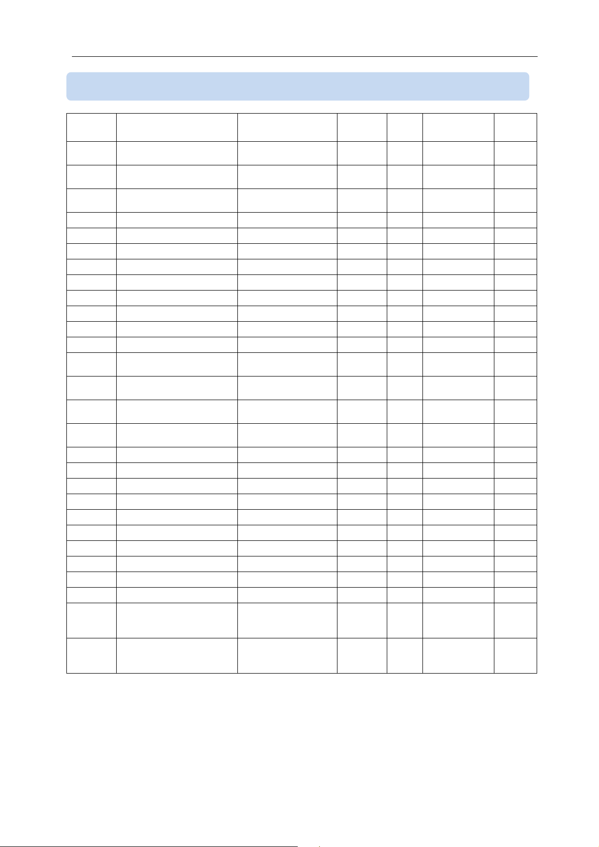
5.4. MEASUREMENTS AND CONTROLLER RECORDS
ADRESS NAME
8192
8194
8196
8198 Vin voltage
8200 Current (A)
8202 Power (kW)
8204 Voltage demand
8206 Positive current demand 32 BIT R-O unsigned long 0.01
8208 Negative current demand 32 BIT R-O signed long
8210 Positive power demand 32 BIT R-O unsigned long 0.001
8212 Negative power demand 32 BIT R-O signed long 0.001
8214 Max demand voltage
8216
8218
8220
8222
8224 Max voltage
8226 Min voltage
8228 Max current positive
8230 Min current positive
8232 Max power positive
8234 Min power positive
8236 Max current negative
8238 Min current negative
8240 Max power negative
8242 Min power negative
8244
8246
Voltage measured from
110V input
Voltage measured from
60V input
Voltage measured from
selected input
Max demand current
positive
Max demand current
negative
Max demand power
positive
Max demand power
negative
Current measured from
input-1 (normal scale,
large currents)
Current measured from
input-2 (sensitive scale,
small currents)
DESCRIPTION
32 BIT R-O unsigned long 0.01
32 BIT R-O unsigned long 0.01
32 BIT R-O unsigned long 0.01
32 BIT R-O signed long
32 BIT R-O signed long 0.001
32 BIT R-O unsigned long 0.01
DIMENS R/W DATA TYPE COEFF
32 BIT R-O unsigned long 0.01
32 BIT R-O unsigned long 0.01
32 BIT R-O unsigned long 0.01
32 BIT R-O signed long
32 BIT R-O unsigned long 0.001
32 BIT R-O signed long 0.001
32 BIT R-O unsigned long 0.01
32 BIT R-O unsigned long 0.01
32 BIT R-O unsigned long 0.01
32 BIT R-O unsigned long 0.01
32 BIT R-O unsigned long 0.001
32 BIT R-O unsigned long 0.001
32 BIT R-O signed long
32 BIT R-O signed long
32 BIT R-O signed long 0.001
32 BIT R-O signed long 0.001
32 BIT R-O signed long
32 BIT R-O signed long
0.01
0.01
0.01
0.01
0.01
0.01
0.01
40
Page 41
DKM-250 User Manual V-2.0
BIT
ADRESS NAME
8248
8240
8252 reserved 32 BIT R-O unsigned long 0.01
8254
8256
8258
8260
8262 Total run hour counter 32 BIT R-O unsigned long 0.1
8264 Alarms
8265 reserved
8266 Unit model
8267 Unit firmware version 16 BIT R-O
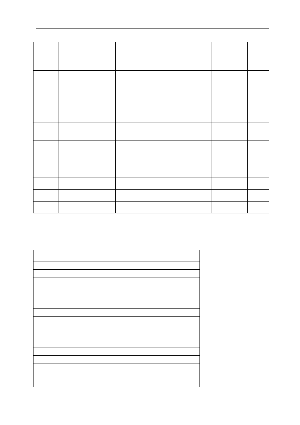
Alarm status record is 16 bit long. Each bit indicates the existence of one alarm.
NO:
DESCRIPTION
0
-
1
High voltage (Alarm 1)
2
Low voltage (Alarm 2)
3
Overcurrent (Alarm 3)
4
Excess power (kW) (Alarm 4)
5
Low power (kW) (Alarm 5)
6
Positive (+) Earth Leakage (Alarm 6)
7
Nega tive (-) Earth Leakage (Alarm 7)
8
-
9
-
10 -
11 -
12 -
13 -
14 -
15 -
Earth leakage voltage
(V)
Earth leakage percent
(%)
Energy counter (kWh),
positive direction
Energy counter (kWh),
negative direction
Ah (amperes*hour)
counter, positive
direction
Ah (amperes*hour)
counter, negative
direction
DESCRIPTION
32 BIT R-O unsigned long 0.01
32 BIT R-O unsigned long 0.01
32 BIT R-O unsigned long 0.1
32 BIT R-O unsigned long 0.1
32 BIT R-O unsigned long 0.1
32 BIT R-O unsigned long 0.1
Alarm durum kaydı
16 BIT R-O
16 BIT R-O
DIMENS R/W DATA TYPE COEFF
16 BIT R-O
unsigned
word
unsigned
word
unsigned
word
unsigned
word
41
1
1
1
0.1
Page 42

DKM-250 User Manual V-2.0
6. TECHNICAL SPECIFICATIONS
Supply Input: 19-150VDC
Power Consumption: < 4W
Voltage Measurements Inputs:
0-70V Input Sensitivity: 0.02V
70-150V Input Sensitivity: 0.40V
Current Measurement Input:
Measurement range: -100 to +100mV.
Accuracy: % 0.2
Isolation: 1000V AC, 1 minute
Internal Current Shunt Option:
Measurement range: 0-15A
Analog Output: 0-20mA
Analog Output Precision: 16 bit
Digital Input Range: 19 to 150VDC
Relay Outputs: 5 Amps @ 28VDC
Serial Port:
Signal type: RS-485
Protocol: Modbus RTU
Data Rate: 2400-38400baud
Isolation: 1000V AC, 1 minute
Operating Temp. Range: -20°C...+70 °C (-4°F...158°F)
Max. Relative Humidity: %95 non-condensing
Protection Degree: IP 65 (Front panel, w. gasket)
IP 30 (Back panel)
Enclosure: Flame retardent, ROHS compliant high temperature ABS/PC (UL94-V0)
Installation: Flush mounting with rear brackets
Dimensions: 102x102x53mm (WxHxD)
Panel Cutout: 92x92mm
Weight: 200 gr
EU Directives:
2014/35/EC (LVD)
2014/30/EC (EMC)
Tel: +90-216-466 84 60 Fax: +90-216-364 65 65 e-mail: [email protected] http: www.datakom.com.tr
Reference Standards:
EN 61010 (safety)
EN 61326 (EMC)
DATAKOM Elektronik Ltd.
42
 Loading...