


DKM-046 User Manual V-2.0
DESCRIPTION
FEATURES
DKM-046
TEMPERATURE &
HUMIDITY
CONTROLLER
DKM-046 is a DIN Rail mounted precision
unit capable of measuring temperature and
humidity in three different locations, provide
protection with 4 relay outputs and serve data
to remote monitoring and control systems.
Sensing modules are separated from the
base unit, connecting with cables. One
sensor comes together with the base unit.
Additional sensors may be purchased
separately.
Two different auxiliary supply versions are
available. The AC model accepts 85 to
305VAC and the DC model accepts 19 to
150VDC.
The module provides data to automation and
BMS systems through its isolated RS-485
Modbus port.
The programming is performed through
pushbuttons on the unit.
Sensor modules incorporate ST-HTS221
polymer dielectric planar capacitive sensors.
Relay functions are programmable with
functions selected from a list.
● Supports 3 temperature & humidity sensors
● AC and DC auxiliary supply versions
● Programmable relay outputs: 4
● Temperature and relative humidity control
● Independent cooling / heating / humidification
/ dehumidification functions for each sensor
● Temperature measuring range: -40...+80°C
● Humidity measuring range: 0% ... 100%
● Humidity accuracy: ±3.5% , 20 ... +80%
● Temperature accuracy: ± 1°C, 0 ... +60 °C
● Factory calibrated sensors
● Front panel programming
● Supports Modbus programming
● DIN rail mounted, easy installation
● Operating temp range: -20°C ... +70 °C
● Two part connection system
1

DKM-046 User Manual V-1.0
Electrical equipment should be installed only by qualified
specialist. No responsibility is assured by the manufacturer or
any of its subsidiaries for any consequences resulting from the
non-compliance to these instructions.
Check the unit for cracks and damages due to transportation.
Do not install damaged equipment.
Do not open the unit. There are no serviceable parts inside.
Fuses must be connected to the power supply inputs, in close
proximity of the unit.
Fuses must be of fast type with a maximum rating of 6A.
Disconnect all power before working on equipment.
When the unit is connected to the network do not touch
terminals.
Any electrical parameter applied to the device must be in the
range specified in the user manual. Although the unit is
designed with a wide safety margin, over-range parameters may
reduce lifetime, alter operational precision or even damage the
unit.
Do not try to clean the device with solvent or the like. Only
clean with a dump cloth.
Verify correct terminal connections before applying power.
SAFETY NOTICE
Failure to follow below instructions will result in
death or serious injury
2

DKM-046 User Manual V-1.0
TABLE OF CONTENTS
Section
1. INSTALLATION INSTRUCTIONS
1.1 FRONT PANEL VIEW
1.2 ELECTRICAL INSTALLATION
1.3 INSTALLATION DIAGRAM
2. PUSHBUTTON FUNCTIONS
3. SCREEN NAVIGATION
3.1 LAMP TEST
4. PROGRAMMING
4.1 ENTERING THE PROGRAMMING MODE
4.2 RESETTING ALARMS
4.3 SELECTING THE DEFAULT SCREEN
4.4 ADJUSTING TEMPERATURE LOW AND HIGH LIMITS
4.5 ADJUSTING RELATIVE HUMIDITY LOW AND HIGH LIMITS
4.6 ENABLING / DISABLING SENSORS
4.7 CONFIGURING RELAY OUTPUTS
4.8 ALARM DELAY
4.9 ALARM LOACK
4.10 MODBUS PARAMETERS
4.11 ADJUSTING TEMPERATURE OFFSET VALUES
4.12 ADJUSTING RELATIVE HUMIDITY OFFSET VALUES
4.13 ADJUSTING TEMPERATURE DIFFERENCE ALARM LIMITS
4.14 ADJUSTING COOLING START TEMPERATURE UPPER LIMITS
4.15 ADJUSTING HEATING START TEMPERATURE LOW LIMITS
4.16 ADJUSTING TEMPERATURE HYSTERESIS FOR COOLING AND
HEATING
4.17 ADJUSTING DE-HUMIDIFICATION START HUMIDITY
4.18 ADJUSTING HUMIDIFICATION START HUMIDITY
4.19 ADJUSTING HUMIDITY HYSTERESIS FOR HUMIDIFICATION
AND DE-HUMIDIFICATION
4.20 DISPLAYING THE FIRMWARE VERSION
4.21 RETURN TO FACTORY SETTINGS
3

DKM-046 User Manual V-1.0
5. MODBUS COMMUNICATIONS
5.1. DESCRIPTION
5.2. COMMANDS
5.3. PROGRAM PARAMETERS
5.4. MEASUREMENTS AND CONTROLLER RECORDS
6. TECHNICAL SPECIFICATIONS
4

DKM-046 User Manual V-1.0
1. INSTALLATION INSTRUCTIONS
Before installation:
Read the user manual carefully, determine the correct connection diagram.
Install the unit to the DIN rail.
Make electrical connections with plugs removed from sockets, then place plugs to their sockets.
Be sure that adequate cooling is provided.
Be sure that the temperature of the environment will not exceed the maximum operating temperature in any
case.
Be sure that the unit is not subject to water spill.
Below conditions may damage the device:
Incorrect connections.
Incorrect power supply voltage.
Connecting or removing data terminals when the unit is powered-up.
Connecting or removing sensors when the unit is powered-up.
High voltage applied to communication ports.
Overload or short-circuit at relay outputs.
Excessive vibration, direct installation on vibrating parts.
Below conditions may cause abnormal operation:
Power supply voltage below minimum acceptable level.
Power supply frequency outside acceptable limits.
5

DKM-046 User Manual V-1.0
1.1 FRONT PANEL VIEW
6

DKM-046 User Manual V-1.0
Do not install the unit close to high electromagnetic
noise emitting devices like contactors, high current
busbars, switchmode power supplies and the like.
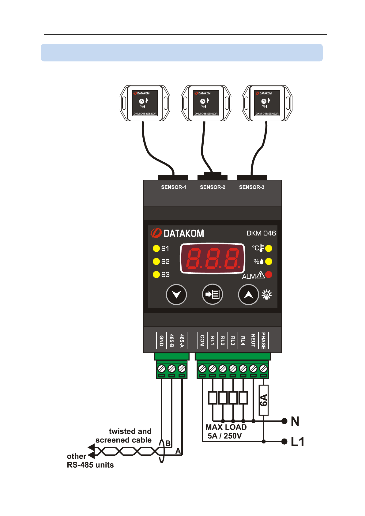
1.2 ELECTRICAL INSTALLATION
Although the unit is protected against electromagnetic disturbance, excessive disturbance
can affect the operation, measurement precision and data communication quality.
ALWAYS remove plug connectors when inserting wires with a screwdriver.
Fuses must be connected to the power supply inputs, in close proximity of the unit.
Fuses must be of fast type with a maximum rating of 6A.
Use cables of appropriate temperature range.
Use adequate cable section, at least 0.75mm2 (AWG18).
Follow national rules for electrical installation.
7
DKM-046 User Manual V-1.0
1.3 INSTALLATION DIAGRAM
8

DKM-046 User Manual V-1.0
BUTTON
FUNCTION
PROGRAMMING: Select related parameter / save adjusted
parameter.
Switch to the upper screen.
PROGRAMMING: increase value
Switch to the lower screen.
PROGRAMMING: decrease value
HELD PRESSED TOGETHER FOR 2 SECONDS:
Selects programming mode. If held pressed in programming
mode, then returns to normal mode.
NO KEY PRESSED DURING 1 MINUTE:
Returns to the main display screen.
2. PUSHBUTTON FUNCTIONS
9
DKM-046 User Manual V-1.0
HELD PRESSED FOR 2 SECONDS:
Enters lamp test mode. When released returns to
normal operating mode.
3.1 LAMP TEST
3. SCREEN NAVIGATION
Buttons allow navigation between measurement values. (Temp_1, Humidity_1,
Temp_2, Humidity_2, Temp_3, Humidity_3, Alarms)
Leds related to the currently displayed values will turn on, other leds will turn off.
Temperature display: Temperature is displayed with 0.1 °C accuracy. The related Modbus
register has 0.01 °C accuracy.
Humidity display: The relative humidity is displayed with 1% accuracy. The related
Modbus register has 0.01% accuracy.
10
DKM-046 User Manual V-1.0
In order to enable the programming menu,
hold both MENU buttons pressed for 2 seconds.
In order to exit programming menu,
hold both MENU buttons pressed for 2 seconds.
If no button is pressed during 1 minute, then the unit will
automatically close the programming mode.
Parameters may be scrolled with these buttons.
When SET button is pressed:
The parameter value is displayed
The value on the screen is recorded and the next
parameter is displayed.
Parameter values are modified with UP and DOWN Menu
buttons. If the button is held pressed, the the value will change
with larger steps.
After adjusting the parameter value this button saves the value
on the screen and switched to the next parameter.
4. PROGRAMMING
4.1 ENTERING THE PROGRAMMING MODE
In order to offer the maximum flexibility to the customer, the module has several
programmable parameters.
Device configurations
Default screen configuration
Measurement configurations
Alarm reset
Alarm high/low limit adjustments
Input/Output Configurations
Relay configuration
Alarm delays
Modbus configuration
Unit Calibration
Modbus configuration
Return to factory settings
11

DKM-046 User Manual V-1.0
Parameter value:
0: No operation
1: Reset alarms
Setting this parameter to 1 causes alarms to be reset.
The parameter value is not saved and always reads 0.
The description of alarm codes visible on the screen are below:
Alarm Code
Description
AL1
Sensor-1 low temperature
AL2
Sensor-1 high temperature
AL3
Sensor-1 low relative humidity
AL4
Sensor-1 high relative humidity
AL5
Sensor-2 low temperature
AL6
Sensor-2 high temperature
AL7
Sensor-2 low relative humidity
AL8
Sensor-2 high relative humidity
AL 9
Sensor-3 low temperature
A10
Sensor-3 high temperature
A11
Sensor-3 low relative humidity
A12
Sensor-3 high relative humidity
A13
T1-T2 or T2-T1 temperature difference alarm
A14
T2-T3 or T3-T2 temperature difference alarm
A15
T3-T1 or T1-T3 temperature difference alarm
This parameter selects the screen menu where the unit returns
when no pushbutton is pressed during 1 minutes.
Param.
değeri
Ekran
0
Auto-scroll screens
1
Temperature_1 measurement
2
Humidity_1 measurement
3
Temperature_2 measurement
4
Humidity_2 measurement
5
Temperature_3 measurement
6
Humidity_3 measurement
4.3 SELECTING THE DEFAULT SCREEN
4.2 RESETTING ALARMS
When an alarm occurs, the display switches automatically to alarm display mode. If any key
is pressed then it resumes normal operation.
12

DKM-046 User Manual V-1.0
These parameters adjust the low temperature alarm limit for the
related sensor.
Adjustment range is between -20°C and +80°C.
If the parameter is set to -20°C then low temperature alarm is
not monitored for the related sensor.
As the default factory set, the alarm is passive.
These parameters adjust the high temperature alarm limit for
the related sensor.
Adjustment range is between -20°C and +80°C.
If the parameter is set to +80°C then high temperature alarm is
not monitored for the related sensor.
As the default factory set, the alarm is passive.
These parameters adjust the low relative humidity alarm limit for
the related sensor.
Adjustment range is between 1% and 99%.
If the parameter is set to 1% then low relative humudity alarm is
not monitored for the related sensor.
As the default factory set, the alarm is passive.
These parameters adjust the high relative humidity alarm limit
for the related sensor.
Adjustment range is between 1% and 99%.
If the parameter is set to 99% then high relative humudity alarm
is not monitored for the related sensor.
As the default factory set, the alarm is passive.
4.5 ADJUSTING RELATIVE HUMIDITY LOW AND HIGH LIMITS
4.4 ADJUSTING TEMPERATURE LOW AND HIGH LIMITS
13

DKM-046 User Manual V-1.0
Parameter value:
0: Sensor disabled
1: Sensor enabled
These parameters enable/disable sensors 2 and 3.
The factory set value is 0 (sensor disabled).
When a sensor is disabled, the temperature and relative alarm
limits related to this sensor cannot be adjusted.
Sensor 1 cannot be disabled. It is always active.
4.6 ENABLING / DISABLING SENSORS
14

DKM-046 User Manual V-1.0
The unit provides 4 relay outputs. Each output reflects the
combination of 4 different relay functions. The combination
options are explained in the next parameter.
The total number of relay functions are 16. They are presented
as in the picture at left.
As an examle, 1r4 means function_4 of relay_1, 3r2 means
function_2 of relay_3.
Unused funtions should be left as 0.
Value
Relay Function
0
-
1
Sensor-1 low temperature
2
Sensor-1 high temperature
3
Sensor-1 low relative humidity
4
Sensor-1 high relative humidity
5
Sensor-2 low temperature
6
Sensor-2 high temperature
7
Sensor-2 low relative humidity
8
Sensor-2 high relative humidity
9
Sensor-3 low temperature
10
Sensor-3 high temperature
11
Sensor-3 low relative humidity
12
Sensor-3 high relative humidity
13
Function active if any alarm exists
14
Through Modbus registers:
If any non-zero value is written in related
register, then the function is active.
Relay-1: address 48
Relay-2: address 49
Relay-3: address 50
Relay-4: address 51
15
T1-T2 temperature difference alarm
16
T2-T3 temperature difference alarm
17
T3-T1 temperature difference alarm
18
T1 temperature cooling active
19
T1 temperature heating active
20
H1 sensor de-humidification active
21
H1 sensor humidification active
22
T2 temperature cooling active
23
T2 temperature heating active
24
H2 sensor de-humidification active
25
H2 sensor humidification active
26
T3 temperature cooling active
27
T3 temperature heating active
28
H3 sensor de-humidification active
29
H3 sensor humidification active
4.7 CONFIGURING RELAY OUTPUTS
15

DKM-046 User Manual V-1.0
The factory set value for all relay functions is 0.
The adjustment range is from 0 to 14.
Each relay output is activated by the combination of 4 different
functions as explained above. Thus relay may be assigned to
complex functions.
Parameters at left adjust the function combination method for
each relay output.
0: Functions are combined with logical OR operation. Thus if
any of the function is active, then the relay output is active.
1: Functions are combined with logical AND operation. Thus the
relay output will be active only if all functions are active.
This parameter adjusts the delay for relay activation after all
conditions for relay operation are met.
The factory set value is 0.
Adjustment range is between 0 and 999 seconds.
This parameter adjusts the delay for alarm activation after an
alarm condition occurs. It also determines the delay for alarm
deactivation after the alarm condition is removed.
The factory set value is 0.
Adjustment range is between 0 and 999 seconds.
4.8 ALARM DELAY
16

DKM-046 User Manual V-1.0
0: Alarm lock disabled
1: Alarm lock enabled
When this parameter is set to 1, even if the alarm cause is
removed, alarms will persist until manually reset.
When this parameter is set to 0, when the alarm cause is
removed, alarms automatically disappear.
Factory set value is 0.
Adjustment range is 0 to 1.
This parameter determines the Modbus node address of the
unit. Every unit in the same Modbus loop must have a different
node address.
Factory set value is 1.
Adjustment range is 0 to 255.
This parameter determines the data rate (baud rate) used in the
Modbus communication. Every unit in the same Modbus loop
must use the same data rate.
0: Baud rate = 2400
1: Baud rate = 4800
2: Baud rate = 9600
3: Baud rate = 19200
4: Baud rate = 38400
5: Baud rate = 57600
6: Baud rate = 115200
Factory set value is 2.
Adjustment range is 0 to 6.
4.9 ALARM LOCK
4.10 MODBUS PARAMETERS
17

DKM-046 User Manual V-1.0
These parameters determine respectively the offset value to be
added to temperature sensors 1, 2 and 3.
Factory set value is 0.
Adjustment range is between – 9.9 and + 9.9 °C.
These parameters determine respectively the offset value to be
added to relative humidity sensors 1, 2 and 3.
Factory set value is 0.
Adjustment range is between – 9.9% and + 9.9%.
4.11 ADJUSTING TEMPERATURE OFFSET VALUES
4.12 ADJUSTING RELATIVE HUMIDITY OFFSET VALUES
18

DKM-046 User Manual V-1.0
These parameters determine respectively the high alarm limits
for temperature differences T1-T2, T2-T1, T2-T3, T3-T2, T3-T1,
T1-T3.
Adjustment range is between 0°C and 100°C.
Factory set value is 0 and the alarm is passive.
When this parameter is set to 0, the temperature difference
alarm is de-activated.
These parameters determine respectively the cooling start
upper limits for temperature sensors 1 , 2 and 3.
When the temperaure measured from the related sensor goes
over the programmed limit, then the cooling relay function will
become active. When the measured temperature goes below
the limit more than the programmed hysteresis value, then the
cooling relay function will become passive.
Adjustment range is between -21°C and +80°C.
Factory set value is +40°C.
4.14 ADJUSTING COOLING START TEMPERATURE UPPER LIMITS
4.13 ADJUSTING TEMPERATURE DIFFERENCE ALARM LIMITS
19

DKM-046 User Manual V-1.0
These parameters determine respectively the heating start
temperature limits for temperature sensors 1 , 2 and 3.
When the temperaure measured from the related sensor goes
below the programmed limit, then the heating relay function will
become active. When the measured temperature goes above
the limit more than the programmed hysteresis value, then the
heating relay function will become passive.
Adjustment range is between -21°C and +80°C.
Factory set value is +20°C.
These parameters determine respectively the hysteresis values
for stopping the heating or cooling for temperature sensors 1 , 2
and 3.
Adjustment range is between 0°C and 100°C.
Factory set value is 5°C.
These parameters determine respectively the de-humidification
start upper limits for humidity sensors 1 , 2 and 3.
When the relative humidity measured from the related sensor
goes over the programmed limit, then the de-humidification
relay function will become active. When the measured relative
humidity goes below the limit more than the programmed
hysteresis value, then the de-humidification relay function will
become passive.
Adjustment range is between 0% and +100%
Factory set value is 70%.
4.17 ADJUSTING DE-HUMIDIFICATION START HUMIDITY
4.16 ADJUSTING TEMPERATURE HYSTERESIS FOR COOLING
AND HEATING
4.15 ADJUSTING HEATING START TEMPERATURE LOW LIMITS
20

DKM-046 User Manual V-1.0
These parameters determine respectively the humidification
start lower limits for humidity sensors 1 , 2 and 3.
When the relative humidity measured from the related sensor
goes below the programmed limit, then the humidification relay
function will become active. When the measured relative
humidity goes above the limit more than the programmed
hysteresis value, then the humidification relay function will
become passive.
Adjustment range is between 0% and +100%
Factory set value is 30%.
These parameters determine respectively the hysteresis values
for stopping the humidification/de-humidification for humidity
sensors 1 , 2 and 3.
Adjustment range is between 0% and 100%.
Factory set value is 5%.
The firmware version is displayed in the PGv (program version)
parameter.
It cannot be modified by the user.
Any inquiry to the manufacturer must state the firmware version
in question.
4.19 ADJUSTING HUMIDITY HYSTERESIS FOR HUMIDIFICATION
AND DE-HUMIDIFICATION
4.18 ADJUSTING HUMIDIFICATION START HUMIDITY
4.20 DISPLAYING THE FIRMWARE VERSION
21

DKM-046 User Manual V-1.0
Parameter value:
57: return to factory settings
Other values: No operation
Setting this parameter to 57 causes the unit to return to initial
factory settings.
The parameter value is not recorded and always reads as 0.
4.21 RETURN TO FACTORY SETTINGS
22

DKM-046 User Manual V-1.0
Byte
Description
Value
0
Controller address
1 to 254
1
Function code
3 2 Starting address high
See below the description of available
registers
3
Starting address low
4
Number of registers high
always 0
5
Number of registers low
max 78h (120 decimal)
6
CRC low byte
See below for the checksum calculation
7
CRC high byte
5. MODBUS COMMUNICATIONS
5.1. DESCRIPTION
The unit offers serial data communication port allowing it to be integrated in automation
systems.
The serial port is of RS-485 MODBUS-RTU standard. It is fully isolated from power supply
and measurement terminals for failure-free operation under harsh industrial conditions.
The MODBUS properties of the unit are:
-Data transfer mode: RTU
-Serial data: 2400-115200 bps, 8 bit data, no parity, 1 bit stop
-Supported functions:
-Function 3 (Read multiple registers)
-Function 6 (Write single register)
-Function 10 (Write multiple register)
-The answer to an incoming message is sent with a minimum of 4.3ms delay after
message reception.
Each register consists of 2 bytes (16 bits). Larger data structure contain multiple registers.
Detailed description about the MODBUS protocol is found in the document “Modicon
Modbus Protocol Reference Guide”. This document may be downloaded at:
http://www.modbus.org/specs.php
Data Reading
The function 03 (read multiple registers) will be used for data reading. The MODBUS
master will send a query. The answer will be one of the below:
-A response containing the requested data
-An exceptional response indicating a read error.
The maximum number of registers read in one message is 120. If more registers are
requested, the unit will send only the first 120 registers.
The query message specifies the starting register and quantity of registers to be read. The
message structure is below:
Here is the sequence to read 16 registers starting from address 20h (32 decimal):
01 03 00 20 00 10 45 CC (each byte is expressed as 2 hexadecimal characters)
The checksum value in the above message may be used for the verification of checksum
calculation algorithm.
23

DKM-046 User Manual V-1.0
Byte
Description
Value
0
Controller address
same as in the query
1
Function code
3 2 Data lenght in bytes (L)
number of registers * 2
3
High byte of 1st register
4 Low byte of 1st register
5 High byte of 2nd register
6 Low byte of 2nd register
....
L+1
High byte of the last register
L+2
Low byte of the last register
L+3
CRC low byte
See below for the checksum calculation
L+4
CRC high byte
Byte
Description
Value
0
Controller address
same as in the query
1
Function code
131 (function code + 128)
2
Exception code
2 (illegal address)
3
CRC low byte
See below for the checksum calculation
4
CRC high byte
Byte
Description
Value
0
Controller address
1 to 254
1
Function code
6 2 Register address high
See below the description of available registers
3
Register address low
4
Data high byte
5
Data low byte
6
CRC low byte
See below for the checksum calculation
7
CRC high byte
The normal response will be:
The exceptional response will be:
Data Writing
The function 06 (write single register) or function 10h (write multiple registers) is used for
data writing. A maximum of 32 registers can be written at a time.
The MODBUS master will send a query containing data to be written. The answer will be
one of the below:
-A normal response confirming successful write,
-An exceptional response indicating a write error.
Only some of the available registers are authorized to be written. An attempt to write a write
protected register will result to the exceptional response.
The query message specifies the register address and data. The message structure is
below:
24

DKM-046 User Manual V-1.0
Byte
Description
Value
0
Controller address
1 to 254
1
Function code
6 2 Register address high
See below the description of available registers
3
Register address low
4
Data high byte
5
Data low byte
6
CRC low byte
See below for the checksum calculation
7
CRC high byte
Byte
Description
Value
0
Controller address
same as in the query
1
Function code
134 (function code + 128)
2
Exception code
2 (illegal address)
or
10 (write protection)
3
CRC low byte
See below for the checksum calculation
4
CRC high byte
Here is the sequence to write the value 0010h to the register 40h (64 decimal):
01 06 00 40 00 10 89 D2 (each byte is expressed as 2 hexadecimal characters)
The checksum value in the above message may be used for the verification of checksum
calculation algorithm
The normal response will be the same as the query:
The exceptional response will be:
CRC calculation
Here is a procedure for generating a CRC:
1) Load a 16–bit register with FFFF hex (all 1’s). Call this the CRC register.
2) Exclusive OR the first 8–bit byte of the message (the function code byte) with the low–
order byte of the 16–bit CRC register, putting the result in the CRC register.
3) Shift the CRC register one bit to the right (toward the LSB), zero–filling the MSB. Extract
and examine the LSB. The LSB is the least significant bit of the CRC before the shift
operation.
4) If the LSB is 1: Exclusive OR the CRC register with the polynomial value A001 hex.
5) Repeat Steps 3 and 4 until 8 shifts have been performed. Thus, a complete 8–bit byte
will be processed.
6) Repeat Steps 2 through 5 for the next 8–bit byte of the message. Continue doing this
until all bytes have been processed.
7) The final contents of the CRC register is the CRC value.
8) Place the CRC into the message such that the low byte is transmitted first. The algorithm
should give the correct CRC for below messages:
01 03 00 20 00 10 45 CC
01 06 00 40 00 10 89 D2
25

DKM-046 User Manual V-1.0
ADDRESS
NAME
DESCRIPTION
LENGTH
R/W
DATA TYPE
COEFF
16384
Password
Programming password
16 BIT
W-O
unsigned word
1
16385
Reset alarms
Reset all existing alarms
16 BIT
W-O
unsigned word
1
16386
Factory set
Return to factory settings
16 BIT
W-O
unsigned word
1
5.2. COMMANDS
Error codes
Only 3 error codes are used:
01: illegal function code
02: illegal address
10: write protection (attempt to write a read_only register)
Data types
Each register consists of 16 bits (2 bytes)
If the data type is a byte, only the low byte will contain valid data. High byte is don’t care.
For data type longer than 16 bits, consecutive registers are used. The least significant
register comes first.
Commands to the unit are written to below addresses.
If addresses 76 and 77 are left as in the factory setting (value=0) then the the unit will not
ask any password for Modbus commands and Modbus writes.
If any non-zero value is written to register 77, then the unit will require password for
Modbus reads and Modbus writes. If any non-zero value is written to register 76, then the
unit will require password for Modbus reads.
If the value recorded to one of the registers 76 or 77, or 3271 or 3282 is written to the
address 16384, then during next 10 minutes, Modbus area can be written and below
commands can be executed.
All commands (other than the password) may be activated by writing a non-zero value to
the related register.
26

DKM-046 User Manual V-1.0
ADRESS
NAME
DESCRIPTION
DIMENS
R/W
DATA TYPE
COEFF
01
Default screen
Explained ch 4.3
16 BIT
R/W
unsigned word
1
02
Sensor-1 low temp
Explained ch 4.4
16 BIT
R/W
signed word
1
03
Sensor-1 high temp
Explained ch 4.4
16 BIT
R/W
signed word
1
04
Sensor-1 low humid.
Explained ch 4.5
16 BIT
R/W
unsigned word
1
05
Sensor-1 high hum.
Explained ch 4.5
16 BIT
R/W
unsigned word
1
06
Sensor-2 enable
Explained ch 4.6
16 BIT
R/W
unsigned word
1
07
Sensor-2 low temp
Explained ch 4.4
16 BIT
R/W
signed word
1
08
Sensor-2 high temp
Explained ch 4.4
16 BIT
R/W
signed word
1
09
Sensor-2 low humid.
Explained ch 4.5
16 BIT
R/W
unsigned word
1
10
Sensor-2 high hum.
Explained ch 4.5
16 BIT
R/W
unsigned word
1
11
Sensor-3 enable
Explained ch 4.6
16 BIT
R/W
unsigned word
1
12
Sensor-2 low temp
Explained ch 4.4
16 BIT
R/W
signed word
1
13
Sensor-2 high temp
Explained ch 4.4
16 BIT
R/W
signed word
1
14
Sensor-2 low humid.
Explained ch 4.5
16 BIT
R/W
unsigned word
1
15
Sensor-2 high hum.
Explained ch 4.5
16 BIT
R/W
unsigned word
1
16
Relay-1, function-1
Explained ch 4.7
16 BIT
R/W
unsigned word
1
17
Relay-1, function-2
Explained ch 4.7
16 BIT
R/W
unsigned word
1
18
Relay-1, function-3
Explained ch 4.7
16 BIT
R/W
unsigned word
1
19
Relay-1, function-4
Explained ch 4.7
16 BIT
R/W
unsigned word
1
20
Relay-1 logic
Explained ch 4.7
16 BIT
R/W
unsigned word
1
21
Relay-2, function-1
Explained ch 4.7
16 BIT
R/W
unsigned word
1
22
Relay-2, function-2
Explained ch 4.7
16 BIT
R/W
unsigned word
1
23
Relay-2, function-3
Explained ch 4.7
16 BIT
R/W
unsigned word
1
24
Relay-2, function-4
Explained ch 4.7
16 BIT
R/W
unsigned word
1
25
Relay-2 logic
Explained ch 4.7
16 BIT
R/W
unsigned word
1
26
Relay-3, function-1
Explained ch 4.7
16 BIT
R/W
unsigned word
1
27
Relay-3, function-2
Explained ch 4.7
16 BIT
R/W
unsigned word
1
28
Relay-3, function-3
Explained ch 4.7
16 BIT
R/W
unsigned word
1
29
Relay-3, function-4
Explained ch 4.7
16 BIT
R/W
unsigned word
1
30
Relay-3 logic
Explained ch 4.7
16 BIT
R/W
unsigned word
1
31
Relay-4, function-1
Explained ch 4.7
16 BIT
R/W
unsigned word
1
32
Relay-4, function-2
Explained ch 4.7
16 BIT
R/W
unsigned word
1
33
Relay-4, function-3
Explained ch 4.7
16 BIT
R/W
unsigned word
1
34
Relay-4, function-4
Explained ch 4.7
16 BIT
R/W
unsigned word
1
35
Relay-4 logic
Explained ch 4.7
16 BIT
R/W
unsigned word
1
36
Relay delay
Explained ch 4.7
16 BIT
R/W
unsigned word
1
37
Alarm delay
Explained ch 4.8
16 BIT
R/W
unsigned word
1
38
Alarm lock
Explained ch 4.9
16 BIT
R/W
unsigned word
1
5.3. PROGRAM PARAMETERS
Program parameters of the unit may be read from below registers or program parameters may be set by
writing to these registers.
27

DKM-046 User Manual V-1.0
ADRESS
NAME
DESCRIPTION
DIMENS
R/W
DATA TYPE
COEFF
39
Modbus node
address
Explained ch 4.10
16 BIT
R/W
unsigned word
1
40
Modbus baudrate
Explained ch 4.10
16 BIT
R/W
unsigned word
1
41
Sensor-1, temp
offset
Explained ch 4.11
16 BIT
R/W
signed word
0.1
42
Sensor-1, humidity
offset
Explained ch 4.12
16 BIT
R/W
signed word
0.1
43
Sensor-2, temp
offset
Explained ch 4.11
16 BIT
R/W
signed word
0.1
44
Sensor-2, humidity
offset
Explained ch 4.12
16 BIT
R/W
signed word
0.1
45
Sensor-3, temp
offset
Explained ch 4.11
16 BIT
R/W
signed word
0.1
46
Sensor-3, humidity
offset
Explained ch 4.12
16 BIT
R/W
signed word
0.1
47
T1-T2 temp. diff.
alarm limit
Explained ch 4.13
16 BIT
R/W
unsigned word
1
48
T2-T1 temp. diff.
alarm limit
Explained ch 4.13
16 BIT
R/W
unsigned word
1
49
T2-T3 temp. diff.
alarm limit
Explained ch 4.13.
16 BIT
R/W
unsigned word
1
50
T3-T2 temp. diff.
alarm limit
Explained ch 4.13
16 BIT
R/W
unsigned word
1
51
T3-T1 temp. diff.
alarm limit
Explained ch 4.13
16 BIT
R/W
unsigned word
1
52
T1-T3 temp. diff.
alarm limit
Explained ch 4.13.
16 BIT
R/W
unsigned word
1
53
T1 cooling start
temperature
Explained ch 4.14
16 BIT
R/W
signed word
1
54
T1 heating start
temperature
Explained ch 4.15
16 BIT
R/W
signed word
1
55
T1 cooling and
heating hysteresis
temperature
Explained ch 4.16
16 BIT
R/W
unsigned word
1
56
H1 de-humidification
start RH
Explained ch 4.17
16 BIT
R/W
unsigned word
1
57
H1 humidification
start RH
Explained ch 4.18
16 BIT
R/W
unsigned word
1
58
H1 hysteresis RH
Explained ch 4.19
16 BIT
R/W
unsigned word
1
59
T2 cooling start
temperature
Explained ch 4.14
16 BIT
R/W
signed word
1
60
T2 heating start
temperature
Explained ch 4.15
16 BIT
R/W
signed word
1
61
T2 cooling and
heating hysteresis
temperature
Explained ch 4.16
16 BIT
R/W
unsigned word
1
62
H2 de-humidification
start RH
Explained ch 4.17
16 BIT
R/W
unsigned word
1
63
H2 humidification
start RH
Explained ch 4.18
16 BIT
R/W
unsigned word
1
64
H2 hysteresis RH
Explained ch 4.19
16 BIT
R/W
unsigned word
1
28

DKM-046 User Manual V-1.0
ADRESS
NAME
DESCRIPTION
DIMENS
R/W
DATA TYPE
CO
EFF
65
T3 cooling start
temperature
Explained ch 4.14
16 BIT
R/W
signed word
1
66
T3 heating start
temperature
Explained ch 4.15
16 BIT
R/W
signed word
1
67
T3 cooling and
heating
hysteresis
temperature
Explained ch 4.16
16 BIT
R/W
unsigned word
1
68
H3 dehumidification
start RH
Explained ch 4.17
16 BIT
R/W
unsigned word
1
69
H3 humidification
start RH
Explained ch 4.18
16 BIT
R/W
unsigned word
1
70
H3 hysteresis RH
Explained ch 4.19
16 BIT
R/W
unsigned word
1
71
Software version
Explained ch 4.13
16 BIT
R/W
unsigned word
1
72
Modbus relay-1
Explained ch 4.17
If the relay function is selected
as 14 and any non-zero value
is written to this register, then
the relay function for the
related relay will be active.
16 BIT
R/W
unsigned word
1
73
Modbus relay-2
Explained ch 4.17
If the relay function is selected
as 14 and any non-zero value
is written to this register, then
the relay function for the
related relay will be active.
16 BIT
R/W
unsigned word
1
74
Modbus relay-3
Explained ch 4.17
If the relay function is selected
as 14 and any non-zero value
is written to this register, then
the relay function for the
related relay will be active.
16 BIT
R/W
unsigned word
1
75
Modbus relay-4
Explained ch 4.17
If the relay function is selected
as 14 and any non-zero value
is written to this register, then
the relay function for the
related relay will be active.
16 BIT
R/W
unsigned word
1
76
Modbus read
password
Explained ch 5.2
16 BIT
R/W
unsigned word
1
77
Modbus write
password
Explained ch 5.2
16 BIT
R/W
unsigned word
1
29

DKM-046 User Manual V-1.0
ADRESS
NAME
DESCRIPTION
DIMENS
R/W
DATA TYPE
COEFF
78
Sensor-1,
temperature
calibration
The factory set value is
256. The measured
value is multiplied with
this register and divided
by 256 before
displaying.
16 BIT
R/W
unsigned word
1
79
Sensor-1, humidity
calibration
The factory set value is
256. The measured
value is multiplied with
this register and divided
by 256 before
displaying.
16 BIT
R/W
unsigned word
1
80
Sensor-2,
temperature
calibration
The factory set value is
256. The measured
value is multiplied with
this register and divided
by 256 before
displaying.
16 BIT
R/W
unsigned word
1
81
Sensor-2, humidity
calibration
The factory set value is
256. The measured
value is multiplied with
this register and divided
by 256 before
displaying.
16 BIT
R/W
unsigned word
1
82
Sensor-3,
temperature
calibration
The factory set value is
256. The measured
value is multiplied with
this register and divided
by 256 before
displaying.
16 BIT
R/W
unsigned word
1
83
Sensor-3, humidity
calibration
The factory set value is
256. The measured
value is multiplied with
this register and divided
by 256 before
displaying.
16 BIT
R/W
unsigned word
1
30

DKM-046 User Manual V-1.0
ADDR
ESS
NAME
DESCRIPTION
DIMENS
R/W
DATA TYPE
COEFFI
10609
Unit ID
Unit model type
16 BIT
R-O
unsigned word
1
20480
Sensor-1
temperature
16 BIT
R-O
signed word
0.01
20481
Sensor-1 relative
humidity
16 BIT
R-O
unsigned word
0.01
20482
Sensor-2
temperature
16 BIT
R-O
signed word
0.01
20483
Sensor-2 relative
humidity
16 BIT
R-O
unsigned word
0.01
20484
Sensor-3
temperature
16 BIT
R-O
signed word
0.01
20485
Sensor-3 relative
humidity
16 BIT
R-O
unsigned word
0.01
20486
Alarms
Alarm status bits
16 BIT
R-O
unsigned word
1
20487
Relay statuses
16 BIT
R-O
unsigned word
1
20488
T1-T2
temperature
difference
16 BIT
R-O
signed word
0.01
20489
T2-T3
temperature
difference
16 BIT
R-O
signed word
0.01
20490
T3-T1
temperature
difference
16 BIT
R-O
signed word
0.01
BIT NO:
DESCRIPTION
0 - 1
Sensor-1 low temperature alarm
2
Sensor-1 high temperature alarm
3
Sensor-1 low humidity alarm
4
Sensor-1 high humidity alarm
5
Sensor-2 low temperature alarm
6
Sensor-2 high temperature alarm
7
Sensor-2 low humidity alarm
8
Sensor-2 high humidity alarm
9
Sensor-3 low temperature alarm
10
Sensor-3 high temperature alarm
11
Sensor-3 low humidity alarm
12
Sensor-3 high humidity alarm
13
T1-T2 temperature difference alarm
14
T2-T3 temperature difference alarm
15
T3-T1 temperature difference alarm
5.4. MEASUREMENTS AND CONTROLLER RECORDS
Alarm status record is 16 bit long. Each bit indicates the existence of one alarm.
31

DKM-046 User Manual V-1.0
32

DKM-046 User Manual V-1.0
BIT NO:
DESCRIPTION
0
-
1 - 2 - 3
-
4 - 5
Relay-1 status bit
6
Relay-2 status bit
7
Relay-3 status bit
8
Relay-4 status bit
9
-
10 - 11
-
12
-
13 - 14 - 15
-
Relay status record is 16 bir long. Each bit indicates the status of one relay. If the bit value is 1, this means
that the relay is active.
33

DKM-046 User Manual V-1.0
EU Directives:
2014/35/EC (LVD)
2014/30/EC (EMC)
Reference standards:
EN 61010 (safety)
EN 61326 (EMC)
6. TECHNICAL SPECIFICATIONS
Auxiliary supply:
AC model: 85-305VAC (88-450VDC)
DC model: 19-150VDC
Power consumption: 2W maximum
Relay outputs: 5A @ 250V AC
Temperature measuring range: -40°C to +80°C
Temperature accuracy: ±1°C (0 to 60°C)
Humidity measuring range: 0% to 100%
Humidity accuracy: ±%3.5 (20% to 80%)
Response delay: 15 seconds
Data port: RS-485
Data rate: 2400-115200 baud
Data type: 8 bit, no parity, 1 bit stop
Operating temp. range: -20°C to +70 °C
Max. Relative humidity: 95% non-condensing
Enclosure: Flame retardent, ROHS compliant, high temperature ABS/PC (UL94-V0)
Installation: DIN rail mounted
Dimensions: 70x115x66mm (WxHxD)
Weight: 200 g (approx.)
DATAKOM Elektronik Ltd.
Tel: +90-216-466 84 60 Fax: +90-216-364 65 65 e-mail: datakom@datakom.com.tr http: www.datakom.com.tr
34
 Loading...