

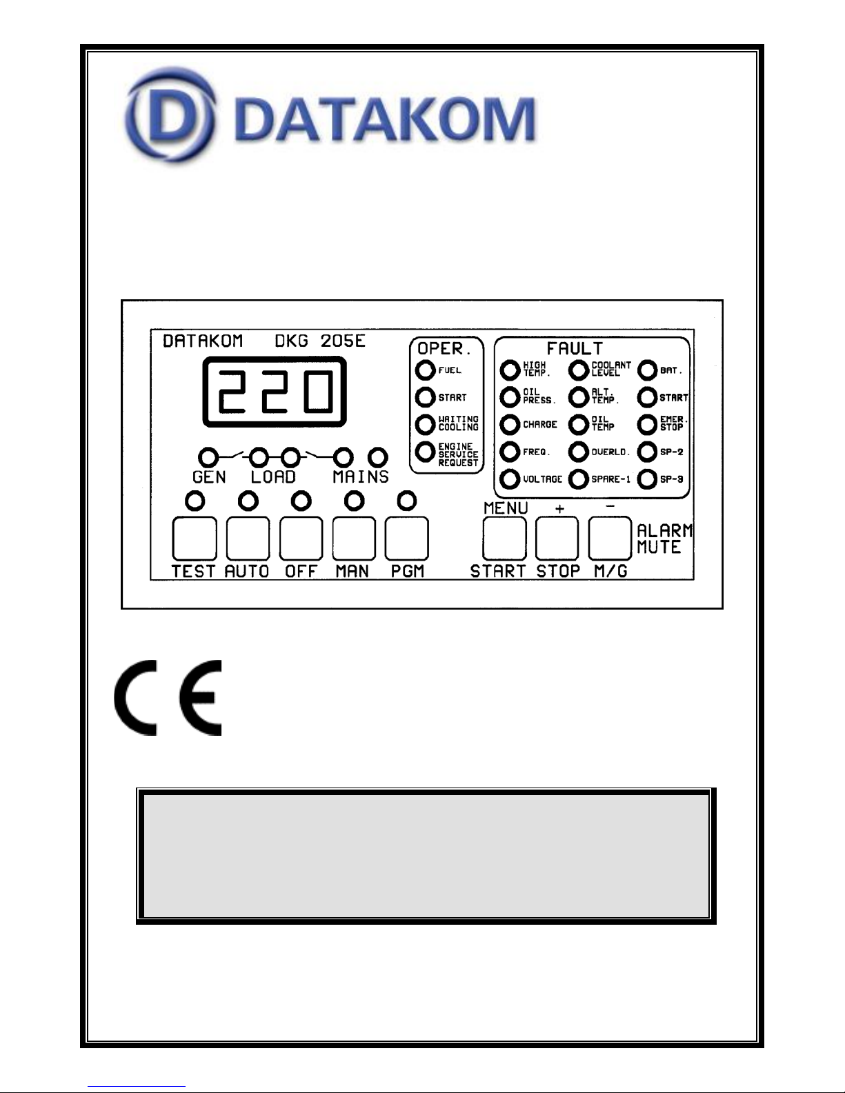
DKG-205 AUTOMATIC
MAINS FAILURE UNIT

TABLE OF CONTENTS
Section
1. PROGRAMMING SUMMARY
2. INSTALLATION
2.1. Introduction to the Control Panel
2.2. Mounting the Unit
2.3. Wiring the Unit
2.4. Inputs and Outputs
2.5. Digital display
2.6. Led displays
2.7. Periodic maintenance request display
2.8. Alarms
2.9. Modes of Operation
3. MAINTENANCE
4. TROUBLESHOOTING
5. PROGRAMMING
6. CALIBRATION
7. TECHNICAL SPECIFICATIONS
8. DECLARATION OF CONFORMITY
9. CONNECTION DIAGRAM
- 3 -
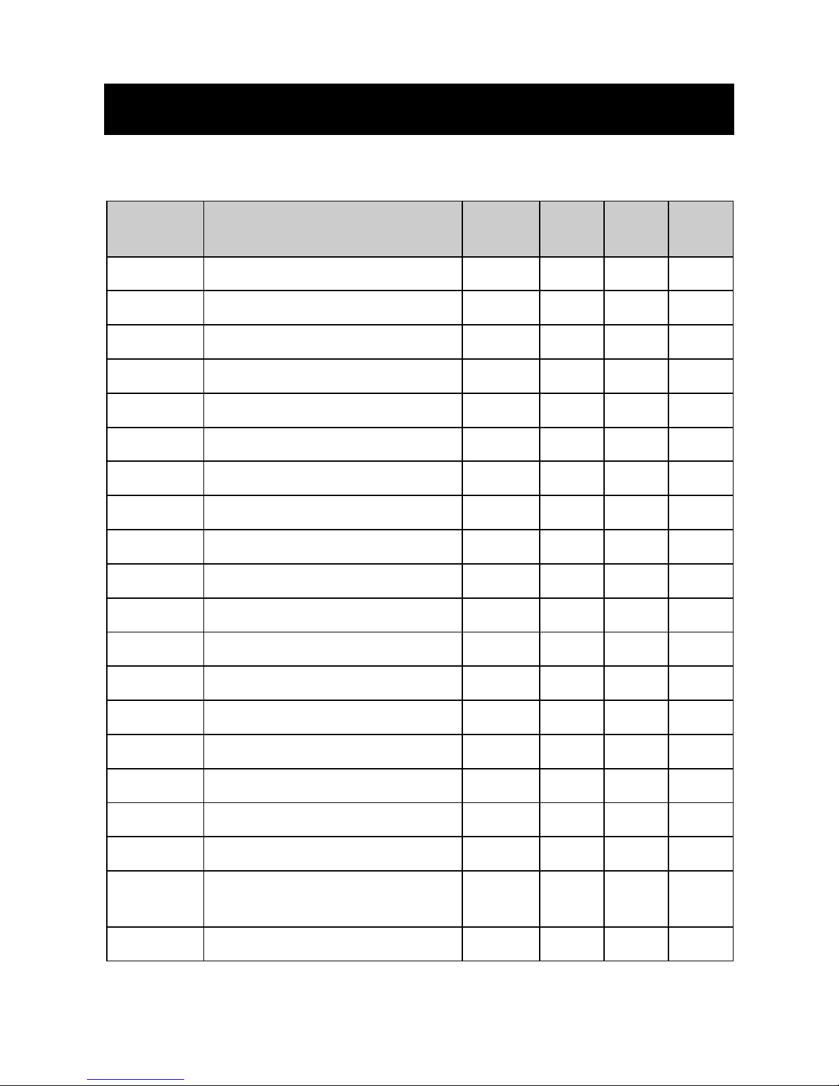
1. PROGRAMMING SUMMARY
To enter the program mode, press the PGM button. The display shows (Pr)
when program mode is selected.
PGM
NUMBER
PROGRAM OPTION
UNIT
FACT
SET
MIN.
VAL.
MAX.
VAL.
P01
Mains Voltage Lower Limit
Volt
170
30
250
P02
Mains Voltage Upper Limit
Volt
270
100
400
P03
Generator Voltage Lower Limit
Volt
180
30
250
P04
Generator Voltage Upper Limit
Volt
270
100
400
P05
Frequency Lower Limit
Hz.
45
10
60
P06
Frequency Upper Limit
Hz.
57
50
100
P07
Frequency Delay Timer
Sec.
3 0 15
P08
DC Supply Upper Limit
Volts
33.0
12.0
33.0
P09
Number of Start Attempts
- 3 1 6 P10
Wait before Start Timer
Sec.
3 0 240
P11
Wait between Starts Timer
Sec.
10 1 30
P12
Start Timer
Sec.
10 2 15
P13
Stop Timer
Sec.
0 0 60
P14
Mains Waiting Timer
Min.
0.5
0
15
P15
Cooling Timer
Min.
1.0
0
15
P16
Mains Contactor Timer
Sec.
1 0 15
P17
Generator Contactor Timer
Sec.
4 0 15
P18
Relay Configuration
- 0 0
7
P19
Maintenance Period (engine
hours)
hours
0 0 750
P20
Maintenance Period (duration)
months
0 0 15

- 4 -
2. INSTALLATION
2.1 Introduction to the Control Panel
The control panel is designed to provide user friendliness for both the installer
and the user. Programming is usually unnecessary, as the factory settings
have been carefully selected to fit most applications. However programmable
parameters allow the complete control over the generating set. Programmed
parameters are stored in a Non Volatile Memory and thus all information is
retained even in the event of complete loss of power.
2.2 Mounting the Unit
The unit is designed for panel mounting. The user should not be able to
access parts of the unit other than the front panel.
Mount the unit on a flat, vertical surface. The unit fits into a standard panel
meter opening of 140x68 millimeters. Before mounting, remove the steel
spring from the unit, and then pass the unit through the mounting opening.
The unit will be maintained in its position by the steel spring.
2.3 Wiring the Unit
WARNING: THE UNIT IS NOT FUSED.
Use external fuses for
Mains phases: R-S-T
Generator phase: L1-L2-L3
Battery positive: BAT(+).
Install the fuses as nearly as possible to
the unit in a place easily accessible for the user.
The fuse rating should be 6 Amps.
WARNING: ELECTRICITY CAN KILL
ALWAYS disconnect the power BEFORE
connecting the unit.

- 5 -
1) ALWAYS remove the plug connectors when inserting
wires with a screwdriver.
2) ALWAYS refer to the National Wiring Regulations
when conducting installation.
3) An appropriate and readily accessible set of
disconnection devices (e.g. automatic fuses) MUST be
provided as part of the installation.
4) The disconnection device must NOT be fitted in a
flexible cord.
5) The building mains supply MUST incorporate
appropriate short-circuit backup protection (e.g. a fuse
or circuit breaker) of High Breaking Capacity (HBC, at
least 1500A).
6) Use cables of adequate current carrying capacity (at
least 0.75mm2) and temperature range.
2.4 Inputs and Outputs
SERIAL DATA CONNECTION: This connection is used to transfer data to the
PC via the serial adapter.
1- GENERATOR CONTACTOR: This output provides energy to the generator
contactor. If the generator phase voltage is outside of the programmed limits,
the generator contactor will be de-energized. In order to provide extra security,
normally closed contact of the mains contactor should be serially connected to
this output. Relay contact rating is 16A/250V-AC
2/3/4- L1/L2/L3: Connect the generator phases to these inputs. The generator
phase voltage upper and lower limits are programmable.
5- GENERATOR NEUTRAL: Neutral terminal for the generator phases.
6- MAINS NEUTRAL: Neutral terminal for the mains phases.
7/8/9- T-S-R: Connect the mains phases to these inputs. The mains voltages
upper and lower limits are programmable.
10- MAINS CONTACTOR: This output provides energy to the mains
contactor. If the voltage of at least one of the mains voltages is outside of the
programmed limits, the mains contactor will be de-energized. In order to
provide extra security, normally closed contact of the generator contactor
should be serially connected to this output. Relay contact rating is 16A/250VAC
11- AUXILIARY RELAY OUTPUT: This relay fulfills 4 different functions
following programming. Relay contact rating is 10A/28V-DC.
1) ALARM RELAY: If an alarm occurs, the relay will be activated. It will be
deactivated when the ALARM MUTE key is pressed.

- 6 -
2) STOP RELAY: The relay will operate during programmed period in order to
stop the engine (Activate to Stop)
3) PREHEAT RELAY: The relay will operate the programmed delay before the
cranking of the engine. It will be deactivated during cranking and reactivated
during the rest period between cranks. It will be deactivated when the engine
runs.
4) CHOKE RELAY: The relay will operate the programmed delay before the
cranking of the engine. It will be deactivated when the engine runs.
12- CRANK OUTPUT: Engine crank output. Relay automatically turns off
when the alternator voltage reaches 100 volts or the alternator frequency
reaches 10Hz.
Relay contact rating is 10A/28V-DC.
13- FUEL OUTPUT: This output is used on engines equipped with a fuel
solenoid. The unit activates this output before starting the engine and
deactivates it to stop it. By programming, this relay can also control 'Activate
to Stop’ type of engines.
Relay contact rating is 10A/28V-DC.
14- CHARGE INPUT: Connect the charging alternator’s lamp output to this
terminal. If the charging alternator fails when the engine is running, the related
alarm indicator will turn on and the alarm output will be activated. This alarm
will not prevent the normal operation of the generating set.
15/16- BAT(+) / BAT(-): The positive (+) and negative (-) terminals of the DC
Supply shall be connected to these terminals. Be careful for the polarization, in
case of polarity error the unit will not operate. The unit operates on both 12V
and 24V battery systems.
17- PROGRAM LOCK INPUT: This input is used to prevent unwanted
modification to programmed values. If this input is left open, program values
can be modified via the front panel buttons, but if this input is connected to DC
Supply (-) it will not possible to change the program values.
18- LOW COOLANT LEVEL SWITCH: Connect the cooling radiator liquid
level switch to this input. This switch shall be negative closing in case of low
liquid level. This input has delayed sampling feature to prevent false detection.
19- SPARE-3 ALARM INPUT: Connect the spare alarm switch to this input.
The switch shall be negative closing type.
20- SPARE-2 ALARM INPUT: Connect the spare alarm switch to this input.
The switch shall be negative closing type.
21- SPARE-1 ALARM INPUT: Connect the spare alarm switch to this input.
The switch shall be negative closing type.
22- HIGH TEMPERATURE SWITCH: Connect the high temperature switch to
this input. This switch shall be negative closing switch type.
23- LOW OIL PRESSURE SWITCH: Connect the low oil pressure switch to
this input. The switch should be negative closing in case of loss of oil
 Loading...