

Page 1

DK-45 User Manual V1.0 (22.09.2016)
DK-45
COMPRESSOR
CONTROLLER
The DK-45 is a high-tech product providing control and
protection of screw or piston type air compressors
driven by electric motors.
The controller incorporates all functions needed in a
compressor control panel. Thus no additional modules
are necessary resulting in lower panel cost.
The “early start” function analyzes the air consumption
trend and runs the compressor so that the pressure
never falls below the low limit.
The controller is directly supplied from the 230/400V
utility network. It provides fail contact and sensor
supplies internally, removing the need for a supply
transformer in the panel.
Utility mains voltages and frequency can be read on
the controller. It offers low/high voltage and phase
order protections.
The 2.9” wide, 128x64 pixels graphical screen displays
values in bigger size and with graphic support.
The logic level Modbus RTU communication port of the
controller allows computer connection providing
monitoring and program parameter adjusting.
Optically isolated digital inputs feature noise filtering
allowing fault-free operation in electrically noisy
environments.
The controller provides 5 relay outputs rated at 5
Amps.
The controller configuration may be done through the
front panel or using the free PC software. The PC
software is available for free download at
manufacturer’s website.
It is possible to monitor and record the controller using
the free RAINBOW+ software.
● Graphical LCD screen: 128x64 pixels, 2.9”
● Automatic operation from output pressure
● Voltage protection relay function
● Phase order protection relay function
● Analog speed control output
● Multiple compressor support
● Flexible motor hours calculation algorithm
● Early start function preventing pressure drop
● Dryer control function
● History records
● 5 independent service counters
● Supports various topologies
● Displays utility mains voltages
● No external transformer needed
● Star / Delta start-up
● Load solenoid control
● 5 programmable relay outputs
● Optically isolated, programmable digital inputs
● 2 pressure sensor inputs
● 2 temperature sensor inputs
● Adjustable sensor characteristics
● Logic level serial port
● MODBUS-RTU communications
● Password protected front panel programming
● Low panel depth, easy installation
● Wide operating temperature range
● Sealed front panel (IP65 with gasket)
DESCRIPTION
FEATURES
Page 2

DK-45 Kullanım Kılavuzu V1.0 (22.09.2016)
- 2 -
Any unauthorized use or copying of the contents or any part of this document is prohibited.
This applies in particular to trademarks, model denominations, part numbers and drawings.
This document describes minimum requirements and necessary steps for the successful installation of
the DK-45 family controllers.
Follow carefully advices given in the document. These are often good practices for the installation of
compressor controllers which reduce future issues.
For all technical queries please contact Datakom at below e-mail address:
If additional information to this manual is required, please contact the manufacturer directly at below email address:
Please provide following information in order to get answers to any question:
- Device model name (see the back panel of the controller),
- Complete serial number (see the back panel of the controller),
- Firmware version (read from the display screen),
- Measuring-circuit voltage and power supply voltage,
- Precise description of the query.
REVISION
DATE
AUTHOR
DESCRIPTION
01
19.06.2015
MH
First edition, firmware version 1.0
CAUTION: Potential risk of injury or death.
WARNING: Potential risk of malfunction or material damage.
ATTENTION: Useful hints for the understanding of device operation.
REVISION HISTORY
TERMINOLOGY
QUERRIES
ABOUT THIS DOCUMENT
COPYRIGHT NOTICE
Page 3

DK-45 Kullanım Kılavuzu V1.0 (22.09.2016)
- 3 -
Electrical equipment should be installed only by qualified
specialist. No responsibility is assured by the manufacturer or
any of its subsidiaries for any consequences resulting from the
non-compliance to these instructions.
Check the controller for cracks and damages due to
transportation. Do not install damaged equipment.
Do not open the controller. There are no serviceable parts inside.
Fuses must be connected to the power supply and phase voltage
inputs, in close proximity of the controller.
Fuses must be of fast type (FF) with a maximum rating of 6A.
Disconnect all power before working on equipment.
When the controller is connected to the network do not touch
terminals.
Short circuit terminals of unused current transformers.
Any electrical parameter applied to the device must be in the
range specified in the user manual. Although the controller is
designed with a wide safety margin, over-range parameters may
reduce lifetime, alter operational precision or even damage the
controller.
Do not try to clean the device with solvent or the like. Only clean
with a dump cloth.
Verify correct terminal connections before applying power.
Only for front panel mounting.
SAFETY NOTICE
Failure to follow below instructions
will result in death or serious injury
Page 4

DK-45 Kullanım Kılavuzu V1.0 (22.09.2016)
- 4 -
1. INSTALLATION INSTRUCTIONS
1.1. FRONT AND REAR PANELS
1.2. MECHANICAL INSTALLATION
1.3. ELECTRICAL INSTALLATION
1.4. CONNECTION DIAGRAM
2. PUSHBUTTON FUNCTIONS
3. SCREEN SCROLLING
4. MODES OF OPERATION
5. ALARMS AND WARNINGS
5.1. SERVICE ALARM OPTIONS
5.2. LIST OF FAULT CODES
6. OTHER FEATURES
6.1. RESETTING SERVICE COUNTERS
6.2. MODIFYING MOTOR RUN HOURS
6.3. SELECTION OF MOTOR HOURS COUNTING METHOD
6.4. CONNECTION TOPOLOGIES
6.5. PREVENTING PRESSURE LOSS
6.6. ALARM HISTORY
6.7. DRYER FUNCTION
6.8. VARIABLE UNLOAD TIMER
6.9. PID CONTROL AND ANALOG OUTPUT (PWM)
6.10. MOTOR PTC INPUT
7. MULTI-COMPRESSOR OPERATION
8. DIGITAL INPUTS
9. RELAY OUTPUTS
10. PROGRAMMING
10.1. ENTERING THE PROGRAMMING MODE
10.2. LIST OF PARAMETERS
11. MODBUS COMMUNICATIONS
11.1. DESCRIPTION
11.2. MODBUS REGISTER LIST
11.3. ALARMS, WARNINGS, SERVICE REQUESTS
12. DECLARATION OF CONFORMITY
13. TECHNICAL SPECIFICATIONS
TABLE OF CONTENTS
Page 5

DK-45 Kullanım Kılavuzu V1.0 (22.09.2016)
- 5 -
Before installation:
Read the user manual carefully, determine the correct connection diagram.
Remove all connectors and mounting brackets from the controller, then pass the controller
through the mounting opening.
Put mounting brackets and tighten. Do not tighten too much, this can brake the enclosure.
Make electrical connections with plugs removed from sockets, then place plugs to their sockets.
Take into consideration that supply inputs are isolated from measurement inputs.
Be sure that adequate cooling is provided.
Be sure that the temperature of the environment will not exceed the maximum operating
temperature in any case.
Below conditions may damage the device:
Incorrect connections.
Incorrect power supply voltage.
Voltage at measuring terminals beyond specified range.
Overload or short circuit at relay outputs
Connecting or removing data terminals when the controller is powered-up.
High voltage applied to communication ports.
Ground potential differences at non-isolated communication ports.
Excessive vibration, direct installation on vibrating parts.
Below conditions may cause abnormal operation:
Power supply voltage below minimum acceptable level.
Power supply frequency out of specified limits
1.1 INSTALLATION INSTRUCTIONS
Page 6

DK-45 Kullanım Kılavuzu V1.0 (22.09.2016)
- 6 -
WALL
40mmmin 60mm
Panel Cutout Dimensions Required Panel Depth
1.1. FRONT AND REAR PANELS
1.2. MECHANICAL INSTALLATION
Page 7

DK-45 Kullanım Kılavuzu V1.0 (22.09.2016)
- 7 -
Although the controller is protected against electromagnetic disturbance, excessive
disturbance can affect the operation, measurement precision and data communication
quality.
ALWAYS remove plug connectors when inserting wires with a screwdriver.
Fuses must be connected to the power supply and phase voltage inputs, in
close proximity of the controller.
Fuses must be of fast type (FF) with a maximum rating of 6A.
Use cables of appropriate temperature range.
Use adequate cable section, at least 0.75mm2 (AWG18).
Follow national rules for electrical installation.
Connect only the provided serial port adapter to the serial communication
port.
Do not install the controller close to high
electromagnetic noise emitting devices like
contactors, high current busbars, switchmode power
supplies and the like.
1.3. ELECTRICAL INSTALLATION
Page 8

DK-45 Kullanım Kılavuzu V1.0 (22.09.2016)
- 8 -
1.4. CONNECTION DIAGRAM
Page 9

DK-45 Kullanım Kılavuzu V1.0 (22.09.2016)
- 9 -
Three pushbuttons on the front panel allow access to programming and measuring screens.
BUTTON
DESCRIPTION
FUNCTION
MENU
Displays the next parameter.
Reset alarms.
PROGRAMMING: Save the adjusted parameter.
RUN
Reset alarms and run the compressor.
PROGRAMMING: Increase parameter value.
STOP
Reset alarms and stop the compressor.
PROGRAMMING: Decrease parameter value.
2. PUSHBUTTON FUNCTIONS
Page 10

DK-45 Kullanım Kılavuzu V1.0 (22.09.2016)
- 10 -
When the controller powers-on, the top part of the display will show (P1) the first pressure sensor (or first
pressure switch). The pressure unit may be displayed as PSI or Bar following program parameter setting.
The upper visual bar fills up in relation with the current pressure level.
The right end of the bar is always set to the maximum displayable pressure, which is E.03 High Pressure
Alarm Limit.
The left end of the bar is set to the minimum displayable pressure level.
The (start) icon on the bar indicates the E05. Starting Pressure, the (stop) icon indicates the E04.
Stop Pressure and the icon indicates the E.03 High Pressure Alarm Limit.
The bottom part of the display shows (T1) the first temperature sensor. The temperature unit may be °C
(degrees celcius) or °F (degrees Fahrenheit) following program parameter setting.
The lower visual bar fills up in relation with the current temperature.
The right end of the bar is always set to the maximum displayable pressure, which is E.08 High
Temperature Alarm Limit. The left end of the bar is set to the minimum displayable temperature.
The icon indicates the E.08 High Temperature Alarm Limit.
If a relay output is set as the Fan Relay (see chapter 9), when this relay is active a fan icon will appear at
the bottom right corner of the display screen.
Through parameter setting in the programming menu, (P2) second pressure value or the differential
pressure P2-P1 (DP), (T2) second temperature sensor or the differential temperature T1-T2 (DT) may be
displayed in a second pressure/temperature screen.
All measurement screens are scrolled by depressing the MENU pushbutton.
First Pressure/Temperature Screen
Second Pressure/Temperature Screen
3. SCREEN SCROLLING
Page 11

DK-45 Kullanım Kılavuzu V1.0 (22.09.2016)
- 11 -
Phase-to-Neutral voltage screen
Phase-to-Phase voltage screen
Run Hours Screen
Service Timers Screen
This screen shows remaining time to services A,B, C, D and E in hours. Service timers operate on a
decremental basis. Service bars are emptied with relation to timer values.
Page 12

DK-45 Kullanım Kılavuzu V1.0 (22.09.2016)
- 12 -
Information Screen
If the E.47 Motor Control PWM Signal is enabled, then instead of start/stop pressures, this screen will
show the E.48 Motor Control PWM Set Pressure (DRVR SET PRS) parameter.
Alarm history Screen
Alarm history will be described in detail in chapter 6.6.
Above screens or values shown in screens may not be displayed depending on program parameter
setup.
Display of some values are selected with program parameters.
Display screens may differ following compressor
manufacturers.
When an alarm occurs, the display will show the alarm code
and alarm symbol.
Page 13

DK-45 Kullanım Kılavuzu V1.0 (22.09.2016)
- 13 -
Below is the description of some abbreviations displayed on the screen:
ABBREVIATION
DESCRIPTION
P1
First pressure sensor value or first pressure switch position
P2
Second pressure sensor value or second pressure switch position
DP
P2-P1 differential pressure (Delta pressure)
T1
First temperature sensor value
T2
Second temperature sensor value
DT
T1-T2 differential temperature (Delta temperature)
L-1
Voltage between phase L1 and neutral
L-2
Voltage between phase L2 and neutral
L-3
Voltage between phase L3 and neutral
L12
Voltage between phases L1 and L2
L23
Voltage between phases L2 and L3
L31
Voltage between phases L3 and L1
FRQ
Frequency
RUN H.
Total motor run hours (On-load + off-load)
LOAD H.
On-load motor run hours
LD/RUN
(On-load) / (Total) motor hours ratio
STRTS/h
Maximum number of starts per hour
DRVR SET PRS
Motor control PWM signal set pressure
STRT PRES
Compressor’s starting pressure
STOP PRES
Compressor’s stop pressure
MASTR DEV. ADR
Master device address (multi-compressor operation)
NUM OF DEVICES
Number of devices (multi-compressor operation)
SOFTWARE VER.
Device firmware version
msec
milisecond
sec
second)
min
minute
h (hour)
hour
V
Volt
Hz
Hertz
%
percent
Page 14

DK-45 Kullanım Kılavuzu V1.0 (22.09.2016)
- 14 -
Below is the description of some icons displayed on the screen:
ICON
DESCRIPTION
OFF, disabled, not-OK
Remote Start
Reset, cancel, disable
Enabled, adjusted, action complete, OK
Enter / change password
Motor PTC
Pressure-2 in Separator filter
Waiting the pressure in separator filter to drop
Remote Start / Stop
Waiting input signal
Max Slaves
Auto restart register, PORO
Dryer function
Insufficient pressure (run the compressor)
Sufficient pressure (stop the compressor)
Remaining hours to service
Run hour counters
Programming
Remote Stop
Page 15

DK-45 Kullanım Kılavuzu V1.0 (22.09.2016)
- 15 -
Selecting the mode of operation:
When powered-up, the device turns-on all lights during 3 seconds for verification. Then it goes into STOP
mode and the STOP led turns on.
The compressor may be run with the REMOTE START signal ( icon displayed during 5 seconds) or
by depressing the RUN pushbutton.
If the E.27 Safety Timer is not expired, then the RUN led will flash until the expiration of the timer. Then
the motor will run is the output pressure is below E.05 Start Pressure.
The compressor is usually stopped with REMOTE STOP signal ( icon is displayed during 5 seconds)
or by depressing the STOP pushbutton.
Stop procedure:
STOP led starts flashing.
If the compressor is under load, the load relay will release and the motor continues to run during E.27
Safety Delay Timer or E.25 Unload Timer (whichever is longer). During this period the RUN mode may
be resumed by depressing the RUN pushbutton.
If the STOP pushbutton is depressed again during off-load running, then the compressor will stop
immediately.
The STOP led will continue to flash until the complete stop.
4. MODES OF OPERATION
If an alarm occurs the compressor will stop immediately and
the screen will display the alarm code and related icon.
Please see chapter_5 for the complete list of alarm codes.
If the compressor is running off-load and the STOP pushbutton
is depressed, it will continue to run until the expiration of the
E.25 Unload Timer.
By depressing again the STOP pushbutton the compressor may
be stopped immediately.
Page 16

DK-45 Kullanım Kılavuzu V1.0 (22.09.2016)
- 16 -
Start-up procedure:
If utility mains voltages and frequency is between set limits and the phase order is correct, the the LINE
led will turn on. The compressor can run only when the LINE led is on. Otherwise it cannot be run by any
means.
The RUN mode is selected by depressing the RUN pushbutton or by setting the REMOTE START
signal (if enabled). At this stage the compressor will run only when the output pressure falls below the
E.05 Start Pressure (or when the pressure switch closes).
Before the compressor runs, the STAR relay will be activated. After the expiration of E.15 Delay
Between Relays Timer the MAIN relay will be active. Thus the motor will start-up in STAR configuration.
After the expiration of E.22 Star Timer the STAR relay will release. After the expiration of E.23 Star Delta
Timer the DELTA relay will be active.
After the expiration of E.24 Time Before Load, the LOAD relay will become active and the compressor
starts producing compressed air.
Unloading and reloading of the compressor:
When the output pressure reaches E.04 Stop Pressure limit (or the pressure switch opens) the load
relay will release and the motor will run off-load during E.25 Unload Timer. If the pressure falls below the
E.05 Start Pressure before expiration of the timer, then the LOAD relay will be activated again.
Stopping and restarting following output pressure:
If the output pressure stays over the E.05 Start Pressure during E.25 Unload Timer, then the DELTA
relay relases. After E.15 Delay Between Relays the MAIN relay releases and the compressor stops.
In this position the RUN led is flashing.
The maximum number of start cycles that the compressor is allowed to perform in 1 hour is defined by the
F.01 Max Starts per Hour program parameter.
If the maximum number of starts is reached, then following stop cycles will be skipped until the expiration
of 1 hour period.
Page 17

DK-45 Kullanım Kılavuzu V1.0 (22.09.2016)
- 17 -
Abnormal conditions of a compressor are divided into 3 categories, being WARNINGS, ALARMS and
SERVICE REQUESTS.
Warnings are the lowest priority fault conditions and result only in visual warnings.
Alarms are highest level fault conditions and cause the compressor to stop immediately, the alarm relay
to operate (if enabled) and the controller give visual warning.
When a fault condition occurs, the related fault code and icon will appear on the screen. If the fault
condition is an alarm, then the ALARM led will turn on. If the fault is a service request then the SERVICE
led turns on.
Warnings may be cancelled by depressing the MENU pushbutton. Alarms cannot be cancelled with
pushbuttons. The alarm signal must also be removed. However the depression of the MENU
pushbutton will cause the large alarm icon to disappear and the alarm goes to the upper right corner of
the screen.
5. ALARMS AND WARNINGS
When the MENU pushbutton is depressed, the display will
rever to the “measurements” screen.
Page 18

DK-45 Kullanım Kılavuzu V1.0 (22.09.2016)
- 18 -
Following the selection of the program parameter F.02 Stop Service Request, the expiration of a service
timer may simply cause a visual warning and the activation of the alarm relay, or it may also cause below
behaviour:
TIME TO SERVICE
ACTION TAKEN
> 100 hours
No warning occurs
100 hours
Service request warning is given and the service led turns on. The
compressor continues normal operation.
0 hours
The compressor stops. Service request warning is given and the service led
turns on. The compressor may be run again by depressing the RUN
pushbutton.
-100 hours
The compressor stops. Service request warning is given and the service led
turns on. The compressor may be run again by depressing the RUN
pushbutton.
Between -120 and -200 hours,
every 20 hours
The compressor stops. Service request warning is given and the service led
turns on. The compressor may be run again by depressing the RUN
pushbutton.
Between -210 and -300 hours
and every 10 hours
The compressor stops. Service request warning is given and the service led
turns on. The compressor may be run again by depressing the RUN
pushbutton.
-300 hours
The compressor stops. Service request warning is given and the service led
turns on. The compressor will run only after service is performed.
5.1. SERVICE ALARM OPTIONS
Page 19

DK-45 Kullanım Kılavuzu V1.0 (22.09.2016)
- 19 -
ICON
CODE
DESCRIPTION
FAULT LEVEL
ALARM 01
01
Pressure Safety Switch Open
ALARM
ALARM 02
02
High Pressure
ALARM
ALARM 03
03
Pressure sensor failure
ALARM
ALARM 04
04
High temperature Alarm
ALARM
ALARM 05
05
High Temperature Warning
WARNING
ALARM 06
06
Temperature sensor failure
ALARM
ALARM 07
07
Low temperature Alarm
ALARM
ALARM 08
08
Fan motor high temperature
ALARM
ALARM 09
09
Motor PTC high temperature
ALARM
ALARM 10
10
Voltage unbalance
ALARM
ALARM 11
11
High voltage
ALARM
ALARM 12
12
Low voltage
ALARM
ALARM 13
13
High frequency
ALARM
ALARM 14
14
Low frequency
ALARM
5.2. LIST OF FAULT CODES
Page 20

DK-45 Kullanım Kılavuzu V1.0 (22.09.2016)
- 20 -
ICON
CODE
DESCRIPTION
FAULT LEVEL
ALARM 15
15
Phase order failure
ALARM
ALARM 16
16
Air filter clogged
WARNING
ALARM 17
17
Max starts per hour exceeded
WARNING
ALARM 18
18
Emergency stop
ALARM
ALARM 19
19
Internal failure
WARNING
ALARM 20
20
High differential pressure
ALARM
ALARM 21
21
Sensor-2 high pressure
ALARM
ALARM 22
22
Pressure sensor-2 failure
ALARM
ALARM 23
23
Sensor-2 high temperature
/ Delta_T (tS2-tS1) Alarm
ALARM
ALARM 24
24
Temperature sensor-2 failure
ALARM
ALARM 25
25
Sensor-2 low temperature alarm
ALARM
ALARM 26
26
Air in separator filter
WARNING
ALARM 27
27
Delta temperature sensor-2
WARNING
ALARM 28
28
Motor thermic protection switch open (Motor
Overload)
ALARM
ALARM 29
29
Sensor-2 low pressure
ALARM
Page 21
DK-45 Kullanım Kılavuzu V1.0 (22.09.2016)
- 21 -
ICON
CODE
DESCRIPTION
FAULT LEVEL
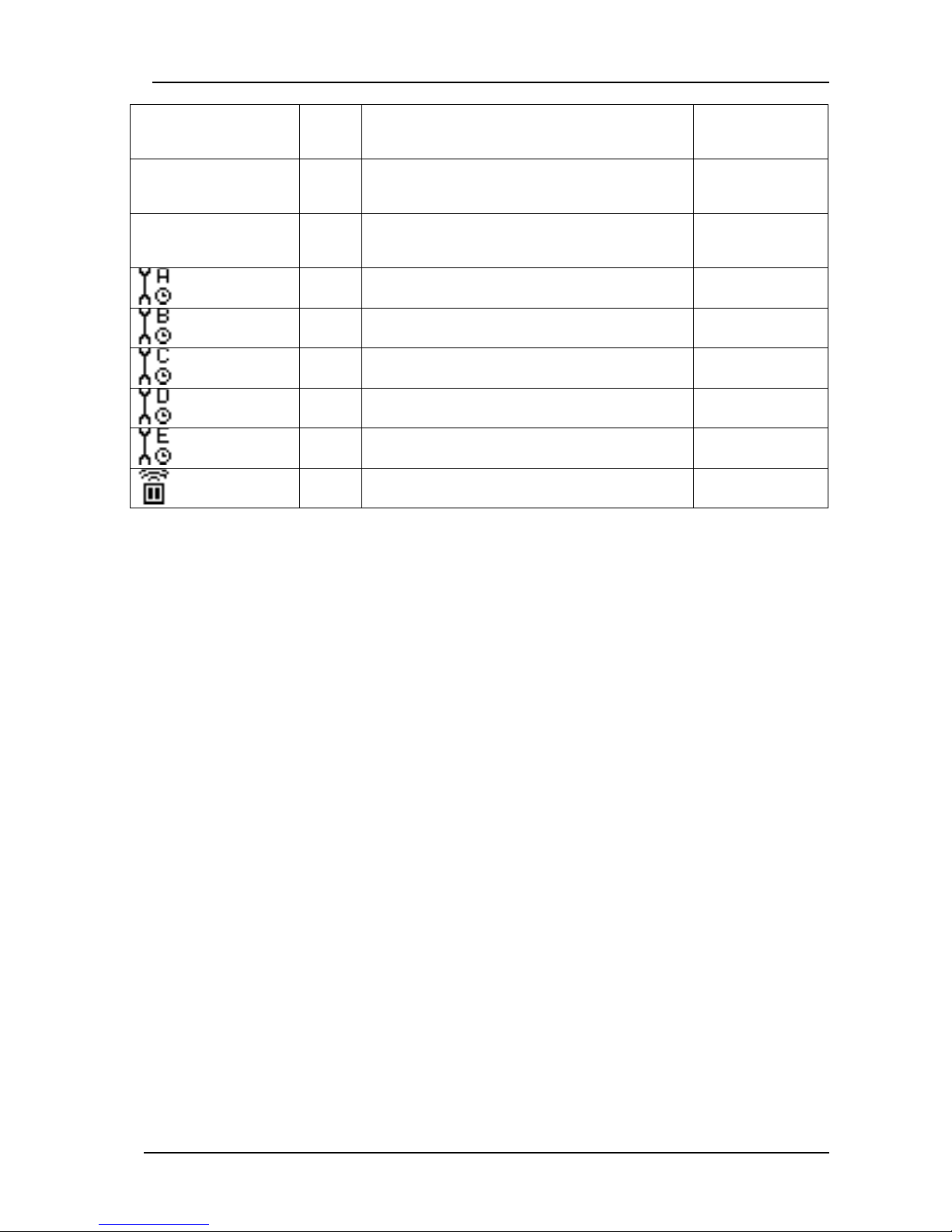
ALARM 30
30
Input expected
WARNING
ALARM 50
50
Data line failure (multiple control)
WARNING
SERVİS A
100
Service period A exceeded
SERVICE
SERVİS B
101
Service period B exceeded
SERVICE
SERVİS C
102
Service period C exceeded
SERVICE
SERVİS D
103
Service period D exceeded
SERVICE
SERVİS E
104
Service period E exceeded
SERVICE
Uzak Durdur
200
Remote stop signal
-
Page 22
DK-45 Kullanım Kılavuzu V1.0 (22.09.2016)
- 22 -
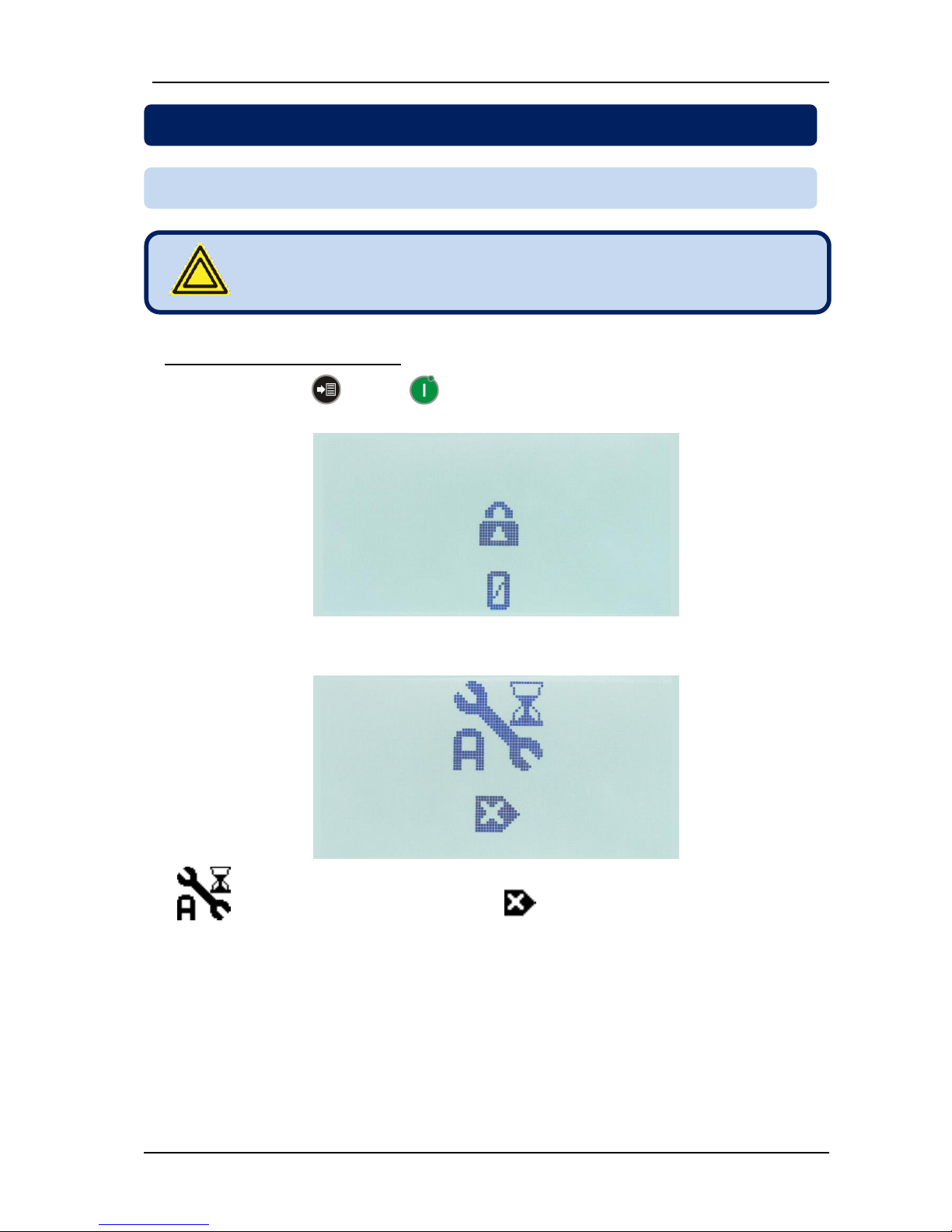
In order to reset service counters:
- Hold pressed MENU and RUN pushbuttons during 3 seconds. If the HIGH LEVEL
password is not entered in the last 90 minutes, then the controller will ask for password.
- Enter password.
- (hours remaining to service A) icon and (reset) icon will be displayed.
6. OTHER FEATURES
6.1. RESETTING SERVICE COUNTERS
Service counters can be reset only when the compressor is in
STOP state.
Page 23
DK-45 Kullanım Kılavuzu V1.0 (22.09.2016)
- 23 -
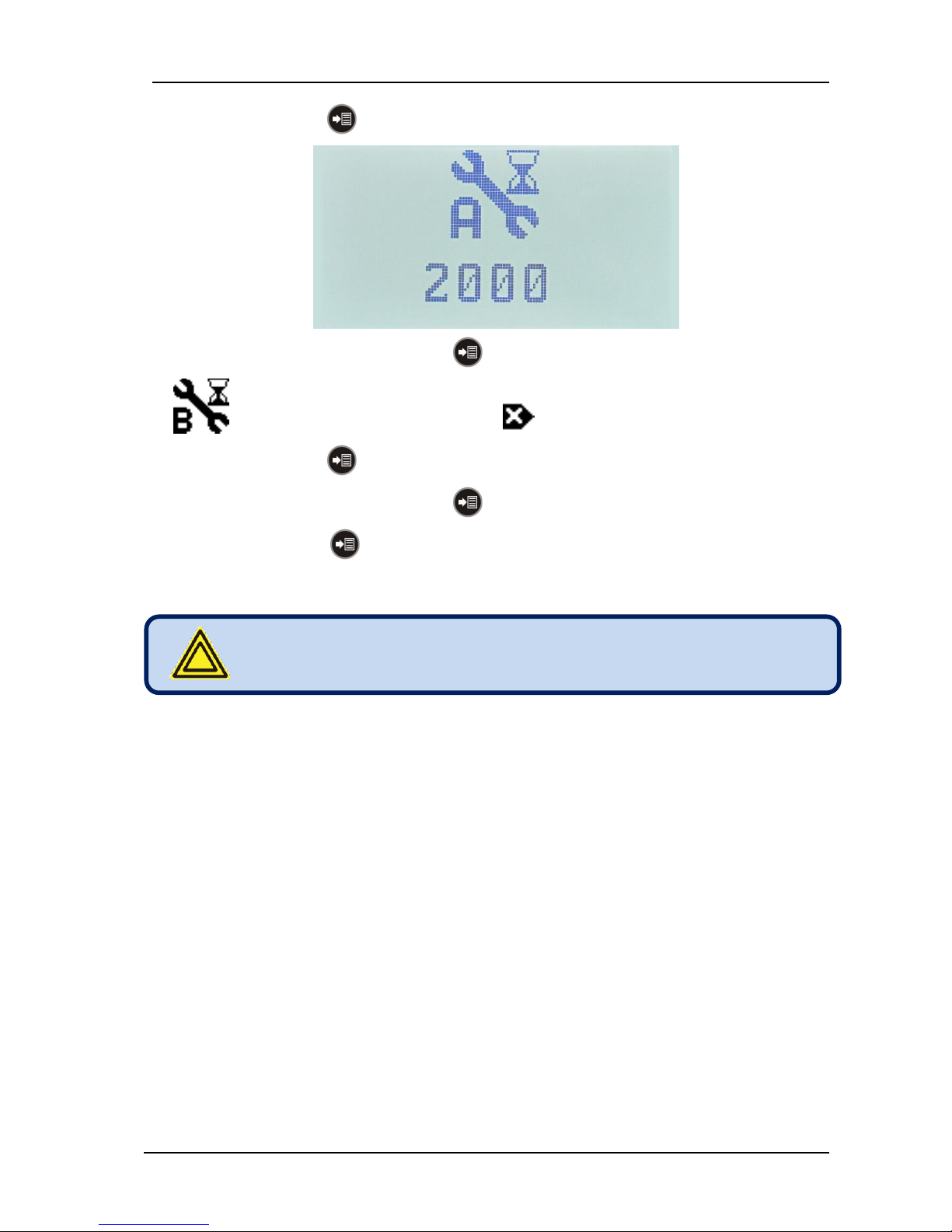
- Press again the MENU pushbutton. The remaining hours to service A will be displayed.
- In order to reset service A, hold the MENU button pressed during 3 seconds.
- (hours remaining to service B) icon and (reset) icon will be displayed.
- Press again the MENU pushbutton. The remaining hours to service B will be displayed.
- In order to reset service B, hold the MENU button pressed during 3 seconds.
- With successive MENU button keypresses other (C,D,E) service counters may be displayed
and reset.
After the last counter, the display will revert to the
measurement screen.
Page 24
DK-45 Kullanım Kılavuzu V1.0 (22.09.2016)
- 24 -
Below are run hour counters of the device.
MESSAGE
DESCRIPTION
RUN H.
Total motor run hours (on_LOAD + off_LOAD)
This counter increments while the motor is running.
LOAD H.
Total on_LOAD run hours (LOAD output active)
This counter increments while the LOAD led is on.
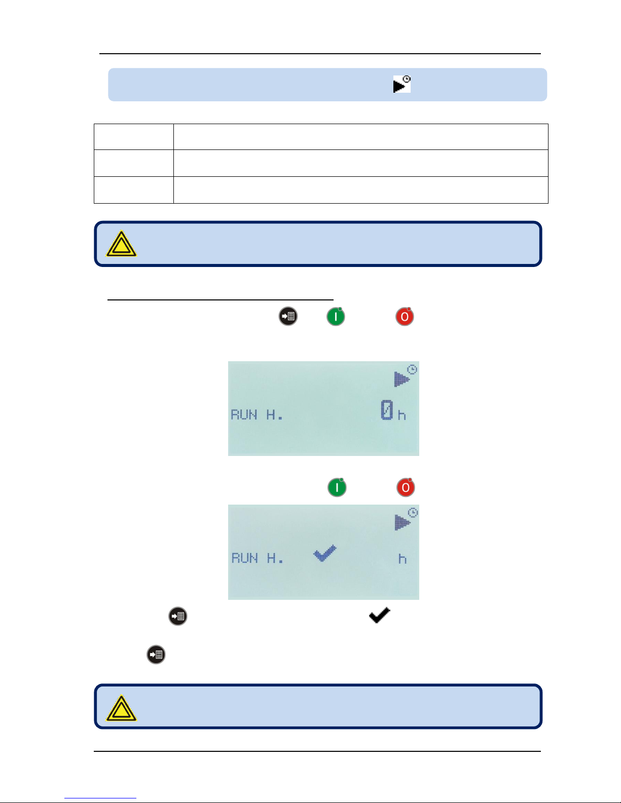
In order to set hour run counters to a given value:
- Hold pressed during 3 seconds MENU , RUN and STOP pushbuttons. If the HIGH
LEVEL password is not entered in the last 90 minutes, then the controller will ask for password.
- Enter password.
- “RUN H.” Message and the zero counter value will be displayed.
- Adjust the counter to the desired value using RUN and STOP pushbuttons.
- If the MENU pushbutton is held pressed for 3 seconds, (adjusted) icon will be displayed
announcing that the counter is set to its new value.
If MENU pushbutton is shortly depressed then the counter value will not change and the next
counter’s value will be displayed. The counter value may be modified and saved as explained above.
6.2. MODIFYING MOTOR RUN HOURS
Hour run counters can be modified only when the compressor is
in STOP state.
After modification, the display will revert to the measurement
screen.
Page 25
DK-45 Kullanım Kılavuzu V1.0 (22.09.2016)
- 25 -
The controller offers the possibility of counting motor hours with a variable coefficient depending on
output air temperature.
The usage of variable coefficient is selected with F.03 Motor Hours Calculation Method parameter. If
this parameter is not activated, then all service and motor hour counters are calculated with a coefficient
of 1.00, independent of the output air temperature.
When the variable coefficient calculation is activated:
On-LOAD operation,
Below 90 °C coefficient is 1.00
Between 90-95 °C coefficient is 1.50
Between 95-100 °C coefficient is 2.00
Above 100 °C coefficient is 3.00
Off_LOAD operation
Below 90 °C coefficient is 0.50
Between 90-95 °C coefficient is 0.75
Between 95-100 °C coefficient is 1.00
Above 100 °C coefficient is 1.50
6.3. SELECTION OF MOTOR HOURS COUNTING METHOD
These coefficients are valid for all service and motor run hour
counters.
Page 26
DK-45 Kullanım Kılavuzu V1.0 (22.09.2016)
- 26 -
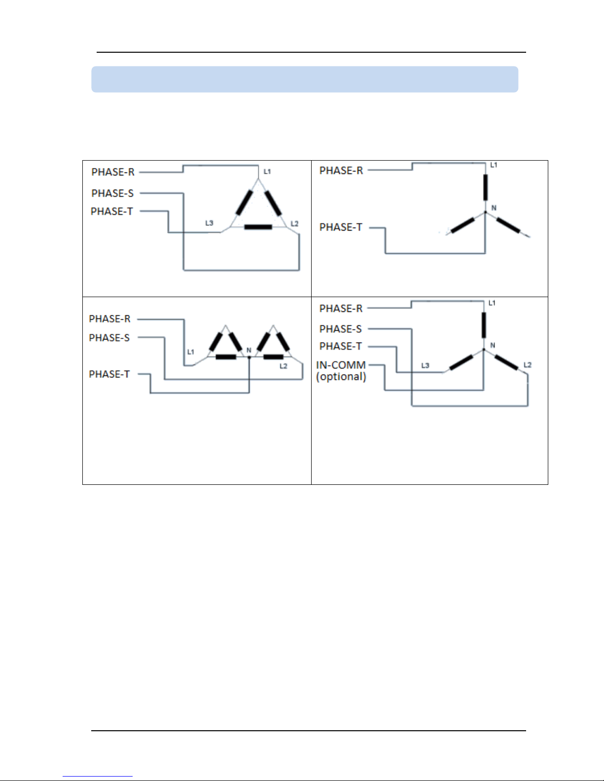
The controller supports various utility mains connection topologies. The selection is made through C.04
Connection Topology parameter.
Connection diagrams for various topologies are below:
C.04 = 3
C.04 = 1
C.04 = 2
C.04 = 3
Supply and measurement inputs of the module are
isolated.
Above connection requires a different product variant
which should be notified in the order.
6.4. CONNECTION TOPOLOGIES
Page 27
DK-45 Kullanım Kılavuzu V1.0 (22.09.2016)
- 27 -
If the outputs pressure stays above E.05 Start Pressure during E.25 Unload Timer, then the controller
will stop the motor. When the motor is at rest, if the pressure falls below E.05 Start Pressure then the
motor will run again.
A delay equal to E.22+E.23+E.24+E.15x3 will pass until the compressor enters under load again.
During this period, depending on air consumption, the pressure may fall well below E.05 Start Pressure.
But in most systems the pressure is not desired to fall below E.05 Start Pressure.
In order to prevent this unwanted situation, the controller offers 3 different solutions and the related
procedure is selected through E.38 Prevent Pressure Loss parameter. Using these procedures, the
controller redetermines dynamically the startup pressure (Pi: Restart Pressure).
E.38 = 0 No special care is taken for pressure loss. Restart pressure is always E.05 parameter.
E.38 = 1 At the moment where the compressor takes the load, if the pressure is below E.05 Start
Pressure, the controller will increase the Restart Pressure by 0.1 bar. If the prssure is above the E.05
Start Pressure, the controller will decrease the Restart Pressure by 0.1 bar. Thus it will try to put the
compressor under under load exactly when the pressure equals to the E.05 Start Pressure.
E.38 = 2 When the compressor unloads after reaching the E.04 Stop Pressure, the controller
monitors the pressure decrease in the first 8 seconds and recalculates the Restart Pressure dynamically
for each restart period.
6.5. PREVENTING PRESSURE LOSS
At the end of E.25 Unload Timer, if the pressure is above E.05
Start Pressure but below Restart Pressure, then the compressor
continues off_load operation.
Page 28
DK-45 Kullanım Kılavuzu V1.0 (22.09.2016)
- 28 -
The controller keeps record of last 9 alarms in its alarm history list.
The alarm history may be visualized on the screen or read through Modbus communication.
Alarm history is kept in a non-volatile memory and is not affected by power failures.
The primary condition for an alarm to be saved to the history, is that the alarm is different from the last
one or the motor has run at least 6 minutes from the last alarm.
In order to display the latest alarm on the list press MENU button until (alarm history) icon is
displayed. The alarm history may also be accessed from the programming menu. Please see chapter 10
for this.
In order to visualize previous alarms please use RUN and STOP buttons.
In order to reset the alarm history, please long-press the STOP button when the motor is at rest.
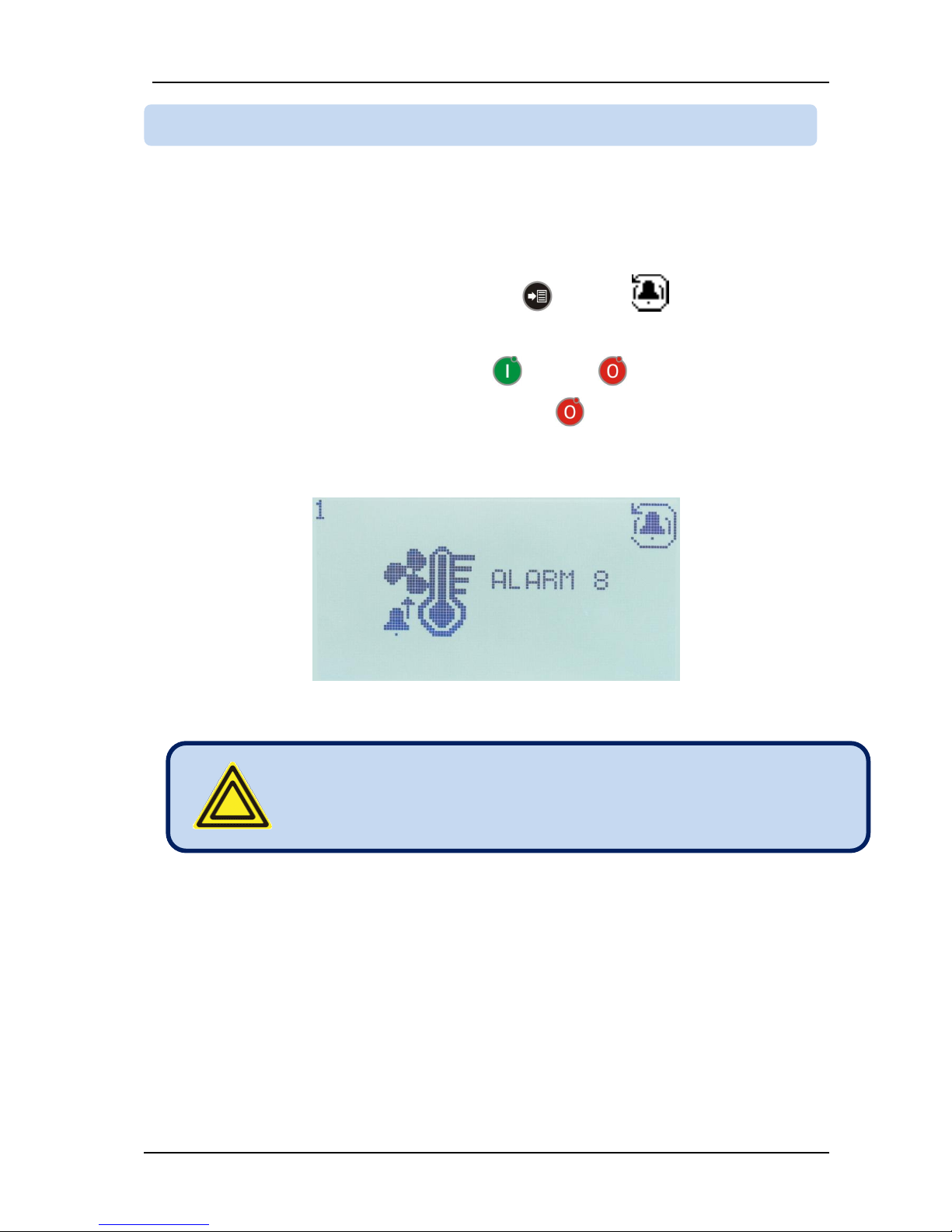
In the alarm history screen, the history record number (1 to 9) appears at top left of the screen. The alarm
history icon appears at the top right. The alarm icon and alarm number appears at the center of the
screen.
6.6. ALARM HISTORY
When the alarm list is displayed the STOP button is always
enabled and stops the compressor. Run button is not active and
does not run the compressor. In order to scan the alarm history
when the motor is running, please use the RUN button.
Page 29
DK-45 Kullanım Kılavuzu V1.0 (22.09.2016)
- 29 -
If E.56 Dryer Delay Timer is adjusted to a value other than zero, the “STARTUP PROCEDURE”
described in chapter 4 will be performed in a different manner.
If the timer is not zero, then the MAIN relay output will be activated before the STAR relay and will stay
active during E.56 Dryer Delay Timer.
Thus the air dryer supplied from the main contactor will be run during the desired period before the
compressor starts producing compressed air.
When the timer is elapsed, the STAR relay output becomes active and the startup predure is performed
as explained in chapter 4.
This feature is designed to prevent the motor running unnecessarily off_load, consuming energy.
When the pressure reaches E.04 Stop Pressure limit (or the pressure switch opens) the LOAD relay will
open. During E.25 Unload Timer or E.27 Safety Delay Timer (whichever longer) the motor continues to
run, then stops.
If E.26 Variable Unload Timer parameter is adjusted to 1 and the period where the motor is at rest is
longer than E.25 Unload Timer then the controller decides that the motor has run unnecessarily longtime
off_LOAD and shortens the Unload Timer for the next cycle by 1 minute, but never below 2 minutes.
If the compressor is stopped with the STOP button or programming mode is selected, then the
Unload Timer is reset to E.25 Unload Timer parameter value.
If E.47 Motor PWM Signal (0-10V) parameter is set to 1 then the PID controlled analog output of the
module is activated. The analog control signal is output from the terminal number 19, 0-10V OUT.
The analog output will control the motor speed in order to match E.48 PWM Set Pressure. The control is
performed by changing the analog output voltage between 0 and 10VDC.
Before starting the control process, the module will wait for the compressor to heat-up. When the
temperature T1 is above E.54 PID Start Temperature the module will decide to provide analog output.
After E.53 PID Control Delay it will start controlling the motor speed.
PID control coefficients may be adjusted through E.49 PID P Value, E.50 PID I Value, E.51 PID D Value
and E.52 PID I Inverse Value parameters.
6.8. VARIABLE UNLOAD TIMER
6.9. PID CONTROL AND ANALOG OUTPUT (PWM)
If E.56 Dryer Delay Timer is adjusted to zero, then the dryer
function is disabled.
6.7. DRYER FUNCTION
Page 30

DK-45 Kullanım Kılavuzu V1.0 (22.09.2016)
- 30 -
The secondary temperature sensor or a Motor PTC may be connected to the terminal 17 (TEMP.2/PTC)
input of the controller.
If a motor PTC sensor is connected, then E.16 Temp.2 Sensor parameter should be 0 and E.12 Motor
PTC parameter should be 1.
In this case, when the motor overheats and the motor PTC impedence goes over 2000 ohms, the
controller will give ALARM 09 Motor PTC High Temperature.
6.10. MOTOR PTC INPUT
Page 31
DK-45 Kullanım Kılavuzu V1.0 (22.09.2016)
- 31 -
The multi-compressor mode is designed for cases where more than 1 compressor is needed to supply
the necessary compressed air.
In case of low air demand, the multi-compressor mode turns on only the necessary number of
compressors, providing energy efficiency, cost control and equal aging of compressors.
The controller allows a maximum of 8 compressors to operate in parallel.
In multi-compressor mode, the communication between controllers runs on the serial port. Devices are
interconnected using special RS-485 converters provided by the controller manufacturer.
The multi-compressor more is enabled by setting the parameter B.01 Modbus Address to 1. Other
compressors in the group must have consecutive addresses. Unused addresses are not allowed.
System operation in multi-compressor mode:
1. If communication between controllers is lost, compressors resume independent operation.
2. The youngest of controllers will become the master and runs continuously for E.04 and E.05
values. Other compressors enter into service depending their engine hours.
3. If any of compressors becomes younger than the master by B.04 Master Change Timer, then
this controller becomes automatically the new master.
4. If an alarm occurs on the master controller, then another controller will become the new master.
5. When the pressure falls below E.05, the master compressor runs immediately. Other
compressors will run in the order of their run-hours (youngest first) with delays of B.03/8.
6. If the pressure is above E.05, but below (E.04+E.05)/2 at the expiration of B.03, then controllers
will enter into service with delays of B.03/4.
7. When the pressure approaches E.04, controllers will quit the system in the order of their age
(oldest first).
Controllers with skipped addresses do not take part in the multicompressor operation. They will run independently.
Please contact the manufacturer to order RS-485 converters.
7. MULTI-COMPRESSOR OPERATION
Page 32
DK-45 Kullanım Kılavuzu V1.0 (22.09.2016)
- 32 -
The controller provides 4 user programmable digital inputs.
Input characteristics are programmed with parameters D.02 to D.05.
The input configuration consists on 3 pieces and the programmed value is the sum of these 3 pieces.
Piece_1 = input alarm code
This value determines the alarm generated when the fault signal comes from the input. The list of
alarm codes is given in chapter 5.
Piece_2 = input contact type (NO or NC)
NO (normally open) contact = 256
NC (normally closed) contact = 0
Piece_3 = input detection delay
0.1sec delay : piece_3 = 0
0.5sec delay : piece_3 = 512
2.0sec delay : piece_3 = 1024
5.0sec delay : piece_3 = 1536
Example 1:
In order to program the Input_2 as EMERGENCY STOP, NC contact and 0.1sec delay:
Piece_1 = 18 (see chapter 5)
Piece_2 = 0 (NC contact)
Piece_3 = 0 (0.1 sec)
D.03 (Input_2 configuration) = 18+0+0 = 18
Example_2:
In order to program the Input_4 as REMOTE START, NO contact and 2.0sec delay:
Piece_1 = 200 (see chapter 5)
Piece_2 = 256 (NO contact)
Piece_3 = 1024 (2.0 sec)
D.05 (Input_4 configuration) = 200+256+1024 = 1480
8. DIGITAL INPUTS
Configuration = piece_1 + piece_2 + piece_3
Page 33
DK-45 Kullanım Kılavuzu V1.0 (22.09.2016)
- 33 -
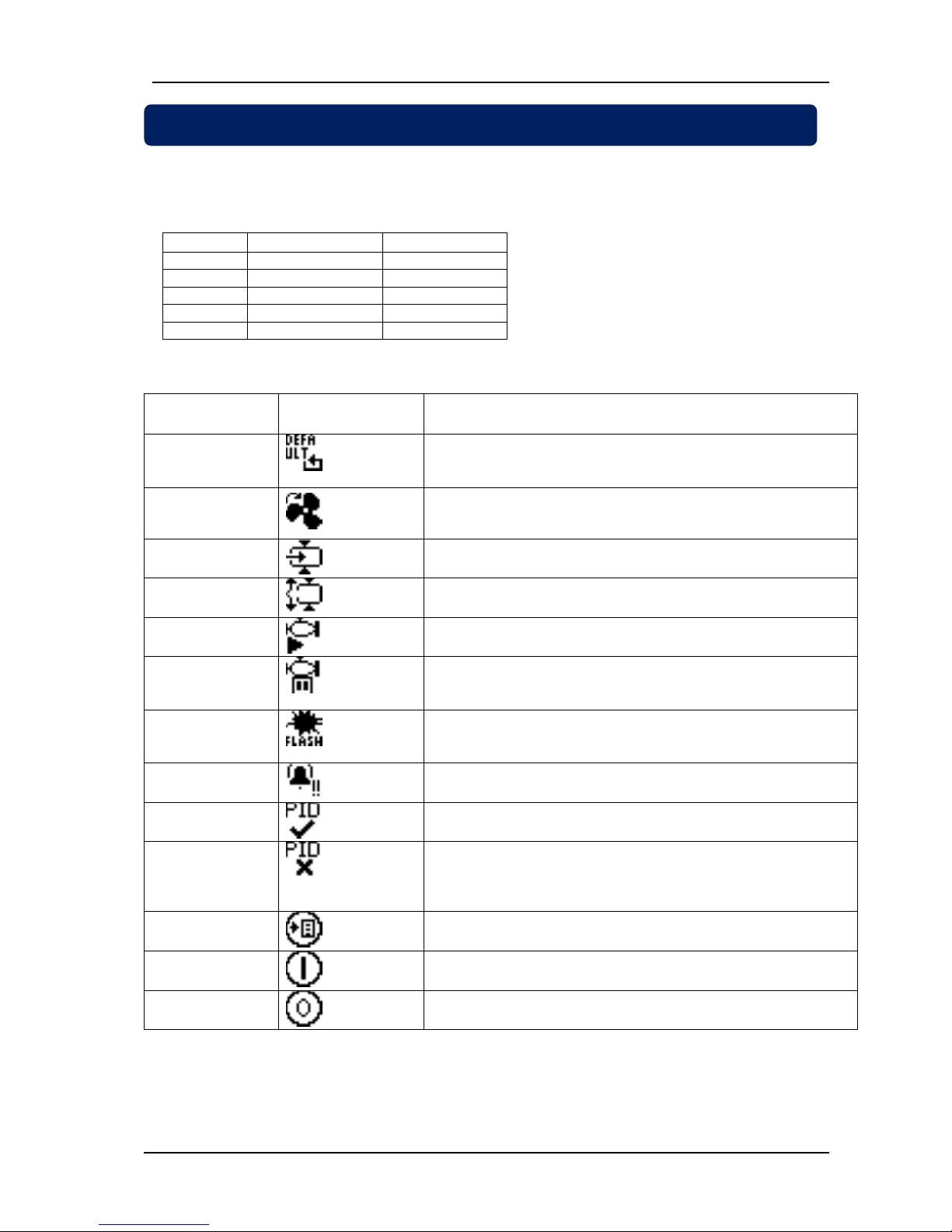
The unit provides 5 relay outputs with fully programmable functions.
The factory set values of relay functions and related program parameters are shown in below table:
RELAY #
FACTORY SET
PROGRAM #
RL 1
Main relay
D.06
RL 2
Delta relay
D.07
RL 3
Star relay
D.08
RL 4
Load relay
D.09
RL 5
Alarm relay
D.01
RELAY FUNCTION LIST:
PARAMETER
VALUE
FUNCTION
DESCRIPTION
0
DEFAULT
Relay adjusted to “FACTORY DEFAULT” function.
1
FAN
Operates when the temperature measured from the first
temperature sensor is higher than E.34.Releases when lower
than (E.34-E.35).
2
LOAD
Load relay
3
NO LOAD
Inverse of load relay
4
MOTOR
Operates when the motor is running, releases when the motor is
stopped.
5
MOTOR STOP
Operates when the motor is stopped, releases when the motor
is running.
6
FLASHING RELAY
Released during E.36 timer
Operates during E.37 timer.
7
ALARM
Operates when there is an alarm.
8
PID ACTIVE
Operates when the PID is active.
9
FORCE TO MIN
(PID INACTIVE)
Operates when PID is not active.
10
BUTTON 1
Operates when button_1 (MENU) is pressed.
11
BUTTON 2
Operates when button_2 (START) is pressed.
12
BUTTON 3
Operates when button_3 (STOP) is pressed.
9. RELAY OUTPUTS
Page 34
DK-45 Kullanım Kılavuzu V1.0 (22.09.2016)
- 34 -
The program menu is protected by a 2 level password system. Parameter set and password levels
may differ following compressor manufacturers. This document is based on factory set parameter list.
Entering the program menu:
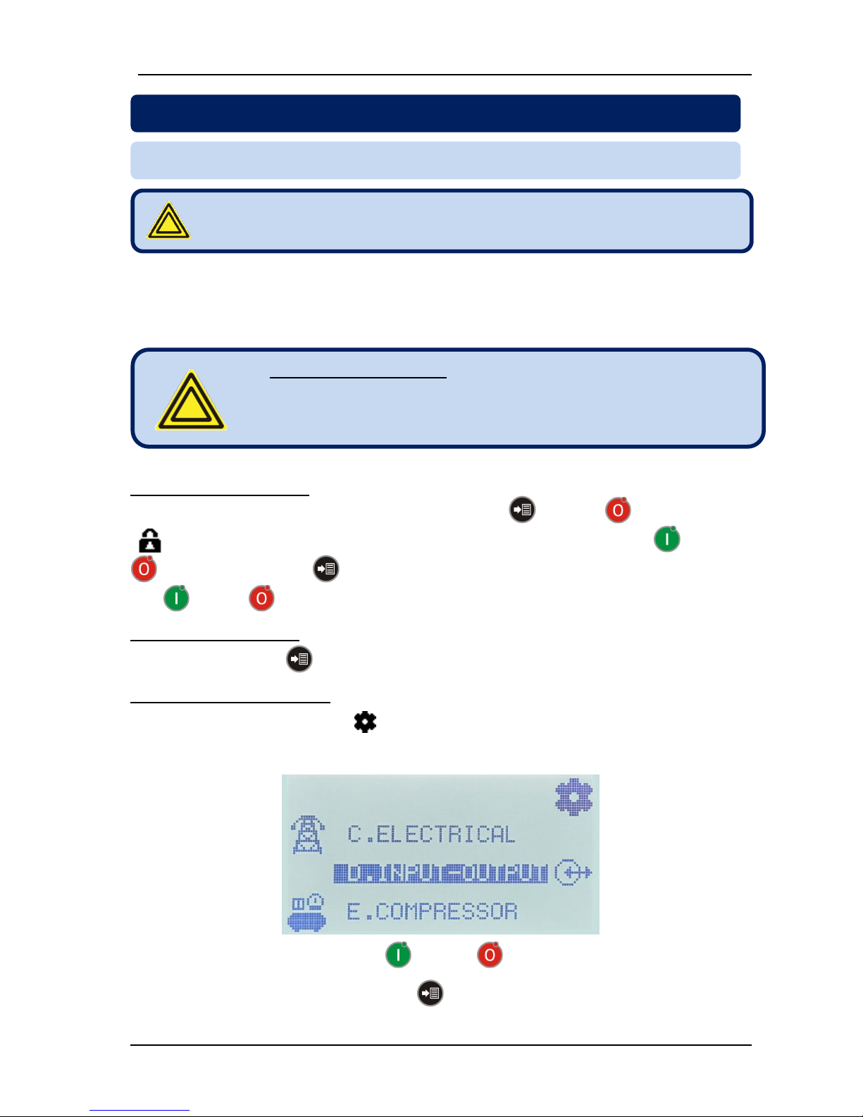
- When the compressor is in STOP MODE, hold pressed MENU and STOP buttons 3 seconds.
- (enter password) icon will appear on top of display. Enter the password using RUN and STOP
buttons and press MENU button. In order to increase/decrease the value faster you can hold
RUN or STOP buttons pressed.
Exiting the program menu:
- Hold pressed the MENU button for 3 seconds.
Modifying program parameters:
- When program mode is entered, the (programming) icon appears on top-right of the screen. Below
comes parameter groups. Selected parameter group is displayed with a black background. The icon
appearing on the left side when the parameter is not selected, moves to the right when it is selected.
- Determine the parameter group with RUN and STOP buttons.
- Enter into the parameter group with the MENU button.
10. PROGRAMMING
10.1. ENTERING THE PROGRAMMING MODE
Program menu can be selected only when the compressor is in
STOP mode.
Factory set passwords:
Low level password = 1
High level password = 2
Page 35
DK-45 Kullanım Kılavuzu V1.0 (22.09.2016)
- 35 -
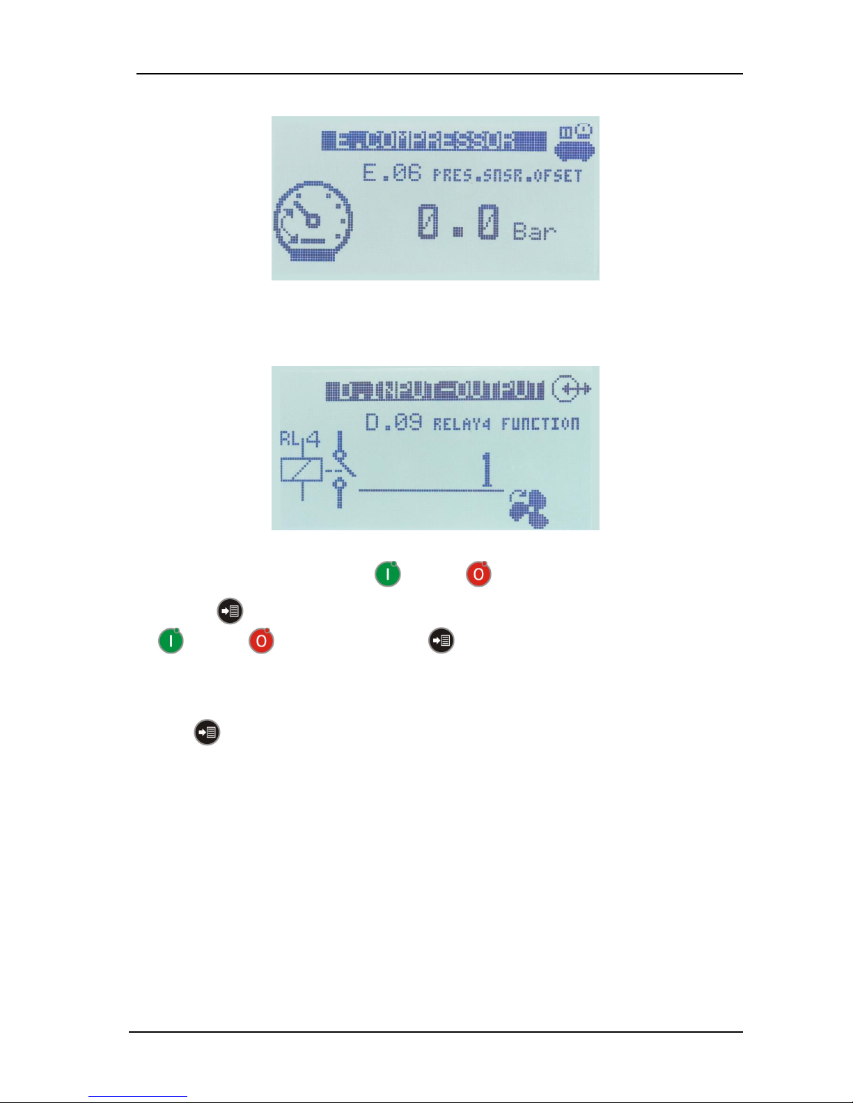
- When inside a parameter group, the group name and icon will be displayed on top of screen. Below will
come the code and name of the parameter. If the parameter has a unit, it will be displayed together with
the parameter value.
If the parameter has a descriptive icon, it will be displayed at the bottom right of the parameter value.
- Select the parameter to modify with RUN and STOP buttons.
- Press MENU button to make the parameter value underlined. Adjust parameter value with
RUN and STOP buttons and press MENU button to remove the underline.
If the parameter before the first one or after the last one is selected, the parameter group menu will be
resumed.
In order to return to upper parameter group screen or exit the programming menu please hold pressed
the MENU button during 3 seconds.
Page 36
DK-45 Kullanım Kılavuzu V1.0 (22.09.2016)
- 36 -
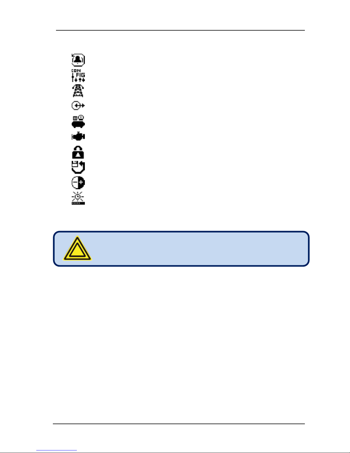
Programlama konumundaki parametre grupları sırasıyla şunlardır:
A.ALARM HISTRY (Alarm history)
B.CONFIGURATION (Configurations)
C.ELECTRICAL (Electrical parameters)
D.INPUT-OUTPUT (Input-Output parameters)
E.COMPRESSOR (Compressor parameters)
F.MOTOR (Motor parameters)
G.PASSWORD (Change password)
H.RETURN/SAVE (Return/Save to factory settings or set values)
K.LCD CONTRAST (LCD contrast)
L.BACKLIGHT (LCD backlight timer)
When no action is taken during 1 minute, the upper menu will
be automatically selected. If the main programming menu is
selected then programming mode will be exited.
Page 37
DK-45 Kullanım Kılavuzu V1.0 (22.09.2016)
- 37 -
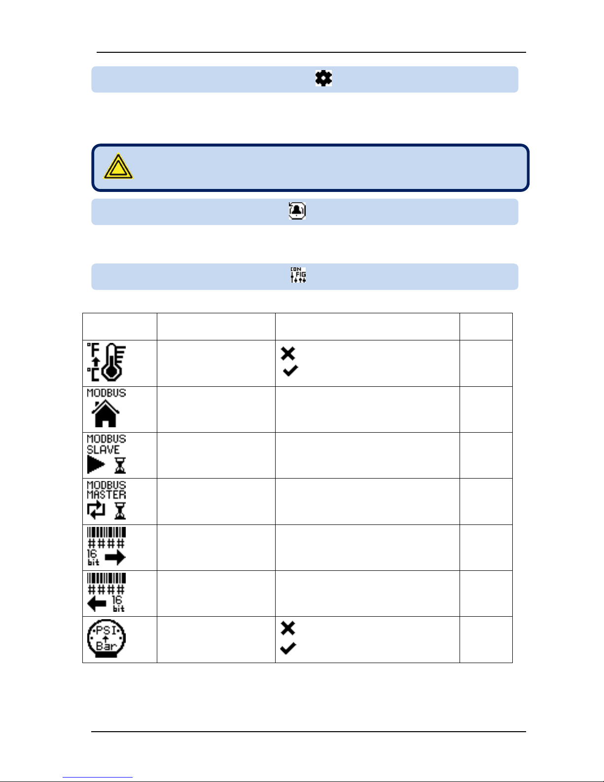
Below is the list of all possible parameters. The description section gives first the parameter name in
uppercase letters as it appears on the screen, then the description of it in lowercase letters.
Please see chapter 6.6.
ICON and No:
DESCRIPTION
ADJUSTMENT LIMITS
Factory
Set
B.01
DISP TEMP.IN F :
Display temperature in
degrees F.
0:Celcius
1:Fahrenheit
0
B.02
MODBUS ADDRESS :
1: Starts multi-compressor operation
2... 254: Modbus address
9
B.03
TIMETO.SLV.STRT :
Slave start timer
(Multi-compressor)
1...999 sec
11 sec
B.04
MASTER CH.TIM :
Master change timer
(Multi-compressor)
0.1 ... 999.9 hour
4.0 hour
B.05
SERI.NO.LOW WRD :
Serial number (lower 16
bits)
0 ... 65535
10
B.06
SERI.NOHGH WRD :
Serial number (higher 16
bits)
0 ... 65535
10
B.07
SHOW PSI :
Show pressure in PSI
0: pressure displayed in bars
1: pressure displayed in PSI
0
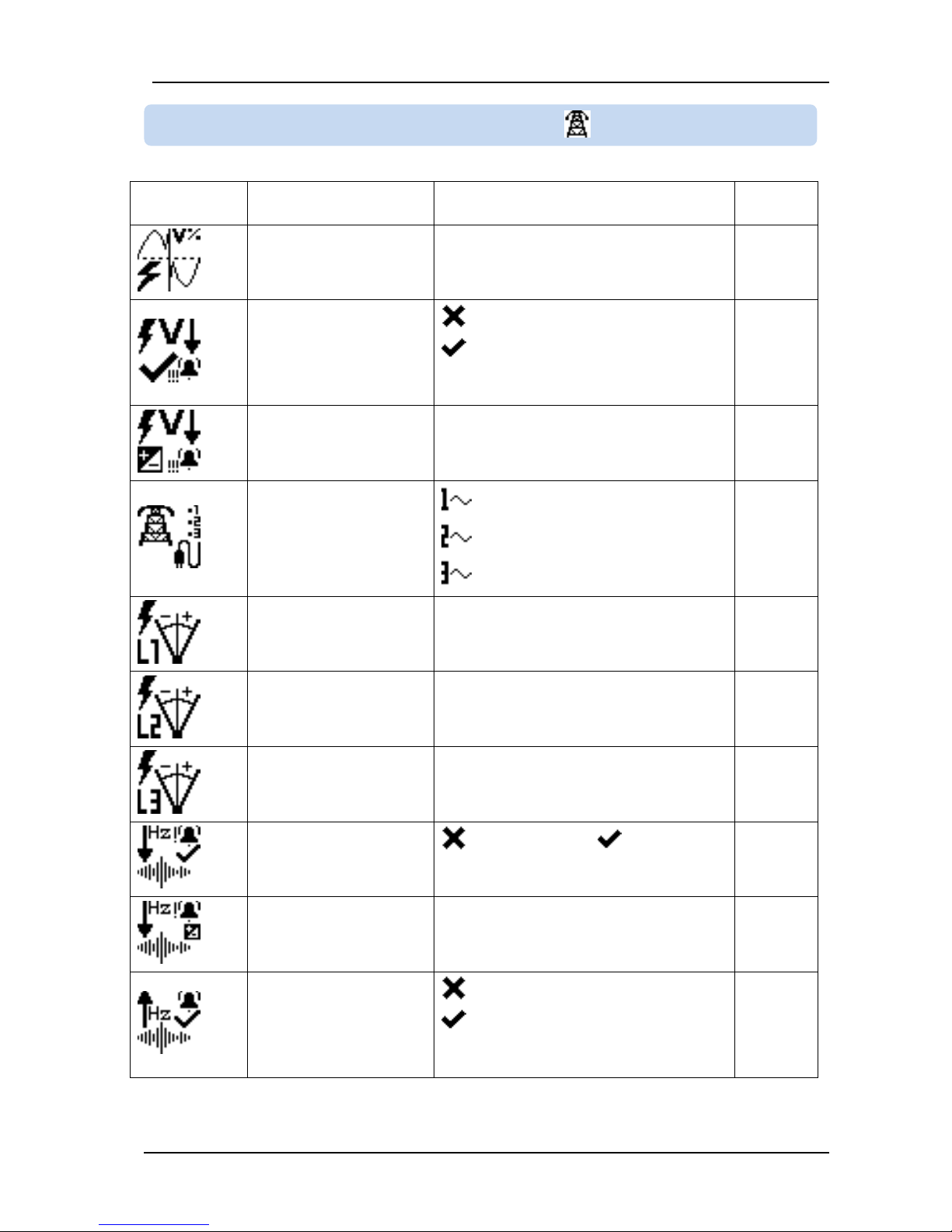
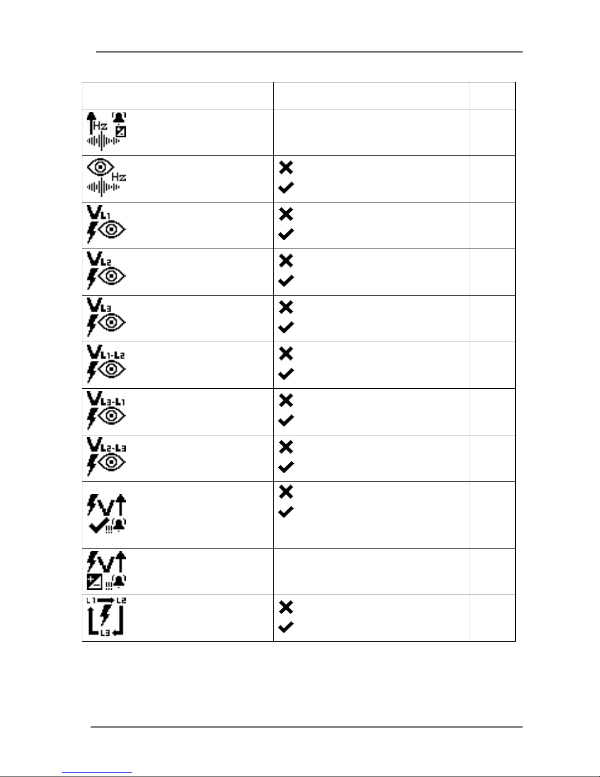
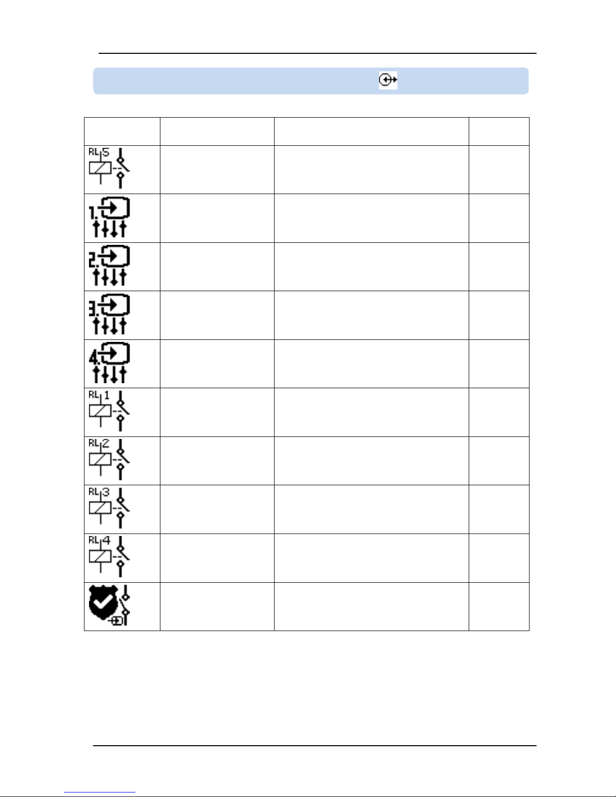
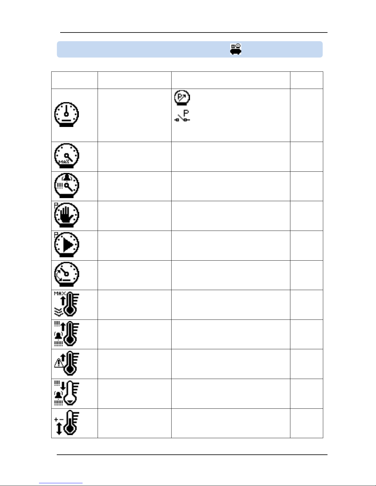
10.2. LIST OF PARAMETERS
Some of the parameters in this list may not apeear on the
controller.
10.2.1. ALARM HISTORY
10.2.2. CONFIGURATION
Page 38
DK-45 Kullanım Kılavuzu V1.0 (22.09.2016)
- 38 -
ICON and No:
DESCRIPTION
ADJUSTMENT LIMITS
Factory
Set
C.01
VOLT.UNBALANCE % :
Voltage unbalance ratio
% 0 ... 20
5 %
C.02
LOW VOLT. ALARM :
Low voltage alarm enable
0: disabled
1: enabled
If this parameter is set to 0 then the
parameter C.03 will not be visible.
1
C.03
LOW VOLT. ALARM :
Low voltage alarm limit
100 ... 600
360 V-AC
C.04
WIRING TOPOLOGY :
1: Single phase
2: Two phased
3: Three phased
3
C.05
PHASE L1 CONSTNT :
Phase L1 calibration
coefficient
1 ... 32767
1219
C.06
PHASE L2 CONSTNT :
Phase L2 calibration
coefficient
1 ... 32767
1219
C.07
PHASE L3 CONSTNT :
Phase L3 calibration
coefficient
1 ... 32767
1219
C.08
LOW FREQ. ALARM :
Low frequency alarm
enable
0: disabled 1: enabled
If this parameter is set to 0 then the
parameter C.09 will not be visible.
1
C.09
LOW FREQ. ALARM :
Low frequency alarm limit
10.0 ... 60.0
48.0 Hz
C.10
HIGH FREQ.ALARM:
High frequency alarm
enable
0: disabled
1: enabled
If this parameter is set to 0 then the
parameter C.11 will not be visible.
1
10.2.3. ELECTRICAL PARAMETERS
Page 39
DK-45 Kullanım Kılavuzu V1.0 (22.09.2016)
- 39 -
ICON and No:
DESCRIPTION
ADJUSTMENT LIMITS
Factory
Set
C.11
HIGH FREQ.ALARM:
High frequency alarm limit
50.0 ... 990.0 Hz
62.0
C.12
DISPLAY FREQ :
Display frequency
0: no
1: yes
1
C.13
DISPLAY VOLT. L1 :
Display voltage L1
0: no
1: yes
0
C.14
DISPLAY VOLT. L2 :
Display voltage L2
0: no
1: yes
0
C.15
DISPLAY VOLT. L3 :
Display voltage L3
0: no
1: yes
0
C.16
DISPLY.VOLT. L12 :
Display voltage L1-L2
0: no
1: yes
1
C.17
DISPLY.VOLT. L23 :
Display voltage L2-L3
0: no
1: yes
1
C.18
DISPLY.VOLT. L31 :
Display voltage L3-L1
0: no
1: yes
1
C.19
HIGH VOLT.ALARM :
High voltage alarm enable
0: disabled
1: enabled
If this parameter is set to 0 then the
parameter C.20 will not be visible.
1
C.20
HIGH VOLT.ALARM :
High voltage alarm limit
100 ... 650 V
445
C.21
PHASE SEQUENCE :
Phase sequence check
enable
0: disabled
1: enabled
1
Page 40
DK-45 Kullanım Kılavuzu V1.0 (22.09.2016)
- 40 -
ICON and No:
DESCRIPTION
ADJUSTMENT LIMITS
Factory
Set
D.01
RELAY5 FUNCTION :
0 ... 12 (see chapter 9)
0
D.02
INPUT-1 CONTROL :
Input_1 configuration
0 ... 2047
Please see chapter 8 for details.
18
D.03
INPUT-2 CONTROL :
Input_2 configuration
0 ...2047
Please see chapter 8 for details.
28+512=54
0
D.04
INPUT-3 CONTROL :
Input_3 configuration
0 ... 2047
Please see chapter 8 for details.
8+512=520
D.05
INPUT-4 CONTROL :
Input_4 configuration
0 ... 2047
Please see chapter 8 for details.
16+256+=1
808
D.06
RELAY1 FUNCTION :
0 ... 12 (see chapter 9)
0
D.07
RELAY2 FUNCTION :
0 ... 12 (see chapter 9)
0
D.08
RELAY3 FUNCTION :
0 ... 12 (see chapter 9)
0
D.09
RELAY4 FUNCTION :
0 ... 12 (see chapter 9)
0
D.10
SEC. INPUT FUNC. :
Güvenlik girişi siviçi
fonksiyon seçimi
1 ... 255
1
10.2.4. INPUT-OUTPUT PARAMETERS
Page 41
DK-45 Kullanım Kılavuzu V1.0 (22.09.2016)
- 41 -
ICON and No:
DESCRIPTION
ADJUSTMENT LIMITS
Factory
Set
E.01
PRESS. CONTROL :
Pressure sensor type
0: Analog sensor connected
1: Pressure switch connected
If this parameter is set to 1 then parameters
E.02 ... E.06 will not be visible.
0
E.02
PRESS.TOP RANGE :
Pressure upper display
limit
1.7... 99.9
15.0 bar
E.03
HIGH PRES.ALARM :
High pressure alarm limit
(E.02-0.5) ... (E.04+0.2)
8.5 bar
E.04
STOP PRESSURE :
(E.03-0.2) ... (E.05+0.2)
7.4 bar
E.05
START PRESSURE :
0.5 ... (E.04-0.2)
6.5 bar
E.06
PRES.SNSR.OFSET :
Pressure sensor offset
adjustment
-2.0 ... +2.0
0.0 bar
E.07
TEMP. TOP RANGE :
Temperature display
upper limit
(E.08+2) ... 130
130 °C
E.08
HIGH TEMP.ALARM :
High outlet temperature
alarm limit
(E.09+2) ... (E.07-2)
108 °C
E.09
HIGH TEMP.WARNG :
High outlet temperature
warning limit
(E.10+2) ... (E.08-2)
103 °C
E.10
LOW TEMP. ALARM :
Low outlet temperature
alarm limit
-10 ... (E.09-2)
0 °C
E.11
TEMP. OFFSET :
Temperature sensor
offset adjustment
-10 ... +10
0 °C
10.2.5. COMPRESSOR PARAMETERS
Page 42
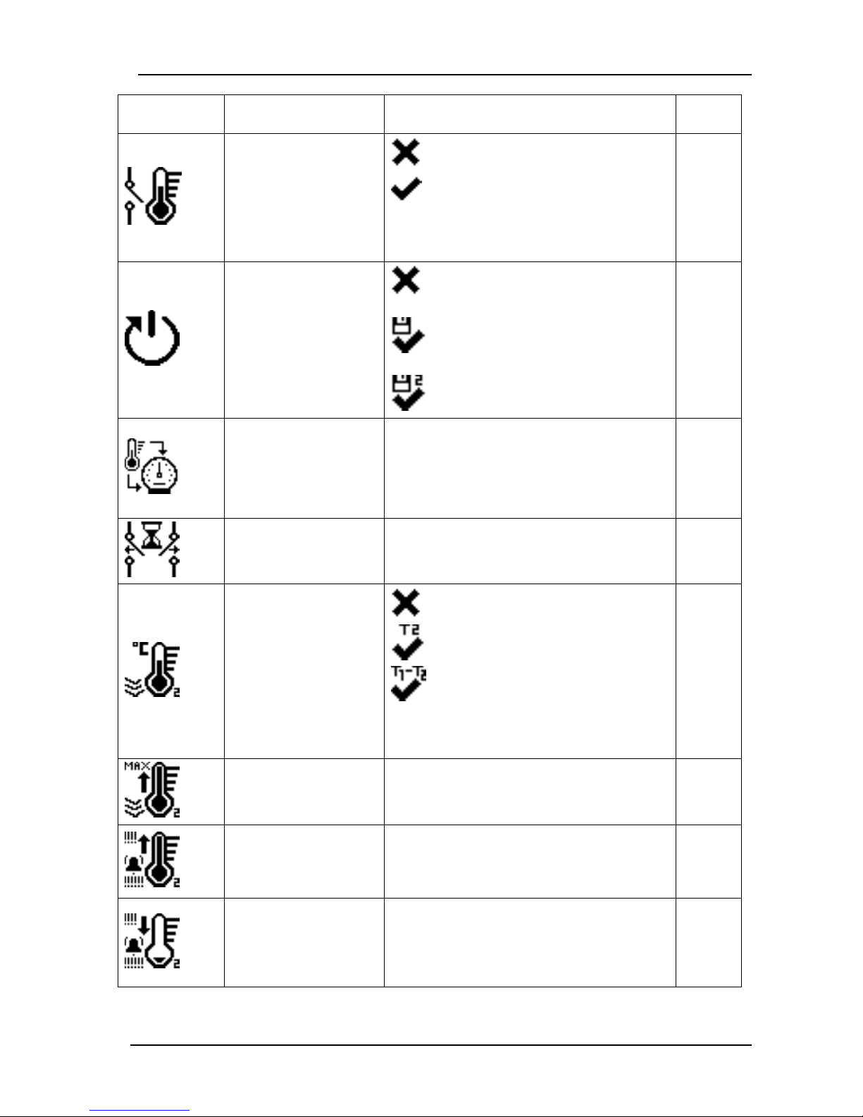
DK-45 Kullanım Kılavuzu V1.0 (22.09.2016)
- 42 -
ICON and No:
DESCRIPTION
ADJUSTMENT LIMITS
Factory
Set
E.12
MOTOR PTC :
Motor PTC connection
0: Not connected
1: Connected
If this sensor type is selected, when the sensor
impedance is over 2000 ohms, the ALARM 09
Motor PTC High Temperature will occur.
0
E.13
AUTO. RESTART :
Automatic restart
0: No (controller turns on at STOP
mode)
1: Yes (controller turns on at the last
mode)
2: Automatic restart (PORO)
0
E.14
CMPNS.PRES.TEMP. :
Pressure compensation
temperature
0 ... (E.09)
Until outlet air temperature reaches this level,
instead of E.04 Stop Pressure, E.05+(E.04E.05)/4 will be used.
Thus the compressor will stop before reaching
the stop pressure.
0 °C
E.15
DELAY BETWN.REL :
Delay between relays
20 ... 250 ms
This is the minimum period between release of
a relay and operation of another relay.
100 ms
E.16
TEMP.-2 SENSOR :
Temperature sensor 2
operation type
0: Not connected
1: Reads absolute temperature
2: Reads differential temperature
If this parameter is set to 0 then parameters
E.17, E.18, E.19, E.20 and E.21 will not be
visible.
0
E.17
TEMP.-2 TOP :
Temperature 2 display
upper limit
(E.18+2) ... 200
130 °C
E.18
TEMP-2 HGH ALRM :
High temperature 2
alarm limit (differential
temperature alarm limit)
(E.19+2) ... (E.17-2)
(Differential alarm limit)
110 °C
E.19
TEMP-2 LOW ALRM
Low temperature 2
alarm limit (differential
temperature warning
limit)
-40 ... (E.18-2)
(differential warning limit)
-10 °C
Page 43
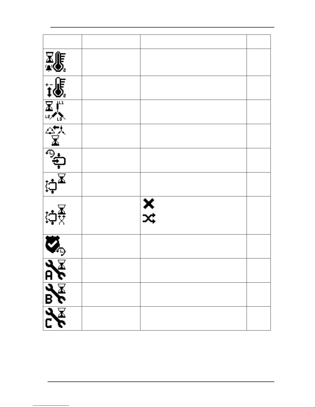
DK-45 Kullanım Kılavuzu V1.0 (22.09.2016)
- 43 -
ICON and No:
DESCRIPTION
ADJUSTMENT LIMITS
Factory
Set
E.20
T2 AL WRN TIME :
Temperature 2
alarm/warning automatic
reset delay
1 ... 600
10 sec
E.21
TEMP.-2 OFFSET :
Temperature sensor 2
offset adjustment
-10 ... +10
0 °C
E.22
STAR TIMER :
Star relay timer
2 ... 20
7 sec
E.23
STAR DELTA TIME :
Star / delta transition
timer
10 ... 50
15 ms
E.24
TIME BEFOR.LOAD :
Time before load
1 ... 999 Sec
2 sec
E.25
UNLOAD TIME :
0 ... 10
2 minute
E.26
VAR.UNLOAD TIME :
Variable unload timer
enable
0: Constant unload timer
1: Variable unload timer
Please see chapter 6.8 for details.
0
E.27
SAFETY TIMER :
Safety delay timer
1 ... 240
Please see chapter 4 for details.
30 sec
E.28
SERVICE A TIME :
Service A period
(Change air filter)
0 ...32767
If this parameter is set to 0 then service A
warning will not be given.
2000
hours
E.29
SERVICE B TIME :
Service B period
(Change oil filter)
0 ... 32767
If this parameter is set to 0 then service B
warning will not be given.
4000
hours
E.30
SERVICE C TIME :
Service C period
(Change separator filter)
0 ... 32767
If this parameter is set to 0 then service C
warning will not be given.
6000
hours
Page 44
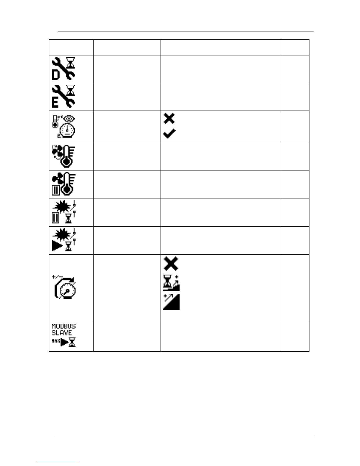
DK-45 Kullanım Kılavuzu V1.0 (22.09.2016)
- 44 -
ICON and No:
DESCRIPTION
ADJUSTMENT LIMITS
Factory
Set
E.31
SERVICE D TIME :
Service D period
(Change oil)
0 ... 32767
If this parameter is set to 0 then service D
warning will not be given.
10000
hours
E.32
SERVICE E TIME :
Service E period (Check
compresssor)
0 ... 32767
If this parameter is set to 0 then service E
warning will not be given.
20000
hours
E.33
DISP 2.TEMP PRS :
Display second
temperature and
pressure values
0: No
1: Yes
1
E.34
FAN ON TEMP. :
Fan turn-on temperature
30 ... (E.09-2)
Please see chapter 9 for details.
85 °C
E.35
FAN OFF TEMP. :
Fan turn-off differential
temperature
5 ... 15
Please see chapter 9 for details.
5 °C
E.36
FLASH OFF TIME :
Flashing relay off timer
0 ... 999
Please see chapter 9 for details.
2 sec
E.37
FLASH ON TIME :
Flashing relay on timer
0 ... 11999
Please see chapter 9 for details.
3 sec
E.38
PRVNT PRES.LOSS :
Pressure loss
prevention method
0: Standard operation
1: Increase/decrease after each cycle.
2: Calculation through pressure slope
Please see chapter 6.5 for details.
0
E.39
SLV.MAX RN TIME :
Slave compressor
maximum run time (multi
compressor)
0 … 65535
0 minute
Page 45
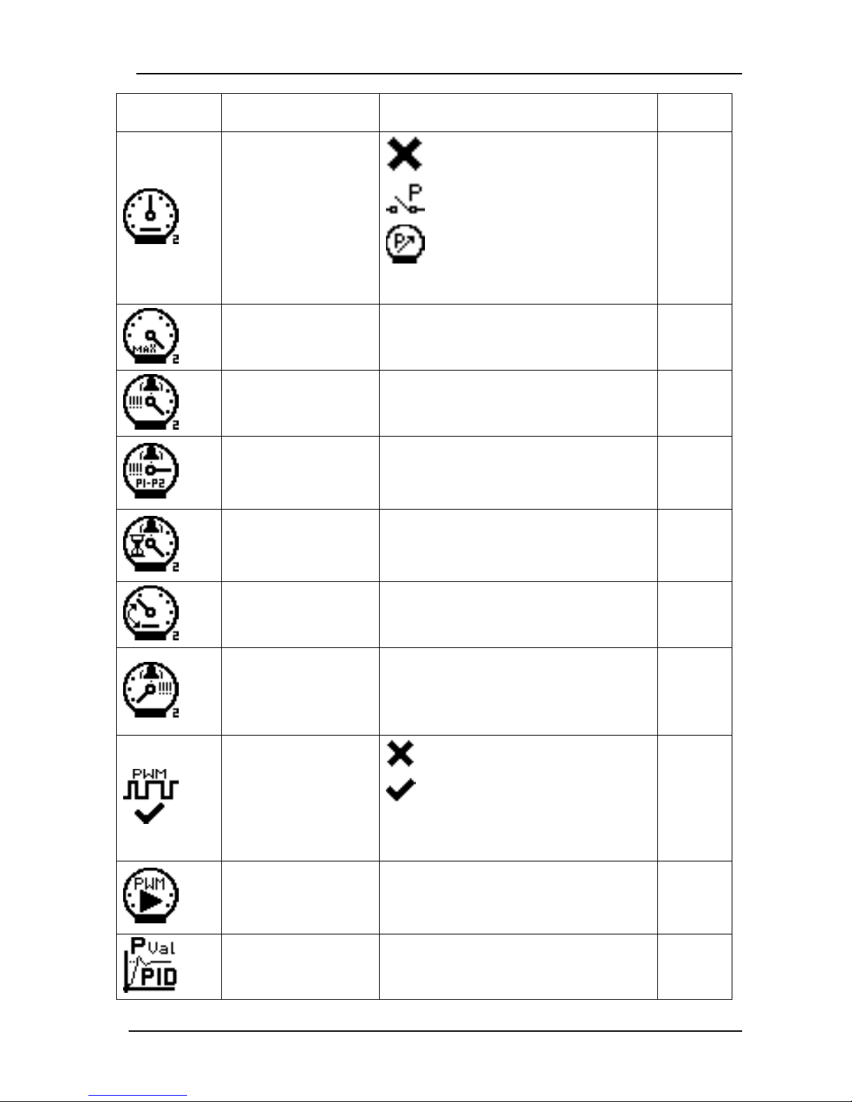
DK-45 Kullanım Kılavuzu V1.0 (22.09.2016)
- 45 -
ICON and No:
DESCRIPTION
ADJUSTMENT LIMITS
Factory
Set
E.40
PRES-2 SNSR.TYP :
Pressure 2 sensor type
0: not connected
1: Pressure switch connected
2: Analog sensor connected
If this parameter is set to 1 then parameters
E.41 ... E.45 will not be visible.
0
E.41
PRESS.-2 TOP :
Pressure 2 upper
display limit
1.7 ... 99.9 Bar
16.0 bar
E.42
HGH PRES-2 ALRM :
High pressure_2 alarm
limit
1.2 ... (E.41-0.5)
8.0 bar
E.43
DELTA.PRES.ALRM :
Differential pressure
alarm limit (Press1 –
Press2)
-10.0 ... +10.0
If the pressure difference P1-P2 stays over
this limit during E.44 period, then ALARM 20
High Differential Pressure is given.
0 bar
E.44
P2 ALARM DELAY :
Differential pressure
alarm delay timer
1 ... 600
If the pressure difference P1-P2 stays over
E.43 limit during this period, then ALARM 20
High Differential Pressure is given.
15 sec
E.45
P2 SENSOR.OFSET :
Pressure sensor 2 offset
adjustment
-2 ... +2
0 bar
E.46
LOW PRES-2 ALRM :
Air pressure sensor 2
low alarm limit. (Alarm
disabled when set to 0.0
bar)
0.0: alarm disabled
0.1... (E.42-0.5)
1 bar
E.47
MOTOR PWM SIGNL :
Analog (0-10V) motor
control signal enable
0: Disabled
1: Enabled
If this parameter is set to 0 then parameters
E.48, E.49, E.50, E.51, E.52, E.53 and E.54
will not be visible.
0
E.48
PWM SET PRESS. :
Analog (0-10V) motor
control signal set
pressure
0.5 ... (E.03-0.2)
7.0 bar
E.49
PID P VALUE :
PID control P gain
%0.0 ... 99.9
% 3.0
Page 46
DK-45 Kullanım Kılavuzu V1.0 (22.09.2016)
- 46 -
ICON and No:
DESCRIPTION
ADJUSTMENT LIMITS
Factory
Set
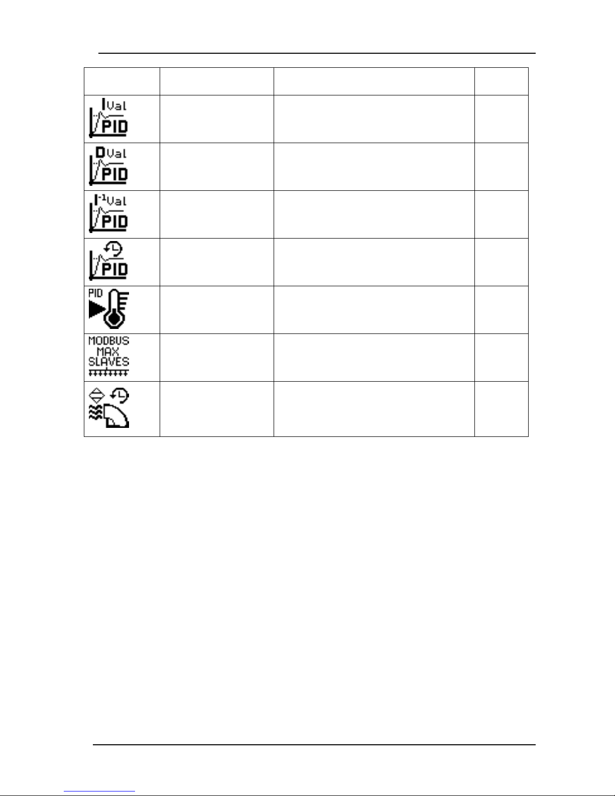
E.50
PID I VALUE :
PID control I gain
%0.0 ... 99.9
% 0
E.51
PID D VALUE :
PID control D gain
%0.0 ... 99.9
% 5.0
E.52
PID I INVRS VAL :
PID control inverse I
gain
%0.0 ... 99.9
% 0
E.53
PID CNTRL DELAY :
PID control activation
delay
1 ... 999 sec
Please see chapter 6.9 for details.
10 sec
E.54
PID START TEMP. :
PID control start
temperature
0 ... (E.08-2)
Please see chapter 6.9 for details.
15 °C
E.55
MAX SLAVES :
Maximum number of
slaves under load
0 ... 8
0
E.56
DRYER DLY.TIMER :
Dryer function delay
timer
0 ... 999 sec
If this parameter is set to 0 then the dryer
function is disabled.
Please see chapter 6.7 for details.
0 sec
Page 47
DK-45 Kullanım Kılavuzu V1.0 (22.09.2016)
- 47 -
ICON and No:
DESCRIPTION
ADJUSTMENT LIMITS
Factory
Set
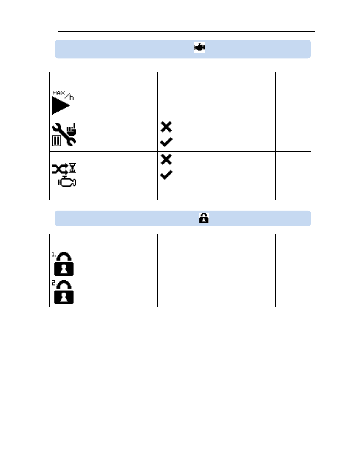
F.01
MAX STRTS PER H :
Maximum number of
starts allowed in one
hour
6 ... 240
20
F.02
STP.SRVC.RQUEST :
Service safety
selection
0: Warning only on service request
1:Operates as explained in chapter 5.1
0
F.03
MOTOR HOUR CAL :
Motor hours
calculation method
0: Constant coefficient
1: Variable coefficient
Please see chapter 6.3 for details.
0
ICON and No:
DESCRIPTION
ADJUSTMENT LIMITS
Factory
Set
G.01
LEVL 1 PASSWORD :
Low level password
0 ... 999
1
G.02
LEVL 2 PASSWORD :
High level password
0 ... 999
2
10.2.6. MOTOR PARAMETERS
10.2.7. PASSWORD CHANGING
Page 48
DK-45 Kullanım Kılavuzu V1.0 (22.09.2016)
- 48 -
ICON and No:
DESCRIPTION
ADJUSTMENT LIMITS
Factory
Set
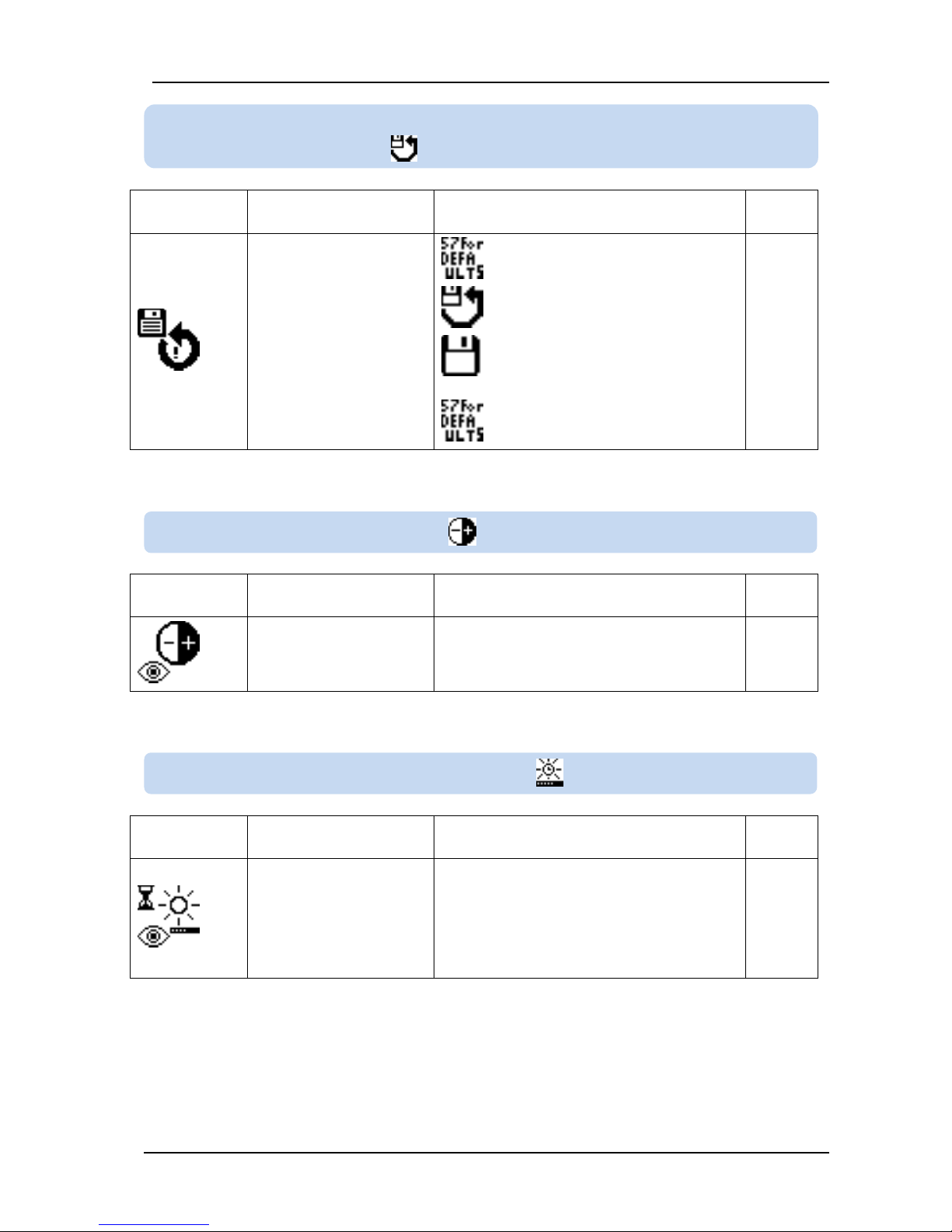
H.01
RETURN SAVE :
Return to restore values/
return to factory settings
0: no action
1: Return to restore point values
2: Save current parameter set as
restore point
57: Return to factory settings
0
ICON and No:
DESCRIPTION
ADJUSTMENT LIMITS
Factory
Set
K.01
LCD CONTRAST :
LCD contrast adjustment
25 ... 50
32
ICON and No:
DESCRIPTION
ADJUSTMENT LIMITS
Factory
Set
L.01
BACKLIGHT TIMER :
LCD backlight dimming
timer
0 ... 210 minutes
If no action happens and no button is
pressed during this timer, then LCD backlight
will turn off.
If this parameter is set to 0 then LCD
backlight never turns off. It is always on.
1 minute
10.2.8. RETURN/SAVE TO FACTORY SETTINGS OR SAVED
10.2.9. LCD CONTRAST
10.2.10. LCD BACKLIGHT TIMER
Page 49
DK-45 Kullanım Kılavuzu V1.0 (22.09.2016)
- 49 -
The unit offers the possibility of MODBUS communication through its serial port.
The serial port has 0/+5V logic levels.Using special adapters it is converted to RS-232 or RS-485
standards.
The MODBUS properties of the unit are:
-Data transfer mode: RTU
-Serial data: 9600 bps, 8 bit, no parity, 1 bit stop
-Supported functions:
-Function 3 (Read multiple registers, max 120 registers)
-Function 6 (Write single register)
-Function 16 (Write multiple registers, max 32 registers)
-Answer to a message is sent within 4.3ms after the reception of the querry.
Each register consists of 2 bytes (16 bits). A larger data structure will contain multiple registers.
Detailed description about the MODBUS protocol is found in the document “Modicon Modbus Protocol
Reference Guide”. This document may be downloaded at: www.modbus.org/docs/PI_MBUS_300.pdf
Each device in the same RS-485 serial network must be
assigned a different slave address. Otherwise the Modbus
communications will not be performed.
11. MODBUS COMMUNICATIONS
11.1. DESCRIPTION
Page 50
DK-45 Kullanım Kılavuzu V1.0 (22.09.2016)
- 50 -
Data reading
The function 03 (read multiple registers) will be used for data reading. The MODBUS master will send a
query. The answer will be one of the below:
-A response containing the requested data
-An exceptional response indicating a read error.
The maximum number of registers read in one message is 120. If more registers are requested, the unit
will send only the first 120 registers.
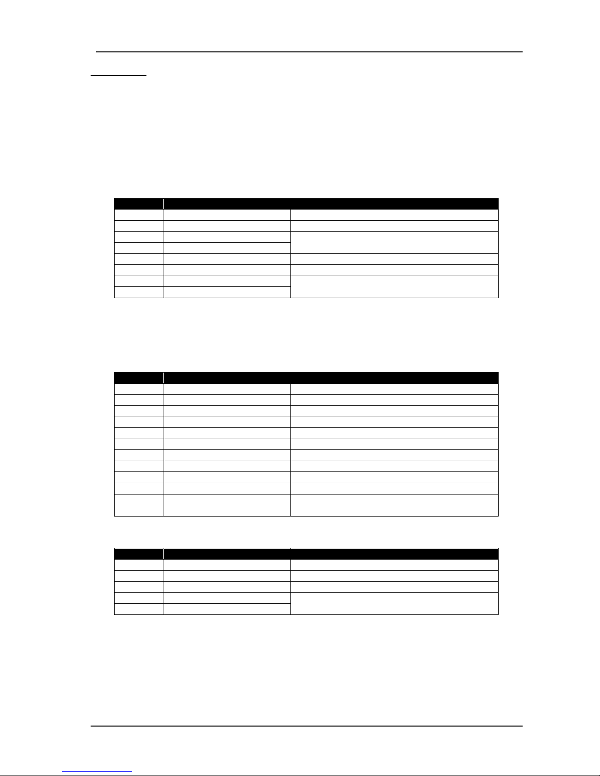
The query message specifies the starting register and quantity of registers to be read. The message
structure is below:
Byte
Description
Value
0
Controller address
254 1 Function code
3 2 Starting address high
See chapter 11.2 for the description of available
registers
3
Starting address low
4
Number of registers high
always 0
5
Number of registers low
max 78h (120 decimal)
6
CRC low byte
See below for the checksum calculation
7
CRC high byte
Here is the sequence to read 16 registers starting from address 20h (32 decimal):
01 03 00 20 00 10 45 CC (each byte is expressed as 2 hexadecimal characters)
The checksum value in the above message may be used for the verification of checksum
calculation algorithm.
The normal response will be:
Byte
Description
Value
0
Controller address
same as in the query
1
Function code
3
2
Data lenght in bytes (L)
number of registers * 2
3
High byte of 1st register
4 Low byte of 1st register
5 High byte of 2nd register
6 Low byte of 2nd register
....
L+1
High byte of the last register
L+2
Low byte of the last register
L+3
CRC low byte
See below for the checksum calculation
L+4
CRC high byte
The exceptional response will be:
Byte
Description
Value
0
Controller address
same as in the query
1
Function code
131 (function code + 128)
2
Exception code
2 (illegal address)
3
CRC low byte
See below for the checksum calculation
4
CRC high byte
Page 51
DK-45 Kullanım Kılavuzu V1.0 (22.09.2016)
- 51 -
Data Writing (single register)
The function 06 (write single register) and the function 16 (write multiple registers) are used for data
writing.
The MODBUS master will send a query containing data to be written. The answer will be one of the
below:
-A normal response confirming successful write,
-An exceptional response indicating a write error.
Only some of the available registers are authorized to be written. An attempt to write a write protected
register will result to the exceptional response.
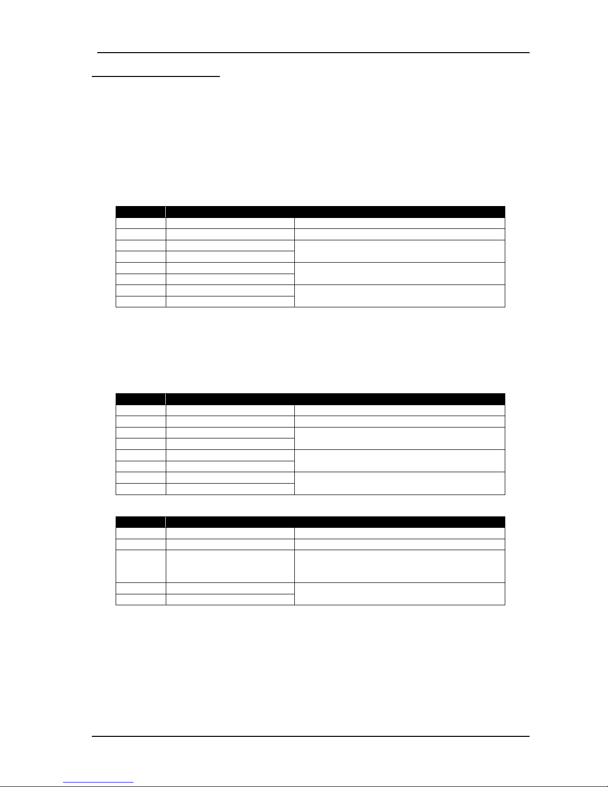
The query message specifies the register address and data. The message structure is below:
Byte
Description
Value
0
Controller address
1 to 254
1
Function code
6 2 Register address high
See below the description of available registers
3
Register address low
4
Data high byte
5
Data low byte
6
CRC low byte
See below for the checksum calculation
7
CRC high byte
Here is the sequence to write the value 0010h to the register 40h (64 decimal):
01 06 00 40 00 10 89 D2 (each byte is expressed as 2 hexadecimal characters)
The checksum value in the above message may be used for the verification of checksum calculation
algorithm
The normal response will be the same as the query:
Byte
Description
Value
0
Controller address
1 to 240
1
Function code
6 2 Register address high
See below the description of available registers
3
Register address low
4
Data high byte
5
Data low byte
6
CRC low byte
See below for the checksum calculation
7
CRC high byte
The exceptional response will be:
Byte
Description
Value
0
Controller address
same as in the query
1
Function code
134 (function code + 128)
2
Exception code
2 (illegal address)
or
10 (write protection)
3
CRC low byte
See below for the checksum calculation
4
CRC high byte
Page 52
DK-45 Kullanım Kılavuzu V1.0 (22.09.2016)
- 52 -
Data Writing (multiple register)
The function 06 (write single register) and the function 16 (write multiple registers) are used for data
writing.
The MODBUS master will send a query containing data to be written. The answer will be one of the
below:
-A normal response confirming successful write,
-An exceptional response indicating a write error.
Only some of the available registers are authorized to be written. An attempt to write a write protected
register will result to the exceptional response.
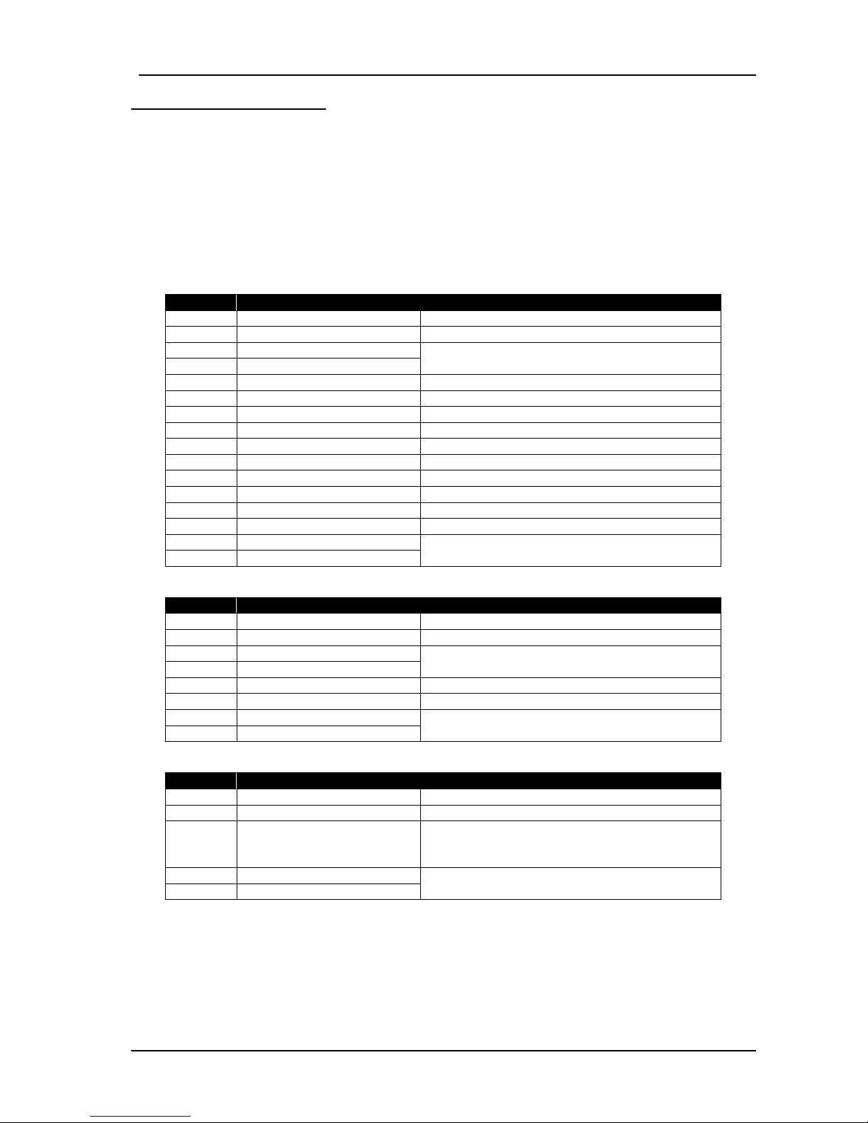
The query message specifies the register address and data. The message structure is below:
Byte
Description
Value
0
Controller address
1 to 254
1
Function code
16 2 Starting address high
See below the description of available registers
3
Starting address low
4
Number of registers high
always 0
5
Number of registers low
max 32
6
Data lenght in bytes (L)
number of registers * 2
7
High byte of 1st register
8 Low byte of 1st register
9 High byte of 2nd register
10
Low byte of 2nd register
....
L+5
High byte of the last register
L+6
Low byte of the last register
L+7
CRC low byte
See below for the checksum calculation
L+8
CRC high byte
The normal response is below:
Byte
Description
Value
0
Controller address
1 to 240
1
Function code
16 2 Starting address high
See below the description of available registers
3
Starting address low
4
Number of registers high
always 0
5
Number of registers low
max ??
6
CRC low byte
See below for the checksum calculation
7
CRC high byte
The exceptional response will be:
Byte
Description
Value
0
Controller address
same as in the query
1
Function code
144 (function code + 128)
2
Exception code
2 (illegal address)
or
10 (write protection)
3
CRC low byte
See below for the checksum calculation
4
CRC high byte
Page 53

DK-45 Kullanım Kılavuzu V1.0 (22.09.2016)
- 53 -
CRC calculation
Here is a procedure for generating a CRC:
1) Load a 16–bit register with FFFF hex (all 1’s). Call this the CRC register.
2) Exclusive OR the first 8–bit byte of the message (the function code byte) with the low–order byte of the
16–bit CRC register, putting the result in the CRC register.
3) Shift the CRC register one bit to the right (toward the LSB), zero–filling the MSB. Extract and examine
the LSB. The LSB is the least significant bit of the CRC before the shift operation.
4) If the LSB is 1: Exclusive OR the CRC register with the polynomial value A001 hex.
5) Repeat Steps 3 and 4 until 8 shifts have been performed. Thus, a complete 8–bit byte will be
processed.
6) Repeat Steps 2 through 5 for the next 8–bit byte of the message. Continue doing this until all bytes
have been processed.
7) The final contents of the CRC register is the CRC value.
8) Place the CRC into the message such that the low byte is transmitted first. The algorithm should give
the correct CRC for below messages:
01 03 00 20 00 10 45 CC
01 06 00 40 00 10 89 D2
Error codes
Only 3 error codes are used:
01: illegal function code
02: illegal address
10: write protection (attempt to write a read_only register)
Data types
Each register consists of 16 bits (2 bytes)
If the data type is a byte, only the low byte will contain valid data. High byte is don’t care.
For data type longer than 16 bits, consecutive registers are used. The least significant register
comes first.
Data formats
16bit variables: These variables are stored in a single register. Bit_0 denotes the LSB and bit 15
denotes the MSB.
32 bit variables: These variables are stored in 2 consecutive registers. The high order 16 bits are in the
first register and the low order 16 bits are in the second register
Bit arrays: Arrays larger than 16 bits are stored in multiple registers. The LSB of the first register is bit_0.
The MSB of the first register is bit_15. The LSB of the second register is bit_16. The MSB of the second
register is bit_31, and so on.
Page 54
DK-45 Kullanım Kılavuzu V1.0 (22.09.2016)
- 54 -
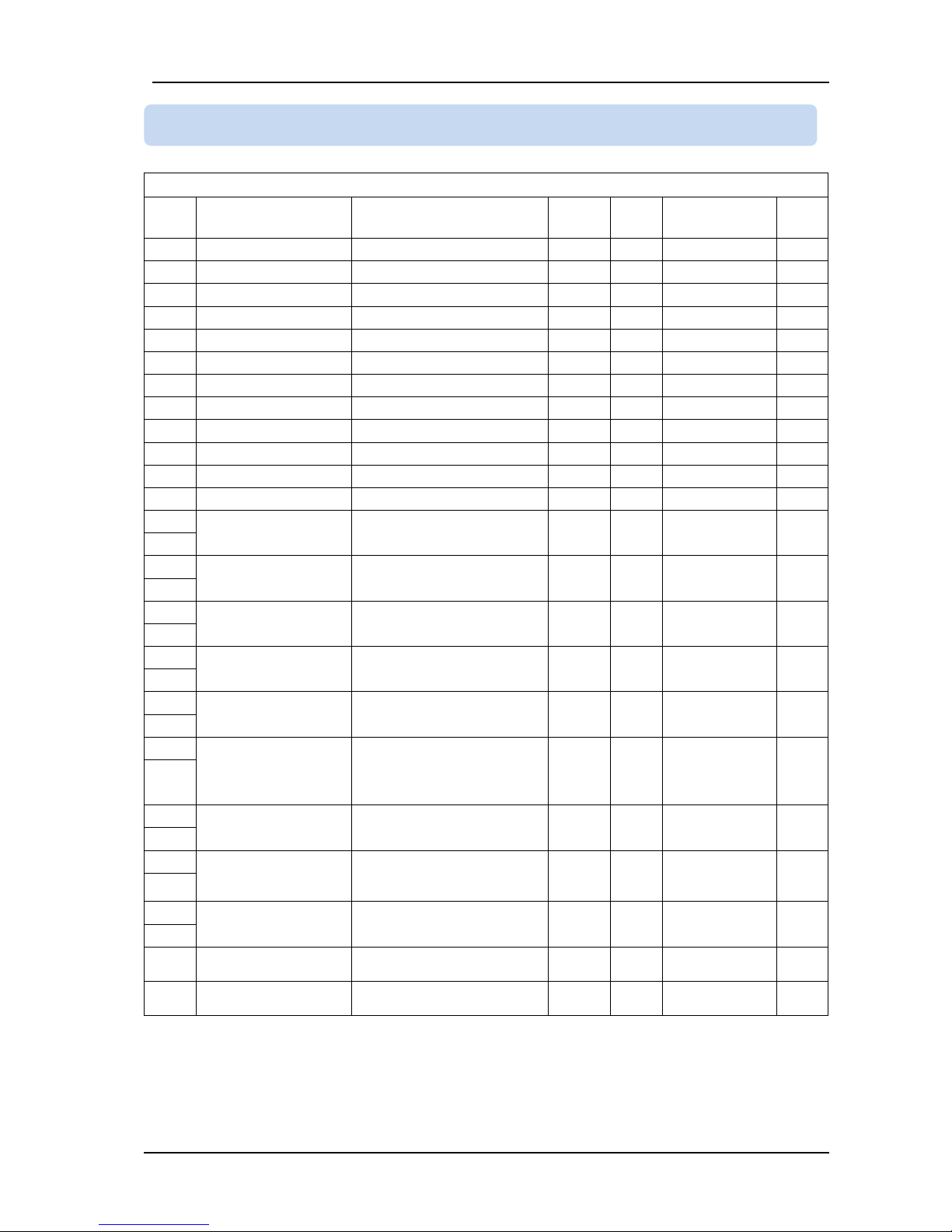
CONTROLLER REGISTERS
ADDR.
NAME
DESCRIPTION
LENGTH
READ/
WRITE
DATA TYPE
COEFF
40001
Frequency
16 BIT
R-O
unsigned word
0.1
40002
Voltage phase L1
16 BIT
R-O
unsigned word
1
40003
Voltage phase L2
16 BIT
R-O
unsigned word
1
40004
Voltage phase L3
16 BIT
R-O
unsigned word
1
40005
Voltage phase L1-L2
16 BIT
R-O
unsigned word
1
40006
Voltage phase L2-L3
16 BIT
R-O
unsigned word
1
40007
Voltage phase L3-L1
16 BIT
R-O
unsigned word
1
40008
Pressure
16 BIT
R-O
unsigned word
0.1
40009
Temperature
16 BIT
R-O
signed word
1
40010
Motor PTC ohms
Reads in ohms
16 BIT
R-O
signed word
1
40011
Temperature-2
Read from temp sensor-2
16 BIT
R-O
signed word
1
40012
Pressure-2
Read from press. Sensor-2
16 BIT
R-O
unsigned word
0.1
40013
Service A counter
Time to service-A
32 BIT
R-O
signed long
0.1
40014
40015
Service B counter
Time to service-B
32 BIT
R-O
signed long
0.1
40016
40017
Service C counter
Time to service-C
32 BIT
R-O
signed long
0.1
40018
40019
Service D counter
Time to service-D
32 BIT
R-O
signed long
0.1
40020
40021
Service E counter
Time to service-E
32 BIT
R-O
signed long
0.1
40022
40023
Total run hours
On_load+off_LOAD+STOP
the total time the
compressor has run or has
waited ready to run
32 BIT
R-O
unsigned long
0.1
40024
40025
Total motor hours
On_load+off_LOAD the total
time the compressor has run
32 BIT
R-O
unsigned long
0.1
40026
40027
Total load hours
the total time the
compressor has run
on_LOAD
32 BIT
R-O
unsigned long
0.1
40028
40029
Alarms
Alarm bits
List is given in chapter 11.3
32 BIT
R-O
unsigned long
1
40030
40031
Warnings
Warning bits
List is given in chapter 11.3
16 BIT
R-O
unsigned word
1
40032
Service request
Service request bits
List is given in chapter 11.3
16 BIT
R-O
unsigned word
1
11.2. MODBUS REGISTER LIST
Page 55
DK-45 Kullanım Kılavuzu V1.0 (22.09.2016)
- 55 -
CONTROLLER REGISTERS
ADDR.
NAME
DESCRIPTION
LENGTH
READ/
WRITE
DATA TYPE
COEFF
40033
Motor status
Current status of the motor
0: Compressor STOP mode
1: Motor in star run
2: Motor in delta (off_load)
3: Motor in delta (on_load)
4: Unload timer
5: Motor stopped,
compressor in RUN mode
16 BIT
R-O
unsigned word
1
40034
Last fault code
Currently active alarm,
warning or service request
code.
Fault code list is given in
chapter 5.
16 BIT
R-O
unsigned word
1
40035
Relay outputs
Current status of relays:
bit 1-3:bit 4: RL1
bit 5: RL5
bit 6: RL4
bit 7: RL2
bit 8: RL3
bit 9-16: -
16 BIT
R-O
unsigned word
1
40036
- - 16 BIT
R-O
unsigned word
1
40037
Alarm 1
Alarm #1 in alarm history
16 BIT
R-O
unsigned word
1
40038
Alarm 2
Alarm #2 in alarm history
16 BIT
R-O
unsigned word
1
40039
Alarm 3
Alarm #3 in alarm history
16 BIT
R-O
unsigned word
1
40040
Alarm 4
Alarm #4 in alarm history
16 BIT
R-O
unsigned word
1
40041
Alarm 5
Alarm #5 in alarm history
16 BIT
R-O
unsigned word
1
40042
Alarm 6
Alarm #6 in alarm history
16 BIT
R-O
unsigned word
1
40043
Alarm 7
Alarm #7 in alarm history
16 BIT
R-O
unsigned word
1
40044
Alarm 8
Alarm #8 in alarm history
16 BIT
R-O
unsigned word
1
40045
Alarm 9
Alarm #9 in alarm history
16 BIT
R-O
unsigned word
1
40046
Utility mains topology
1:one phase 2:two phases
3: three phase
16 BIT
R-O
unsigned word
1
40047
0-10 V output
Output analog value
(0-1023)
16 BIT
R-O
unsigned word
1
40048
- 16 BIT
R-O
unsigned word
1
40049
- 16 BIT
R-O
unsigned word
1
40050
- 16 BIT
R-O
unsigned word
1
40051
- 16 BIT
R-O
unsigned word
1
40052
- 16 BIT
R-O
unsigned word
1
40053
- 16 BIT
R-O
unsigned word
1
40054
LEDs
LED statuses
16 BIT
R-O
unsigned word
1
40055
% Load
Load percentage
16 BIT
R-O
unsigned word
1
40056
Master address
Modbus address of master
16 BIT
R-O
unsigned word
1
40057
Number of controllers
Number of controllers in
multi compressor
16 BIT
R-O
unsigned word
1
40058
Requests
Start Stop request
16 BIT
R-O
unsigned word
1
Page 56
DK-45 Kullanım Kılavuzu V1.0 (22.09.2016)
- 56 -
CONTROLLER REGISTERS
ADDR.
NAME
DESCRIPTION
LENGTH
READ/
WRITE
DATA TYPE
COEFF
40059
Flashing counter
Flashing relay counter value
32 BIT
R-O
unsigned dword
2
40060
40061
Active flashing relays
Number of active flashing
relays
16 BIT
R-O
unsigned word
1
40062
Flashing number
Total number of flashing
relays
16 BIT
R-O
unsigned word
1
40063
Firmware version
Controller software version
16 BIT
R-O
unsigned word
1
40064
-
40128
reserved
-
16 BIT
R-O
unsigned word
1
PROGRAM PARAMETERS
ADDR.
NAME
DESCRIPTION
LENGTH
READ/
WRITE
DATA TYPE
COEFF
.
40129
E.01
Explained in chapter 10.2
16 BIT
R/W
unsigned word
1
40130
E.02
Explained in chapter 10.2
16 BIT
R/W
unsigned word
0.1
40131
E.03
Explained in chapter 10.2
16 BIT
R/W
unsigned word
0.1
40132
E.04
Explained in chapter 10.2
16 BIT
R/W
unsigned word
0.1
40133
E.05
Explained in chapter 10.2
16 BIT
R/W
unsigned word
0.1
40134
E.06
Explained in chapter 10.2
16 BIT
R/W
signed word
0.1
40135
E.07
Explained in chapter 10.2
16 BIT
R/W
signed word
1
40136
E.08
Explained in chapter 10.2
16 BIT
R/W
signed word
1
40137
E.09
Explained in chapter 10.2
16 BIT
R/W
signed word
1
40138
E.10
Explained in chapter 10.2
16 BIT
R/W
signed word
1
40139
E.11
Explained in chapter 10.2
16 BIT
R/W
signed word
1
40140
E.12
Explained in chapter 10.2
16 BIT
R/W
signed word
1
40141
E.13
Explained in chapter 10.2
16 BIT
R/W
signed word
1
40142
E.14
Explained in chapter 10.2
16 BIT
R/W
signed word
1
40143
E.15
Explained in chapter 10.2
16 BIT
R/W
signed word
1
40144
C.01
Explained in chapter 10.2
16 BIT
R/W
signed word
1
40145
E.16
Explained in chapter 10.2
16 BIT
R/W
signed word
1
40146
E.17
Explained in chapter 10.2
16 BIT
R/W
signed word
1
40147
E.18
Explained in chapter 10.2
16 BIT
R/W
signed word
1
40148
E.19
Explained in chapter 10.2
16 BIT
R/W
signed word
1
40149
E.20
Explained in chapter 10.2
16 BIT
R/W
signed word
1
40150
E.21
Explained in chapter 10.2
16 BIT
R/W
signed word
1
40151
E.22
Explained in chapter 10.2
16 BIT
R/W
unsigned word
1
40152
E.23
Explained in chapter 10.2
16 BIT
R/W
unsigned word
1
40153
E.24
Explained in chapter 10.2
16 BIT
R/W
unsigned word
1
40154
E.25
Explained in chapter 10.2
16 BIT
R/W
unsigned word
1
Page 57
DK-45 Kullanım Kılavuzu V1.0 (22.09.2016)
- 57 -
PROGRAM PARAMETERS
ADDR.
NAME
DESCRIPTION
LENGTH
READ/
WRITE
DATA TYPE
COEFF
.
40155
E.26
Explained in chapter 10.2
16 BIT
R/W
unsigned word
1
40156
E.27
Explained in chapter 10.2
16 BIT
R/W
unsigned word
1
40157
E.28
Explained in chapter 10.2
16 BIT
R/W
unsigned word
1
40158
E.29
Explained in chapter 10.2
16 BIT
R/W
unsigned word
1
40159
E.30
Explained in chapter 10.2
16 BIT
R/W
unsigned word
1
40160
E.31
Explained in chapter 10.2
16 BIT
R/W
unsigned word
1
40161
E.32
Explained in chapter 10.2
16 BIT
R/W
unsigned word
1
40162
E.33
Explained in chapter 10.2
16 BIT
R/W
unsigned word
1
40163
G.01
Explained in chapter 10.2
16 BIT
R/W
unsigned word
1
40164
G.02
Explained in chapter 10.2
16 BIT
R/W
unsigned word
1
40165
F.01
Explained in chapter 10.2
16 BIT
R/W
unsigned word
1
40166
C.02
Explained in chapter 10.2
16 BIT
R/W
unsigned word
1
40167
C.03
Explained in chapter 10.2
16 BIT
R/W
unsigned word
1
40168
D.01
Explained in chapter 10.2
16 BIT
R/W
unsigned word
1
40169
E.34
Explained in chapter 10.2
16 BIT
R/W
signed word
1
40170
E.35
Explained in chapter 10.2
16 BIT
R/W
signed word
1
40171
E.36
Explained in chapter 10.2
16 BIT
R/W
unsigned word
1
40172
E.37
Explained in chapter 10.2
16 BIT
R/W
unsigned word
1
40173
E.38
Explained in chapter 10.2
16 BIT
R/W
unsigned word
0.1
40174
B.01
Explained in chapter 10.2
16 BIT
R/W
unsigned word
1
40175
E.39
Explained in chapter 10.2
16 BIT
R/W
unsigned word
1
40176
C.04
Explained in chapter 10.2
16 BIT
R/W
unsigned word
1
40177
C.05
Explained in chapter 10.2
16 BIT
R/W
unsigned word
1
40178
C.06
Explained in chapter 10.2
16 BIT
R/W
unsigned word
1
40179
C.07
Explained in chapter 10.2
16 BIT
R/W
unsigned word
1
40180
C.08
Explained in chapter 10.2
16 BIT
R/W
unsigned word
1
40181
C.09
Explained in chapter 10.2
16 BIT
R/W
unsigned word
0.1
40182
C.10
Explained in chapter 10.2
16 BIT
R/W
unsigned word
1
40183
C.11
Explained in chapter 10.2
16 BIT
R/W
unsigned word
0.1
40184
C.12
Explained in chapter 10.2
16 BIT
R/W
unsigned word
1
40185
C.13
Explained in chapter 10.2
16 BIT
R/W
unsigned word
1
40186
C.14
Explained in chapter 10.2
16 BIT
R/W
unsigned word
1
40187
C.15
Explained in chapter 10.2
16 BIT
R/W
unsigned word
1
40188
C.16
Explained in chapter 10.2
16 BIT
R/W
unsigned word
1
40189
C.17
Explained in chapter 10.2
16 BIT
R/W
unsigned word
1
40190
C.18
Explained in chapter 10.2
16 BIT
R/W
unsigned word
1
40191
Rezerve
-
16 BIT
R/W
unsigned word
1
40192
Rezerve
-
16 BIT
R/W
unsigned word
1
40193
B.02
Explained in chapter 10.2
16 BIT
R/W
unsigned word
1
40194
B.03
Explained in chapter 10.2
16 BIT
R/W
unsigned word
1
40195
B.04
Explained in chapter 10.2
16 BIT
R/W
unsigned word
1
Page 58
DK-45 Kullanım Kılavuzu V1.0 (22.09.2016)
- 58 -
PROGRAM PARAMETERS
ADDR.
NAME
DESCRIPTION
LENGTH
READ/
WRITE
DATA TYPE
COEFF
.
40196
B.05
Explained in chapter 10.2
16 BIT
R/W
unsigned word
1
40197
B.06
Explained in chapter 10.2
16 BIT
R/W
unsigned word
1
40198
C.19
Explained in chapter 10.2
16 BIT
R/W
unsigned word
1
40199
C.20
Explained in chapter 10.2
16 BIT
R/W
unsigned word
1
40200
C.21
Explained in chapter 10.2
16 BIT
R/W
unsigned word
1
40201
D.02
Explained in chapter 10.2
16 BIT
R/W
unsigned word
1
40202
D.03
Explained in chapter 10.2
16 BIT
R/W
unsigned word
1
40203
D.04
Explained in chapter 10.2
16 BIT
R/W
unsigned word
1
40204
D.05
Explained in chapter 10.2
16 BIT
R/W
unsigned word
1
40205
E.40
Explained in chapter 10.2
16 BIT
R/W
unsigned word
1
40206
E.41
Explained in chapter 10.2
16 BIT
R/W
unsigned word
0.1
40207
E.42
Explained in chapter 10.2
16 BIT
R/W
unsigned word
0.1
40208
E.43
Explained in chapter 10.2
16 BIT
R/W
unsigned word
0.1
40209
E.44
Explained in chapter 10.2
16 BIT
R/W
unsigned word
1
40210
E.45
Explained in chapter 10.2
16 BIT
R/W
unsigned word
0.1
40211
E.46
Explained in chapter 10.2
16 BIT
R/W
unsigned word
1
40212
D.06
Explained in chapter 10.2
16 BIT
R/W
unsigned word
0.1
40213
D.07
Explained in chapter 10.2
16 BIT
R/W
unsigned word
0.1
40214
D.08
Explained in chapter 10.2
16 BIT
R/W
unsigned word
0.1
40215
D.09
Explained in chapter 10.2
16 BIT
R/W
unsigned word
0.1
40216
F.02
Explained in chapter 10.2
16 BIT
R/W
unsigned word
0.1
40217
F.03
Explained in chapter 10.2
16 BIT
R/W
unsigned word
1
40218
B.07
Explained in chapter 10.2
16 BIT
R/W
unsigned word
1
40219
H.01
Explained in chapter 10.2
16 BIT
R/W
unsigned word
1
40220
E.47
Explained in chapter 10.2
16 BIT
R/W
unsigned word
1
40221
E.48
Explained in chapter 10.2
16 BIT
R/W
unsigned word
0,1
40222
E.49
Explained in chapter 10.2
16 BIT
R/W
unsigned word
0,1
40223
E.50
Explained in chapter 10.2
16 BIT
R/W
unsigned word
0,1
40224
E.51
Explained in chapter 10.2
16 BIT
R/W
unsigned word
0,1
40225
E.52
Explained in chapter 10.2
16 BIT
R/W
unsigned word
0,1
40226
E.53
Explained in chapter 10.2
16 BIT
R/W
unsigned word
1
40227
E.54
Explained in chapter 10.2
16 BIT
R/W
unsigned word
1
40228
E.55
Explained in chapter 10.2
16 BIT
R/W
unsigned word
1
40229
D.10
Explained in chapter 10.2
16 BIT
R/W
unsigned word
1
40230
E.56
Explained in chapter 10.2
16 BIT
R/W
unsigned word
1
40231
Rezerve
-
16 BIT
R/W
unsigned word
40232
K.01
Explained in chapter 10.2
16 BIT
R/W
unsigned word
40233
L.01
Explained in chapter 10.2
16 BIT
R/W
unsigned word
40234
-
40256
Reserved
-
16 BIT
R/W
unsigned word
1
Page 59
DK-45 Kullanım Kılavuzu V1.0 (22.09.2016)
- 59 -
SENSOR GRAPHICS
40385
-
40416
Pressure Sensor
Graphic [32]
Pressure sensor table
(mA - Bar)
32*16
BIT
R-O
unsigned
word
1
40417
-
40448
Temperature Sensor
Graphic [32]
Temperature sensor table
(Ohm - °C)
32*16
BIT
R-O
signed word
1
40449
-
40480
Motor PTC Sensor
Graphic [32]
Motor PTC sensor table
(Ohm - °C)
32*16
BIT
R-O
signed word
1
40481
-
40512
Temperature Sensor2 Graphic [32]
Temperature sensor-2 table
(Ohm - °C)
32*16
BIT
R-O
signed word
1
40513
-
40544
Pressure Sensor-2
Graphic [32]
Pressure sensor-2 table
(mA - Bar)
32*16
BIT
R-O
unsigned
word
1
Page 60
DK-45 Kullanım Kılavuzu V1.0 (22.09.2016)
- 60 -
COMMANDS
40769
C01
Reserved
16 BIT
W-O
unsigned word
1
40770
C02
Return to factory settings
(value = 0xAA55h)
16 BIT
W-O
unsigned word
1
40771
C03
Reset counter
{ value = Counter (1-8) }
16 BIT
W-O
unsigned word
1
40772
C04
Lock key
(Value = keycode to be
locked)
16 BIT
W-O
unsigned word
1
40773
C05
MENU button keypress
(Value = 0xAA55)
16 BIT
W-O
unsigned word
1
40774
C06
RUN button keypress
(Value = 0xAA55)
16 BIT
W-O
unsigned word
1
40775
C07
STOP button keypress
(Value = 0xAA55)
16 BIT
W-O
unsigned word
1
40776
-
40800
Reserved
-
16 BIT
W-O
unsigned word
1
40801
Set service 1
Time to service-A
(lower 2 bytes)
16 BIT
W-O
unsigned word
1
40802
Set service 2
Time to service-A
(higher 2 bytes)
16 BIT
W-O
unsigned word
1
40803
Set service 3
Time to service-B
(lower 2 bytes)
16 BIT
W-O
unsigned word
1
40804
Set service 4
Time to service-B
(higher 2 bytes)
16 BIT
W-O
unsigned word
1
40805
Set service 5
Time to service-C
(lower 2 bytes)
16 BIT
W-O
unsigned word
1
40806
Set service 6
Time to service-C
(higher 2 bytes)
16 BIT
W-O
unsigned word
1
40807
Set service 7
Time to service-D
(lower 2 bytes)
16 BIT
W-O
unsigned word
1
40808
Set service 8
Time to service-D
(higher 2 bytes)
16 BIT
W-O
unsigned word
1
40809
Set service 9
Time to service-E
(lower 2 bytes)
16 BIT
W-O
unsigned word
1
40810
Set service 10
Time to service-E
(higher 2 bytes)
16 BIT
W-O
unsigned word
1
40811
Set service 11
LOAD+UNLOAD+STOP
counter (lower 2 bytes)
16 BIT
W-O
unsigned word
1
40812
Set service 12
LOAD+UNLOAD+STOP
counter (higher 2 bytes)
16 BIT
W-O
unsigned word
1
40813
Set Service 13
LOAD+UNLOAD counter
(lower 2 bytes)
16 BIT
W-O
unsigned word
1
40814
Set Service 14
LOAD+UNLOAD counter
(higher 2 bytes)
16 BIT
W-O
unsigned word
1
40815
Set Service 15
LOAD counter (lower 2
bytes)
16 BIT
W-O
unsigned word
1
40816
Set Service 16
LOAD counter (higher 2
bytes)
16 BIT
W-O
unsigned word
1
40817
C08
Reset history records
(Value = 0xAA55)
16 BIT
W-O
unsigned word
1
Page 61
DK-45 Kullanım Kılavuzu V1.0 (22.09.2016)
- 61 -
The alarm record is 32 bytes long. Every bit shows the existency of a given alarm.
BIT NO
DESCRIPTION
1
Low voltage
2
High voltage
3
Low frequency
4
High frequency
5
-
6
Fan motor high temperature
7
High temperature alarm
8
Temperature sensor failure
9
Low temperature alarm
10
Pressure safetyy switch open
11
High pressure
12
Pressure sensor failure
13
Emergency stop
14
-
15
Voltage unbalance
16
Motor PTC High temperature alarm
17
-
18
Phase sequence failure
19
Temperature sensor-2 failure
20
High temperature-2 alarm / Delta (tS2-tS1) alarm
21
Low temperature-2 alarm
22
Pressure sensor-2 failure
23
High pressure-2
24
High delta pressure
25
Motor overload
26
Low pressure-2
27-32
-
11.3. ALARMS, WARNINGS, SERVICE REQUESTS
Page 62
DK-45 Kullanım Kılavuzu V1.0 (22.09.2016)
- 62 -
Warning record is 16 bits long. Every bit shows the existency of a given warning.
BIT NO
DESCRIPTION
1
Remote stop signal
2
Remote start signal
3
Adjusted parameter out of range
4
High temperature warning
5
Motor not stopped in last 1 hour
6
Motor waiting separator pressure to fall
7
Excessive differential pressure
8
Air filter clogged
9
Data line error (multiple compressor)
10
Waiting input signal
11 ...16
-
SERVICE record is 16 bits long. Every bit shows the existency of a given service request
BIT NO
DESCRIPTION
1
Service period A exceeded
2
Service period B exceeded
3
Service period C exceeded
4
Service period D exceeded
5
Service period E exceeded
6-16
-
Page 63

DK-45 Kullanım Kılavuzu V1.0 (22.09.2016)
- 63 -
The unit conforms to the EU directives
-2006/95/EC (low voltage)
-2004/108/EC (electro-magnetic compatibility)
Norms of reference:
EN 61010 (safety requirements)
EN 61326 (EMC requirements)
The CE mark indicates that this product complies with the European requirements for safety, health
environmental and customer protection.
12. DECLARATION OF CONFORMITY
Page 64

DK-45 Kullanım Kılavuzu V1.0 (22.09.2016)
- 64 -
Supply Voltage: 305 – 460 VAC (COMM-400V)
175 - 275VAC (COMM-230V)
Supply Frequency: 50 - 60Hz nominal (± %10)
Power Consumption: < 4 VA
Measurement Inputs:
Voltage: 20 - 520 V AC (Phase-Phase)
10 - 300 V AC (Phase-Neutral)
Frequency: 30 - 100 Hz
Burden: < 0.1VA per phase
Accuracy: Voltage: % 0.5 + 1 digit
Frequency: % 0.5 + 1 digit
Relay Outputs: 5A @ 250V AC
Digital Inputs:
Supply: Provided internally.
Active Level: external contact < 3 K-ohms
Isolation: opto-isolated, 1000V AC, 1 min.
Pressure inputs: 4-20mA pressure sensor
Temperature Inputs: 1000 to 5000 ohms
(KTY/NTC/PTC sensors)
Heating Current: < 0.3mA
Motor PTC Input: gives fault over 2000 ohms
Serial Port:
Signal Type: logic levels
Communication: Modbus RTU
Data Speed: 9600 bauds
Operating Temperature: -20°C to +70 °C
(-40°C to +70 °C with display heater option)
Storage Temperature: -40°C to +80 °C
Max. Relative Humidity: %95 non condensing
Protection Degree: IP 65 (front, with gasket)
IP 30 (back)
Enclosure: Flame retardant, ROHS compliant,
high temperature ABS/PC (UL94-V0)
Installation: Panel mounted, rear retaining
plastic brackets.
Dimensions: 133x107x46mm (WxHxD)
Panel Cutout: 117x87mm minimum
Weight: 350 gr
EU Directives:
2006/95/EC (LVD)
2004/108/EC (EMC)
Reference standards:
EN 61010 (safety)
EN 61326 (EMC)
13. TECHNICAL SPECIFICATIONS
 Loading...