


D-300 MK2 User Manual Firmware V-6.3
D-300 MK2
ADVANCED
GENSET
CONTROLLER
The D-300-MK2 is a next generation genset control unit
combining multi-functionality and wide communication
possibilities together with a reliable and low cost design.
The same controller provides AMF, ATS, Remote Start
and Engine Control functionalities.
The module comes ready for remote monitoring over
GSM or Ethernet with plug-in communication modules.
Various plug-in modules provide unlimited expansion
capabilities allowing to meet any special requirement.
The unit complies and mostly exceeds world’s tightest
safety, EMC, vibration and environmental standards for
the industrial category.
Software features are complete with easy firmware
upgrade process through USB port.
The Windows based PC software allows monitoring and
programming through USB, serial and GPRS.
The Rainbow Scada central monitoring service allows
monitoring and control of an unlimited number of
gensets from a single central location.
AMF unit
ATS unit
Remote start controller
Manual start controller
Engine controller
Waveform display of V & I
Harmonic analysis of V & I
CTs at genset or load side
• GSM Modem (2G-3G-4G) *
• Ethernet 100Mbps *
• Wi-Fi *
• RS-485 isolated (2400-57600baud) *
• RS-232 isolated (2400-57600baud) *
• USB Device
• J1939 CANBUS
• Web monitoring *
• Web programming *
• Central Monitoring through internet *
• SMS message sending *
• E-mail sending *
• PC software: Rainbow Plus
• Central monitoring *
• Modbus RTU through RS-485 *
• Modbus TCP/IP *
*Optional with plug-in module
3 phases 4 wires, star & delta
3 phases 3 wires, 3 CTs
3 phases 3 wires, 2 CTs
2 phases 3 wires
1 phase 2 wires
FUNCTIONALITIES
COMMUNICATIONS
TOPOLOGIES
DESCRIPTION
D-300 MK2 User Manual Firmware V-6.3
L052D01-EN - 2 -
Any unauthorized use or copying of the contents or any part of this document is prohibited.
This applies in particular to trademarks, model denominations, part numbers and drawings.
This document describes minimum requirements and necessary steps for the successful installation of
the D-300 family units.
Follow carefully advices given in the document. These are often good practices for the installation of
genset control units which reduce future issues.
For all technical queries please contact Datakom at below e-mail address:
technical.support@datakom.com.tr
If additional information to this manual is required, please contact the manufacturer directly at below email address:
technical.support@datakom.com.tr
Please provide following information in order to get answers to any question:
- Device model name (see the back panel of the unit),
- Complete serial number (see the back panel of the unit),
- Firmware version (read from the display screen),
- Measuring-circuit voltage and power supply voltage,
- Precise description of the query.
FILENAME
DESCRIPTION
500-Rainbow Installation
Rainbow Plus Installation Guide
500-Rainbow Usage
Rainbow Plus Usage Guide
500-GSM Configuration
GSM Configuration Guide for D-series
300-Firmware Update
Firmware Update Guide for D-200 D-300 and D-500-LITE
500-MODBUS
Modbus Application Manual for D-series
500-Rainbow Scada Usage
Rainbow Scada Usage Guide
QUERRIES
RELATED DOCUMENTS
ABOUT THIS DOCUMENT
COPYRIGHT NOTICE

D-300 MK2 User Manual Firmware V-6.3
L052D01-EN - 3 -
REVISION
DATE
AUTHOR
DESCRIPTION
01
30.07.2018
MH
First edition, firmware version 6.0
02
19.08.2019
MH
Firmware version 6.3
-Below features have been added:
Ethernet communication
Wi-Fi communication
RS-485 modbus communication
-J1939 ECU List has been revised
CAUTION: Potential risk of injury or death.
WARNING: Potential risk of malfunction or material damage.
ATTENTION: Useful hints for the understanding of device operation.
REVISION HISTORY
TERMINOLOGY

D-300 MK2 User Manual Firmware V-6.3
L052D01-EN - 4 -
The D-xxx family units are available in various options and peripheral features. Please use below
information for ordering the correct version:
D300
-M2
-G
-T
-00
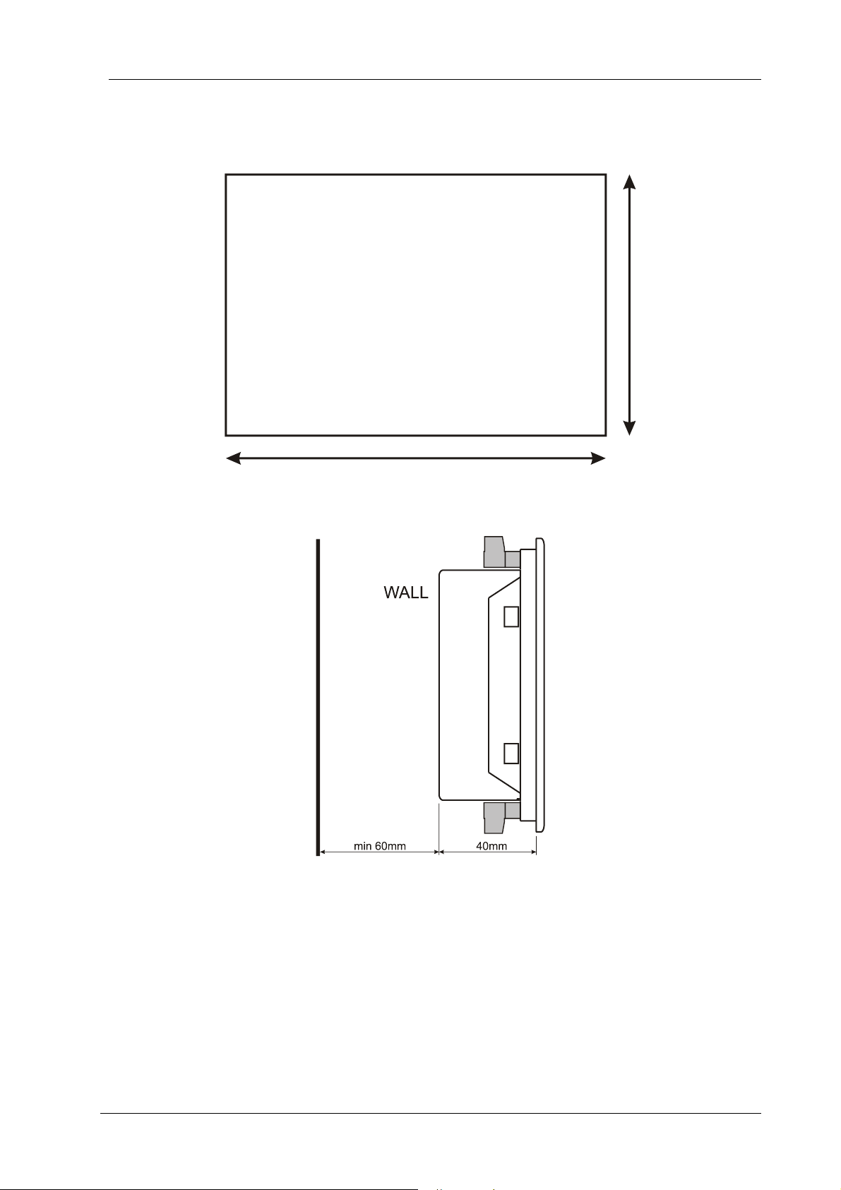
Screw type bracket
Stock Code=J10P01 (per unit)
Self Retaining type bracket
Stock Code=K16P01 (per unit)
Sealing Gasket
SPARE PARTS
ORDERING CODES
Family Code
PLUG-IN MODULE
M2: 2G-GSM Modem
M3: 3G-GSM Modem
M4: 4G-GSM Modem
W: WiFi module
E: Ethernet module
R4: RS-485 module
R2: RS-232 module
With Conformal
Coating
Variant
00: standard unit
01...99: customer
specific products
With Sealing
Gasket

D-300 MK2 User Manual Firmware V-6.3
L052D01-EN - 5 -
▪ Electrical equipment should be installed only by qualified
specialist. No responsibility is assured by the manufacturer or
any of its subsidiaries for any consequences resulting from the
non-compliance to these instructions.
▪ Check the unit for cracks and damages due to transportation. Do
not install damaged equipment.
▪ Do not open the unit. There are no serviceable parts inside.
▪ Fuses must be connected to the power supply and phase voltage
inputs, in close proximity of the unit.
▪ Fuses must be of fast type (FF) with a maximum rating of 6A.
▪ Disconnect all power before working on equipment.
▪ When the unit is connected to the network do not touch
terminals.
▪ Short circuit terminals of unused current transformers.
▪ Any electrical parameter applied to the device must be in the
range specified in the user manual. Although the unit is designed
with a wide safety margin, over-range parameters may reduce
lifetime, alter operational precision or even damage the unit.
▪ Do not try to clean the device with solvent or the like. Only clean
with a dump cloth.
▪ Verify correct terminal connections before applying power.
▪ Only for front panel mounting.
SAFETY NOTICE
Failure to follow below instructions
Current Transformers must be used for current measurement.
No direct connection allowed.

D-300 MK2 User Manual Firmware V-6.3
L052D01-EN - 6 -
1. INSTALLATION INSTRUCTIONS
2. MOUNTING
2.1 DIMENSIONS
2.2 SEALING, GASKET
2.3 ELECTRICAL INSTALLATION
3. TERMINAL DESCRIPTIONS
3.1. BATTERY VOLTAGE INPUT
3.2. AC VOLTAGE INPUTS
3.3. AC CURRENT INPUTS
3.4. DIGITAL INPUTS
3.5. ANALOG SENDER INPUTS AND SENDER GROUND
3.6. CHARGE INPUT TERMINAL
3.7. MAGNETIC PICKUP INPUT
3.8. MAINS CONTACTOR OUTPUT
3.9. GENERATOR CONTACTOR OUTPUT
3.10. DIGITAL OUTPUTS
3.11. INPUT/OUTPUT EXTENSION
3.12. RS-485 PORT (PLUG-IN MODULE)
3.13. J1939-CANBUS PORT
3.14. USB DEVICE PORT
3.15. GSM MODEM (PLUG-IN MODULE)
3.16. ETHERNET PORT (PLUG-IN MODULE)
3.17. WI-FI (PLUG-IN MODULE)
4. TOPOLOGIES
4.1. SELECTING THE TOPOLOGY
4.2. 3 PHASE, 4 WIRE, STAR
4.3. 3 PHASE, 3 WIRE, DELTA
4.4. 3 PHASE, 4 WIRE, DELTA
4.5. 3 PHASE, 3 WIRE, DELTA, 2 CT (L1-L2)
4.6. 3 PHASE, 3 WIRE, DELTA, 2 CT (L1-L3)
4.7. 2 PHASE, 3 WIRE, DELTA, 2 CTs (L1-L2)
4.8. 2 PHASE, 3 WIRE, DELTA, 2 CTs (L1-L3)
4.9. 1 PHASE, 2 WIRE
TABLE OF CONTENTS

D-300 MK2 User Manual Firmware V-6.3
L052D01-EN - 7 -
5. FUNCTIONALITIES
5.1. CT LOCATION SELECTION
5.2. AMF FUNCTIONALITY
5.3. ATS FUNCTIONALITY
5.4. REMOTE START FUNCTIONALITY
5.5. ENGINE CONTROLLER FUNCTIONALITY
5.6. -
5.7. 400HZ OPERATION
6. CONNECTION DIAGRAMS
6.1. AMF FUNCTIONALITY, CTs AT LOAD SIDE
6.2. AMF FUNCTIONALITY, CTs AT ALTERNATOR SIDE
6.3. ATS FUNCTIONALITY
6.4. REMOTE START FUNCTIONALITY
6.5. ENGINE CONTROL FUNCTIONALITY
6.6. -
7. TERMINAL DESCRIPTION
8. TECHNICAL SPECIFICATIONS
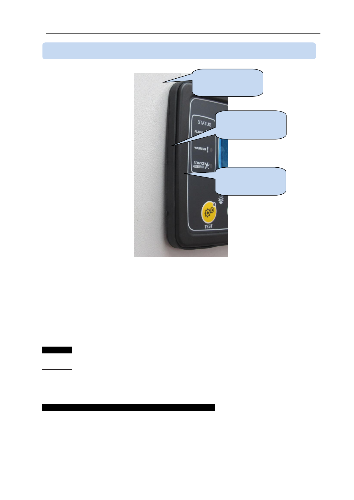
9. DESCRIPTION OF CONTROLS
9.1. FRONT PANEL FUNCTIONALITY
9.2. PUSHBUTTON FUNCTIONS
9.3. DISPLAY SCREEN ORGANIZATION
9.4. AUTOMATIC DISPLAY SCROLL
9.5. MEASURED PARAMETERS
9.6. LED LAMPS
10. WAVEFORM DISPLAY & HARMONIC ANALYSIS
11. DISPLAYING EVENT LOGS
12. STATISTICAL COUNTERS
12.1. FUEL FILLING COUNTER
12.2. FUEL CONSUMPTION MONITORING
13. OPERATION OF THE UNIT
13.1. QUICK START GUIDE
13.2. STOP MODE
13.3. AUTO MODE
13.4. RUN MODE, MANUAL CONTROL
13.5. TEST MODE

D-300 MK2 User Manual Firmware V-6.3
L052D01-EN - 8 -
14. PROTECTIONS AND ALARMS
14.1. DISABLING ALL PROTECTIONS
14.2. SERVICE REQUEST ALARM
14.3. SHUTDOWN ALARMS
14.4. LOADDUMP ALARMS
14.5. WARNINGS
14.6. NON-VISUAL WARNINGS
15. PROGRAMMING
15.1. RESETTING TO FACTORY DEFAULTS
15.2. ENTERING THE PROGRAMMING MODE
15.3. NAVIGATING BETWEEN MENUS
15.4. MODIFYING PARAMETER VALUE
15.5. PROGRAMMING MODE EXIT
16. PROGRAM PARAMETER LIST
16.1. CONTROLLER CONFIGURATION GROUP
16.2. ELECTRICAL PARAMETERS GROUP
16.3. ENGINE PARAMETERS GROUP
16.4. ADJUST DATE AND TIME
16.5. WEEKLY OPERATION SCHEDULE
16.6. EXERCISER SCHEDULE
16.7. SENDER CONFIGURATION
16.8. DIGITAL INPUT CONFIGURATION
16.9. OUTPUT CONFIGURATION
16.10. SITE ID STRING
16.11. ENGINE SERIAL NUMBER
16.12. MODEM1-2/SMS1-2-3-4 TELEPHONE NUMBERS
16.13. GSM MODEM PARAMETERS
16.14. TCP/IP PARAMETERS
16.15. Wi-Fi PARAMETERS
17. ETHERNET CONFIGURATION
18. Wi-Fi CONFIGURATION
19. GSM CONFIGURATION
20. CRANK CUTTING
21. OVERCURRENT PROTECTION (IDMT)
22. MOTORIZED CIRCUIT BREAKER CONTROL
23. J1939 CANBUS ENGINE SUPPORT
24. SMS COMMANDS

D-300 MK2 User Manual Firmware V-6.3
L052D01-EN - 9 -
25. SOFTWARE FEATURES
25.1. LOAD SHEDDING / DUMMY LOAD
25.2. LOAD ADD / SUBSTRACT
25.3. FIVE STEP LOAD MANAGEMENT
25.4. REMOTE START OPERATION
25.5. DISABLE AUTO START, SIMULATE MAINS
25.6. BATTERY CHARGING OPERATION, DELAYED SIMULATE MAINS
25.7. DUAL GENSET MUTUAL STANDBY OPERATION
25.8. MULTIPLE VOLTAGE AND FREQUENCY
25.9. SINGLE PHASE OPERATION
25.10. EXTERNAL CONTROL OF THE UNIT
25.11. AUTOMATIC EXERCISER
25.12. WEEKLY OPERATION SCHEDULER
25.13. ENGINE HEATING OPERATION
25.14. ENGİNE IDLE SPEED OPERATİON
25.15. ENGINE BLOCK HEATER
25.16. FUEL PUMP CONTROL
25.17. GAS ENGINE FUEL SOLENOID CONTROL
25.18. PRE-TRANSFER SIGNAL
25.19. CHARGING THE ENGINE BATTERY
25.20. EXTERNALLY CONTROLLED DIGITAL OUTPUTS
25.21. COMBAT MODE
25.22. RESETTING THE CONTROLLER
25.23. -
25.24. ZERO POWER AT REST
26. MODBUS COMMUNICATIONS
27.1. PARAMETERS REQUIRED FOR RS-485 MODBUS OPERATION
27.2. DATA FORMATS
27. DECLARATION OF CONFORMITY
28. MAINTENANCE
29. DISPOSAL OF THE UNIT
30. ROHS COMPLIANCE
31. TROUBLESHOOTING GUIDE
D-300 MK2 User Manual Firmware V-6.3
L052D01-EN - 10 -
Before installation:
▪ Read the user manual carefully, determine the correct connection diagram.
▪ Remove all connectors and mounting brackets from the unit, then pass the unit through the
mounting opening.
▪ Put mounting brackets and tighten. Do not tighten too much, this can brake the enclosure.
▪ Make electrical connections with plugs removed from sockets, then place plugs to their sockets.
▪ Be sure that adequate cooling is provided.
▪ Be sure that the temperature of the environment will not exceed the maximum operating
temperature in any case.
Below conditions may damage the device:
▪ Incorrect connections.
▪ Incorrect power supply voltage.
▪ Voltage at measuring terminals beyond specified range.
▪ Voltage applied to digital inputs over specified range.
▪ Current at measuring terminals beyond specified range.
▪ Overload or short circuit at relay outputs
▪ Connecting or removing data terminals when the unit is powered-up.
▪ High voltage applied to communication ports.
▪ Ground potential differences at non-isolated communication ports.
▪ Excessive vibration, direct installation on vibrating parts.
Below conditions may cause abnormal operation:
▪ Power supply voltage below minimum acceptable level.
▪ Power supply frequency out of specified limits
▪ Phase order of voltage inputs not correct.
▪ Current transformers not matching related phases.
▪ Current transformer polarity incorrect.
▪ Missing grounding.
Current Transformers must be used for current
measurement.
No direct connection allowed.
1. INSTALLATION INSTRUCTIONS

D-300 MK2 User Manual Firmware V-6.3
L052D01-EN - 11 -
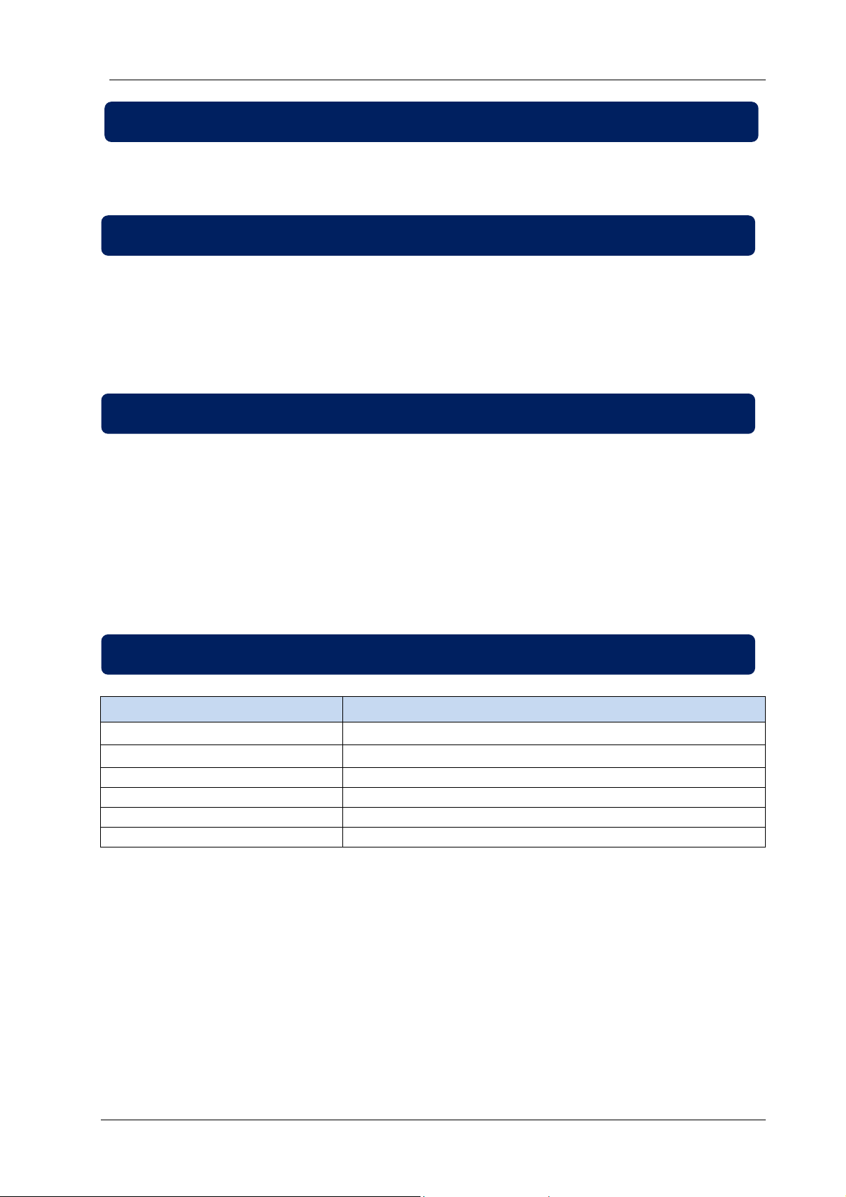
Dimensions: 180x140x46mm (7”x5.5”x1.9”)
Panel Cutout: 151x111mm minimum (6.0”x4.4”)
Weight: 300g (0.7 lb)
Mount the unit on a flat, vertical surface. Before mounting, remove the mounting brackets and connectors
from the unit, then pass the unit through the mounting opening.
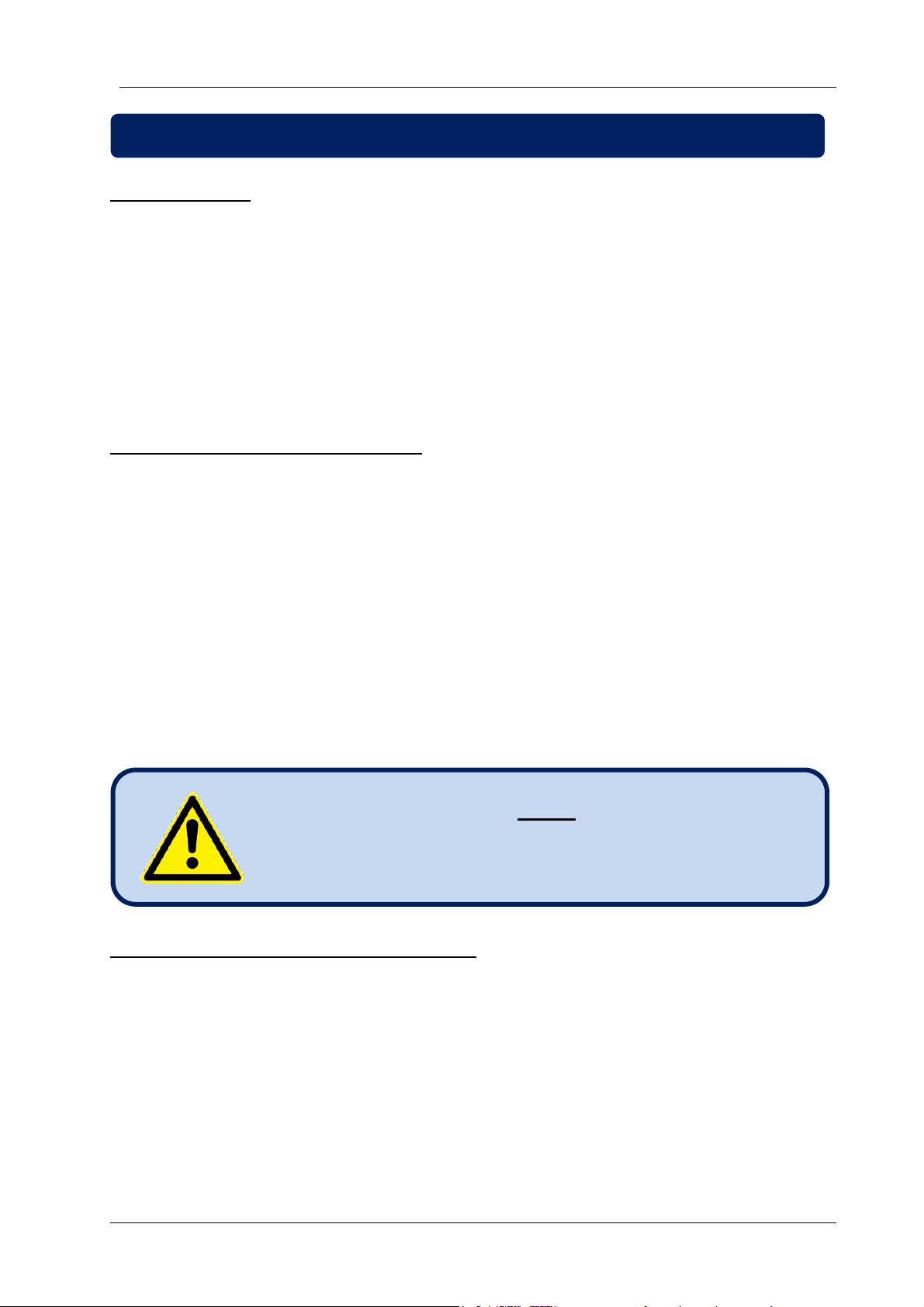
The unit is designed for panel mounting. The user
should not be able to access parts of the unit other
than the front panel.
2.1. DIMENSIONS
2. MOUNTING
D-300 MK2 User Manual Firmware V-6.3
L052D01-EN - 12 -
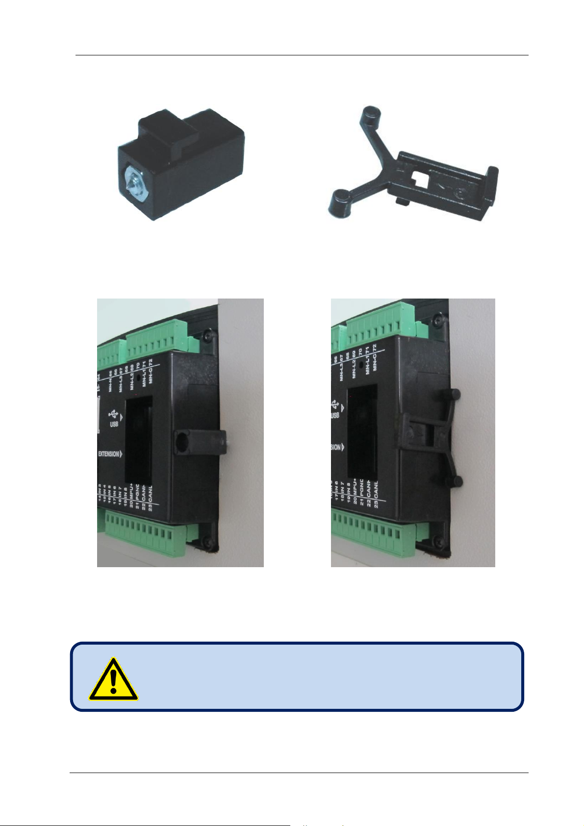
Place and tighten mounting brackets.
111mm
151mm
Panel Cutout
Required Panel Depth
D-300 MK2 User Manual Firmware V-6.3
L052D01-EN - 13 -
Two different types of brackets are provided:
Screw type bracket
Self retaining type bracket
Installation of screw type bracket
Installation of self retaining type bracket
Do not tighten too much, this may break the unit.
D-300 MK2 User Manual Firmware V-6.3
L052D01-EN - 14 -
The rubber gasket provides a watertight means of mounting the module to the genset panel. Together
with the gasket, IEC 60529-IP65 protection can be reached from the front panel. A short definition of IP
protection levels is given below.
1st Digit Description of Protection Level
0 Not protected
1 Protected against solid foreign objects of 50 mm diameter and greater
2 Protected against solid foreign objects of 12,5 mm diameter and greater
3 Protected against solid foreign objects of 2,5 mm diameter and greater
4 Protected against solid foreign objects of 1,0 mm diameter and greater
5 Protected from the amount of dust that would interfere with normal operation
6 Dust tight
2nd Digit Description of Protection Level
0 Not protected
1 Protected against vertically falling water drops
2 Protected against vertically falling water drops when enclosure is tilted up to 15 °
3 Protected against water sprayed at an angle up to 60 ° on either side of the vertical
4 Protected against water splashed against the component from any direction
5 Protected against water projected in jets from any direction
6 Protected against water projected in powerful jets from any direction
7 Protected against temporary immersion in water
8 Protected against continuous immersion in water, or as specified by the user
2.2. SEALING, GASKET
Gasket
Panel
Module

D-300 MK2 User Manual Firmware V-6.3
L052D01-EN - 15 -
Although the unit is protected against electromagnetic disturbance, excessive
disturbance can affect the operation, measurement precision and data communication
quality.
▪ ALWAYS remove plug connectors when inserting wires with a screwdriver.
▪ Fuses must be connected to the power supply and phase voltage inputs, in
close proximity of the unit.
▪ Fuses must be of fast type (FF) with a maximum rating of 6A.
▪ Use cables of appropriate temperature range.
▪ Use adequate cable section, at least 0.75mm2 (AWG18).
▪ Follow national rules for electrical installation.
▪ Current transformers must have 1A or 5A output.
▪ For current transformer inputs, use at least 1.5mm2 section (AWG15) cable.
▪ The current transformer cable length should not exceed 1.5 meters. If
longer cable is used, increase the cable section proportionally.
For the correct operation of the exerciser and
weekly schedule programs, adjust the real time
clock of the unit through programming menu.
The engine body must be grounded. Otherwise faulty
voltage and frequency measurements may occur.
Current Transformers must be used for current
measurement.
No direct connection allowed.
Do not install the unit close to high electromagnetic
noise emitting devices like contactors, high current
busbars, switchmode power supplies and the like.
2.3. ELECTRICAL INSTALLATION

D-300 MK2 User Manual Firmware V-6.3
L052D01-EN - 16 -
Supply voltage:
8 to 36VDC
Cranking dropouts:
Survives 0VDC during 100ms. The voltage before surge should be
8VDC minimum
Overvoltage protection:
Withstands 150VDC continuously.
Reverse voltage:
-150VDC continuous
Maximum operating
current:
500mA @ 12VDC. (All options included, digital outputs open.)
250mA @ 24VDC. (All options included, digital outputs open.)
Typical operating current:
250mA @ 12VDC. (all options passive, digital outputs open)
125mA @ 24VDC. (all options passive, digital outputs open)
Measurement range:
0 to 36VDC
Display resolution:
0.1VDC
Accuracy:
0.5% + 1 digit @ 24VDC
3.1. BATTERY VOLTAGE INPUT
3. TERMINAL DESCRIPTIONS

D-300 MK2 User Manual Firmware V-6.3
L052D01-EN - 17 -
Measurement method:
True RMS
Sampling rate:
8000 Hz
Harmonic analysis:
up to 31th harmonic
Input voltage range:
14 to 300 VAC
Minimum voltage for
frequency detection:
15 VAC (Ph-N)
Supported topologies:
3 ph 4 wires star
3 ph 3 wires delta
3ph 4 wires delta
2ph 3 wires L1-L2
2ph 3 wires L1-L3
1 ph 2 wires
Measurement range:
0 to 330VAC ph-N (0 to 570VAC ph-ph)
Common mode offset:
max 100V between neutral and BAT-
Input impedance:
4.5M-ohms
Display resolution:
1VDC
Accuracy:
0.5% + 1 digit @ 230VAC ph-N (±2VAC ph-N)
0.5% + 1 digit @ 400VAC ph-ph (±3VAC ph-ph)
Frequency range:
DC to 650Hz
Frequency display
resolution:
0.1 Hz
Frequency accuracy:
0.2% + 1 digit (±0.1 Hz @ 50Hz)
3.2. AC VOLTAGE INPUTS

D-300 MK2 User Manual Firmware V-6.3
L052D01-EN - 18 -
Measurement method:
True RMS
Sampling rate:
8000 Hz
Harmonic analysis:
up to 31th harmonic
Supported topologies:
3 ph 3 CTs
3 ph 2 CTs L1-L2
3 ph 2 CTs L1-L3
2 ph 2 CTs L1-L2
2 ph 2 CTs L1-L3
1 ph 1 CT
CT secondary rating:
5A or 1A
Measurement range:
5/5 to 5000/5A minimum
Input impedance:
15 mili-ohms
Burden:
0.375W
Maximum continuous
current:
6A
Measurement range:
0.1 to 7.5A
Common mode offset:
Max 30VAC between BAT- and any CT terminal.
Display resolution:
1A
Accuracy:
0.5% + 1 digit @ 5A (± 4.5A @ 5/500A full range)
SELECTING THE CT RATING AND CABLE SECTION:
The load on a CT should be kept
minimum in order to minimize phase shift
effect of the current transformer. Phase
shift in a CT will cause erroneous power
and power factor readings, although amp
readings are correct.
Datakom advises CT rating to be selected
following this table for the best
measurement accuracy.
SELECTING THE CT ACCURACY CLASS:
The CT accuracy class should be selected in accordance with the required measurement precision. The
accuracy class of the Datakom controller is 0.5%. Thus 0.5% class CTs are advised for the best result.
3.3. AC CURRENT INPUTS

D-300 MK2 User Manual Firmware V-6.3
L052D01-EN - 19 -
CONNECTING CTs:
Be sure of connecting each CT to the related phase input with the correct polarity. Mixing CTs between
phases will cause faulty power and pf readings.
Many combinations of incorrect CTs connections are possible, so check both order of CTs and their
polarity. Reactive power measurement is affected by incorrect CTs connection in similar way as active
power measurement.
CORRECT CT CONNECTIONS
Let’s suppose that the genset is loaded with 100 kW on each phase. The load Power Factor (PF) is 1.
Measured values are as follows:
kW
kVAr
kVA
pf
Phase L1
100.0
0.0
100
1.00
Phase L2
100.0
0.0
100
1.00
Phase L3
100.0
0.0
100
1.00
Total
300.0
0.0
300
1.00
▪ Current Transformers must be used for current
measurement. No direct connection allowed.
▪ No common terminals or grounding allowed.

D-300 MK2 User Manual Firmware V-6.3
L052D01-EN - 20 -
EFFECT OF POLARITY REVERSAL
The generator is still loaded with 100 kW On each phase. The load Power Factor (PF) is 1.
PF in phase L2 will show -1,00 due to reverse CT polarity. The result is that total generator power
displayed by the controller is 100 kW.
Measured values are as follows:
kW
kVAr
kVA
pf
Phase L1
100.0
0.0
100
1.00
Phase L2
-100.0
0.0
100
-1.00
Phase L3
100.0
0.0
100
1.00
Total
100.0
0.0
300
0.33
EFFECT OF PHASE SWAPPING
The generator is still loaded with 100 kW on each phase. The load Power Factor (PF) is 1.
PF in phases L2 and L3 will show -0,50 due to phase shift between voltages and currents which is
caused by CT swapping. The result is that total generator power displayed by controller is 0 kW.
Measured values are as follows:
kW
kVAr
kVA
pf
Phase L1
100.0
0.0
100
1.00
Phase L2
-50.0
86.6
100
-0.50
Phase L3
-50.0
-86.6
100
-0.50
Total
0.0
0.0
300
0.0

D-300 MK2 User Manual Firmware V-6.3
L052D01-EN - 21 -
Type of inputs:
all configurable
Function selection:
from list
Contact type:
Normally open or normally closed (programmable)
Switching:
Battery negative or battery positive (programmable)
Structure:
47 k-ohms resistor to battery positive, 110k-ohms to battery negative.
Measurement:
Analog voltage measurement.
Open circuit voltage:
70% of battery voltage
Low level threshold:
35% of battery voltage
High level threshold:
85% of battery voltage
Maximum input voltage:
+100VDC with respect to battery negative
Minimum input voltage:
-70VDC with respect to battery negative
Noise filtering:
yes
Type of inputs:
all configurable, additional sender ground input
Function selection:
from list
Structure:
667 ohms resistor polarizing to +3.3VDC
Measurement:
Analog resistor measurement.
Open circuit voltage:
+3.3VDC
Short circuit current:
5mA
Measurement range:
0 to 5000 ohms.
Open circuit threshold:
5000 ohms.
Resolution:
1 ohms @ 300 ohms or lower
Accuracy:
2 %+1 ohm (±7 ohms @300 ohms)
Common mode voltage
range:
± 3VDC
Noise filtering:
yes
3.5. ANALOG SENDER INPUTS AND SENDER GROUND
3.4. DIGITAL INPUTS

D-300 MK2 User Manual Firmware V-6.3
L052D01-EN - 22 -
The Charge terminal is both an input and output.
When the engine is ready to run, this terminal supplies the excitation current to the charge alternator.
The excitation circuit is equivalent to a 2W lamp.
The threshold voltages for warning and shutdown alarm are adjustable through program parameter.
Structure:
• battery voltage output through 100 ohm resistor
• voltage measurement input
Output current:
100mA @12VDC
200mA @24VDC
Voltage measurement
resolution:
0.1VDC
Voltage measurement
accuracy:
2% + 0.1V (0.9V @30VDC)
Charge Fail Warning
Threshold:
adjustable
Charge Fail Shutdown
Alarm Threshold:
adjustable
Open circuit voltage:
battery positive
Overvoltage protection:
> 500VDC continuous, with respect to battery negative
Reverse voltage
protection:
-30VDC with respect to battery negative
Structure:
Differential frequency measurement input
Input impedance:
50 k-ohms
Input voltage:
0.5VAC-RMS to 50VAC-RMS
Frequency range:
10Hz to 10 kHz
Resolution:
1 rpm
Accuracy:
0.2% + 1 rpm (±3rpm @1500 rpm)
Flywheel teeth range:
1 to 500
Do not share MPU with other devices.
3.6. CHARGE INPUT TERMINAL
3.7. MAGNETIC PICKUP INPUT

D-300 MK2 User Manual Firmware V-6.3
L052D01-EN - 23 -
Structure:
Relay output, normally closed contact. One terminal is internally
connected to mains phase L1 input.
Max switching current:
16A @250VAC
Max switching voltage:
440VAC
Max switching power:
3000VA
Structure:
Relay output, normally open contact. One terminal is internally
connected to genset phase L1 input.
Max switching current:
16A @250VAC
Max switching voltage:
440VAC
Max switching power:
4000VA
Structure:
Negative pulling protected semiconductor output. One terminal is
connected to battery negative.
Function
programmable, selectable from list.
Max continuous current:
1.0 ADC
Max switching voltage:
33 VDC
Overvoltage protection:
40 VDC
Short circuit protection:
> 1.7 ADC
Reverse voltage
protection:
500 VDC
3.9. GENERATOR CONTACTOR OUTPUT
3.10. DIGITAL OUTPUTS
3.8. MAINS CONTACTOR OUTPUT

D-300 MK2 User Manual Firmware V-6.3
L052D01-EN - 24 -
The module provides resources for 32 additional digital inputs
and 32 additional digital outputs.
Digital inputs can be extended using DKG-188 Digital Input
Extension modules, each one providing 8 inputs. Digital
inputs are programmable through the main controller. The
switching characteristic is not programmable and must be
battery negative. Any function can be assigned to digital
inputs.
Digital outputs can be extended using DKG-186 Fet
Extension modules, each one providing 8 outputs. Digital
outputs have the same electrical characteristics as on board
outputs. They have programmable functions through the
main controller. Any function can be assigned to any output.
Input and output extension modules are connected to the
main controller in a cascade structure, in any order. The
connection cable is provided with each extension module.
3.11. INPUT/OUTPUT EXTENSION
I/O Extension
Connector

D-300 MK2 User Manual Firmware V-6.3
L052D01-EN - 25 -
Structure:
RS-485, isolated.
Connection:
3 wires (A-B-GND). Half duplex.
Baud rate:
2400-115200 bauds, selectable
Data type:
8 bit data, no parity, 1 bit stop
Termination:
External 120 ohms required
Isolation:
250VAC, 1 minute
Common mode voltage:
-0.5 VDC to +7VDC, internally clamped by transient suppressors.
Max distance:
1200m @ 9600 bauds (with 120 ohms balanced cable)
The RS-485 port features MODBUS-RTU protocol. Multiple modules (up to 128) can be paralleled on the
same RS-485 bus for data transfer to automation or building management systems.
The RS-485 port provides also a good solution for distant PC connection where RainbowPlus program
will enable programming, control and monitoring.
For more details about programming, control and
monitoring through RS-485 port please refer to
RainbowPlus user manual.
The Modbus register list is available at Datakom
technical support.
3.12. RS-485 PORT (PLUG-IN MODULE)
RS-485 Slot
D-300 MK2 User Manual Firmware V-6.3
L052D01-EN - 26 -
Structure:
CANBUS, non isolated.
Connection:
3 wires (CANH-CANL-GND).
Data rate:
250 kbps
Termination:
Internal 120 ohms provided
Common mode voltage:
-0.5 VDC to +15 VDC, internally clamped by transient suppressors.
Max distance:
200m with 120 ohm balanced cable
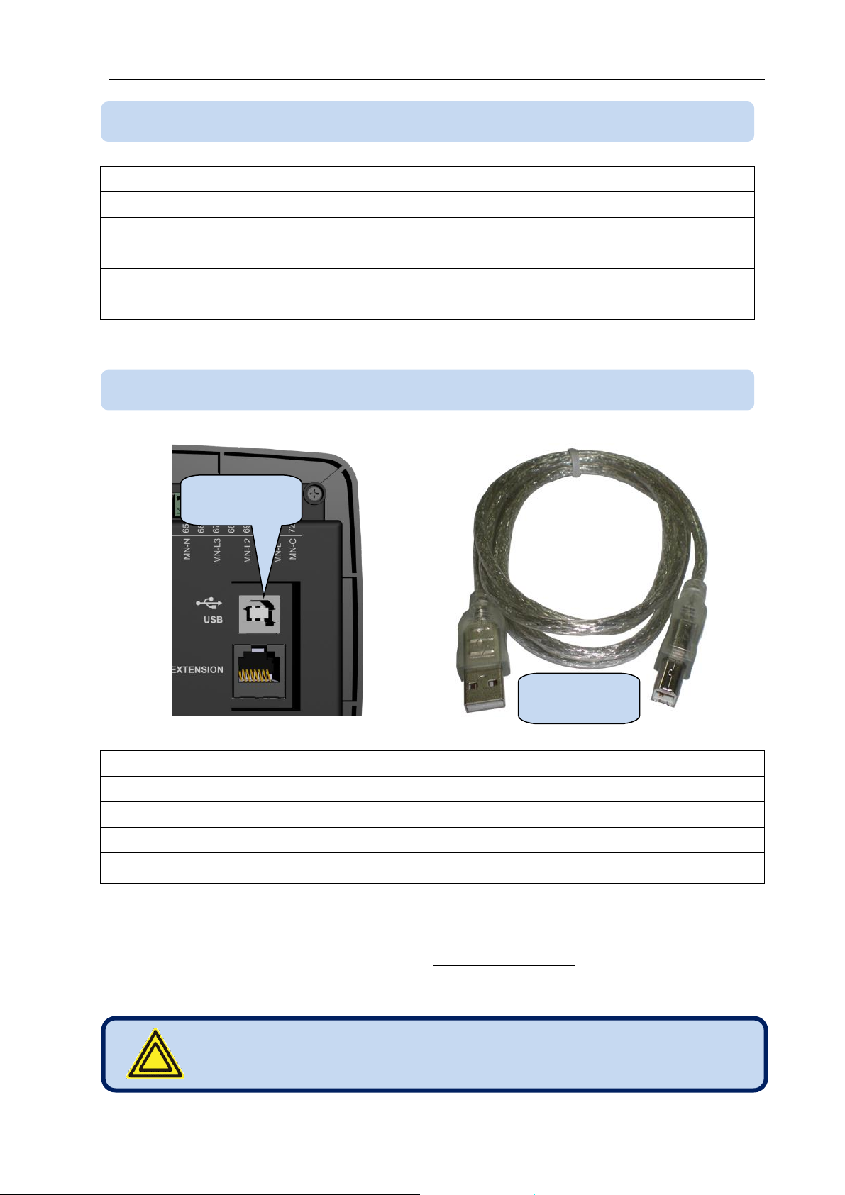
Description:
USB 2.0, not isolated, HID mode
Data rate:
Full Speed 1.5/12 Mbits/s, auto detecting
Connector:
USB-B (printer connector)
Cable length:
Max 6m
Functionality:
Modbus, FAT32 for firmware upgrade (boot loader mode only)
The USB-Device port is designed to connect the module to a PC. Using the RainbowPlus software,
programming, control of the genset and monitoring of measured parameters are achieved.
The RainbowPlus software can be downloaded from www.datakom.com.tr website.
The connector on the module is of USB-B type. Thus A to B type USB cable should be used. This is the
same cable used for USB printers.
The battery voltage must be connected.
3.14. USB DEVICE PORT
3.13. J1939-CANBUS PORT
USB A to B
Cable
USB Device
Connector

D-300 MK2 User Manual Firmware V-6.3
L052D01-EN - 27 -
The optional GSM modem offers the advantage of being internally powered and is fully compatible with
the unit. It does not require any special setup.
The 1800/1900 MHz magnetic antenna together with its 2 meter cable is supplied with the internal
modem option. The antenna is intended to be placed outside of the genset panel for the best signal
reception.
The module requires a GPRS enabled SIM card for full functionality. Voice-only type SIM cards will
usually not function properly.
Please refer to GSM Modem Configuration Guide for more details.
LOCATION DETERMINATION VIA GSM
The unit determines automatically the geographical position through the GSM network. No settings are
necessary for this.
This feature is especially useful for the remote monitoring where the controller will appear automatically at
its geo-position or for mobile gensets.
Although the controller supports also GPS location determination for more precise positioning, the GSM
based location is free of charge, available everywhere, even where GPS signal is not available.
The location precision will depend of the GSM
system. In highly populated areas, the precision is
good (a few hundred meters), but rural areas may
lead to errors of a many kilometers.
3.15. GSM MODEM (PLUG-IN MODULE)
GSM Modem Slot
D-300 MK2 User Manual Firmware V-6.3
L052D01-EN - 28 -
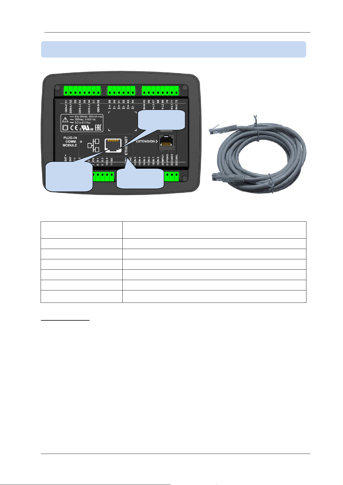
STANDARD ETHERNET CABLE
Description:
IEEE802.3 compliant, 100 Base-TX RJ45 ethernet port with
indicating leds
Data rate:
100 Mbps, auto detecting
Connector:
RJ45
Cable type:
CAT5 or CAT6
Isolation:
1500 VAC, 1 minute
Max distance:
100m with CAT5 or CAT6 cable
Functionality:
Web Client, E-mail, Modbus TCP_IP
LED FUNCTIONS:
GREEN: This led turns on when the ethernet link is established (connector inserted)
YELLOW: This led blinks when data transfer occurs inwards or outwards. Periodic blinking will witness
data flow.
3.16. ETHERNET PORT (PLUG-IN MODULE)
Ethernet
Slot
Link
Established
led
Data Flow
led
D-300 MK2 User Manual Firmware V-6.3
L052D01-EN - 29 -
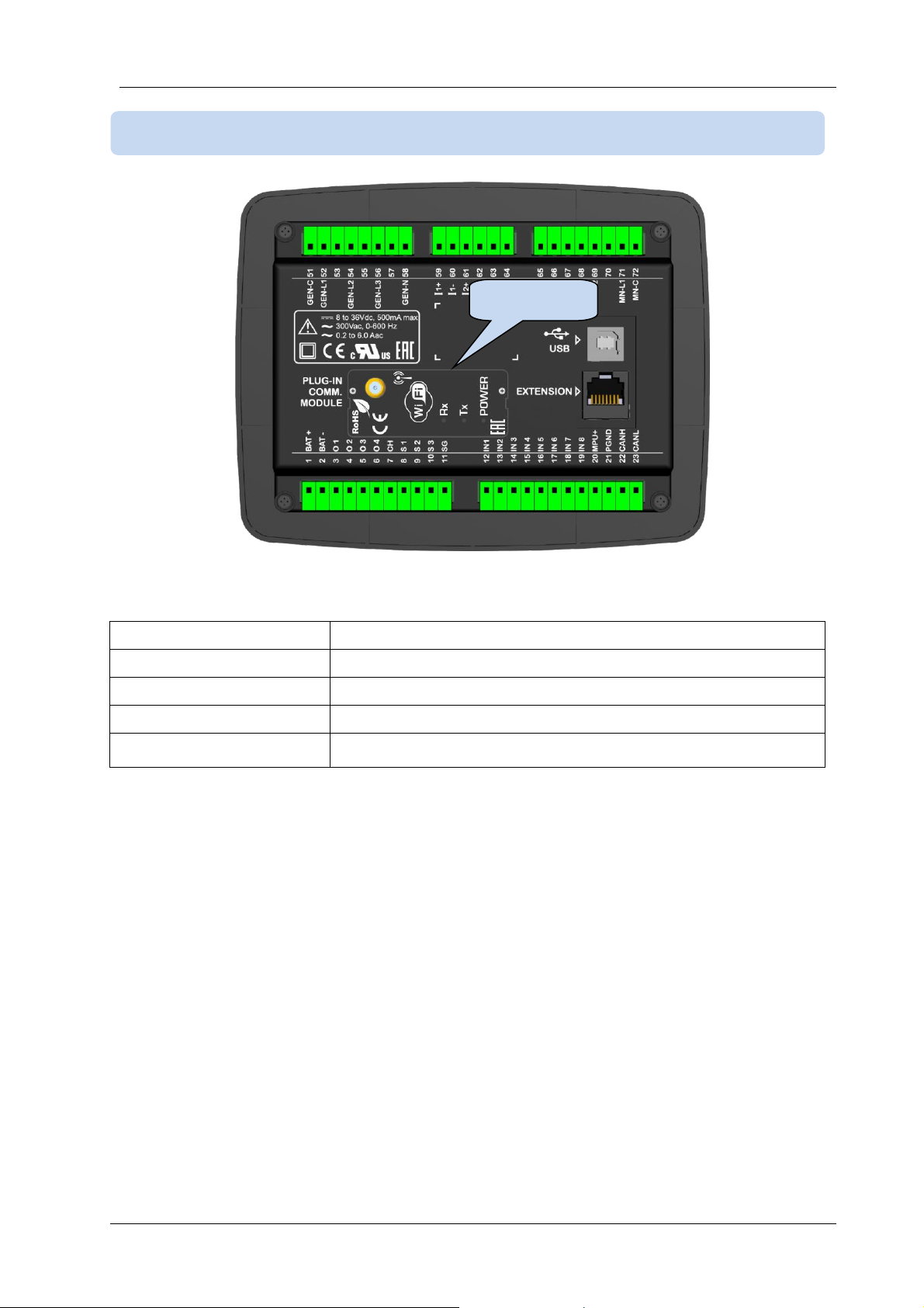
Wi-Fi protocols:
802.11 b/g/n
Frequency range:
2.4 GHz ~ 2.5 GHz (2400M ~ 2483.5M)
Network Protocols:
IPv4, TCP/UDP
Security:
WPA/WPA2
Functionality:
Web Client, E-mail, Modbus TCP_IP
3.17. Wi-Fi (PLUG-IN MODULE)
Wi-Fi Slot
D-300 MK2 User Manual Firmware V-6.3
L052D01-EN - 30 -
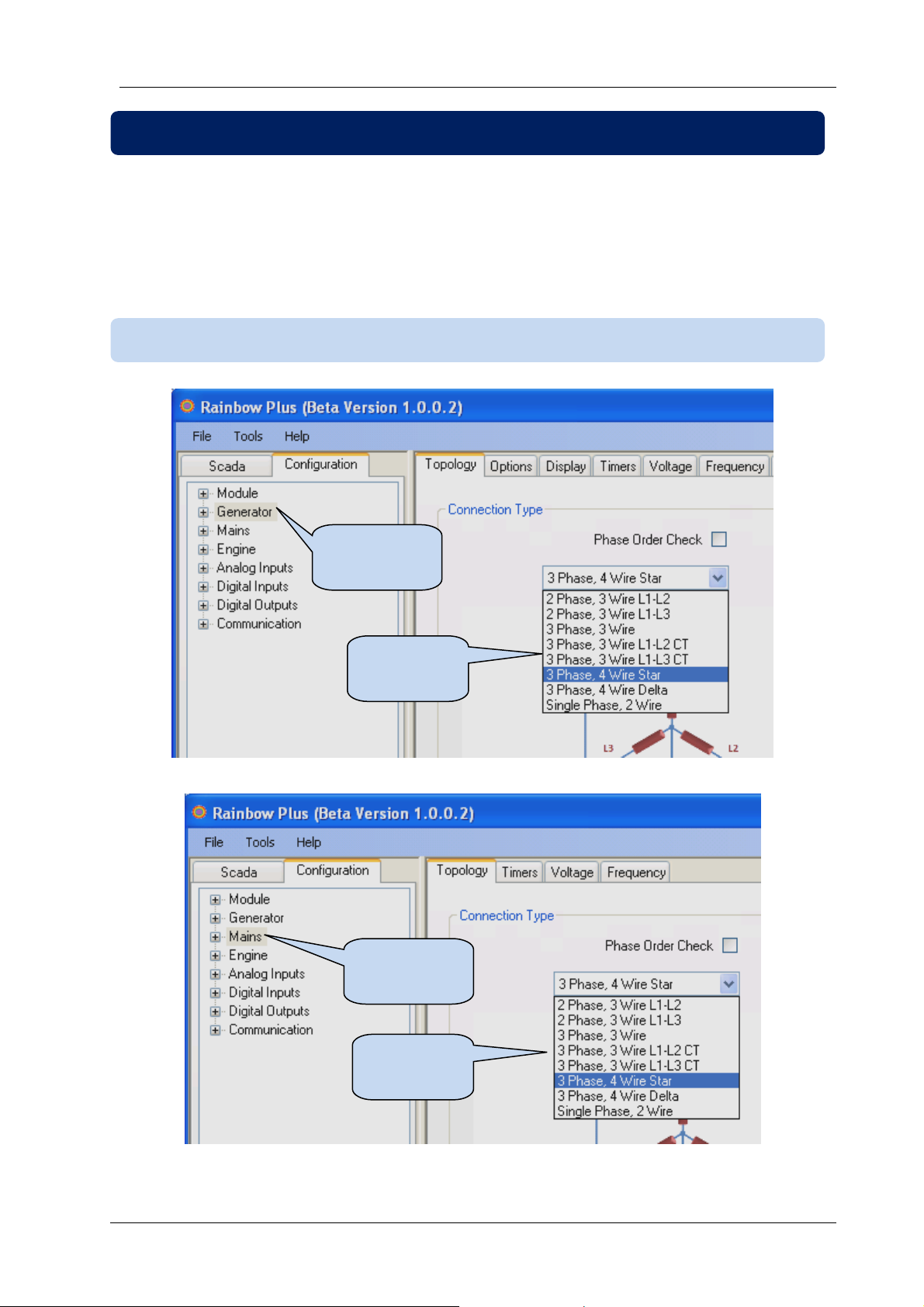
Various topologies are selectable through program parameter.
The topology is independently selectable for both genset and mains sections.
In following drawings the connections are shown for the alternator. Current transformers are supposed
connected to the alternator side.
Similar topologies re available for the mains side as well.
4.1. SELECTING THE TOPOLOGY
4. TOPOLOGIES
Generator
Parameters
Topology
Selection
Topology
Selection
Mains
Parameters
 Loading...