

DataKinetics DSC110, DSC210 User Manual

DataKinetics DSC110 / DSC210 User Manual Issue 12
Pag
e 1
DSC110 / DSC210
SIGNALLING CONVERTER
USER MANUAL

DataKinetics DSC110 / DSC210 User Manual Issue 12
Pag
e 2
IMPORTANT INFORMATION
The information in this manual is supplied without warranty as to its accuracy.
DataKinetics is not responsible or liable for any loss or damage of whatever kind
arising from the use of the converter and its documentation.
WARNINGS
For safety the ground connection should always be made.
The CPU card is fitted with a Lithium Battery that contains toxic substances. This battery is
NOT rechargeable.
CAUTION
Danger of explosion if battery is incorrectly replaced. User should not replace battery, the
card must be returned to the supplier for rework.
This equipment contains Electrostatic Sensitive Devices. (ESDs) which may be permanently
damaged if incorrectly handled. If modules are removed from the chassis they must be
handled in accordance with the EN100-015 Part 1 General Requirements.
For warnings in German see Appendix.
APPLICABILITY
This manual is applicable to DSC110 and DSC210 units with software V5.08 and later installed.
COPYRIGHT
¤1997-2001 DataKinetics Ltd. All rights reserved. No part of this document may be reproduced,
stored in a retrieval system or transmitted in any form or by any means without the prior written
permission of DataKinetics Ltd.

DataKinetics DSC110 / DSC210 User Manual Issue 12
Pag
e 3
Revision History
ISSUE DATE CHANGES
1 14-May-97
Added ANSI ISUP Functionality.
Added C7 Routing Functionality.
Added C7 Link set change Command.
Minor changes to the prerequisites, values, and parameters.
2 26-Aug-97
Digit analysis functionality added to allow route selection depending
on called party number.
Default routes added to points of origin to simplify configuration.
Further hunting algorithms added to allow sharing of load between
groups.
Allowed inhibiting of C7 links for temporary deactivation.
Enforced circular routing for circuit map hunting to avoid user
providing inconsistent data.
Allows telnet for remote login to MML session.
3 26-Sep-97
Allows timers to be configured for signalling systems.
Added NUP signalling system.
Allows NI to be changed for a linkset and DPC for a C7 route.
New hunt type added to allow test calls to particular circuits.
4 24-Nov-97
Traffic measurements commands for routes and circuit groups
added (MSCGP & MSORP).
Description of new commands for Remote Data Centre option
added. This option supports transfer of Billing Records, Call Failure
Records and Periodic Traffic Measurements to be transferred over
Ethernet to a Remote Data Centre.
Allows the specification of multiple Q931 circuit groups on a single
Q931 link.
5 09-Mar-98
Introduces support for calling party number authorisation tables
where the calling party number is required to be authorised before
the call is allowed to proceed.
Allows the default configuration to be selected when restarting
system.
Allows billing records to be saved to hard disk.
Increases the number of calling a called party number prefix digits
that can be added.
Support for transmission of alarms to remote data added.
New Zealand ISUP added.
When RTHSP is entered without parameters then hunt sequences
for all routes are printed.
The TUP signalling system is now supported.
6 22-May-98
Configuration of concurrent ITU and ANSI operation introduced.
Allows configuration of multiple OGRs in circuit mapping mode.
Partner Maintenance blocking is supported.
Inhibiting of single circuits is allowed.
T1 Boards can now be configured.
New circuit group parameters (L1, OHEC, INT) are added to
enhance the configuration of signalling parameters.
A new outgoing route parameter (CGMD) added to enhance the
configuration of signalling parameters.
Outgoing routes and Circuit Group now print 2 pages of data.
New command STCGP added to provide status on a per group
basis.
Configuration to allow the converter to act as a DUAL added.

DataKinetics DSC110 / DSC210 User Manual Issue 12
Pag
e 4
7 02-Jul-98
Semi-permanent cross connection functionality added using new
commands: CNXCI, CNXCE and CNXCP.
Monitoring of signalling links added using new MML commands:
CNMOI, CNMOE and CNMOP.
Preventive Cyclic Retransmission (PCR) method of error correction
added on a per-link basis for C7signalling links.
8 18-Dec-98
PCM configuration enhanced by addition of new parameters LC
(Line Code) and FF (Frame Format) and the ability to select T1.
New Circuit Group configuration parameters U2U, ISMD & IHEC
Maximum number of Points of Origin and Outgoing Routes
increased to 90.
New Outgoing Route parameter NEXT added.
RDC operation enhanced to allow individual primary and secondary
RDC’s to be configured (RDC1, RDC2) for each Continuous Record
and Periodic Report. New commands CNRDC, RDCRC, and
RDPRC.
Improved IP support allowing user configuration of sub-net mask
(SUBNET) and default router (GATEWAY).
New CGMD modes to avoid requesting a CLI if one is not present in
the initial setup message.
9 27-Aug-99
Manual now documents both Revision 1 and Revision 2 hardware
and the compact version of the converter – the DSC110.
Revision 2 hardware uses a different CPU card and Solid State
Memory card and requires different switch settings for the signalling
cards.
Monitor card now referred to as the Alarm card.
New table id parameters LSTAB and ISTAB so that local and user
service control can both access multiple tables.
Local service control function “calling party number authorisation” is
now supported on the point of origin as well as the outgoing route.
Added local service control function “calling party number insertion”
to allow the user to insert a calling party number taken randomly
from a table of calling party numbers.
Digit analysis can now analyse up to 16 digits.
Clearing cause and CPC mapping tables added.
New NUP variant supporting SIM interchange added.
Command grouping now arranged in alphabetical order.
New command STBOP displays board status.

DataKinetics DSC110 / DSC210 User Manual Issue 12
Pag
e 5
10 19-May-00
DPNSS signalling system added.
Added custom profiles to configure specific indicators for the calling
and called party number using the CPCGI, CPCGC, CPCGE,
CPCGP, CPCDI, CPCDC, CPCDE, and CPCDP commands.
Added the ability for the user to added/change a second calling party
number using the CG2PRE, CG2DL parameters.
Moved the ability to set the calling number restriction indication from
the CGMD to the calling party number profile.
Moved the ability to request a calling party number parameter from
the CGMD to the new RCG parameter.
Moved the ability to set the called number nature of address
indicator from the CDMD parameter to the called party number
profile.
Increased the number of prefix digits supported by CDPRE to 16.
Allow User to set a default CPC on a per circuit group basis.
Supports the ability to transit continuity indicators using new
parameter COT.
Allows the ability to upload from the remote data centre a
customised set of clearing cause mapping tables.
The USC, USM and USTAB parameter have been changed to be
ISC, ISM and ISTBL respectively.
Added CHG to the outgoing route to control the setting of the charge
indication in the backward direction.
Added CONV timers T12, T13 and T14 and added TANS to the
outgoing route to allow the user to control the time to answer on an
outgoing route basis.
Added optional password control of the second serial and 2 telnet
ports using the new PASSWORD parameter specified on a per
system basis.
Introduced the LSM parameter on a point of origin and outgoing
route basis to allow the user to specify the local service mode. This
parameter will be used to specify cli authorisation and insertion
instead of using the CGMD parameter. When uploading local
service control table a DTYPE of LSC will be used instead of
CLIAUTH.
Introduced number translation as part of local service control which
is activated using the TRANS parameter specified on a per system
basis.
Added transmission medium requirement mode to allow the user to
modify the values of the transmission medium requirement
parameter.

DataKinetics DSC110 / DSC210 User Manual Issue 12
Pag
e 6
11 25-May-00
Added announcements to allow the configuration of WAV format
voice announcements using the CNANI, CNANC, CNANE and
CNANP. The playing of these announcements is managed by the
CNVRI, CNVRE, CNVRP, and STVRP commands. A new CONV
timer, T15, is also provided for the management of announcements.
Added ENC to circuit group configuration to allow encapsulation of
ISUP parameters in Q.931 messages.
Japanese TTC ISUP protocol added, including support for 16 bit
point codes.
Support for the UK Calling Line Identity Blocking Indicator for UK
ISUP. The CBI indicator can be manipulated with the CGCB
parameter.
Added support for DPNSS Call Diversion.
Support for 56k operation on access side links.
New calling party number mode (CGMD) to add CGPRE prefix to
the calling party number if one is received.
System software disks and configuration data disks must be placed
in the floppy disk drive in a five second window during start-up. This
window is indicated by the three red alarm LEDs flashing off for five
seconds.
Added new HUNT mode to indicate that no hunting will occur.

DataKinetics DSC110 / DSC210 User Manual Issue 12
Pag
e 7
12 12-Oct-01
Allows the user to allocate b CIC of 0 or above to any device on the
system by supporting negative BCICs.
Added the ability to specify a default Japan Specific Carrier
information code by making user of the CG2PRE parameter.
Support for on box calling party number validation added using LSM.
Support for the North American ISDN protocol (NI2) as well as T1 on
ISDN boards.
CNUPI modified to support the ability to perform remote software
and configuration update from a remote data centre or locally from
floppy disk. CNBUI modified to back up configuration to a remote
data center.
Software update procedures to provide support for multiple
distribution binaries.
Enhance routing capabilities so the user is able to route on the
calling party number, CPC, called party number nature of address
and calling party number nature of address by allowing the
configuration of a DAMD on a Point of Origin basis.
Added secondary points of origin (SPOR) on points of origin or in
digit analysis to allow support for multi stage routing allowing the
user to analyse different selection criteria (e.g. CPC, called party
number) before selecting the outgoing route.
Allow the user to manipulate satellite indicators in initial address
messages using the SAT parameter on a per circuit group basis.
Allow the user to generate a bearer capability parameter based of a
received transmission medium requirement parameter using the
TMRM parameter on a circuit group basis.
Support new ASTYPE variants Q931-1 and Q931-2 to support
partner blocking on the Q931 side so that when hardware blocking
occurs on the SS7 side the Q931 signalling link is taken out of
service.
Allow the user to configure the maximum number (k) of I frames on
Q921 by configuring the L2K parameter on a per circuit group basis.
Support new COT mode to allow incoming continuity checks..
Configuration added to allow the user configure and generate an
‘early’ address complete message by using the BWM parameter on
a per outgoing route basis.
Support compatibility CRC4 operation (to allow interworking to non
CRC4).
New ASTYPEs DPNSS-2 and DPNSS-3 introduced to allow data
calls.

DataKinetics DSC110 / DSC210 User Manual Issue 12
Pag
e 8
CONTENTS
1. OVERVIEW...................................................................................................... 10
1.1 General Description ........................................................................10
1.2 Functional Summary.......................................................................11
2. SPECIFICATION – DSC110............................................................................ 15
2.1 Electrical.......................................................................................... 15
2.2 Physical........................................................................................... 16
2.3 Signalling Capability........................................................................ 16
2.4 Environmental.................................................................................16
3. SPECIFICATION – DSC210............................................................................ 17
3.1 Electrical.......................................................................................... 17
3.2 Physical........................................................................................... 18
3.3 Signalling Capability........................................................................ 18
3.4 Environmental.................................................................................18
4. TECHNICAL DESCRIPTION ........................................................................... 19
4.1 Mechanical – DSC110 ....................................................................19
4.2 Mechanical – DSC210 ....................................................................22
4.3 Electrical.......................................................................................... 25
5. INSTALLATION................................................................................................ 28
5.1 Unpacking and mounting ................................................................28
5.2 Power Wiring................................................................................... 28
5.3 Alarm Port.......................................................................................29
5.4 PCM Ports....................................................................................... 29
5.5 Serial Ports...................................................................................... 30
5.6 Ethernet Port................................................................................... 30
6. HARDWARE CONFIGURATION .....................................................................31
6.1 Signalling Card Switch Configuration.............................................. 31
6.2 Signalling Card Hardware Settings (BNC version).......................... 33
6.3 Signalling Card Hardware Settings (RJ45 version).........................34
6.4 Signalling Card E1 / T1 Selection ................................................... 35
7. OPERATION....................................................................................................36
7.1 General........................................................................................... 36
7.2 Log On/Off procedure ..................................................................... 36
7.3 Command Character Set and Syntax ............................................. 37
7.4 Command Formats ......................................................................... 38
7.5 Command Entry..............................................................................38
7.6 Dangerous Commands................................................................... 39
7.7 Changing Configuration Data.......................................................... 39
7.8 Command Responses..................................................................... 40
7.9 Updating System Software.............................................................. 41
7.10 Updating Configuration Data........................................................... 42
7.11 Parameter Definitions...................................................................... 44
7.12 Command Definitions...................................................................... 73

DataKinetics DSC110 / DSC210 User Manual Issue 12
Pag
e 9
7.13 Alarms............................................................................................. 74
7.14 Access Side Signalling.................................................................... 78
7.15 Circuit Assignment.......................................................................... 81
7.16 Configuration................................................................................... 86
7.17 Custom Profiles............................................................................. 107
7.18 SS7 Signalling............................................................................... 111
7.19 MMI...............................................................................................118
7.20 Maintenance..................................................................................120
7.21 Measurements .............................................................................. 126
7.22 Remote Data Centre..................................................................... 128
7.23 Routing.......................................................................................... 138
7.24 Status............................................................................................ 151
8. MAINTENANCE............................................................................................. 159
8.1 ESD Warning ................................................................................159
8.2 Fault Diagnosis .............................................................................159
8.3 Repair Procedure – DSC210 ........................................................ 160
9. ANNEX A: Alarm Fault Code Listing.............................................................. 164
10. ANNEX B: Clearing Cause Mappings.................................................... 170
10.1 Definitions of Internal Tokens........................................................ 170
10.2 Receive Clearing Cause Mapping Tables..................................... 173
10.3 Transmit Clearing Cause Mapping Tables.................................... 176
11. ANNEX C: Calling Party Category Mappings.........................................180
11.1 Definitions of Internal Tokens........................................................ 180
11.2 Receive Calling Party Category Mapping Tables......................... 181
11.3 Transmit Calling Party Category Mapping Tables......................... 186
12. ANNEX D: Remote Data Centre (RDC) Operation................................187
12.1 Continuous Records...................................................................... 187
12.2 Periodic Reporting......................................................................... 188
12.3 RDC File Formats ......................................................................... 189
13. ANNEX E: SAFETY...............................................................................194
13.1 AC Power Safety Warning ............................................................ 194
13.2 Lithium Battery..............................................................................194
13.3 Connector Classification ............................................................... 194
13.4 Australia and New Zealand specific..............................................195
13.5 USA and Canada specific............................................................. 195
13.6 German specific............................................................................ 195
14. ANNEX F: Command Summary............................................................ 197
15. ANNEX G: List of Part Numbers............................................................ 200
15.1 Common Equipment Spares.........................................................200
15.2 Signalling Cards............................................................................201
16. ANNEX H: Glossary of Terms ............................................................... 202

DataKinetics DSC110 / DSC210 User Manual Issue 12
Pag
e 10
1. OVERVIEW
1.1 General Description
The DSC110 and DSC210 Advanced Signalling Converters provide conversion
between network signalling protocols and access signalling protocols. On the
network side they support various Signalling System Number 7 (SS7) protocols
whilst on the access side they support various DSS1 and DPNSS protocols.
The converter is available in two chassis types, the DSC110 and DSC210. The
DSC110 supports up to 2 signalling cards and the DSC210 up to 16, providing a
migration path to larger scale systems. The operation and application interface for
both units is identical. The term DSC210 is used in the general sense to describe
both units.
1.1.1 Signalling Modes
The converter has two basic modes of operation: Signalling Only mode and Voice
and Signalling mode.
In Signalling Only mode the converter processes only the signalling channels. The
voice channels do not pass through the converter. This mode allows for the
maximum density in a single chassis by supporting (in the case of SS7 to ISDN
conversion) up to 30 access side signalling links, each channel mapping to a
corresponding channel on the SS7 side. In signalling only mode the converter
does not perform any circuit selection but instead maps access side circuits to
SS7 circuits in a fixed one to one mapping.
In Voice and Signalling mode the voice circuits also pass through the converter.
Whilst this mode does not allow for such a high density of signalling links, it does
allow the converter full control of the voice circuits. This means that the converter
can be used to select an outgoing circuit on a call by call basis. One application of
this functionality is to provide a concentration function where many access side
circuits are served on a demand basis by fewer SS7 side circuits. The converter
supports dynamic routing based on digit analysis of the called party number it also
supports retry.
It is possible to mix Signalling Only and Voice and Signalling modes at the same
time on the converter.
1.1.2 Connectivity
Signalling (and voice where applicable) can be connected to the converter using
balanced or unbalanced 2048kbit/sec (E1) connections in accordance with G.703
or 1544kbit/sec (T1) balanced connections in accordance with G.733. A fully
populated converter contains 16 signalling cards each with two E1/T1 ports giving
a total of 32 ports.
Each channel on any port can be physically connected within the converter in a
non-blocking manner to any channel on any of the 32 ports or any of the internal
signalling processors.

DataKinetics DSC110 / DSC210 User Manual Issue 12
Pag
e 11
1.1.3 User Interface
The DSC210 provides serial port(s) and telnet connections for configuration and
management. All ports provide identical functionality and operate using text based
MML (Man Machine Language) commands in accordance with CCITT
recommendations.
The serial ports allow the user to configure the converter for operation and to carry
out subsequent modifications to the configuration. They allow the user to read the
current status of the various signalling entities and to view the current active
alarms and a history of past alarm events.
The converter has alarm indicators on the front panel and alarm relays for
connection to an integrated management system.
1.1.4 Configuration and Program storage
All configuration data is stored in non-volatile memory and may optionally be
dumped to floppy disk for backup purposes or to allow a previous configuration to
be re-loaded.
All program storage is in non-volatile solid state memory. The operating software
can be updated by inserting a new software release in the floppy disk drive.
Following a software update the converter will automatically use the saved
configuration data so there is no need to re-enter the configuration parameters.
1.2 Functional Summary
1.2.1 SS7 Signalling
The converter supports up to 16 SS7 signalling links in up to 8 signalling linksets.
This allows the converter to be connected up to a maximum of 8 other signalling
points. When a linkset contains two signalling links the converter supports load
sharing and the full changeover and changeback procedures in accordance with
ITU-T Q.704.
The converter supports the Message Transfer Part (MTP) in accordance with ITU
Recommendations Q.700 .. Q.704 and Q.707 and ANSI operation in accordance
with ANSI T1.111.
If required, each signalling link in a linkset can be terminated on a separate
signalling card providing additional resilience.
The converter currently supports the following User Part variants:
ETSI ISUP Version 2
Q.767 ISUP
ANSI ISUP
NUP (UK National User Part)
UK ISUP
Australian Interconnect ISUP
New Zealand Interconnect ISUP (2 Variants)
Japanese TTC ISUP
Blue Book TUP
China TUP
SSUTR2 (French TUP)

DataKinetics DSC110 / DSC210 User Manual Issue 12
Pag
e 12
1.2.2 Access Signalling
On the access side the converter supports up to 30 access side signalling links.
Layers 2 and 3 of the access side signalling protocol are implemented on the
signalling cards. Access side call control is implemented on the central processor.
Currently the converter supports the following access signalling:
ETSI Euro ISDN (Network Side)
ETSI Euro ISDN (User Side)
North American ISDN (Network Side)
North American ISDN (User Side)
ETSI QSIG
DPNSS
1.2.3 Signalling Conversion
Signalling Conversion takes place on the central processor card. The signalling
conversion functionality receives messages from the User Part on the SS7 side
and from the ISDN/DPNSS call control module on the access side. It performs the
necessary conversion selecting a suitable outgoing route and controlling the voice
paths as necessary before sending the signalling messages to either the User
Part module or the ISDN/DPNSS call control module.
1.2.4 Configuration Model
The basic unit of configuration is a circuit group. All configured circuits (or
devices) on an access side signalling link are configured into a circuit group. On
the SS7 side groups of not more than 32 circuits (or devices) are configured into
circuit groups. It is usual (although not essential) for a circuit group to contain all
the voice circuits on an E1/T1 port.
When an incoming call arrives at the converter the decision on how to process the
call comes from the Point of Origin configuration data. Each circuit group is
assigned a single point of origin (although a single point of origin may be used by
several circuit groups). The point of origin data contains several parameters which
allow for the addition or removal of digits to both the calling and called party
numbers and also specify either a Digit Analysis Index which is used to carry out
(dynamic) routing of the call or a Default outgoing route when routing is not
required (this is always true in signalling only mode).
The digit analysis index is used to select a suitable outgoing route on which the
call should be placed. This may be one of several outgoing routes selected on the
basis of the dialled digits contained in the called party number.
The outgoing route may have an associated Next route. If present the next route
provides the ability to route to a diff erent destination if all d evices on the first
outgoing route are unavailable or an indication has been received from a
subsequent exchange indicating a problem. Since a next route is a route in its own
right a chain of routes can be formed to find the best route to a destination.
The outgoing route data contains further parameters that allow the called and
calling party numbers to be modified and a Hunt mode that controls the algorithm
used to select an outgoing circuit.
Finally the hunt sequence associated with the outgoing route is used to select a
circuit group for the outgoing call.

DataKinetics DSC110 / DSC210 User Manual Issue 12
Pag
e 13
In this manner the converter affords considerable flexibility in the way that calls
are routed from an incoming circuit to an eventual outgoing circuit allowing for the
possibility of alternative routin g in the event of network f ailure or congestion.
1.2.5 Cross Connections
The converter allows the user to set up cross connections (semi-permanent
connections) between an incoming timeslot on one PCM port and an outgoing
timeslot on any PCM port. These connections can either be simplex or duplex.
1.2.6 Monitoring
The converter allows the user to monitor both Access Side and Network Side
signalling links by dropping a copy of the signalling to a spare PCM port. This
allows for a protocol analyser to be left connected to one PCM port and gives the
user the ability to control remo tely which signalling links are monitored. Each
monitored signalling link requires two timeslots on the spare PCM port, one to
monitor the send direction and the other for the receive direction.
1.2.7 Alarm log
The converter logs any alarm events in an Alarm Log. All alarm events have a
‘fault title’ and are assigned to one of 4 classes, in decreasing order of status:
• Urgent assigned to class 3
• Prompt assigned to class 2
• Minor assigned to class 1
• Disabled assigned to class 0
The operator may change the class of any alarm event under MML command.
Urgent alarms cause the Urgent alarm relay to be activated whilst prompt alarms
cause the Prompt relay to be activated. Minor alarms just appear in the alarm log
whilst disabled alarms do not even get logged to the alarm log.
The Alarm Log has the capacity for up to 200 entries, each entry detailing the
alarm class, fault title, occurrence time, status (active or cleared), and cleared time
(if appropriate). If a new fault occurs when the log is full, the oldest entry which is
either cleared, of lower class, or equal class is overwritten, in that order of
preference.
The operator may request a display of the log at any time and may remove entries
that have cleared status.

DataKinetics DSC110 / DSC210 User Manual Issue 12
Pag
e 14
1.2.8 Remote Data Centres
The converter can optionally be equipped to support the transfer of billing records,
call failure records, alarm reports and periodic measurements over Ethernet to a
remote location – The Remote Data Cen t re (RDC).
Multiple RDC’s can be configured by specifying an IP address and a user name
and password for the converter to use to ‘logon’ to the RDC.
Data transfer to the RDC uses the File Transfer Protocol (FTP).
Billing records, call failure records and alarm reports are transferred to the RDC in
near real time with the provision to back up the billing records to hard disk in the
event of Ethernet failure. Measurement reports are made on a configurable
periodic basis.
1.2.9 Announcements
The converter can optionally play pre-recorded WAV format sound files without
the need for additional equipment. These announcements (ANNC) are loaded
onto the converter from a Remote Data Centre.
In order to play announcements the converter requires Voice Resources (VRS).
Voice resources can be configured on any signalling card s not used to process
signalling. Announcements can then be routed to and played on a per Outgoing
Route basis.

DataKinetics DSC110 / DSC210 User Manual Issue 12
Pag
e 15
2. SPECIFICATION – DSC110
2.1 Electrical
2.1.1 Power supply (DC Version)
Voltage: 46V to 56V DC (nominal 48V)
Power: 50W fully equipped
Current: 4 Amps maximum
2.1.2 Power Supply (AC Version)
Voltage Selectable:
100V-120V AC (nominal 110V)
200V-240V AC (nominal 220V)
Frequency 50/60Hz
Power 50W (fully equipped)
2.1.3 PCM interface
Data rate: 2048kbit/s
Connector: 75 ohm BNC (unbalanced version)
120 ohm RJ45 (balanced version)
Pulse shape: CCITT G.703
Framing: CCITT G.732
2.1.4 Serial Port
Connector: 9-pin D-type male.
Flow control: XON/XOFF.
Data bits: 7 or 8 user configurable.
Parity: Odd, Even or None, user configurable.
Stop Bits: 1 or 2, user configurable
Baud rate: 300, 600, 1200, 2400, 4800, 9600 or
19200 bits/s, user configurable.
2.1.5 Alarm Outputs
Type: Two relays which under normal (non-
alarm) conditions are energised. Upon
detection of an alarm condition or loss
of power the relay changes to the de-
energised state.
Designation: Urgent and Prompt

DataKinetics DSC110 / DSC210 User Manual Issue 12
Pag
e 16
Contacts: Single, break before make changeover,
voltage free
Contact
rating:
60V DC 0.5 Amps
Connector: 15-way D-type socket
2.1.6 Visual Indicators
Power: Green LED on front panel indicating power on.
Alarms: 3 red LEDs on front panel indicating Signalling,
PCM and System alarms.
Disk Drive: LED in disk drive housing indicating floppy disk
access in progress.
2.1.7 Ethernet Interface
Connector: BNC / RJ45 (autodetect)
Data Rate: 10Mbit/s
2.2 Physical
Height: 87mm
Depth: 430mm
Width: 432mm (at chassis)
Weight: 12kg (fully equipped)
2.3 Signalling Capability
SS7 Side: 4 signalling links and 4 linksets. Maximum of
two links in each linkset.
Access Side: Up to 4 signalling links
2.4 Environmental
Operating
temperature:
10 to 45 degrees Celsius
Storage
temperature:
-20 to 80 degrees Celsius
Humidity: 20% to 80% non-condensing
Vibration: 1.5G (5Hz to 2kHz)
Note: Operation of the floppy disk drive is excluded as
the floppy disk drive is not required for normal
operation.

DataKinetics DSC110 / DSC210 User Manual Issue 12
Pag
e 17
3. SPECIFICATION – DSC210
3.1 Electrical
3.1.1 Power supply
Voltage: 46V to 56V DC (nominal 48V)
Power: 200W fully equipped
Current: 4 Amps maximum
Fuse type: 8A HRC (located at rear of un it)
3.1.2 PCM interface
Data rate: 2048kbit/s
Connector: 75 ohm BNC (unbalanced version)
120 ohm RJ45 (balanced version)
Pulse shape: CCITT G.703
Framing: CCITT G.732
3.1.3 Serial Ports
Connector: 9-pin D-type male.
Flow control: XON/XOFF.
Data bits: 7 or 8 user configurable.
Parity: Odd, Even or None, user
configurable.
Stop Bits: 1 or 2, user configurable
Baud rate: 300, 600, 1200, 2400, 4800, 9600 or
19200 bits/s, user configurable.
3.1.4 Alarm Outputs
Type: Two relays which under normal (non-alarm)
conditions are energised. Upon detection of an
alarm condition or loss of power the relay
changes to the de-energised state.
Designation: Urgent and Prompt
Contacts: Single, break before make changeover, voltage
free
Contact
rating:
60V DC 0.5 Amps
Connector: 15-way D-type socket

DataKinetics DSC110 / DSC210 User Manual Issue 12
Pag
e 18
3.1.5 Visual Indicators
Power: Green LED on front panel indicating power on.
Alarms: 3 red LEDs on front panel indicating Signalling,
PCM and System alarms.
Disk Drive: LED in disk drive housing indicating floppy disk
access in progress.
3.1.6 Ethernet Interface
Connector: BNC / RJ45 (autodetect)
Data Rate: 10Mbit/s
3.2 Physical
Height: 177mm
Depth: 600mm
Width: 432mm (at chassis)
Weight: 26kg (fully equipped)
3.3 Signalling Capability
SS7 Side Up to 16 signalling links in 8 linksets. Maximum
of two links in each linkset.
Access Side: Up to 30 signalling links
3.4 Environmental
Operating
temperature:
10 to 45 degrees Celsius
Storage
temperature:
-20 to 80 degrees Celsius
Humidity: 20% to 80% non-condensing
Vibration: 1.5G (5Hz to 2kHz)
Note: Operation of the floppy disk drive is excluded as
the floppy disk drive is not required for normal
operation.

DataKinetics DSC110 / DSC210 User Manual Issue 12
Pag
e 19
4. TECHNICAL DESCRIPTION
4.1 Mechanical – DSC110
The DSC110 is designed for 19 inch rack mounting and is provided with slides to
allow top access for maintenance purposes. No side access is required. All cable
connections are at the rear of the equipment and are described in Section 5.
The DSC110 is intended for use with an extending cable carrier that should be
attached between the rear of the 19 inch rack and the converter. All cables should
then be attached to the carrier that extends and retracts as the converter is moved
forward and backwards on its slides.
The chassis contains 6 board positions and cards are positioned as detailed in the
following table. The board position numbers are marked along the rear panel of
the converter.
BOARD POSITION CARD
1 Alarm Card
2 Network Card
3 Central Processor Card
4 Solid State Memory Card
5 Signalling Processor CS6
6 Signalling Processor CS6
Table 4.1 DSC110 Physical Card Positions
DataKinetics DSC110 / DSC210 User Manual Issue 12
Pag
e 20
CARD CARRIER
POWER
SUPPLY
FLOPPY
DISK DRIVE
FAN
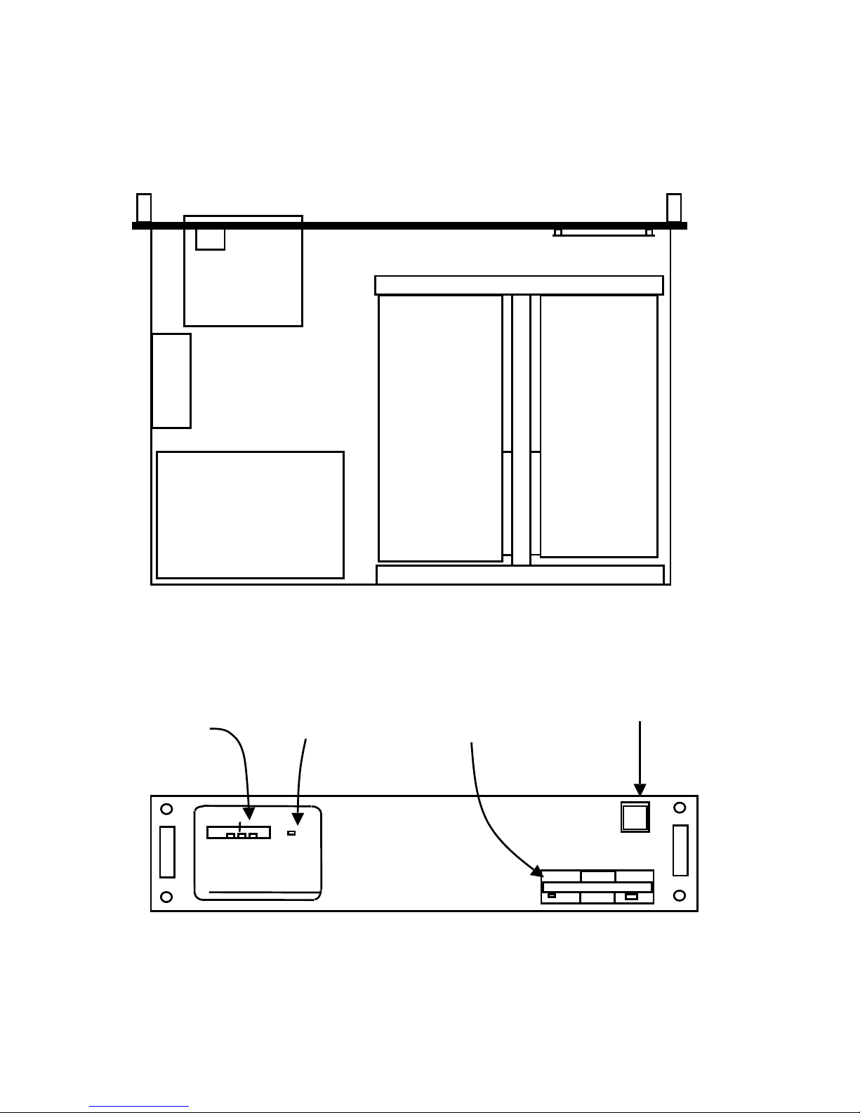
Red ‘alarm active’
indicators
Green ‘Power ON’
indicator
Floppy disk drive
Power ON switch
Figure 4.2 DSC110 front panel
Figure 4.1 - Top view of DSC110 with cover removed
DataKinetics DSC110 / DSC210 User Manual Issue 12
Pag
e 21
Serial
number
label.
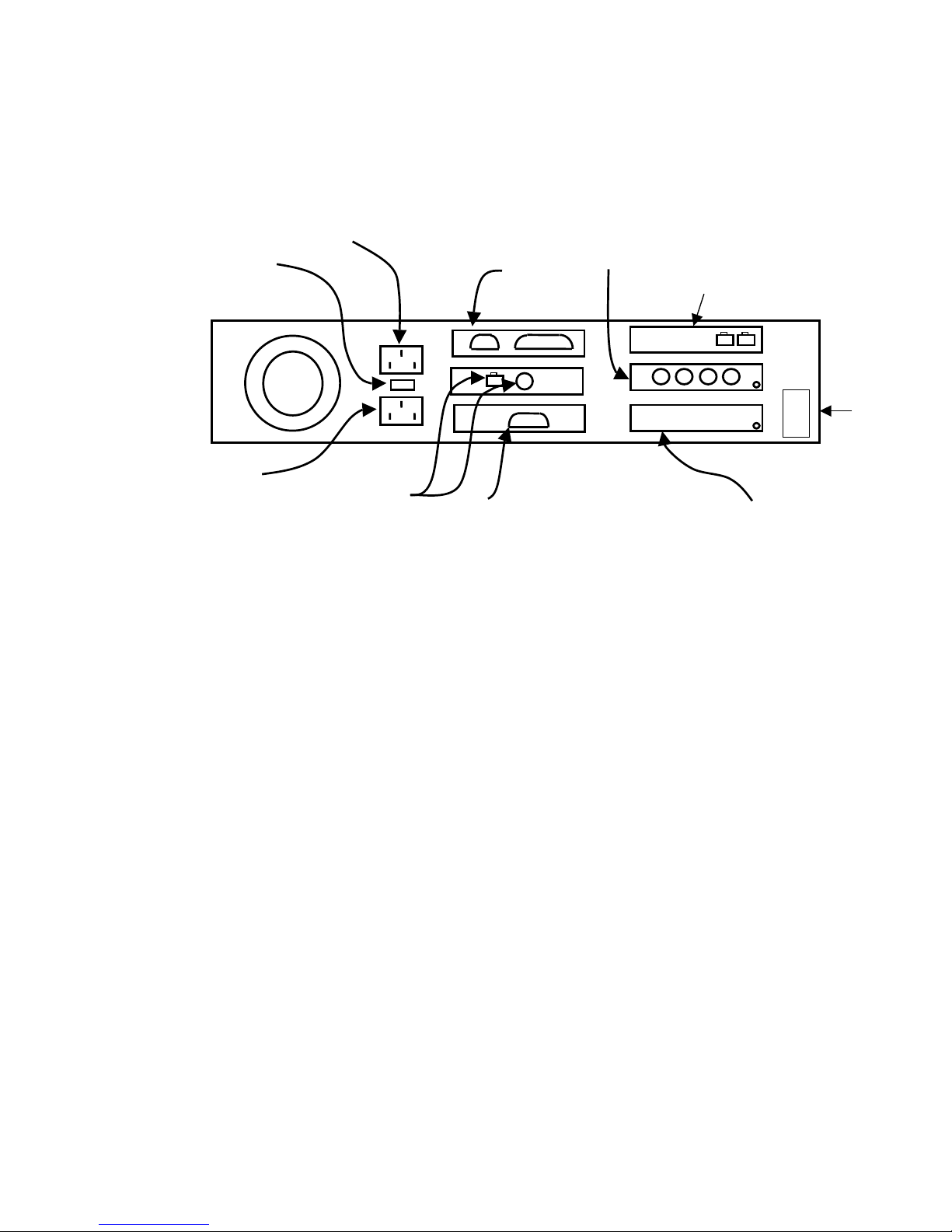
Figure 4.3 DSC110 Rear panel
Alarm Port
Ethernet
Input voltage
AC power OUT
connector
Serial Port
Solid State
Memory Card
Unbalanced 75Ω E1
signalling card
Balanced
75Ω E1
signalling
card

DataKinetics DSC110 / DSC210 User Manual Issue 12
Pag
e 22
4.2 Mechanical – DSC210
The DSC210 is designed for 19 inch rack mounting and is provided with slides to
allow top access for maintenance purposes. No side access is required. All cable
connections are at the rear of the equipment and are described in Section 5.
The DSC210 is intended for use with an extending cable carrier that should be
attached between the rear of the 19 inch rack and the converter. All cables should
then be attached to the carrier that extends and retracts as the converter is moved
forward and backwards on its slides.
The chassis contains 20 board positions and cards are positioned as detailed in
the following table. The board position numbers are marked along the front of the
board slots and on the rear panel of the converter.
BOARD POSITION CARD
1 Alarm Card
2 Network Card
3 Central Processor Card
4 Solid State Memory Card
5 Signalling Processor CS6
6 Signalling Processor CS6
7 Signalling Processor CS6
8 Signalling Processor CS6
9 Signalling Processor CS6
10 Signalling Processor CS6
11 Signalling Processor CS6
12 Signalling Processor CS6
13 Signalling Processor CS6
14 Signalling Processor CS6
15 Signalling Processor CS6
16 Signalling Processor CS6
17 Signalling Processor CS6
18 Signalling Processor CS6
19 Signalling Processor CS6
20 Signalling Processor CS6
Table 4.2 DSC210 Internal Layout
DataKinetics DSC110 / DSC210 User Manual Issue 12
Pag
e 23
.
20
19
18
17
16
15
14
13
12
11
10
9
8
7
6
5
4
3
2
1
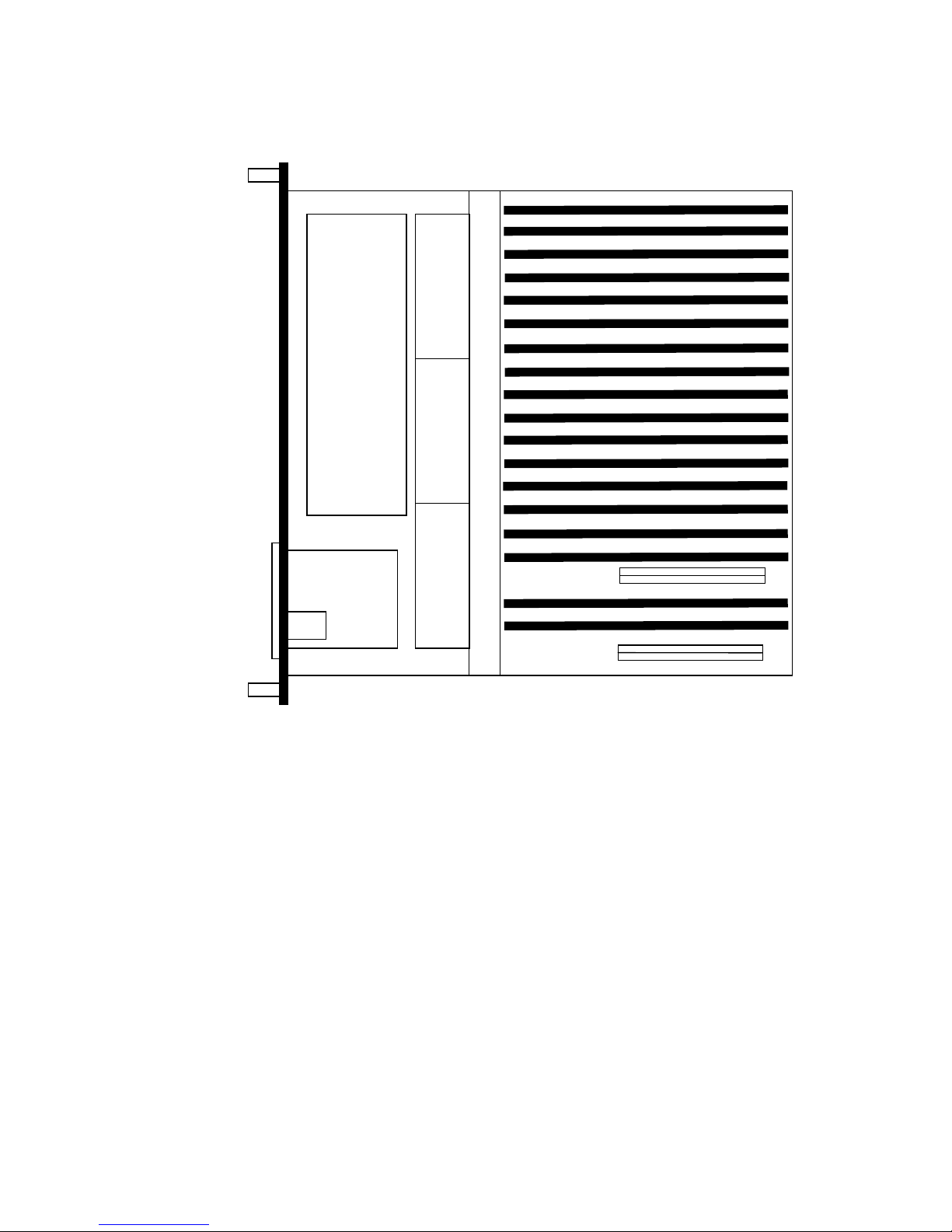
FAN 1
FAN 2
FAN 3
Power
Supply
Disk
Drive
Board Position 1
Figure 4.4 - Top view of DSC210 with cover removed
DataKinetics DSC110 / DSC210 User Manual Issue 12
Pag
e 24
1 2 3 4 5 6 17 18 19 20
Serial 1
0
1
Power
System
PCM
Signalling
Alarms
Signalling
Cards
DSC200
Series
48V
DC
ONLY
Figure 4.5 - DSC210 Front panel
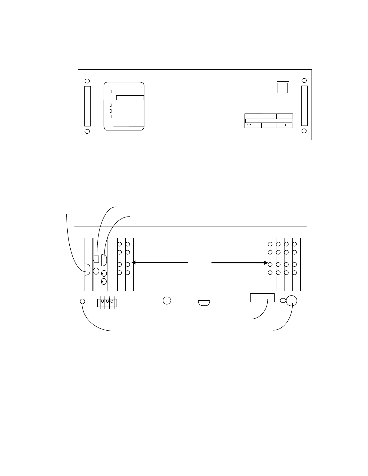
+ nc -
INPUT SUPPLY FUSE
SEE HANDBOOK
SERIAL 2
Ground Terminal
Ethernet
Serial Port 1
Cable Support Arm Securing Ring
Serial Number Label
Figure 4.6 DSC210 Rear Panel
Alarm Port
OUT 1
IN 1
OUT 2
IN 2
OUT 1
IN 1
OUT 2
IN 2
OUT 1
IN 1
OUT 2
IN 2
OUT 1
IN 1
OUT 2
IN 2
OUT 1
IN 1
OUT 2
IN 2
OUT 1
IN 1
OUT 2
IN 2
Alarm

DataKinetics DSC110 / DSC210 User Manual Issue 12
Pag
e 25
4.3 Electrical
The converter consists of a chassis and the following plug in cards:
• Central processor card
• Solid state memory card
• Signalling processor cards type CS6
• Alarm card
• Network card
4.3.1 DSC110 Chassis and Power Supply
The DSC110 is constructed from a number of cards that plug horizontally into both
sides of a card carrier fixed to the base and rear of the chassis. The chassis is
fitted with a cooling fan, hard disk, a power supply, a floppy disk drive and a front
panel display card.
The power supply converts either a nominal –48V DC supply or a switchable
110V/230V AC supply to regulated +5V, +12V, -5V and –12V DC supplies as
required by the converters electrical circuits. The input to this supply is switched
ON and OFF by the front panel switch.
The floppy disk drive is mounted at the front of the equipment, and may be used
with standard DOS format 3½ inch diskettes formatted to 1.44Mbytes. When the
disk drive is being accessed, the front panel disk drive indicator is illuminated. The
floppy disk drive is used for loading a new software release onto the converter and
for saving configuration data to disk for backup purposes.
The converter is cooled by a fan attached to the chassis also a fan that is internal
to the power supply.
4.3.2 DSC210 Chassis and Power Supply
The DSC210 chassis comprises a 20 slot passive backplane along with a power
supply module, floppy disk drive, fan power distribution and failure detection
module and a front panel display card.
The power supply converts the nominal –48V DC supply to regulated +5V, +12V, 5V and –12V DC supplies as required by the DSC210 electrical circuits. The input
to this supply is switched ON and OFF by the front panel switch.
The floppy disk drive is mounted at the front of the equipment, and may be used
with standard DOS format 3½ inch diskettes formatted to 1.44Mbytes. When the
disk drive is being accessed, the front panel disk drive indicator is illuminated. The
floppy disk drive is used for loading a new software release onto the converter and
for saving configuration data to disk for backup purposes.
The converter has three fans that run directly from the –48V DC supply. A small
circuit board situated under the fan tray provides power distribution to each of the
three fans and a fan failure detection mechanism that allows fan failure to be
reported in the alarm log.

DataKinetics DSC110 / DSC210 User Manual Issue 12
Pag
e 26
4.3.3 Central processor card
The central processor card is a single board computer that runs the main
operating software for the converter. This includes the electrical interfaces to the
two serial ports and an integral floppy disk controller.
This processor runs the configuration and management software and the
signalling conversion software. The lower levels of the protoco l software are run
on separate signalling cards.
On power up or following a system restart, the central processor card downloads
the operating code and configuration to each of the Signalling Processors cards
and configures the unit using the current configuration data.
Two different versions of the CPU card are in use. The KE18 card is used only on
Revision 1 DSC210 hardware whilst the KE30 card is a higher performance card
used on Revision 2 DSC210 hardware and the DSC110. Care should be taken to
use the correct spares.
4.3.4 Solid state memory card
The converter operating software is stored in flash memory on a solid state
memory card. The operating software comprises the operating system, the
operating program that includes the signalling converter functionality and the
operating code for each of the signalling processor cards. With the exception of
the operating system that remains fixed, all other operating software is updated in
a single operation.
Two different versions of the solid state memory card are in use. The KE17 card is
used in conjunction with KE18 CPU cards whilst KE37 is used in conjunction with
KE30 CPU cards.
4.3.5 Signalling Card Type CS6
Both network side (SS7) signalling cards and access side Q.931 signalling cards
are designated as CS6 type cards. The CS6 card provides two E1 2048kbit/s or 2
T1 1544kbit/s PCM line interfaces using either BNC connectors or RJ45
connectors.
Each signalling card contains a signalling processor that can handle up to two
signalling links or voice resources. The signalling card communicates with the
central processor using shared memory that appears in the memory map of the
central processor.
Timeslots from each PCM are routed to an inter-card PCM highway which uses a
ribbon cable connected along the top edge of all the signalling cards. This PCM
highway is used in conjunction with digital cross-connect switches on each
signalling card to allow any PCM timeslot to b e routed to any signalling resource
within the converter or to any other PCM port in the converter. The inter-card PCM
highway is used for both voice connections and signalling connections.

DataKinetics DSC110 / DSC210 User Manual Issue 12
Pag
e 27
Each PCM port in the system can be designated as a potential clock source and
assigned a relative priority. The PCM port with the highest clock priority that
currently contains a valid PCM signal is used as the synchronisation reference for
the converter. All other outputs from the converter are synchronised to this
reference source. In the event o f the active synchronisation source failin g, the
converter will select the next highest priority input source as the synchronisation
source. If no inputs contain a valid PCM signal then the converter will use a locally
generated clock reference as the synchronisation source.
Changes of PCM status are reported by the CS6 card to the central processor
card allowing alarms to be entered in the system alarm log
4.3.6 Alarm card
The Alarm card performs a supervisory function within the converter. It contains
the alarm relays and front panel LED driver circuitry to pass alarm indications to
the user and monitoring circuitry for the power supply output rails, the fan fail
detection circuitry and a temperature sensor.
Connection to the alarm relay contacts is via a 15 way D-type socket mounted at
the rear of the Alarm card. Two relays are provided designated “Prompt” and
“Urgent”. In the event of a power failure the alarms both fall back into the alarming
state.
The fan fail detector, temperature and power supply output monitor circuits are
used to detect system failures that are then reported to the central processor.
Such failures are indicated to the user by entries in the Alarm Log and the
respective front panel indicators being switched on.
4.3.7 Network card
The network card allows connection to the converter via Ethernet. This is used to
provide a telnet MML interface for configuring the converter from a remote location
and to transfer data to a Remote Data Centre.

DataKinetics DSC110 / DSC210 User Manual Issue 12
Pag
e 28
5. INSTALLATION
5.1 Unpacking and mounting
Prior to commencing installation, unpack the equipment and check for any
physical damage. In the event of damaged or missing hardware notify both the
carrier and DataKinetics immediately.
The equipment should be mounted in a suitable 19-inch rack mount cabinet, with
sufficient clearances to allow correct operation of the cooling fan(s).
For the DSC110 air is drawn into the unit through the left-hand side of the unit and
exhausted through the right hand side. For the DSC210 air is drawn into the
equipment through both sides of the chassis, and is exhausted at the top of the
rear panel.
It is recommended that the chassis be mounted at least 500mm above the floor
and not more than 1400mm high. This allows for access underneath the chassis
and avoids the need for steps to gain access to the top of the unit.
All electrical connections are made to the rear of the unit.
5.2 Power Wiring
Correct bonding of the chassis to earth is important if the converter is not to be
effected by electromagnetic interference (EMI). A separate earth connection must
be made between the earth post provided at the rear of the chassis and the
system earth point. The resistance between the chassis and the system earth
point should be no greater than 0.03 Ohms, as measured by an earth bonding
tester.
5.2.1 DSC110 Power Wiring (DC version)
Connection is by means of a two terminal screw connector block mounted at the
rear of the DSC110. The top connector is positive (+), the lower terminal negative
(-), as shown on the rear of the chassis. There is no internal connection between
the earth terminal and the power supply inputs, either pole may be connected to
earth to suit the system requirements.
The power supply is fitted with an internal fuse, which is not user replaceable.
5.2.2 DSC110 Power Wiring (AC version)
The AC power supply is dual voltage, selectable by a slider switch at the rear of
the unit. This switch is marked 230 for connection to 220-240V AC supplies, and
115 for connection to 100-120V AC supplies. This switch must be set to the
correct position before power is applied to the unit.
Connection is by means of a standard 3-pin IEC mains inlet on the rear of the
chassis. This includes a ground connection, which must be connected to a
suitable system earth. The power outlet provides a restricted nominal 230V AC or
115V AC supply for connection to ancillary equipment. The capability of this
output is labelled on the rear of the equipment. This port should not be used.
The power supply is fitted with an internal fuse, which is not user replaceable.

DataKinetics DSC110 / DSC210 User Manual Issue 12
Pag
e 29
5.2.3 DSC210 Power wiring
Connection is by means of a three terminal screw connector block mounted at the
rear of the converter. The protective cover must first be removed from the front of
the terminal block, and subsequently replaced when the connection has been
made. (Note that only the outer two of the three terminals are used). The power
requirements are detailed in the specification section.
There is no internal connection between the earth terminal and the power supply
inputs, either pole may be earthed to suit the system requirements.
5.3 Alarm Port
Connection to the alarm port is by means of a 15-way D-type socket, located at
the rear of the alarm card. The pin assignment is given in the following table:
Pin No. Function
15 URGENT Alarm Common
7 URGENT Alarm normally open
8 URGENT Alarm normally closed
9 PROMPT Alarm common
2 PROMPT Alarm normally open
1 PROMPT Alarm normally closed
Table 5.1 Alarm Port Connections
5.4 PCM Ports
The PCM port connections depend upon the type of interface ordered. Each CS6
card has two PCM ports with the first port being towards the top of the card.
For unbalanced operation the connectors are 75ohm BNC coaxial connectors.
Each PCM port uses two such connectors where the output from the converter is
towards the top of the card. The screen connection for the output is connected to
earth at the converter whilst no connection is made to the screen connection of
the input connector.

DataKinetics DSC110 / DSC210 User Manual Issue 12
Pag
e 30
For balanced operation the connector is an RJ45 type connector with the following
pinout. Note that pin 1 is the bottom most pin.
Pin No. Direction Function
1 Input Receive Tip
2 Input Receive Ring
3 GND
4 Output Transmit Tip
5 Output Transmit Ring
6 GND
7 No Connection
8 No Connection
Table 5.2 RJ45 PCM Port Connections
5.5 Serial Ports
Connection to both serial ports is by means of a 9-way chassis mounting D-type
plug, one located near the bottom edge of the converter, the other at the rear of
the CPU card. The pin allocation is listed in the following table:
Pin Name Direction Mnemonic V24 Circuit
number
3 Transmitted Data Output TXD 103
2 Received Data Input RXD 104
7 Request to Send Not Used RTS 105
8 Clear to Send Not Used CTS 106
6 Data Set Ready Input DSR 107
4 Data Terminal Ready Output DTR 108/2
5 Signal Ground GND 102
Table 5.3 Serial Port Connections
5.6 Ethernet Port
Two ports are provided for access to the Ethernet card in the converter.
Connection may be made to either the standard RJ45-type socket, or the 50 ohm
coaxial BNC connector.
 Loading...