

Page 1

Customer Documentation
Installing and Operating the
Cartridge Tape Drive:
Models 6675, 6676, 6677, and 6756
Copyright Data General Corporation, 1992
All Rights Reserved
Printed in the United States of America
Rev. 02, May 1992
Ordering No. 014–001953
014–001953–02
Page 2

Notice
DATA GENERAL CORPORATION (DGC) HAS PREPARED THIS DOCUMENT FOR USE BY DGC PERSONNEL,
CUSTOMERS, AND PROSPECTIVE CUSTOMERS. THE INFORMATION CONTAINED HEREIN SHALL NOT BE
REPRODUCED IN WHOLE OR IN PART WITHOUT DGC’S PRIOR WRITTEN APPROVAL.
DGC reserves the right to make changes in specifications and other information contained in this document without prior
notice, and the reader should in all cases consult DGC to determine whether any such changes have been made.
THE TERMS AND CONDITIONS GOVERNING THE SALE OF DGC HARDWARE PRODUCTS AND THE
LICENSING OF DGC SOFTWARE CONSIST SOLELY OF THOSE SET FORTH IN THE WRITTEN CONTRACTS
BETWEEN DGC AND ITS CUSTOMERS. NO REPRESENTATION OR OTHER AFFIRMATION OF FACT
CONTAINED IN THIS DOCUMENT INCLUDING BUT NOT LIMITED TO ST ATEMENTS REGARDING CAP ACITY ,
RESPONSE–TIME PERFORMANCE, SUITABILITY FOR USE OR PERFORMANCE OF PRODUCTS DESCRIBED
HEREIN SHALL BE DEEMED TO BE A WARRANTY BY DGC FOR ANY PURPOSE, OR GIVE RISE TO ANY
LIABILITY OF DGC WHATSOEVER.
IN NO EVENT SHALL DGC BE LIABLE FOR ANY INCIDENTAL, INDIRECT, SPECIAL OR CONSEQUENTIAL
DAMAGES WHATSOEVER (INCLUDING BUT NOT LIMITED TO LOST PROFITS) ARISING OUT OF OR RELA TED
TO THIS DOCUMENT OR THE INFORMATION CONT AINED IN IT, EVEN IF DGC HAS BEEN ADVISED, KNEW OR
SHOULD HAVE KNOWN OF THE POSSIBILITY OF SUCH DAMAGES.
AV cold, AV Object Office, AV Office, AViiON, CEO, CLARiiON, DASHER, DATAPREP,
DESKTOP GENERA TION, DG/UX, ECLIPSE, ECLIPSE MV/4000 , ECLIPSE MV/6000, ECLIPSE MV/8000,
GENAP, INFOS, microNOVA, NOVA, OpenMAC, PRESENT, PROXI, SWAT , TRENDVIEW, and WALKABOUT
are U.S. registered trademarks of Data General Corporation; and AOSMAGIC, AOS/VSMAGIC, AROSE/PC,
ArrayGUIde, ArrayPlus, AV Image, AV Imagizer Toolkit, AV SysScope, BaseLink, BusiGEN, BusiPEN,
BusiTEXT , CEO Connection, CEO Connection/LAN, CEO Drawing Board, CEO DXA, CEO Light,
CEO MAILI, CEO Object Office, CEO PXA, CEO Wordview, CEOwrite, COBOL/SMART, COMPUCALC,
CSMAGIC, DATA GENERAL/One, DESKTOP/UX, DG/500, DG/AROSE, DGConnect, DG/DBUS,
DG/Fontstyles, DG/GATE, DG/GEO, DG/HEO, DG/L, DG/LIBRARY, DG/UX CLARiiON Manager,
DG/UX Cluster Manager, DG/UX Manager, DG/ViiSION, DG/XAP, DSO, ECLIPSE MV/1000,
ECLIPSE MV/1400, ECLIPSE MV/2000, ECLIPSE MV/2500, ECLIPSE MV/3200, ECLIPSE MV/3500,
ECLIPSE MV/3600, ECLIPSE MV/5000, ECLIPSE MV/5500, ECLIPSE MV/5600, ECLIPSE MV/7800,
ECLIPSE MV/9300, ECLIPSE MV/9500, ECLIPSE MV/9600, ECLIPSE MV/9800, ECLIPSE MV/10000,
ECLIPSE MV/15000, ECLIPSE MV/18000, ECLIPSE MV/20000, ECLIPSE MV/25000, ECLIPSE MV/30000,
ECLIPSE MV/35000, ECLIPSE MV/40000, ECLIPSE MV/60000, FORMA–TEXT, GATEKEEPER, GDC/1000,
GDC/2400, GuardWare, Intellibook, microECLIPSE, microMV , MV/UX, OpStar , PC Liaison, RASS, REV–UP ,
RomMaker, SLATE, SPARE MAIL, SUPPORT MANAGER, TEO, TEO/3D, TEO/Electronics, TURBO/4,
UNITE, and XODIAC are trademarks of Data General Corporation. AV/Alert and Common Sense Connection
are service marks of Data General Corporation.
Installing and Operating the Cartridge Tape Drive:
Models 6675, 6676, 6677, and 6756
014–001953–02
Revision History:
Original Release – March 1990
First Revision – August 1990
Second Revision – May 1992
This manual is an extensive revision of the original manual. Therefore, we have not used
change indicators.
Page 3
NOTE
This equipment has been tested and found to comply with the limits for a Class B digital device, pursuant to Part 15 of
the FCC Rules. These limits are designed to provide reasonable protection against harmful interference in a
residential installation. This equipment generates, uses and can radiate radio frequency energy and, if not installed
and used in accordance with the instructions, may cause harmful interference to radio communications. However,
there is no guarantee that interference will not occur in a particular installation. If this equipment does cause harmful
interference to radio or television reception, which can be determined by turning the equipment off and on, the user is
encouraged to try to correct the interference by one or more of the following measures:
• Reorient or relocate the receiving antenna.
• Increase the separation between the equipment and receiver.
• Connect the equipment into an outlet on a circuit different from that to which the receiver is connected.
• Consult the dealer or an experienced radio/TV technician for help.
WARNING
Changes or modifications to this unit not expressly approved by the party responsible for complicance could void the
user’s authority to operate the equipment.
This device complies with Part 15 of the FCC rules. Operation is subject to the following two conditions:
(1) this device may not cause harmful interference, and (2) this device must accept any interference received, including
interference that may cause undesired operation. T esting was done with shielded cables. Therefore, in order to comply
with the FCC regulations, you must use shielded cables with your installation.
This digital apparatus does not exceed the Class B limits for radio noise emissions from digital apparatus set out in the
Radio Interference Regulations of the Canadian Department of Communications.
Le présent appareil numérique n’ émet pas de bruits radioélectriques dépassant les limites applicables aux appareils
numériques de la classe B prescrites dans le Règlement sur le brouillage radioélectrique édicté par le ministère des
Communications du Canada.
Dieses Gerät ist funkentstört nach VDE 0871 Grenzwertklasse B und entspricht den technischen Vorschriften der
DBP–V erfügung 1046/1984.
Page 4

Page 5

About This Document
This document explains how to install and operate the Models
drives. Before you begin, find the setting up, expanding, or
maintaining manual for the computer in which you will install the drive. If you are
installing the drive in a mass–storage subsystem, you need the computer manual
and also a copy of the mass–storage subsystem’s installation and maintaining
manual. During the installation procedure, you must refer to the drive–jumpering
rules and drive–mounting instructions contained in one or both of these manuals.
Occasionally, you may need to refer to the operating instructions for the Model
drive. We suggest that you place this drive
manual in the back of the binder that contains the manual for your computer.
Telephone Assistance
If you are unable to solve a problem using any manual you received with your
system, telephone support is available with your hardware warranty and with
Support Plus and Hotline Software Support service contracts. If you are within the
United States or Canada, contact the Data General Customer Support Center (CSC)
by calling 1–800–DG–HELPS. Lines are open from 8:00 a.m. to 5:00 p.m., your time,
Monday through Friday. The center will put you in touch with a member of
Data General’s telephone assistance staff who can answer your questions.
For telephone assistance outside the United States or Canada, ask your Data
General sales representative for the appropriate telephone number .
Avoiding Electrostatic Discharge (ESD)
Damage
The cover(s) and filler panel(s) installed on your equipment protect the electronic
circuits inside the equipment from electrostatic discharge (ESD) damage. However ,
when you remove these covers and filler panels to replace or install subassemblies,
you can inadvertently damage the sensitive electronic circuits in the equipment by
simply touching them. Electrostatic charge that has accumulated on your body
discharges through the circuits. If the air in the work area is very dry, running a
humidifier in the work area will help decrease the risk of ESD damage. You must
follow the procedures below to prevent damage to the equipment.
CAUTION: Read and understand the following instructions before you remove the
cover(s) or panel(s) from the equipment.
• Provide enough room to work on the equipment. Clear the work site of any
unnecessary materials or materials that naturally build up electrostatic charge,
such as foam packaging, foam cups, cellophane wrappers, and similar materials.
014–001953
v
Page 6

About This Document
• Do not remove replacement or upgrade subassemblies from their antistatic
packaging until the exact moment that you are ready to install them.
• Gather the tools, manuals, an ESD kit, and all other materials you will need
before you remove covers and panels from the equipment. Procedures for
removing subassemblies usually list required materials at the beginning. After
you remove a cover or panel, you should avoid moving away from the work site;
otherwise, you may build up an electrostatic charge.
• Use an ESD kit when handling circuit boards or when touching the electronic
circuits inside the equipment. If you don’t have an ESD kit, you can order one
from Data General. If an emergency arises and an ESD kit is not available,
follow the procedures in the “Emergency Procedures (without an ESD kit)”
section.
• Replace the cover(s) or panel(s) on the equipment as soon as possible so that the
electronic circuits are protected.
• If the equipment has an opening for an optional device (such as a mass–storage
drive), and the device is not installed, make sure a filler panel is installed in the
opening before connecting the equipment to the ac power outlet.
Emergency Procedures (without an ESD kit)
In an emergency when an ESD kit is not available, use the following procedures to
reduce the possibility of an electrostatic discharge by ensuring that your body and
the subassembly are at the same electrostatic potential.
CAUTION: These procedures are not a substitute for the use of an ESD kit. Follow
them only in the event of an emergency.
• Before touching any electronic circuits or boards inside the equipment, firmly
touch a bare (unpainted) surface of the equipment.
• Before removing any replacement or upgrade subassembly from its antistatic
bag, place one hand firmly on an unpainted surface of the chassis, and at the
same time, pick up the replacement or upgrade subassembly while it is still
sealed in the antistatic bag. Once you have done this, do not move around the
room or contact other furnishings, personnel, or surfaces until you have
installed and secured the subassembly in the equipment.
• Remove the subassembly from the antistatic bag, handling printed–circuit
boards by the edges. Avoid touching components and circuits on a
printed– circuit board.
• If you must move around the room or touch other surfaces before securing the
subassembly in the equipment, first place the subassembly back in the antistatic
bag. When you are ready again to install the subassembly repeat these
procedures.
• Order an ESD kit from Data General for the next time you need to add or
remove a cover or panel.
vi
014–001953
Page 7

Installing the Drive
This section explains how to install the Models 6675, 6676, 6677, and 6756
half–height 1/4–inch cartridge tape drives in a Data General computer or
mass–storage subsystem that uses the small computer system interface (SCSI).
Table 1 highlights the specifications for the cartridge tape drive and removable tape
cartridge. Refer to the information in this table as needed.
Table 1 Specifications for the Cartridge Tape Drive and Removable Tape
Cartridges
Cartridge Tape Drive
Interface SCSI-1
± 12Vdc(±5%) .50 A (maximum)
+5Vdc(±12%) .90 A (maximum)
Power Dissipation
± 12 V dc 15.0 W
+5Vdc 3.1W
Weight 1.36 kg (3 lbs)
Removable Tape Cartridge
Format
QIC-24
1
2
Capacity Tape Speed
60 Mbytes 90 ips
QIC-120 125 Mbytes 90 ips
QIC-150 150 Mbytes 90 ips
QIC-320 320 Mbytes 120 ips
QIC-525 525 Mbytes 120 ips
1
The actual format imposed on a blank tape depends on which size cartridge tape you use. When
you write to QIC–24 or QIC–150 tapes, a QIC–150 format is imposed. When you write to
QIC–320 or QIC–525 tapes, a QIC–525 format is imposed. If you want to use a QIC–320 tape to
transfer data from this stand–alone cartridge tape drive to a 150–Mbyte tape drive, you must
first write to the QIC–320 tape from the 150–Mbyte tape drive to impose the correct format.
2
Read only.
NOTE: The environmental specifications for the cartridge tape drive meet or exceed those of the
Data General computer or mass–storage subsystem in which you install this cartridge tape
drive. Refer to your Data General computer or mass–storage subsystem installation manual
for the environmental specifications.
Prerequisites
Make sure that the system in which you will install the drive meets the following
hardware and software requirements.
014–001953
1
Page 8

Installing the Drive
For AViiON Computer Systems
• DG/UX operating system, revision 4.30 or higher
• Data General preformatted, certified tape cartridges or other hardware
(low–level) preformatted brands whose reliability, certification, and quality equal
Data General’s. For the specifications of the tape cartridges, refer to Table 1.
NOTE: AViiON systems can boot only from media formatted with a fixed
length record size of 512 bytes. Data General preformatted tape
cartridges are formatted with a fixed record size of 512 bytes.
AViiON systems will not boot from QIC–320 or QIC–525 media
written to in either 1024 bytes (1 Kbyte) block size or in variable
block size media.
For ECLIPSE Computer Systems
• AOS/VS operating system, revision 7.67 or higher
or
AOS/VS II operating system, revision 2.0 or higher
• Revision 19 of the Peripheral Microcode Installer (PMI), which includes
diagnostic firmware revision 076–0667–0008
• Data General preformatted, certified tape cartridges or other hardware
(low–level) preformatted brands whose reliability, certification, and quality equal
Data General’s. For the specifications of the tape cartridges, refer to Table 1.
Once you determine that your system meets these requirements, go to the next
section to unpack and inspect your drive and cables, and when included, SCSI host
adapter PCB. If you have any questions about these requirements or restrictions,
contact Data General as described in the section “About This Document.”
Unpacking and Inspecting the Drive
Follow the next steps to make sure your drive arrived undamaged and without
missing parts.
1. Read the “A voiding Electrostatic Discharge (ESD) Damage” section in the front
of this document.
CAUTION: You can cause electrostatic discharge (ESD) damage to electronic
equipment by improper handling.
2. Remove and set aside the packing slip from the outside of the shipping carton.
CAUTION: Handle your drive gently; do not drop or jar it. Make sure you
have a firm grip on it before you lift it, and lift it with both hands.
3. Open the cartons one by one and remove the drive. As you do, carefully
inspect the drive or mass storage subsystem for any visible damage. If the
drive or mass storage subsystem is damaged, contact Data General as
described in the “Telephone Assistance” section in the front of this document.
2
014–001953
Page 9

Installing the Drive
CAUTION: Handle your drive or mass storage subsystem gently; do not drop
or jar it. Make sure you have a firm grip on it before you lift it,
and lift it with both hands.
4. Make sure that the model and part numbers on the packing slip match those
on your drive and cables. If you think you received the wrong drive or cables,
contact Data General as described in the “Telephone Assistance” section in the
front of this document.
5. Make sure that you have all necessary mounting brackets for the computer or
mass–storage subsystem in which you intend to install the drive. Refer to the
expanding or maintaining manual that came with your computer or
mass–storage subsystem. It contains information that you will need to install
the drive.
The drive has several features that you may need to select using jumpers. The next
section explains how to install or remove these jumpers.
Installing or Removing the Cartridge Tape
Drive’s Jumpers
This section explains how to select the SCSI ID number and other drive features by
installing or removing jumpers. Figure 1 shows the location and name of the five
jumpers on the cartridge tape drive. You may need to install or remove some of
these jumpers. Read the next sections to find out.
014–001953
3
Page 10

Installing the Drive
Parity
Select
012
TPWR
DC power
connector
SCSI
connector
TPWR Off Disable TPWR. Host supplys terminator power.
On Enable TPWR. Drive supplys terminator power.
Parity Off Disable parity checking
On Enable parity checking.
SEL0 Off On Off On Off On Off
SEL1 Off Off On On Off Off On
SEL2 Off Off Off Off On On On
Factory default jumper positions. Always read your computer setup,
installation, or maintenance manual. This manual will tell you what SCSI ID
number you need to set and it may require you to change one or more of the
other jumpers.
Figure 1 Factory Default Jumper Settings for the Multicapacity 1/4–Inch Cartridge Tape
Drive
Jumpers SEL0, SEL1, and SEL2
Jumpers SEL0, SEL1, and SEL2 in Figure 1 select the SCSI ID number for the
drive. SCSI ID 6 (jumper SEL 0 is off; SEL1 and SEL2 are on) is the factory default
setting. Each SCSI device connected to your computer must have a unique SCSI ID
number.
Refer to the installation or setup manual for your computer. This manual lists the
SCSI IDs for each category of drive that your computer supports (for example, disk,
diskette, or tape) and also provides you with the general rules for choosing a SCSI
ID number. Next, find the SCSI number in Figure 1 that you have chosen. Then, if
necessary, install or remove jumpers to select that SCSI ID.
4
014–001953
Page 11

Installing the Drive
Termpower (TPWR) and Parity Checking Jumpers
Refer to your installation or setup manual for your computer. If this manual
specifies a jumper setting different than the factory default setting shown in
Figure 1, use needlenose pliers to install or remove the jumper accordingly. If there
is no mention of the jumper’s function in these manuals, leave the jumper in the
factory default position.
Installing or Removing the Drive Terminator
Resistors
Figure 2 shows the three removable SCSI–bus terminator resistor packs on the
cartridge tape drive. You may need to remove these three terminator resistor packs.
Refer to the installation or setup manual for your AViiON or ECLIPSE computer
system or mass–storage subsystem. In most cases, you must remove these three
terminator resistor packs because AViiON and ECLIPSE computer systems and
mass–storage subsystems use an external SCSI bus terminator plug. If you need to
remove the resistor packs, use needlenose pliers, as shown in Figure 2. Save the
terminator resistor packs for possible future use. For easy storage, tape the
terminator resistor packs to the drive enclosure.
Viewed from top
and front of the
drive
Pin
identifying
mark
Figure 2 Installing or Removing a Terminator Resistor Pack from the Drive Board
014–001953
5
Page 12
Installing the Drive
Installing the Tape Drive and Connecting the
Cables
After you set the drive’s jumpers, install and cable the drive in your computer or
mass–storage subsystem. You can position the drive vertically with the load/eject
button at the top. If you mount the drive horizontally, always position the drive
with the eject button in the upper right corner, never with the eject button in the
lower left corner .
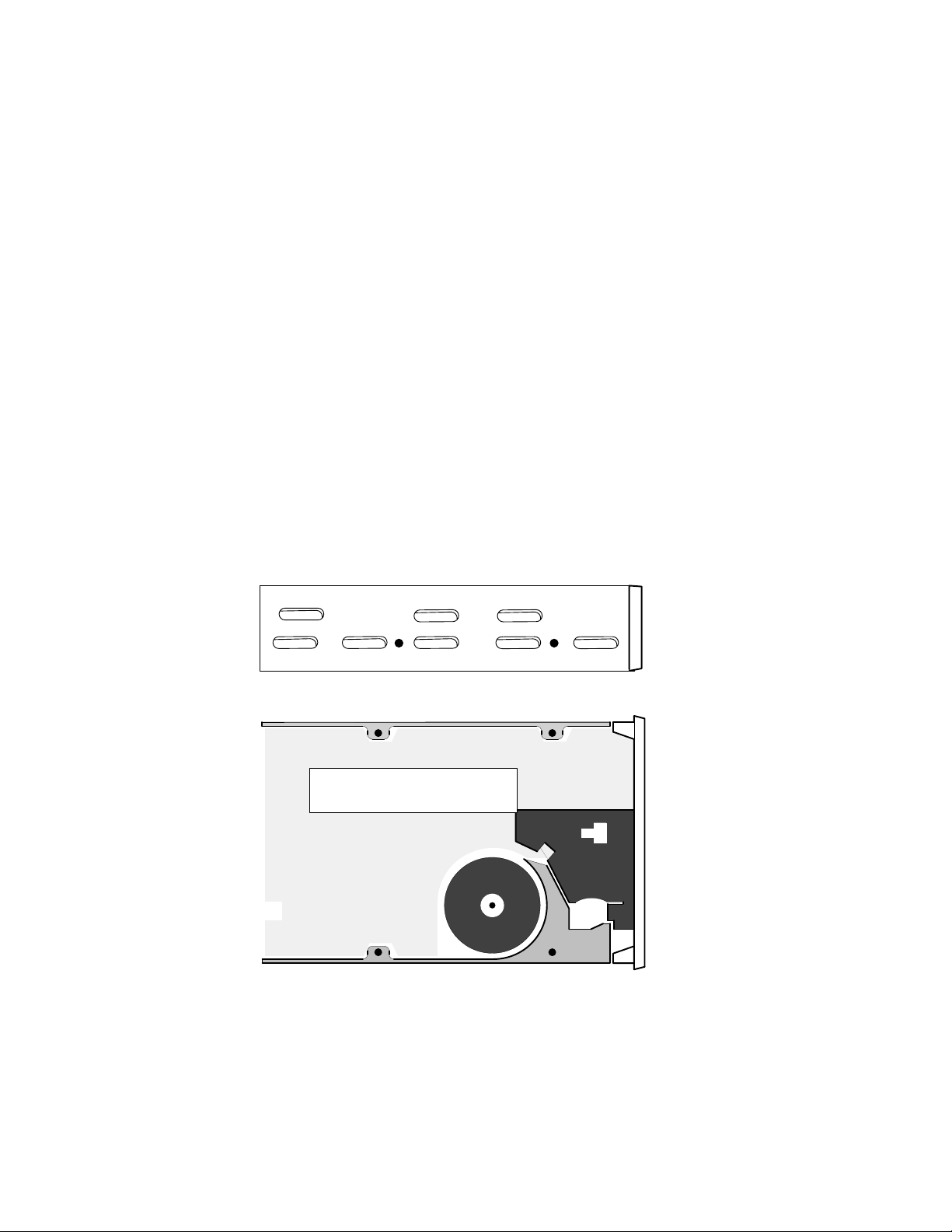
Figure 3 shows the four mounting–screw holes on the side and the bottom of the
drive. The mounting holes you use (side or bottom) and the orientation of the drive
(horizontal or vertical) depend on the computer or mass–storage subsystem in which
you will install the drive. Read the installing, maintaining, or expanding manual
for your computer or mass–storage subsystem. It shows you where to install a
half–height drive, and how to orient and attach it. Carefully follow all procedures
for installing a drive, and make sure you have turned off the computer or
mass–storage subsystem and unplugged its power cord before removing any covers.
Four mounting–screw holes
(two on each side)
Four mounting–screw holes
(on bottom)
Figure 3 Mounting–Screw Holes for Attaching the Tape Drive Inside the Computer or
Mass–Storage Subsystem
Once you have installed the drive, connect the power cable and SCSI bus cable to
the connectors shown in Figure 4. Make sure that you plug the SCSI bus cable into
the drive so that the red stripe on the cable lines up with Pin 1 on the connector.
(Most cables are keyed so that you cannot install them improperly.) You will find the
power cable and SCSI bus cable inside your computer or mass–storage subsystem.
6
014–001953
Page 13

Power cable
(provided by the computer
or mass–storage subsystem)
Installing the Drive
SCSI–bus cable
(provided by the computer
or mass–storage subsystem)
Red stripe = pin 1
Figure 4 Connecting the Cables
DG/UX Operating System Requirements
Once you have installed and cabled your cartridge tape drive and have closed the
computer or mass–storage subsystem chassis, refer to your operating system
manual. You will need to rebuild and reboot your DG/UX operating system.
014–001953
7
Page 14

Operating the Drive
This section describes how to write–protect and insert or remove a tape cartridge. It
also provides information on resolving simple problems that may occur during
operation.
Using and Write–Protecting a Cartridge Tape
The cartridge is available from Data General in four tape capacities: 60 Mbytes,
125 Mbytes, 150 Mbytes, and 320/525 Mbytes. Each cartridge tape comes in a
protective plastic case. Keep the cartridge in the case when it is not in use.
When storing cartridges, make sure the storage area is clean, dry and away from
direct sunlight, high humidity, and extreme temperatures– not below 5° C (41° F)
and not above 45° C (113° F). Do not place or store cartridges near magnets or
equipment that generate magnetic fields, such as telephones, power supplies,
printers, or display monitors. Before using a cartridge tape that was moved from a
warmer or colder location, for example a car , allow the cartridge to acclimate for
approximately the same amount of time that it was exposed to the warmer or colder
location. It is not necessary to acclimate the cartridge for more than 24 hours.
When handling cartridge tapes, never expose or touch the magnetic tape. Dirt or oil
from your fingers can make data on the tape unreadable by the drive. Never drop,
toss, or handle a cartridge carelessly. Operate a cartridge tape in the drive only
within the following ambient temperature and relative humidity ranges:
Temperature 5° C – 45° C
Relative Humidity 20%–80% (noncondensing) maximum
Do not read or write a cartridge tape when the ambient temperature is changing at
the rate of 6° C (108° F) /hour.
Your cartridge tape has a write–protect indicator. When you rotate the indicator
clockwise so that it points to the word SAFE (Figure 5), the system can read data
from the cartridge tape, but cannot write data or alter data on the cartridge tape.
When you rotate the write–protect indicator counterclockwise so that it points away
from the word SAFE, the system can read, write and alter cartridge tape data.
8
014–001953
Page 15

Coin or
similar tool
Write protect indicator
Operating the Drive
Write–enabled Write–protected
Figure 5 Write–Protecting 1/4–inch Cartridge Tape
Loading a Cartridge Tape
1. Turn on the power to the computer system or mass–storage subsystem, as
described in your computer or mass–storage subsystem installation or
expanding manual.
2. Remove the tape from its plastic protective case.
3. Rotate the protect switch on the tape cartridge (Figure 5) to the position that
you want.
4. Press the eject button shown in Figure 6 to open the drive door.
Multicapacity cartridge
tape drive, horizontally
mounted
Eject button
Eject button
Multicapacity cartridge
tape drive, vertically
mounted
014–001953
Drive Busy
LED
Drive Busy
LED
Figure 6 Eject Button and Tape Busy LED
9
Page 16

Operating the Drive
5. Hold the cartridge tape with the metal plate oriented as shown in Figure 7.
Gently push the cartridge tape into the drive opening; then push firmly all the
way into the drive. Close the drive door.
Cartridge tape drive,
vertically mounted
1/4–inch cartridge tape
Metal plate
Cartridge tape drive,
horizontally mounted
1/4–inch cartridge tape
Metal plate
Figure 7 Inserting a Cartridge Tape into the Tape Drive
As you push the cartridge into the drive’s cartridge–insertion slot, the drive
pulls in the cartridge and automatically positions it. The green drive–busy LED
(Figure 6) lights to indicate that the drive is checking the format of the
cartridge tape and is positioning the tape at the “Logical Beginning of Tape”
position. This check takes about 10 –12 seconds. If the drive and its LED do
not behave in this manner , refer to the section “Solving Operating Problems.”
NOTE: If the tape is blank, the drive automatically initializes (formats)
the tape during the first write operation. This procedure takes
about 30 additional seconds. When the drive finishes initializing
the tape, the green LED goes out. If you eject the tape before it is
10
014–001953
Page 17

Operating the Drive
initialized, the drive aborts this procedure, making it necessary to
initialize the tape again from the beginning the next time the
drive writes to this tape.
The green drive–busy LED lights when the drive reads or writes to the
cartridge tape. Never eject the cartridge tape when the drive–busy indicator is
lit. Once you have loaded the cartridge tape into the drive, refer to your
operating system manual for the commands that allow you to read or write the
cartridge tape.
Removing a Cartridge Tape
If you are using the AOS/VS or AOS/VS II operating system, follow the steps in the
next section to remove the cartridge tape. If you are using the DG/UX operating
system, follow the steps in the section “For DG/UX Operating System Users.”
For AOS/VS or AOS/VS II Operating System Users
1. If you have initialized the cartridge tape in your drive using the CLI command
INITIALIZE, release the logical disk using the CLI command RELEASE. The
manual Using the CLI (AOS/VS and AOS/VS II) and the installing manual
for your AOS/VS or AOS/VS II operating system describe these commands.
2. Press the cartridge eject button (Figure 6). When you do, the cartridge tape
will eject part way out of the opening of the drive.
3. Grasp the cartridge at the center, and pull it out of the drive.
4. Store the cartridge tape in its protective plastic case when you are not using it.
For DG/UX Operating System Users
1. Press the cartridge eject button shown in Figure 6. When you do, the tape
cartridge will slide part way out of the opening of the drive.
2. Grasp the cartridge at the center, and pull it out of the drive.
3. Store the cartridge tape in its protective packaging in a safe place.
Cleaning the Tape Drive Head
Dirt and dust can collect on the tape drive head and interfere with the transfer of
information or even destroy it. You must clean the tape path and heads routinely
after about 8 hours of operation or at least once a month, whichever occurs first.
Also, clean the tape path and head if a tested–and–checked tape cartridge
experiences slow read/write performance or read/write errors.
To clean the drive you must have the Data General Model 18933 Tape Cleaning Kit.
The kit contains a special cleaning cartridge, cleaning fluid, 25 sponge pads for the
cleaning cartridge, and a pair of tweezers. The following steps explain how to install
a cleaning cartridge and clean the drive. The section “Removing a Cleaning Pad
from the Cleaning Cartridge” describes how to remove the cleaning cartridge pad.
014–001953
11
Page 18
Operating the Drive
ÄÄÄ
ÄÄÄ
1. Power up the cartridge tape drive.
If there is a cleaning pad already installed in the cleaning cartridge ensure that
a clean surface of the pad faces out from the cartridge. If the side facing out is
dirty remove the pad following the steps in the section “Removing a Cleaning
Pad from the Cleaning Cartridge.”
CAUTION: Each cleaning pad can be used only once on each side. The special
cleaning tape picks up dirt and oxide particles as it cleans.
Running a dirty pad through the tape path will not clean it
effectively and may actually expose the rotary heads and path to
more dirt and wear.
2. Release the tab on the tape cleaning cartridge rod from the slot in the tape
cleaning cartridge as shown in Figure 8.
Figure 8 Releasing the Tab on the Tape Cleaning Cartridge Rod from the Slot in the
Tape Cleaning Cartridge
3. Insert a pad with a clean surface facing away from the tape cleaning cartridge
as shown in Figure 9.
Figure 9 Inserting the Pad to the Cleaning Cartridge and Applying Isopropyl Alcohol
4. Insert the tab on the tape cleaning cartridge rod into the slot in the tape
cleaning cartridge as shown in Figure 9.
5. Moisten one side of the cleaning cartridge sponge pad with 12 drops of the
isopropyl alcohol as shown in Figure 9.
NOTE: Use only 91% isopropyl alcohol. Do not use rubbing alcohol.
12
014–001953
Page 19

Operating the Drive
6. Insert the cleaning cartridge in the drive as described in the section “Loading a
Cartridge T ape.” The cartridge tape drive senses the presence of the special
cleaning cartridge and begins the process of cleaning the tape path and rotary
heads. The cleaning process takes about 20 seconds.
7. Remove the cleaning cartridge from the drive as described in the section
“Removing a Cartridge Tape.”
8. Record the present date. By referring to this recorded date you will know when
the next monthly cleaning is required. A Data General cleaning cartridge
provides about 40 uses. Always have a new cleaning cartridge on hand.
9. Store the cleaning cartridge in its protective case in a convenient place for
future use. After you have used up the cleaning cartridge, discard it and
replace it with a new one.
Removing a Cleaning Pad from the Cleaning
Cartridge
1. Release the tab on the tape cleaning cartridge rod from the slot in the tape
cleaning cartridge as shown in Figure 10.
Figure 10 Removing the Pad from the Cleaning Cartridge
2. Remove the pad from the rod as shown in Figure 10. If the pad is used up on both
sides, discard it.
3. Install a new pad as described in the section “Installing a Cleaning Pad in the
Cleaning Cartridge.”
Solving Operating Problems
This section provides suggestions for solving common problems that you may
encounter. If you cannot resolve the problem yourself, contact Data General as
described in the section “About This Document.”
If the cartridge tape drive LED indicator blinks it does not indicate an operating
problem. The cartridge tape drive LED indicator should briefly blink as the
computer runs its self–test.
014–001953
13
Page 20

Operating the Drive
Cannot insert cartridge
• Make sure a tape cartridge is not already installed in the drive.
• You may have a tape drive failure. Contact Data General.
Cannot eject cartridge
• Make sure the computer or mass–storage subsystem’s power is on.
• If you initialized the tape cartridge, make sure you have released the tape
cartridge before attempting to eject the cartridge.
• You may have a tape drive failure. Contact Data General.
“Physical–unit failure” message
• You may have ejected the cartridge before releasing it. Reinsert the cartridge and
refer to the AOS/VS or AOS/VS II operating system manual for the procedure to
correct this condition.
• You may have a tape drive failure. Contact Data General.
“Hard write–protected” message
• You may have tried to write to a write–protected cartridge. Release or unmount
the cartridge, eject the tape cartridge, change the write–protection switch, and
reinsert the cartridge.
• You may have a tape drive failure. Contact Data General.
End of Document
14
014–001953
Page 21

Index
Within the index, a range of page numbers indicates the reference spans those
pages.
avoiding electrostatic discharge (ESD)
damage, v
cables, connecting, 6–7
cartridge tape drive
cleaning, 11–13
installation requirements, 1–2
installing, 6–7
setting jumpers, 3–5
specifications, 1
unpacking, 2–3
cartridge tapes
ejecting, 11
inserting, 9
specifications, 1
storing, 8
write–protecting, 8–9
connecting cables, 6–7
inserting cartridge tape, 9–11
inspecting the drive, 2–3
installing
cleaning pad in the cleaning
cartridge, 11–13
drive terminator resistors, 5
jumpers, 3–5
tape drive, 6–7
jumpers, installing and removing, 3–5
loading, cartridge tapes, 9–11
operating system requirements, 7
drive specifications, 1
drive terminator resistors, installing or
removing, 5
ejecting, cartridge tape, 11
electrostatic discharge (ESD) damage,
avoiding, v
hardware requirements
for AViiON computer systems, 2
for ECLIPSE computer systems, 2
014–001953
removing
cleaning pad from the cleaning
cartridge, 13
drive terminator resistors, 5
jumpers, 3–5
requirements
for installing, 1–2
operating system, 7
software requirements
for AViiON computer systems, 2
for ECLIPSE computer systems, 2
solving problems, telephone assistance,
v
specifications, 1
Index-1
Page 22

tape specifications, 1
troubleshooting
operation problems, 13–14
telephone assistance, v
unpacking the drive, 2–3
write–protecting, 8–9
Index-2
014–001953
 Loading...