


Manual Datafox ZK-MasterIV
Datafox ZK-MasterIV
Access only for authorized persons
Version: 04.01.07.00 Page 1 www.datafox.de

Manual Datafox ZK-MasterIV
Contents
1 Introduction 7
1.1 Updates in this document . . . . . . . . . . . . . . . . . . . . . . . . . . . . . . . . . . . . 7
1.2 Alterations of the version . . . . . . . . . . . . . . . . . . . . . . . . . . . . . . . . . . . . 7
1.3 The device file archive (*.dfz) . . . . . . . . . . . . . . . . . . . . . . . . . . . . . . . . . . 7
1.3.1 Description . . . . . . . . . . . . . . . . . . . . . . . . . . . . . . . . . . . . . . . . 7
1.3.2 Function of the archive . . . . . . . . . . . . . . . . . . . . . . . . . . . . . . . . . . 7
1.3.3 Manual selection of a file . . . . . . . . . . . . . . . . . . . . . . . . . . . . . . . . . 7
1.4 Typography of the manual . . . . . . . . . . . . . . . . . . . . . . . . . . . . . . . . . . . . 8
1.5 Important general advice . . . . . . . . . . . . . . . . . . . . . . . . . . . . . . . . . . . . . 9
2 System structure and functional principle 11
2.1 Software versions and compatibility of device firmware and setup . . . . . . . . . . . . . . 11
2.2 Firmware . . . . . . . . . . . . . . . . . . . . . . . . . . . . . . . . . . . . . . . . . . . . . 13
2.2.1 Firmware update . . . . . . . . . . . . . . . . . . . . . . . . . . . . . . . . . . . . . 13
2.2.2 Firmware downgrade . . . . . . . . . . . . . . . . . . . . . . . . . . . . . . . . . . . 13
2.3 System structure . . . . . . . . . . . . . . . . . . . . . . . . . . . . . . . . . . . . . . . . . 14
2.3.1 Device functions . . . . . . . . . . . . . . . . . . . . . . . . . . . . . . . . . . . . . 14
2.3.2 Communication . . . . . . . . . . . . . . . . . . . . . . . . . . . . . . . . . . . . . . 14
3 ZK-MasterIV 18
3.1 Technical data . . . . . . . . . . . . . . . . . . . . . . . . . . . . . . . . . . . . . . . . . . 18
3.2 Connection . . . . . . . . . . . . . . . . . . . . . . . . . . . . . . . . . . . . . . . . . . . . 19
3.2.1 Power supply . . . . . . . . . . . . . . . . . . . . . . . . . . . . . . . . . . . . . . . 22
3.2.2 Digital Input . . . . . . . . . . . . . . . . . . . . . . . . . . . . . . . . . . . . . . . 22
3.2.3 USB connector . . . . . . . . . . . . . . . . . . . . . . . . . . . . . . . . . . . . . . 23
3.2.4 Ethernet interface . . . . . . . . . . . . . . . . . . . . . . . . . . . . . . . . . . . . 23
3.2.5 Mobile communications modem . . . . . . . . . . . . . . . . . . . . . . . . . . . . . 23
3.3 Commissioning . . . . . . . . . . . . . . . . . . . . . . . . . . . . . . . . . . . . . . . . . . 24
3.4 Operation . . . . . . . . . . . . . . . . . . . . . . . . . . . . . . . . . . . . . . . . . . . . . 24
3.5 Communications . . . . . . . . . . . . . . . . . . . . . . . . . . . . . . . . . . . . . . . . . 24
3.5.1 Communication via RS232 . . . . . . . . . . . . . . . . . . . . . . . . . . . . . . . . 24
3.5.1.1 Requirement . . . . . . . . . . . . . . . . . . . . . . . . . . . . . . . . . . 24
3.5.1.2 Connection . . . . . . . . . . . . . . . . . . . . . . . . . . . . . . . . . . . 24
3.5.1.3 Conversion of RS232 to RS485 . . . . . . . . . . . . . . . . . . . . . . . . 25
3.5.2 Communication via USB . . . . . . . . . . . . . . . . . . . . . . . . . . . . . . . . . 27
3.5.2.1 Conditions . . . . . . . . . . . . . . . . . . . . . . . . . . . . . . . . . . . 27
3.5.2.2 Connection . . . . . . . . . . . . . . . . . . . . . . . . . . . . . . . . . . . 27
3.5.2.3 Driver installation . . . . . . . . . . . . . . . . . . . . . . . . . . . . . . . 27
3.5.2.4 USB stick as data medium . . . . . . . . . . . . . . . . . . . . . . . . . . 30
3.5.2.4.1 Data structure and security . . . . . . . . . . . . . . . . . . . . . 30
3.5.2.4.2 Change the password of the communication . . . . . . . . . . . . 33
3.5.3 Communication via analogous modem . . . . . . . . . . . . . . . . . . . . . . . . . 34
3.5.3.1 Conditions . . . . . . . . . . . . . . . . . . . . . . . . . . . . . . . . . . . 34
3.5.3.2 Connection . . . . . . . . . . . . . . . . . . . . . . . . . . . . . . . . . . . 34
3.5.3.3 Modem initialization . . . . . . . . . . . . . . . . . . . . . . . . . . . . . . 37
3.5.3.4 Connection via the DatafoxStudioIV . . . . . . . . . . . . . . . . . . . . . 37
3.5.3.5 Connection via the DFComDLL . . . . . . . . . . . . . . . . . . . . . . . 38
3.5.4 Communication via GSM or GPRS/GSM . . . . . . . . . . . . . . . . . . . . . . . 39
3.5.4.1 Preparation . . . . . . . . . . . . . . . . . . . . . . . . . . . . . . . . . . . 39
Version: 04.01.07.00 Page 2 www.datafox.de

Manual Datafox ZK-MasterIV
3.5.4.2 Configuration . . . . . . . . . . . . . . . . . . . . . . . . . . . . . . . . . . 39
3.5.4.3 Connection state . . . . . . . . . . . . . . . . . . . . . . . . . . . . . . . . 40
3.5.4.4 Send data via GPRS . . . . . . . . . . . . . . . . . . . . . . . . . . . . . . 41
3.5.5 Communication via TCP/IP . . . . . . . . . . . . . . . . . . . . . . . . . . . . . . 43
3.5.5.1 LAN . . . . . . . . . . . . . . . . . . . . . . . . . . . . . . . . . . . . . . . 44
3.5.5.2 Transition from TCP/IP to RS232 . . . . . . . . . . . . . . . . . . . . . . 45
3.5.5.3 Transition from TCP/IP to RS485 Bus . . . . . . . . . . . . . . . . . . . 46
3.5.5.4 WLAN . . . . . . . . . . . . . . . . . . . . . . . . . . . . . . . . . . . . . 47
3.5.6 Communication via RS485 . . . . . . . . . . . . . . . . . . . . . . . . . . . . . . . . 47
3.5.7 Active connection via TCP/IP . . . . . . . . . . . . . . . . . . . . . . . . . . . . . 48
3.5.7.1 Description . . . . . . . . . . . . . . . . . . . . . . . . . . . . . . . . . . . 48
3.5.7.2 Configuration of an active connection . . . . . . . . . . . . . . . . . . . . 49
3.5.7.3 Device servicing via active connection . . . . . . . . . . . . . . . . . . . . 51
3.5.8 WLAN . . . . . . . . . . . . . . . . . . . . . . . . . . . . . . . . . . . . . . . . . . 53
3.5.8.1 General information . . . . . . . . . . . . . . . . . . . . . . . . . . . . . . 53
3.5.8.2 Terms and explanations . . . . . . . . . . . . . . . . . . . . . . . . . . . . 53
3.5.8.2.1 Infrastructure Mode . . . . . . . . . . . . . . . . . . . . . . . . . 53
3.5.8.2.2 Ad-hoc Mode . . . . . . . . . . . . . . . . . . . . . . . . . . . . . 53
3.5.8.2.3 Frequencies and ports . . . . . . . . . . . . . . . . . . . . . . . . 54
3.5.8.2.4 Security and encryption . . . . . . . . . . . . . . . . . . . . . . . 54
3.5.8.2.5 Authentification . . . . . . . . . . . . . . . . . . . . . . . . . . . 54
3.5.8.2.6 Passwords . . . . . . . . . . . . . . . . . . . . . . . . . . . . . . . 55
3.5.8.3 BIOS dialogue DatafoxStudioIV . . . . . . . . . . . . . . . . . . . . . . . 55
3.5.8.4 Dependencies . . . . . . . . . . . . . . . . . . . . . . . . . . . . . . . . . . 56
3.5.8.5 WLAN configuration via the Lantronix tool . . . . . . . . . . . . . . . . . 56
3.5.8.6 WLAN configuration via the DatafoxStudioIV . . . . . . . . . . . . . . . 57
3.5.8.6.1 General . . . . . . . . . . . . . . . . . . . . . . . . . . . . . . . . 57
3.5.8.6.2 Selection of the serial interface . . . . . . . . . . . . . . . . . . . 57
3.5.8.6.3 Selection of the configuration file . . . . . . . . . . . . . . . . . . 58
3.5.8.6.4 TCP/IP settings . . . . . . . . . . . . . . . . . . . . . . . . . . . 59
3.5.8.6.5 WLAN settings . . . . . . . . . . . . . . . . . . . . . . . . . . . . 59
3.6 Access control II with TS TMR33 modules . . . . . . . . . . . . . . . . . . . . . . . . . . . 61
3.6.1 Set-up . . . . . . . . . . . . . . . . . . . . . . . . . . . . . . . . . . . . . . . . . . . 61
3.6.1.1 A door without a separate reader . . . . . . . . . . . . . . . . . . . . . . . 62
3.6.1.2 A door with a separate reader . . . . . . . . . . . . . . . . . . . . . . . . 62
3.6.1.3 Several external doors via RS485 bus . . . . . . . . . . . . . . . . . . . . 63
3.6.1.4 Several internal doors via RS485 bus . . . . . . . . . . . . . . . . . . . . . 64
3.6.1.5 Mantrap function with RS485 bus . . . . . . . . . . . . . . . . . . . . . . 65
3.6.2 Connection . . . . . . . . . . . . . . . . . . . . . . . . . . . . . . . . . . . . . . . . 66
3.6.2.1 Wiring . . . . . . . . . . . . . . . . . . . . . . . . . . . . . . . . . . . . . 67
3.6.2.2 Calculation instructions . . . . . . . . . . . . . . . . . . . . . . . . . . . . 73
3.6.2.3 Topologie . . . . . . . . . . . . . . . . . . . . . . . . . . . . . . . . . . . . 74
3.6.2.4 Examples . . . . . . . . . . . . . . . . . . . . . . . . . . . . . . . . . . . . 74
3.6.2.4.1 Bus topology . . . . . . . . . . . . . . . . . . . . . . . . . . . . . 74
3.6.2.4.2 Star topology . . . . . . . . . . . . . . . . . . . . . . . . . . . . . 75
3.6.3 Configuration . . . . . . . . . . . . . . . . . . . . . . . . . . . . . . . . . . . . . . . 76
3.6.4 An example for a ZK system . . . . . . . . . . . . . . . . . . . . . . . . . . . . . . 80
3.7 Timing of the digital exits for the MasterIV device s eries . . . . . . . . . . . . . . . . . . . 86
3.8 Access control II with PHG modules . . . . . . . . . . . . . . . . . . . . . . . . . . . . . . 88
3.8.1 Connection . . . . . . . . . . . . . . . . . . . . . . . . . . . . . . . . . . . . . . . . 89
Version: 04.01.07.00 Page 3 www.datafox.de

Manual Datafox ZK-MasterIV
3.8.2 Configuration . . . . . . . . . . . . . . . . . . . . . . . . . . . . . . . . . . . . . . . 90
3.9 Status message of the access control . . . . . . . . . . . . . . . . . . . . . . . . . . . . . . 91
4 DatafoxStudioIV - General operation 93
4.1 Installation . . . . . . . . . . . . . . . . . . . . . . . . . . . . . . . . . . . . . . . . . . . . 93
4.2 Operation of the DatafoxStudioIV . . . . . . . . . . . . . . . . . . . . . . . . . . . . . . . 93
4.3 Menu Datei . . . . . . . . . . . . . . . . . . . . . . . . . . . . . . . . . . . . . . . . . . . . 94
4.3.1 Creating a new setup file . . . . . . . . . . . . . . . . . . . . . . . . . . . . . . . . . 94
4.3.2 Open setup file . . . . . . . . . . . . . . . . . . . . . . . . . . . . . . . . . . . . . . 95
4.4 Menu Setup . . . . . . . . . . . . . . . . . . . . . . . . . . . . . . . . . . . . . . . . . . . . 96
4.4.1 Edit . . . . . . . . . . . . . . . . . . . . . . . . . . . . . . . . . . . . . . . . . . . . 96
4.4.2 Import access control lists . . . . . . . . . . . . . . . . . . . . . . . . . . . . . . . . 96
4.4.3 Configure data storage . . . . . . . . . . . . . . . . . . . . . . . . . . . . . . . . . . 97
4.4.4 Load firmware . . . . . . . . . . . . . . . . . . . . . . . . . . . . . . . . . . . . . . 98
4.4.5 Device maintenance via modem connection . . . . . . . . . . . . . . . . . . . . . . 99
4.4.5.1 Functions for device maintenance . . . . . . . . . . . . . . . . . . . . . . . 100
4.4.6 Edit text data of the firmware . . . . . . . . . . . . . . . . . . . . . . . . . . . . . . 102
4.5 Menu Communication . . . . . . . . . . . . . . . . . . . . . . . . . . . . . . . . . . . . . . 105
4.5.1 Write / read setup . . . . . . . . . . . . . . . . . . . . . . . . . . . . . . . . . . . . 105
4.5.2 Load lists/ access control lists . . . . . . . . . . . . . . . . . . . . . . . . . . . . . . 105
4.5.3 Import and load Timeboy lists . . . . . . . . . . . . . . . . . . . . . . . . . . . . . 106
4.5.4 Read, delete, display data . . . . . . . . . . . . . . . . . . . . . . . . . . . . . . . . 107
4.5.4.1 Read data and delete them . . . . . . . . . . . . . . . . . . . . . . . . . . 107
4.5.5 Set time . . . . . . . . . . . . . . . . . . . . . . . . . . . . . . . . . . . . . . . . . . 107
4.5.6 Read serial number . . . . . . . . . . . . . . . . . . . . . . . . . . . . . . . . . . . . 107
4.5.7 Read global variables . . . . . . . . . . . . . . . . . . . . . . . . . . . . . . . . . . . 108
4.5.8 System variables of the signal processing . . . . . . . . . . . . . . . . . . . . . . . . 109
4.5.9 Display state of the ZK-mo dules . . . . . . . . . . . . . . . . . . . . . . . . . . . . 110
4.5.10 Work through batches . . . . . . . . . . . . . . . . . . . . . . . . . . . . . . . . . . 111
4.5.11 GPRS configuration . . . . . . . . . . . . . . . . . . . . . . . . . . . . . . . . . . . 112
4.5.12 Device configuration BIOS . . . . . . . . . . . . . . . . . . . . . . . . . . . . . . . . 114
4.5.13 Settings . . . . . . . . . . . . . . . . . . . . . . . . . . . . . . . . . . . . . . . . . . 117
4.6 Menu Extra . . . . . . . . . . . . . . . . . . . . . . . . . . . . . . . . . . . . . . . . . . . . 119
5 DatafoxStudioIV - Setup 120
5.1 Basics . . . . . . . . . . . . . . . . . . . . . . . . . . . . . . . . . . . . . . . . . . . . . . . 120
5.1.1 Planning . . . . . . . . . . . . . . . . . . . . . . . . . . . . . . . . . . . . . . . . . . 120
5.2 Functions of a setup . . . . . . . . . . . . . . . . . . . . . . . . . . . . . . . . . . . . . . . 122
5.2.1 Basic settings . . . . . . . . . . . . . . . . . . . . . . . . . . . . . . . . . . . . . . . 122
5.2.2 Global variables . . . . . . . . . . . . . . . . . . . . . . . . . . . . . . . . . . . . . . 122
5.2.3 Transponder . . . . . . . . . . . . . . . . . . . . . . . . . . . . . . . . . . . . . . . 123
5.2.3.1 Transponder reading systems . . . . . . . . . . . . . . . . . . . . . . . . . 125
5.2.3.2 Function upgrading for Mifare transponders . . . . . . . . . . . . . . . . . 131
5.2.3.2.1 General information . . . . . . . . . . . . . . . . . . . . . . . . . 131
5.2.3.2.2 Global settings . . . . . . . . . . . . . . . . . . . . . . . . . . . . 131
5.2.3.2.3 Function normal . . . . . . . . . . . . . . . . . . . . . . . . . . . 134
5.2.3.2.4 Transponder value write, also for Hitag1, Hitag2 and Titan . . . 134
5.2.3.2.5 Transponder menu . . . . . . . . . . . . . . . . . . . . . . . . . . 134
5.2.3.3 Application possibilities for Hitag-transponder . . . . . . . . . . . . . . . 135
5.2.4 Creating data record descriptions . . . . . . . . . . . . . . . . . . . . . . . . . . . . 137
5.2.5 Creating list descriptions . . . . . . . . . . . . . . . . . . . . . . . . . . . . . . . . 138
Version: 04.01.07.00 Page 4 www.datafox.de

Manual Datafox ZK-MasterIV
5.2.6 Creating a user guidance . . . . . . . . . . . . . . . . . . . . . . . . . . . . . . . . . 139
5.2.6.1 Defining input chains . . . . . . . . . . . . . . . . . . . . . . . . . . . . . 139
5.2.6.2 Defining input fields . . . . . . . . . . . . . . . . . . . . . . . . . . . . . . 140
5.2.6.2.1 Field functions in general . . . . . . . . . . . . . . . . . . . . . . 141
5.2.6.2.2 Field functions of the access control . . . . . . . . . . . . . . . . 142
5.2.6.3 Expanded . . . . . . . . . . . . . . . . . . . . . . . . . . . . . . . . . . . . 142
5.2.6.4 Reaction on list selection . . . . . . . . . . . . . . . . . . . . . . . . . . . 143
5.2.6.5 Jumps . . . . . . . . . . . . . . . . . . . . . . . . . . . . . . . . . . . . . . 143
5.2.7 Signal processing . . . . . . . . . . . . . . . . . . . . . . . . . . . . . . . . . . . . . 143
5.2.7.1 Use as Start/Stop . . . . . . . . . . . . . . . . . . . . . . . . . . . . . . . 143
5.2.7.2 Use as counter . . . . . . . . . . . . . . . . . . . . . . . . . . . . . . . . . 144
5.2.7.3 Use as counter with Start/Stop . . . . . . . . . . . . . . . . . . . . . . . . 145
5.2.7.4 Use as counter with Start/Stop via timeout . . . . . . . . . . . . . . . . . 145
5.2.7.5 Use as counter with Start/Stop via timeout and 1st counting impulse . . 146
5.2.7.6 Connection Timeboy . . . . . . . . . . . . . . . . . . . . . . . . . . . . . . 147
5.2.7.7 Alive data record . . . . . . . . . . . . . . . . . . . . . . . . . . . . . . . . 147
5.2.7.8 Setting of timers . . . . . . . . . . . . . . . . . . . . . . . . . . . . . . . . 147
5.2.7.9 Setting of timers . . . . . . . . . . . . . . . . . . . . . . . . . . . . . . . . 147
5.2.8 Mathematical operations . . . . . . . . . . . . . . . . . . . . . . . . . . . . . . . . . 147
5.3 Creating setups . . . . . . . . . . . . . . . . . . . . . . . . . . . . . . . . . . . . . . . . . . 149
5.3.1 Setup for access control version II . . . . . . . . . . . . . . . . . . . . . . . . . . . . 149
5.3.1.1 General . . . . . . . . . . . . . . . . . . . . . . . . . . . . . . . . . . . . . 149
5.3.1.2 Hardware components of access control system . . . . . . . . . . . . . . . 149
5.3.1.3 Basic settings . . . . . . . . . . . . . . . . . . . . . . . . . . . . . . . . . . 150
5.3.1.4 Creating a data record description . . . . . . . . . . . . . . . . . . . . . . 151
5.3.1.5 Creating the access control lists . . . . . . . . . . . . . . . . . . . . . . . 152
5.3.1.6 Creating an input chain of access control . . . . . . . . . . . . . . . . . . 154
5.3.1.7 Transmission of the complete configuration to the terminal . . . . . . . . 157
Version: 04.01.07.00 Page 5 www.datafox.de

Manual Datafox ZK-MasterIV
c
2008 by Datafox GmbH
This document has been created by Datafox GmbH and is copyrighted against third parties. Datafox
GmbH considers all contained information, knowledge and depictions as its sole property. All rights,
including also translation, reprint or copy of the whole document or parts of it, require written consent of
Datafox GmbH. The assertion of all rights in this respect is reserved to Datafox GmbH, especially in case
of the grant of a patent. The handover of this documentation does not establish a claim to the licence
or the use the soft- and hardware. Copies of the diskettes and CDs may only be made for the purpose of
data backup. Every unauthorized copy of this documentation or the Datafox-software will be prosecuted.
Version: 04.01.07.00 Page 6 www.datafox.de

Manual Datafox ZK-MasterIV
1 Introduction
1.1 Updates in this document
1.2 Alterations of the version
With the device generation IV a new versioning scheme has been introduced. According to this scheme
the file name of the device firmware and the setup program (DatafoxStudioIV) is composed as follows:
product name XX. YY. ZZ. Build
devicegeneration
e. g. ZK-MasterIV 04. 01. 01. 12
compatibility
(which versions
can be used
together)
version number
(functional extension)
Build troubleshooting
(with a new version the Build
number is reset)
The use of the manual depends on the version of the firmware and the DatafoxStudioIV or the DFComDLL.
Gather from the following table which manual matches which version. For different combinations no support can be offered.
version
date manual firmware Studio/DLL description
21. Dez. 2006 4.01.03 4.01.03 4.01.03 new release
06. Juni 2007 4.01.04.16 4.01.04.16 4.01.04.16 new release
1.3 The device file archive (*.d fz )
1.3.1 Description
Device files (*.hex) of the MasterIV - devices are delivered in a common device file archive. It has the file
extension dfz (stands for Datafox Zip). Now simply the device file archives are indicated instead of the
device files (*.hex). This applies to the DatafoxStudioIV and DLL. The indication of device files (*.hex)
is still possible.
1.3.2 Function of the archive
The transmission routine of the device file picks out the fitting file from the device file archive on the
basis of the hardware options available in the device. Thus, it is guaranteed that all hardware components
available in the device are supported by the corresponding firmware.
1.3.3 Manual selection of a file
If you do not want to integrate the archive in your installation, you have the possibility to add single
device files from the archive to the installation.
The file format of the device file archive is Zip. Hence, you can open the archive with every standard Zipprogram. Via the menu item "open with..." in the context menu you can chose an appropriate program
Version: 04.01.07.00 Page 7 www.datafox.de

Manual Datafox ZK-MasterIV
for opening the file. If necessary you can call up a program combined with this file format to open the
file by renaming the file from dfz to zip.
In the archive you find a file called Inhalt.pdf; you can gather from there which file (*.hex) of the archive
matches your device. Extract the device file (*.hex) you want and rename it if necessary. A renaming of
a file is always possible, because all information are in the file itself.
You can state the device file extracted before as device file in DatafoxStudioIV and at calling the DLL
function. It is still tested if the file can be loaded into the chosen device before the transmission takes
place.
1.4 Typography of the manual
exposition contextual meaning
ZK-MasterIV , SoftwareV ersion.pdf
Setup
edit
file names
a path via a program menu at DatafoxStudioIV
communication a single menu item
FW abbreviation for firmware (software in the device)
(from FW V 3.1.5) shows that this function is supported from the
firmware version 3.1.5 onwards
SW abbreviation for software
HW abbreviation for hardware
(from HW V 2.0) shows that this option is available from the
hardware version 2.0 onwards
GV abbreviation for global variable
ZK-list abbreviation for access control lists, where the
configuration data for the access control is
provided
cross-reference 1.4 In the electronic document you can use the
cross-references to jump within the manual.
Therefore, cross-references are depicted in blue
and crossing them the cursor takes the shape of a
hand .
You will get useful advice which helps you to avoid possible mistakes during the
installation, configuration and commissioning.
Version: 04.01.07.00 Page 8 www.datafox.de
Note:

Manual Datafox ZK-MasterIV
Caution:
There will be advice given you definitely have to keep to. Otherwise it will lead to
defective function of the system.
1.5 Important general advice
Caution:
Use the devices only according to regulations and following the assembly, commissioning and operating instructions. Assembly and commissioning may only be
carried out by authorized and qualified personnel.
Subject to technical alterations.
Caution:
Because of technical development illustrations, functional steps, technical process es
and data can differ slightly.
Datafox ZK-MasterIV has been developed to create a flexible terminal for time and attendance, order
time collection and access control that can easily be integrated. The device is robust and easy to use.
You save time through the PC - setup program, because the device is quickly and easily configured for
its application field.
This manual describes the creation of work flows for time and attendance with the setup
program.
Before deciding f or the programming in C you should check if the functions of the setup program do fulfil
the system requirements after all , because then the development effort will b e reduced to a minimum.
With some exercise it will be possible to compile a complete entry within half an hour. If you need
functions that are not available we should get into contact.
If you need support at the compilation of setups we offer you our services. Because of our wide experience
in dealing with the setup we are very quick and can make your setup even more efficient through useful
advice, so that the entry at the device can take place quickly and reliably.
Through our experience and with our specialized knowledge of method, hard- and software we produce
devices and find solutions concerning data collection, that prove themselves with functionality and practicality. We offer solutions for REFA/ job analysis, time and attendance, production data collection,
machine data collection, process data collection and mobile data collection. Out team develops and produces standardized and inexpensive systems. We create solutions using the modular principle and expand
them as required. Our service includes consultation, system definition and implementation as well as
workshops and training to support you in the introduction.
Guarantee restriction
Version: 04.01.07.00 Page 9 www.datafox.de

Manual Datafox ZK-MasterIV
All data in this manual has been checked carefully. Nevertheless, errors cannot be excluded. Therefore,
there cannot be given guarantee nor taken legal responsibility for consequences that derive from errors
of this manual. Of course we are grateful if you point out errors to us. Subject to change because of
technical improvements. Our general terms and conditions of business apply.
Note:
Because of the DatafoxStudioIV the Datafox devices have many functions and combination of functions; therefore, it is not possible to test all functions and their combinations in case of updates. This applies especially to all the setups you created as
a customer. Before updating your device please test if your individual setup works
without errors. If you detect an error contact us immediately. We will rectify the
mistake at short notice.
Version: 04.01.07.00 Page 10 www.datafox.de

Manual Datafox ZK-MasterIV
2 System structure and functional principle
2.1 Software versions and compatibility of devic e firmware and setup
The firmware (operating system) of the device and the setup program (*.aes data file = application program) form a unit. With the setup program the configuration for the device (definition of the data tables
and the data fields, operation, etc.) is compiled and transmitted to the device. Then the firmware works
in accordance with the setup adjustments.
Firmware in device
After switching-on the current firmware version
is shown on the display. The firmware can be
transmitted to the device with DatafoxStudioIV.
Setup program on PC
After starting the setup program the user interface
is displayed.
You can get information about the current software version via the info dialog of DatafoxStudioIV.
Click on the?in the menu bar and then on
inf o over DatafoxStudioIV..
At delivery a demo setup is at the device. The
description of the demo setup you will find in
chapter 5.3.1. It is advisable to go through the
example at first comparing the process with the
setup. That way a quick introduction to the
configuration is possible.
Version: 04.01.07.00 Page 11 www.datafox.de

Manual Datafox ZK-MasterIV
Compatibility of firmware and DatafoxStudioIV
The DatafoxStudioIV is downward compatible within the firmware versions 4.x.x x. The second number
shows the compatibility group. I f this number is changed, a more up-to-date firmware generation must
be used.
Devices with an older firmware can also be configured with DatafoxStudioIV, but
only that functions are provided by the device which are also provided by the older
firmware. However, it is impossible to configure a more up-to-date firmware version
with an older DatafoxStudioIV-Version.
That means, the manual version that corresponds to the firmware with the appropriate setup is always
relevant for the possible functions. The manual version and the appropriate DatafoxStudioIV always have
the same index. It is impossible to configure a firmware with a DatafoxStudioIV version that is older than
the firmware. Recommendation: If possible use the appropriate DatafoxStudioIV version. This version
always has to bethe version of the firmware.
Note:
The data file:
ZKMasterI V, Sof twareV ersionen S tand xxx.pdfshows which functions are provided
by which software release. You will find the file on the CD. Please alsocomply with the
instructions given in the chapters of the manual.
The updates are available for download on our internet p age www.datafox.de.
Caution:
When the new device is delivered always the firmware version recently released is
used. If you wish to work with an older version please carry out a downgrade.
Please comply with the instructions in chapter 2.2.2.
Version: 04.01.07.00 Page 12 www.datafox.de

Manual Datafox ZK-MasterIV
2.2 Firmware
Caution:
A firmware update or downgrade is a very sensitive process. Possibly a reset of
the main communication to RS232 may occur. In any case comply with the details
about the compatibility in the software version list.
2.2.1 Firmware update
Caution:
Before starting a firmware update please check on the basis of the software version
list whether there are any version dependencies that must be kept.
For example, when changing from version 04.00.xx to version 04.01.xx there must be a version 04.00.23.769
or higher as minimum requirement to carry out the update to version 04.01.xx successfully.
2.2.2 Firmware downgrade
Caution:
When carrying out a firmware downgrade the firmware always has to be transmitted
to the device twice. This has technical reasons. Errors on the display of the device
after the first transmission can be ignored.
Version: 04.01.07.00 Page 13 www.datafox.de

Manual Datafox ZK-MasterIV
2.3 System structure
2.3.1 Device functions
In principle, Datafox ZK-MasterIV offers two possibilities to create workflows for data collection.
Via the PC-setup program "‘DatafoxStudioIV"’ many processes for data collection can be created
quickly without programing knowledge. Such a process is a setup for the device and can be loaded
on the device via the communication program. Devices using such setup programs are equipped
with the standard firmware at production. (Details about the software versions see chapter 2.1)
Free Programming in C. The progression packet offers many basis routines and a supporting program
which can be used as basis for own programs. Devices for c-programming are delivered without the
standard firmware and only in connection with an instruction.
2.3.2 Communication
There are 4 possibilities available for communication/ data transmission.
1.) S etup- and communication program
The setup- and communication program supports both the setting of the device settings and the
important possibilities of data transmission (these data transmission functions are for test purposes
primarily). Of course they can also be used for regular data t ransmission. But this is disadvantageous, because 2 work steps are necessary: At first you have to read out the data via the setup- and
communication program and to file them as ASCII-file. Then the second program has to be opened
and the file must be imported.
Figure 1: Setup- and Communication programm
Version: 04.01.07.00 Page 14 www.datafox.de

Manual Datafox ZK-MasterIV
2.) Communication DLL
The direct way for communicating with the ... is the communication DLL. I t can b e started with
any Windows application. The whole process can be realized without any intermediate files and
also be set individually. We advise software producers to choose this method for the integration of
the devices. You can find the DLL and the appropriate explanation on the installing-CD.
Figure 2: Communication-DLL
3.) Direct integration via C-Source code
There are some operating systems that do not support the use of DLLs. In order to solve this
problem there is also a C-Source code available on the installing-CD. That way communicating with
programs designed under Unix or Linux is also possible.
Figure 3: Implementation via C-Sourcecode
4.) Datafox-Talk
Via Datafox-Talk data transmission with Datafox A EIII+, Timeboy and the MasterIV-series is
possible on file- and database layer. Therefore it is an alternative to communication via DLL. An
advantage of this method is, that no installation is necessary. The data are taken over and displayed
as ASCII-file. If desired and with computation a direct connection to databases is p ossible. There
the costumer has to decide which database tables and fields shall be filled. Datafox-Talk supports
all functions for transmitting data and for setting the device. Via timing the times for transmission
can be set freely. Via additional modules the data can also be transmitted per radio, internet,
telephone-/ mobile network.
Version: 04.01.07.00 Page 15 www.datafox.de

Manual Datafox ZK-MasterIV
Advantages:
Via Datafox-Talk integration of the devices can be realized easily and fast.
Transmission takes place automatically and is ensured via a log file.
The data are accessible forthwith.
There is no programming work for data transmission.
Figure 4: Datafox-Talk
Supports the following types of transmission:
RS232
RS485
TCP/IP
WLAN
Funk 433 MHz
Modem (GSM/GPRS)
Cellular radio, mobile phone with inte-
The following actions are possible:
Transmitting setup to the devices
Setting a clock
Transmitting lists to the devices
Reading out of data
Writing log files and error lists where necessary
Filing of data as ASCII-file, Excel-file,
Dbase-File or ACCESS-database
grated modem
The actions are applied as batch and carried out according to the settings of the timing. Timing allows
the permanent collection of data (polling) and the collection at any time. The setting via time model is
very easy. The working through the actions is logged and therefore always traceable. The same applies
to the transmission of lis ts. Lists are used e.g. to back-up applications, accounts, occupations etc. or to
transmit balances.
Version: 04.01.07.00 Page 16 www.datafox.de

Manual Datafox ZK-MasterIV
Figure 5: System structure
Version: 04.01.07.00 Page 17 www.datafox.de

Manual Datafox ZK-MasterIV
3 ZK-MasterIV
When using the ZK-MasterIV you have to comply with the temperature range of -20 to +70C, see data
sheet.
Caution:
Pleas keep in mind that MasterIV terminals use a flash memory. According to
the manufacturer each memory sector (512 byte) can be written to a maximum of
100,000 times. The firmware of the terminals distributes the access to the memory
sectors, this technique is called wear levelling. Bad blocks in case of write or read
failures are not used anymore. However, despite this technique it is not advisable
to write the memory too frequently. The application should initialize a new list
transfer only after a change of the list data but not cyclically.
Keep in mind the message - FlashService - in the display of the device. It
means that the live time of the flash memory according to the manufacturer
instruction will be reached soon. Then the device has to be sent to Datafox for
service.
3.1 Technical data
CPU Controller 8 bit, 16 MHz
Clock real-time-clock
Program memory Flash 128 Kbyte
Data memory Flash 2 MB Defaul
Memory extension Multi-Media-Card(MMC) up to 1 GB Flash
Power supply Power supply 24 volts of change tension or DC voltage
Lithium battery care of the clock with stream failure
Power consumtion Maximal 7,2 Watt
Basicdevice 4 Watt
Dimensions length x width x depth 205mm x 120mm x 40mm
Weight Without power supply 400 g
Environment factors Environmential temerature -20 to +70C
Protection class IP 40
Software Configuration program Setup program for arrangement witout programming
Communication tools Communication-DLL
Data transfer RS232 /RS485 RS232 und RS485 in basic unit
TCP-IP (option) TCP/IP use via integrated TCP/IP stack
WLAN (option) Wireless LAN via external ACCESS-Point
GSM/GPRS (option) mobile network via GSM and GPRS = online on internet
Bluetooth (option) bluetooth module integrated. Up to 100 meters.
Reader connection RS232 external connection from cash code reader , magnet card reader etc.
Access options RS485 extern Anschluß von bis zu 8 externen
Door module/access reader
door opener-relay 1 door opener-relay 42 Volt
digital input 1x door supervision
Options Transponder reader external Unique EM4102, Hitag, Legic, Mifare, SimonsVoss
Säule Säule für freies Aufstellen
Table 1: Technical data of the ZK-MasterIV HW-Version 2 Sub ject to technical alterations.
Version: 04.01.07.00 Page 18 www.datafox.de

Manual Datafox ZK-MasterIV
3.2 Connection
The ZK-MasterIV (central controller for access control, door- or rather remote control) has to be installed
in a safe area which is accessible only for authorized persons. You find the connections of the device
narrow sided over the edge connector. That way the installation of the device is easier.
Figure 6: ZK-MasterIV
Version: 04.01.07.00 Page 19 www.datafox.de

Manual Datafox ZK-MasterIV
3
12
4
5 6
Figure 7: Edge connector of the ZK-MasterIV from HW V 1.4
Designation Plug Pin Description
Power supply 4 5,8 12 V 3 A DC
Digital input
(this are potential-free
inputs)
4 3 Input 10 Hz
0 - 3 Volt = logical 0 (V
12-30 Volt = logical 1 (V
ILmax
IHmin
= 3,0 V )
= 12,0 V )
4 GND
Digital output 4 1 common (max. 2,0 A bei 42 V AC or 30 V DC)
2 Normally-open (Contact)
RS232 interface
D-Sub 9 pole
1 2 TxD
3 RxD
5 GND
RS485 interface 2 1 24 V DC
2 GND
3 Data channel B
4 Data channel B
5 Data channel A
6 Data channel A
RS485 interface
of the access control
4 5 GND
6 Data channel A
7 Data channel B
8 12 V DC
Table 2: Overview over connections with pin assignment HW V 1.4
Version: 04.01.07.00 Page 20 www.datafox.de

Manual Datafox ZK-MasterIV
2
8
1
3
9 4
5 67
10
Figure 8: Steckerleiste des ZK-MasterIV ab HW V 2.0
Designation Plug Pin Description
Power supply 8 24 V 300 mA AC/DC (If a DC voltage is
connected, the polarity is to be followed.)
Digital input
(this are potential-free
inputs)
4 3 Input 5 kHz
0 - 1 Volt = logical 0 (V
3,5 - 30 Volt = logical 1 (V
4 GND
ILmax
IHmin
= 1,0 V )
= 3,5 V )
10 3 Input 10 Hz
0 - 3 Volt = logical 0 (V
12-30 Volt = logical 1 (V
ILmax
IHmin
= 3,0 V )
= 12,0 V )
4 GND
Digital output 4 1 common (max. 2,0 A bei 42 V AC or 30 V DC)
2 Normally-open (Contact)
10 1 common (max. 2,0 A bei 42 V AC or 30 V DC)
2 Normally-open (Contact)
RS232 interface
D-Sub 9 pole
1 2 TxD
3 RxD
5 GND
RS485 interface 9 1 GND
2 Data channel A
3 Data channel B
4 24 V DC
RS485 interface
of the access control
4 5 GND
6 Data channel A
7 Data channel B
8 12 V DC
Table 3: Overview over connections with pin assignment HW V 2.0
Version: 04.01.07.00 Page 21 www.datafox.de

Manual Datafox ZK-MasterIV
3.2.1 Power supply
The power supply for the ZK-MasterIV (HW V 1.4) is connected to the Datafox device power supply unit
12 V 3 A DC via the 8 pole strip terminal, position (4) in figure 7. From HW V 2.0 on the terminal is
supplied with power (24 V 300 mA power supply unit) via the Molex connector (8) in figure 8.
Caution:
In principle, only one voltage source may be connected to the ZK-MasterIV. Only
a 12 V/3 A DC voltage source may be connected to the ZK-MasterIV with HW
V 1.4. The terminal and the entire access control-net (16 modules at most) can
be energized by this voltage source. You have to connect a 24 V/300 mA AC/DC
power supply unit to the ZK-MasterIV from HW V 2.0 on. By this power supply
unit one external reader at most may be powered via the RS285 B interface. Please
note the information in figure 52.
3.2.2 Digital Input
Examples for use the digital Input of the MasterIV terminals.
Note:
Pleas keep in mind, the 10-pole plug in the two figures below is not available by
every device.
Achtung:
Note in any case to proper ones Signals.
This example displays the possibility
for connection of potential-free contact
to the digital input.
Figure 9: Digital-Input potential-free
Version: 04.01.07.00 Page 22 www.datafox.de

Manual Datafox ZK-MasterIV
This example displays the possibility
for connection of a SPS with 24 V output (electricity of ca. 7 mA / port).
Figure 10: Digital-Input SPS
3.2.3 USB connector
The USB Type B connector (slave, no active USB controller) can optionally be led out of the device by
a USB cable through the edge connector. By this, the ZK-MasterIV can be connected to a PC as USB
terminal.
3.2.4 Ethernet interface
Caution:
Power over Ethernet (PoE) describes a process with which network-compatible devices can be energised via the 8-core Ethernet-wire. The internal TCP/IP module
of the ZK-MasterIV is not PoE tolerant.
The device can be integrated into a network of companies via TCP/IP via the RJ45 plug (2) in figure 7
and 8.
3.2.5 Mobile communications modem
At position (4) at figure 7 and 8 is the SIM card slot for an integrated mobile communications modem.
Version: 04.01.07.00 Page 23 www.datafox.de

Manual Datafox ZK-MasterIV
3.3 Commissionin g
On delivery the device is already in working order and configured with a demo setup for a TS TMR33-LTM
so that you immediately can test the access control. After having connected the door module via RS485 to
the ZK-MasterIV (see chapter 3.6.2), you can establish the power supply by plugging in the power supply
unit. The ZK-MasterIV automatically starts booting, recognition of the hardware options and loading
the setups. Because the device has no display, you can only discern the booting by the flushing LEDs.
After having finished booting the device automatically switches to the operating mode (8) in figure 7
and 8 is "‘ON"’ (9) is "‘OFF"’. Now the ZK-MasterIV is ready for use. Only use power supply units with
appropriate power to establish the power supply (see chapter 3.2.1). Also note the information in figure 52.
On delivery the device is set for a communication via RS232 with 38400 Baud. Because the ZK-MasterIV
has no display, changes that concern the device bios - which includes the change of the communication can only be made via the DatafoxStudioIV. You can find further descriptions in chapter 4.5.12.
Before changing the communications read the corresponding paragraph in chapter 3.5.
3.4 Operation
Note:
General guidelines for the operation
Because the ZK-MasterIV has no display, all changes of the configuration of the device can only be made
via a PC with the help of the DatafoxStudioIV. You can find a more detailed description in chapter 4.5.12.
3.5 Communications
The ZK-MasterIV has different interfaces for communication (dependent on features and hardware version). Thus, peripheral (e.g. bar code- or transponder reader) can be connected to the device or a
communication with the device is possible. Because the device has no display, all configurations have to
be made via the DatafoxStudioIV, see chapter 4.5.12. For this purp ose the device has to be connected to
a PC.
3.5.1 Communication via RS232
3.5.1.1 Requirement
For a communication with a ZK-MasterIV over an RS-232 connection, the device has to be set for this
communication in the system menu-BIOS (see chapter 4.5.12). Furthermore, baud rate and timeout of
the RS232-interface of the terminal and the PC must be coordinated. Permitted baud rates are 9600,
19200 and 38400. The timeouts have to be between100 and2000. When you select RS232 for
communication the timeout is set on 100 by default.
3.5.1.2 Connection
Version: 04.01.07.00 Page 24 www.datafox.de

Manual Datafox ZK-MasterIV
A single device can be connected to the
PC directly via the RS232-interface (position 1 in figure 7 and 8). The cable
must not be longer than 15 m. Use a
RS232 cable with a 1:1 configuration, corresponding to Datafox item no. 20010, as
connecting cable.
Figure 11: Connection of the ZK-MasterIV with the PC about RS232
3.5.1.3 Conversion of RS232 to RS485
Up to 31 devices can be connected to a serial interface of a PC or server via a RS232-to-RS485 converter.
In this case the devices are connected via a RS485 bus. The power supply can be established using a
central power supply unit with adequate power. Note that the fall of voltage is dependent on wire crosssection and length.
The pin assignment of the converter will be demonstrated using the Datafox converter RS232/485 (small)
as example. Gather the wiring of the RS485 bus from the following examples.
Caution:
Pay attention to the hardware version given in the examples. It is a precondition
for the prevailing example.
Version: 04.01.07.00 Page 25 www.datafox.de

Manual Datafox ZK-MasterIV
Figure 12: RS232 auf RS485 Bus
Connect the converter to the PC with a Sub-D 9-pole 1:1 cable as shown in figure 11. The converter
replaces the ZK-MasterIV.
Figure 13: RS485 Bus über RJ45 (RS485A HW V 1.4)
PIN 3/4 and 5/6 are bridged in the device and makes it possible to loop the bus through. PIN 7/8 in
figure 13 and PIN 1/4 in figure 14 are supply entries which make a power supply of the device via the
bus possible.
Figure 14: RS485 Bus über Stiftleisten (RS485A HW V 2.0)
Caution:
If the power supply of the ZK-MasterIV and the RS485 bus is established via PIN
7/8 (RJ45 connection of the ZK-MasterIV in figure 13) or PIN 1/4 (male connector
of the in figure 14) direct voltage must be used (see chapter 3.2.1).
Version: 04.01.07.00 Page 26 www.datafox.de

Manual Datafox ZK-MasterIV
3.5.2 Communication via USB
Note that the USB-interface of the ZK-MasterIV is an USB type B. That means the
ZK-MasterIV works in slave mode and therefore cannot manage other USB-devices.
3.5.2.1 Conditions
You have to install the USB device drivers and the USB serial converter drivers that are necessary to
communicate via USB.
Caution:
Only use the drivers provided with the device!
3.5.2.2 Connection
The ZK-MasterIV is connected to the PC via a standard USB cable A-B.
3.5.2.3 Driver installation
Note:
Figure 15: Automatic start of the setup assistant
After connecting the ZK-MasterIV to the PC, the
terminal is recognized as new USB device and the
installation of the provided USB drivers starts.
Version: 04.01.07.00 Page 27 www.datafox.de

Manual Datafox ZK-MasterIV
Figure 16: Configuration of the setup assistant
The next step is to set that you want to install the
driver from a certain source.
Select the folder of the driver file.
Figure 17: Selection of the source directory
Figure 18: Datafox USB Converter
Installation of the driver for the Datafox USB serial
converter. The driver has no Microsoft logo, therefore the pictured message will be shown. Click on
"‘Continue installation"’ to use the driver.
Version: 04.01.07.00 Page 28 www.datafox.de

Manual Datafox ZK-MasterIV
Figure 19: Virtual COM Port
Driver installation for the virtual COM p ort. During this installation you will again get the message
that the driver did not pass the Microsoft logo test.
Click again on "‘Continue installation"’ to use the
driver.
The driver installation is finished.
Figure 20: Driver installation finished
Figure 21: Datafox USB Controller
You can check the successful USB driver installation in the Device Manager. There have to b e
the following entries without a yellow exclamation
mark.
Version: 04.01.07.00 Page 29 www.datafox.de

Manual Datafox ZK-MasterIV
Figure 22: Datafox USB Serial Port
3.5.2.4 USB stick as data medium
The entry for the Datafox USB Serial Port is added
as well. Via this COM-Port you can establish a
connection to the ZK-MasterIV with the DatafoxStudioIV or with your own application via the DFComDLL.dll.
In addition to the main communication USB, it is possible to use an USB stick as data medium. That
way you can read out data records from a ZK-MasterIV and continue processing on a PC or create lists
the for master data or the access control.
3.5.2.4.1 Data structure and security
In order to guarantee the data transfer between the terminal and the USB stick, you have to create a
directory structure on the USB stick at first. Please use the following application for this: USBMemoryStick.exe or DatafoxStudioIV.
Please plug an empty USB stick in the USB port of your PC before starting the program. Now start the
application, mentioned above, and carry out the following steps.
In the steps 1 to 5 the data structure and the password are logged on the USB stick. With it all USB
terminals are operated, irrespective of their serial number.
Version: 04.01.07.00 Page 30 www.datafox.de

Manual Datafox ZK-MasterIV
1. Select the drive, that was allocated to the USB
stick.
2. Create the directory structure for all devices,
irrespective of their s erial numbers.
3. Create a password, that is valid for all devices.
The correct password is the basis of a data transfer
between the terminal and the USB stick. Thus
you avoid, that any USB stick with the created
data structure can read the data out of the device.
4. Log the password, e.g. 1234.
5. Set the password to the USB.
Figure 23: Configuration of an USB stick
A new directory structure COMMON, that is used
as filing for the transfer data, was created on the
USB stick.
Create the interface folder ACCESS for the access
control lists, that are to be transmitted to the terminal. The lists have to be logged as *.txt file.
The folder DATA contains the data records (as
*.txt file), that were recorded from the terminal
on the USB stick.
In the folder KEY the key (as *.dat file) is logged,
that allows a communication between the terminal
and the USB stick. If no password was created, the
file remains empty.
All lists (as *.txt file), that are to be transmitted
to the terminal, are filed in the LIST folder.
Figure 24: File structure on the USB stick
The filing structure COMMON on the USB stick is used by all terminals, that support a main communication via USB. All *.txt files, that are filed on the USB stick, have to correspond to the list descriptions
in the setup (in designation*, field size and format). Carry out a tabulator as field separator and CR +
LF at the end of line.
*The designations of the text files (lists or data) can only be selected in the format 8 dot 3. That means,
that each text file has to be unique on the basis of its first 8 digits. If the list descriptions are not unique
Version: 04.01.07.00 Page 31 www.datafox.de

Manual Datafox ZK-MasterIV
within the first 8 digits, a termination of the communication may occur. No lists are transmitted to the
terminal then.
If you want to transmit data and lists terminal oriented, you have to log an additional data structure in
the following steps. The selection is based on the serial number of the terminal.
6. Select the drive, that was allocated to the USB
stick.
7. Create the directory structure for a terminal
with the proper serial number.
8. Create a password, that is only valid for
the terminal with the logged serial number (e.g.
1212). The correct password is the basis of a
data transfer with this terminal. That way you
avoid, that any USB stick with the created data
structure can read the data out of the device.
Figure 25: Configuration of an USB stick
9. Log the password, that shall be logged for this
terminal only, e.g. 4455.
10. Set the password to the USB stick.
Version: 04.01.07.00 Page 32 www.datafox.de

Manual Datafox ZK-MasterIV
The already existing data structure (created in
the first step) is used for all terminals, irrespective
of the serial number.
Next, an additional directory structure only for
the terminal with the serial number 1212 is created
on the USB stick.
Interface folder for the access control lists, that
are to be transmitted to the terminal (1212). The
lists have to be logged as *.txt file.
The data folder contains the data records (as *.txt
file), that are to be written from the terminal
(1212) on the USB stick.
The key (as *.dat file) is logged on the KEY folder.
It allows the communication between the terminal
(1212) and the USB stick. If no password was
created, the folder remains empty.
All lists (as *.txt file), that are to be transmitted
to the terminal (1212), are logged on the list folder.
Figure 26: Filestruktur auf USB Stick
When communicating with the terminal (1212), the terminal only accesses to the directory structure
created for that purpose. Thus, no transfer with the general directory COMMON takes place. An own
directory structure can be created for each terminal.
When plugging the USB stick in the terminal for the first time, the setting and the logged password
is recorded on the terminal. From this moment on, communicating is only possible, if the the correct
password was entered.
Caution:
Note: This USB stick should only be used for the communication and the data
transfer of terminal and PC. Data and folder structures, that are not related to the
data transfer, might cause negative effects concerning the writing of data on the
USB stick. A termination of communication with the USB stick may occur and
data records may be damaged.
3.5.2.4.2 Change the password of the communication
In order to change an already existing password on the USB stick and on the terminal, you have to use
the same application, you already used for creating the directory structure.
Version: 04.01.07.00 Page 33 www.datafox.de

Manual Datafox ZK-MasterIV
3.5.3 Communication via analogous modem
3.5.3.1 Conditions
For a communication via analogous modem, you have to set "‘RS232"’ as communication in the system
menu-BIOS of the ZK-MasterIV (see chapter 4.5.12). The baud rate of the terminal and the connected
modem must be coordinated. The timeout must be set dependent on the line quality of the telephone
network (Which disturbance sources the cable is exposed to?). The worse the line quality the higher the
timeout should be set. The modem to which the terminal is to be connected has to be configured via the
COM-interface of a PC. The steps listed below refer to the tested and recommended "‘Devolo-MicroLink
56k Fun II"’ modem.
3.5.3.2 Connection
The analogous modem is connected to the
COM-interface of the PZE-MasterIV. Use a Nullmodem-adaptor or another cable that is assembled
corresponding to the figure.
Note that at the site of the ZK-MasterIV no
connections are bridged. You can use a Sub-D
9-pole 1:1 cable as an extension between the Null
modem adaptor and the terminal.
Figure 27: Connection of the analogous modem to the ZK-MasterIV
Version: 04.01.07.00 Page 34 www.datafox.de

Manual Datafox ZK-MasterIV
Analogous modem to analogous modem (Wiring of the Null modem adaptor see figure 28)
Nullmodem-
Adapter
All
Terminals
on 9600
baud and
RS232
Mobile communications modem to mobile communications modem (Wiring of the Null modem adaptor see figure 28)
Nullmodem-
Adapter
All
Terminals
on 9600
baud and
RS232
ISDN (terrestrial network) to mobile communications modem (Wiring of the Null modem adaptor see figure 28)
Nullmodem-
Adapter
All
Terminals
on 9600
baud and
RS232
ISDN (terrestrial network) to mobile communications modem (internal MC35i or MC55)
All AE-IV Terminals
with integrated
GSM/GPRS-Modem
analog Mo dem
Art: 25102
RS232
AT&F
ATE0
ATS0=1
ATX3
MC35i Terminal
Art: 25104
RS232
AT&F
ATE0
ATS0=1
AT&D0
AT&C0
ATS7=60
MC35i Terminal
Art: 25104
RS232
AT&F
ATE0
ATS0=1
AT&D0
AT&C0
ATS7=60
Telefonnetz
AT&D0
AT&C0
AT+ipr=9600
AT&W0
Mobilnetz
AT+CBST=71,0,1
AT+CRC=1
AT+IPR=9600
AT+CSNS=4
AT&W0
ATˆSMSO
Mobilnetz ISDN
AT+CBST=71,0,1
AT+CRC=1
AT+IPR=9600
AT+CSNS=4
AT&W0
ATˆSMSO
analog Mo dem
Art: 25102
AT&F
ATE0
ATS0=0
ATX3
MC35i Terminal
Art: 25104
AT&F
ATE0
ATS0=0
AT&D0
AT&C0
ATS7=60
AT&D0
AT&C0
AT+ipr=9600
AT&W0
AT+CBST=71,0,1
AT+CRC=1
AT+ipr=9600
AT+CSNS=4
AT&W0
ATˆSMSO
ISDN-Modem
ATE0
ATS0=0
ATS31=2
ATS51=0
AT+ipr=9600
ISDN-Modem
RS232
ATD039627822222
RS232-Port:
Baud=9600
Datenbit=8
Parität=N
Stoppbit=1
RS232
ATD039627822222m
RS232-Port:
Baud=9600
Datenbit=8
Parität=N
Stoppbit=1
ATD039627822222m
RS232-Port:
Baud=9600
Datenbit=8
Parität=N
Stoppbit=1
Antennenkabel
Device on
GSM or
GSM/GPRS
Mobilnetz ISDN
ATE0
ATS0=0
ATS31=2
ATS51=0
AT+ipr=9600
ATD039627822222m
RS232-Port:
Baud=9600
Datenbit=8
Parität=N
Stoppbit=1
Note:
The configurations mentioned above are no guarantee for a connection. They are
just based on experience and maybe have to be set to the different telephone systems. Configurations that are not listed here us ually do not work.
Version: 04.01.07.00 Page 35 www.datafox.de

Manual Datafox ZK-MasterIV
Figure 28: Wiring of the Null modem adaptor
Pin Designation Importance
1 DCD data carrier detect Träger erkannt
2 RxD receive data Empfangsdaten
3 TxD transmit data Sendedaten
4 DTR data terminal ready DEE empfangsbereit
5 GND ground Signalmasse
6 DSR data set ready Betriebsbereitschaft
7 RTS request to send Sendeanforderung
8 CTS clear to send Sendebereitschaft
9 RI ring indicator Ankommender Ruf
Table 4: PIN Belegung und Kennzeichnung
Abbreviation
DCD It becomes active when the connected modem has contacted another modem.
DTR The computer signals his ready status, e.g. at a direct connection.
DSR A s response to DTR (at crossed lines.)
RTS Becomes active when the terminal is ready to send data.
CTS Becomes active when the terminal is ready to receive data.
RI Is produced by a connected modem when a ring comes in.
Table 5: Description of the identifiers of the Sub-d-9-pole
Output:
Low-Pegel = + 12V
High-Pegel = - 12V
Output current: up to 10 mA
Input:
Low-Pegel is recognized till ca. + 1V
High-Pegel is recognized from ca. + 1V
Driving point impedance = 10 kOhm
Description
It indicates the PC that a connection is established and data can be sent.
Version: 04.01.07.00 Page 36 www.datafox.de

Manual Datafox ZK-MasterIV
3.5.3.3 Modem initialization
Check on which baud rate the ZK-MasterIV is set. You can find this information in the sys tem menuBIOS (see chapter 4.5.12).
Connect the "‘Devolo-MicroLink"’ to the COMinterface at your PC. Start the DatafoxStudioIV
and open the modem configuration dialogue via
setup
device maintenance via
modem connection. Select "‘MicroLink 56k Fun
II (Devolo)"’ as type and set a COM-interface of
your PC out. Set the timeout on "‘2000 ms"’.
Figure 29: Configuration of the modem connection
3.5.3.4 Connection via the DatafoxStudioIV
Open the communication dialogue via the
DatafoxStudioIV menu item
setup
device maintenance via modem connectionto
establish a connection between a ZK-MasterIV
and a PC (DatafoxStudioIV). In dependence on
the selected modem type you additionally have to
set the COM-interface, baud rate, PIN and phone
number of the remote station. Parameters that
are not needed are deactivated.
This kind of communication is used at the administration of the ZK-MasterIV ("‘device maintenance
via modem connection"’). For this purpose different functions are available.
You can find further descriptions in chapter 4.4.5.
Figure 30: Dialogue for device maintenance via modem connection
Version: 04.01.07.00 Page 37 www.datafox.de

Manual Datafox ZK-MasterIV
3.5.3.5 Connection via the DFComDLL
You can also start the connection to the ZK-MasterIV from your own application. Use the functions of
the DFComDLL.dll to establish a connection between a PC and the device. Proceed as it is shown in the
figure below.
Figure 31: Course of the communication via DFComDLL.dll
You can find a more detailed description of the functions and parameters in the documentation or help
to the DFComDLL.dll.
Version: 04.01.07.00 Page 38 www.datafox.de

Manual Datafox ZK-MasterIV
3.5.4 Communication via GSM or GPRS/GSM
The ZK-MasterIV can optionally be equipped with a mobile communications module (Siemens MC35i,
MC39 or MC55) for GSM and GPRS to use it at locations without fixed or DSL network.
Caution:
GSM and GPRS are services that generate costs. Contact your provider to get
further information about tariffs and generated costs.
Via GSM all functions of the DLL can be used. Currently, GPRS is used only to send data from the
ZK-MasterIV to a web server. The advantage is that the data is sent immediately.
3.5.4.1 Preparation
Put the SIM-card in the ZK-MasterIV before bringing the device into service. An external aerial has
possibly to be connected; this depends on the selected hardware option (internal or external aerial). See
chapter 3.2.5. In the BIOS of the ZK-MasterIV "‘GSM"’ or "‘GPRS/GSM"’ has to be activated as
interface (see chapter 4.5.12).
3.5.4.2 Configuration
Caution:
Starting from version 04.01.06 the internal TCP/IP stack of the modem is used.
An existing GPRS radio connection is cut when no data is send for a period of 20
seconds after the last HTTP communication. With the next data the modem dials
in again. This can cause higher communication costs, especially with low volume
rates. This timeout is increased from 20 seconds to 8 hours from version 04.01.06.16.
You have to create a configuration file with the access data of your provider and transmit it to the device
to use "‘GPRS/GSM"’. See chapter 4.5.11 for further descriptions of the parameters, the creation and
the transmission to the device.
Note:
Note that the GPRS configuration files can be transmitted to the device only with
the DatafoxStudioIV via RS232 or TCP/IP.
A communication via GPRS requires "‘GSM"’, therefore a SIM-card has to be put in the device (see
chapter 3.2.5). For the SIM-card activation in the ZK-MasterIV the following scenarios are possible:
1.) You want to switch from another communication to a communication via "‘GSM"’ or "‘GSM/GPRS"’.
Remove the device from the power supply and display the SIM-card. Go to the bios modus via the
DatafoxStudioIV and set the interface at "‘GSM"’ or "‘GSM/GPRS"’. Transmit the changed bios
configuration to the terminal and leave the bios modus.
2.) You want to switch from another communication to a communication via "‘GSM"’ or "‘GSM/GPRS"’.
Remove the device from the power supply and display the SIM-card. Go to the bios modus via the
Version: 04.01.07.00 Page 39 www.datafox.de

Manual Datafox ZK-MasterIV
DatafoxStudioIV and set the interface at "‘GSM"’ or "‘GSM/GPRS"’. Transmit the changed bios
configuration to the terminal and leave the bios modus.
Caution:
If a wrong PIN was transmitted to the device three times, the PUK has to b e
entered together with the PIN to activate the SIM.
3.5.4.3 Connection state
After transmitting the .ini’-file to the device the operating mode of the ZK-MasterIV can be set to
"‘GSM/GPRS"’, see chapter 4.5.12.
GSM: The communication takes place via GSM.
GPRS/GSM: The data records created in the device are sent immediately to a corresponding web
server via GPRS. All other functions have to be carried out via GSM.
The GSM state is shown via the state LEDs at the ZK-MasterIV (valid from version 04.01.01.21 on):
ERROR POWER GSM/GPRS State of the device
On On Off Bootloader
On On On Start
Off 1 Hz Off Booten
1 Hz 1 Hz - No setup
1 Hz On - Stopping of control mode
Off On - Normal operation
Off & - Communication active
Off - Off Mobile, offline, not in the net
Off - ∗— Mobile, offline, enrolled in the net
Off - On Mobile, online
2 Hz - ∗– Mobile, no SIM-card
2 Hz - ∗∗– Mobile, PIN is required
2 Hz - ∗∗∗– Mobile, PUK is required
2 Hz - ∗~ Mobile, other errors
Legende
- LED - condition undefined
Off LED off
On LED on
1 Hz LED flushes once per second
2 Hz LED flushes twice per second
& LED turns off for about 30 ms
∗ LED turns on for about 150 ms
~ LED turns off for about 150 ms
– LED turns off for about 1000 ms
— LED turns off for ab out 2500 ms
Version: 04.01.07.00 Page 40 www.datafox.de

Manual Datafox ZK-MasterIV
3.5.4.4 Send data via GPRS
The ZK-MasterIV can send booking data promptly to a web server via GPRS. For this it is necessary
to configure the device for this communication as described above. When data is created in the ZKMasterIV, firstly a TCP/IP connection is established and then the following character string is sent:
Caution:
Currently, no blanks or umlauts can be transmitted via GPRS. This problem is
known and dealt with.
GET example/getdata.php?table=datensatz¶meter1=wert1¶meter2=wert2&checksum=pruefsumme
GETexample/getdata.php? is the prefix of the HTTP data and gives the path on the web-server
where the php-script is with which the HTTP data are processed.
Table is a data record description from the setup (the table from which data are to be transmitted).
Parameter n describes the field names from the data record description (table field).
Checksum is to detect errors at the data transmission
You should enter only a few characters for the tables and field names to have a small transmission volume.
The checksum is the sum of all ASCII values of the transmitted parameter values (only of the values, not
of the filed name; that means everything that is written between = and &). The web-server has to send
back the following answer within HTTPTIMEOUT:
1.) Success (checksum correct): status=ok&checksum=pruefsumme Then the data record is deleted in
the ZK-MasterIV.
2.) Error (checksum incorrect): status=error&checks um=pruefsumme Then the last data record is sent
again.
Caution:
Every answer string from the server has to end with 0x0D 0x0A.
As fixed parameters it has to be given:
"‘status=ok&check sum="’ or "‘status=error&checksum="’
The following optional parameters are allowed:
"‘&time="’ the timestamp of the server is passed
"‘&message="’ a message is passed to display it
"‘&delay="’ sets how long a message is displayed
"‘&beep="’ sets the kind of signal 0 = none, 1 = 1 x long, 2 = 2 x long,
3 = 1 x short, 4 = 2 x s hort and 5 = 3 x short
If you want to adjust date and time of the ZK-MasterIV and the server, you can do it in the answer to
the ZK-MasterIV as in the following example:
status=ok&checksum=3142&time=2003-10-28_17:00:55
Version: 04.01.07.00 Page 41 www.datafox.de

Manual Datafox ZK-MasterIV
Now the ZK-MasterIV sets its internal clock on 17:00:55 and the date on 28 Oct 2003.
If connection problems occur, the error analysis can be simplified with the help of an alive-data record.
Via the alive- data record you can detect if the device was on- or off-line, e.g. at the moment of power
outage. You also can detect if the web-server was reachable all the time with the aid of the alive-counter in
the alive-data record. With each failed attempt to send data the alive-counter increases. If no data reach
the server and the alive-counter in the alive-data record has the value 1, the device has been removed
from the power supply.
Activation of the function Alive via the parameter
"‘Alive"’ (cycle for the creation of the alive-data
record in seconds) with a value higher than 60 and
lower than 65500.
The data fields of the alive-data record you should
define in any case are the device number, date and
time and the alive-counter.
The value of the alive-counter * cycle for the
creation = duration of interference. With this
formula you can calculate the duration of interference via the alive-counter.
Figure 32: Activation of the alive-data record
Note:
After three failed attempts to send data, the ZK-MasterIV starts the device regeneration with a timeout of 15 minutes. When the timeout is run out three attempts
to send the data are started again. Thus, the generation of unnecessary costs is
prevented.
Caution:
Alive data are temporary data. If the alive-data record cannot be sent (e.g. server is
nor reachable), it will be deleted and the alive-counter will be increased by one. The
function "‘alive"’ is activated via the alive parameter in the GPRS.ini. Additionally
to the activation the F6-chain or (from version 04.01.04.x on) or the GPRS-chain
has to be available in the signal processing. Take care that this function does not
create unintentional data (trafic).
Version: 04.01.07.00 Page 42 www.datafox.de

Manual Datafox ZK-MasterIV
3.5.5 Communication via TCP/IP
Usually, the configuration of the network connection is necessary to integrate a ZK-MasterIV. But if a
DHCP server, that supplies all PCs and peripheral with dynamic IPs, is available in the network, this
configuration can be omitted. In this case the IP of the terminal has to be s et on "‘000.000.000.000"’.
version fixed value
MAC fixed value
IP changeable value
port changeable value, analogous IP
hostbits changeable value, analogous IP
gateway changeable value, analogous IP
remoteaccess changeable value you have the choice between yes and no.
set default the default values of the device are set
A possible access protection per Telnet or web interface to the TCP/IP module of the Datafox terminal
is deactivated after a restart of the device.
Starting from version 04.01.06.16 the following security mechanisms are available:
Variant 1 A complete protection of the terminal against remote access (Telnet-session, web interface) is
possible by deactivating remote access in the BIOS of the device. Then TCP/IP settings are only available
at the terminal its elf .
The settings for the remote access (yes / no) in the BIOS can only be changed if the BIOS is protected
by a password. This means that after a firmware update it is necessary to transfer a setup with a BIOS
password before the s ettings can be changed.
This additional protection is necessary because a change of this setting (remote access yes/no) deactivates
a probably set Telnet password.
Variant 2 In a Telnet session you must set the value for "Enable Enhanced Password" to y (yes) in menu
6. Also set the value for "Change the password" to y (yes) and enter the password. Save these changes
at menu item 9, Save and Exit. With these settings you have protected the access per Telnet as well as
per web interface with a single password. With this variant you can still change the settings per remote
access.
Caution:
Important! A change of the setting remote access in the BIOS of the device deactivates the Telnet Enhanced password. This can be desired if you f orget the password
and want to reset the terminal. To do so you need the BIOS password which can
be found in the devices setup.
A firmware update has no influence on the security settings of the terminal!
Version: 04.01.07.00 Page 43 www.datafox.de
Manual Datafox ZK-MasterIV
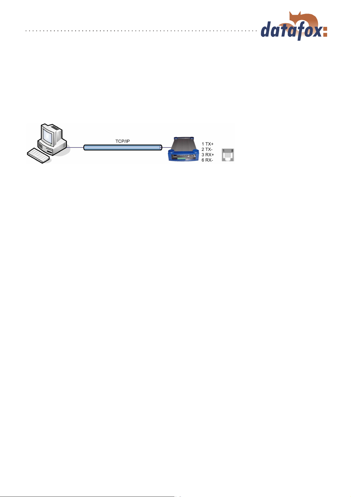
3.5.5.1 LAN
Analogous to the direct connection via RS232 a single device can be connected directly to the PC via
TCP/IP. In this case the device is connected to the PC with a CAT-5 network cable (in case of direct
connection with crossover; in case of connection via router,... with patch cable) via the RJ45 jack. Please
note that the RJ45 jack can also be the RS485 port at "‘HW V 1.4"’ (see figure 7 point 2). The device
must have the option TCP/IP.
Figure 33: Connection to the PC via TCP/IP
Version: 04.01.07.00 Page 44 www.datafox.de

Manual Datafox ZK-MasterIV
3.5.5.2 Transition from TCP/IP to RS232
In order to connect a single device via RS232 to a TCP/IP network a COM-server has to be used. The
COM-server serves as converter.
Figure 34: TCP/IP to RS232
The necessary settings of the COM-server will be explained using the W&T COM-server as example.
The COM-server can be configured easily via the Wutility.exe program.
1.) Open the W&T program
2.) Open "‘inventory"’ and then "‘scan local network"’
3.) Mac-address is displayed at the menu; click on it
4.) Adjust IP-address via "‘Configuration"’ and "‘Assign IP-Address"’
5.) Click on telnet (screen) button
6.) The telnet menu is shown
7.) Press key 3 (setup port 0) and then 2 (UART setup)
8.) Further settings see b elow
9.) Save setup and close program
10.) Hardware settings see manual of the COM-server
Version: 04.01.07.00 Page 45 www.datafox.de

Manual Datafox ZK-MasterIV
Figure 35: COM-Server configuration over telnet
3.5.5.3 Transition from TCP/IP to RS485 Bus
Up to 31 devices can be connected economically via a COM-server with RS485 bus. You can find details
about the structure of a RS485-network in the separate networking description. You can request it from
us or download it from our homepage. Please note that the bus number has to be set directly at the
terminal (see chapter 4.5.12).
The network structure is a bus. The bus cable is lo oped through from one device to the other. Branching
is not allowed. The PC can be connected at the beginning, the end or somewhere in the middle of the
network. The total length of the bus cable must not exceed 1000 m.
Figure 36: TCP/IP to RS485 Bus
Version: 04.01.07.00 Page 46 www.datafox.de

Manual Datafox ZK-MasterIV
3.5.5.4 WLAN
The ZK-MasterIV can be integrated into a WLAN with a WLAN router via TCP/IP. Please note that a
WLAN router is an external component and that you have to pay attention to the compatibility to the
present network topology. You have to set the IP-addresses in the system menu bios of the ZK-MasterIV
and the WLAN router in accordance with the network class of the present network.
Figure 37: Connection of a ZK-MasterIV via WLAN router to a WLAN network of a company
3.5.6 Communication via RS485
The RS4485 Datafox Network is based on Modbus. Modbus is a simple and safe bus system and is also
used in measurement technology.
RS485 is no standard communication of PCs, therefore you need a converter to set up this kind of network.
See chapter 3.5.1.3 for the connection and the wiring for a transition from RS232 (PC) to a RS485 net
and see chapter 3.5.5.3 for the transition from TCP/IP (PC) to a RS485 net.
Caution:
It is possible that the RS485 interface is available in the form of a RJ45 jack at
devices of HW V 1.4 . Check if the RJ45 jack is a RS485 interface before you
connect an external voltage source to PIN 7 = GND and 8 = 24 V DC.
Note:
All components for the RS485 - interlinking can be ordered with the devices. You
find the articles in the suitable price-lists or on inquiry.
Version: 04.01.07.00 Page 47 www.datafox.de

Manual Datafox ZK-MasterIV
The bus line connects the converter and 31 ZK-MasterIV at most in series. Branching is not allowed. The
converter can be connected to the bus line at any place. The maximum total length of a bus cable is 1000
m. The bus line should be laid in trunkings at the ceiling or the wall. In order to connect a ZK-MasterIV
the data line is wired to a Cat. 5 outlet and connected via a RJ45 patch cable or via outlets with terminal
strips via a stub line from the RS485 bus to the terminals. You can connect one Datafox-Bus per RS232
interface at the PC. You can install as many busses as you like also at different PCs. One communication
program per bus is active to operate the communication between the single devices and the central data
server. Because of potential differences a Datafox-Bus line should not be laid between different buildings.
This connection should be mainly realized via the PC network via glass fibre.
3.5.7 Active connection via TCP/IP
An active connection is supported from the firmware version 04.01.05.x on. This function is available for
the main communication TCP/IP, WLAN and GPRS (only from the GSM-module MC55 on)
The connection is always bidirectional full-Duplex. The communication is based on the Datafox protocol
of the MasterIV series.
3.5.7.1 Description
The concept for an active connection contains the realisation of an initialisation of the TCP/IP connection
between the device-software (firmware) and the DLL-software. The connection is always initialized by
the firmware. The link negotiation is done via appropriate commands with the DLL.
Note:
Note: For most providers a TCP/IP connection establishment "from the outside"
is not possible. Therefore the connection has to be established by the firmware.
Either the connection requests are blocked directly by the provider or the IP-address
established by the PC is not the real one of the device.
A connection establishment can be done in TCP/IP networks (also GPRS). The devices do not permit
several connections at the s ame time. Therefore no other connections must be established in order to
initialize the connection establishment.
In principle, a connection request of a Device to the DFComDLL is processed as follows:
The DLL receives a connection request on a listen socket. The connection administration checks, whether
a port object can be created. After creating a port object, the connection is established and remains for
further applications.
Version: 04.01.07.00 Page 48 www.datafox.de

Manual Datafox ZK-MasterIV
3.5.7.2 Configuration of an active connection
An active connection requires that the following parameters are set or configured in the ZK-MasterIV or
the application (DFComDLL.dll):
com.active (0 = deaktiviert, 1 = aktiviert) Switching on/off the active connection.
com.notify (0 = deaktiviert, 1 = aktiviert) Switching on/off the active data record message.
com.prio (0 = höchste, 65535 = niedrigste) Priority of the event messages in the queue.
com.host (0.0.0.0 bedeutet alle) Host to one connection should be produced.
com.port Port to one connection should be produced.
com.retry Number of the attempts for connection setup.
com.timeout Time out, after the set number has failed because of connection setup attempts.
com.repeat The time out if by successful message about present records these were not retrieved,
until a renewed message should be carried out.
com.alive Time out, when the terminal diminishes an existing communication channel (connection
quit) if no Kommunikations takes place. The DLL must send, if a communication channel should
not be diminished, cyclically a Ping to the ZK-MasterIV.
The bus address of the DLL (for call of DFCComOpenIV) is firmly given with 31. The number of
at the same time existing connections is delimited per DLL instance to 50 connections.
Here you have to pay attention to the following value margins and default values:
Description Name of the
system
Range of
values
Default value
variable
Activation com.active [0..1] 0
Active data record message com.notify [0..1] 1
Priority com.prio [0..65535] 0
Host com.host [IP-Adresse] 0.0.0.0
Port com.port [0..65535] 8000
Connection com.retry [0..65535] 3
Communication timeout com.timeout [0..4294967295] 900
Notification retry com.repeat [0..4294967295] 60
Connection check com.alive [0..4294967295] 0
Table 6: Parameters and default values for the configuration of an active connection
Version: 04.01.07.00 Page 49 www.datafox.de

Manual Datafox ZK-MasterIV
The parameters can be changed via the
dialogue active connection configuration
in the communication menu and be transmitted to the ZK-MasterIV. You may
find information about the single parameters in the table 6.
Grafik muss noch angepasst werden
Figure 38: Active connection configuration
The configuration of a ZK-MasterIV via
the DatafoxStudioIV with an active connection requires an active communication
port (selected port: see figure on the left)
from the device to the DLL. Set the alive
ping, the communication timeout and the
port according to your demands on the
configuration. A fterwards all functions
of the DatafoxStudioIV can b e used in
order to configure the device.
Figure 39: Setting the communication via the ZK-MasterIV
Version: 04.01.07.00 Page 50 www.datafox.de

Manual Datafox ZK-MasterIV
3.5.7.3 Device servicing via active connection
The following overview shows you the single procedures of the active connection and the possibilities for
the servicing of the terminals.
Figure 40:
Version: 04.01.07.00 Page 51 www.datafox.de

Manual Datafox ZK-MasterIV
Version: 04.01.07.00 Page 52 www.datafox.de

Manual Datafox ZK-MasterIV
3.5.8 WLAN
3.5.8.1 General information
There are two possibilities to configure the match port. Either via the TCP/IP with the DeviceInstaller
of LantronixR or via the RS232 using the tool WLANConfig and the DatafoxStudio (from version
04.01.06.xx on).
3.5.8.2 Terms and explanations
3.5.8.2.1 Infrastructure Mode
(Loose translation of an excerpt from the German version Wikipedia, the free encyclopaedia)
The Infrastructure mode is similar to the structure of the mobile communications network: A special base
station (Access Point) is used to coordinate the other network nodes (Clients). The base station sends
small data packets (so called Beacons) in adjustable intervals (ten times per second by default) to all
stations being in the footprint. The beacons contain among others the following information: Network
name ("Service Set identifier", SSID), List of supported transfer rates, Type of encryption.
This beacons ease the connection establishment, because the clients just have to know the network name
and optional some parameters for the encryption. The permanent sending of beacon-packets also allows
a control of the reception quality - also when no user data are s ent or received. The beacons are always
sent with the lowest transfer rate (1 MBit/s), the successful reception of the beacons does not guarantee
a steady connection to the network.
TM
3.5.8.2.2 Ad-hoc Mode
(Loose translation of an excerpt from the German version Wikipedia, the free encyclopaedia)
In the Ad-hoc mode (lat.: "created for this moment") no station is favoured; they all are on a par. Ad-hoc
networks can be established quickly and without great effort. But for a spontaneous networking of a few
terminals other techniques (Bluetooth, Infrared) are commonly used.
The preconditions for using the Ad-hoc mode are the same as f or the Infrastructure mode: All stations
use the same network name ("Service Set Identifier", SSID) and optionally also the same settings for the
encryption. Because there is no central instance for this operating mode and because no beacon-packets
are sent, a client cannot determine, whether there are other stations (using the same settings) within
reach, who is part of the network or how good the connection quality is. Therefore, the Ad-hoc mode is
suitable only for a small number of stations, that have to be close to each other because of the limited
reach of the transmitter. Otherwise, it is possible, that a station cannot communicate with the other
stations, because they simply do not receive a signal.
Forwarding data packets between the stations is not intended and not possible without further ado in
practice, because in the Ad-hoc mode no information are exchanged, that might give the single stations
an overview over the network. Gathering and exchanging these information is part of the upgrading of an
Ad-hoc network to a mobile Ad-hoc network: Software components on each stations collect data (e.g. for
visibility of other stations, connection quality etc.), exchange them among each other and make decisions
concerning the forwarding of the user data. The development in this field is not finished yet. By now
Version: 04.01.07.00 Page 53 www.datafox.de

Manual Datafox ZK-MasterIV
a long list of experimental protocols (OLSR, MIT RoofNet, B.A.T.M.A.N etc.) and several proposals
for standardisation (Hybrid Wireless Mesh Protocol, 802.11s) as well as some commercial solutions (e.g.
Adaptive Wireless Path Protocol from Cisco) were produced.
3.5.8.2.3 Frequencies and ports
Channel
Number
1 2,412 Europa, USA, Japan 8 2,447 Europa, USA, Japan
2 2,417 Europa, USA, Japan 9 2,452 Europa, USA, Japan
3 2,422 Europa, USA, Japan 10 2,457 Europa, USA, Japan
4 2,427 Europa, USA, Japan 11 2,462 Europa, USA, Japan
5 2,432 Europa, USA, Japan 12 2,467 Europa, Japan
6 2,437 Europa, USA, Japan 13 2,472 Europa, Japan
7 2,442 Europa, USA, Japan 14 2,484 Japan
Table 7: Frequencies and ports
3.5.8.2.4 Security and encryption
(Loose translation of an excerpt from the German version Wikipedia, the free encyclopaedia)
Part of the WLAN standard IEEE 802.11 is the Wired Equivalent Privacy (WEP), a security standard
containing the RC4 algorithm. The contained encryption, with a static key of a length of just 40 bits
(called 64 bits) or 104 bits (called 128 bits), sometimes also 232 bits (called 256 bits), does not guarantee,
that the WLAN is secured sufficiently. By collecting pairs of keys Known-Plaintext-Attacks may happen.
There are freely available programs, that are able to decrypt the password (a fast computer assumed),
sometimes even without a complete packet cycle. Furthermore, each user of the network can read along
the whole communication. The combination of RC4 and CRC is considered to be cryptographic insecure.
Frequency
(GHz)
Permit in Channel
Number
Frequency
(GHz)
Permit in
Therefore, technical complements were developed (e.g. WEPplus, Wi-Fi Protected Access (WPA) as
advance and subset of 802.11i, Fast Packet Keying, Extensible Authentication Protocol (EAP), Kerberos
or High Security Solution, that reduce the insecurity of WLAN more or less effective.
Child of the WEP is the new security standard 802.11i. It offers an increased security by using the TKIP
(Termporal Key Integrity Protocol) for WPA or the AES (Advanced Encryption Standard) for WPA2. At
the moment, it is regarded to be non-decipherable, as long as no trivial passwords are used, that can be
decrypted via a dictionary-attack. It is recommended to create the passwords with a password generator,
that contain special, numeric and alphabetical characters (upper and lower case) and have a minimum
length of 32 characters.
CCMP (= Counter Mode with Cipher Block Chaining Message Authentication Code Protocol) or also
Counter-Mode/CBC-Mac Protocol is , according to IEEE 802.11i, a cryptography algorithm. CCMP is
based on the Advanced Encryption Standard (AES) and uses a 128-bit-key with a 48-bit-initialisator for
answer query.
3.5.8.2.5 Authentification
(Loose translation of an excerpt from the German version Wikipedia, the free encyclopaedia)
Version: 04.01.07.00 Page 54 www.datafox.de

Manual Datafox ZK-MasterIV
Extensible authentication Protocol is a protocol for authenticating clients. It can access to the RADIUS
server for user administration. EAP is mainly used for large WLAN installations within WPA.
Encryption systems, that require, that both members know the keys before communicating (= s ymmetric
systems), are called Pre-Shared Key (PSK). An advantage of the PSK encryption is, that it can be
realized more easily between two known members than asymmetric encryption. The major disadvantage
of this system is, that the two members have to exchange the key in private before the communication
takes place. Therefore, the PSK system is not suitable for many applications in the internet (e.g. online
shopping), because there the prior exchange of a key is impossible or far too extensive. In such a case it
is easier to use the Public-Key system.
3.5.8.2.6 Passwords
(Loose translation of an excerpt from the German version Wikipedia, the free encyclopaedia)
Modern encryption system are technical advanced insofar as they often can only be decrypted via dictionary attacks (except from trying all possible keys = Brute-Force method). At both attacks the weak point
is the password (key), set by the user. In order to create a password, that is not less insecure than the
actual encryption (112 to 128-bit-key for current systems), theoretically a sequence of about 20 random
characters is necessary. If no random characters are used, considerable longer passwords are necessary in
order to guarantee the same security level.
The length of passwords, that can be used for encryption, is often limited by the software (e.g. using
AES passwords with more than 32 characters do not increase the security). Therefore, you should always
use combinations of characters, that consist of rare words or word orders, fantasy or foreign-language
words, initial letters of a sentence, numeric and/ or special characters or even combinations thereof. Its
components should be unforeseeable for an attacker, who is well-informed ab out the person and his/her
interests. As alternative you can use a password generator and fix the password in you memory or you
note it on a secret place.
A relatively secure password could be: 0aJ/4%(hGs$df"Y! (16 characters). The major problem of such
sequences using random characters is, that they are difficult to be kept in mind and therefore have to be
noted somewhere. A simpler alternative is, to use a rehearsed sentence and to change some characters,
e.g. "‘dIE bANANNE*3 durch 1/4 nIKOTIN"’ (32 characters). It is very important to work in enough
random characters. Suitable is the use of the initial letters of a sentence, e.g. "‘LS-Wbt7m/Ia1000tftY"’,
created with the initial letters of the sentence "‘Little Snow-White beyond the 7 mountains/ Is a 1000
times fairer than You"’.
Although the use of special characters can increase the security, because the password becomes more
complicated, you should use them carefully, if there is the possibility, that the password has to be used in
foreign countries: It might be possible, that some special characters do not exist on foreign keyboards.
3.5.8.3 BIOS dialogue DatafoxStudioIV
In the BIOS dialogue of the Datafox Studio (< Communication => Dev ice configuration BIOS >) you
can make the same settings as directly on the terminal (except the restriction at TCP/IP Set default and
Factory default WLAN, which is possible only at the terminal). You could compare the BIOS menu with
a remote maintenance tool, but changing the settings is accessible only via RS232.
The setting of WLAN parameters is going to be available from version 04.01.06.xx in the Datafox Studio.
Version: 04.01.07.00 Page 55 www.datafox.de

Manual Datafox ZK-MasterIV
3.5.8.4 Dependencies
Because of the different methods for parameterisation, certain dependencies of several parameters arise.
Figure 41: Dependencies
3.5.8.5 WLAN configuration via the Lantronix tool
You may find the device installerTMof LantronixR on the enclosed Datafox product DVD under
DVD:
Datafox-Optionen ( eingebaute Module )wLAN, Matchport.
With the help of this tool the COM servers Xport and MatchPort of the Datafox devices can be configured.
The device installer accesses to the COM server via TCP/IP, the Datafox terminals via RS232. If a COM
server is not available, because it is adjusted that much, so that the device installer is unable to access,
it is possible to reset the COM server to the default values via the BIOS menu of the terminal.
Version: 04.01.07.00 Page 56 www.datafox.de

Manual Datafox ZK-MasterIV
3.5.8.6 WLAN configuration via the DatafoxStudioIV
3.5.8.6.1 General
The program WLANConfig can set the TCP/IP and the WLAN settings of the MatchPort via RS232.
These settings can be saved as a file and the data of this file can be transmitted to the device. The dependencies of the single parameters among each other are p ermitted or locked by the program automatically.
Four dialogues are provided for working with the program.
WLAN settings (main dialogue)
Selection of the serial interface (COM settings)
Selection of the configuration file (Select I NI-File)
TCP/IP settings (Terminal TCP/IP settings)
3.5.8.6.2 Selection of the serial interface
Figure 42: Selection of the serial interface
Via this dialogue you can select the interface of the PC, to which the MasterIV
terminal is connected. Usually a baud
rate of 38400baud is set, which has to correspond to that one of the terminal. You
start the dialogue by pressing the button
COM settings.
Version: 04.01.07.00 Page 57 www.datafox.de

Manual Datafox ZK-MasterIV
3.5.8.6.3 Selection of the configuration file
Via the button Select INI-File the dialogue is started. Here you can create new
files or select a file, where data are logged
on. On the INI file all settings of the
TCP/IP and the WLAN are logged.
Figure 43: Selection of the configuration file
Version: 04.01.07.00 Page 58 www.datafox.de

Manual Datafox ZK-MasterIV
3.5.8.6.4 TCP/IP settings
Via the button Terminal TCP/IP Settings the dialogue is started. The current firmware version of the MatchPort
and the MAC-address are displayed. You
can edit the other parameters, which are
equal to those of the BIOS dialogue of
the terminal and of the Datafox Studio.
Figure 44: Selection of the configuration file
3.5.8.6.5 WLAN settings
The WLAN settings allow the editing of values, that were read out of the terminal and loaded inon a
INI file or entered manually. It is very important, that the key cannot be read out of the terminal. It
also cannot be re-recorded, if it was not entered. If the key i s available in the INI file, a group of *
characters is displayed on the key-edit fields after loading the data. It is also transmitted to the device
then. In order to use WLAN you have to set WLAN Enable. This parameter can also be set by the device
installer of Lantronix. If you want to configure several devices via WLANConfig, you have to note, that
the IP-address of the devices has also to be set.
Caution:
After transmitting the parameters the device has to be set from RS232 to TCP/IP,
so that the MatchPort is activated. Only then it is available in the network.
Version: 04.01.07.00 Page 59 www.datafox.de

Manual Datafox ZK-MasterIV
Via Read WLAN Config the data are
loaded from the device to the program.
Via Write WLAN Config the data are
loaded from the program into the device.
Via Read INI file the data are loaded
from the selected file into the program.
Via Write INI file the data are written
from the program in the file.
Figure 45: Selection of the configuration file
Version: 04.01.07.00 Page 60 www.datafox.de

Manual Datafox ZK-MasterIV
3.6 Access control II with TS TMR33 modules
The following hardware is available to construct an access control with TS TMR33 modules. The different options can be combined with each other according to the hardware requirements of the single devices.
ZK-MasterIV
Because the ZK-MasterIV is only used for the access control, door and remote
monitoring, you can supervise up to 16 doors with one device and control 18
doors at most.
Türmodul (TS TMR33-TM)
72 x 72 x 40 mm
The door module is offered as pure electronic component e.g. to build it in a
patress box, or in a housing for surface mounting with alarm control panel.
Reader (TS TMR33-L)
80 x 80 x 25 mm
The reader can be ordered separately to connect it directly to a PC or another
access check. A connecting diagram and a description of the commands for the
activation are included.
Module set = reader + door opening function (TS TMR33-LTM))
80 x 80 x 25 mm
The module set can be ordered separately to connect it directly to a PC or another
access check. A connecting diagram and a description of the commands for the
activation are included.
3.6.1 Set-up
In the following chapters different possibilities to set the device up are ex plained. The ZK-MasterIV is
used as reference device.
Version: 04.01.07.00 Page 61 www.datafox.de

Manual Datafox ZK-MasterIV
3.6.1.1 A door without a separate reader
The time recording terminal is access scanner, access master and do or-opener at the same time. This
solution should only be used in protected places so that the door opening relay cannot be manipulated.
RS232 / 485
TCP/IP
GSM/GPRS
wLAN
Relay to the door opener
Input for door supervision
3.6.1.2 A door with a separate reader
The ZK-MasterIV is installed in a protected area inside a building and the reader is installed outside.
The terminal is access master and door-opener at the same time. The door opening relay is in the ZKMasterIV and thus in the protected area. The access identification captured by the reader is transmitted
to the ZK-MasterIV and analysed by it. If the access is permitted, the door is opened via the relay in the
ZK-MasterIV.
RS232 / 485
TCP/IP
GSM/GPRS
wLAN
RS485-wire, 1000 m at most
Relay to the door opener
Input for door supervision
Reader Type: 106020
Set reader
on RS485
via DIP-switch
This version is used frequently and can be installed easily and economically as shown in the figure above.
Version: 04.01.07.00 Page 62 www.datafox.de

Manual Datafox ZK-MasterIV
3.6.1.3 Several external doors via RS485 bus
Here a door module has to be used so that the door opening relay is in the protected area.
RS232 / 485
TCP/IP
GSM/GPRS
wLAN
RS485 - Bus
1000 m at most
Door module
type: 106011
set on
RS485 and bus
number via
DIP-switch
Pushbutton to
open
doors without
door handle
from inside,
if necessary.
RS232 connection, 15 m at most
Relay
Door supervision
Reader type: 106020
set reader
on RS485
via DIP-switch
Relay
Door supervision
The do or mo dule permanently calls up the reader. If a transponder is read the information is transmitted from the reader to the door module. The ZK-MasterIV permanently polls to the door module. If
a booking is available, it is collected immediately. If the access is permitted, the ZK-MasterIV sends a
command to the door module to open the door.
Note:
The relay in the ZK-MasterIV can be used here as well. See chapter 3.1, that means
the terminal can replace the first door module. In order to use the appropriate
reader in the RS485 bus, it has to be set on RS485 via the DIP switches at the
backside of the reader.
Version: 04.01.07.00 Page 63 www.datafox.de

Manual Datafox ZK-MasterIV
3.6.1.4 Several internal doors via RS485 bus
The combined reader + door-module is used here. The door opening relay is included in the combined
module. Watch out, this assembly must not be used at outdoor locations because then the relay is not in
a protected area.
RS232 / 485
TCP/IP
GSM/GPRS
wLAN
RS485 - Bus
1000 m at most
Reader type:
106020
set reader
on RS485
via DIP-switch
Relay
Door supervision
Relay
Door supervision
Pushbutton to
open
doors without
door handle
from inside,
if necessary.
The ZK-MasterIV permanently polls to the door module. If a booking is available, it is collected immediately. If the access is permitted, the ZK-MasterIV sends a command to the door module to open the door.
Note:
The relay in the ZK-MasterIV can be used here as well. See chapter 3.1, that means
the terminal can replace the first door module. In order to use the appropriate
reader in the RS485 bus, it has to be set on RS485 via the DIP switches at the
backside of the reader.
Version: 04.01.07.00 Page 64 www.datafox.de

Manual Datafox ZK-MasterIV
3.6.1.5 Mantrap function with RS485 bus
The combined reader + door-module and the reader-module is used here.
RS232 / 485
TCP/IP
GSM/GPRS
wLAN
RS485 - Bus
1000 m at most
Reader type:
106030
set reader
on RS485
via DIP-switch
RS232 connection, 15 m at most
Relay
Door supervision
Reader type: 106020
set reader
on RS485
via DIP-switch
Relay
Door supervision
The ZK-MasterIV permanently polls to the door module. If a booking is available, it is collected immediately. If the access is permitted, the ZK-MasterIV sends a command to the door module to open the door.
Note:
The relay in the ZK-MasterIV can be used here as well. See chapter 3.1, that means
the terminal can replace the first door module. In order to use the appropriate
reader in the RS485 bus, it has to be set on RS485 via the DIP switches at the
backside of the reader.
Version: 04.01.07.00 Page 65 www.datafox.de

Manual Datafox ZK-MasterIV
3.6.2 Connection
The following figure shows the possibilities for connecting the TMR33 devices to a ZK-MasterIV for the access control. The TMR33 devices have to be set depending on the interface that is used (RS232 or RS485).
Figure 46: Connection of the access control II
The DIP switches 1 - 5 are for the bus configuration. Via them the bus number of the device is set. The
DIP switch 1 in position "‘ON"’ and 2 - 5 in position "‘OFF"’ stand for bus no. "‘1"’. The DIP switches
1 and 2 in position "‘ON"’ and 3 - 5 in position "‘OFF"’ stand for bus no. "‘3"’.
Version: 04.01.07.00 Page 66 www.datafox.de

Manual Datafox ZK-MasterIV
Caution:
The installation and connection of the TMR33 module may only be carried out by
a p erson qualified in this field. Avoid switching the connecting terminal (reverse
polarity).
From this arise different possible combinations. The following figures show examples for the connection
wiring.
3.6.2.1 Wiring
In most cases a shielded twisted pair cable is used as transmission medium for the assembling of a RS485
bus. It should be a twisted pair cable because that way the voltages induced by an electromagnetic field
work opposite and thus offset each other.
In accordance with the specifications (TIA-EIA-485-A) the maximum cable length depends on the transmission rate.
length of segment [m] 100 200 400 1000 1200
data rate [kBit/s] 12000 1500 500 187,5 9,6
Table 8: Cable length dependent from the data rate
Our recommendations for a data cable are the following types of cables: Li-YcY 2x2x0,5 mm2, J-2YY
2x2x0,5 mm2oder J-Y(ST)Y 2x2x0,5 mm2(Cat5 shielded).
Caution:
When erecting an access control system, a calculation of the maximum cable length,
the necessary cable cross-section and voltage supply has to be done in any case. See
chapter 3.6.2.2 for further hints.
Version: 04.01.07.00 Page 67 www.datafox.de

Manual Datafox ZK-MasterIV
Example: Wiring for a door
An external access reader TS TMR33-L is connected directly to the terminal. The door opening is controlled via the relay integrated in the terminal. Further functions, e.g. supervision of the door (open or
closed), can b e realized via the digital inputs of the ZK-MasterIV.
Figure 47: Wiring for a door
In this case the reader table (access control list) has to be configured as follows:
ID ZM TM RefLocation RefAction PinGeneral
1 1 320 0 1 0
2 1 000 0 1 0
Table 9: Reader table
ID = 1 identifies the data record for the ZK-MasterIV, that always gets the value 320 in the column TM
(Türmodul/ door module). ID = 2 identifies the external reader (TS TMR33-L), that is connected to the
ZK-MasterIV via RS485. The type of connection (RS485) is marked by the zero at this position 000 in
the column TM.
Version: 04.01.07.00 Page 68 www.datafox.de

Manual Datafox ZK-MasterIV
Example: Wiring of a mantrap
A door is controlled via an internal door module with integrated reader TMR33-TMR and an external access reader TMR33-TR as mantrap In this case the internal door module is connected to the ZK-MasterIV
via a RS485 bus. The external access reader is connected to the internal door module with a R S232 stub.
The door opening is controlled via the relay integrated in the door module TMR33-TMR. In this case the
door module with the relay is in the secure area and the external access reader without a relay is in the
insecure area.
Figure 48: Wiring of a mantrap
Note:
• Connection for electricity supply via p ower supply unit or bell transformer.
Please note the hints for the calculation of the cable cross-section and the
cable length.
• Install the door-opener in the protected area when using it for exterior doors.
• At closed door contact aprox. 15 mA are used up at 12 V = 0,18 Watt. This
means a consumption of aprox. 1,6 kWh per year.
Version: 04.01.07.00 Page 69 www.datafox.de

Manual Datafox ZK-MasterIV
Example: Controlling the door-opener only via the ZK-II You can control the door-opener directly via
the access control-II (ZK-II). Please note that the door-opener has to work in a voltage range from 8 to
12 V DC and must not exceed a power consumption of 100 mA.
Figure 49: Controlling the door-opener via ZK-II
Example: Controlling the door-opener via the ZK-II and a push-button It is possible to additionally
connect a push-button for controlling the door-opener.
Figure 50: Controlling the door-opener via the ZK-II and push-button
Version: 04.01.07.00 Page 70 www.datafox.de

Manual Datafox ZK-MasterIV
Example: Controlling the door-opener via the ZK-II, relay and push-button
You want to control the door-opener directly via the access c ontrol-II. You want to open the door without
transponder via a push-button in a lobby with a view of the entrance area. Additionally, this push-button
circuit should only be active at certain times. This scenario can be portrayed as follows:
Figure 51: Controlling the door-opener via the ZK-II, the relay and a push-button
Initially, we use an external voltage source for the supply of the door-opener. It is controlled via the
relay of the TS TMR33-TM, connection 1 and 3 of the strip terminal P16. The NC contact of the relay
is bridged with the push-button. The activation of this push-button circuit is realized via an additional
relay (TS TMR33-TM). You can configure the period of time of the activation at the access control lists
in the ZK-II. For this you have to include the additional TS TMR33-TM module in the reader table. In
the action table you set which output (relay) is switched on which module of the reader table. Set the
elapse-value on 0. You define via the reference on a time model (RefTime) from when the relay switches
(push-button circuit activated) and when the relay drops out again.
Version: 04.01.07.00 Page 71 www.datafox.de

Manual Datafox ZK-MasterIV
Figure 52: Wiring scheme
Version: 04.01.07.00 Page 72 www.datafox.de

Manual Datafox ZK-MasterIV
3.6.2.2 Calculation instructions
When using Datafox access readers or door modules, the necessary cable cross-section has to be calculated
before setting up a RS485 network for the access control. The voltage drop in the whole bus must not
be higher than 4 V. Please note that if you use a Datafox device power supply unit as voltage source, 16
modules at most (8 in the RS485 bus and 8 via R S232 stub line) can be fed.
Maximum power consumption of the single modules:
TS-TMR33-TR 56,5 mA
TS-TMR33-TM 156,0 mA
TS-TMR33-TMR 180,0 mA
The result of it is a permissible maximum power consumption per Datafox device power supply unit of
(8 x 180,0 mA + 8 x 56,5 mA) 1,9 ampere. I n order to assure this, you can calculate the necessary crosssection for a given cable length or the permissible maximum cable length for a given cable cross-section.
Caution:
Before a setting up and commissioning of a ZK-network, in any case the calculation
has to be done by a person qualified in this field.
The cable cross-section is calculated as follows:
2
I
U
l
v
q = Cable cross-section in mm
q
κ
2
I = Current in A
l = Cable length in m
κ = Conductivity (kappa) for Cu-conductor = 56
m
Ωmm
2
Uv = Voltage drop 4 V at most
Thus the developed equation for calculating the maximum cable length for a given cable
cross-section is:
q
κ
U
l
2
v
I
Version: 04.01.07.00 Page 73 www.datafox.de

Manual Datafox ZK-MasterIV
3.6.2.3 Topologie
If a bus topology is used when setting up the network, you have to calculate the cable cross-section for each
bus segment with regard to the maximum power consumption of the respective segment (see figure 53).
At a star cabling the cable cross-section for each cable has to be calculated with regard to of the power
consumption of the respective module.
Because this document only deals with the voltage supply of an access control
system, the depiction of the RS485 data bus is abandoned in the figures. The
voltage supply is simply depicted as one line. Additionally, the cable length that
has to be calculated is marked by a broken line.
3.6.2.4 Examples
3.6.2.4.1 Bus topology
We take as a basis that the longest distance from the voltage source to the last module is 65 m.
Note:
Figure 53: Bus topology
In order to assure a high safeguarding and to keep the calculation simple, you can take the following
steps. Calculate the power consumption of all modules connected to a voltage source (max. 16 modules)
and take the longest distance from the voltage source to the las t module. If the result of this simplified
method of calculation for the cable cross-section is a value higher than 1, 5 mm2, you have to use additional power supply units and recalculate the system. By this additional power supply unit you can
compensate the voltage drop at a smaller cable cross-section by a shorter cable length (two sub-networks
with regard to the voltage supply not with regard to the RS485 data bus). The calculation of the total
power consumption for the example in figure 53 is as follows.
I
4
56, 5 mA
2
156, 0 mA
5
180, 0 mA
1.438 mA
1, 438 A
Now we put the values in the equation and get the necessary cable cross-section:
Version: 04.01.07.00 Page 74 www.datafox.de

Manual Datafox ZK-MasterIV
21, 438A65m
q
56
Ωmm
m
q0, 83mm
21, 438A65mVmm
4V
2
2
56m4VA
2
If we take as a basis that the bus has a maximum length of 200 m, the result of the calculation will be a
cable cross-section of 2, 6 mm2. That means we would need an additional power supply unit.
3.6.2.4.2 Star topology
In this example the maximum cable length for each cable is calculated separately for a given cable crosssection. We take a cable cross-section of 0, 75mm2as a basis. The length of each cable has to be calculated
separately.
Figure 54: Star topology
Version: 04.01.07.00 Page 75 www.datafox.de

Manual Datafox ZK-MasterIV
cable 1:
I1x180, 0mA1x56, 5mA
I236, 5mA
I0, 2365A
The result for the maximum cable length for cable 1 is:
2
20, 2365A
l
0, 75mm
56
Ωmm
m
4V
2
0, 75mm
20, 2365AVmm
2
56m4VA
l355, 2m
cable 2:
I1x156, 0mA1x56, 5mA
I212, 5mA
I0, 2125A
The result for the maximum cable length for cable 2 is:
2
20, 2125A
l
0, 75mm
56
Ωmm
m
4V
2
0, 75mm
20, 2125AVmm
2
56m4VA
l395, 3m
cable 3:
I180, 0mA
I0, 18A
2
2
The result for the maximum cable length for cable 3 is:
2
20, 18A
l
0, 75mm
56
Ωmm
m
4V
2
0, 75mm
2
56m4VA
20, 18AVmm
2
l466, 7m
Note:
The total power consumption has to be calculated for each cable.
3.6.3 Configuration
The basis of the access control II are tables. They store all information about the hardware configuration
of the access control system, access right of the staff, periods of time (activation, blocking times, holidays,...). There is the following connection between the tables:
The tables are created as text files. For an easier administration you can add comments within the files.
Version: 04.01.07.00 Page 76 www.datafox.de

Manual Datafox ZK-MasterIV
1
6
Figure 55: Data structure of the access control II
7
3
2
5
4
When adding comments you have to notice that in a comment line no field values can be given and that
the comment line has to start with a semicolon.
A Reader.txt (Reader table) could look as follows:
; Reader list for the test access control system
; ID ZM TM RefLocation RefAction PinGeneral
1 1 320 1 1 0
2 1 010 1 1 0
Please gather a close description of the table structure, indication of the data types and field length from
the following tables.
Version: 04.01.07.00 Page 77 www.datafox.de

Manual Datafox ZK-MasterIV
Alias Data type
Length
ID Number
(int)
ZM Number
(int)
TM Number
(int)
RefLocation Number
(int)
RefAction Number
(int)
PinGeneral Number
(int)
Table 10: Reader table (list of all devices installed in the system - master and door modules)
Alias Data type
ID String
(ASCII)
Group Number
(int)
Pin Number
(int)
Menace Number
(int)
ActiveStart String
(Date)
ActiveEnd String
(Date)
ActiveGeneral Number
(int)
4 Unique Key (W ert0) of the Reader table.
4 It has in our example number 1. If there are several
3 Contains two information in one number. Both figures on
4 Indicates which room is supervised by the reader.
4 Indicates which action is worked through after a successful
8 Can contain a numerical sequence via which a person
Length
20 Contains the card no. which is read at the TMR33 device
4 Assigns the card to an authority group.
8 Activates a PIN query if not equal 0. Please note that a
4 Activates (if not equal 0) a "‘menace-PIN"’ that can be
10 The tag entered here indicates the beginning of validity of
10 The tag entered here indicates the end of validity of the
1 Activates or deactivates this card record.
Description
PZE-MasterIV in an access system, they can be depicted in
one table connection and it is not necessary to have a
separate string for each PZE-MasterIV.
the left (010)indicate the bus number of the door module,
the figure on the right (010) contains information about the
type of connection. A 0 means a connection via RS485, a 1
stands for a connection via RS232 as stub.
check.
without a card gets access.
Description
or terminal. A card can occur several times (is assigned to
several authority groups).
PIN must not start with a zero. 0815 would be invalid.
added to the PIN. If entered, the system sends a data
record that can be analysed by software developed for this
purpose and sets off the alarm.
the card.
card (e.g. 2007-07-12 = yy yy-mm-dd).
0 = card blocked
1 = card active
2= virtual card (use only via DLL)
3 = access only by entering the PIN
9 = general authority (no PIN query)
Table 11: Identification table (list of all cards known by the s ystem))
Version: 04.01.07.00 Page 78 www.datafox.de

Manual Datafox ZK-MasterIV
Alias Data type
Length
ID Number
(int)
RefGroup Number
(int)
RefTime Number
(int)
Number
RefTimeNoPin
Table 12: Location table (defines which card groups get access to which room at which time)
Alias Data type
ID Number
Weekdays Number
TimeStart String
TimeEnd String
(int)
(int)
(int)
(Time)
(Time)
4 ID of the room. All other tables refer to this data line via
4 Reference to the identification table. Labels the access
4 The time model in which authorized persons get access. (0
4 The time model to which an additional PIN does not need
Length
4 ID of the time model. All other tables refer to this data
7 Indicates the weekdays on which the following period of
5 The start time for the period of time. (form: 24h HH:MM)
5 The ending time for the period of time.
Description
this number, if necessary.
authorized group. All cards of this group have access to
this room.
= not used)
to be entered (at peak times etc.).
Description
line via this number, if necessary.
time should be applied to (form: 7 digits at most 1-7 e.g.
134567 = Monday, Wednesday till Sunday)
Table 13: Time table (grouping of single time zones (weekday from to) as a time mo del number)
Alias Data type
Length
Day String
(Date)
RefGroup Number
(int)
RefTime Number
(int)
Table 14: Holiday table (setting of blocking days like holidays or company holidays)
Alias Data type
RefReader Number
(int)
PortIn Number
(int)
RefAction Number
(int)
RefTime Number
(int)
10 Date of the blocking day. (form: YYYY-MM-DD)
4 Indicates the authorization group to which the blocking
4 Indicates the assigned time model. (0 = not used) During
Length
4 Module (door module or master) on which is the digital
1 Number of the digital input on the module.
4 Reference to the action that should be carried out (e.g.
4 The time model which indicates when the digital input is
Description
day is applied.
A zero defines a global validity for all groups.
this time access is granted. Thus, also "‘half holidays"’ like
New Year’s Eve can be realized.
Description
input.
switch relay).
checked. (0 = not used)
Table 15: Event table (assigning an action to a signal at the digital input)
Version: 04.01.07.00 Page 79 www.datafox.de

Manual Datafox ZK-MasterIV
Alias Data type
Length
ID Number
(int)
RefReader Number
(int)
PortOut Number
(int)
Elapse Number
(int)
RefTime Number
(int)
Table 16: Action table (list of all workable actions in the access control system; an action group - all
actions with the same action number - can switch several relays)
3.6.4 An example for a ZK system
On the basis of an example, it is demonstrated how an access control system is structured and configured.
The system consists of a RS485 bus via which a ZK-MasterIV communicates with a TS TMR33-TM and
a TS TMR33-LTM. The TS TMR33-TM additionally communicates with a TS TMR33-L via a RS232
stub line.
4 Action number, it can occur several times because of
4 Module (door module or master) on which an
1 Indicates the number of the output on the module.
3 The duration of the switching of the relay (0 =
4 The time model indicates when the output may be
Description
several actions that have to be worked through.
output(relay) is switched.
permanently). Unit 200 ms
switched. (0 = not used)
Door 1 is controlled via the TS TMR33-TM. The cards of the access authorized persons are read at the
TS TMR 33-L and analysed by the ZK-MasterIV.If a person is authorized, the TS TMR33-TM receives
a signal from the ZK-MasterIV and switches the open-collector for a given period of time in order to
open door 1. Because the TS TMR 33-L, which is an insecure are, is connected via a RS232 stub line,
manipulation of the s ystem can be ruled out.
Door 2 is controlled via the TS TMR33-LTM. The cards are read at this module and the data is transmitted to the ZK-MasterIV. I n case of access authorization the TS TMR33-LTM receives a signal for
switching the open-collector to which the door opener is connected.
Version: 04.01.07.00 Page 80 www.datafox.de

Manual Datafox ZK-MasterIV
Raum 1
Raum 2
Figure 56: Schematic depiction of an example system
Version: 04.01.07.00 Page 81 www.datafox.de

Manual Datafox ZK-MasterIV
The power supply for the ZK-MasterIV and the
access modules (TS TMR33) is established via the
red wire (12 V DC) and the blue wire (GND). Note
the information in chapter 3.2.1. The RS485 bus
is connected via the yellow wire (data line A =
+) and the grey wire (data line B = -). The 3 A
power supply unit is connected to the cabling v ia
an additional distribution box.
zum
TS-TMR33-LTM
RS232 an PC
Figure 57: Connection of the ZK-MasterIV
vom ZK-MasterIV
The bus no. is set on 0 via the DIP switch on the
door module with a reader (TS TMR33-LTM); the
11
zum
TS-TMR33-TM
P16
DIP switches 1 to 5 have to be at OFF. The DIP
switch 7 always has to be at OFF. The module is
not the last module in the RS485 bus. Therefore,
the DIP switch 8 has to be at OFF. The power
supply is established via PIN 10 (GND) and 11 (8
1
- 14 V DC) of the edge connector P16. The RS485
data channel A (+) is connected via PIN 8 and the
data channel B (-) via PIN 9.
Figure 58: Connection and configuration of the TS TMR33-LTM for RS485
In this example, the door opener is connected via PIN 6 (open-collector -) and PIN 7 (open-collector
+). The power is provided by the module. An additional voltage source is not necessary. However, you
have to observe that the door opener has to work within a voltage range of 8 to 12 V DC and that the
current consumption has not to exceed 100 mA. Otherwise , the door opener can also be switched via the
relay. In that case, a voltage/ switching current of 42 V AC/0,5 A or 60 V DC/0,3 A at most is permissible.
Version: 04.01.07.00 Page 82 www.datafox.de

Manual Datafox ZK-MasterIV
zum
TS-TMR33-L
The bus no. is set on 1 via the DIP switch on the
door module without a reader (TS TMR33-TM);
the DIP switch 1 has to be at ON, the DIP s witches
2 to 5 have to be at OFF. The DIP switch 7 always
vom
TS-TMR33-LTM
11
1
has to be at OFF. Because the module is the last
module in the RS485 bus, the bus with the DIP
switch 8 has to be at ON. The power supply and
the RS485 bus of the TS-TMR33-LTM is connected
P16
P17
analogous to figure 58. The power supply for the
external reader is established via PIN 10 and 11 of
1
11
the edge connector P16.
Figure 59: TS-TMR33-TM-RS485
RxD (grey) is connected via PIN 2 of the edge connector P17 in figure ... and TxD (yellow) is connected
to PIN 3 of the RS232 stub line.
vom
TS-TMR33-TM
The communication with the reader (TS-TMR33L) via a RS232 stub line is configured with the DIP
switch 6 at ON. No bus number has to b e set for
the reader. The Dip switches 1 -5 are at OFF. The
DIP switch 7 always has to be at OFF. The DIP
switch 8 is also at OFF because no timing has to
be turned on. The power supply of the module is
11
1
established via PIN 10 and 11 of the edge connector
P16. The RS485 data channel A is connected via
P16
1
P17
11
PIN 3 and the data channel B via PIN 2 of the
edge connector P17.
Figure 60: TS-TMR33-L-RS232-Stich
After setting up and wiring the system, the software configuration has to be done. All tables are mandatory. However, the tables holiday and event can be empty. The tables are displayed in the form of text
files. You also can log comments within the text files f or an easier maintenance of the system. You only
have to start a comment line with a semicolon in the first column. They must not be configuration data
within this comment line.
Version: 04.01.07.00 Page 83 www.datafox.de

Manual Datafox ZK-MasterIV
The Reader.txt (Reader table) has the following content:
; Reader list for the example access control system
; ID ZM TM RefLocation RefAction PinGeneral
1 1 320 0 0 0
2 1 000 1 1 0
3 1 010 2 0 0
4 1 011 2 2 0
The data record with the ID 1 stands for the ZK-MasterIV and receives number 1 as access master (ZM
- Zutrittsmaster). The access master always receives the number 320 as TM value, that means it always
receives the bus number 32. Because the ZK-MasterIV is not necessary for controlling a relay or door
opener, you can enter 0 in the Location table for the reference to a data record. The same applies to the
reference to the Action or as PinGeneral.
The data record with the ID 2 stands for the TS TMR33-LTM and is managed via the access master
(ZM) 1. The module receives the number 000 as TM value; both numbers on the left stand for the bus
no. 0 and the number on the right 0 marks the communication via RS485. At this place only 0 or 1 are
permitted. This module is assigned to the room with the location-ID (RefLocation) 1. If an access is
authorized, the action (RefAction) 1 shall be carried out. A PIN for an access without card (PinGeneral)
is not used; therefore, the value at this place is 0.
The data record with the ID 3 stands for the TS TMR33-TM and is managed via the ZM 1. The module
receives the number 010 as TM value. This value corresponds to the bus no. 1 with a communication
via RS485. The module is assigned to the room with the location-ID (RefLocation) 1. Because the door
module has no reader, it cannot set off an action in this example. As a note: it would be possible to set
off an action via the digital or analogous inputs of the door module. It is also not possible to enter a PIN,
thus, PinGeneral = 0.
The data record with the ID 4 stands for the TS TMR33-L and is also managed via the ZM 1. The
module receives the number 011 as TM value. This value corresponds to the connection to the module
with the bus no. 1 via RS232 via a stub line (data record 3). This module is assigned to the room
with the location-ID (RefLocation) 2. If an access is authorized, the action (RefAction) 2 shall be carried out. A PIN for an access without card (PinGeneral) is not used; therefore, the value at this place is 0.
The Identification.txt (Identification table) has the following content:
; Identification list for the example access control system
; ID Group Pin Menace ActiveStart ActiveEnd ActiveGeneral
1111 1 1111 511 2005-01-01 2008-01-01 1
2222 2 2222 522 2005-01-01 2008-01-01 1
You can adjust the ID or the PIN and the menace code to your requirements, dependent on the card
number you use. The time domain for ActiveStart and ActiveEnd can be set as well. If you do not have
modules with a keyboard, you can also set the PIN and menace code on 0.
Version: 04.01.07.00 Page 84 www.datafox.de

Manual Datafox ZK-MasterIV
The Location.txt (Location table) has the following content:
; Location list for the example access control system
; ID RefGroup R efTime RefTimeNoPin
1 1 3 3
1 2 3 3
2 1 1 0
The first data record sets that the person group 1 gets access to room 1 for the time model 3 without
needing to enter the additional PIN within the time model 3, because in this example the TS TMR33-L
and the TS TMR33-TM has no keyboard. The second data record defines the same for the person group
2. The third data record sets, that only the person group 1 gets access to room 2 within the time model
1 and additionally has to enter the PIN defined in the Identification.
The Time.txt (Time table) has the following content:
; Time list for the example access control system
; ID Weekdays TimeStart TimeEnd
1 12345 07:00 13:00
2 12345 13:01 18:59
3 12345 07:00 18:59
In the time table the different time models are defined.
The Action.txt (Time table) has the following content:
; Action list for the example access control system
; ID RefRead PortOut Elapse RefTime
1 1 1 25 0
1 2 2 25 0
2 3 1 25 0
2 3 2 25 0
The first data record sets that the first internal relay (PortOut = 1) of the ZK-MasterIV (RefRead 1 =
reference to the first data record of the reader table) is switched for the duration of 5 seconds. If you set
Elapse on = you have to give a time model in which you define how long the relay s hould be switched.
Otherwise, the switched relay permanently stays in this state. The second data record sets that the
open-collector (PortOut = 2) is switched on the TS TMR33-LTM (reference to the second data record of
the reader table) f or the duration of 5 seconds. You can now deduce data record 4 and 5.
The tables Holiday and Event are not necessary for this example. With regard to the configuration of the
holiday table it has to be mentioned that at first you set a holiday in the format YYY-MM-DD. Next, you
set the group for which this arrangement should be valid. I f several groups are concerned, simply display
the data record with the same date several times and change the group ID. In the third column of each data
record you can additionally set a time model. By this way you ca n define half-holidays like Christmas Eve.
The data record 2006-12-24 1 1 in the holiday table with the time model 1 12345 07:00 13:00 means that
on 24 Dec 2006 the person group 1 only gets access from 7 am to 1 pm (13:00).
With regard to the event table, the following things have to be mentioned: at first, you have to set the
Version: 04.01.07.00 Page 85 www.datafox.de

Manual Datafox ZK-MasterIV
module or the access master with a reference to the reader table on which the digital input is to be
supervised. The second value gives the number of the digital input. The third value is a reference to
the action table; this action is carried out if the level of the digital input changes. The forth and last
value is a reference to the time table for setting the time model which is valid for the execution of the action.
Even if you do not need the holiday and event table, they have to be generated as *.txt files (empty) and
be transmitted to the device together with the other files.
If you have paid attention to the construction and configuration instructions and their hints, you can
transmit the lists (tables or text files) to the ZK-MasterIV with a standard setup for the access control
and test them.
3.7 Timing of the digital exits for the MasterIV device series
It is possible to time the digital outputs of the MasterIV device series via tables. Thus, for example a
turn down of the heating system at nigh, a buzzer control and much more can be realized.
Caution:
In order to use the timing of the digital exits, the firmware version 04.01.01.17 (or
higher) has to be installed on the terminal.
The following tables have to be configured:
Action
Reader
T ime
Version: 04.01.07.00 Page 86 www.datafox.de

Manual Datafox ZK-MasterIV
Description:
Each action that should be activated has to be entered in the table Action. The table Action refers to
the tables Reader and Time. In the table Reader the module is left on which the relay or the Open
Collector is to be switched. The reference to the table Time indicates when the switch shall be done. If
start and stop time are entered, the relay is switched on when exceeding the start time and switched
off when exceeding the stop time. The entry of the duration E lapse in the table Action is ignored. If
the relay should only be activated for a few seconds, e.g. for a buzzer control, the stop time has to be set
on "‘00 : 00"’. If the start time is exceeded, the respective exit will be switched for X seconds (R efTime
in Action table). The entry E lapse in the table Action now indicates the on-time.
Example:
A buzzer is to be activated for 3 seconds from Monday to Friday at 10.00 am and 4 pm
16.00. The buzzer is controlled by the internal relay of the ZK-MasterIV.
The heating system is to be turned on the "‘day mode"’ at 07.00 am and on the "‘night mode"’ at
7 pm 19.00 on all weekdays. The corresponding relay is at the door module with the bus number 2.
Reader.txt
; ID ZM TM RefLocation RefAction PinGeneral
1 1 320 0 0 0
2 1 020 0 0 0
T ime.txt
; ID Weekdays TimeStart TimeEnd
3 12345 10:00 00:00
4 12345 16:00 00:00
5 1234567 07:00 19:00
Action.txt
; ID RefRead PortOut E lapse RefTime
6 1 1 15 3
7 1 1 15 4
8 2 1 0 5
Version: 04.01.07.00 Page 87 www.datafox.de

Manual Datafox ZK-MasterIV
3.8 Access control II with PHG modules
The following hardware is available to set up an access control with PHG modules. The devices can be
combined in different ways according to their hardware requirements.
ZK-MasterIV
Because the ZK-MasterIV is only used for the access control, door and remote
monitoring, you can supervise up to 16 doors with one device and control 18
doors at most.
VOXIO
Unterputz: 81 x 81 x 11 mm (BxHxT)
Aufputz: 81 x 81 x 40 mm (BxHxT)
The VOXIO can be used with Legic or Mifare. It is available for in-wall or onwall mounting with or without keyboard. Each reader has a sabotage recognition,
three lamps for visualising the state and a buzzer for the acoustic signalling.
RELINO
50 x 50 x 43 mm (BxHxT)
The RELINO reader can be used with Legic or Mifare. It is available for in-wall
mounting. Each reader has three luminous fields for visualizing the state and a
buzzer for acoustic signalling.
I/O-Box
51 x 48 x 22 mm (LxBxH)
The I/O-Box as equipment for the RFID-wall reader or RELINO reader has two
digital inputs and two digital outputs. The I2C bus is used as interface.
Version: 04.01.07.00 Page 88 www.datafox.de

Manual Datafox ZK-MasterIV
3.8.1 Connection
In order to connect the PHG modules please note the PHG documentation on the Datafox CD:
..Datafox-GeräteDatafox-Zutritt-ModulePHG *.pdf
In the PHG documents for the single modules the pin assignment and configuration via the DIP switches
are described. In order to carry out an access control with the ZK-MasterIV the option "‘access"’ has
to be integrated (Datafox Art. no. 105201). The following figure shows the pos sible connections o PHG
devices to a ZK-MasterIV for an access control.
Figure 61: Connection of the access control II
The bus number of the module is set via the DIP switches 1 - 4. The DIP switch 5 always has to be at
"‘ON"’. The DIP switches 6 and 8 always have to be at "‘OFF"’. With the DIP switch 7 = "‘ON"’ the
RS485 bus is terminated at the last module, otherwise always "‘OFF"’.
If additionally a door-opener is to be controlled via a relay, the IO-box has to be used. With the IO-b ox
two digital exits as relays are available.
Version: 04.01.07.00 Page 89 www.datafox.de

Manual Datafox ZK-MasterIV
3.8.2 Configuration
The access modules of PHG with phg-crypt-protocol use an encry ption in accordance with the Rijndael
/ AES-128 standard (AES - Advanced Encryption Standard). The code is set in the s etup under access
after selecting the access series. The 1685 protocol of PHG is not supp orted by Datafox.
Figure 62: Communication key for the PHG-crypt protocol
The modules always work with encryption. If no code is entered, a not published standard code is used;
otherwise, the entered user code is used. Please use all the 16 byte of the code.
All door modules that are compiled in the reader table have to be available in the RS485 network in order
to guarantee that the code can be changed in all modules, if a new setup with a different code is loaded.
If a door module from the list is missing in the bus, no change of the code takes place. The old setup with
the old code has to be reloaded; otherwise, after rebooting the device it is not possible to communicate
with the door modules until the right code is used again.
If a defective reader is replaced by a new reader that has not been used yet, the firmware recognizes this
automatically at the start and sets up the encryption. The reader can also be changed during operation,
the firmware automatically integrates it.
If you have forgotten the user code for a do or module, there is no possibility to activate the readers. The
reset of the f orgotten key at the reader can only be done by PHG.
Version: 04.01.07.00 Page 90 www.datafox.de

Manual Datafox ZK-MasterIV
3.9 Status message of the access control
For the admission control following state messages are defined. The decimal values of the state message
can be saved to every data record.
Display Assigned status message
0 Module recognised, everything is okay
3 Module not defined in the list but found in the bus
4 Module from the list not found in the bus
5 Module wrong coding password
6 Module wrong login password
7 Module wrong reader type (Mifare, Legic, Unique, etc.)
8 Module error while configuring the module
9 Module neither found in the list nor in the bus (is not used)
10 The communication key for the PHG-Crypt-protocol has been changed
11 The communication key for the PHG-Crypt-protocol has not been
changed
Table 17: Initialization / Communication
Display Assigned status message
20 Access granted for this card number
21 Card number not contained in the identification list
22 Card number blocked
23 Time of validity of card number expired
24 Room not contained in the location list
25 No access during this time
26 Awaiting PIN entry (green LED flashes)
27 Entered PIN is invalid
28 PIN with menace code was entered
29 Entered PIN is OK
30 Entered master PIN is OK
31 Time-out for PIN entry
32 Card number with general authorization
34 Card number in the online mode read
35 PIN in the online mode read
100 Access control deactivated in the setup
101 At the moment the access control cannot be called up (busy)
102 Access control needs the lists
103 Incorrect bus type (Datafox, PHG, etc.)
Table 18: Access control
Version: 04.01.07.00 Page 91 www.datafox.de

Manual Datafox ZK-MasterIV
Display Assigned status message
40 Digital output 1 is low (off)
41 Put digital output 1 on high (on)
42 Digital output 1 is trigger (on for given period of time)
43 Digital output 2 is low (off)
44 Put digital output 2 on high (on)
45 Digital output 2 is trigger (on for given period of time)
Table 19: Digital Output
Display Assigned status message
GIS PHG
60 Digital input 1 is low IO-Box closed
61 Digital input 1 is high IO-Box open
62 Digital input 2 is low IO-Box closed
63 Digital input 2 is high IO-Box open
64 Digital input 3 is low sabotage supervision -> communication
channel OK
65 Digital input 3 is high sabotage supervision -> communication
channel interrupted
66 Digital input 3 was interrupted PHG not us ed
67 Digital input 3 was short-circuited PHG not used
70 not used Digital input 1 reader low
71 not used Digital input 1 reader high
72 not used Digital input 2 reader low
73 not used Digital input 2 reader high
74 not used Alarm control panel -> state of device
OK
75 not used Alarm control panel -> device
manipulated
Table 20: Digital Input
Version: 04.01.07.00 Page 92 www.datafox.de

Manual Datafox ZK-MasterIV
4 DatafoxStudioIV - General opera tion
The dialogues can differ from the presentations in this manual, dependent on the
version of the DatafoxStudioIV. This also applies to differences in functionality.
4.1 Installation
The DatafoxStudioIVis required for setting up and changing the device setup. The setup and communication program just consist of the files DatafoxStudioIV.exe and DFComDLL.dll. A real installation is
not necessary. Just copy the files into the desired directory and create a link to DatafoxStudioIV.exe in
the program menu or at the desktop.
System requirements
PC with Microsoft Windows 95/98/NT/2000/ME/XP
64 MB RAM
minimum 2 MB HD memory
Use
Note:
Caution:
If there are different versions of the DFComDLL.dll on the PC where the program
DatafoxStudioIVis run, it can lead to malfunctions, because possibly a wrong version of the DLL is loaded by the program. Therefore, always pay attention to the
software version and compatibility (see chapter 2.1).
User interface
Description of the main menu items
File: Open, save, create setup file
View: Hide and unhide status bar and toolbar
Setup: Basic settings like edit setup, import lists, set data storage, load firmware and device
maintenance via modem connection
Communication: Setting of the communication, commands for a communication between the PC and
the terminal
Window: Set the order of the windows
? Information about the program and version requirements for the firmware and DF-
ComDLL.dll
The single functions are explained in detail in the following chapters.
4.2 Operation of the DatafoxStudioIV
All functions you need about the setup are available v ia the menu of the DatafoxStudioIV. The most
important functions can additionally be called up via the toolbar.
Version: 04.01.07.00 Page 93 www.datafox.de

Manual Datafox ZK-MasterIV
Client-Window
The edition, e.g. writing setup, etc., always
refers to the current
marked window. The
file name of the setup
file is visible in the title
bar.
Figure 63: DatafoxStudioIV User interface
As long as the setup-mask-dialogue is opened you have no access to other functions of the DatafoxStudioIV. Only if the dialogue is closed, you can call up and carry out other functions from the studio for
the setup that is chosen currently.
Note:
Please take into consideration that, if several setups have been opened in the main
window of the DatafoxStudioIV, the changes only refer to the currently chosen
setup. This means the setup window which is not covered by another window.
4.3 Menu Datei
Under the menu itemDateiare several standard functions that you know from other office applications and that are not examined further. Such functions are for exampleSpeichernfor saving
changes.
4.3.1 Creating a new setup file
You can create a new setup file viaDatei
Neu. A new client window will be opened in the
DatafoxStudioIV. After creating a setup file you should save it under the name of your choice. After
successfully saving the setup file the new file name will be displayed in the title bar of the client window.
With that, the creating of a new setup file is finished. The setup now can be edited at will.
Version: 04.01.07.00 Page 94 www.datafox.de

Manual Datafox ZK-MasterIV
Main window of the DatafoxStudioIV
Tool barMenu bar
Window of the used setup
Setup mask dialogue
Figure 64: User interface of the DatafoxStudioIV
4.3.2 Open setup file
In order to open an already created setup file with the DatafoxStudioIV, click onDatei
”Of f nen
in the menu and select the directory that contains the file. Open the file with a double click on it.
Caution:
You should note that if you open a setup file that was created with a previous
version of the DatafoxStudioIV, the file is converted into the new setup format by
the DatafoxStudioIV. Then, it is not possible any longer to open this converted
setup file with the previous program version. The DatafoxStudioIV back-ups the
setup file before converting it. The back-up copy has the file extension (*.bak). By
renaming the file extension (.aes) you can open and edit it with a previous program
version (AESetup).
Version: 04.01.07.00 Page 95 www.datafox.de

Manual Datafox ZK-MasterIV
4.4 Menu Setup
4.4.1 Edit
Via the menu itemSetup
Editierenyou reach the domain of the DatafoxStudioIV where you
can edit a setup. You can find a more detailed description of the procedure in chapter 5.
Note:
By double clicking on the white surface of the window, this menu order is carried
out as well.
4.4.2 Import access control lists
The access control lists are defined in the setup with a fixed name and structure.
You can import all necessary access control lists into the setup program via the menu item
Zutrittskon trolllisten List en importieren.
Select the lis ts as shown in the figure opposite
and op en them. You can select several files at the
same time by pressing and holding the Ctrl key.
Setup
Figure 65: File selection dialogue for the import of access c ontrol lists
Version: 04.01.07.00 Page 96 www.datafox.de

Manual Datafox ZK-MasterIV
4.4.3 Configure data storage
Under the menu itemSetup
Datenablage konf igurierena dialogue opens where you can set
how the read out data records should be saved.
Figure 66: Configuration of the data storage
Caution:
If you read out data from several terminals and want to unite them into a single
file, you necessarily have to activate the option "‘Add data to file"’ in order to
avoid data loss. Otherwise, only the data of the terminal that was read out last are
preserved.
You can define if an existing file should be overwritten or if the data shall be added to the file.
Furthermore, you can set the output format
and define if and how field names should be used
in the data files in order to be able to identify the
field values more easily.
Version: 04.01.07.00 Page 97 www.datafox.de

Manual Datafox ZK-MasterIV
4.4.4 Load firmware
You can make all necessary settings for a
firmware update via the menu item
Setup
F irmware laden.
1
You can select a *.zip archive which
contains the firmware file (*.hex) for the
ZK-MasterIVvia the button (1).
2
3
Figure 67: Firmware update dialogue
Caution:
Please note at all costs the information under software versions and compatibility
as well as firmware update/ downgrade in the chapters 2.2.1 and 2.2.2.
Via the button
Zusatzoptionen ”andern
(2) you
can select the access series (TS/ PHG)
4
you use. It is important that this is done
before the firmware update, otherwise
the wrong firmware (wrong access series)
could be installed.
Before transmitting the
Einst ellungen
(3) for the commu-
nication (kind of communication, timeout
etc.) should be checked. If all settings are
correct, the update can be s tarted via the
buttonUpdate(4).
Version: 04.01.07.00 Page 98 www.datafox.de

Manual Datafox ZK-MasterIV
With the Additional options you can
define which additional functions have to
be provided by the firmware.
This is es pecially important for the
firmware updates from version <
04.01.04.32. In this case at first a
firmware update with the version >=
04.01.04.32 has to be done. Only then the
terminal can set the additional options.
Now set the additional options and apply
them to the terminal by pressing OK. It
is very important that now you do again
a firmware update.
Only now, with the information from the
terminal, the DatafoxStudioIV can select
the appropriate firmware from the device
file archive via the additional options.
Figure 68: Additional options
4.4.5 Device maintenance via modem connection
It often happens that a ZK-MasterIV is autarkically installed as data entry terminal at a machine or
plant. In this case it would be very time-consuming to do a firmware update with direct connection to a
PC. Therefore, it is possible to transmit data to the device or read them from the device via a modem
connection.
All settings to take here, except for the PIN and phone number, refer to the configuration of the modem
at you PC. That means, the external modem at the terminal has already to be configured for such a
connection.
Version: 04.01.07.00 Page 99 www.datafox.de

Manual Datafox ZK-MasterIV
1
2
3
4
5
Figure 69: Device maintenance via modem connection
4.4.5.1 Functions for device maintenance
Read out serial number
Read out firmware version
Compare clock with system time
Transmit device file (firmware update) - Via the button 1 in figure 69 a dialogue opens
where you can select the device file with the extension "‘.hex"’. When you have marked
the file, you can take it over via the b utton "‘Open"’.
Transmit setup file - Via the button 2 in figure 69 a dialogue opens where you can
select the setup file with the extension "‘. aes"’. When you have marked the file, you
can take it over via the button "‘Open"’.
Transmit setup file with lists - Via the button 3 in figure 69 a dialogue opens where
you can define the f older (path) that contains the list files.
Transmit lists matching to the given setup file - Only the list data of the button (3)
are transmitted here.
Transmit access lists matching to the given setup file - Here the access lists have to be
assigned to the button (3)
Version: 04.01.07.00 Page 100 www.datafox.de
 Loading...