

Manual
Datafox Evo 4.3
Flexible data collection with method

Manual Datafox Evo 4.3 Page II Date: 27.12.2017 V 04.03.09.XX
© 2017 Datafox GmbH
This document has been created by Datafox GmbH and is copyrighted against third parties. Datafox
GmbH considers all contained information, knowledge and depictions as its sole property. All rights,
including also translation, reprint or copy of the whole document or parts of it, require written consent of Datafox GmbH.
The assertion of all rights in this respect is reserved to Datafox GmbH, especially in case of the
grant of a patent. The handover of this documentation does not establish a claim to the license or
the use of the soft- and hardware. Copies of the floppy disks and CDs may only be made for the
purpose of data backup. Every unauthorized copy of this documentation or the Datafox software will
be prosecuted.
Manual Datafox Evo 4.3 Page III Date: 27.12.2017 V 04.03.09.XX
Alternations
Alternation in this Dokument
Date
Chapter
Discription
27.12.2017
all
Revision the manual to new version 04.03.09.xx
Please note that not all chapters are in English. We are working on it.
Alternations of the version
With the device generation IV a new versioning scheme has been introduced. According to this
scheme the file name of the device firmware and the setup program (DatafoxStudioIV) is composed
as follows:
Product name
XX.
Device generation
YY.
Compatibility
(which versions
can be used together)
ZZ.
Version number
(functional extension)
Build
Troubleshooting
(with a new version
the Build number is
reset)
z. B. AE-MasterIV
04.
03.
9.
04
The use of the manual depends on the version of the firmware and the DatafoxStudioIV or the
DFComDLL. Gather from the following table which manual matches which version. For different
combinations no support can be offered.
Firmware StudioIV and DLL validity
Firmware: 4.03.09.xx.
Studio: 4.03.09.xx
Dll: 4.03.09.xx
The DatafoxStudioIV is backward compatible. This means that you can configure a device with a
newer DatafoxStudioIV also older firmware, the device only supports the natural functions that are
implemented in the older firmware version. Ie, relevant to the functions that are possible, is always
the manual state that the firmware associated with the Setup equivalent. It is not possible to provide
a centering firmware configured with a stand of DatafoxStudioIV to who is older than the firmware.
recommendation:
If possible, use always the current version of DatafoxStudioIV.
What features are supported in which software versions, is from the file:
Datafox MasterIV, SW version xxx.pdf list as shown.
The file is located on the Datafox DVD and for download on the homepage. Please also note the
instructions in each chapter in the manual. The updates are available on our website under
www.datafox.de download.

Manual Datafox Evo 4.3 PageIV Date: 27.12.2017 V 04.03.09.XX
Content
1. For you Safty 1
2. introduction 2
2.1. Structure of the Documentation ............................................................................... 2
2.2. Guarantee Restriction ............................................................................................... 2
2.3. Typography of the Documentation ........................................................................... 3
2.4. Important General Notes ........................................................................................... 3
3. Intended Use and Environmental Protection 5
3.1. Regulations and Notices ........................................................................................... 5
3.2. Power supply ............................................................................................................. 5
3.3. Environmental Influences ......................................................................................... 5
3.4. Mounting outdoors .................................................................................................... 6
3.4.1. Degree of protection .................................................................................................... 6
3.4.2. Temperature ................................................................................................................ 6
3.5. Repair ......................................................................................................................... 7
3.6. Cleaning ..................................................................................................................... 7
3.7. Further Notices .......................................................................................................... 7
3.8. Disposal ..................................................................................................................... 8
4. System Requirements / Hardware 9
4.1. System Structure ....................................................................................................... 9
4.2. Requirements for Operating Datafox Devices ......................................................... 9
4.3. Kompatibilität Compatibility ................................................................................... 10
4.3.1. Firmware File Archive (*.dfz) ...................................................................................... 10
4.3.2. Datafox Devices and Device Firmware ...................................................................... 10
4.3.3. Device Firmware and Device Setup ........................................................................... 10
4.3.4. Device Firmware and Communications DLL .............................................................. 11
4.3.5. Communications DLL and DatafoxStudioIV ............................................................... 11
4.3.6. DatafoxStudioIV and Device Setup ............................................................................ 11
4.3.7. Update / Downgrade .................................................................................................. 12
5. Device 13
5.1. Commissioning ........................................................................................................ 13
5.1.1. Guidline for Commissioning ....................................................................................... 14
5.1.1.1. Set-up of the device ................................................................................................... 14
5.1.1.2. Installation of the Device ............................................................................................ 14
5.1.1.3. Troubleshooting during Commissioning ..................................................................... 14
5.2. Operation and display elements of the Evo 4.3 ..................................................... 15
5.2.1. Composition and Operation ................................................................ ....................... 15
5.2.2. Operation with gesture control for EVO 4.3 ................................................................ 16
5.2.3. Display setup and bios of the Evo 4.3 ........................................................................ 17
5.2.3.1. Structure display "Normal display" ............................................................................. 17
5.2.3.2. Structure Display EVO 4.3 "in the Bios menu............................................................. 18
5.2.3.3. activate the Bootloader .............................................................................................. 23
5.2.3.4. device reboot ............................................................................................................. 23
5.2.3.5. switch the display design ........................................................................................... 24
5.2.3.6. create an new display design ..................................................................................... 25
5.2.3.7. Key and the Combinations ......................................................................................... 26
5.2.4. Displaydesigner ......................................................................................................... 27
5.2.4.1. Color Setting for the Display ...................................................................................... 28
5.2.4.2. Default Setting ........................................................................................................... 28
5.2.4.3. Display function buttons on the EVO 4.3 / 2.8 display ................................................ 29
5.2.4.4. Upload images for function buttons of EVO 4.3 / 2.8 .................................................. 29
5.2.4.5. Design examples in the designer ............................................................................... 30

Manual Datafox Evo 4.3 PageV Date: 27.12.2017 V 04.03.09.XX
5.2.5. Configuration of the touch .......................................................................................... 31
5.2.5.1. Key-picture adn key pad ............................................................................................ 32
5.2.5.2. Transfer the touchconfiguration ................................................................................. 32
5.2.5.3. Create an cange the keys .......................................................................................... 33
5.2.5.4. Available character set in the touch field .................................................................... 34
5.3. switch collours of the backligth ............................................................................. 35
5.3.1. Switch lighting depending on the result ...................................................................... 36
5.4. Installation of the EVO 4.3 Terminal ....................................................................... 37
5.5. Connecting of EVO 4.3 ............................................................................................ 38
5.5.1. Connecting plugs EVO 4.3 ......................................................................................... 38
5.5.2. Powersupply of the EVO 4.3 ..................................................................................... 39
5.5.2.1. Powersupply .............................................................................................................. 39
5.5.2.2. Power via POE .......................................................................................................... 39
5.5.3. Modules for devices of hardware V4 .......................................................................... 40
5.5.3.1. Description of the various extension modules ............................................................ 40
5.5.3.2. Read the optional placement of the device ................................................................ 40
5.5.3.3. Read out important module information from the device ............................................ 42
5.5.3.4. Connection of the individual modules ......................................................................... 44
5.5.3.5. Analogeingänge, 4 mal analog IN - Analog inputs, 4 times analog IN ........................ 44
5.5.3.6. 2 mal digital Out - 2 times digital out .......................................................................... 45
5.5.3.7. 1 time digital Out 1x digital IN .................................................................................... 45
5.5.3.8. 4 times digital IN ........................................................................................................ 45
5.5.3.9. RS-485 Bus für ZK – RS-485 bus for access control ................................................. 46
5.6. Communication of Hardware V4 Devices ............................................................... 47
5.6.1. Communication via USB ............................................................................................ 47
5.6.2. Automatic dedected conectet USB to PC ................................................................... 48
5.6.3. Installing USB driver for Hardware V4 Devices .......................................................... 49
5.6.4. Comunication / record transfer via USB-Stick (Host) .................................................. 50
5.6.4.1. Error message by using USB-Stick (Host) ................................................................. 51
5.6.5. Communication via TCP / IP ...................................................................................... 52
5.6.5.1. Communication TCP / IP via network-cable ............................................................... 53
5.6.5.2. Communication TCP / IP via wLAN / Wifi ................................................................... 54
5.6.5.3. Location selection in the Bios menu WLAN ................................................................ 56
5.6.5.4. Recommended setting ............................................................................................... 56
5.6.6. Communication via Cellular Network (GPRS) ............................................................ 57
5.6.6.1. Communication state ................................................................................................. 58
5.6.7. Communication via SMS ............................................................................................ 59
5.6.7.1. Send a SMS .............................................................................................................. 59
5.6.7.2. Receive SMS ............................................................................................................. 60
5.6.8. Communication via RS485 ....................................................................................... 63
5.6.8.1. Connecting the termina via RS485 to PC .................................................................. 63
5.6.8.2. Connecting the Terminal via RS485 with a Comserver Lantronix ............................... 63
5.7. connection and wirering of the accesscontrol ...................................................... 64
5.7.1. Configuration of Access control adn stuckture ........................................................... 64
5.7.2. Description of Tables for Access Control 2 ................................................................ 67
5.7.3. Access control II with PHG-Modules .......................................................................... 68
5.7.3.1. Connecting of PHG-reader ........................................................................................ 70
5.7.3.2. Configuration ............................................................................................................. 76
5.7.4. Access control wiht EVO-access modules ................................................................. 78
5.7.4.1. Connecting of the EVO-access reader examples ....................................................... 80
5.7.5. Access control II with EVO-ZK-Plus-reader ................................................................ 81
5.7.5.1. Display and operation ................................................................................................ 81
5.7.5.2. Display for state of acces control ............................................................................... 82
5.7.5.3. Display the number keypad ....................................................................................... 82
5.7.5.4. Errormessage ............................................................................................................ 82
5.7.5.5. Bios-menu ................................................................................................................. 83

Manual Datafox Evo 4.3 PageVI Date: 27.12.2017 V 04.03.09.XX
5.7.5.6. General configuration ................................................................................................ 83
5.7.5.7. Display configuration ................................................................................................. 84
5.7.5.8. Bus configuration ....................................................................................................... 84
5.7.5.9. Setting the bus adress of the reader for RS485 bus ................................................... 84
5.7.5.10. Activate the resistor for the end ................................................................................. 84
5.7.5.11. Connection of the EVO-Access reader plus .............................................................. 85
5.7.6. Access control with TS-Readers ................................................................................ 89
5.7.6.1. Installation Variants ................................................................................................... 90
5.7.6.2. Connecting the TS-series access reader ................................................................... 96
5.7.7. Calculation for the power supply of Access modules ................................................. 99
5.7.8. Cable length and cable cross section for access wirering ........................................ 100
5.7.9. Online funktions for the access control .................................................................... 101
5.7.9.1. Online via http-protocoll ........................................................................................... 101
5.7.9.2. Online via DLL connection ....................................................................................... 104
5.7.10. Function extention for access control II .................................................................... 105
5.7.10.1. General description .................................................................................................. 105
5.7.10.2. Examples ................................................................................................................. 105
5.7.10.3. Description of the table „Action2" ............................................................................. 109
5.7.11. State message off access control ............................................................................ 110
5.7.12. Funkcionfor access control U&Z (locking cylinders) ................................................. 114
5.7.12.1. Design example ....................................................................................................... 114
5.7.12.2. First start with locking cylinders ............................................................................... 116
5.7.12.3. Montage und Demontage der Zylinder ..................................................................... 116
5.7.12.4. Set up the wireless network for cylinder ................................................................... 117
5.7.12.5. Battery state and live time ........................................................................................ 118
5.7.12.6. change the access control master ID and nob Active Time ...................................... 119
5.7.12.7. Optische und akustische Signale des U&Z Schließzylinders .................................... 120
5.7.12.8. Unterstützte Transponderverfahren und Einschränkungen ...................................... 121
5.8. RFID Reader ........................................................................................................... 122
5.9. Data on Card .......................................................................................................... 123
5.9.1. General infomations ................................................................................................. 123
5.9.2. Settings for using DataOnCard ................................................................................ 124
5.9.3. DataOnCard on the access control reader ............................................................... 128
5.9.4. DataOnCard an a aceess control reader - wirering .................................................. 129
5.10. Barcode Reader ..................................................................................................... 130
5.11. Finger scanner ....................................................................................................... 132
5.11.1. Operation Finger Scanner ........................................................................................ 132
5.11.2. General infomation .................................................................................................. 133
5.11.3. Teach-In .................................................................................................................. 134
5.11.4. Procedure ................................................................................................................ 135
5.11.5. Process Variants...................................................................................................... 136
5.11.6. Technical Data of the Fingerprint Module ................................................................ 137
6. tecnical data Evo 4.3 Terminal 138
6.1. communication modules ....................................................................................... 139
6.2. access modules ..................................................................................................... 139
6.3. Module digital in and out ....................................................................................... 139
6.4. Modules miscellaneous ......................................................................................... 139
7. FAQ 139
8. Index 140
Manual Datafox Evo 4.3 Page 1 Date: 27.12.2017 V 04.03.09.XX
1. For you Safty
Safety Information for Datafox Products
The EVO 4.3 must only be operated according to the instructions
given in the manual.
Do no insert any foreign objects into the openings and ports.
The device must not be opened. All maintenance work must only
be performed by authorized specialists.
Some devices contain a lithium ion battery or a lithium battery.
Do not throw into fire!
Achtung! Supply voltage: 12 Volt DC
Siehe jeweiliges Typenschild / technische Daten.
See respective type label / technical data.
The device must only be operated with a power-limited power supply
according to EN 60950-1. If you do not observe these instructions,
the device may be damaged.
The following temperature ranges must be observed
Working area / storage temperature: -20° C bis +70° C
Mobile communications module: -20° C bis +55° C
In areas with cellphone ban, GSM, WLAN and other cellular modems
must be turned off.
Persons with heart pacemakers:
When using the device, maintain a distance of at least 20 cm between the
heart pacemaker and the device in order to avoid possible interferences.
Turn the device off immediately if interferences are assumed.
Protection class: Observe the technical data of the respective device.
In case of laser devices of class 2, the eye is protected by the blink reflex
and/or turning reactions if you briefly and accidentally look into the laser
beam. The devices may be used without further protective measures. Nevertheless, avoid looking directly into the laser beam of the laser scanner.
Observe the additional notes in the chapter,
“Proper use and environmental protection”
We declare under our sole responsibility that the product described fullfills the
protection requirements of European Directive 89/336 / EEC as amended by
91/236 / EEC, 92/31 / EEC, 93/97 / EEC and 93/68 /. See the manual of the
devices for the standards. Evidence is provided by compliance with the following standards:
- EN 55022 : 2006 + A1:2007
- EN 55024 : 2003
- EN 61000 – 6 – 2: 2005
- IEC 61000-3-2 : 2005 + A1:2008 + A2:2009
- IEC 61000-3-3 : 2008

Manual Datafox Evo 4.3 Page 2 Date: 27.12.2017 V 04.03.09.XX
2. introduction
Datafox data terminals have been developed to fulfill the requirements of modern personnel time
recording where users have high demands concerning flexible and elegant design. Furthermore, the
Datafox Embedded-Concept also covers access control. All relevant data can be recorded with
modern technology and be transferred to the analysis software immediately. Billings, calculations or
other analyses can be performed in a timely manner; processes can be monitored and controlled
actively. This saves time and ensures the data quality and immediacy required.
Datafox data terminals are based on the Datafox Embedded-System which is equipped with modern
technology for data collection and of course also data transfer. You make your entries comfortably
via keyboard, touch display, RFID or barcode. The device is available with fingerprint, GPS, GSM,
GPRS, USB etc. It fulfills all conditions for a flexible usage not only for personnel or order time recording but also for further scopes. This constitutes a real added value. The powerful tools DatafoxStudioIV and DLL facilitate quick and easy integration in any IT solutions. Due to scalability, numerous options are available. You can select according to your company's requirements and only pay
what you really need.
2.1. Structure of the Documentation
The manual contains a change history as well as a general part with safety information, the introduction and information concerning system requirements and system structure.
The general part is followed by the main part of the manual. It contains the chapter Product Description Device. In this chapter, device-specific components are described as well as the device's functions.
The final part of the manual provides technical data about the device and a glossary whose purpose
it is to ensure a consistent understanding between user and manufacturer.
2.2. Guarantee Restriction
All installers are responsible for the use of the device and its accessories in accordance with its intended purpose and in compliance with the applicable laws, standards and directives.
All data in this manual has been checked carefully. Nevertheless, errors cannot be excluded. Therefore, we offer no guarantee nor accept any liability for consequences that derive from errors of this
manual. Of course we are grateful if you point out errors to us. We reserve the right to make modifications in respect of technical progress. Our general terms and conditions of business apply.
Note:
Due to DatafoxStudioIV, Datafox devices offer many functions and combinations of
functions not all of which can be tested in the case of updates. This applies especially to setups defined by you as customer. Before updating your device, please ensure
by tests that your individual setup works without any errors. If you encounter a problem, please inform us immediately. We will take care of the clarification of the problem on short notice.

Manual Datafox Evo 4.3 Page 3 Date: 27.12.2017 V 04.03.09.XX
2.3. Typography of the Documentation
FW .................................................................. Abbreviation for firmware (software in the device)
SW .................................................................. Abbreviation for software
HW .................................................................. Abbreviation for hardware
GV ................................................................... Abbreviation for global variable
<Name;Software Version.pdf> ........................ File names
Note:
Useful information which helps you avoiding possible mistakes during the installation,
configuration and commissioning is given here.
!
!
Caution:
Here, notes are provided which must be strictly observed. Otherwise, malfunctions of
the system will occur.
2.4. Important General Notes
!
Caution:
Use the devices only according to regulations and follow the installation, commissioning and operating instructions. Installation and commissioning may only be performed by authorized specialists.
Subject to technical alterations.
!
Caution:
Due to technical development, illustrations, function steps, procedures and technical
data may vary slightly.
The Datafox device has been developed for the purpose of creating a flexible and easily integrated terminal for data recording serving for a great variety of applications. The device is robust
and easy to use. Due to the PC setup program, the device is quickly and easily configured for its
application field so that you save time.
Numerous optional features, such as bar code reader, transponder reader, digital inputs etc.,
enable you to use the device for:
PZE - Personnel time recording
AZE - Order time recording
BDE - Operating data recording (I/O-processing)
ZK - Access control
FZDE - Vehicle data recording / telematics
This manual describes the creation of setups with the setup program DatafoxStudioIV
without covering specific applications. Potential problems and difficulties are pointed
out.
This manual describes the functionality of the EVO 4.3 and explains its characteristic features. For
example, installation, operation and equipment of the device are described.
In order to define the behavior of the device, a setup must be created. For this purpose, the DatafoxStudioIV has been developed.

Manual Datafox Evo 4.3 Page 4 Date: 27.12.2017 V 04.03.09.XX
With some practice it will be possible to create a complete compilation for the EVO 4.3 within
half an hour. If you need functions that are not available, please contact us.
Note:
If you need support for the compilation of setups, we offer you our services. Due to
our extensive experience with the setup, we work very quickly and can make your
setup even more efficient through useful advices, so that the input at the device can
be performed quickly and securely.
Note:
Due to DatafoxStudioIV, Datafox devices offer many functions and combinations of
functions not all of which can be tested in the case of updates. This applies especially to setups defined by you as customer. Before updating your device, please ensure
by tests that your individual setup works without any errors. If you still encounter
problems after thoroughly testing your setup, please inform us immediately. We will
fix the error on short notice.

Manual Datafox Evo 4.3 Page 5 Date: 27.12.2017 V 04.03.09.XX
3. Intended Use and Environmental Protection
3.1. Regulations and Notices
According to the current state of the art, measures were taken to ensure that the device meets the
technical and legal regulations as well as safety standards. Nevertheless, malfunctions due to interferences through other devices can still occur.
Please observe local regulations when using the device.
3.2. Power supply
Only operate the device externally with a limited power source in accordance with EN 60950-1.
Connection voltage of the MasterIV devices: : 12 to 24 volts DC
If the devices run with rechargeable batteries, note the instructions in chapter "Rechargeable Bat-
tery".
!
Caution:
In the event of non-compliance with these instructions, the device or the battery (if
any) can be damaged or destroyed!
In order to ensure maximum battery life, it is recommended to recharge the battery only after complete discharge.
See respective type label of the device EVO 4.3.
3.3. Environmental Influences
Extreme environmental influences may damage or destroy the device and should be avoided. This
includes fire, extreme sunlight, water, extreme cold and extreme heat.
See respective type label of the device.
Manual Datafox Evo 4.3 Page 6 Date: 27.12.2017 V 04.03.09.XX
3.4. Mounting outdoors
3.4.1. Degree of protection
The terminal EVO 4.3 has IP65 on the front side.
On the backside, only the cable feed / connection area is a restriction with respect to the IP class. If
the device is mounted on a flat base, the connection area is protected so that the entire system has
IP65
3.4.2. Temperature
The device has an approved temperature range of - 20 ° C to + 70 ° C.
A heater is not necessary for outdoor use.
Due to the inherent heat of the electronics and power supply, the temperatures in the unit are higher
even at ambient temperatures below -20 ° C.
Condensation water only occurs when a cold object comes into the heat and would therefore only
be an issue for mobile devices.
We recommand, if you use the devices outsite, then let it running permanently. Both in terms of
temperature as well as condensation, it is recommended to not switch off devices which are used
outdoors.
View recessed
Installation in
A front plate /
Mounting plate .
The connection area is set up to the top of the apparatus,
so that no water coming from above (e.g., rain) could
penetrate. Only jet water from below would be a problem.
Should additional conditions beyond the normal weather
cause the water to come from below, the terminals can
be sealed to the wall when mounting.
For the EVO terminals it is advisable to mount the units
on the heel of the front shell.
This would sink the entire back of the device with the
connections and in the inaccessible area.
In order to allow such mounting, a mounting surface must
be provided by the customer. For example, In boxes with
front panel.
In the case of bell systems / mailboxes / barriers, mounting plates are usually already available which can be
used for this purpose.

Manual Datafox Evo 4.3 Page 7 Date: 27.12.2017 V 04.03.09.XX
3.5. Repair
Except for the battery replacement in mobile devices , Datafox devices are maintenance-free and
must only be opened by authorized professionals. In case of defects, please contact your dealer or
the Datafox service hotline.
If a definite defect is present, you can also send the device directly to Datafox.
3.6. Cleaning
CAUTION
Risk of explosion if batteries are replaced improperly.
Dispose used batteries according to the instructions.
3.7. Further Notices
Do not expose the device to strong magnetic fields, especially during operation.
Operate the slots and connections of the device only with the appropriate intended equipment.
Ensure that the device is secured during transport. For reasons of safety, do not use the device
while driving a vehicle. Also ensure that technical equipment of your vehicle is not compromised by
the device.
In order to prevent SIM card misuse, have your SIM card blocked immediately in cases of loss or
theft of the device.
Manual Datafox Evo 4.3 Page 8 Date: 27.12.2017 V 04.03.09.XX
3.8. Disposal
Observe local regulations concerning the disposal of packaging material, used batteries and
scrapped electrical equipment.
This product complies with the EU Directive No. 2002/95/EC, its appendices and the Council Decision laying down the restrictions of the use of hazardous substances in electrical and electronic
equipment.
The device is covered by the European Directive on Waste Electrical and Electronic Equipment
which came into force on February 13, 2003 and was translated into the legislation of the Federal
Republic of Germany on August 18, 2005.
Do not dispose the device in domestic waste!
As the user, it lies within your responsibility to dispose electrical and electronic equipment via the
designated collection facilities. The correct disposal of electrical and electronic equipment protects
human life and the environment.
For more information regarding the disposal of electrical and electronic equipment, please contact
your local authorities or waste disposal companies.
Manual Datafox Evo 4.3 Page 9 Date: 27.12.2017 V 04.03.09.XX
4. System Requirements / Hardware
4.1. System Structure
The system consists of the Datafox device, the DatafoxStudioIV, the communication DLL and a
software for processing the generated data.
4.2. Requirements for Operating Datafox Devices
In order to operate the Datafox device, you need a 230 V power connection for the Datafox power
supply. Depending on the main communication set, you need a corresponding transfer medium or
connection cable.
Main communication:
USB > one standard USB-A toUSB-mirco Cable (see the chapter connection USB).
RS485 > a transmission path in accordance with the EIA-485 standard (see Connection
RS485).
GSM/GPRS > a distortion-free mobile connection (see Connection GSM).
WLAN WiFi> a distortion-free channel to an access point (802.11 b/g) within reach (see
Connection WLAN).
at least one standard Ethernet cable, no „cross over“ (see Connection TCP)
HTTP(internet) via LAN > TCP/IP connection with free internet access. The data are sent
to a server.
Note:
With increasing demands on transfer rate and interference immunity, the demands
on the transmission path increase as well with regard to quality (interference immunity).
Setup
Create setup
Save setup
Transfer setup to device
Software for processing the generated data
DatafoxStudioIV
Communication- DLL

Manual Datafox Evo 4.3 Page 10 Date: 27.12.2017 V 04.03.09.XX
4.3. Kompatibilität Compatibility
The compatibility must be observed urgently between:
- Datafox devices and the device firmware
- Device firmware and device setup
- Device firmware and communication DLL
- Communication DLL and DatafoxStudioIV
- DatafoxStudioIV and device setup
4.3.1. Firmware File Archive (*.dfz)
Description
Device files (*.hex) of the MasterIV devices are delivered in a common firmware file archive. It has
the file extension DFZ (stands for Datafox Zip). Now simply the firmware file archives (*.dfz) are indicated instead of the device files (*.hex). This applies to the DatafoxStudioIV and the DLL. The indication of device files (*.hex) is still possible.
Function of the Archive
The transfer routine of the device file selects the right file from the firmware file archive on the basis
of the hardware options available in the device. Thus, it is guaranteed that all hardware components
available in the device are supported by the corresponding firmware.
Manual Selection of a File
If you do not want to integrate the archive in your installation, you have the possibility to add single
device files from the archive to the installation.
The file format of the firmware file archive is ZIP. Hence, you can open the archive with every
standard ZIP-program. Via the entry "Open With" in the context menu you can select an appropriate
program for opening the file. If necessary, you can call up a program combined with this file format
to open the file by renaming the file from DFZ to ZIP.
In the archive you find a file named "Inhalt.pdf"; it contains information which file (*.hex) of the archive matches your device. Extract the desired device file (*.hex) and rename it if necessary. A renaming of a file is possible at any time, because all information are in the file itself.
You can state the device file extracted before as device file in DatafoxStudioIV and at calling the
DLL function. It is still tested if the file can be loaded into the chosen device before the transfer
takes place.
4.3.2. Datafox Devices and Device Firmware
Each Datafox device has an electronic flat module. The module has specific hardware equipment
concerning the options (e.g. mobile radio, WLAN, fingerprint,...). Due to technical conditions, different options are mutually exclusive. Currently, not all hardware options can be supported in one
firmware file due to limited program memory. This means that each device with specific hardware
options needs a proper firmware to support the hardware options by the software.
!
Caution:
Hardware generation V 3 is supported from version 04.02.00.x onwards. The DatafoxStudioIV is compatible up to and including firmware version 04.01.x.y. Older versions 04.00.x.y are not supported any more.
4.3.3. Device Firmware and Device Setup
The firmware (operating system) of the device and the device setup (*.aes data file = application
program) form a unit. By the device setup, the runtime behavior of the device (the firmware) is determined. This means the response of the device to input events by the user or the environment
(e.g. digital inputs). In principle, only those functions of the device are executed that are supported
by the firmware and defined via the setup. Prior to the productive commencement, you should there-

Manual Datafox Evo 4.3 Page 11 Date: 27.12.2017 V 04.03.09.XX
fore test each setup with the corresponding device or on a device with the same hardware options
and firmware.
4.3.4. Device Firmware and Communications DLL
A firmware supports certain functions, dependent on the hardware options. The communication DLL
is the interface between the firmware and the DatafoxStudioIV or your processing software. Therefore, the firmware must always have the same or a lower version number as the communication
DLL.
Note:
If your application uses a newer version of the DLL than the firmware does, you can
only use functions that are supported by the firmware.
Otherwise, you will receive an error message (e.g. function not supported) which has
to be analyzed.
4.3.5. Communications DLL and DatafoxStudioIV
Note:
The DatafoxStudioIV and the communication DLL are developed and released as a
bundle. Therefore, they have to be used as a bundle.
A newer version of DatafoxStudioIV does not work with an older DLL.
4.3.6. DatafoxStudioIV and Device Setup
With the DatafoxStudioIV, you create a device setup (application program) for the Datafox device.
That means that in the setup only those functions were defined which were available in the DatafoxStudioIV version at the time of the setup creation. The DatafoxStudioIV you use for opening a
device setup may thus only be newer but never older than the DatafoxStudioIV version you used to
create the device setup.
Note:
The updates are always available for download on our homepage www.datafox.de.
!
Caution:
When new devices are delivered, the latest firmware is loaded on the devices. If you
wish to work with an older firmware version, please perform a downgrade. Please
observe the compatibility notes in the release notes of the respective firmware version.

Manual Datafox Evo 4.3 Page 12 Date: 27.12.2017 V 04.03.09.XX
The data file <Device name>, Software Versionen Stand <version number>.pdf shows
which functions are supported by which software release.
You will find the file on the product CD. Please also follow the instructions given in the chapters
of the manual.
4.3.7. Update / Downgrade
A firmware update or downgrade is a very sensitive process. Possibly, a reset of the main
communication to RS232 may occur. In any case, consider the information regarding the
compatibility in the software version list.
Firmware Update
!
Caution:
Before starting a firmware update, please check on the basis of the software version
list whether there are any version dependencies that must be observed.
For example: when changing from Version 04.00.xx to version 04.01.xx, at least version
04.00.23.769 or higher must be present in order to run the update to version 04.01.xx successfully.
Firmware Downgrade
A firmware downgrade is not recommended.
We are constantly working towards improving the software/firmware; all functionalities are still included in new versions. New software always offers better functionalities and possible bugs are
fixed.
!
Caution:
When performing a firmware downgrade the firmware has to be transmitted to the
device twice. This has technical reasons. Errors shown on the display of the device
after the first transfer can be ignored.

Manual Datafox Evo 4.3 Page 13 Date: 27.12.2017 V 04.03.09.XX
5. Device
Note:
It has to be taken care of a suitable protection from direct sunlight because the synthetic
materials are not 100% UV resistant. Fading simply is an optical defect which does not
restrict the function of the device.
!
Caution:
Pleas keep in mind that MasterIV terminals use a flash memory. According to the manufacturer each memory sector (512 byte) can be written to a maximum of 100,000 times.
The firmware of the terminals distributes the access to the memory sectors, this technique is called wear levelling. Bad blocks in case of write or read failures are not used
anymore. However, despite this technique it is not advisable to write the memory too
frequently. The application should initialize a new list transfer only after a change of the
list data but not cyclically.
Keep in mind the message - FlashService - in the display of the device. It
means that the live time of the flash memory according to the manufacturer
instruction will be reached soon. Then the device has to be sent to Datafox for
service.
5.1. Commissioning
On delivery, the device is fully functional and configured with a demo setup so that you can test the
input immediately. After establishing the power supply the device will switch on automatically. The
EVO 4.3 automatically starts booting, recognition of the hardware options and loading the setup.
After having finished booting, the device switches to operation. Now the EVO 4.3 is ready for use.
Note:
On delivery, the main communication is set to USB.
!
Caution:
If external modules (e.g. access control, signal processing via the digital inputs) with an
external power supply are used, ensure to comply with all limits (max. voltage and current) before commissioning the system.

Manual Datafox Evo 4.3 Page 14 Date: 27.12.2017 V 04.03.09.XX
5.1.1. Guidline for Commissioning
5.1.1.1. Set-up of the device
This section provides a short guideline for commissioning und links to the corresponding chapters in
the manual.
► Connecting device to current supply
► Setting interface for communication
► Loading setup of the device See manual „DatafoxStudioIV“
5.1.1.2. Installation of the Device
► Installing the device at the intended location
► Establishing connections for:
o Power:
o Communication:
USB
TCP/IP (HTTP)
TCP/IP wlan
GPRS
RS485
o Digital inputs
o Digital outputs
o Analog inputs
o Access control
► Finishing installation of the device
► Setting for man communication
5.1.1.3. Troubleshooting during Commissioning
► Please see the FAQ on our website: http://www.datafox.de/faq-de.html.
► Tips:
o Connection to the device cannot be set up via TCP/IP
Check IP in the device and the application (studio)
Ping on IP
Setting "Active Connection" in BIOS? set to NO
Setting "HTTP" in BIOS? set to NO
Manual Datafox Evo 4.3 Page 15 Date: 27.12.2017 V 04.03.09.XX
5.2. Operation and display elements of the Evo 4.3
5.2.1. Composition and Operation
The terminal has a capacitive touch.
Touch area. Configuration is
device-dependent depending
on the order.
See next chapter "Configuration Touch Data"
When displaying lists or submenus,
this touchpad is selected.
Scroll up and down.
If arrow keys on the lower part of
the touch are stored, these must be
used to select in the list.
Reading area of the transponder
with background lighting in RGB
colors. See chapter "Switching
backlighting".
Background lighting in RGB colors for customer logo.
See chapter "Switching backlighting".
Manual Datafox Evo 4.3 Page 16 Date: 27.12.2017 V 04.03.09.XX
5.2.2. Operation with gesture control for EVO 4.3
The world of smartphones and tablets inspire all users of such devices.
This operating convenience has also been introduced at Datafox. Now you can scroll through the
display by "Wipe".
This functionality is available here:
- scroll in Bios menu
- List display / menu display "scrolling"
- Turning pages in main menu / submenu
Number of main menus:
= 3
Flip by tapping
Wiping motion
Wiping motion
Manual Datafox Evo 4.3 Page 17 Date: 27.12.2017 V 04.03.09.XX
5.2.3. Display setup and bios of the Evo 4.3
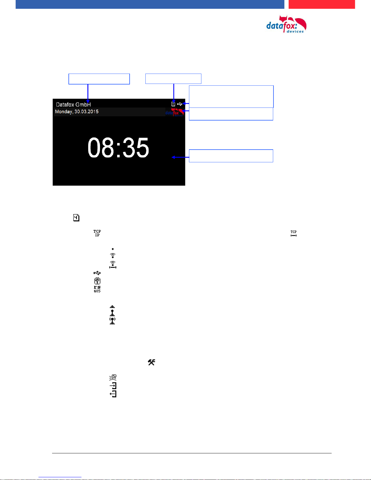
5.2.3.1. Structure display "Normal display"
Date Time corresponds to the system time of the device, which is also used for the data
records.
Number of records in memory (display up to 99, then 99+).
Communication field with symbols for:
o TCP /IP When this communication is active, this symbol is displayed .
o Wlan communication
WLAN as main communication
Wlan connected
Wlan Communication is currently active
o USB
o USB Host (Save the data to USB stick)
o RS 485
o GPRS With status display e.g.[33] See "Status messages on the display".
Mobile modem is off
Mobile modem is switched on, but no connection to the provider.
Mobile modem is switched on, connection to the provider exists.
Display on the display
o The header lines 1 and 2 of the setup are displayed in the main menu.
o The header lines 3 and 4 stored in the setup are displayed in menus and input chains.
o During the transmission of a setup or firmware update, the device enters the system stop and
displays this symbol „ Systemstop“ in this window.
o Display in the left part of the window:
= Transponder input (Accept value of transponder)
= Check in (coming) - booking
= check out (going) - booking
Number of records
Texts according to Setup
Communication status of
the main communication
Display and list box
Field for customer logo
Manual Datafox Evo 4.3 Page 18 Date: 27.12.2017 V 04.03.09.XX
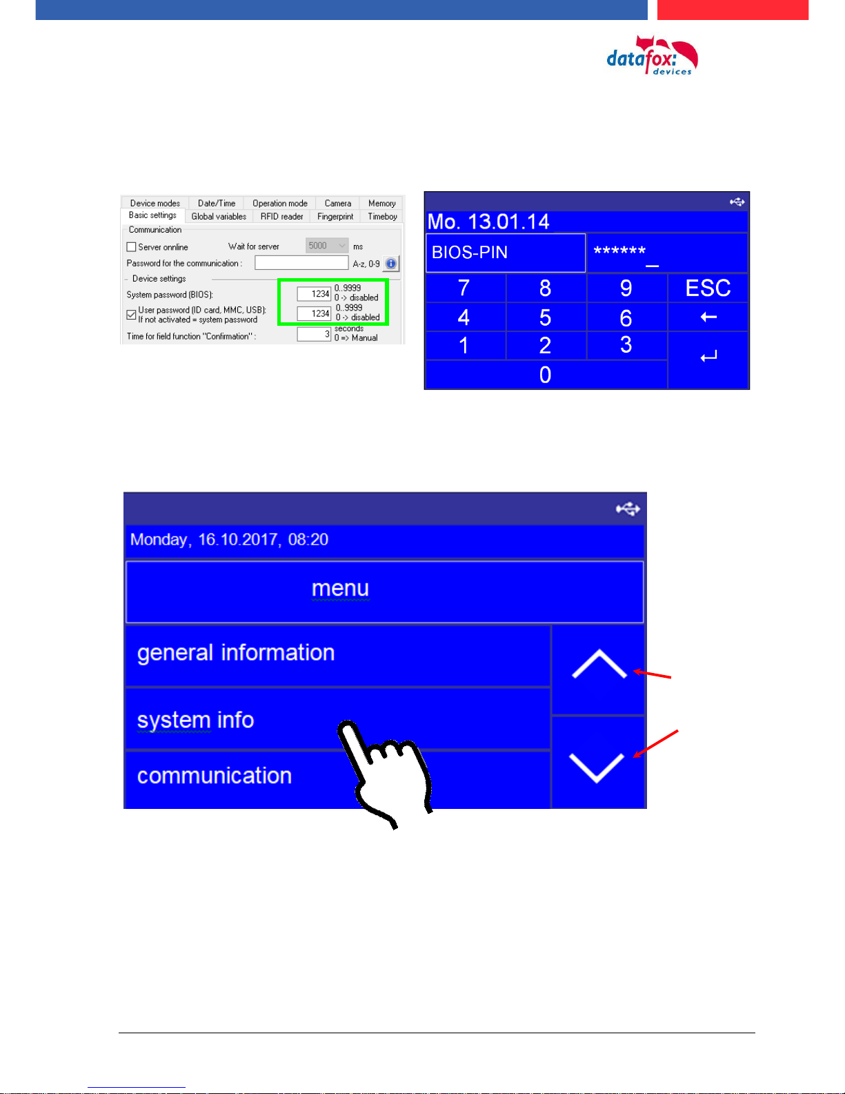
5.2.3.2. Structure Display EVO 4.3 "in the Bios menu
The bios menu is accessed by pressing the button at the same time „ESC“ und „Enter“.
If in the Setup configured a password, you can edit/enter here.
1 display in the bios menu:
To flip the
page, use the
arrow keys
For selection, just tap.
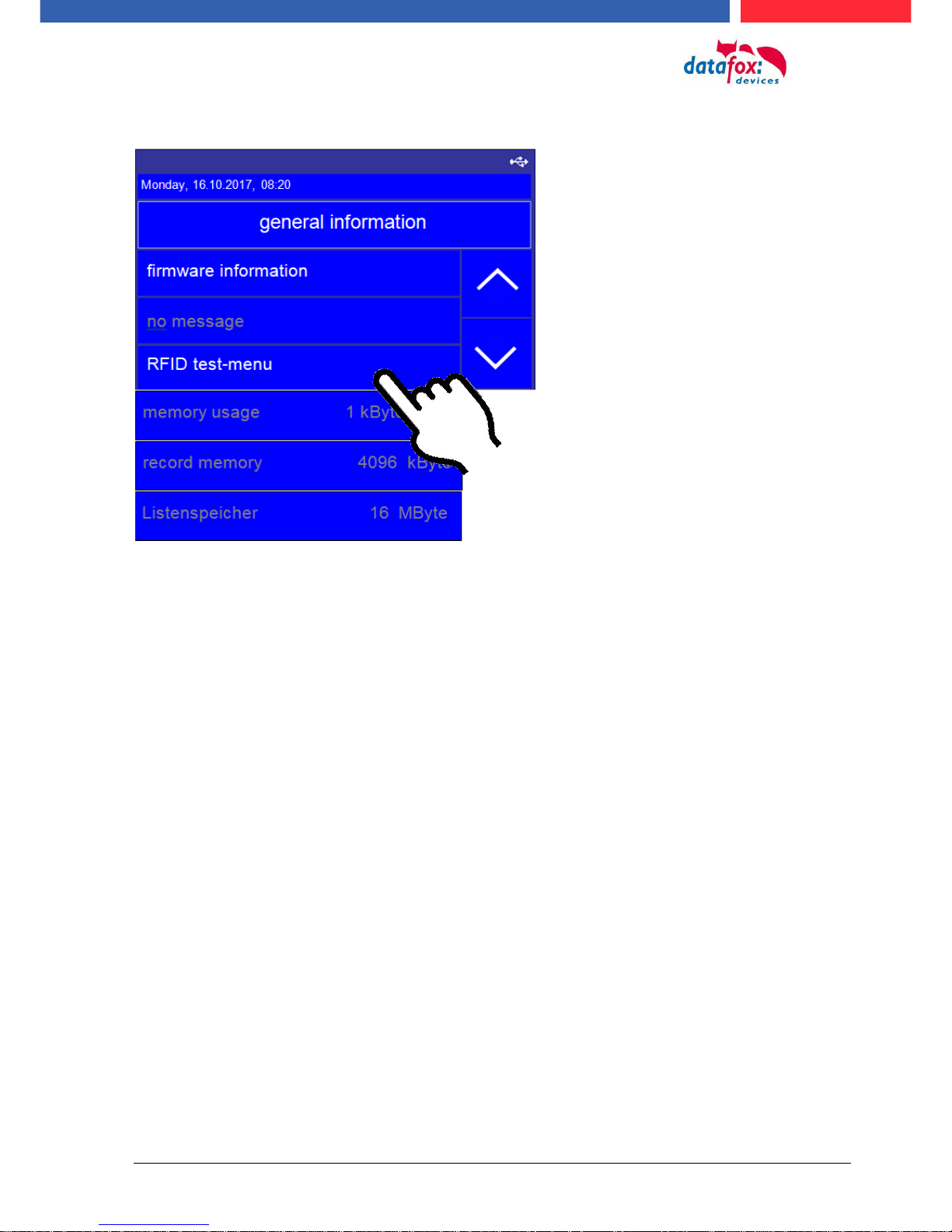
Manual Datafox Evo 4.3 Page 19 Date: 27.12.2017 V 04.03.09.XX
Menu -> general information
Here can you test to read an badge
Here you can test to read the badge
For selection, just tap.
Manual Datafox Evo 4.3 Page 20 Date: 27.12.2017 V 04.03.09.XX
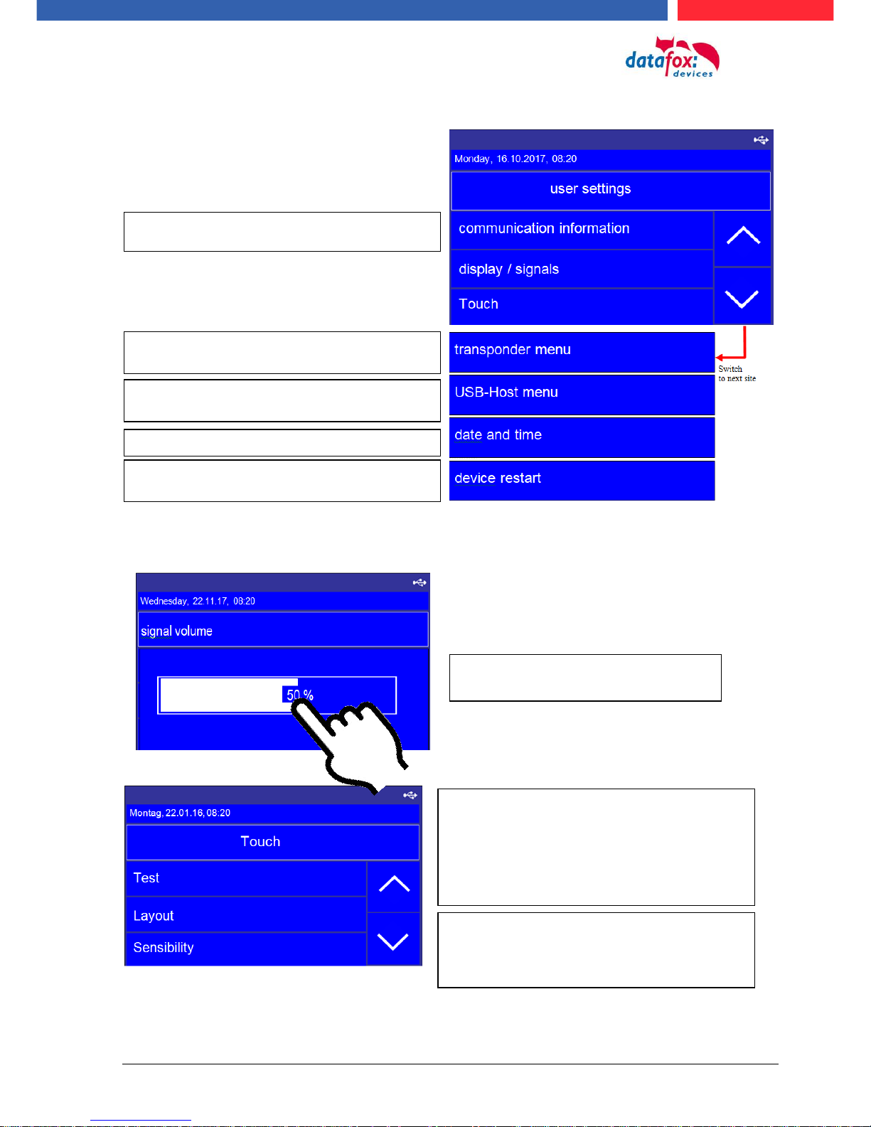
Menu, user Settings:
Menu Anzeige /Signallautstärke -> Lautstärke
Menu Touch:
To adjust the volume, simply tap on
the bar in the display.
Here you get information about the RFID reader
and you can programming badges in this menu.
If set the communication on TCP/IP the see you here the
IP address.
Here you can reboot the device.
Setting for date and time
setting to use a USB Memory stick for data transfer
Testing the toutch!
Test environment for the touch. You will see the entire
touch area on the right and the x-y coordinates on the
left.
You can leve the menu, if you toutch with 2 fingers on the
same time witch 5 cm distance between.
Layout:
Here you can see the defined keys on the touchscreen
such as numbers or ESC function keys.
See the capter: Touchconfiguration and displaydesign.
Manual Datafox Evo 4.3 Page 21 Date: 27.12.2017 V 04.03.09.XX
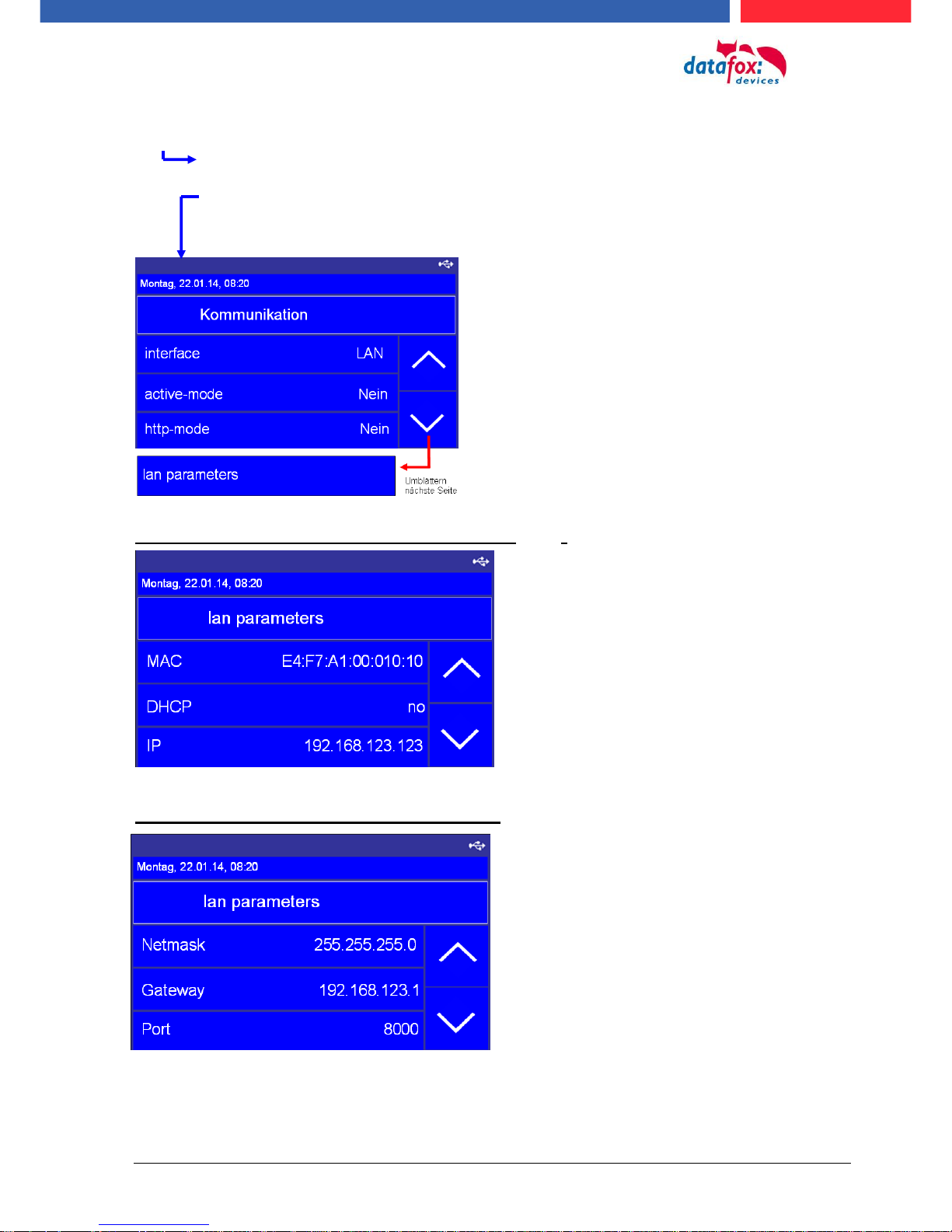
Menu bios:
firmware information
system information
communication
display and signals
date and Time
Setting the LAN parameters TCP/IP (page 1)_(DHCP)
Setting the LAN parameters TCP/IP (page 2)
(here see you the actuelly used communication)
(this is only to used by active connections. If this setting on “yes“,
the is the device not reachable.)
(With this setting use the the device the communication to an
webserver. If this setting on “yes“, the is the device not
reachable.)
(Here can you cange the TCP/IP parrameters.)
e.g. IP-adress, port and more.
MAC Adress, starts by the datafox devices ever with E4:F7.
activate DHCP, automatic IP address assignment
Actually ip-adress. When you use DHCP then can you not
set the IP adress manually.
Here you can set the netmask
Gateway – This settin are neccesarry if send the deveice
data in an other network.
IP-Port-setting
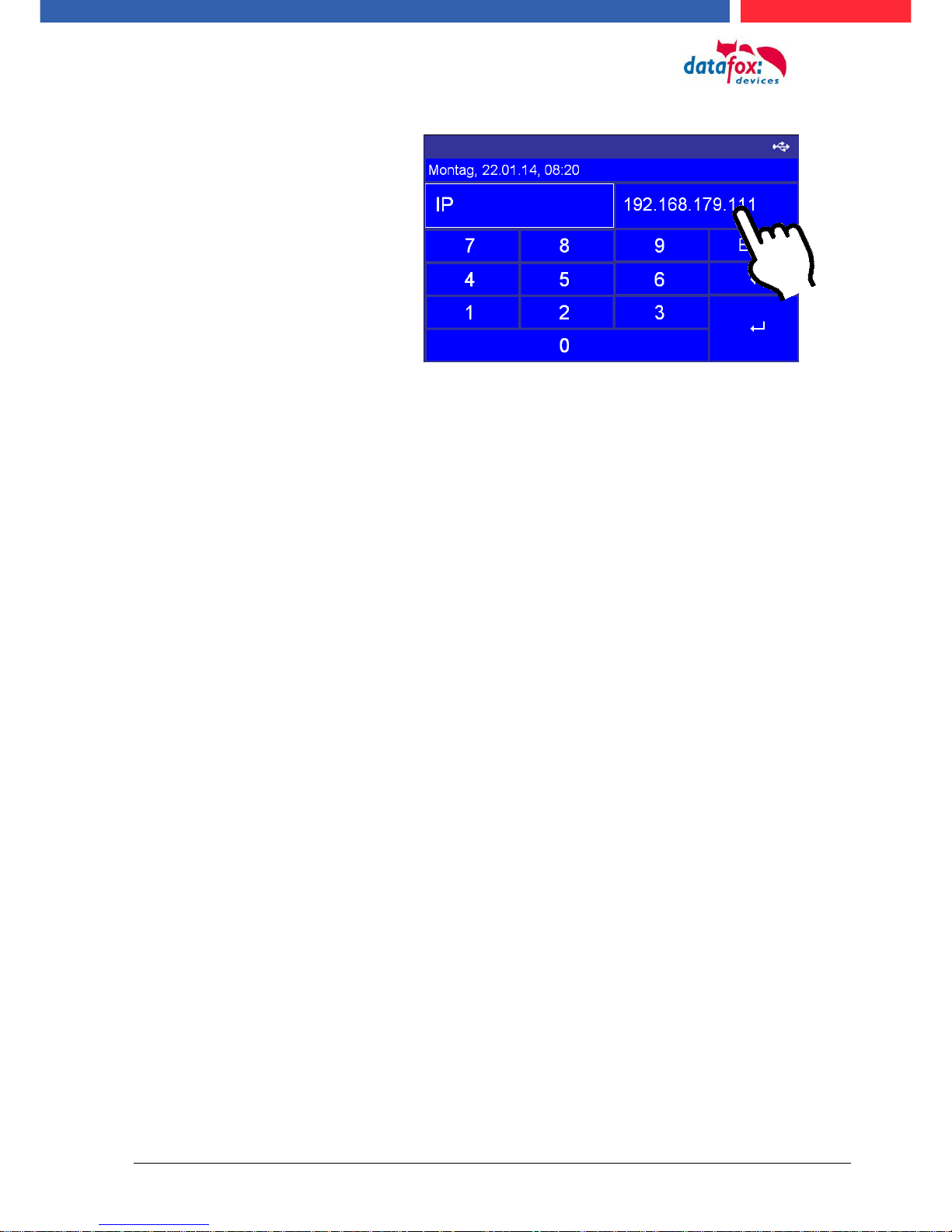
Manual Datafox Evo 4.3 Page 22 Date: 27.12.2017 V 04.03.09.XX
TCP/IP (set IP adress)
Tap with the finger on the possition were you need the cursor.
Manual Datafox Evo 4.3 Page 23 Date: 27.12.2017 V 04.03.09.XX
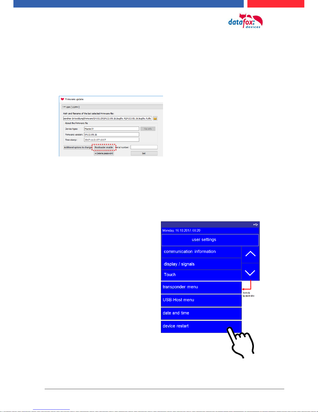
5.2.3.3. activate the Bootloader
In the event that you set an unknown IP address and a bios password is set, there is the possibility
to activate the bootloader. This allows the device to be reset via USB. With the installation of the
firmware and the connection of a setup without bios password, you will have access to the bios of
the device.
Stepp 1:
See the dialog with the DatafoStudioIV and press “Bootloader enable”.
Stepp 2:
Connect the device on USB – PC and restart.
Stepp 3:
See you the message “Bootloader was successfully activated“ then it is possible transfer new firm-
ware to the device.
5.2.3.4. device reboot
In the menu User settings“ it is possible restart the device.
Confirm your cossing with a tipp (enter) on the display.
All data and settings are kept.
Manual Datafox Evo 4.3 Page 24 Date: 27.12.2017 V 04.03.09.XX
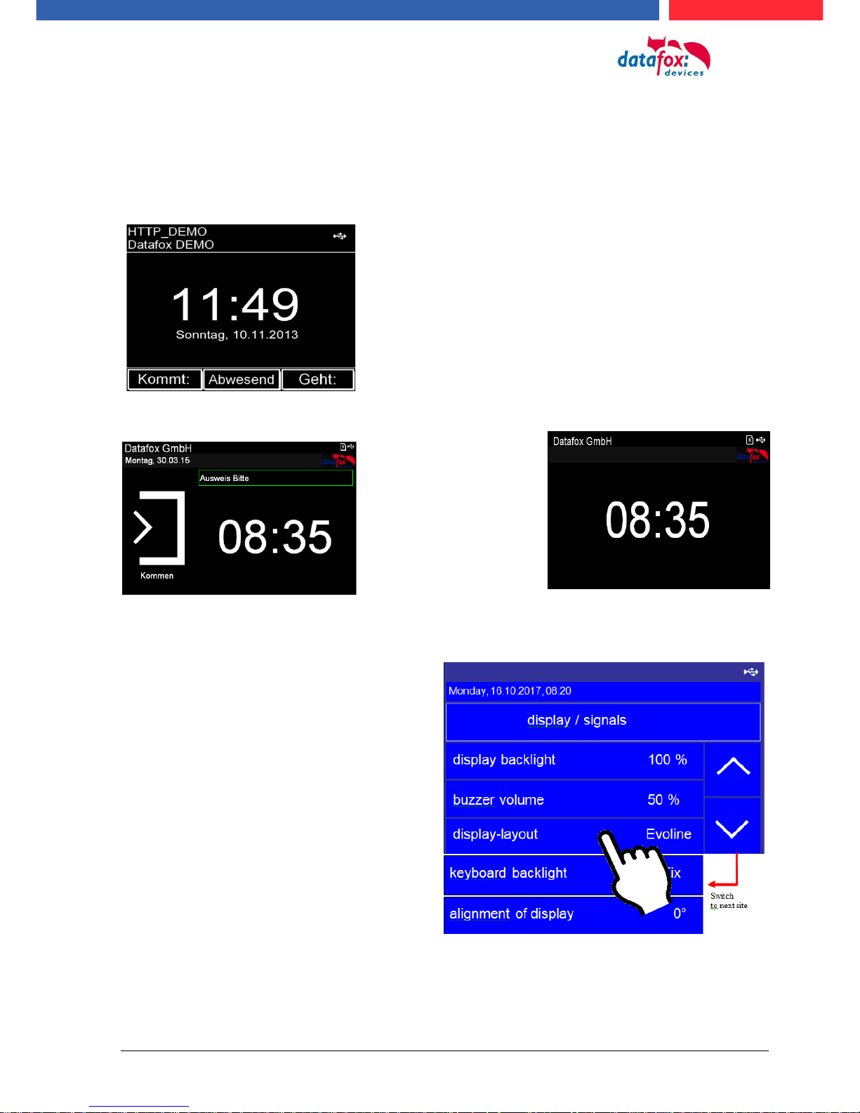
5.2.3.5. switch the display design
The multifunctional terminal EVO 4.3 has 2 different display options.
1.) Display in the PZE-Master Style,
2.) Evolution-Line Style,
This display layout serves to continue to use the
known from the PZE Master IV operating concept.
Also if PZE-Master and EVO 4.3 are used in parallel. In this case, the user does not need to get
used to another operating concept.
Newly revised display
layout for better ease
of use and better clarity.
You can coose the between this two
designs in the menu
“usersettings -> display / signals ->
Display-layout.

Manual Datafox Evo 4.3 Page 25 Date: 27.12.2017 V 04.03.09.XX
5.2.3.6. create an new display design
Examples for the display design:
To create an individual design, you need minimum the DatafoxStudioIV version: 04.03.06.XX.
You find in the DatafoxStudioIV under
“Configuration >Display Desinger“,
the poit to create an individual display design.

Manual Datafox Evo 4.3 Page 26 Date: 27.12.2017 V 04.03.09.XX
5.2.3.7. Key and the Combinations
Note:
Keep to the given order of the key combinations. Otherwise, you will switch to an input sequence and the desired function will not be available.
Activating start options
- Press ENTER key during booting.
Opening device BIOS menu
- press ESC + ENTER in secquence and hold
Navigation in lists
- downward arrow or upward arrow „Touch“
- or slide with the finger over the display
Assyme an chossed list entry
- ENTER-button
Abbord an action
- ESC-button
Chump in the main menu
- ESC-button

Manual Datafox Evo 4.3 Page 27 Date: 27.12.2017 V 04.03.09.XX
5.2.4. Displaydesigner
scope of application:
For the devices AE-MasterIV V4, PZE-MasterIV V4 and PZE-MasterIV Basic V4 is the Designer
only usable for color display.
With the Display-Designer, Datafox offers the possibility for partners and users to customize the
display according to your requirements. But due to the necessary operating sequences, this cannot
be a completely free design, but things like headlines, menu structures and footers have to be guaranteed. The aim of the display designer is to enable the feasible settings with minimal effort.
Wir freuen uns auf viele Anwender und empfehlen:
Create an individual Display-Design for your Company:
Example picture for EVO 4.3
Example picture for EVO 2.8 / 3.5
Example picture for PZE-/ AE- Master V4 with color display
To create an individual ad for your device, you need at least that
DatafoxStudioIV 04.03.09.05.
The display designer can be
open via the Configuration
menu or directly from the
setup edit mask.

Manual Datafox Evo 4.3 Page 28 Date: 27.12.2017 V 04.03.09.XX
5.2.4.1. Color Setting for the Display
5.2.4.2. Default Setting
Function Key’s
are not displayed in the
default setting.
The device is delivery in the
default „PZE“-design.
This design is also set as default when you first create a
new theme in Display Designer.
Example Picture:

Manual Datafox Evo 4.3 Page 29 Date: 27.12.2017 V 04.03.09.XX
By showing the function
buttons from the setup,
the number of buttons
displayed in the display
can be adjusted.
5.2.4.3. Display function buttons on the EVO 4.3 / 2.8 display
Example:
5.2.4.4. Upload images for function buttons of EVO 4.3 / 2.8
Sample picture for the key figures:
Under this menu item "Key
settings" you can import the
image file for each function
key.

Manual Datafox Evo 4.3 Page 30 Date: 27.12.2017 V 04.03.09.XX
5.2.4.5. Design examples in the designer
With the installation of the DatafoxStudioIV you get several design examples for the devices.
Click on the "Design Examples" button to open them.
Datafox gradually extends the examples.
If you have any suggestions or wishes, please let us know.

Manual Datafox Evo 4.3 Page 31 Date: 27.12.2017 V 04.03.09.XX
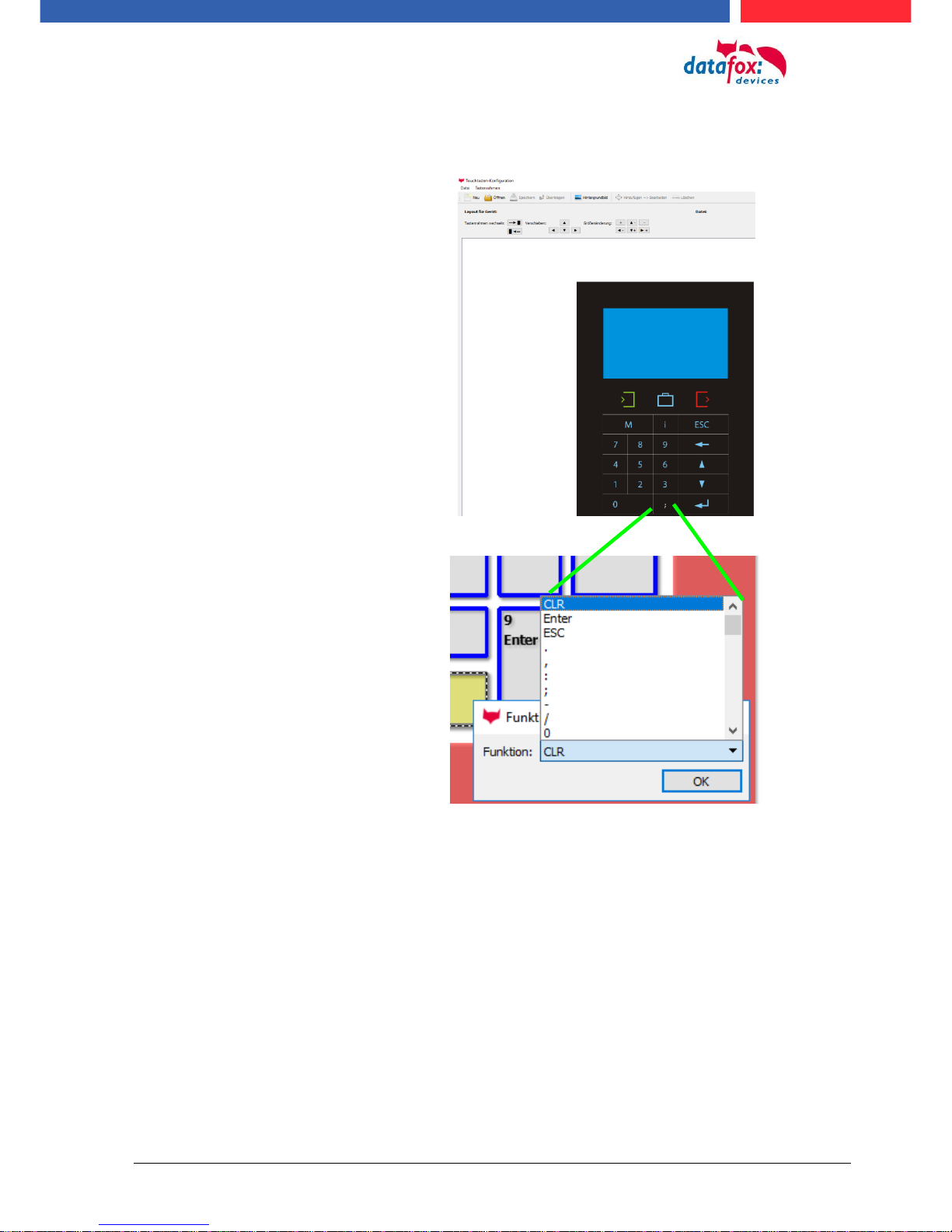
5.2.5. Configuration of the touch
You access the menu via:
Select "Add Touch Position" to create individual keys. With each click in the area that is allowed for
keys, another key is added
Via "File New", you can create a new
touch configuration.
Note:
The size and position of the
keys can be perfectly aligned
based on the position in the
table.

Manual Datafox Evo 4.3 Page 32 Date: 27.12.2017 V 04.03.09.XX
5.2.5.1. Key-picture adn key pad
To ensure that the keyboard layout matches the configuration of the touch screen exactly, you can
display the print image.
Note:
The background image must be in JPEG format with the dimensions 133,4mm X
194,4mm and a resolution of 300dpi.
Note:
Various pictures and preconfigurations can be found on the product DVD and on our
homepage.
5.2.5.2. Transfer the touchconfiguration
The created configuration for the
touch screen is saved in a
". dfk" file. You can enter these
here and transfer them to the terminal.

Manual Datafox Evo 4.3 Page 33 Date: 27.12.2017 V 04.03.09.XX
5.2.5.3. Create an cange the keys
Change / define function:
Move key:
change the key size:
larger sideways: Shift+arrow right ()
greater height: Shift+arrow down ()
larger than two pages: plus button (+)
smaller sideways: Shift+arrow left ()
small height: Shift+arrow up ()
small two pages: minus key (-)
Mark the key to be edited with a click.
It then changes colour.
With a right click on the button, you
can select the function of the button.
Move,
you can press the key with the
Arrow keys on your keyboard.
Manual Datafox Evo 4.3 Page 34 Date: 27.12.2017 V 04.03.09.XX
5.2.5.4. Available character set in the touch field
This means that special characters and letters can also be entered with the touch screen.
The availability of the characters for the touch layout has
been extended:
:
;
/
“
%
(
)
*
+
<
>
_
and letters A-Z

Manual Datafox Evo 4.3 Page 35 Date: 27.12.2017 V 04.03.09.XX
5.3. switch collours of the backligth
the follows backligths can you control via terminal setup:
► Backligth of the keboard (only in white in in 255 stepps)
► Backligth of the RFID-reader (RGB-colour and white in 255 stepps)
► Backligth of the company symbol (RGB-colour and white in 255 stepps)
Note:
The generated colors of the RGB Led's do not always correspond to the color perception
of the user. Please adjust the colors to your needs.
Help for the mixed colour:
colour
part of red
part green
part blue
part white
yellow
255
100 0
turquoise
0
255
255
orange
255
35 0
pink
217 0 108 red
255 0 0 green
0
255 0
blue
0 0 255 white
0 0 0
255
Posibilitys to switch the backligth „Time“:
- Permanently, the lighting is switched immediately
according to the color setting or brightness and
maintained even after the execution of an input sequence.
-
- For a define time,
- Up to the next input field, after the end of the next
input field swith the backligth back to the settings
bevore.

Manual Datafox Evo 4.3 Page 36 Date: 27.12.2017 V 04.03.09.XX
5.3.1. Switch lighting depending on the result
With this function you control e.g. the signaling of a valid / invalid transponder.
The distinction between valid or invalid is determined by a selection from a "personnel list".
If the number of the ID card is not found in the list, the list box is ended with an "ESC". That the color of the lighting can be controlled depending on the result.
Find by the list selection no entry, then switch the backligt to:
„Result: ESC“
Find the selection an entry, then
switch the backligth to:
„Result: OK“

Manual Datafox Evo 4.3 Page 37 Date: 27.12.2017 V 04.03.09.XX
5.4. Installation of the EVO 4.3 Terminal
The wall mounting takes place by means of a wall bracket. This is attached to the wall via 3 attachment points.
Fixed scew
The terminal is
mounted at the to.
On the down site
kann you fixed the
terminal ith a scew.
The attachment points are
compatible to the PZEMaser.
Torx T8

Manual Datafox Evo 4.3 Page 38 Date: 27.12.2017 V 04.03.09.XX
5.5. Connecting of EVO 4.3
5.5.1. Connecting plugs EVO 4.3
The Evo 4.3 have intergatet 7 modulplaces. On this places can you order different modules.
You can choose the modules on the pricelist.
Here see you an example with some different modules:
Bezeichnung
Modul
PIN
Beschreibung
digital IO
1x digi. IN
1x digi. OUT
M1
4-5
1-3
1 digital input
1 digital output with normaly open and normaly close
RS485
for
access
control
M2
1
ground
2
A RS 485 for access control
3
B RS 485 for access control
4
12 V
Digital IO
4x digi. IN
M3
1
1 digital input
2
2 digital input
3
3 digital input
4
4 digital input
5
ground
RS485
for main communication. Connecting
derectly to an PC
M2
1
ground
2
A RS 485 for main communication
3
B RS 485 for main communication
4
not connect
digital IO
1x digi. IN
1x digi. OUT
M5
4-5
1-3
1 digital input
1 digital output with normaly open and normaly close
Modulplatz 6
RS 232
Mini-DIN M004
M6
1
TXD
2
RXD
3
+ 5 V
4
Ground / GND
Modulplatz 7
M7
TCP/IP - LAN
RJ 45
connectors V4.x Evo 4,3’’
LAN
RS232
M2
M3
M4
SIM
12VDC
USB
GPRS
GPS
M5
M6
M7
M1
485-A
485-B
GND
12 V
D IN1
DGND
D IN2
D IN3
D IN4
DGND
D IN1
Relay
AC
485-A
485-B
MC
DGND
D IN1
Relay

Manual Datafox Evo 4.3 Page 39 Date: 27.12.2017 V 04.03.09.XX
5.5.2. Powersupply of the EVO 4.3
5.5.2.1. Powersupply
The delivery power supply have 12V DC / 18 W.
The terminal itself can be supplied with a supply voltage of 24 V DC.
The power supply:
5.5.2.2. Power via POE
An option for the power is a POE-modul (Art. Nr: 115117).
This POE-modul supporter 2 standards.
PoE-Standard
power
useable power
PoE
IEEE 802.3af
15,4 Watt
12,95 Watt
PoE+
IEEE 802.3at
25,4 Watt
21,90 Watt
If power is supplied via POE, an external access-reader can also be supplied via the access control
plug.
Reverse polarity protected connector

Manual Datafox Evo 4.3 Page 40 Date: 27.12.2017 V 04.03.09.XX
5.5.3. Modules for devices of hardware V4
5.5.3.1. Description of the various extension modules
The Datafox devices of the generation V4 are particularly distinguished by the variable configuration
of individual modules.
Depending on the device, a certain number of module locations are available.
These can be individually equipped with the individual available modules.
Depending on the size of the module, the individual modules occupy one or two module locations.
Thus, e.g. the GPRS module (mobile radio) requires 2 module slots and one relay module only
needs one module slot.
Overview of the different optional modules:
modul description
Required
module
slots
Description in the
BIOS-Menu and
Module mumber.:
Max. possible
number of
module
items
No. for
the
plug
overprint
&
Colour
RS 232 - mini DIN Barcode
1
032 Serial port mini DIN
1
RS 485 access
1
014 RS485 + 12V Supply
3
A310000
4-01
RS 485 for main communication
1
035 RS 485 Com Port
1
GPRS Mobile (Cell phone)
network
2
Mobile MC 55i
1
TCP/ IP
1
011 Ethernet Port
1
WLAN (WiFi)
1
001 WLAN Red Pine
1
2x digital Out
1
005 Relais Output
8
A310000
5-01
1x digital In +
1x digital Out
1
012 Digital In-/Output
8
4x digital In
1
006 Digital Input
8
A310000
5-02
4x anlog In
1
008 Analog Input
8
A310000
5-03
How manny modulplaces are usable you see device in the device manual in the chapter “Connec-
tion of device”.
5.5.3.2. Read the optional placement of the device
Click on:
„Configuration -> Device configuration (Bios)“
Then click on „Read“.

Manual Datafox Evo 4.3 Page 41 Date: 27.12.2017 V 04.03.09.XX
Display in the Bios-Menu:
Here show all moduls they are fited in the device:
You see which module on which place is. You get extendet information how MAC adress, the number and order of the inputs and outputs.
E.g. Type lable of a IO-Box V4:
Example 1:
- Modulplace = M1
- Digital Input 1 to 4
- Module Number: = 006
Example 2:
- module slot = M4
- Analog Input 5 to 8
- Module Number: = 008 analog Input
You see here, in the IO-Box are
8 Modulplaces usable. This can be indi-
vidually fitted.
Exceptions:
- Modulplace 8, only here TCP is possible.
- RS 485 for access control - maximum 4
Modules can be fitted.

Manual Datafox Evo 4.3 Page 42 Date: 27.12.2017 V 04.03.09.XX
5.5.3.3. Read out important module information from the device
Click on:
"Configuration -> Device Configuration BIOS"
Then click on "Status" thereafter
Click "Read".
1
2
3
4
5
6
7
8

Manual Datafox Evo 4.3 Page 43 Date: 27.12.2017 V 04.03.09.XX
Here you will find a whole series of important information about the terminal.
Here are some explanations of the individual lines:
1) Name of the setup, this is also available when reading out.
2) The date when the setup was loaded into the device.
3) State of the digital inputs. All inputs which are physically present and defined in the setup are displayed
here with their status.
a. 00000000 = Digital inputs defined in the setup
b. 0 = Input on low (logical 0)
c. 1 = Input on hi (logical 1)
4) If digital inputs are defined in the setup as counter, the current count value is displayed here.
5) Status of the digital outputs: Output 1 is continuous here from left to right.
6) Analog inputs from left to right with respective currently applied voltage.
7) Number of stored records in the device and memory used.

Manual Datafox Evo 4.3 Page 44 Date: 27.12.2017 V 04.03.09.XX
5.5.3.4. Connection of the individual modules
The connector / socket for the module always has the following assignment:
5.5.3.5. Analogeingänge, 4 mal analog IN - Analog inputs, 4 times analog IN
Socket on the device:
1 2 3 4 5
The plug can be inserted only in one direction and is therefore protected against reverse polarity.
plug
1 2 3 4 5
To loosen the cable, use a small screwdriver. Solid wires can be loosened by
twisting back and forth on the wire and
plug.
+ 0-10 V Signal 4
+ 0-10 V Signal 3
+ 0-10 V Signal 2
+ 0-10 V Signal 1
common ground;
GND / Ground

Manual Datafox Evo 4.3 Page 45 Date: 27.12.2017 V 04.03.09.XX
5.5.3.6. 2 mal digital Out - 2 times digital out
Connection example:
(Connection of a signal light and a signal horn via a potential-free contact):
5.5.3.7. 1 time digital Out 1x digital IN
Connectiom example (Connection of a signal light and a door contact):
5.5.3.8. 4 times digital IN
Connectiom example (Connection of 4 contacts):
max. 42V AC /
2A / 60W
max. 42V AC / 2A / 60W
e.g .: Door contact
max. 30V
0 - 1,5 V Input logical 0
3,5 V - 30 V Input logical 1
e.g.: 4x digital in
max. 30V
0 - 1,5 V Input logical 0
3,5 V - 30 V Input logical 1

Manual Datafox Evo 4.3 Page 46 Date: 27.12.2017 V 04.03.09.XX
5.5.3.9. RS-485 Bus für ZK – RS-485 bus for access control
The access control option provides the connection for external readers on the device.
The pin assignment looks as follows:
Note:
The 12 V are only present when the access control on the device is activated and all access lists have been played on the device.
Furthermore, the connection for a digital input and output is available.
The pin assignment looks as follows:
How the individual access components are connected or wired, can be found in the chapter "Access
control"
12V +
GND -
The power supply is sufficient for max. 1
external reader.
This voltage must not be combined with
other voltage sources.

Manual Datafox Evo 4.3 Page 47 Date: 27.12.2017 V 04.03.09.XX
5.6. Communication of Hardware V4 Devices
!
Caution:
The type of communication depends on the device.
All possible communications are listet in the device.
Note:
Datafox-devices are able to communicate encrypted.
Read more in the manual for the „DatafoxStudioIV“.
The switching of the communication can be done
via :
1. the system menu bios on the device
2. with firmware version 04.02.04 and up with the function „Switch communication“.
3. from the Firmware version 04.02.04 upwards with the fieldfunktion „switch communication“.
Read more in the manual for the „DatafoxStudioIV“
Mögliche Kommunikationsarten sind:
1. USB (on PC)
2. USB Host, Save data on a USB-stick
3. TCP/IP over LAN
4. TCP/IP over the internet (with HTTP)
5. TCP/IP over WLAN
6. GPRS connection with mobil cell network.
5.6.1. Communication via USB
Every EVO-Line Device is equipped with an usb interface.
The Micro-USB-B Port can be connected directly to a PC.
!
Caution:
The Terminal works with a USB-B Interface. Das heißt, dass das Terminal im SlaveModus arbeitet und kann daher keine anderen USB-Geräte verwalten. This means that
the device works in slave mode only. So it is not possible for the device to control any
other devices via USB.
Manual Datafox Evo 4.3 Page 48 Date: 27.12.2017 V 04.03.09.XX
5.6.2. Automatic dedected conectet USB to PC
If the terminal is connected to a pc it will recognize the connection and will switch the communication to USB.
It is not necessary to switch the main communication to usb manually.
It’s especially useful for boxed devices.
This will save much time in the parameterizing process.
Note:
If the device is connected to a pc no other connections (for example Wi-Fi) will happen
If the USB-cable is disconnected it will automatically switch to the configured main communication
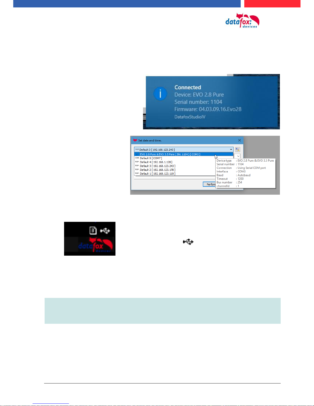
DatafoxStudioIV will recognize the device and a notification will pop up.
The studio will generate
an entry for the device.
On the device the following icon is displayed:

Manual Datafox Evo 4.3 Page 49 Date: 27.12.2017 V 04.03.09.XX
5.6.3. Installing USB driver for Hardware V4 Devices
Installation for Windows 7, 8, 8.1 and 10.
The USB-Driver is a small installer which will do the necessary configuration.
Just launch the .exe file.
Follow the instructions on the screen:
!
Caution:
Only use the driver wich are delivered with the device!
Note:
If you have DatafoxStudioIV installed the USB-driver will already be installed on your
pc.
Manual Datafox Evo 4.3 Page 50 Date: 27.12.2017 V 04.03.09.XX
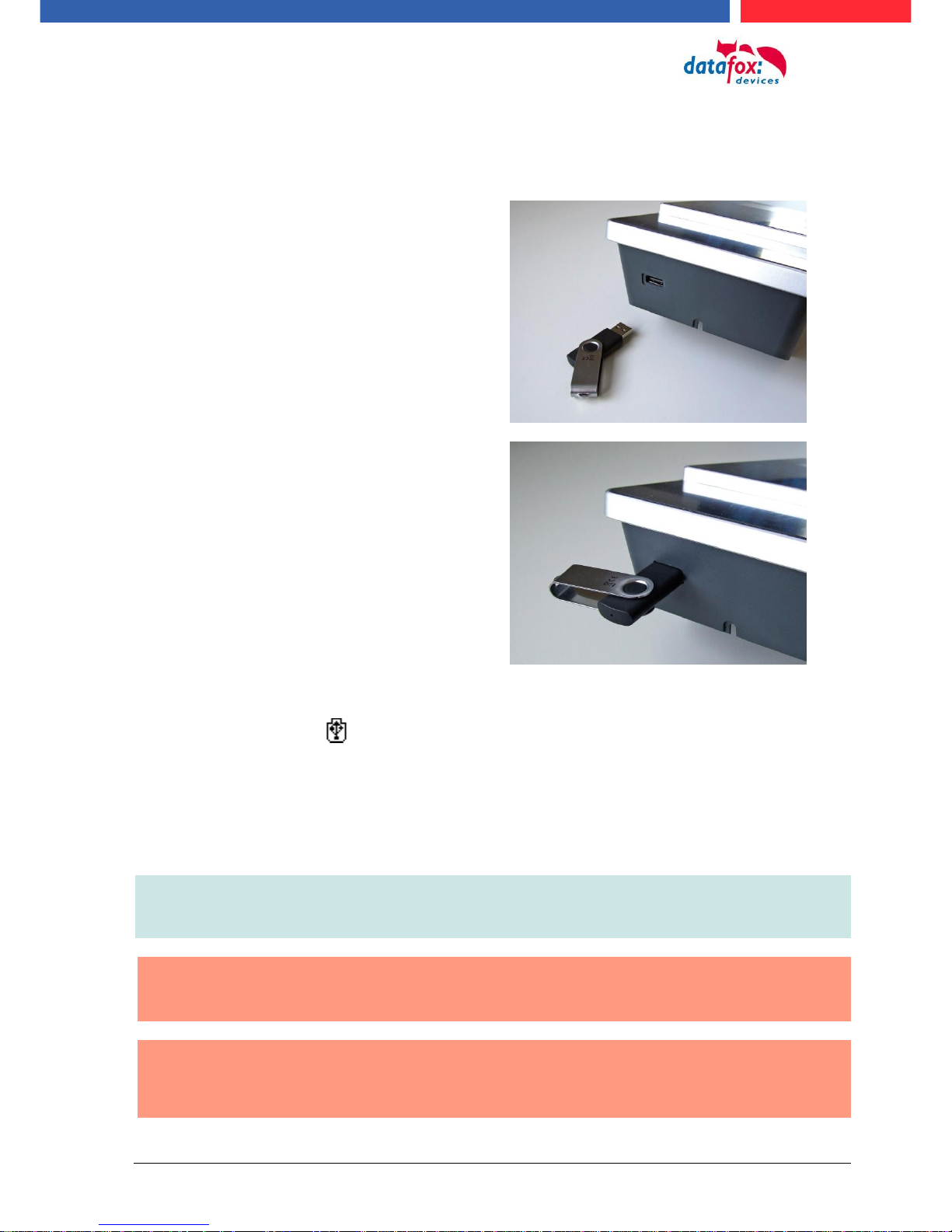
5.6.4. Comunication / record transfer via USB-Stick (Host)
The device dedected the stick automaticaly when the stick is plugged in.
The main communication must be set on “USB-Host“. You see the activated main communiction on
this symbol Symbol (Icon) .
The main communication can you set in the bios-menu.
USB - Stick adjust:
The USB stick is configured with the help of DatafoxStudioIV.
You find the configuration menu under the point „Configuration“->Configure USB flash drive.
More description you find in the manual “DatafoxStudioIV“.
Note:
We recoment to use a passoword for the communication with the USB-stick.
!
Caution:
The usb cable to the PC must not be connected if you want to use the stick on the device
!
Caution:
Lists of access control can be transferred individually, operation lists must always be
transmitted in complete form. All lists defined in the setup must also exist on the stick in
the "List" directory.
To be able to transfer data from the device to a
USB stick, the device must have the option
"USB host".
You can see this at the neckline.
The USB-Stick must be in FAT(32).

Manual Datafox Evo 4.3 Page 51 Date: 27.12.2017 V 04.03.09.XX
5.6.4.1. Error message by using USB-Stick (Host)
Error code
Description
1
Read error
2
Write error
3
Error during the communication with the USB host
4
Error during the changing the directory
5
Error by the check of the stick
6
Error by the list directory
7
Error to create a data directory
8
Error handle
9
Error to open a file
10
Error not find the path
11
Error, the file is already open
12
Fehler to open a file
13
Error by closeing the file
14
Error by closeing the file, false handle
15
Error by checking the handle
16
Error by checking the handle, the file is not open
17
Error write protect
18
Error by the record stucture
19
Error duren the firmware update
20
No USB stick
21
Incorrect password
22
No list
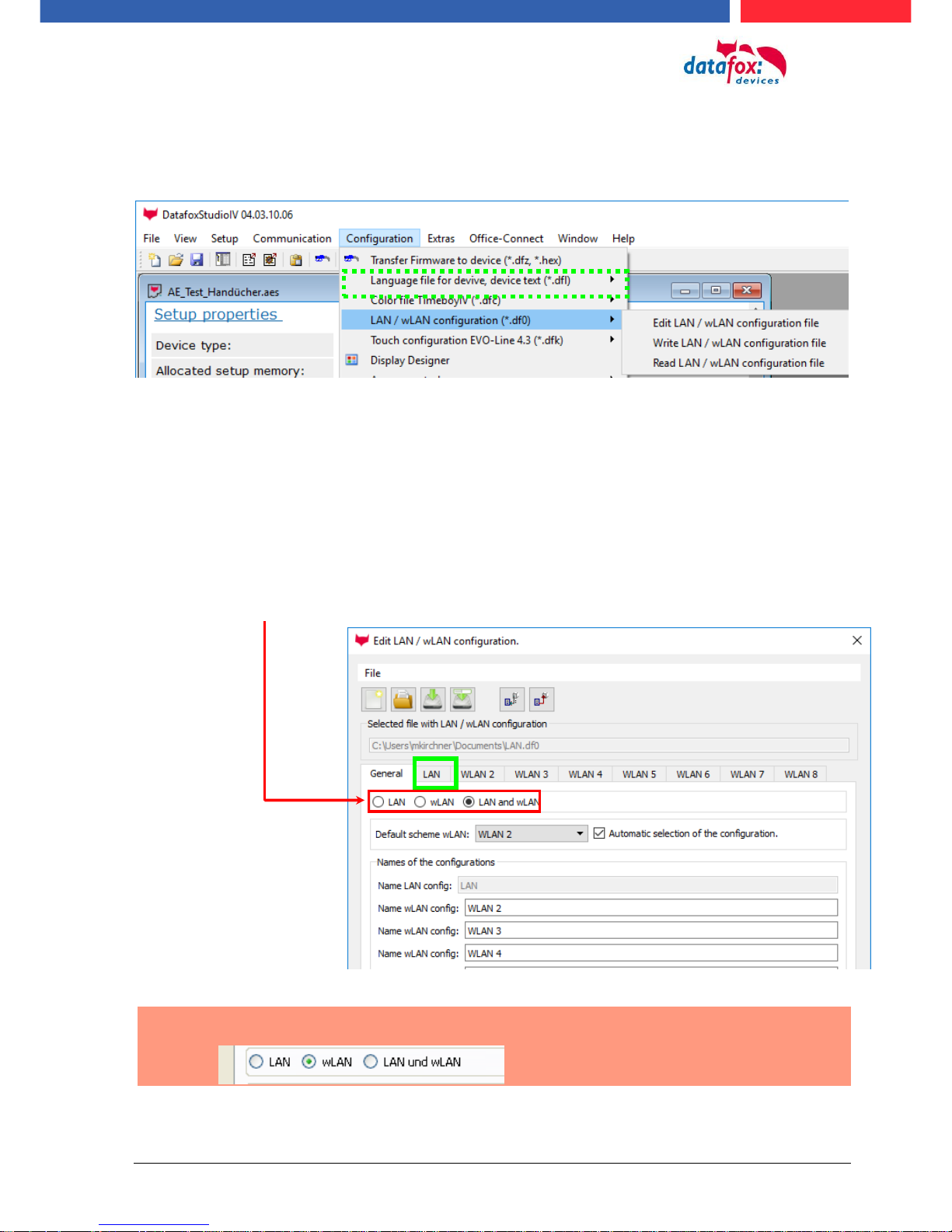
Manual Datafox Evo 4.3 Page 52 Date: 27.12.2017 V 04.03.09.XX
5.6.5. Communication via TCP / IP
The setting of the LAN / WLAN parameters is done via DatafoxStudioIV under the menu item "Configuration" -> "LAN / WLAN – Configuration (*.df0)“.
The LAN / WLAN configurations are saved in a file with the filename extension "*. df0".
Here you now have the possibility to edit the file, load it into the Datafox device (upload) or read it
from the device (download).
When reading the WLAN setting from the device, the currently specified file is overwritten.
In the General tab, first of all, you can set the main communication with which the device is
equipped.
- Device with LAN (The first configuration is for LAN connection)
- Device with WLAN
- Device with LAN and WLAN (The first configuration is for the LAN connection)
!
Coution:
For TimboyIV only this setting (only wLAN) can be used.
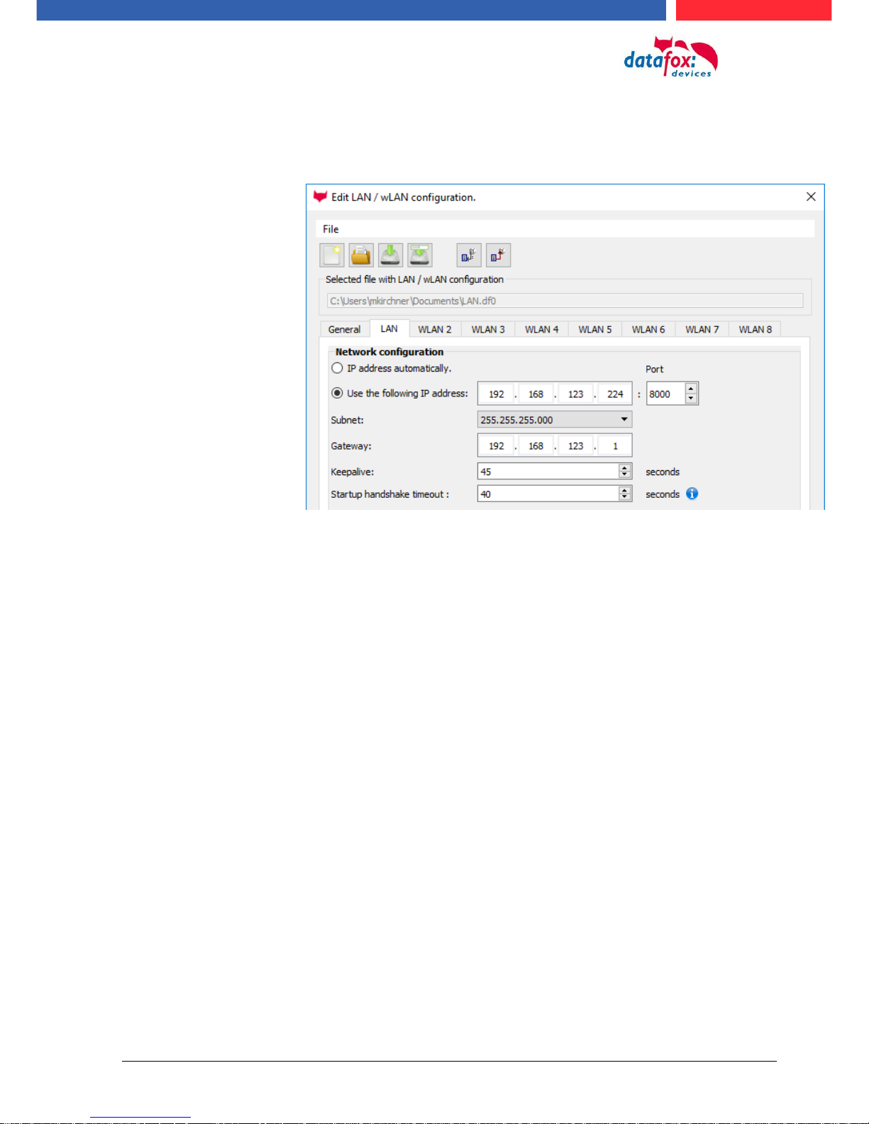
Manual Datafox Evo 4.3 Page 53 Date: 27.12.2017 V 04.03.09.XX
5.6.5.1. Communication TCP / IP via network-cable
You can make the IP settings on the "LAN" tab.
For devices with display, the IP address can also be entered directly on the device.
Press ESC and ENTER simultaneously to enter the Bios menu of the device.
More information can be found in the chapter „bios menu“.
Please enter the desired IP address, subnet and if necessary a
gateway.

Manual Datafox Evo 4.3 Page 54 Date: 27.12.2017 V 04.03.09.XX
5.6.5.2. Communication TCP / IP via wLAN / Wifi
This overview shows you which WLAN methods are supported.
Not supported is WPA (Predecessor of WPA2).
5 GHz connections are not supported and no mixed operation 2.4 GHz / 5 GHz.
Authentication via WPA2 Enterprise according to IEEE 802.1x is not supported.
!
Attention:
We cannot test every available Acsess-Point on the market.
Therefore, it is not possible for us to guarantee a connection to any AP.
When setting the encryption AES or WEP, only one type is used at a time.
The setting AES+WEP means for some access points that AES encryption is performed first and
then additionally encrypted with WEP.
In this case, only set AES.
Security:
None (0)
ohne
Security:
WEP(1)
WEP64
WEP128
Authentication
Open/None (0)
Shared/PSK (1)
NO Key
WLAN / Wifi – overview about
the encriptions and
„Infrastructure“
Encryption
Security:
WPA2/802.11i
AES / CCMP
„AES 128“
AES / CCMP +
WEP
Authentication
Shared/PSK
Encryption

Manual Datafox Evo 4.3 Page 55 Date: 27.12.2017 V 04.03.09.XX
!
Attention:
A search for a new access point requires a lot of energy and drains the battery. Avoid a
continuous search for an access point when the device is operating at the limit by generously selecting the pause between scans for new access points (80-120s).
At most access points there is the possibility to set the "Beacon Interval". The higher this
is set, the less power the TimeboyIV needs. Recommendation: Beacon interval >300ms.
The entire file with all settings is transferred to the device. If the device has a display, the location
can be selected in the Bios menu -> Communication -> WLAN. Each location has its own configuration for the WLAN connection. The user therefore has no insight into the dial-in parameters at the
various locations.
Hint:
With automatic selection of the configuration / location, the first attempt is always made to
establish a connection with the default schema.
Select the configuration or location for
which you want to set the WLAN parameters.
If you check this box, the battery
life will be significantly increased
if the device is operated with a
rechargeable battery. Important
for TimeboyIV!
All the settings required for an access
point can be made here.
If a key is stored, this will be
displayed.
A scan (search) for access points is only carried out after a disconnection after this set time.
Please note the following Attention Box!
Enter the IP address for the device
here.
This must be the same for every location.

Manual Datafox Evo 4.3 Page 56 Date: 27.12.2017 V 04.03.09.XX
5.6.5.3. Location selection in the Bios menu WLAN
5.6.5.4. Recommended setting
We recommend the following setting:
- WPA2
- AES
- Shared/PSK
Datafox uses the following access points internally for testing:
- Longshine LCS-WA5-45 IEEE802.11g
- WatchGuard XTM WEB UI
- Longshine IEEE802.11n
- TP-Link WR841N v6/v7 00000000
Setting StudioIV_WLAN-Device
Setting Access-Point
15.08.11 11:28:08
Datafox Support 74db
F1
F2
Datafox Gast 74db
Standort Geisa 86db
FA Muster 90db
Bios
Akt. Konfig.
?
?
All available WLAN networks are displayed in the Bios.
A configuration is stored for these networks
and can be selected.
These two networks were found by the
WLAN module, but there is no dial-in data available.

Manual Datafox Evo 4.3 Page 57 Date: 27.12.2017 V 04.03.09.XX
5.6.6. Communication via Cellular Network (GPRS)
The EVO 4.3can be equipped with a cellular network modem. It enables the communication via cellular network. The antenna is located in the connection compartment of the device and can optionally be replaced by an external antenna if reception is bad.
The SIM card is inserted via the connection compartment of the EVO 4.3.
Einsetzen der SIM-Karte beim EVO 4.3
Einsetzen der Sim-Karte beim Gerät
!
Caution:
For inserting the SIM card a tool in pen or screwdriver form is required. Take care that
the SIM card is not damaged.
For removing, the SIM card has to be pushed in a bit. After releasing it, the SIM card protrudes a bit
and can be removed.
Hinweis:
Wir empfehlen T-Mobile oder Vodafone als Provider für Mobilfunk einzusetzen! Unsere Erfahrung zeigt, dass bei anderen Anbietern mit häufigeren Einwahlen und damit auch verzögerter Datenübertragung und ggf. mit höheren Kosten gerechnet werden muss.
Informationen zu M2M:
http://www.t-mobile.de/business/machinetomachine/m2m-im-einsatz/0,23219,26762-_,00.html
The SIM card must be inserted into the
device in this position.
Mind the bevelled corner

Manual Datafox Evo 4.3 Page 58 Date: 27.12.2017 V 04.03.09.XX
5.6.6.1. Communication state
The state of GPRS-/GSM-connection you can always see in the state bar on the display.
Pin
Bez.
0
Modem is off
1
Initialization of the software
2, 3
Start of the modem
4, 5
Initialization of the modem and SIM-card check
6
if PIN necessary, sending of the PIN
7
if PUK necessary, sending of the PUK
8
dilated initialization of the modem
10
Modem in standby mode
11
Call recognized
12
take calls
14
GSM connection activ
15, 16
GSM connection closed
20
GPRS Standby, Initialization of the GPRS connection after the first records
25
connection to Provider (Attach)
30
GPRS standby (waiting for next data/records)
31
Server (Open)
32
connect to server
33
send data to Server (HTTP)
34
Wait for quitting from server (HTTP)
35
recive data from server (TCP/IP)
36
send data to server (TCP/IP)
37
close connection
38
Braek between tries to connect the server, active mode
40
timeout after failed connection , to 15 minutes
411)
timeout after failed connection Provider, to 15 minutes.
421)
count of the connection attempt is end
43
on the Device is the encryption active, but not on the server
44
battery is down, to disable Modem.
45
impossible connect to the provider or bzw. Roaming impossible
50
close connection
55
Turn modem off

Manual Datafox Evo 4.3 Page 59 Date: 27.12.2017 V 04.03.09.XX
5.6.7. Communication via SMS
5.6.7.1. Send a SMS
With the EVO 4.3, it's possible to send an SMS. Condition for this is, an integrated GPRS-Modem
(communication via Cellular Network). The main communication must be set on GSM or
GPRS/GSM.
To send an SMS you must use the Field Function “send SMS” in the device Setup.
!
Caution:
Enter the phone number always with a country code.
Example.: +49161458
The device can be saved 128 SMS. Then there is additional as follows to clear the oldest SMS.
The call number if you want send an SMS must be saved in a GV.
The maximum length of the SMS is 160 characters.
The text can integrated device value:
%%: The percent signs self.
%V1 to %V8: value of global variable.
%T1: date and time 2012-08-07 12:13:14
%C1: Short device description. (PZE, AE, TIMEBOY, ...)
%C2: Serial number of the device. (max. 10 Stellen) %1 für GV 1, %2 für GV2 usw..
The function „send
SMS“ can you use in a
input field.

Manual Datafox Evo 4.3 Page 60 Date: 27.12.2017 V 04.03.09.XX
5.6.7.2. Receive SMS
The follows functions are possible:
► View the SMS on the display. The sam action you find in the „DFCComSendMessage“ or
the answer via HTTP.
► to order an service connection (the same how in the HTTP- answer)
► start in the signal processing an input sequence
► Output an acoustic signal
Condition to receive a SMS is a KEY include in the device an in the text from the SMS.
The Key fort he device can set in the GPRS/HTTP .ini file.
Textmassage
The keyword must be included in the SMS-text is:
message=text1 text line2 line3 etc.
&delay=10&key=12345
The 10, is the time how long to display the message.
After the character gives a line break (carriage return).
If not a key in the device, you can use the serial number as a key (default setting). Save you an
empty Key, then receive the device every SMS. The last received SMS can you see in the
Bios-Menu under „general information Bios (Menu)“.

Manual Datafox Evo 4.3 Page 61 Date: 27.12.2017 V 04.03.09.XX
Service-connection (active-mode)
The content of the SMS is similar to that of HTTP-Answer from the WEB-Server.
Actually supported are 3 keywords: service, host and port. The keyword must follow
an “=” character with corresponding value. The individual fields are separate with the character “&”.
With the KEY „service=1“, open the device a Service-connection. The connection Parameters
(Host, Port) are saved in the “active.ini” file from the device.
An option is, to give the device the Parameters for the connection via SMS (->host=, port=). Then
use the device this parameters from the SMS and not the saved from the “active.ini” (active mode).
“&service=2“
Coution ! this funktion first supportet with the hardware version V4 GPRS(Mobilfunk) and FW 04.03.06.XX.
When using parameter 2, the service connection is established immediately.
Beispiele:
a) service=X&key=12345
b) service=X&host=www.datafox.de&key=12345
c) service=X&host=123.123.123.123&key=12345
d) service=X&host=www.datafox.de&port=4711&key=12345
a) Connection to the server with the saved parameters in the „active mode“.
b) and c) Connection on Port 8000 to the server (www.datafox.de/123.123.123.123).
d) Connection to the server “www.datafox.de” and port “4711”.

Manual Datafox Evo 4.3 Page 62 Date: 27.12.2017 V 04.03.09.XX
Start an input sequence in the device signal processing
The keyword, if you need in the SMS is:
ek=name&key=ja (the name of the input sequence).
The name of the input sequence must match completely, otherwise it will not run.
Receive the device an SMS with this text, then start the input sequence.
If save a SMS Key, the must included the SMS this Key (&key=ja).
With this are many different variants are possible.
Here some example:
Open a door via SMS.
Control a technical system and send a SMS in trouble:
Is the level of regulation from the system not correct then gives a report via SMS.
The Datafox MasterIV is here not the regulator. He gives only a report in trouble.
If necessary, a procedure also can be done.
!
Caution:
There is no 100% guarantee that a sent text message reaches the receiver. This is only
an example which is intended to represent the possibilities.
SMS from
device to you
oversize the
level
you can activate a
action
SMS to the
device
The Datafox-device
switch on a pump.
check
SMS
open the door
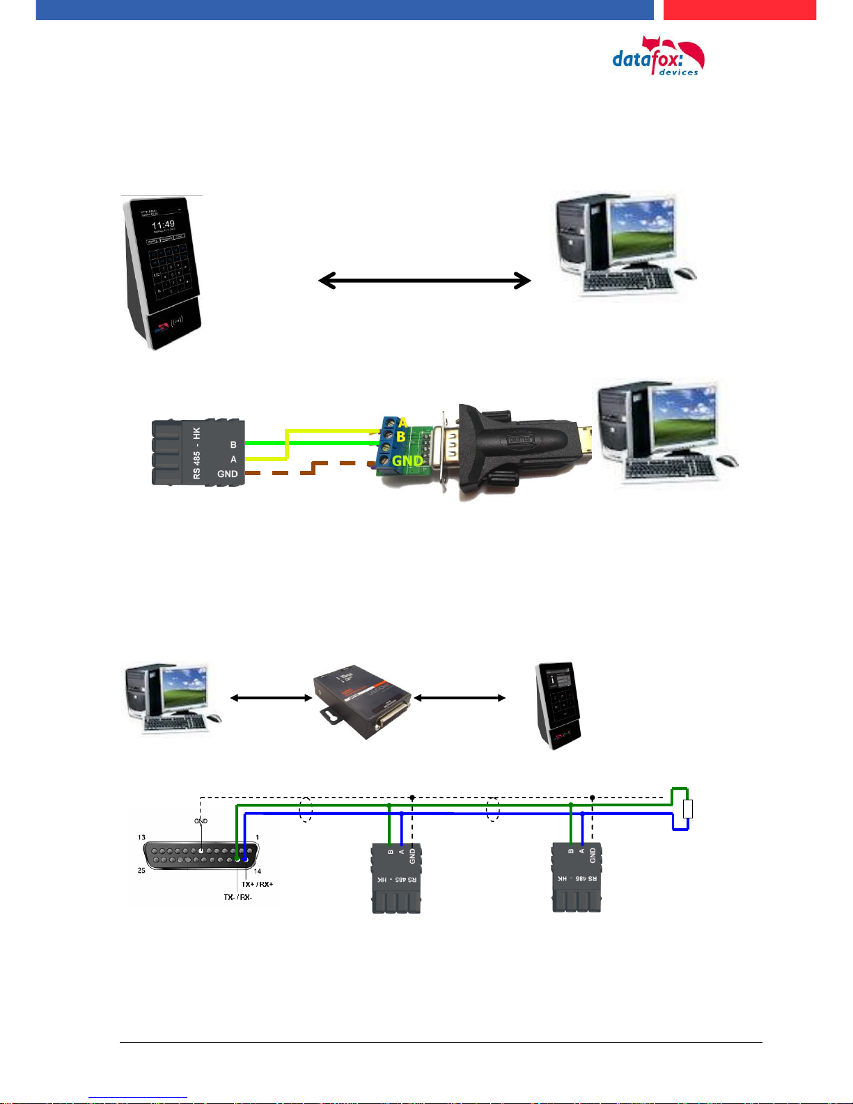
Manual Datafox Evo 4.3 Page 63 Date: 27.12.2017 V 04.03.09.XX
5.6.8. Communication via RS485
5.6.8.1. Connecting the termina via RS485 to PC
5.6.8.2. Connecting the Terminal via RS485 with a Comserver Lantronix
RS 485 to PC
up to 1000m
120 Ohm
plugr 4 Pol.
BUS A
BUS B
Pin 1 - GND
plug 4 Pol.
BUS A
BUS B
Pin 1 - GND
plug
Pin 15 - BUS B
Pin 14 - BUS A
Pin 7 - GND
TCP/IP
RS485
RS 485 Anschluss
am Terminal
USB - RS485
Adapter am PC

Manual Datafox Evo 4.3 Page 64 Date: 27.12.2017 V 04.03.09.XX
ID
ZM
TM
RefLocation
RefAction
PINGeneral
Reader
1
ID
RefGroup
RefTime
RefTimenoPin
Location
3
ID
Weekdays
TimeStart
TimeEnd
Time
4
Day
RefGroup
RefTime
Holiday
5
ID
Group
PIN
Menace
ActiveStart
ActiveEnd
ActiveGeneral
Identification
2
RefReader
PortIn
RefAction
RefTime
Event
6
ID
RefReader
PortOut
Elapse
RefTime
Action
7
5.7. connection and wirering of the accesscontrol
5.7.1. Configuration of Access control adn stuckture
The basis of the access control II are tables. They store all information about the hardware configuration of the access control system, access right of the employees, periods of time (activation,
blocking times, holidays,...). The tables are connected as follows:
The tables are created as text files. For an easier administration you can add comments within the
files.
When adding comments, you have to notice that in a comment line no field values can be given and
that the comment line has to start with a semicolon.
The table Reader.txt might look like this:
ID
ZM
TM
RefLocation
RefAction
PinGeneral
1 1 320 0 1 0 2 1 000 1 2
0
3 1 010 2 3
0

Manual Datafox Evo 4.3 Page 65 Date: 27.12.2017 V 04.03.09.XX
Holiday ControlIt is now possible for ZK-II to consider holidays at switching the relay. In order to
achieve compatibility with older versions, the function Consider Holidays for the Time Control of Relays has to be activated at the setup page Access Control 2. In the column Group, you specify the
Action ID of the switched relay output instead of a Group ID. Thus, it is not necessary to alter the
table structure of the holiday list. The column RefTime provides the time model applicable that day.
A minus sign must be inserted in front of the Action ID in order that the MasterIV terminal can differentiate between Action ID and Group ID. As a result, these Action IDs must be three-digit numbers.
Example:
Action
ID
RefReader
PortOut
Elapse
RefTime
1
10 1 25 0 2
11 1 25 0 3
12 1 0
0
Holiday
Day
RefGroup
„Action-ID“
RefTime
2012-05-01
1 3 2012-05-01
2 4 2012-05-01
-3
5
In the action list above, the door module with the ID 12 was assigned the time model 2 which
switches port 1 of the module. If separate holiday control has been activated in the setup, time
model 2 is not applied to the relay output at May 1, 2012, but time model 5.
Extended Parameterization ZK-II
The value range of the parameter 'ActiveGeneral' has been extended by the value 8. Additionally to
the general permission (value 9), a PIN request is executed - if defined so for the user and activated
for the reader. Furthermore, at both configurations of the ID cards with the ActiveGeneral value 8
and 9, the validity period of the ID card is checked.
For ZK-II the operation modes online, offline or online/offline after time-out are available. In online
mode, configuration lists stored in the device are not considered. A data record is read from the
server, analyzed and an action triggered. In offline mode, the configuration lists of the terminal are
used to grant or deny access to a person. Online / offline after time-out is a combination. If the server is unavailable, the terminal can decide on basis of its lists whether to grant access to a person or
not.

Manual Datafox Evo 4.3 Page 66 Date: 27.12.2017 V 04.03.09.XX
Timing of the Digital Outputs for the MasterIV Device Series:
It is possible to time the digital outputs of the MasterIV device series via tables. Thus, for example
turning down the heating system at night, a buzzer control and much more can be realized.
The following tables must be configured:
► Action
► Reader
► Time
Description:
Each action that is to be activated must be entered in the table Action. The table Action refers to the
tables Reader and Time. In the table Reader the module is provided on which the relay or the Open
Collector is to be switched. The reference to the table Time indicates when the switch is to be done.
If start and stop time are entered, the relay is switched on when exceeding the start time and
switched off when exceeding the stop time. The entry of the duration Elapse in the table Action is
ignored. If the relay is only to be activated for a few seconds, e.g. for a buzzer control, the stop time
has to be set on "‘00 : 00"’. If the start time is exceeded, the respective output will be switched for X
seconds (RefTime in Action table). The entry Elapse in the table Action now indicates the on-time.
Example:
► A buzzer is to be activated for 3 seconds from Monday to Friday at 10.00 am and 4 pm
(16.00). The buzzer is controlled by the internal relay of the PZE-MasterIV.
► The heating system is to be set to the "‘day mode"’ at 07.00 am and to the "night mode" at 7
pm (19.00) on all weekdays. The corresponding relay is at the door module with the bus
number 2.
Reader.txt
ID
ZM
TM
RefLocation
RefAction
PinGeneral
1 1 320
0 0 0 2 1
020
0 0 0
Time.txt
ID
Weekdays
TimeEnd
TimeEnd
3
12345
10:00
00:00
4
12345
16:00
00:00
5
1234567
07:00
19:00
Action.txt
ID
RefReader
PortOut
Elapse
RefTime
6 1 1
15 3 7 1 1
15 4 8 2 1 0 5

Manual Datafox Evo 4.3 Page 67 Date: 27.12.2017 V 04.03.09.XX
5.7.2. Description of Tables for Access Control 2
Name
Data type
Length
Description
ID
Number
(int)
4
Unique Key (value>0) of the Reader table.
ZM
Number
(int)
4
In our example, it has number 1. If there are several PZE-MasterIVs in an access system, they can be depicted in one table connection and it is not necessary to have a separate string for each PZE-MasterIV.
TM
Number
(int)
3
Contains two information in one number. Both figures on the left (010) indicate
the bus number of the door module, the figure on the right (010) contains information about the type of connection. A 0 means a connection via RS485, a 1
stands for a connection via RS232 as stub.
RefLocation
Number
(int)
4
Indicates which room is supervised by the reader.
RefAction
Number
(int)
4
Indicates which action is worked through after a successful check.
PinGeneral
Number
(int)
8
Can contain a numerical sequence by which a person without a card gets access.
Table Reader (List of all devices installed in the system)
Name
Data type
Length
Description
ID
Text
(ASCII)
20
Contains the ID card no. which is read at the TMR33 device or terminal. An ID
card can occur several times (is assigned to several authority groups).
Group
Number
(int)
4
Assigns the ID card to an authority group.
Pin
Number
(int)
8
Activates a PIN request if not equal 0. Please note that a PIN must not start
with zero. 0815 would be invalid.
Menace
Number
(int)
4
Activates (if not equal 0) a "‘menace-PIN"’ that can be added to the PIN. If entered, the system sends a data record that can be analyzed by software developed for this purpose and sets off the alarm.
ActiveStart
Text
(Date)
10
The tag entered here indicates the start date of the validity of the ID card.
(for example 2007-07-12 = yyyy-mm-dd)
ActiveEnd
Text
(Date)
10
The tag entered here indicates the end date of the validity of the ID card. (for
example 2007-07-12 = yyyy-mm-dd)
ActiveGeneral
Number
(int)
1
Activates or deactivates this card record.
0 = card blocked
1 = card active
2= virtual card (use only via DLL)
3 = access only by entering the PIN
8 = general authority (with PIN request)
9 = general authority (no PIN request)
Table Identification (list of all devices installed in the system - master and door modules)
Name
Data type
Length
Description
Day
Text
(Date)
10
Date of the blocking day. (form: YYYY-MM-DD)
RefGroup
Number
(int)
4
Indicates the authorization group to which the blocking day is applied. Zero defines a global validity for all groups.
RefTime
Text
(Time)
4
Indicates the assigned time model. (0 = not used) During this time access is
granted. Thus, also "‘half holidays"’ like New Year’s Eve can be realized.
Table Holiday (setting blocking days like holidays or company holidays)

Manual Datafox Evo 4.3 Page 68 Date: 27.12.2017 V 04.03.09.XX
Identifier
Data type
Length
Description
ID
Number
(int)
4
ID of the room. All other tables refer to this data line via this number, if necessary.
RefGroup
Number
(int)
4
Reference to the identification table. Labels the access authorized group. All
cards of this group have access to this room.
RefTime
Number
(int)
4
The time model in which authorized persons get access. (0 = not used)
RefTimeNoPin
Number
(int)
4
The time model for which entering an additional PIN is not necessary (at peak
times etc.).
Table Location (defines which card groups get access to which room at which time)
Name
Data type
Length
Description
ID
Number
(int)
4
ID of the time model. All other tables refer to this data line via this number, if
necessary.
Weekdays
Number
(int)
7
Indicates the weekdays on which the following period of time should be applied
(form: 7 digits at most 1-7 e.g. 134567 = Monday, Wednesday till Sunday)
TimeStart
Text
(Time)
5
The start point for the period of time. (form: 24h HH:MM)
TimeEnd
Text
(Time)
5
The end point for the period of time.
Table Time (grouping of single time zones (weekday from to) as a time model number)
Name
Data type
Length
Description
RefReader
Number
(int)
4
Module (door module or master) where the digital input is.
PortIn
Number
(int)
1
Number of the digital input on the module.
RefAction
Number
(int)
4
Reference to the action that should be carried out (e.g. switch relay).
RefTime
Number
(int)
4
The time model which indicates when the digital input is checked. (0 = not
used).
Table Event (assigning an action to a signal at the digital input)
Name
Data type
Length
Description
ID
Number
(int)
4
Action number, it can occur several times due to several actions that have to be
worked through.
RefReader
Number
(int)
4
Module (door module or master) on which an output(relay) is switched.
PortOut
Number
(int)
1
Indicates the number of the output on the module.
Elapse
Number
(int)
3
The duration of the switching of the relay (0 = permanently). Unit 200 ms
RefTime
Number
(int)
4
The time model indicates when the output may be switched. (0 = not used)
Table Action (list of all workable actions in the access control system; an action group, i.e. all actions with the same action number, can switch several relays)
5.7.3. Access control II with PHG-Modules

Manual Datafox Evo 4.3 Page 69 Date: 27.12.2017 V 04.03.09.XX
If the device MasterIV is used for access control, door
supervision or remote monitoring, one device can supervise up to 8 doors and control 12 doors at most.
Flush-mounted: 81 x 81 x 11 mm (WxHxD)
Surface-mounted: 81 x 81 x 40 mm (WxHxD)
The VOXIO can be used with Legic or Mifare. It is available for in-wall or onwall mounting with or without keyboard. Each reader has a sabotage recognition, three lamps for visualizing the state and a buzzer for the acoustic signaling.
The following hardware is available to set up an access control with PHG modules. The devices can
be combined in different ways according to their hardware requirements.
EVO 4.3
VOXIO
Relino
Relino B
IO-Box
From firmware version of the access reader 69806D of the PHG readers the autologin function for
Mifare is supported. Here for 5 of the max. 6 keys can be used in the setup.
!
Attention:
Technical data for the PHG access modules can be found on the Datafox DVD or in
our download area. Please note the power consumption of the modules and the voltage
drop at long cable lengths.
The responsibility for calculating the maximum cable lengths lies with the installer.
50 x 50 x 43 mm (WxHxD)
The RELINO reader can be used with Legic or Mifare. It is available for in-
wall mounting. Each reader has three lamps for visualizing the state and a
buzzer for acoustic signaling.
51 x 48 x 22 mm (WxHxD)
The I/O box as equipment for the RFID wall reader or RELINO reader has
two digital inputs and two digital outputs. The I2C bus is used as interface.

Manual Datafox Evo 4.3 Page 70 Date: 27.12.2017 V 04.03.09.XX
5.7.3.1. Connecting of PHG-reader
In order to connect the PHG modules, please note the PHG documentation on the Datafox CD:
<Datafox-Geräte- Datafox-Zutritt-Module PHG *.pdf>
In the PHG documents for the single modules, the pin assignment and configuration via the DIP
switches are described. In order to carry out an access control with theEVO 4.3 the option "‘access"’
has to be integrated (Datafox art. no. 105201). The following figure shows the possibilities for connecting the PHG devices to a. The following figure shows the possibilities for connecting the PHG
devices to a EVO 4.3 for access control.
The bus number of the module is set via the DIP switches 1 - 4. The DIP switch 5 always must be
set to "ON". The DIP switches 6 and 8 always must be set to "OFF". With the DIP switch 7 = "ON"
the RS485 bus is terminated at the last module, otherwise always "‘OFF"’.
If a door-opener is to be controlled additionally via a relay, the IO-box must be used.
With the IO-box two digital outputs as relays are available.

Manual Datafox Evo 4.3 Page 71 Date: 27.12.2017 V 04.03.09.XX
floating relay
contact
I²C
max. 5 m
RS485
max. 1000 m
Reader
I/O-Box
Reader
I/O-Box
I2C max. 5m
ISTY 2x2x0,8
/
~
Connection example one door and I/O Box:
:
Power supply 12 V DC for reader
- + 3A

Manual Datafox Evo 4.3 Page 72 Date: 27.12.2017 V 04.03.09.XX
Connecting example with one door and without I/O-Box:
Wire plan:
Wire plan for Siedle access reader:
TCP/IP
RS485
Türöffner
Busadresse
max. 42 V; 2A
Power supply for door opener
+ -
+ - max. 42V; 2A
Power supply for door opener
Bus Nr. 1
Siedle-access reader
Power supply 12 V DC for reader
- + 3A

Manual Datafox Evo 4.3 Page 73 Date: 27.12.2017 V 04.03.09.XX
RS485 bus diagram for access control with 3 PHG- modules:
TCP/IP und
AC 100-230 V
I²C
max. 5 m
potential-free
contact for door
RS485
Reader
I²C
max. 5 m
potential-free
contact for door
RS485
I²C
max. 5 m
potential-free
contact for door
RS485
Reader
Reader
more reader
DIP-switch
setting
last reader
max. 1000 m
Last reader
end resistor
switch 7 -> on

Manual Datafox Evo 4.3 Page 74 Date: 27.12.2017 V 04.03.09.XX
Door opener
–
+ GND A B
further reader
supply
12V 3A/DC
I2C max. 5m
ISTY 2x2x0,8
/ ~
– / ~
I2C max. 5m
ISTY 2x2x0,8
/ ~
– / ~
I2C max. 5m
ISTY 2x2x0,8
/ ~
– / ~
Door opener
Door opener
Wire plan PHG-reader:
In any case, a protection circuit should be integrated when connecting the door-opener.
A fly back diode for DC and an RC element for AC.

Manual Datafox Evo 4.3 Page 75 Date: 27.12.2017 V 04.03.09.XX
Connecting the IO-Box:
Anschluss (ST1,2,3)
Klemme Nr.
Beschreibung
ST1
1
Relais 1 normaly close
2
Relais 1 common
3
Relais 1 normaly open
4
free
5
free
6
digital in 1 Signal
7
digital in 1 ground
ST2
1
Relais 2 normaly close
2
Relais 2 common
3
Relais 2 normaly open
4
free
5
free
6
digital in 2 Signal
7
digital in 2 ground
ST3
1 und 2
ground
3
U+ 8…..30V
4
SCL
5
SDA
ST 1 Circuit diagram
3 = “S“ normaly open
2 = “G“ common
1 = “Ö“ normaly close

Manual Datafox Evo 4.3 Page 76 Date: 27.12.2017 V 04.03.09.XX
5.7.3.2. Configuration
The access modules work with internal encryption. The key is stored in the DatafoxStudioIV but not
visible.
If no key is provided under "AES Key" (PHG only), the default key is used.
!
Caution:
The key must only be changed at a fully installed access control. If you changed the key
and forgot it, the modules must be sent in. Restoring the default key is subject to a
charge.
All door modules that are compiled in the reader table have to be available in the RS485 network in
order to guarantee that the code can be changed in all modules if a new setup with a different code
is loaded. If a door module from the list in the bus is missing, the key is not changed. The old setup
with the old key has to be reloaded; otherwise, after rebooting the device, it is not possible to communicate with the door modules until the right key is used again.

Manual Datafox Evo 4.3 Page 77 Date: 27.12.2017 V 04.03.09.XX
If a defective reader is replaced by a new reader that has not been used yet, it is recognized by the
firmware automatically at the start and the encryption is set up. The reader can also be replaced
during operation, the firmware automatically integrates it.
Contrary to GIS readers, PHG readers always have 2 digital inputs and a sabotage contact. The
firmware regards input 1 and input 2 as normal inputs with the number 1 and 2 and the sabotage
contact as number 3. The sabotage contact is integrated in the reader. The PHG reader has no analog-switch-input for door monitoring.
Additionally, the PHG reader can be extended by an IO box. The IO box has two digital inputs and
two relay outputs. The IO box is accessed via the same address like the reader. The two digital inputs have port number 4 and 5, the digital outputs port number 1 and 2. In case of discontinuity or
sabotage, port no. 6 is used.
PHG modules and firmware:
All configurations like tables etc. are to be configured in the same way as for the access readers of
the TS series.
Only exception:
The IO box is not specified in the reader table. Thus, information regarding the modules which are
connected via the I2C bus, is omitted.
Corresponding reader table:
ID
ZM
TM
RefLocation
RefAction
PinGeneral
Description
1
320 1 0 1 0
Master device
2
010 1 1 1 0
Reader at RS485
(PHG)
3
011 1 1 1 0
IO-Box at I2C-Bus
4
020 1 2 2 0
Reader at RS485
(LTM)
5
021 1 2 2 0
IO-Box at I2C-Bus
If you want to use the PHG
modules, you have to set it in
the Additional Options.
After changing over to the access readers of the PHG series,
the firmware must be transferred again.
The device then selects the respective firmware from the
DFZ-file.

Manual Datafox Evo 4.3 Page 78 Date: 27.12.2017 V 04.03.09.XX
If the device MasterIV is used for access control, door
supervision or remote monitoring, one device can supervise up to 8 doors and control 12 doors at most.
diensions: 81 x 81 x 19 mm (BxHxT)
The EVO acceess reader can be used with 125 kHz, Legic or Mifare.
It is available for in-wall or on-wall mounting with or without keyboard. Each reader has a sabotage recognition, three lamps for visualizing the state and a buzzer for the acoustic signaling.
Signals from the backlight:
white permanent = Reader found an ready
white flashing = reader not found and not connection to the master
Signals from the backlight:
green = access accept
Signals from the backlight:
red = access denied or the master configured the read-
er currently.
5.7.4. Access control wiht EVO-access modules
The following hardware is available to set up an access control with EVO-modules. The devices can
be combined in different ways according to their hardware requirements.
EVO 4.3
EVO-access-reader
IO-modul for EVO-Access reader
Display
Backlit transponder symbol
3-coloured white, green, red
Individualization
Integrated backlight
Individual printable front glass with backlight 56 x 37mm
Colour always like transponder symbol
power supply
10 - 30V DC, max. 120mA
Environment values
Ambient temperature, Protection
-20 ° C to +70 ° C, IP65
Transponder systems
125kHz
Mifare
Legic
Hitag 1+2+S
Mifare Classic
Legic prime
Unique EM4102
Mifare Desfire
Legic advant
Titan EM4450
Mifare Ultralight
DGND
D IN1
Relay

Manual Datafox Evo 4.3 Page 79 Date: 27.12.2017 V 04.03.09.XX
Connectors of EVO-reader:
DIP-switch:
switch number
Off
On
1 – address Bit 0
+ 0
+ 1
2 – address Bit 1
+ 0
+ 2
3 – address Bit 2
+ 0
+ 4
4 – address Bit 3
+ 0
+ 8
5 – terminate resistor 120 ohm
not activ
activ
example
5-4-3-2-1
address 2, with terminate resistor
1-0-0-1-0
address 3, without terminate resistor
0-0-0-1-1
pin
Number.
description
1
+10V bis +30V DC ! neu
2
RS 485-Data „B“
3
RS 485-Data „A“
4
GND ground
DIP-switch
Connector for IOmodul
Relay + digital in

Manual Datafox Evo 4.3 Page 80 Date: 27.12.2017 V 04.03.09.XX
5.7.4.1. Connecting of the EVO-access reader examples
Cable plan for one door, 1 Relay in the EVO 4.3:
Reader Tabelle, for this example:
ID
ZM / Bus-ID
TM (Busadresse)
RefLocation
RefAction
PinGeneral
Beschreibungstext
1 1 010 1 1
0
Reader on RS485 Modulplace 1 = Bus ID 1
4 1 320 0 1 0 access-Box V4 (Masterdevice)
Wire plan for one access reader EVO:
TCP / IP (LAN)
M1
SIM
12VDC
USB
GPRS
GPS
RS232
M7
LAN
M8
485-A
485-B
12V
GND
M3
M2
DGND
D IN1
Relais
ZK
485-A
485-B
HK
Variante mit RS485 Haupt-
kommunikation
RS 485 ZK Bus-ID 1
Bus Nr. 1
Bus Nr. 1
Türöffner Relais 1 der ZK-Box
12V vom Master
+ - max. 30V; 2A
Power supply for door opener
Bus Nr. 1
EVO-access reader
Connector 4 pole
for Access Bus
connector 5 pole
for digital in and
out

Manual Datafox Evo 4.3 Page 81 Date: 27.12.2017 V 04.03.09.XX
5.7.5. Access control II with EVO-ZK-Plus-reader
5.7.5.1. Display and operation
The reader has a capacitive touch.
All images displayed by the reader and marked as standard below can be exchanged.
Display:
The entire display area is backed
by a touch screen.
With the DatafoxStudioIV, images
can be stored here for a gallery
display and for the necessary inputs/outputs.
See -> Configuration-> Display Designer.
Reading range of the transponder
with backlight in RGB colours.
The control of the LED is controlled exclusively by the readers
firmware.
access denied = red access permitted = green Bios activated = blue -

Manual Datafox Evo 4.3 Page 82 Date: 27.12.2017 V 04.03.09.XX
5.7.5.2. Display for state of acces control
Currently there are 2 displayed states for:
granted access: access denied:
5.7.5.3. Display the number keypad
If an additional PIN is requested for access, the keypad will be displayed automatically. For access
only by entering a PIN, it is sufficient to briefly touch the display to activate the PIN display.
5.7.5.4. Errormessage
Datafox standard image
Datafox standard image
Datafox standard image
Picture 1 of the gallery
error
communication
The reader is in constant communication with the master.
If communication is interrupted, this
is indicated by the text "Communication error" on the reader.
Antippen
Datafox standard image
PIN normal
Datafox standard image
PIN randomization

Manual Datafox Evo 4.3 Page 83 Date: 27.12.2017 V 04.03.09.XX
The following information can be called up in the general configuration:
- Installed firmware, serial number
- Memory allocation for the image memory
- Transponder test for the transponder configured in the master setup.
5.7.5.5. Bios-menu
Connect the reader to the 12V power supply with the connecting cable.
As soon as it is started, connect the reader via USB to a PC or a small battery (power bank).
The Bios menu can only be accessed when the USB port is powered.
Tap both top left and bottom right at the same time.
5.7.5.6. General configuration
USB
Power bank USB
USB port on the back of the
reader

Manual Datafox Evo 4.3 Page 84 Date: 27.12.2017 V 04.03.09.XX
The bus terminating resistor of 120 Ω is switched on or off in
the bus configuration under "Terminating resistor".
Note: If it is the last or only reader in the RS485 bus, the termi-
nating resistor must be switched on.
The bus address is defined in the bus configuration under
"Bus number" .
Note that only bus addresses between 1 and 16 are possible.
The input of the bus number is confirmed with the "Enter"
key (bottom right).
With the Escape button (bottom left) the process can be
aborted.
5.7.5.7. Display configuration
The following parameters can be set in the display configuration:
- the brightness of the device
- random number keys - arrangement of the pin and keyboard
- the basic activation of the pin - keyboard
5.7.5.8. Bus configuration
In the bus configuration, the initial parameters that are used
for the setup of the reader must be set, configured.
5.7.5.9. Setting the bus adress of the reader for RS485 bus
5.7.5.10. Activate the resistor for the end

Manual Datafox Evo 4.3 Page 85 Date: 27.12.2017 V 04.03.09.XX
Anschluss an den
4poligen ZK-Bus
Stecker:
5.7.5.11. Connection of the EVO-Access reader plus
On the backsite is a multicore cable.
The connection as fallows:
Nr.
Farbe
Funktion
1
Rot
+12V Power Input (10 - 30V DC)
2
Blau
GND Power Input
3
Gelb
RS485 - B
4
Grün
RS485 - A
I/O-Erweiterung
Nr.
Farbe
Funktion
5
Weiß
Relais gemeinsam
6
Braun
Relais Schließer
7
Grau
Relais Öffner
8
Violett
DigIn
9
Schwarz
DigIn - GND
Gehäuse
Aufbau
Front aus Alu mit gehärtetem Echtglas, kapazitivem Touch,
Gehäuserückwand Kunststoff: PC-ABS
Abmessungen (Breite x Höhe x Tiefe)
85 mm x 208 mm x 27 mm, ca. 20mm zusätzlich in UP-Dose
Gewicht
Basisgerät 550g zzgl. Wandhalterungsblech
Anzeige
LCD
TFT: 320 x 480 Pixel, active area 49,0 x 73,4 mm mit LED-Backlight
Beleuchtetes Transpondersymbol
3-farbig weiß, grün, rot
Tasten
Art, Größe
Tastatur über kapazitivem Touch-Display, Touchfläche 73,4 x 49,0mm,
Individualisierung
Individuelle Grafiken
Benutzeranzeigen über Grafiken individuell definierbar
Integriertes Leuchtfeld
Individuell bedruckbare Frontscheibe mit Beleuchtungsfeld 56 x 37mm
Farbe immer wie Transpondersymbol
Stromversorgung
10 - 30V DC, max. 500mA
Montage
Edelstahl-Montageplatte, Leser wird eingehängt und gesichert.
Umgebungswerte
Umgebungstemperatur, Schutzart
-20 °C bis +70 °C, IP65
Kommunikation
RS485-Schnittstelle, phg_crypt, 16 Busadressen und Abschluss Widerstand über Menü einstellbar
Sabotagesensor
Sabotageerkennung über Abstandserkennung zur Wandhalterung
Optionen
Türmodul
Erweiterungsmodul mit Relais (Umschalter) und einem digitalen Eingang
Diese Erweiterung sollte nicht im ungesicherten Bereich eingesetzt werden.
Transponder Leseverfahren
125kHz
Mifare
Legic
Hitag 1+2+S
Mifare Classic
Legic prime
Unique EM4102
Mifare Desfire
Legic advant
Titan EM4450
Mifare Ultralight
Spannungsversorgung 12 – 30 V
- +

Manual Datafox Evo 4.3 Page 86 Date: 27.12.2017 V 04.03.09.XX
Verkabelungsplan für 1 Türen, 1 Relais in dem EVO 4.3:
Entsprechende Reader Tabelle, Beispiel:
ID
ZM / Bus-ID
TM (Busadresse)
RefLocation
RefAction
PinGeneral
Beschreibungstext
1 1 010 1 1 0 Leser an RS485 Modulplatz 1 = Bus ID 1
4 1 320 0 1 0 ZK-Box V4 (Mastergerät)
Empfohlene Verdrahtung für einen Busanschluss mit einem EVO-Leser-Plus:
Alternativ kann bei der Verwendung von nur einem Leser dieser an die Spannungsversorgung des
RS485 Moduls aus dem Master genutzt werden.
Leser Typ
L in m
Strom in mA
Strom bei Start in mA
gf. Ergänzungen
Legic
50
iA
iA
Mifare
100
iA
iA Unique
100
iA
iA
TCP / IP (LAN)
M1
SIM
12VDC
USB
GPRS
GPS
RS232
M7
LAN
M8
485-A
485-B
12V
GND
M3
M2
DGND
D IN1
Relais
ZK
485-A
485-B
HK
Variante mit RS485 Haupt-
kommunikation
10-30V DC
+ - max. 42V; 2A
Versorgungsspannung für Türöffner
Bus Nr. 1
EVO-ZK-Leser-Plus
Stecker 4 polig
für ZK-Bus
Stecker 5 polig
für ZK-Bus
RS 485 ZK Bus-ID 1
Bus Nr. 1
Türöffner Relais 1 des Master Gerätes
Spannungsversorgung
12 – 30 V - +
Maximale empfohlene Länge = L
mit 0,25 mm
2

Manual Datafox Evo 4.3 Page 87 Date: 27.12.2017 V 04.03.09.XX
Verkabelungsplan für 3 Türen, 3 Relais in dem EVO 4.3:
Entsprechende Reader Tabelle, Beispiel:
ID
ZM / Bus-ID
TM (Busadresse)
RefLocation
RefAction
PinGeneral
Beschreibungstext
1 1 010 1 1 0 Leser mit Bus Nr. 1
2 1 020 2 2 0 Leser mit Bus Nr. 2
3 1 030 3 3 0 Leser mit Bus Nr. 3
4 1 320 0 1 0 (Mastergerät)
TCP / IP (LAN)
M1
SIM
12VDC
USB
GPRS
GPS
RS232
M7
LAN
M8
485-A
485-B
12V
GND
M3
M2
DGND
D IN1
Relais
ZK
485-A
485-B
HK
Variante mit RS485 Haupt-
kommunikation
RS 485 ZK
Bus Nr. 1
Türöffner Relais 1
Spannungsversorgung
für Türöffner.
Schaltleistung:
max. 42V; 2A
max.2,5 m
bis Abzweig
max.2,5 m
bis Abzweig
Spannungsversorgung
12 – 30V DC pro Leser 500mA
max.2,5 m
bis Abzweig
Türöffner Relais 2
Türöffner Relais 3
Bus Nr. 2
Bus Nr. 3

Manual Datafox Evo 4.3 Page 88 Date: 27.12.2017 V 04.03.09.XX
Verdrahtungsplan für 3 Türen, 3 Relais in dem EVO 4.3:
M1
SIM
12VDC
USB
GPRS
GPS
RS232
M7
LAN
M8
485-A
485-B
12V
GND
M3
M2
DGND
D IN1
Relais
ZK
485-A
485-B
HK
Variante mit RS485 Haupt-
kommunikation
Bus Nr. 1
Spannungsversorgung 12 – 30 V + -
+ - Spannung für Türöffner
Bus Nr. 2
Bus Nr. 3
max. 2,5m
weitere Leser möglich
max. 2,5m
max. 2,5m

Manual Datafox Evo 4.3 Page 89 Date: 27.12.2017 V 04.03.09.XX
5.7.6. Access control with TS-Readers
The following hardware is available to set-up access control with TS TMR33 modules. The different
options can be combined with each other according to the hardware requirements of the single devices.
EVO 4.3
Opening module (TS TMR33-TM)
72 x 72 x 40 mm
Reader (TS TMR33-L)
80 x 80 x 25 mm
Reader and Opening Module (TS TMR33-LTM)
80 x 80 x 25 mm
Note:
The single modules are connected to a bus. DIP switch 5 sets whether the modules are to
communicate via RS232 or RS485.
The MasterIV device supports the opening of up to 8 doors.
The door module is offered as pure electronic component e.g. to build it in a
padres box, or in a housing for surface mounting with alarm control panel.
The reader can be ordered separately to connect it directly to a PC or another
access check. A connecting diagram and a description of the commands for
the activation are included.
The module set can be ordered separately to connect it directly to a PC or another access check. A connecting diagram and a description of the commands
for the activation are included.

Manual Datafox Evo 4.3 Page 90 Date: 27.12.2017 V 04.03.09.XX
5.7.6.1. Installation Variants
A Door without a Separate Reader
The EVO 4.3 is access scanner, access master and door-opener at the same time. This solution
should only be used in protected areas so that the door opening relay cannot be manipulated.
.
RS232/485
TCP/IP
GSM/GPRS
WLAN
!
Caution:
The installation and connection of the TMR33 module may only be carried out by a qualified specialist. Avoid switching the connecting terminal (reverse polarity).
Relay to the door
Digital input for door
monitoring
+ -
max. 42V; 2A
power supply for door opener

Manual Datafox Evo 4.3 Page 91 Date: 27.12.2017 V 04.03.09.XX
A Door with a Separate Reader
The EVO 4.3 is installed in a protected area inside a building and the reader is installed outside. The
terminal is access master and door-opener at the same time. The door opening relay is in the PZEMasterIV and thus installed in the protected area. The access identification captured by the reader
is transferred to the EVO 4.3 and analyzed by it. If access is permitted, the door is opened via the
relay in the .
Installation plan:
This ver- sion is used frequently and can be installed easily and economically
as shown in the figure above.
Wiring plan:
:
Reader table for this example
ID
ZM
TM
RefLocation
RefAction
PinGeneral
Description
1 1 320 0 1 0 Access master
2 1 010 1 1 0 Reader on RS485 (L)
RS232/485
TCP/IP usw.
RS485 connection max. 1000 m
Relay to the door
Dorr monitoring
Reader (L)
Art-Nr.:106020
Power: max 30 V 2A
door opener
Reader module (L)
Art-Nr.:106020

Manual Datafox Evo 4.3 Page 92 Date: 27.12.2017 V 04.03.09.XX
Several External Doors via RS485 Bus
Here, a door module has to be used so that the door opening relay is within the protected area.
Installation plan:
Wire plan:
Reader (L)
Art-Nr.:106020
RS232 connection max. 15 m
Relay for door
Door control
RS232/485
TCP/IP usw.
RS485 connection
max. 1000 m
RS232 connection max. 15 m
Relay for door
Door control
12V + -
Reader (L)
Art-Nr.:106020
max. 30V 2A
door opener
max. 30V 2A
door opener
Reader (L)
Art-Nr.:106020
Door
control
Door
control

Manual Datafox Evo 4.3 Page 93 Date: 27.12.2017 V 04.03.09.XX
Several Internal Doors via RS485 Bus
The combined reader + door-module is used here. The door opening relay is included in the combined module. Caution: This assembly must not be used at outdoor locations because then the relay
is not within a protected area.
Installation plan:
Wire plan:
Button, for door opening from inside
RS232 connection max. 15 m
Relay for door
Door monitoring
RS232/485
TCP/IP usw.
RS485 connection
max. 1000 m
Relay for door
Door monitoring
Door – contact
Door monitoring
12V + -
Reader and door modul (LTM)
Art-Nr.:106030
ext. max. 30V 2A
Door opener
Reader and door modul (LTM)
Art-Nr.:106030
Door – contact
Door monitoring
ext. max. 30V 2A
Door opener
Button, for door opening
from inside

Manual Datafox Evo 4.3 Page 94 Date: 27.12.2017 V 04.03.09.XX
Interlocking Function with RS485 Bus
The combined reader + door-module and the reader-module is used here.
Installation plan:
Corresponding reader table:
ID
ZM
TM
RefLocation
RefAction
PinGeneral
Description
1
320 1 0 1 0
Master on bus RS485
2
010 1 1 1 0
Reader and relay on RS485 (LTM)
3
011 1 1 1 0
Reader on RS232 (L)
4
020 1 2 2 0
Reader and relay on RS485 (LTM)
5
021 1 2 2 0
Reader on RS232 (L)
6
030 1 3 3 0
Reader and relay on RS485 (LTM)
7
031 1 3 3 0
Reader on RS232 (L)
RS232/485
TCP/IP usw.
RS485 connection
max. 1000 m
Relay for door
Door monitoring
RS232 connection max. 15 m
RS232 connection max. 15 m
Relay for door
Door monitoring
RS 485
Max.1000 m
LTM
Art-Nr.: 106030
Bus adress: 3
Bus adress: 2
Bus adress: 1
RS232 connection max. 15 m
Relay for door
Door monitoring
RS232 Verbindung max. 15m
Relais zum Türöffner
Türüberwachung
RS232/485
TCP/IP usw.
RS485 Verbindung
max. 1000m
Relais zum Türöffner
Türüberwachung
 Loading...