


Handbuch
Datafox EVO 3.5 Pure
Flexible data collection with method

Handbuch Datafox EVO 3.5 Pure Seite II Datum: 06.08.2018 Version: 04.03.07.XX
© 2018 Datafox GmbH
This document has been created by Datafox GmbH and is copyrighted against third parties. Datafox
GmbH considers all contained information, knowledge and depictions as its sole property. All rights,
including also translation, reprint or copy of the whole document or parts of it, require written consent of Datafox GmbH.
The assertion of all rights in this respect is reserved to Datafox GmbH, especially in case of the
grant of a patent. The handover of this documentation does not establish a claim to the license or
the use of the soft- and hardware. Copies of the floppy disks and CDs may only be made for the
purpose of data backup. Every unauthorized copy of this documentation or the Datafox software will
be prosecuted.
Handbuch Datafox EVO 3.5 Pure Seite III Datum: 06.08.2018 Version: 04.03.07.XX
Alternations
Alternation in this Dokument
Date
Chapter
Discription
06.08.2017
all
Revision the manual to new version 04.03.10.xx
Alternations of the version
With the device generation IV a new versioning scheme has been introduced. According to this
scheme the file name of the device firmware and the setup program (DatafoxStudioIV) is composed
as follows:
Product name
XX.
Device generation
YY.
Compatibility
(which versions
can be used together)
ZZ.
Version number
(functional extension)
Build
Troubleshooting
(with a new version
the Build number is
reset)
z. B. AE-MasterIV
04.
03.
9.
04
The use of the manual depends on the version of the firmware and the DatafoxStudioIV or the
DFComDLL. Gather from the following table which manual matches which version. For different
combinations no support can be offered.
Firmware StudioIV and DLL validity
Firmware: 4.03.09.xx.
Studio: 4.03.09.xx
Dll: 4.03.09.xx
The DatafoxStudioIV is backward compatible. This means that you can configure a device with a
newer DatafoxStudioIV also older firmware, the device only supports the natural functions that are
implemented in the older firmware version. Ie, relevant to the functions that are possible, is always
the manual state that the firmware associated with the Setup equivalent. It is not possible to provide
a centering firmware configured with a stand of DatafoxStudioIV to who is older than the firmware.
recommendation:
If possible, use always the current version of DatafoxStudioIV.
What features are supported in which software versions, is from the file:
Datafox MasterIV, SW version xxx.pdf list as shown.
The file is located on the Datafox DVD and for download on the homepage. Please also note the
instructions in each chapter in the manual. The updates are available on our website under
www.datafox.de download.

Handbuch Datafox EVO 3.5 Pure Seite IV Datum: 06.08.2018 Version: 04.03.07.XX
Inhalt
1. For you Safty 1
2. introduction 2
2.1. Structure of the Documentation ............................................................................... 2
2.2. Guarantee Restriction ............................................................................................... 2
2.3. Typography of the Documentation ........................................................................... 3
2.4. Important General Notes ........................................................................................... 3
3. Intended Use and Environmental Protection 5
3.1. Regulations and Notices ........................................................................................... 5
3.2. Power supply ............................................................................................................. 5
3.3. Environmental Influences ......................................................................................... 5
3.4. Mounting outdoors .................................................................................................... 6
3.4.1. Degree of protection .................................................................................................... 6
3.5. Temperature ............................................................................................................... 6
3.6. Repair ......................................................................................................................... 7
3.7. Cleaning ..................................................................................................................... 7
3.8. Further Notices .......................................................................................................... 7
3.9. Disposal ..................................................................................................................... 8
4. System Requirements / Hardware 9
4.1. System Structure ....................................................................................................... 9
4.2. Requirements for Operating Datafox Devices ......................................................... 9
4.3. Kompatibilität Compatibility ................................................................................... 10
4.3.1. Firmware File Archive (*.dfz) ...................................................................................... 10
4.3.2. Datafox Devices and Device Firmware ...................................................................... 10
4.3.3. Device Firmware and Device Setup ........................................................................... 10
4.3.4. Device Firmware and Communications DLL .............................................................. 11
4.3.5. Communications DLL and DatafoxStudioIV ............................................................... 11
4.3.6. DatafoxStudioIV and Device Setup ............................................................................ 11
4.3.7. Update / Downgrade .................................................................................................. 12
5. Device 13
5.1. Commissioning ........................................................................................................ 13
5.2. Guidline for Commissioning ................................................................ ................... 13
5.2.1. Set-up of the device ................................................................................................... 13
5.2.2. Installation of the Device ............................................................................................ 14
5.2.3. Troubleshooting during Commissioning ..................................................................... 14
5.3. Operation and display elements of the Evo 3.5 Pure ............................................ 15
5.3.1. Composition and Operation EVO 3.5 Pure................................................................. 15
5.3.2. Display setup and bios of the EVO-Line 3.5 Pure ...................................................... 16
5.3.2.1. Structure display "normal display" 2.8/3.5 .................................................................. 16
5.3.2.2. Structure Display EVO 3.5 /2.8 Pure "in the Bios menu ............................................. 17
5.4. Installation of the EVO 2.8 / 3.5 Pure Terminal ...................................................... 21
5.5. Connecting of EVO 2.8 /3.5 Pure Terminals ........................................................... 22
5.5.1. Connecting plugs ....................................................................................................... 22
5.5.2. Powersupply of the EVO 2.8 / 3.5 Pure ...................................................................... 23
5.6. Power via POE for 2.8/3.5 ........................................................................................ 23
5.6.1. Modules for devices of hardware V4 .......................................................................... 24
5.6.1.1. Description of the various extension modules ............................................................ 24
5.7. Read the optional placement of the device ............................................................ 24
5.7.1.1. Read out important module information from the device ............................................ 26
5.7.1.2. Connection of the individual modules ......................................................................... 28
5.7.1.3. Analog inputs, 4 times analog IN ............................................................................... 28
5.7.1.4. 2 times digital out ....................................................................................................... 29

Handbuch Datafox EVO 3.5 Pure Seite V Datum: 06.08.2018 Version: 04.03.07.XX
5.7.1.5. 1 time digital Out 1x digital IN .................................................................................... 29
5.7.1.6. 4 times digital IN ........................................................................................................ 29
5.7.1.7. RS-485 bus for access control ................................................................................... 30
5.8. Communication of Hardware V4 Devices ............................................................... 31
5.8.1. Communication via USB ............................................................................................ 31
5.8.2. Automatic dedected conectet USB to PC ................................................................... 32
5.8.3. Installing USB driver for Hardware V4 Devices .......................................................... 33
5.8.4. Comunication / record transfer via USB-Stick (Host) .................................................. 34
5.8.4.1. Error message by using USB-Stick (Host) ................................................................ . 35
5.8.5. Communication via TCP / IP ...................................................................................... 36
5.8.5.1. Communication TCP / IP via network-cable ............................................................... 37
5.8.5.2. Communication TCP / IP via wLAN / Wifi ................................................................... 38
5.8.5.3. Location selection in the Bios menu WLAN ................................................................ 40
5.8.5.4. Recommended setting ............................................................................................... 40
5.8.5.5. Connection of the Terminals via TCP/IP DNS / DHCP ............................................... 41
5.8.6. Communication via RS485 ....................................................................................... 44
5.8.6.1. Connecting the termina via RS485 to PC .................................................................. 44
5.8.6.2. Connecting the Terminal via RS485 with a Comserver Lantronix ............................... 45
5.8.7. Communication via Cellular Network (GPRS) ............................................................ 47
5.8.7.1. Communication state ................................................................................................. 48
5.8.8. Communication via SMS ............................................................................................ 49
5.8.8.1. Send a SMS .............................................................................................................. 49
5.8.8.2. Receive SMS ............................................................................................................. 50
5.9. connection and wirering of the accesscontrol ...................................................... 53
5.9.1. Configuration of Access control adn stuckture ........................................................... 53
5.9.1.1. Description of Tables for Access Control 2 ................................ ................................ 55
5.9.2. Access control II with PHG-Modules .......................................................................... 58
5.9.2.1. Connecting of PHG-reader ........................................................................................ 59
5.9.2.2. Configuration ............................................................................................................. 65
5.9.3. Access control wiht EVO-access modules ................................................................. 67
5.9.3.1. Connecting of the EVO-access reader examples ....................................................... 69
5.9.4. Access control II with EVO-ZK-Plus-reader ................................................................ 70
5.9.4.1. Display and operation ................................................................................................ 70
5.9.4.2. Display for state of acces control ............................................................................... 71
5.9.4.3. Display the number keypad ....................................................................................... 71
5.9.4.4. Errormessage ............................................................................................................ 71
5.9.4.5. Bios-menu ................................................................................................................. 72
5.9.4.6. General configuration ................................................................................................ 72
5.9.4.7. Display configuration ................................................................................................. 73
5.9.4.8. Bus configuration ....................................................................................................... 73
5.9.4.9. Setting the bus adress of the reader for RS485 bus ................................................... 73
5.9.4.10. Activate the resistor for the end ................................................................................. 73
5.9.4.11. Connection of the EVO-Access reader plus .............................................................. 74
5.9.5. Access control with TS-Readers ................................................................................ 78
5.9.5.1. Installation Variants ................................................................................................... 79
5.9.5.2. Connecting the TS-series access reader ................................................................... 85
5.9.6. Online funktions for the access control ...................................................................... 88
5.9.6.1. Online via http-protocoll ............................................................................................. 88
5.9.6.2. Online via DLL connection ......................................................................................... 91
5.9.7. Function extention for access control II ...................................................................... 92
5.9.7.1. General description .................................................................................................... 92
5.9.7.2. Examples ................................................................................................................... 92
5.9.7.3. Description of the table „Action2" ............................................................................... 96
5.9.7.4. Additional Functions for Access Control ..................................................................... 97
5.9.7.5. Liste Presence ........................................................................................................... 98
5.9.8. State message off access control .............................................................................. 99

Handbuch Datafox EVO 3.5 Pure Seite VI Datum: 06.08.2018 Version: 04.03.07.XX
5.9.9. Funkcionfor access control U&Z (locking cylinders) ................................................. 103
5.9.9.1. Design example ....................................................................................................... 103
5.9.9.2. First start with locking cylinders ............................................................................... 105
5.9.9.3. Montage und Demontage der Zylinder ..................................................................... 105
5.9.9.4. Set up the wireless network for cylinder ................................................................... 106
5.9.9.5. Battery state and live time ........................................................................................ 107
5.9.9.6. change the access control master ID and nob Active Time ...................................... 108
5.9.9.7. Optical and acoustic signals of the U&Z locking cylinder .......................................... 109
5.9.9.8. Supported transponder technologies ....................................................................... 110
5.10. RFID Reader ........................................................................................................... 111
5.11. Data on Card .......................................................................................................... 112
5.11.1. General infomations ................................................................................................. 112
5.11.2. Settings for using DataOnCard ................................................................................ 113
5.11.3. DataOnCard on the access control reader ............................................................... 117
5.11.4. DataOnCard an a aceess control reader - wirering .................................................. 118
5.12. Operation Finger Scanner ..................................................................................... 119
5.12.1. General infomation .................................................................................................. 120
5.12.2. Teach-In .................................................................................................................. 122
5.12.3. Procedure ................................................................................................................ 123
5.12.4. Process Variants...................................................................................................... 124
5.12.5. Technical Data of the Fingerprint Module ................................................................ 125
5.13. Barcode Reader ..................................................................................................... 126
6. Technical specifications EVO 2.8 /3.5 Pure 128
7. FAQ 128
8. Index 129
Handbuch Datafox EVO 3.5 Pure Seite 1 Datum: 06.08.2018 Version: 04.03.07.XX
1. For you Safty
Safety Information for Datafox Products
The EVO 3.5 Pure must only be operated according to the instructions
given in the manual.
Do no insert any foreign objects into the openings and ports.
The device must not be opened. All maintenance work must only
be performed by authorized specialists.
Some devices contain a lithium ion battery or a lithium battery.
Do not throw into fire!
Achtung! Supply voltage: 12 Volt DC
Siehe jeweiliges Typenschild / technische Daten.
See respective type label / technical data.
The device must only be operated with a power-limited power supply
according to EN 60950-1. If you do not observe these instructions,
the device may be damaged.
The following temperature ranges must be observed
Working area / storage temperature: -20° C bis +70° C
Mobile communications module: -20° C bis +55° C
In areas with cellphone ban, GSM, WLAN and other cellular modems
must be turned off.
Persons with heart pacemakers:
When using the device, maintain a distance of at least 20 cm between the
heart pacemaker and the device in order to avoid possible interferences.
Turn the device off immediately if interferences are assumed.
Protection class: Observe the technical data of the respective device.
In case of laser devices of class 2, the eye is protected by the blink reflex
and/or turning reactions if you briefly and accidentally look into the laser
beam. The devices may be used without further protective measures. Nevertheless, avoid looking directly into the laser beam of the laser scanner.
Observe the additional notes in the chapter,
“Proper use and environmental protection”
We declare under our sole responsibility that the product described fullfills the
protection requirements of European Directive 89/336 / EEC as amended by
91/236 / EEC, 92/31 / EEC, 93/97 / EEC and 93/68 /. See the manual of the
devices for the standards. Evidence is provided by compliance with the following standards:
- EN 55022 : 2006 + A1:2007
- EN 55024 : 2003
- EN 61000 – 6 – 2: 2005
- IEC 61000-3-2 : 2005 + A1:2008 + A2:2009
- IEC 61000-3-3 : 2008

Handbuch Datafox EVO 3.5 Pure Seite 2 Datum: 06.08.2018 Version: 04.03.07.XX
2. introduction
Datafox data terminals have been developed to fulfill the requirements of modern personnel time
recording where users have high demands concerning flexible and elegant design. Furthermore, the
Datafox Embedded-Concept also covers access control. All relevant data can be recorded with
modern technology and be transferred to the analysis software immediately. Billings, calculations or
other analyses can be performed in a timely manner; processes can be monitored and controlled
actively. This saves time and ensures the data quality and immediacy required.
Datafox data terminals are based on the Datafox Embedded-System which is equipped with modern
technology for data collection and of course also data transfer. You make your entries comfortably
via keyboard, touch display, RFID or barcode. The device is available with fingerprint, GPS, GSM,
GPRS, USB etc. It fulfills all conditions for a flexible usage not only for personnel or order time recording but also for further scopes. This constitutes a real added value. The powerful tools DatafoxStudioIV and DLL facilitate quick and easy integration in any IT solutions. Due to scalability, numerous options are available. You can select according to your company's requirements and only pay
what you really need.
2.1. Structure of the Documentation
The manual contains a change history as well as a general part with safety information, the introduction and information concerning system requirements and system structure.
The general part is followed by the main part of the manual. It contains the chapter Product Description Device. In this chapter, device-specific components are described as well as the device's functions.
The final part of the manual provides technical data about the device and a glossary whose purpose
it is to ensure a consistent understanding between user and manufacturer.
2.2. Guarantee Restriction
All installers are responsible for the use of the device and its accessories in accordance with its intended purpose and in compliance with the applicable laws, standards and directives.
All data in this manual has been checked carefully. Nevertheless, errors cannot be excluded. Therefore, we offer no guarantee nor accept any liability for consequences that derive from errors of this
manual. Of course we are grateful if you point out errors to us. We reserve the right to make modifications in respect of technical progress. Our general terms and conditions of business apply.
Note:
Due to DatafoxStudioIV, Datafox devices offer many functions and combinations of
functions not all of which can be tested in the case of updates. This applies especially to setups defined by you as customer. Before updating your device, please ensure
by tests that your individual setup works without any errors. If you encounter a problem, please inform us immediately. We will take care of the clarification of the problem on short notice.

Handbuch Datafox EVO 3.5 Pure Seite 3 Datum: 06.08.2018 Version: 04.03.07.XX
2.3. Typography of the Documentation
FW .................................................................. Abbreviation for firmware (software in the device)
SW ................................ .................................. Abbreviation for software
HW .................................................................. Abbreviation for hardware
GV ................................................................... Abbreviation for global variable
<Name;Software Version.pdf> ........................ File names
Note:
Useful information which helps you avoiding possible mistakes during the installation,
configuration and commissioning is given here.
!
!
Caution:
Here, notes are provided which must be strictly observed. Otherwise, malfunctions of
the system will occur.
2.4. Important General Notes
!
Caution:
Use the devices only according to regulations and follow the installation, commissioning and operating instructions. Installation and commissioning may only be performed by authorized specialists.
Subject to technical alterations.
!
Caution:
Due to technical development, illustrations, function steps, procedures and technical
data may vary slightly.
The Datafox device has been developed for the purpose of creating a flexible and easily integrated terminal for data recording serving for a great variety of applications. The device is robust
and easy to use. Due to the PC setup program, the device is quickly and easily configured for its
application field so that you save time.
Numerous optional features, such as bar code reader, transponder reader, digital inputs etc.,
enable you to use the device for:
PZE - Personnel time recording
AZE - Order time recording
BDE - Operating data recording (I/O-processing)
ZK - Access control
FZDE - Vehicle data recording / telematics
This manual describes the creation of setups with the setup program DatafoxStudioIV
without covering specific applications. Potential problems and difficulties are pointed
out.
This manual describes the functionality of the EVO 3.5 Pure and explains its characteristic features.
For example, installation, operation and equipment of the device are described.
In order to define the behavior of the device, a setup must be created. For this purpose, the DatafoxStudioIV has been developed.

Handbuch Datafox EVO 3.5 Pure Seite 4 Datum: 06.08.2018 Version: 04.03.07.XX
With some practice it will be possible to create a complete compilation for the EVO 3.5 Pure
within half an hour. If you need functions that are not available, please contact us.
Note:
If you need support for the compilation of setups, we offer you our services. Due to
our extensive experience with the setup, we work very quickly and can make your
setup even more efficient through useful advices, so that the input at the device can
be performed quickly and securely.
Note:
Due to DatafoxStudioIV, Datafox devices offer many functions and combinations of
functions not all of which can be tested in the case of updates. This applies especially to setups defined by you as customer. Before updating your device, please ensure
by tests that your individual setup works without any errors. If you still encounter
problems after thoroughly testing your setup, please inform us immediately. We will
fix the error on short notice.

Handbuch Datafox EVO 3.5 Pure Seite 5 Datum: 06.08.2018 Version: 04.03.07.XX
3. Intended Use and Environmental Protection
3.1. Regulations and Notices
According to the current state of the art, measures were taken to ensure that the device meets the
technical and legal regulations as well as safety standards. Nevertheless, malfunctions due to interferences through other devices can still occur.
Please observe local regulations when using the device.
3.2. Power supply
Only operate the device externally with a limited power source in accordance with EN 60950-1.
Connection voltage of the MasterIV devices: : 12 to 24 volts DC
If the devices run with rechargeable batteries, note the instructions in chapter "Rechargeable Bat-
tery".
!
Caution:
In the event of non-compliance with these instructions, the device or the battery (if
any) can be damaged or destroyed!
In order to ensure maximum battery life, it is recommended to recharge the battery only after complete discharge.
See respective type label of the device EVO 3.5 Pure.
3.3. Environmental Influences
Extreme environmental influences may damage or destroy the device and should be avoided. This
includes fire, extreme sunlight, water, extreme cold and extreme heat.
See respective type label of the device.
Handbuch Datafox EVO 3.5 Pure Seite 6 Datum: 06.08.2018 Version: 04.03.07.XX
3.4. Mounting outdoors
3.4.1. Degree of protection
The terminal device has IP54 on the front side.
On the backside, only the cable feed / connection area is a restriction with respect to the IP class. If
the device is mounted on a flat base, the connection area is protected so that the entire system has
IP65
3.5. Temperature
The device has an approved temperature range of - 20 ° C to + 70 ° C.
A heater is not necessary for outdoor use.
Due to the inherent heat of the electronics and power supply, the temperatures in the unit are higher
even at ambient temperatures below -20 ° C.
Condensation water only occurs when a cold object comes into the heat and would therefore only
be an issue for mobile devices.
We recommand, if you use the devices outsite, then let it running permanently. Both in terms of
temperature as well as condensation, it is recommended to not switch off devices which are used
outdoors.
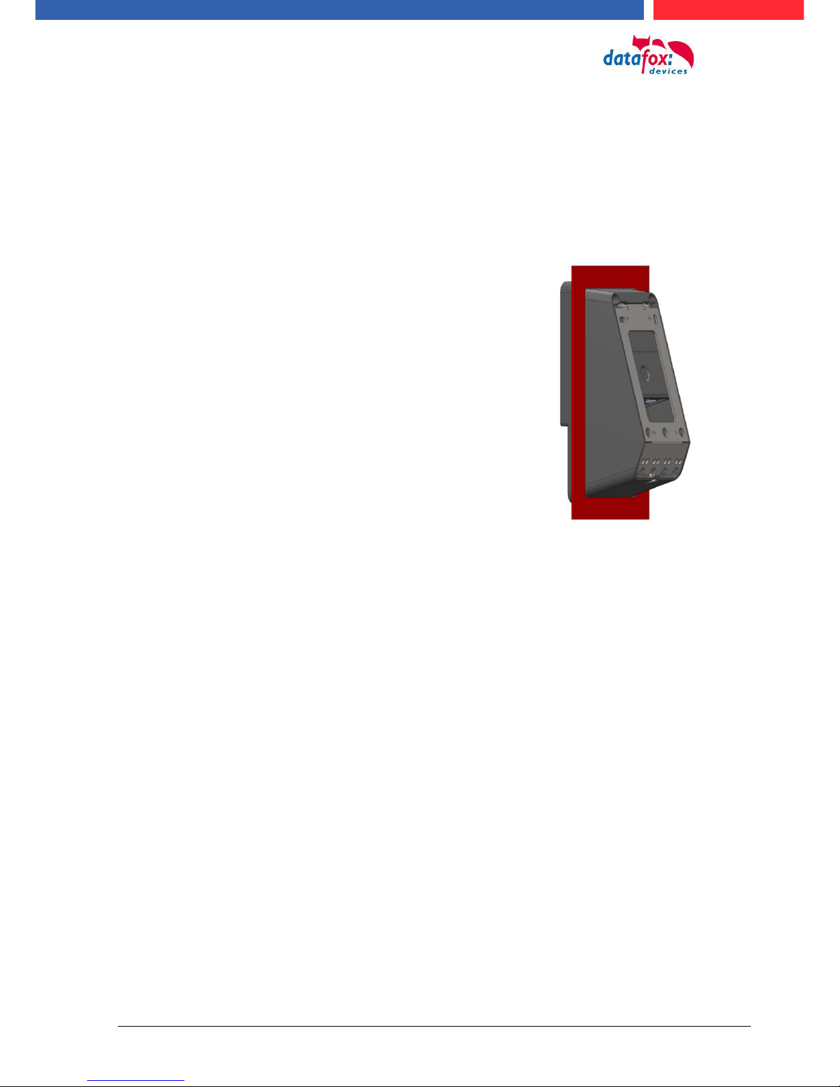
View recessed
Installation in
A front plate /
Mounting plate .
The connection area is set up to the top of the apparatus,
so that no water coming from above (e.g., rain) could
penetrate. Only jet water from below would be a problem.
Should additional conditions beyond the normal weather
cause the water to come from below, the terminals can
be sealed to the wall when mounting.
For the EVO terminals it is advisable to mount the units
on the heel of the front shell.
This would sink the entire back of the device with the
connections and in the inaccessible area.
In order to allow such mounting, a mounting surface must
be provided by the customer. For example, In boxes with
front panel.
In the case of bell systems / mailboxes / barriers, mounting plates are usually already available which can be
used for this purpose.
Handbuch Datafox EVO 3.5 Pure Seite 7 Datum: 06.08.2018 Version: 04.03.07.XX
3.6. Repair
Except for the battery replacement in mobile devices , Datafox devices are maintenance-free and
must only be opened by authorized professionals. In case of defects, please contact your dealer or
the Datafox service hotline.
If a definite defect is present, you can also send the device directly to Datafox.
3.7. Cleaning
CAUTION
Risk of explosion if batteries are replaced improperly.
Dispose used batteries according to the instructions.
3.8. Further Notices
Do not expose the device to strong magnetic fields, especially during operation.
Operate the slots and connections of the device only with the appropriate intended equipment.
Ensure that the device is secured during transport. For reasons of safety, do not use the device
while driving a vehicle. Also ensure that technical equipment of your vehicle is not compromised by
the device.
In order to prevent SIM card misuse, have your SIM card blocked immediately in cases of loss or
theft of the device.
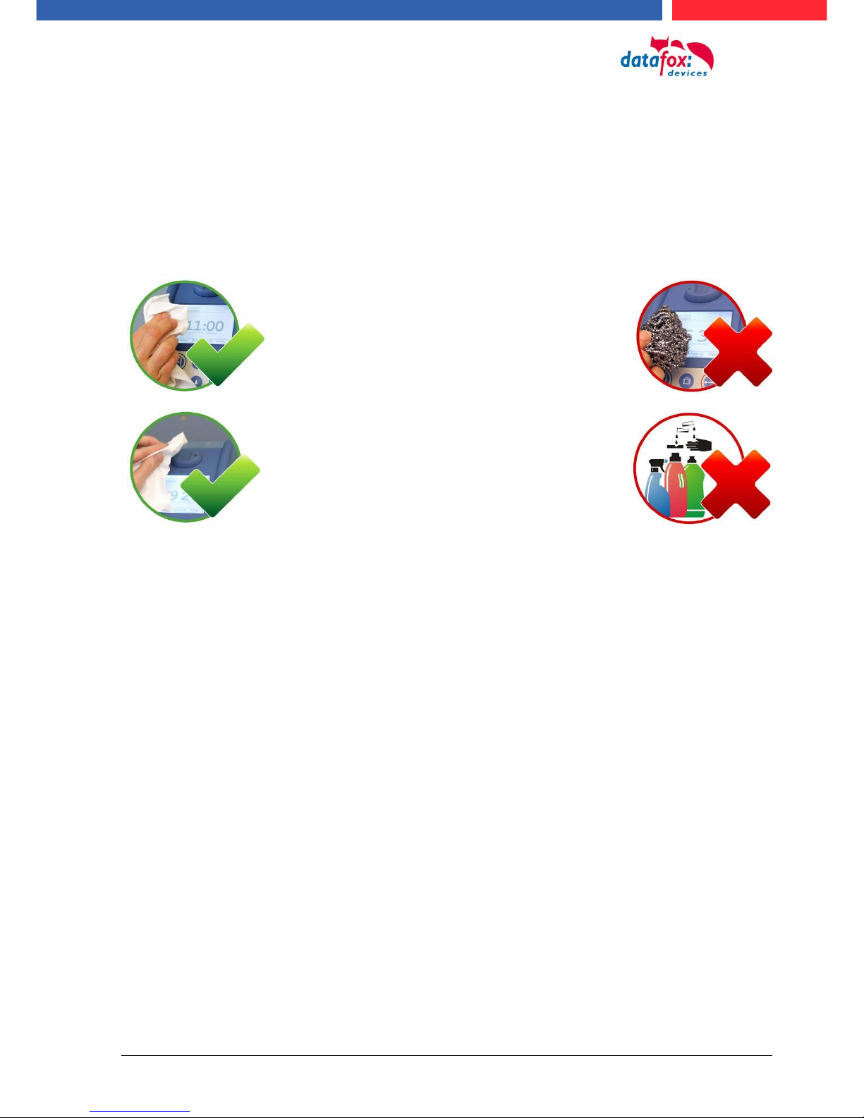
For the removal of smudges, espe-
cially on the display, the keypad and
the finger scanner, please only use
a dry or very damp cloth.
Never use a scrubbing solution or
acidic cleaner.

Handbuch Datafox EVO 3.5 Pure Seite 8 Datum: 06.08.2018 Version: 04.03.07.XX
3.9. Disposal
Observe local regulations concerning the disposal of packaging material, used batteries and
scrapped electrical equipment.
This product complies with the EU Directive No. 2002/95/EC, its appendices and the Council Decision laying down the restrictions of the use of hazardous substances in electrical and electronic
equipment.
The device is covered by the European Directive on Waste Electrical and Electronic Equipment
which came into force on February 13, 2003 and was translated into the legislation of the Federal
Republic of Germany on August 18, 2005.
Do not dispose the device in domestic waste!
As the user, it lies within your responsibility to dispose electrical and electronic equipment via the
designated collection facilities. The correct disposal of electrical and electronic equipment protects
human life and the environment.
For more information regarding the disposal of electrical and electronic equipment, please contact
your local authorities or waste disposal companies.
Handbuch Datafox EVO 3.5 Pure Seite 9 Datum: 06.08.2018 Version: 04.03.07.XX
4. System Requirements / Hardware
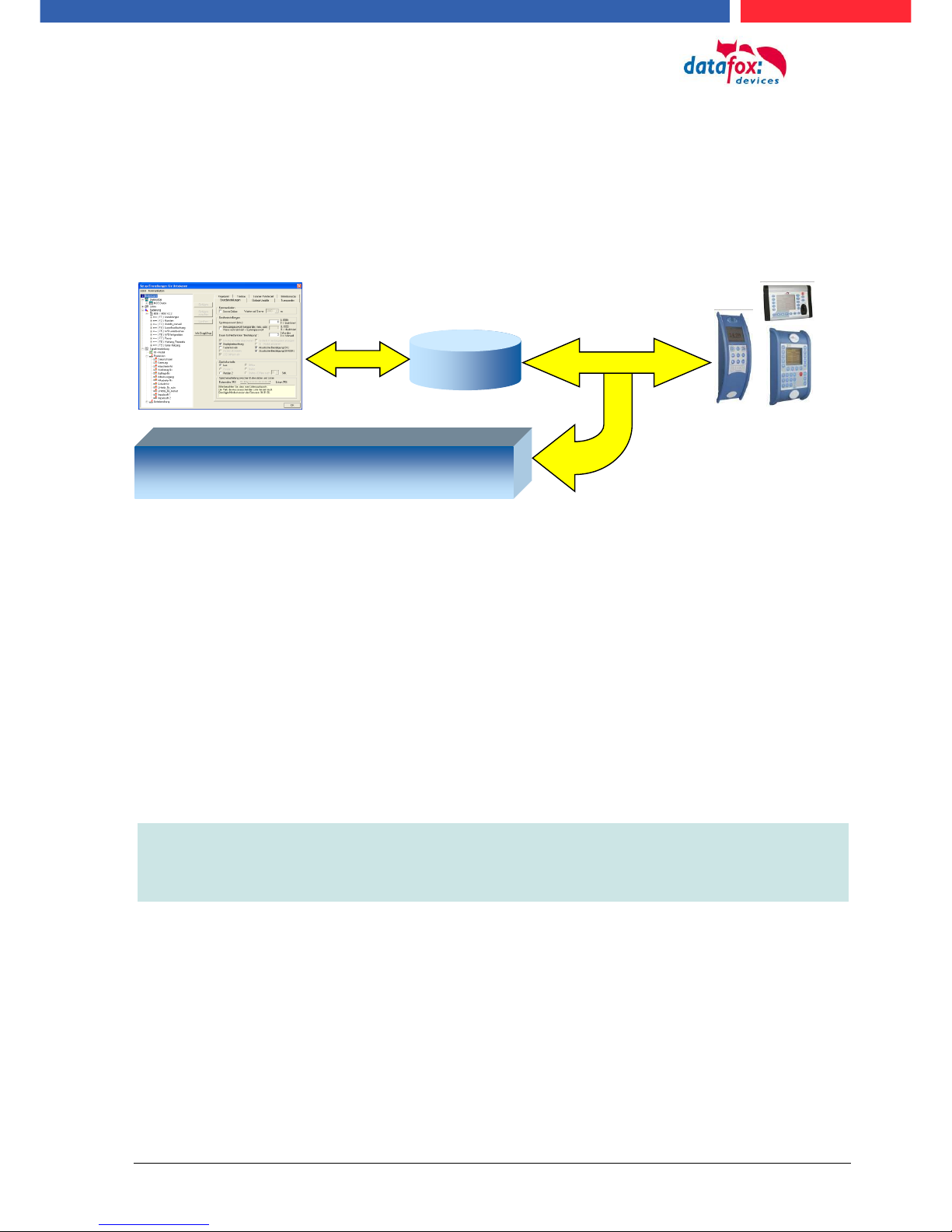
4.1. System Structure
The system consists of the Datafox device, the DatafoxStudioIV, the communication DLL and a
software for processing the generated data.
4.2. Requirements for Operating Datafox Devices
In order to operate the Datafox device, you need a 230 V power connection for the Datafox power
supply. Depending on the main communication set, you need a corresponding transfer medium or
connection cable.
Main communication:
USB > one standard USB-A toUSB-mirco Cable (see the chapter connection USB).
RS485 > a transmission path in accordance with the EIA-485 standard (see Connection
RS485).
GSM/GPRS > a distortion-free mobile connection (see Connection GSM).
WLAN WiFi> a distortion-free channel to an access point (802.11 b/g) within reach (see
Connection WLAN).
at least one standard Ethernet cable, no „cross over“ (see Connection TCP)
HTTP(internet) via LAN > TCP/IP connection with free internet access. The data are sent
to a server.
Note:
With increasing demands on transfer rate and interference immunity, the demands
on the transmission path increase as well with regard to quality (interference immunity).
Setup
Create setup
Save setup
Transfer setup to device
Software for processing the generated data
DatafoxStudioIV
Communication- DLL

Handbuch Datafox EVO 3.5 Pure Seite 10 Datum: 06.08.2018 Version: 04.03.07.XX
4.3. Kompatibilität Compatibility
The compatibility must be observed urgently between:
- Datafox devices and the device firmware
- Device firmware and device setup
- Device firmware and communication DLL
- Communication DLL and DatafoxStudioIV
- DatafoxStudioIV and device setup
4.3.1. Firmware File Archive (*.dfz)
Description
Device files (*.hex) of the MasterIV devices are delivered in a common firmware file archive. It has
the file extension DFZ (stands for Datafox Zip). Now simply the firmware file archives (*.dfz) are indicated instead of the device files (*.hex). This applies to the DatafoxStudioIV and the DLL. The indication of device files (*.hex) is still possible.
Function of the Archive
The transfer routine of the device file selects the right file from the firmware file archive on the basis
of the hardware options available in the device. Thus, it is guaranteed that all hardware components
available in the device are supported by the corresponding firmware.
Manual Selection of a File
If you do not want to integrate the archive in your installation, you have the possibility to add single
device files from the archive to the installation.
The file format of the firmware file archive is ZIP. Hence, you can open the archive with every
standard ZIP-program. Via the entry "Open With" in the context menu you can select an appropriate
program for opening the file. If necessary, you can call up a program combined with this file format
to open the file by renaming the file from DFZ to ZIP.
In the archive you find a file named "Inhalt.pdf"; it contains information which file (*.hex) of the archive matches your device. Extract the desired device file (*.hex) and rename it if necessary. A renaming of a file is possible at any time, because all information are in the file itself.
You can state the device file extracted before as device file in DatafoxStudioIV and at calling the
DLL function. It is still tested if the file can be loaded into the chosen device before the transfer
takes place.
4.3.2. Datafox Devices and Device Firmware
Each Datafox device has an electronic flat module. The module has specific hardware equipment
concerning the options (e.g. mobile radio, WLAN, fingerprint,...). Due to technical conditions, different options are mutually exclusive. Currently, not all hardware options can be supported in one
firmware file due to limited program memory. This means that each device with specific hardware
options needs a proper firmware to support the hardware options by the software.
!
Caution:
Hardware generation V 3 is supported from version 04.02.00.x onwards. The DatafoxStudioIV is compatible up to and including firmware version 04.01.x.y. Older versions 04.00.x.y are not supported any more.
4.3.3. Device Firmware and Device Setup
The firmware (operating system) of the device and the device setup (*.aes data file = application
program) form a unit. By the device setup, the runtime behavior of the device (the firmware) is determined. This means the response of the device to input events by the user or the environment
(e.g. digital inputs). In principle, only those functions of the device are executed that are supported
by the firmware and defined via the setup. Prior to the productive commencement, you should there-

Handbuch Datafox EVO 3.5 Pure Seite 11 Datum: 06.08.2018 Version: 04.03.07.XX
fore test each setup with the corresponding device or on a device with the same hardware options
and firmware.
4.3.4. Device Firmware and Communications DLL
A firmware supports certain functions, dependent on the hardware options. The communication DLL
is the interface between the firmware and the DatafoxStudioIV or your processing software. Therefore, the firmware must always have the same or a lower version number as the communication
DLL.
Note:
If your application uses a newer version of the DLL than the firmware does, you can
only use functions that are supported by the firmware.
Otherwise, you will receive an error message (e.g. function not supported) which has
to be analyzed.
4.3.5. Communications DLL and DatafoxStudioIV
Note:
The DatafoxStudioIV and the communication DLL are developed and released as a
bundle. Therefore, they have to be used as a bundle.
A newer version of DatafoxStudioIV does not work with an older DLL.
4.3.6. DatafoxStudioIV and Device Setup
With the DatafoxStudioIV, you create a device setup (application program) for the Datafox device.
That means that in the setup only those functions were defined which were available in the DatafoxStudioIV version at the time of the setup creation. The DatafoxStudioIV you use for opening a
device setup may thus only be newer but never older than the DatafoxStudioIV version you used to
create the device setup.
Note:
The updates are always available for download on our homepage www.datafox.de.
!
Caution:
When new devices are delivered, the latest firmware is loaded on the devices. If you
wish to work with an older firmware version, please perform a downgrade. Please
observe the compatibility notes in the release notes of the respective firmware version.

Handbuch Datafox EVO 3.5 Pure Seite 12 Datum: 06.08.2018 Version: 04.03.07.XX
The data file <Device name>, Software Versionen Stand <version number>.pdf shows
which functions are supported by which software release.
You will find the file on the product CD. Please also follow the instructions given in the chapters
of the manual.
4.3.7. Update / Downgrade
A firmware update or downgrade is a very sensitive process. Possibly, a reset of the main
communication to RS232 may occur. In any case, consider the information regarding the
compatibility in the software version list.
Firmware Update
!
Caution:
Before starting a firmware update, please check on the basis of the software version
list whether there are any version dependencies that must be observed.
For example: when changing from Version 04.00.xx to version 04.01.xx, at least version
04.00.23.769 or higher must be present in order to run the update to version 04.01.xx successfully.
Firmware Downgrade
A firmware downgrade is not recommended.
We are constantly working towards improving the software/firmware; all functionalities are still included in new versions. New software always offers better functionalities and possible bugs are
fixed.
!
Caution:
When performing a firmware downgrade the firmware has to be transmitted to the
device twice. This has technical reasons. Errors shown on the display of the device
after the first transfer can be ignored.

Handbuch Datafox EVO 3.5 Pure Seite 13 Datum: 06.08.2018 Version: 04.03.07.XX
5. Device
Note:
It has to be taken care of a suitable protection from direct sunlight because the synthetic
materials are not 100% UV resistant. Fading simply is an optical defect which does not
restrict the function of the device.
!
Caution:
Pleas keep in mind that MasterIV terminals use a flash memory. According to the manufacturer each memory sector (512 byte) can be written to a maximum of 100,000 times.
The firmware of the terminals distributes the access to the memory sectors, this technique is called wear levelling. Bad blocks in case of write or read failures are not used
anymore. However, despite this technique it is not advisable to write the memory too
frequently. The application should initialize a new list transfer only after a change of the
list data but not cyclically.
Keep in mind the message - FlashService - in the display of the device. It
means that the live time of the flash memory according to the manufacturer
instruction will be reached soon. Then the device has to be sent to Datafox for
service.
5.1. Commissioning
On delivery, the device is fully functional and configured with a demo setup so that you can test the
input immediately. After establishing the power supply the device will switch on automatically. The
EVO 3.5 Pure automatically starts booting, recognition of the hardware options and loading the setup. After having finished booting, the device switches to operation. Now the EVO 3.5 Pure is ready
for use.
Note:
On delivery, the main communication is set to USB.
!
Caution:
If external modules (e.g. access control, signal processing via the digital inputs) with an
external power supply are used, ensure to comply with all limits (max. voltage and current) before commissioning the system.
5.2. Guidline for Commissioning
5.2.1. Set-up of the device
This section provides a short guideline for commissioning und links to the corresponding chapters in
the manual.
► Connecting device to current supply
► Setting interface for communication
► Loading setup of the device See manual „DatafoxStudioIV“

Handbuch Datafox EVO 3.5 Pure Seite 14 Datum: 06.08.2018 Version: 04.03.07.XX
5.2.2. Installation of the Device
► Installing the device at the intended location
► Establishing connections for:
o Power:
o Communication:
USB
TCP/IP (HTTP)
TCP/IP wlan
GPRS
RS485
o Digital inputs
o Digital outputs
o Analog inputs
o Access control
► Finishing installation of the device
► Setting for man communication
5.2.3. Troubleshooting during Commissioning
► Please see the FAQ on our website: http://www.datafox.de/faq-de.html.
► Tips:
o Connection to the device cannot be set up via TCP/IP
Check IP in the device and the application (studio)
Ping on IP
Setting "Active Connection" in BIOS? set to NO
Setting "HTTP" in BIOS? set to NO
Handbuch Datafox EVO 3.5 Pure Seite 15 Datum: 06.08.2018 Version: 04.03.07.XX
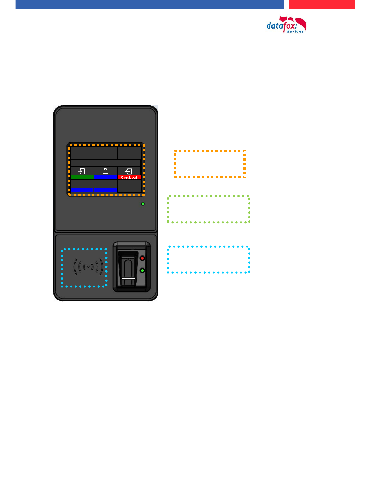
5.3. Operation and display elements of the Evo 3.5 Pure
5.3.1. Composition and Operation EVO 3.5 Pure
The terminal includes a capacitive touch.
he
read sector for
transponder
display and
touchsector
Power-LED
Signaled: Voltage connected
08:45
We. 26.06.13
Please choose
Check in
absent
Check in
balances
Order

Handbuch Datafox EVO 3.5 Pure Seite 16 Datum: 06.08.2018 Version: 04.03.07.XX
5.3.2. Display setup and bios of the EVO-Line 3.5 Pure
5.3.2.1. Structure display "normal display" 2.8/3.5
The entire display surface is provided with a touch. Just tap with your finger on the tile you want to
select.
Date Time corresponds to the system time of the device that is also used for the data records.
Number of records in memory (displays up to 99, thereafter 99+).
Communication tile with symbols for:
TCP /IP During active communication this symbol will be displayed,
o Wifi communication
Wifi is activated as the main communication
Wifi connected
Wifi communication active
o USB
o USB Host (save the data to USB - Stick)
o GSM with state display e.g.[30].
o GPRS with state display e.g. [33] please refer „state messages on display“.
cellular modem switched off
cellular modem switched on but no connection to the provider.
cellular modem switched on, active connection to the provider.
Indication on display
o In the main menu the header two of the setup is displayed.
o In menus and input chains, the header lines 3 and 4 from the setup are displayed.
o During the transmission of a setup or a firmware update, the device switch into a system stop
mode and displays this symbol „ system stop“ in this tile.
o Display in the left area of the tile:
= transponder input (take over value of transponder)
= check in
= check out
Tile for „ESC“ if needed
Tile for state and company logo.
The logo can be uploaded via the Studio IV.
-> configuration -> display designer
date
time
tile
Texts according to setup (header two) name of EK and
name of input box.
Function buttons according setup
15 buttons are possible an to main
page
08:45
We 26.06.13
i
Please choose
Check in
absent
Check out
balances
Order
Handbuch Datafox EVO 3.5 Pure Seite 17 Datum: 06.08.2018 Version: 04.03.07.XX
Mi 26.06.13
Enter Password
ESC
***-
1 2 3 0 4 5 6
7 8 9
08:45
Menu
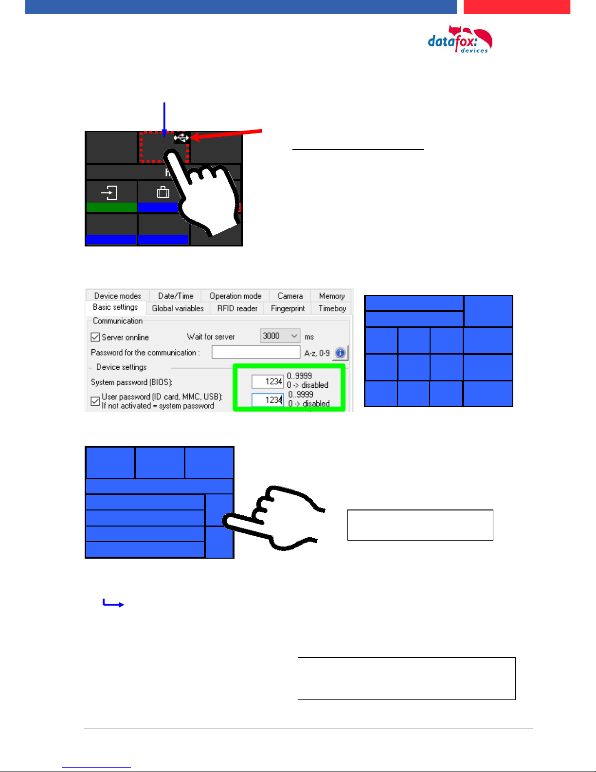
5.3.2.2. Structure Display EVO 3.5 /2.8 Pure "in the Bios menu
You get into the bios menu when you press the tile company logo for two seconds.
If a bios password is set, you are able to enter it here.
Display in Bios Menu:
General information:
Firmware Info
last message / no message available
transponder test
memory consumption
signal volume
provider
data storage 3068kB
list storage 1028kB
08:45
We 26.06.13
i
Please choose
Check in
absent
Check out
balances
Order
General Information
User Settings
System Menu Bios
ESC
The respective submenus should be selfexplanatory. The respective display depends
on the hardware equipment.
To select each menu, simply
tap on it with your finger.
Display of the status icons:
Tap the logo briefly to display the status icons.
You can also change the display of the icons in
the user settings to:
Constantly in place of the logo
Constantly in the "ESC" tile
For 60 seconds instead of the logo
off
Handbuch Datafox EVO 3.5 Pure Seite 18 Datum: 06.08.2018 Version: 04.03.07.XX
Menü
08:45
Communication
08:45
Lan-Parameter
IP
ESC
192.123.123.155
1 2 3 0 4 5 6 7 8 9
08:45
Lan parameters
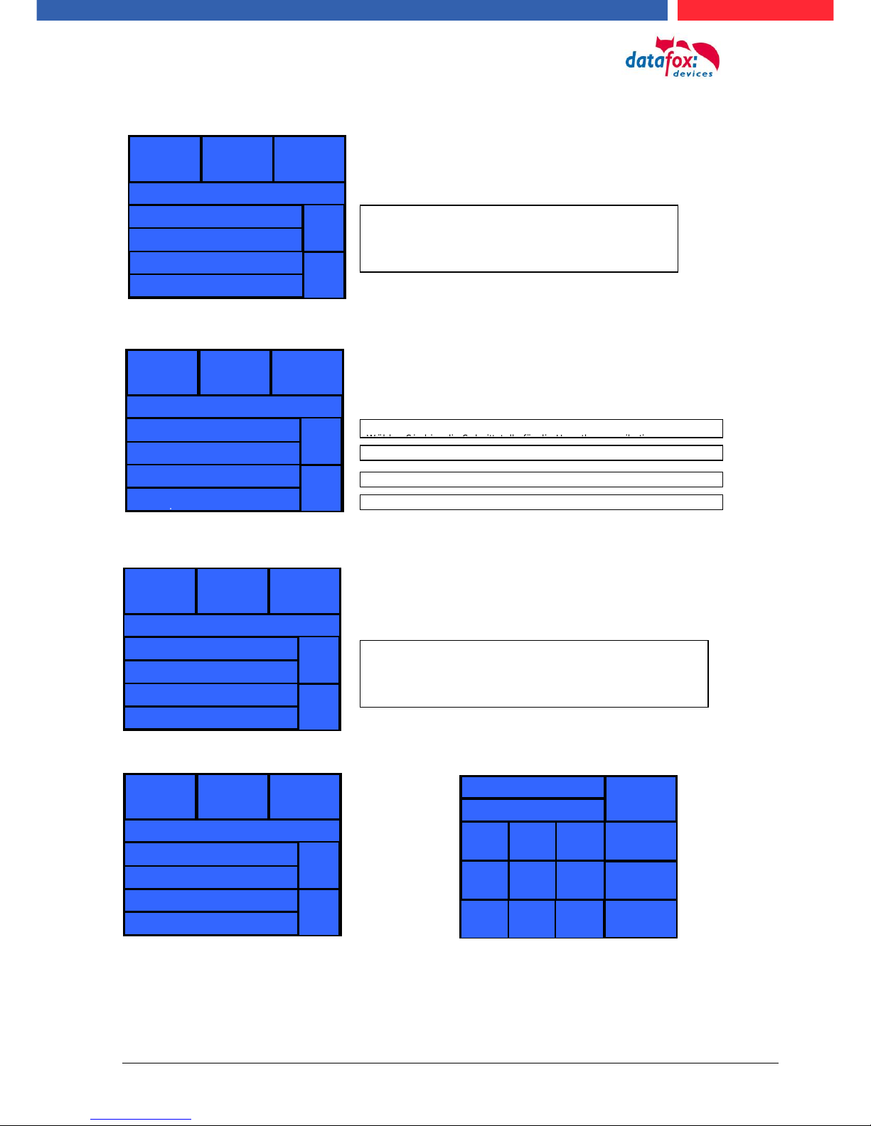
System Menu Bios:
set communication:
TCP / IP / DHCP - settings:
TCP / IP - settings: IP - set
The respective submenus should be selfexplanatory. The respective display depends
on the hardware equipment.
08:45
System Menu Bios
Firmware Info
System Info
Communication
Display/Signal Volume
ESC
Interface LAN
Active-Mode no
HTTP-Mode no
Lan-Parameters
ESC
Select here the interface for the main communication.
parameter for active-mode (standard = no)
parameter for HTTP (standard = no)
settings of the TCP/IP parameter (IP-address)
MAC E4:F7:A1:00:01:0C
DHCP no
IP 192.123.123.155
Netmask 255.255.255.000
ESC
< > < > <
>
If in the device DHCP (yes) is activated, you
aren´t able to change the IP-address.
The IP assigned by the server will be displayed.
Gateway 192.123.123.1
Port 8000
Reporting cycle (alive) 45
Handbuch Datafox EVO 3.5 Pure Seite 19 Datum: 06.08.2018 Version: 04.03.07.XX
08:45
Menu
08:45
Transponder menu
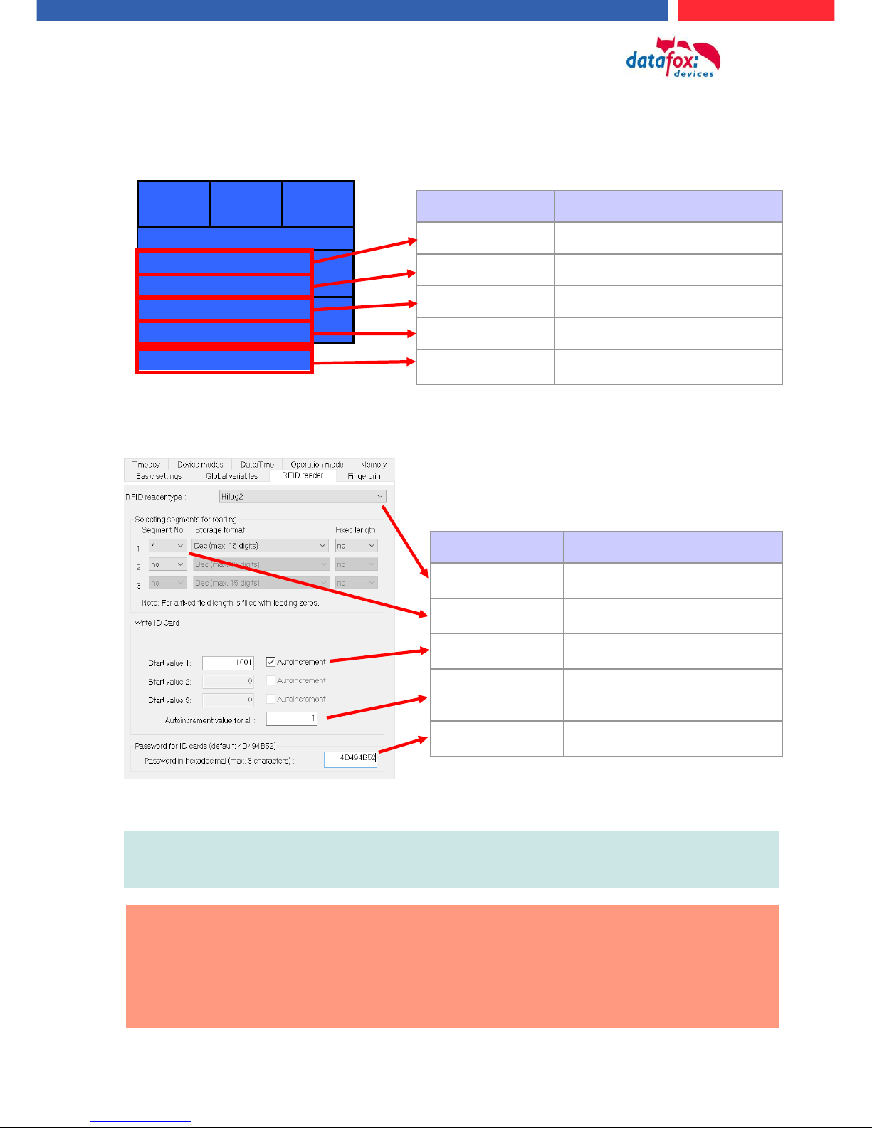
The transponder settings can also be set in the setup.
Some settings to write the transponders must be adjusted in the setup.
Note:
If IDs are to be written with a password,
the password must first be programmed on them.
!
Attantion:
In the setup a programmable transponder type and a programmable segment must be
set. Ex.:
- Hitag 2 -> from segment 4
- Mifare Classic -> from sector 0 block 1
Otherwise, only the type and version of the transponder reader will be displayed.
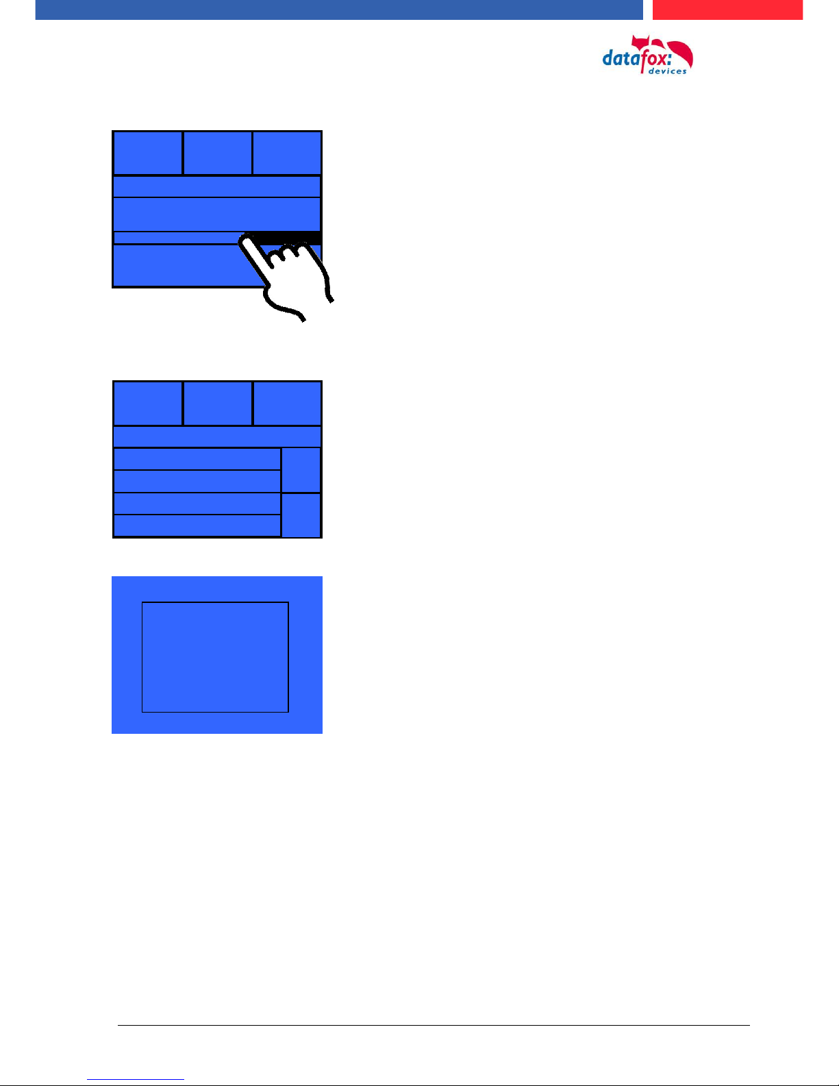
name
meaning
Transponder type
Type of the transponder reader
Version
version of the transponder reader
Write badges
Start writing
Increment
Auto increment
Segment4 => 1001
Start in the 4th segment with the
value you set.
name
meaning
transponder type
Here, the correct transponder
type must be specified
segment no.
In which segment should be
written / read
starting value
Defines the starting value of the
number to be programmed
autoincrement
When activated, the programming value always counts up
the final number
password
The password to write / read
the ID
Type gis ts-r32
Version V 2.06 PN 1092
Write Badges
Increment
Segment 4 1001
ESC
Handbuch Datafox EVO 3.5 Pure Seite 20 Datum: 06.08.2018 Version: 04.03.07.XX
08:45
07.03.14
Signal Volume
08:45
Touch
Signal volume:
Touch-Test:
This menu can be found under
„user settings“ -> „touch“.
This menu can be found under
"user settings" -> "display / signal volume".
-> "signal volume"
Just tap the bar in the middle to change the volume.
Test
Test
Here the correct function of the touch screen can be
checked.
To exit the menu, hold down on the display with two fingers
for three seconds.
Handbuch Datafox EVO 3.5 Pure Seite 21 Datum: 06.08.2018 Version: 04.03.07.XX
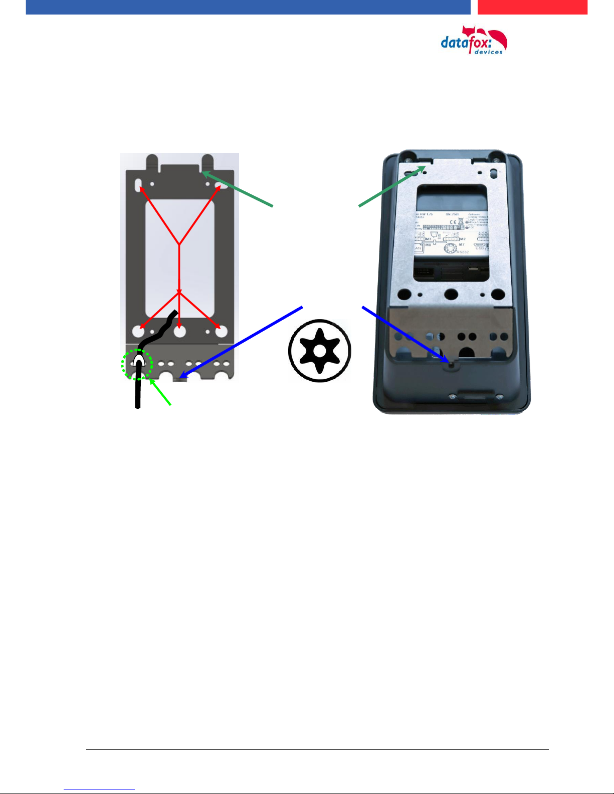
5.4. Installation of the EVO 2.8 / 3.5 Pure Terminal
The wall mounting takes place by means of a wall bracket. This is attached to the wall via 4 attachment points.
Fixed screw
The terminal is
mounted at the top.
On the down site
can you fixed the
terminal with a
screw.
Befestigungslöcher
Attachment for cable ties for
strain relief.
Torx T8
Handbuch Datafox EVO 3.5 Pure Seite 22 Datum: 06.08.2018 Version: 04.03.07.XX
5.5. Connecting of EVO 2.8 /3.5 Pure Terminals
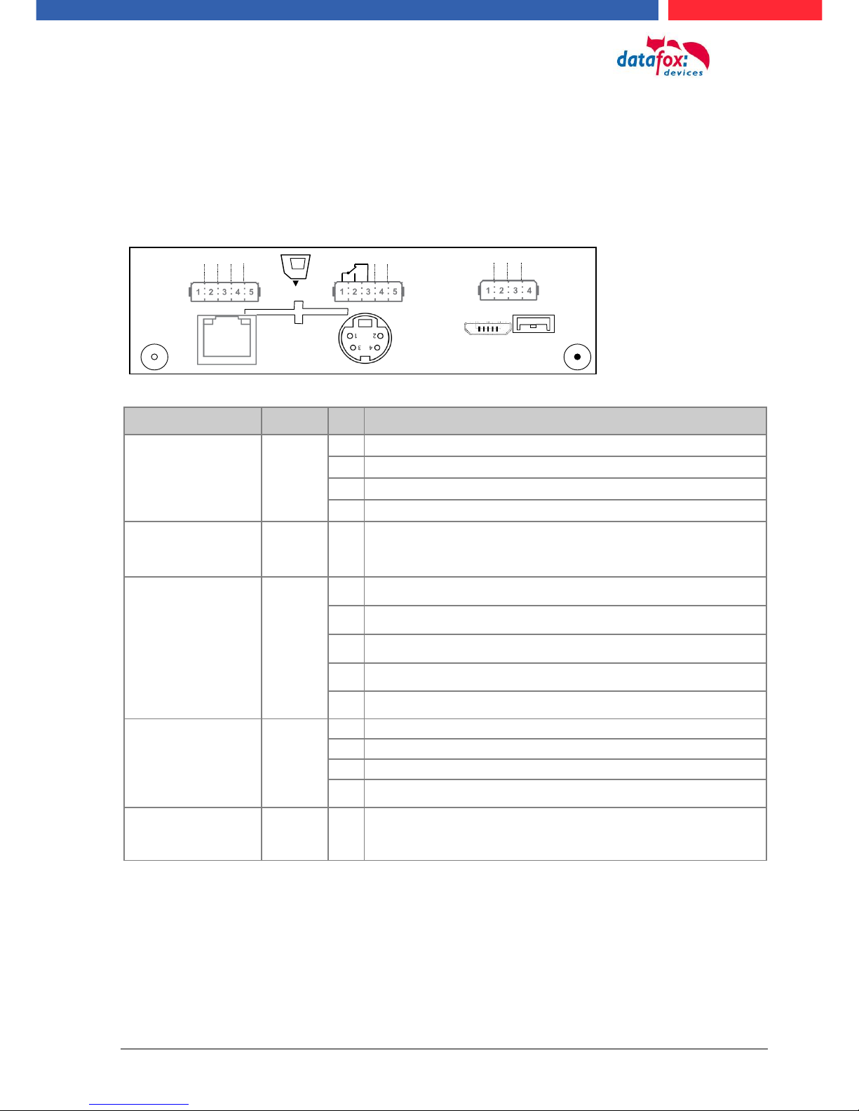
5.5.1. Connecting plugs
The EVO 3.5 Pure have intergatet 5 modulplaces. On this places can you order different modules.
You can choose the modules on the pricelist.
Steckerleiste des EVO 3.5 Pure V4
Bezeichnung
Modul
PIN
Beschreibung
Modulplatz 1
1
1
ground
2
A RS 485 for accesscontrol
3
B RS 485 for accesscontrol
4
12 V
Modulplatz 2
2
4-5
1-3
Standard:
1 digital input
1 digital output with nc and no contact
Modulplatz 3
3
1
1 digital input
2
2 digital input
3
3 digital input
4
4 digital input
5
ground
Modulplatz 7
RS 232
Mini-DIN M004
7
1
TXD
2
RXD
3
+ 5 V
4
Ground / GND
Modulplatz 8
8
TCP/IP - LAN
RJ 45
M1
SIM
12VDC
USB
GPRS
GPS
RS232
M7
LAN
M8
485-A
485-B
GND
12 V
M3
D IN1
DGND D IN2
D IN3
D IN4
M2
DGND D IN1
ZK
M1
SIM
12VDC
USB
GPRS GPS
RS232
M7
LAN
M8
M3
M2
DGND D IN1
Relais
ZK
485-A
485-B
HK
Variante mit RS485 Haupt-
kommunikation
Handbuch Datafox EVO 3.5 Pure Seite 23 Datum: 06.08.2018 Version: 04.03.07.XX
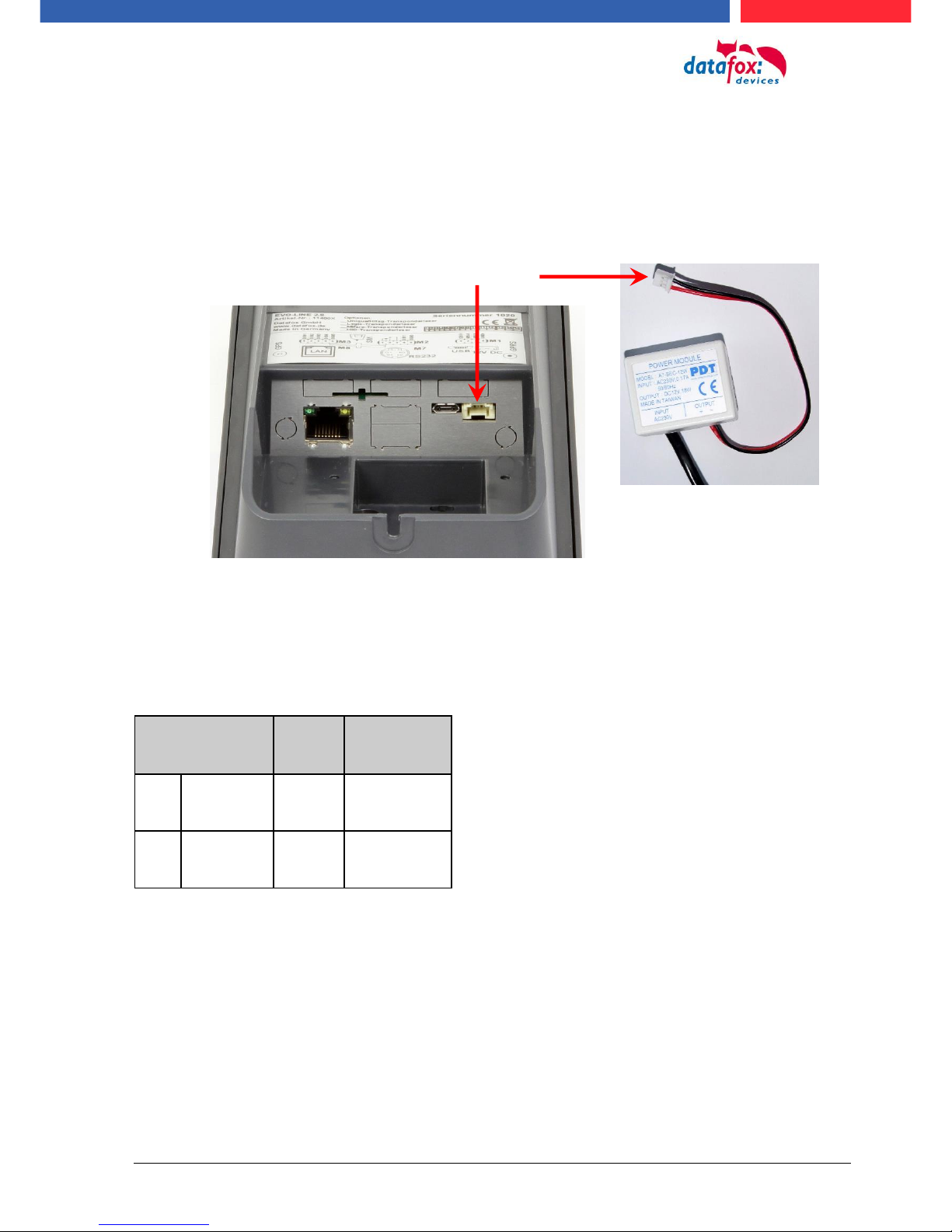
5.5.2. Powersupply of the EVO 2.8 / 3.5 Pure
The delivery power supply have 12V DC / 18 W.
The terminal itself can be supplied with a supply voltage of 24 V DC.
The power supply:
5.6. Power via POE for 2.8/3.5
An option for the power is a POE-modul (Art. Nr: 115117).
This POE-modul supporter 2 standards.
PoE-Standard
power
useable power
PoE
IEEE 802.3af
15,4 Watt
12,95 Watt
PoE+
IEEE 802.3at
25,4 Watt
21,90 Watt
If power is supplied via POE, an external access-reader can also be supplied via the access control
plug.
Reverse polarity protected connector
Handbuch Datafox EVO 3.5 Pure Seite 24 Datum: 06.08.2018 Version: 04.03.07.XX
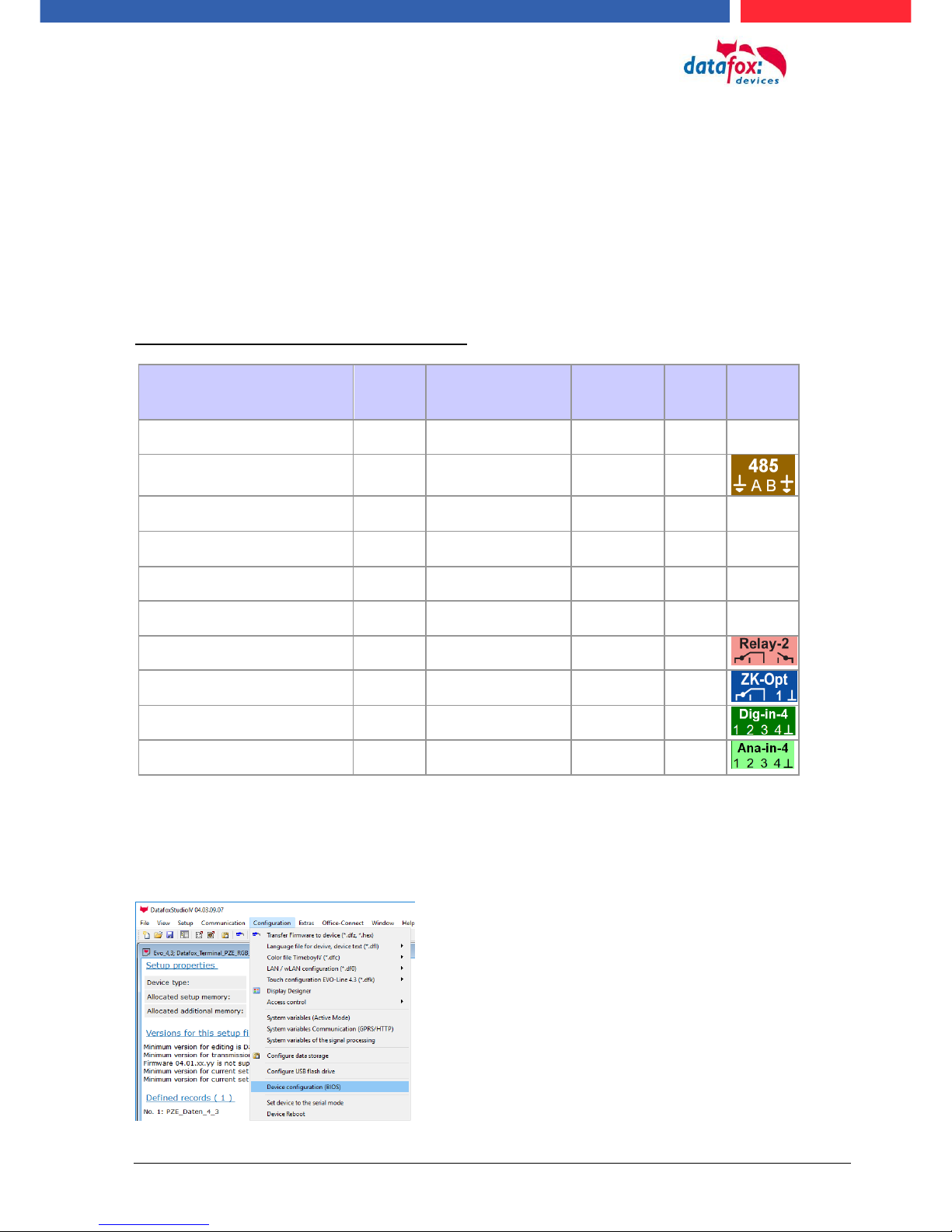
5.6.1. Modules for devices of hardware V4
5.6.1.1. Description of the various extension modules
The Datafox devices of the generation V4 are particularly distinguished by the variable configuration
of individual modules.
Depending on the device, a certain number of module locations are available.
These can be individually equipped with the individual available modules.
Depending on the size of the module, the individual modules occupy one or two module locations.
Thus, e.g. the GPRS module (mobile radio) requires 2 module slots and one relay module only
needs one module slot.
Overview of the different optional modules:
modul description
Required
module
slots
Description in the
BIOS-Menu and
Module mumber.:
Max. possible
number of
module
items
No. for
the
plug
overprint
&
Colour
RS 232 - mini DIN Barcode
1
032 Serial port mini DIN
1
RS 485 access
1
014 RS485 + 12V Supply
3
A310000
4-01
RS 485 for main communication
1
035 RS 485 Com Port
1
GPRS Mobile (Cell phone)
network
2
Mobile MC 55i
1
TCP/ IP
1
011 Ethernet Port
1
WLAN (WiFi)
1
001 WLAN Red Pine
1
2x digital Out
1
005 Relais Output
8
A310000
5-01
1x digital In +
1x digital Out
1
012 Digital In-/Output
8
4x digital In
1
006 Digital Input
8
A310000
5-02
4x anlog In
1
008 Analog Input
8
A310000
5-03
How manny modulplaces are usable you see device in the device manual in the chapter “Connec-
tion of device”.
5.7. Read the optional placement of the device
Click on:
„Configuration -> Device configuration (Bios)“
Then click on „Read“.

Handbuch Datafox EVO 3.5 Pure Seite 25 Datum: 06.08.2018 Version: 04.03.07.XX
Display in the Bios-Menu:
Here show all moduls they are fited in the device:
You see which module on which place is. You get extendet information how MAC adress, the number and order of the inputs and outputs.
E.g. Type lable of a IO-Box V4:
Example 1:
- Modulplace = M1
- Digital Input 1 to 4
- Module Number: = 006
Example 2:
- module slot = M4
- Analog Input 5 to 8
- Module Number: = 008 analog Input
You see here, in the IO-Box are
8 Modulplaces usable. This can be indi-
vidually fitted.
Exceptions:
- Modulplace 8, only here TCP is possible.
- RS 485 for access control - maximum 4
Modules can be fitted.

Handbuch Datafox EVO 3.5 Pure Seite 26 Datum: 06.08.2018 Version: 04.03.07.XX
5.7.1.1. Read out important module information from the device
Click on:
"Configuration -> Device Configuration BIOS"
Then click on "Status" thereafter
Click "Read".
1
2
3
4
5
6
7
8

Handbuch Datafox EVO 3.5 Pure Seite 27 Datum: 06.08.2018 Version: 04.03.07.XX
Here you will find a whole series of important information about the terminal.
Here are some explanations of the individual lines:
1) Name of the setup, this is also available when reading out.
2) The date when the setup was loaded into the device.
3) State of the digital inputs. All inputs which are physically present and defined in the setup are displayed
here with their status.
a. 00000000 = Digital inputs defined in the setup
b. 0 = Input on low (logical 0)
c. 1 = Input on hi (logical 1)
4) If digital inputs are defined in the setup as counter, the current count value is displayed here.
5) Status of the digital outputs: Output 1 is continuous here from left to right.
6) Analog inputs from left to right with respective currently applied voltage.
7) Number of stored records in the device and memory used.

Handbuch Datafox EVO 3.5 Pure Seite 28 Datum: 06.08.2018 Version: 04.03.07.XX
5.7.1.2. Connection of the individual modules
The connector / socket for the module always has the following assignment:
5.7.1.3. Analog inputs, 4 times analog IN
Socket on the device:
1 2 3 4 5
The plug can be inserted only in one direction and is therefore protected against reverse polarity.
plug
1 2 3 4 5
To loosen the cable, use a small screwdriver. Solid wires can be loosened by
twisting back and forth on the wire and
plug.
+ 0-10 V Signal 4
+ 0-10 V Signal 3
+ 0-10 V Signal 2
+ 0-10 V Signal 1
common ground;
GND / Ground

Handbuch Datafox EVO 3.5 Pure Seite 29 Datum: 06.08.2018 Version: 04.03.07.XX
5.7.1.4. 2 times digital out
Connection example:
(Connection of a signal light and a signal horn via a potential-free contact):
5.7.1.5. 1 time digital Out 1x digital IN
Connectiom example (Connection of a signal light and a door contact):
5.7.1.6. 4 times digital IN
Connectiom example (Connection of 4 contacts):
max. 30V AC /DC
2A / 60W
max. 30V AC/DC / 2A / 60W
e.g .: Door contact
max. 30V
0 - 1,5 V Input logical 0
3,5 V - 30 V Input logical 1
e.g.: 4x digital in
max. 30V
0 - 1,5 V Input logical 0
3,5 V - 30 V Input logical 1

Handbuch Datafox EVO 3.5 Pure Seite 30 Datum: 06.08.2018 Version: 04.03.07.XX
5.7.1.7. RS-485 bus for access control
The access control option provides the connection for external readers on the device.
The pin assignment looks as follows:
Note:
The 12 V are only present when the access control on the device is activated and all access lists have been played on the device.
Furthermore, the connection for a digital input and output is available.
The pin assignment looks as follows:
How the individual access components are connected or wired, can be found in the chapter "Access
control"
12V +
GND -
The power supply is sufficient for max. 1
external reader.
This voltage must not be combined with
other voltage sources.

Handbuch Datafox EVO 3.5 Pure Seite 31 Datum: 06.08.2018 Version: 04.03.07.XX
5.8. Communication of Hardware V4 Devices
!
Caution:
The type of communication depends on the device.
All possible communications are listet in the device.
Note:
Datafox-devices are able to communicate encrypted.
Read more in the manual for the „DatafoxStudioIV“.
The switching of the communication can be done
via :
1. the system menu bios on the device
2. with firmware version 04.02.04 and up with the function „Switch communication“.
3. from the Firmware version 04.02.04 upwards with the fieldfunktion „switch communication“.
Read more in the manual for the „DatafoxStudioIV“
Mögliche Kommunikationsarten sind:
1. USB (on PC)
2. USB Host, Save data on a USB-stick
3. TCP/IP over LAN
4. TCP/IP over the internet (with HTTP)
5. TCP/IP over WLAN
6. GPRS connection with mobil cell network.
5.8.1. Communication via USB
Every EVO-Line Device is equipped with an usb interface.
The Micro-USB-B Port can be connected directly to a PC.
!
Caution:
The Terminal works with a USB-B Interface. Das heißt, dass das Terminal im SlaveModus arbeitet und kann daher keine anderen USB-Geräte verwalten. This means that
the device works in slave mode only. So it is not possible for the device to control any
other devices via USB.

Handbuch Datafox EVO 3.5 Pure Seite 32 Datum: 06.08.2018 Version: 04.03.07.XX
5.8.2. Automatic dedected conectet USB to PC
If the terminal is connected to a pc it will recognize the connection and will switch the communication to USB.
It is not necessary to switch the main communication to usb manually.
It’s especially useful for boxed devices.
This will save much time in the parameterizing process.
Note:
If the device is connected to a pc no other connections (for example Wi-Fi) will happen
If the USB-cable is disconnected it will automatically switch to the configured main communication
DatafoxStudioIV will recognize the device and a notification will pop up.
The studio will generate
an entry for the device.
On the device the following icon is displayed:

Handbuch Datafox EVO 3.5 Pure Seite 33 Datum: 06.08.2018 Version: 04.03.07.XX
5.8.3. Installing USB driver for Hardware V4 Devices
Installation for Windows 7, 8, 8.1 and 10.
The USB-Driver is a small installer which will do the necessary configuration.
Just launch the .exe file.
Follow the instructions on the screen:
!
Caution:
Only use the driver wich are delivered with the device!
Note:
If you have DatafoxStudioIV installed the USB-driver will already be installed on your
pc.

Handbuch Datafox EVO 3.5 Pure Seite 34 Datum: 06.08.2018 Version: 04.03.07.XX
5.8.4. Comunication / record transfer via USB-Stick (Host)
The device dedected the stick automaticaly when the stick is plugged in.
The main communication must be set on “USB-Host“. You see the activated main communiction on
this symbol Symbol (Icon) .
The main communication can you set in the bios-menu.
USB - Stick adjust:
The USB stick is configured with the help of DatafoxStudioIV.
You find the configuration menu under the point „Configuration“->Configure USB flash drive.
More description you find in the manual “DatafoxStudioIV“.
Note:
We recoment to use a passoword for the communication with the USB-stick.
!
Caution:
The usb cable to the PC must not be connected if you want to use the stick on the device
!
Caution:
Lists of access control can be transferred individually, operation lists must always be
transmitted in complete form. All lists defined in the setup must also exist on the stick in
the "List" directory.
To be able to transfer data from the device to a
USB stick, the device must have the option
"USB host".
You can see this at the neckline.
The USB-Stick must be in FAT(32).

Handbuch Datafox EVO 3.5 Pure Seite 35 Datum: 06.08.2018 Version: 04.03.07.XX
5.8.4.1. Error message by using USB-Stick (Host)
Error code
Description
1
Read error
2
Write error
3
Error during the communication with the USB host
4
Error during the changing the directory
5
Error by the check of the stick
6
Error by the list directory
7
Error to create a data directory
8
Error handle
9
Error to open a file
10
Error not find the path
11
Error, the file is already open
12
Fehler to open a file
13
Error by closeing the file
14
Error by closeing the file, false handle
15
Error by checking the handle
16
Error by checking the handle, the file is not open
17
Error write protect
18
Error by the record stucture
19
Error duren the firmware update
20
No USB stick
21
Incorrect password
22
No list

Handbuch Datafox EVO 3.5 Pure Seite 36 Datum: 06.08.2018 Version: 04.03.07.XX
5.8.5. Communication via TCP / IP
The setting of the LAN / WLAN parameters is done via DatafoxStudioIV under the menu item "Configuration" -> "LAN / WLAN – Configuration (*.df0)“.
The LAN / WLAN configurations are saved in a file with the filename extension "*. df0".
Here you now have the possibility to edit the file, load it into the Datafox device (upload) or read it
from the device (download).
When reading the WLAN setting from the device, the currently specified file is overwritten.
In the General tab, first of all, you can set the main communication with which the device is
equipped.
- Device with LAN (The first configuration is for LAN connection)
- Device with WLAN
- Device with LAN and WLAN (The first configuration is for the LAN connection)
!
Coution:
For TimboyIV only this setting (only wLAN) can be used.

Handbuch Datafox EVO 3.5 Pure Seite 37 Datum: 06.08.2018 Version: 04.03.07.XX
5.8.5.1. Communication TCP / IP via network-cable
You can make the IP settings on the "LAN" tab.
For devices with display, the IP address can also be entered directly on the device.
Press ESC and ENTER simultaneously to enter the Bios menu of the device.
More information can be found in the chapter „bios menu“.
Please enter the desired IP address, subnet and if necessary a
gateway.

Handbuch Datafox EVO 3.5 Pure Seite 38 Datum: 06.08.2018 Version: 04.03.07.XX
5.8.5.2. Communication TCP / IP via wLAN / Wifi
This overview shows you which WLAN methods are supported.
Not supported is WPA (Predecessor of WPA2).
5 GHz connections are not supported and no mixed operation 2.4 GHz / 5 GHz.
Authentication via WPA2 Enterprise according to IEEE 802.1x is not supported.
!
Attention:
We cannot test every available Acsess-Point on the market.
Therefore, it is not possible for us to guarantee a connection to any AP.
When setting the encryption AES or WEP, only one type is used at a time.
The setting AES+WEP means for some access points that AES encryption is performed first and
then additionally encrypted with WEP.
In this case, only set AES.
Security:
None (0)
ohne
Security:
WEP(1)
WEP64
WEP128
Authentication
Open/None (0)
Shared/PSK (1)
NO Key
WLAN / Wifi – overview about
the encriptions and
„Infrastructure“
Encryption
Security:
WPA2/802.11i
AES / CCMP
„AES 128“
AES / CCMP +
WEP
Authentication
Shared/PSK
Encryption

Handbuch Datafox EVO 3.5 Pure Seite 39 Datum: 06.08.2018 Version: 04.03.07.XX
!
Attention:
A search for a new access point requires a lot of energy and drains the battery. Avoid a
continuous search for an access point when the device is operating at the limit by generously selecting the pause between scans for new access points (80-120s).
At most access points there is the possibility to set the "Beacon Interval". The higher this
is set, the less power the TimeboyIV needs. Recommendation: Beacon interval >300ms.
The entire file with all settings is transferred to the device. If the device has a display, the location
can be selected in the Bios menu -> Communication -> WLAN. Each location has its own configuration for the WLAN connection. The user therefore has no insight into the dial-in parameters at the
various locations.
Hint:
With automatic selection of the configuration / location, the first attempt is always made to
establish a connection with the default schema.
Select the configuration or location for
which you want to set the WLAN parameters.
If you check this box, the battery
life will be significantly increased
if the device is operated with a
rechargeable battery. Important
for TimeboyIV!
All the settings required for an access
point can be made here.
If a key is stored, this will be
displayed.
A scan (search) for access points is only carried out after a disconnection after this set time.
Please note the following Attention Box!
Enter the IP address for the device
here.
This must be the same for every location.

Handbuch Datafox EVO 3.5 Pure Seite 40 Datum: 06.08.2018 Version: 04.03.07.XX
5.8.5.3. Location selection in the Bios menu WLAN
5.8.5.4. Recommended setting
We recommend the following setting:
- WPA2
- AES
- Shared/PSK
Datafox uses the following access points internally for testing:
- Longshine LCS-WA5-45 IEEE802.11g
- WatchGuard XTM WEB UI
- Longshine IEEE802.11n
- TP-Link WR841N v6/v7 00000000
Setting StudioIV_WLAN-Device
Setting Access-Point
15.08.11 11:28:08
Datafox Support 74db
F1
F2
Datafox Gast 74db
Standort Geisa 86db
FA Muster 90db
Bios
Akt. Konfig.
?
?
All available WLAN networks are displayed in the Bios.
A configuration is stored for these networks
and can be selected.
These two networks were found by the
WLAN module, but there is no dial-in data available.

Handbuch Datafox EVO 3.5 Pure Seite 41 Datum: 06.08.2018 Version: 04.03.07.XX
5.8.5.5. Connection of the Terminals via TCP/IP DNS / DHCP
To connect a Datafox EVO-Device with the Hostname it is necessary to set something in the DNSServer. (In this example Windows-Server 2012)
Create a new Host (A)-value:
The entry should look like this:
Abbreviation
Descripion
Name
Name of the device
Contains the device designation and
the serialnumber
„deviceXX-serialnumber“
Example:
„Evo28-1652“ „EVO43-8552“
full qualified domain name
This is the host name to be entered
later.
IP-address
Here you must enter the IP of the device.
Create linked
PTR-record
You must create a linked PTR-record.
Just put this hook.

Handbuch Datafox EVO 3.5 Pure Seite 42 Datum: 06.08.2018 Version: 04.03.07.XX
Einstellung im Datafox Studio:
DHCP- entry for Datafox devices
If a device is set to DHCP, the IP address and the entry in the DHCP server can look like this.
The entry contains the following:
Host name
Before entering, this
checkbox must be set.

Handbuch Datafox EVO 3.5 Pure Seite 43 Datum: 06.08.2018 Version: 04.03.07.XX
device
serial number
domain
DHCP- entry
EVO 2.5
10245
.zentrale.de
Evo25-10245.zentrale.de
EVO 3.5
10246
.zentrale.de
Evo35-10246.zentrale.de
AE-Master
10247
.zentrale.de
AE-10247.zentrale.de
PZE-Master
10248
.zentrale.de
PZE-10248.zentrale.de
EVO 4.3
10249
.zentrale.de
Evo43-10249.zentrale.de

Handbuch Datafox EVO 3.5 Pure Seite 44 Datum: 06.08.2018 Version: 04.03.07.XX
5.8.6. Communication via RS485
5.8.6.1. Connecting the termina via RS485 to PC
Setting for communication in the DatafoxStudioIV for connection via RS 485:
RS 485 to PC
up to 1000m
RS 485 Anschluss
am Terminal
USB - RS485
Adapter am PC
Com-Port
See in the device manager on your PC
Baudrate 38400 and
Busnumber are to set in
the device bios menu

Handbuch Datafox EVO 3.5 Pure Seite 45 Datum: 06.08.2018 Version: 04.03.07.XX
5.8.6.2. Connecting the Terminal via RS485 with a Comserver Lantronix
Setting for communication in the DatafoxStudioIV for connection via RS 485:
120 Ohm
plugr 4 Pol.
BUS A
BUS B
Pin 1 - GND
plug 4 Pol.
BUS A
BUS B
Pin 1 - GND
plug
Pin 15 - BUS B
Pin 14 - BUS A
Pin 7 - GND
TCP/IP
RS485
IP and Port must set in
the comserver.
Baudrate 38400 and
Busnumber are to set in
the device bios menu

Handbuch Datafox EVO 3.5 Pure Seite 46 Datum: 06.08.2018 Version: 04.03.07.XX
Setting in the Comserver for connection via RS 485:
Port: for example 8000
IP: hier als Beispiel 192.168.123.224

Handbuch Datafox EVO 3.5 Pure Seite 47 Datum: 06.08.2018 Version: 04.03.07.XX
5.8.7. Communication via Cellular Network (GPRS)
The EVO 3.5 Purecan be equipped with a cellular network modem. It enables the communication
via cellular network. The antenna is located in the connection compartment of the device and can
optionally be replaced by an external antenna if reception is bad.
The SIM card is inserted via the connection compartment of the EVO 3.5 Pure.
Einsetzen der Sim-Karte beim Gerät
!
Caution:
For inserting the SIM card a tool in pen or screwdriver form is required. Take care that
the SIM card is not damaged.
For removing, the SIM card has to be pushed in a bit. After releasing it, the SIM card protrudes a bit
and can be removed.
Hinweis:
Wir empfehlen T-Mobile oder Vodafone als Provider für Mobilfunk einzusetzen! Unsere Erfahrung zeigt, dass bei anderen Anbietern mit häufigeren Einwahlen und damit auch verzögerter Datenübertragung und ggf. mit höheren Kosten gerechnet werden muss.
Informationen zu M2M:
http://www.t-mobile.de/business/machinetomachine/m2m-im-einsatz/0,23219,26762-_,00.html

Handbuch Datafox EVO 3.5 Pure Seite 48 Datum: 06.08.2018 Version: 04.03.07.XX
5.8.7.1. Communication state
The state of GPRS-/GSM-connection you can always see in the state bar on the display.
Pin
Bez.
0
Modem is off
1
Initialization of the software
2, 3
Start of the modem
4, 5
Initialization of the modem and SIM-card check
6
if PIN necessary, sending of the PIN
7
if PUK necessary, sending of the PUK
8
dilated initialization of the modem
10
Modem in standby mode
11
Call recognized
12
take calls
14
GSM connection activ
15, 16
GSM connection closed
20
GPRS Standby, Initialization of the GPRS connection after the first records
25
connection to Provider (Attach)
30
GPRS standby (waiting for next data/records)
31
Server (Open)
32
connect to server
33
send data to Server (HTTP)
34
Wait for quitting from server (HTTP)
35
recive data from server (TCP/IP)
36
send data to server (TCP/IP)
37
close connection
38
Braek between tries to connect the server, active mode
40
timeout after failed connection , to 15 minutes
411)
timeout after failed connection Provider, to 15 minutes.
421)
count of the connection attempt is end
43
on the Device is the encryption active, but not on the server
44
battery is down, to disable Modem.
45
impossible connect to the provider or bzw. Roaming impossible
50
close connection
55
Turn modem off

Handbuch Datafox EVO 3.5 Pure Seite 49 Datum: 06.08.2018 Version: 04.03.07.XX
5.8.8. Communication via SMS
5.8.8.1. Send a SMS
With the EVO 3.5 Pure, it's possible to send an SMS. Condition for this is, an integrated GPRSModem (communication via Cellular Network). The main communication must be set on GSM or
GPRS/GSM.
To send an SMS you must use the Field Function “send SMS” in the device Setup.
!
Caution:
Enter the phone number always with a country code.
Example.: +49161458
The device can be saved 128 SMS. Then there is additional as follows to clear the oldest SMS.
The call number if you want send an SMS must be saved in a GV.
The maximum length of the SMS is 160 characters.
The text can integrated device value:
%%: The percent signs self.
%V1 to %V8: value of global variable.
%T1: date and time 2012-08-07 12:13:14
%C1: Short device description. (PZE, AE, TIMEBOY, ...)
%C2: Serial number of the device. (max. 10 Stellen) %1 für GV 1, %2 für GV2 usw..
The function „send
SMS“ can you use in a
input field.

Handbuch Datafox EVO 3.5 Pure Seite 50 Datum: 06.08.2018 Version: 04.03.07.XX
5.8.8.2. Receive SMS
The follows functions are possible:
► View the SMS on the display. The sam action you find in the „DFCComSendMessage“ or
the answer via HTTP.
► to order an service connection (the same how in the HTTP- answer)
► start in the signal processing an input sequence
► Output an acoustic signal
Condition to receive a SMS is a KEY include in the device an in the text from the SMS.
The Key fort he device can set in the GPRS/HTTP .ini file.
Textmassage
The keyword must be included in the SMS-text is:
message=text1 text line2 line3 etc.
&delay=10&key=12345
The 10, is the time how long to display the message.
After the character gives a line break (carriage return).
If not a key in the device, you can use the serial number as a key (default setting). Save you an
empty Key, then receive the device every SMS. The last received SMS can you see in the
Bios-Menu under „general information Bios (Menu)“.

Handbuch Datafox EVO 3.5 Pure Seite 51 Datum: 06.08.2018 Version: 04.03.07.XX
Service-connection (active-mode)
The content of the SMS is similar to that of HTTP-Answer from the WEB-Server.
Actually supported are 3 keywords: service, host and port. The keyword must follow
an “=” character with corresponding value. The individual fields are separate with the character “&”.
With the KEY „service=1“, open the device a Service-connection. The connection Parameters
(Host, Port) are saved in the “active.ini” file from the device.
An option is, to give the device the Parameters for the connection via SMS (->host=, port=). Then
use the device this parameters from the SMS and not the saved from the “active.ini” (active mode).
“&service=2“
Coution ! this funktion first supportet with the hardware version V4 GPRS(Mobilfunk) and FW 04.03.06.XX.
When using parameter 2, the service connection is established immediately.
Beispiele:
a) service=X&key=12345
b) service=X&host=www.datafox.de&key=12345
c) service=X&host=123.123.123.123&key=12345
d) service=X&host=www.datafox.de&port=4711&key=12345
a) Connection to the server with the saved parameters in the „active mode“.
b) and c) Connection on Port 8000 to the server (www.datafox.de/123.123.123.123).
d) Connection to the server “www.datafox.de” and port “4711”.

Handbuch Datafox EVO 3.5 Pure Seite 52 Datum: 06.08.2018 Version: 04.03.07.XX
Start an input sequence in the device signal processing
The keyword, if you need in the SMS is:
ek=name&key=ja (the name of the input sequence).
The name of the input sequence must match completely, otherwise it will not run.
Receive the device an SMS with this text, then start the input sequence.
If save a SMS Key, the must included the SMS this Key (&key=ja).
With this are many different variants are possible.
Here some example:
Open a door via SMS.
Control a technical system and send a SMS in trouble:
Is the level of regulation from the system not correct then gives a report via SMS.
The Datafox MasterIV is here not the regulator. He gives only a report in trouble.
If necessary, a procedure also can be done.
!
Caution:
There is no 100% guarantee that a sent text message reaches the receiver. This is only
an example which is intended to represent the possibilities.
SMS from
device to you
oversize the
level
you can activate a
action
SMS to the
device
The Datafox-device
switch on a pump.
check
SMS
open the door

Handbuch Datafox EVO 3.5 Pure Seite 53 Datum: 06.08.2018 Version: 04.03.07.XX
ID
ZM
TM
RefLocation
RefAction
PINGeneral
Reader
1
ID
RefGroup
RefTime
RefTimenoPin
Location
3
ID
Weekdays
TimeStart
TimeEnd
Time
4
Day
RefGroup
RefTime
Holiday
5
ID
Group
PIN
Menace
ActiveStart
ActiveEnd
ActiveGeneral
Identification
2
RefReader
PortIn
RefAction
RefTime
Event
6
ID
RefReader
PortOut
Elapse
RefTime
Action
7
5.9. connection and wirering of the accesscontrol
5.9.1. Configuration of Access control adn stuckture
The basis of the access control II are tables. They store all information about the hardware configuration of the access control system, access right of the employees, periods of time (activation,
blocking times, holidays,...). The tables are connected as follows:
The tables are created as text files. For an easier administration you can add comments within the
files.
When adding comments, you have to notice that in a comment line no field values can be given and
that the comment line has to start with a semicolon.
The table Reader.txt might look like this:
ID
ZM
TM
RefLocation
RefAction
PinGeneral
1 1 320 0 1 0 2 1 000 1 2
0
3 1 010 2 3
0

Handbuch Datafox EVO 3.5 Pure Seite 54 Datum: 06.08.2018 Version: 04.03.07.XX
Holiday ControlIt is now possible for ZK-II to consider holidays at switching the relay. In order to
achieve compatibility with older versions, the function Consider Holidays for the Time Control of Relays has to be activated at the setup page Access Control 2. In the column Group, you specify the
Action ID of the switched relay output instead of a Group ID. Thus, it is not necessary to alter the
table structure of the holiday list. The column RefTime provides the time model applicable that day.
A minus sign must be inserted in front of the Action ID in order that the MasterIV terminal can differentiate between Action ID and Group ID. As a result, these Action IDs must be three-digit numbers.
Example:
Action
ID
RefReader
PortOut
Elapse
RefTime
1
10 1 25 0 2
11 1 25
0
3
12 1 0
0
Holiday
Day
RefGroup
„Action-ID“
RefTime
2012-05-01
1 3 2012-05-01
2 4 2012-05-01
-3
5
In the action list above, the door module with the ID 12 was assigned the time model 2 which
switches port 1 of the module. If separate holiday control has been activated in the setup, time
model 2 is not applied to the relay output at May 1, 2012, but time model 5.
Extended Parameterization ZK-II
The value range of the parameter 'ActiveGeneral' has been extended by the value 8. Additionally to
the general permission (value 9), a PIN request is executed - if defined so for the user and activated
for the reader. Furthermore, at both configurations of the ID cards with the ActiveGeneral value 8
and 9, the validity period of the ID card is checked.
For ZK-II the operation modes online, offline or online/offline after time-out are available. In online
mode, configuration lists stored in the device are not considered. A data record is read from the
server, analyzed and an action triggered. In offline mode, the configuration lists of the terminal are
used to grant or deny access to a person. Online / offline after time-out is a combination. If the server is unavailable, the terminal can decide on basis of its lists whether to grant access to a person or
not.

Handbuch Datafox EVO 3.5 Pure Seite 55 Datum: 06.08.2018 Version: 04.03.07.XX
Timing of the Digital Outputs for the MasterIV Device Series:
It is possible to time the digital outputs of the MasterIV device series via tables. Thus, for example
turning down the heating system at night, a buzzer control and much more can be realized.
The following tables must be configured:
► Action
► Reader
► Time
Description:
Each action that is to be activated must be entered in the table Action. The table Action refers to the
tables Reader and Time. In the table Reader the module is provided on which the relay or the Open
Collector is to be switched. The reference to the table Time indicates when the switch is to be done.
If start and stop time are entered, the relay is switched on when exceeding the start time and
switched off when exceeding the stop time. The entry of the duration Elapse in the table Action is
ignored. If the relay is only to be activated for a few seconds, e.g. for a buzzer control, the stop time
has to be set on "‘00 : 00"’. If the start time is exceeded, the respective output will be switched for X
seconds (RefTime in Action table). The entry Elapse in the table Action now indicates the on-time.
Example:
► A buzzer is to be activated for 3 seconds from Monday to Friday at 10.00 am and 4 pm
(16.00). The buzzer is controlled by the internal relay of the PZE-MasterIV.
► The heating system is to be set to the "‘day mode"’ at 07.00 am and to the "night mode" at 7
pm (19.00) on all weekdays. The corresponding relay is at the door module with the bus
number 2.
Reader.txt
ID
ZM
TM
RefLocation
RefAction
PinGeneral
1 1 320
0 0 0 2 1
020
0 0 0
Time.txt
ID
Weekdays
TimeEnd
TimeEnd
3
12345
10:00
00:00
4
12345
16:00
00:00
5
1234567
07:00
19:00
Action.txt
ID
RefReader
PortOut
Elapse
RefTime
6 1 1
15 3 7 1 1
15 4 8 2 1 0 5
5.9.1.1. Description of Tables for Access Control 2
Name
Data type
Length
Description
ID
Number
(int)
4
Unique Key (value>0) of the Reader table.
ZM
Number
(int)
4
In our example, it has number 1. If there are several PZE-MasterIVs in an access system, they can be depicted in one table connection and it is not necessary to have a separate string for each PZE-MasterIV.

Handbuch Datafox EVO 3.5 Pure Seite 56 Datum: 06.08.2018 Version: 04.03.07.XX
TM
Number
(int)
3
Contains two information in one number. Both figures on the left (010) indicate
the bus number of the door module, the figure on the right (010) contains information about the type of connection. A 0 means a connection via RS485, a 1
stands for a connection via RS232 as stub.
RefLocation
Number
(int)
4
Indicates which room is supervised by the reader.
RefAction
Number
(int)
4
Indicates which action is worked through after a successful check.
PinGeneral
Number
(int)
8
Can contain a numerical sequence by which a person without a card gets access.
Table Reader (List of all devices installed in the system)
Name
Data type
Length
Description
ID
Text
(ASCII)
20
Contains the ID card no. which is read at the TMR33 device or terminal. An ID
card can occur several times (is assigned to several authority groups).
Group
Number
(int)
4
Assigns the ID card to an authority group.
Pin
Number
(int)
8
Activates a PIN request if not equal 0. Please note that a PIN must not start
with zero. 0815 would be invalid.
Menace
Number
(int)
4
Activates (if not equal 0) a "‘menace-PIN"’ that can be added to the PIN. If entered, the system sends a data record that can be analyzed by software developed for this purpose and sets off the alarm.
ActiveStart
Text
(Date)
10
The tag entered here indicates the start date of the validity of the ID card.
(for example 2007-07-12 = yyyy-mm-dd)
ActiveEnd
Text
(Date)
10
The tag entered here indicates the end date of the validity of the ID card. (for
example 2007-07-12 = yyyy-mm-dd)
ActiveGeneral
Number
(int)
1
Activates or deactivates this card record.
0 = card blocked
1 = card active
2= virtual card (use only via DLL)
3 = access only by entering the PIN
8 = general authority (with PIN request)
9 = general authority (no PIN request)
Table Identification (list of all devices installed in the system - master and door modules)
Name
Data type
Length
Description
Day
Text
(Date)
10
Date of the blocking day. (form: YYYY-MM-DD)
RefGroup
Number
(int)
4
Indicates the authorization group to which the blocking day is applied. Zero defines a global validity for all groups.
RefTime
Text
(Time)
4
Indicates the assigned time model. (0 = not used) During this time access is
granted. Thus, also "‘half holidays"’ like New Year’s Eve can be realized.
Table Holiday (setting blocking days like holidays or company holidays)

Handbuch Datafox EVO 3.5 Pure Seite 57 Datum: 06.08.2018 Version: 04.03.07.XX
Identifier
Data type
Length
Description
ID
Number
(int)
4
ID of the room. All other tables refer to this data line via this number, if necessary.
RefGroup
Number
(int)
4
Reference to the identification table. Labels the access authorized group. All
cards of this group have access to this room.
RefTime
Number
(int)
4
The time model in which authorized persons get access. (0 = not used)
RefTimeNoPin
Number
(int)
4
The time model for which entering an additional PIN is not necessary (at peak
times etc.).
Table Location (defines which card groups get access to which room at which time)
Name
Data type
Length
Description
ID
Number
(int)
4
ID of the time model. All other tables refer to this data line via this number, if
necessary.
Weekdays
Number
(int)
7
Indicates the weekdays on which the following period of time should be applied
(form: 7 digits at most 1-7 e.g. 134567 = Monday, Wednesday till Sunday)
TimeStart
Text
(Time)
5
The start point for the period of time. (form: 24h HH:MM)
TimeEnd
Text
(Time)
5
The end point for the period of time.
Table Time (grouping of single time zones (weekday from to) as a time model number)
Name
Data type
Length
Description
RefReader
Number
(int)
4
Module (door module or master) where the digital input is.
PortIn
Number
(int)
1
Number of the digital input on the module.
RefAction
Number
(int)
4
Reference to the action that should be carried out (e.g. switch relay).
RefTime
Number
(int)
4
The time model which indicates when the digital input is checked. (0 = not
used).
Table Event (assigning an action to a signal at the digital input)
Name
Data type
Length
Description
ID
Number
(int)
4
Action number, it can occur several times due to several actions that have to be
worked through.
RefReader
Number
(int)
4
Module (door module or master) on which an output(relay) is switched.
PortOut
Number
(int)
1
Indicates the number of the output on the module.
Elapse
Number
(int)
3
The duration of the switching of the relay (0 = permanently). Unit 200 ms
RefTime
Number
(int)
4
The time model indicates when the output may be switched. (0 = not used)
Table Action (list of all workable actions in the access control system; an action group, i.e. all actions with the same action number, can switch several relays)

Handbuch Datafox EVO 3.5 Pure Seite 58 Datum: 06.08.2018 Version: 04.03.07.XX
If the device MasterIV is used for access control, door
supervision or remote monitoring, one device can supervise up to 8 doors and control 12 doors at most.
Flush-mounted: 81 x 81 x 11 mm (WxHxD)
Surface-mounted: 81 x 81 x 40 mm (WxHxD)
The VOXIO can be used with Legic or Mifare. It is available for in-wall or onwall mounting with or without keyboard. Each reader has a sabotage recognition, three lamps for visualizing the state and a buzzer for the acoustic signaling.
5.9.2. Access control II with PHG-Modules
The following hardware is available to set up an access control with PHG modules. The devices can
be combined in different ways according to their hardware requirements.
EVO 3.5 Pure
VOXIO
Relino
Relino B
IO-Box
From firmware version of the access reader 69806D of the PHG readers the autologin function for
Mifare is supported. Here for 5 of the max. 6 keys can be used in the setup.
!
Attention:
Technical data for the PHG access modules can be found on the Datafox DVD or in
our download area. Please note the power consumption of the modules and the voltage
drop at long cable lengths.
The responsibility for calculating the maximum cable lengths lies with the installer.
50 x 50 x 43 mm (WxHxD)
The RELINO(B) reader can be used with Legic or Mifare. It is available for
in-wall mounting. Each reader has three lamps for visualizing the state and a
buzzer for acoustic signaling.
51 x 48 x 22 mm (WxHxD)
The I/O box as equipment for the RFID wall reader or RELINO reader has
two digital inputs and two digital outputs. The I2C bus is used as interface.

Handbuch Datafox EVO 3.5 Pure Seite 59 Datum: 06.08.2018 Version: 04.03.07.XX
5.9.2.1. Connecting of PHG-reader
In order to connect the PHG modules, please note the PHG documentation on the Datafox CD:
<Datafox-Geräte- Datafox-Zutritt-Module PHG *.pdf>
In the PHG documents for the single modules, the pin assignment and configuration via the DIP
switches are described. In order to carry out an access control with theEVO 3.5 Pure the option
"‘access"’ has to be integrated (Datafox art. no. 105201). The following figure shows the possibilities
for connecting the PHG devices to a. The following figure shows the possibilities for connecting the
PHG devices to a EVO 3.5 Pure for access control.
The bus number of the module is set via the DIP switches 1 - 4. The DIP switch 5 always must be
set to "ON". The DIP switches 6 and 8 always must be set to "OFF". With the DIP switch 7 = "ON"
the RS485 bus is terminated at the last module, otherwise always "‘OFF"’.
If a door-opener is to be controlled additionally via a relay, the IO-box must be used.
With the IO-box two digital outputs as relays are available.

Handbuch Datafox EVO 3.5 Pure Seite 60 Datum: 06.08.2018 Version: 04.03.07.XX
floating relay
contact
I²C
max. 5 m
RS485
max. 1000 m
Reader
I/O-Box
Reader
I/O-Box
I2C max. 5m
ISTY 2x2x0,8
/
~
Connection example one door and I/O Box:
:
Power supply 12 V DC for reader
- + 3A

Handbuch Datafox EVO 3.5 Pure Seite 61 Datum: 06.08.2018 Version: 04.03.07.XX
Connecting example with one door and without I/O-Box:
Wire plan:
Wire plan for Siedle access reader:
TCP/IP
RS485
Türöffner
Busadresse
max. 42 V; 2A
Power supply for door opener
+ -
+ - max. 42V; 2A
Power supply for door opener
Bus Nr. 1
Siedle-access reader
Power supply 12 V DC for reader
- + 3A

Handbuch Datafox EVO 3.5 Pure Seite 62 Datum: 06.08.2018 Version: 04.03.07.XX
RS485 bus diagram for access control with 3 PHG- modules:
TCP/IP und
AC 100-230 V
I²C
max. 5 m
potential-free
contact for door
RS485
Reader
I²C
max. 5 m
potential-free
contact for door
RS485
I²C
max. 5 m
potential-free
contact for door
RS485
Reader
Reader
more reader
DIP-switch
setting
last reader
max. 1000 m
Last reader
end resistor
switch 7 -> on

Handbuch Datafox EVO 3.5 Pure Seite 63 Datum: 06.08.2018 Version: 04.03.07.XX
Door opener
–
+ GND A B
further reader
supply
12V 3A/DC
I2C max. 5m
ISTY 2x2x0,8
/ ~
– / ~
I2C max. 5m
ISTY 2x2x0,8
/ ~
– / ~
I2C max. 5m
ISTY 2x2x0,8
/ ~
– / ~
Door opener
Door opener
Wire plan PHG-reader:
In any case, a protection circuit should be integrated when connecting the door-opener.
A fly back diode for DC and an RC element for AC.

Handbuch Datafox EVO 3.5 Pure Seite 64 Datum: 06.08.2018 Version: 04.03.07.XX
Connecting the IO-Box:
Anschluss (ST1,2,3)
Klemme Nr.
Beschreibung
ST1
1
Relais 1 normaly close
2
Relais 1 common
3
Relais 1 normaly open
4
free
5
free
6
digital in 1 Signal
7
digital in 1 ground
ST2
1
Relais 2 normaly close
2
Relais 2 common
3
Relais 2 normaly open
4
free
5
free
6
digital in 2 Signal
7
digital in 2 ground
ST3
1 und 2
ground
3
U+ 8…..30V
4
SCL
5
SDA
ST 1 Circuit diagram
3 = “S“ normaly open
2 = “G“ common
1 = “Ö“ normaly close

Handbuch Datafox EVO 3.5 Pure Seite 65 Datum: 06.08.2018 Version: 04.03.07.XX
5.9.2.2. Configuration
The access modules work with internal encryption. The key is stored in the DatafoxStudioIV but not
visible.
If no key is provided under "AES Key" (PHG only), the default key is used.
!
Caution:
The key must only be changed at a fully installed access control. If you changed the key
and forgot it, the modules must be sent in. Restoring the default key is subject to a
charge.
All door modules that are compiled in the reader table have to be available in the RS485 network in
order to guarantee that the code can be changed in all modules if a new setup with a different code
is loaded. If a door module from the list in the bus is missing, the key is not changed. The old setup
with the old key has to be reloaded; otherwise, after rebooting the device, it is not possible to communicate with the door modules until the right key is used again.

Handbuch Datafox EVO 3.5 Pure Seite 66 Datum: 06.08.2018 Version: 04.03.07.XX
If a defective reader is replaced by a new reader that has not been used yet, it is recognized by the
firmware automatically at the start and the encryption is set up. The reader can also be replaced
during operation, the firmware automatically integrates it.
Contrary to GIS readers, PHG readers always have 2 digital inputs and a sabotage contact. The
firmware regards input 1 and input 2 as normal inputs with the number 1 and 2 and the sabotage
contact as number 3. The sabotage contact is integrated in the reader. The PHG reader has no analog-switch-input for door monitoring.
Additionally, the PHG reader can be extended by an IO box. The IO box has two digital inputs and
two relay outputs. The IO box is accessed via the same address like the reader. The two digital inputs have port number 4 and 5, the digital outputs port number 1 and 2. In case of discontinuity or
sabotage, port no. 6 is used.
PHG modules and firmware:
All configurations like tables etc. are to be configured in the same way as for the access readers of
the TS series.
Only exception:
The IO box is not specified in the reader table. Thus, information regarding the modules which are
connected via the I2C bus, is omitted.
Corresponding reader table:
ID
ZM
TM
RefLocation
RefAction
PinGeneral
Description
1
320 1 0 1 0
Master device
2
010 1 1 1 0
Reader at RS485
(PHG)
3
011 1 1 1 0
IO-Box at I2C-Bus
4
020 1 2 2 0
Reader at RS485
(LTM)
5
021 1 2 2 0
IO-Box at I2C-Bus
If you want to use the PHG
modules, you have to set it in
the Additional Options.
After changing over to the access readers of the PHG series,
the firmware must be transferred again.
The device then selects the respective firmware from the
DFZ-file.

Handbuch Datafox EVO 3.5 Pure Seite 67 Datum: 06.08.2018 Version: 04.03.07.XX
If the device MasterIV is used for access control, door
supervision or remote monitoring, one device can supervise up to 8 doors and control 12 doors at most.
diensions: 81 x 81 x 19 mm (BxHxT)
The EVO acceess reader can be used with 125 kHz, Legic or Mifare.
It is available for in-wall or on-wall mounting with or without keyboard. Each reader has a sabotage recognition, three lamps for visualizing the state and a buzzer for the acoustic signaling.
Signals from the backlight:
white permanent = Reader found an ready
white flashing = reader not found and not connection to the master
Signals from the backlight:
green = access accept
Signals from the backlight:
red = access denied or the master configured the read-
er currently.
5.9.3. Access control wiht EVO-access modules
The following hardware is available to set up an access control with EVO-modules. The devices can
be combined in different ways according to their hardware requirements.
EVO 3.5 Pure
EVO-access-reader
IO-modul for EVO-Access reader
Display
Backlit transponder symbol
3-coloured white, green, red
Individualization
Integrated backlight
Individual printable front glass with backlight 56 x 37mm
Colour always like transponder symbol
power supply
10 - 30V DC, max. 120mA
Environment values
Ambient temperature, Protection
-20 ° C to +70 ° C, IP65
Transponder systems
125kHz
Mifare
Legic
Hitag 1+2+S
Mifare Classic
Legic prime
Unique EM4102
Mifare Desfire
Legic advant
Titan EM4450
Mifare Ultralight
DGND
D IN1
Relay

Handbuch Datafox EVO 3.5 Pure Seite 68 Datum: 06.08.2018 Version: 04.03.07.XX
Connectors of EVO-reader:
DIP-switch:
switch number
Off
On
1 – address Bit 0
+ 0
+ 1
2 – address Bit 1
+ 0
+ 2
3 – address Bit 2
+ 0
+ 4
4 – address Bit 3
+ 0
+ 8
5 – terminate resistor 120 ohm
not activ
activ
example
5-4-3-2-1
address 2, with terminate resistor
1-0-0-1-0
address 3, without terminate resistor
0-0-0-1-1
pin
Number.
description
1
+10V bis +30V DC ! neu
2
RS 485-Data „B“
3
RS 485-Data „A“
4
GND ground
DIP-switch
Connector for IOmodul
Relay + digital in

Handbuch Datafox EVO 3.5 Pure Seite 69 Datum: 06.08.2018 Version: 04.03.07.XX
5.9.3.1. Connecting of the EVO-access reader examples
Cable plan for one door, 1 Relay in the EVO 3.5 Pure:
Reader Tabelle, for this example:
ID
ZM / Bus-ID
TM (Busadresse)
RefLocation
RefAction
PinGeneral
Beschreibungstext
1 1 010 1 1
0
Reader on RS485 Modulplace 1 = Bus ID 1
4 1 320 0 1 0 access-Box V4 (Masterdevice)
Wire plan for one access reader EVO:
TCP / IP (LAN)
M1
SIM
12VDC
USB
GPRS
GPS
RS232
M7
LAN
M8
485-A
485-B
12V
GND
M3
M2
DGND D IN1
Relais
ZK
485-A
485-B
HK
Variante mit RS485 Haupt-
kommunikation
RS 485 ZK Bus-ID 1
Bus Nr. 1
Bus Nr. 1
Türöffner Relais 1 der ZK-Box
12V vom Master
+ - max. 30V; 2A
Power supply for door opener
Bus Nr. 1
EVO-access reader
Connector 4 pole
for Access Bus
connector 5 pole
for digital in and
out

Handbuch Datafox EVO 3.5 Pure Seite 70 Datum: 06.08.2018 Version: 04.03.07.XX
5.9.4. Access control II with EVO-ZK-Plus-reader
5.9.4.1. Display and operation
The reader has a capacitive touch.
All images displayed by the reader and marked as standard below can be exchanged.
Display:
The entire display area is backed
by a touch screen.
With the DatafoxStudioIV, images
can be stored here for a gallery
display and for the necessary inputs/outputs.
See -> Configuration-> Display Designer.
Reading range of the transponder
with backlight in RGB colours.
The control of the LED is controlled exclusively by the readers
firmware.
access denied = red access permitted = green Bios activated = blue -

Handbuch Datafox EVO 3.5 Pure Seite 71 Datum: 06.08.2018 Version: 04.03.07.XX
5.9.4.2. Display for state of acces control
Currently there are 2 displayed states for:
granted access: access denied:
5.9.4.3. Display the number keypad
If an additional PIN is requested for access, the keypad will be displayed automatically. For access
only by entering a PIN, it is sufficient to briefly touch the display to activate the PIN display.
5.9.4.4. Errormessage
Datafox standard image
Datafox standard image
Datafox standard image
Picture 1 of the gallery
error
communication
The reader is in constant communication with the master.
If communication is interrupted, this
is indicated by the text "Communication error" on the reader.
Antippen
Datafox standard image
PIN normal
Datafox standard image
PIN randomization

Handbuch Datafox EVO 3.5 Pure Seite 72 Datum: 06.08.2018 Version: 04.03.07.XX
The following information can be called up in the general configuration:
- Installed firmware, serial number
- Memory allocation for the image memory
- Transponder test for the transponder configured in the master setup.
5.9.4.5. Bios-menu
Connect the reader to the 12V power supply with the connecting cable.
As soon as it is started, connect the reader via USB to a PC or a small battery (power bank).
The Bios menu can only be accessed when the USB port is powered.
Tap both top left and bottom right at the same time.
5.9.4.6. General configuration
USB
Power bank USB
USB port on the back of the
reader

Handbuch Datafox EVO 3.5 Pure Seite 73 Datum: 06.08.2018 Version: 04.03.07.XX
The bus terminating resistor of 120 Ω is switched on or off in
the bus configuration under "Terminating resistor".
Note: If it is the last or only reader in the RS485 bus, the termi-
nating resistor must be switched on.
The bus address is defined in the bus configuration under
"Bus number" .
Note that only bus addresses between 1 and 16 are possible.
The input of the bus number is confirmed with the "Enter"
key (bottom right).
With the Escape button (bottom left) the process can be
aborted.
5.9.4.7. Display configuration
The following parameters can be set in the display configuration:
- the brightness of the device
- random number keys - arrangement of the pin and keyboard
- the basic activation of the pin - keyboard
5.9.4.8. Bus configuration
In the bus configuration, the initial parameters that are used
for the setup of the reader must be set, configured.
5.9.4.9. Setting the bus adress of the reader for RS485 bus
5.9.4.10. Activate the resistor for the end

Handbuch Datafox EVO 3.5 Pure Seite 74 Datum: 06.08.2018 Version: 04.03.07.XX
connector 4 poles
access control
Bus plug:
5.9.4.11. Connection of the EVO-Access reader plus
On the backsite is a multicore cable.
The connection as fallows:
Nr.
color
function
1
red
+12V Power Input (10 - 30V DC)
2
blue
ground Power Input
3
yellow
RS485 - B
4
green
RS485 - A
I/O-Erweiterung
Housing
Structure
Front panel made of aluminium and glass, capacitive touch,
rear housing shell plastic: ABS
Dimensions ( width x height x depth )
85 mm x 208 mm x 27 mm, ca. 20mm additional in flush mounting
Weight
Basic device 570g plus wall mount plate 170g
Display
LCD
TFT: 320 x 480 Pixel, active area 49,0 x 73,4 mm with LED-Backlight
Backlit transponder symbol
3-coloured white, green, red
Keys
Type, size
Keyboard on touch screen, touch area 73,4 x 49,0mm
Individualization
Individual graphics
User information configurable by customer specific graphics
Integrated backlight
Individual printable front glass with backlight 56 x 37mm
Colour always like transponder symbol
Power supply
10 - 30V DC, max. 500mA
Installation
Stainless steel mounting plate, reader is clipped into the plate and secured
Environment values
Ambient temperature, Protection
-20 ° C to +70 ° C, IP65
Communication
RS485-interface, phg_crypt, 16 bus addresses and termination resistor configurable with menu
Sabotage sensor
Sabotage detection with distance control to wall mount plate
Options
Door module
Extension module with relay (SPDT) and one digital input
This extension should not be used in unsecured area.
Transponder systems
125kHz
Mifare
Legic
Hitag 1+2+S
Mifare Classic
Legic prime
Unique EM4102
Mifare Desfire
Legic advant
Titan EM4450
Mifare Ultralight
Nr.
color
function
5
white
Relay common
6
brown
Relay normaly open
7
gray
Relay normaly close
8
violet
Digital in, plus pole
9
black
Digital in, ground
Supply 12 – 30 V
- +

Handbuch Datafox EVO 3.5 Pure Seite 75 Datum: 06.08.2018 Version: 04.03.07.XX
Cable plan for 1 Door, 1 Relayin the EVO 3.5 Pure:
Reader Table, for this example:
ID
ZM / Bus-ID
TM (Busadresse)
RefLocation
RefAction
PinGeneral
description
1 1 010 1 1 0 Reader RS485 Modulplace 1 = Bus ID 1
4 1 320 0 1 0 (Masterdevice)
Recoment wirering for one Bus RS485 with one EVO-Reader-Plus:
Alternate can you use the power from the master device on the RS485 Moduls. Condition is: maximum one reader in use.
RFID Reader
Type
L in m
current in mA
Strom bei Start in mA
gf. Ergänzungen
Legic
50
iA
iA
Mifare
100
iA
iA
Unique
100
iA
iA
TCP / IP (LAN)
M1
SIM
12VDC
USB
GPRS
GPS
RS232
M7
LAN
M8
485-A
485-B
12V
GND
M3
M2
DGND D IN1
Relais
ZK
485-A
485-B
HK
Variante mit RS485 Haupt-
kommunikation
10-30V DC
+ - max. 30V; 2A
Supply for door opener
Bus Nr. 1
EVO-ZK-Leser-Plus
connector 4 poles
for access
control
connector 5 poles
for access
control
RS 485 ZK Bus-ID 1
Bus Nr. 1
Door opener relay on the master device
Supply
12 – 30 V - +
Maximum
recomment length = L

Handbuch Datafox EVO 3.5 Pure Seite 76 Datum: 06.08.2018 Version: 04.03.07.XX
Cable plan for 3 doors, 3 Relays in the EVO 3.5 Pure:
Reader Table, for this example:
ID
ZM / Bus-ID
TM (Busadresse)
RefLocation
RefAction
PinGeneral
description
1 1 010 1 1 0 reader Bus Nr. 1
2 1 020 2 2 0 readerit Bus Nr. 2
3 1 030 3 3 0 reader Bus Nr. 3
4 1 320 0 1 0 (Master device)
TCP / IP (LAN)
M1
SIM
12VDC
USB
GPRS
GPS
RS232
M7
LAN
M8
485-A
485-B
12V
GND
M3
M2
DGND D IN1
Relais
ZK
485-A
485-B
HK
Variante mit RS485 Haupt-
kommunikation
RS 485 ZK
Bus Nr. 1
Door opener relay 1
Supply for door opener
max. 30V; 2A
max.2,5 m
branch box
max.2,5 m
branch box
supply
12 – 30V DC per reader 500mA
max.2,5 m
branch box
Door opener relay 2
Door opener relay 3
Bus Nr. 2
Bus Nr. 3

Handbuch Datafox EVO 3.5 Pure Seite 77 Datum: 06.08.2018 Version: 04.03.07.XX
Wire plan for 3 doors, 3 Relays in the EVO 3.5 Pure:
M1
SIM
12VDC
USB
GPRS
GPS
RS232
M7
LAN
M8
485-A
485-B
12V
GND
M3
M2
DGND D IN1
Relais
ZK
485-A
485-B
HK
Variante mit RS485 Haupt-
kommunikation
Bus Nr. 1
supply 12 – 30 V + -
+ - supply for door opener
Bus Nr. 2
Bus Nr. 3
max. 2,5m
more reader possible
max. 2,5m
max. 2,5m

Handbuch Datafox EVO 3.5 Pure Seite 78 Datum: 06.08.2018 Version: 04.03.07.XX
5.9.5. Access control with TS-Readers
The following hardware is available to set-up access control with TS TMR33 modules. The different
options can be combined with each other according to the hardware requirements of the single devices.
EVO 3.5 Pure
Opening module (TS TMR33-TM)
72 x 72 x 40 mm
Reader (TS TMR33-L)
80 x 80 x 25 mm
Reader and Opening Module (TS TMR33-LTM)
80 x 80 x 25 mm
Note:
The single modules are connected to a bus. DIP switch 5 sets whether the modules are to
communicate via RS232 or RS485.
The MasterIV device supports the opening of up to 8 doors.
The door module is offered as pure electronic component e.g. to build it in a
padres box, or in a housing for surface mounting with alarm control panel.
The reader can be ordered separately to connect it directly to a PC or another
access check. A connecting diagram and a description of the commands for
the activation are included.
The module set can be ordered separately to connect it directly to a PC or another access check. A connecting diagram and a description of the commands
for the activation are included.

Handbuch Datafox EVO 3.5 Pure Seite 79 Datum: 06.08.2018 Version: 04.03.07.XX
5.9.5.1. Installation Variants
A Door without a Separate Reader
The EVO 3.5 Pure is access scanner, access master and door-opener at the same time. This solution should only be used in protected areas so that the door opening relay cannot be manipulated.
.
RS232/485
TCP/IP
GSM/GPRS
WLAN
!
Caution:
The installation and connection of the TMR33 module may only be carried out by a qualified specialist. Avoid switching the connecting terminal (reverse polarity).
Relay to the door
Digital input for door
monitoring
+ -
max. 42V; 2A
power supply for door opener

Handbuch Datafox EVO 3.5 Pure Seite 80 Datum: 06.08.2018 Version: 04.03.07.XX
A Door with a Separate Reader
The EVO 3.5 Pure is installed in a protected area inside a building and the reader is installed outside. The terminal is access master and door-opener at the same time. The door opening relay is in
the PZEMasterIV and thus installed in the protected area. The access identification captured by the
reader is transferred to the EVO 3.5 Pure and analyzed by it. If access is permitted, the door is
opened via the relay in the .
Installation plan:
This version is used frequently and can be installed easily and economically as shown in the figure
above.
Wiring plan:
:
Reader table for this example
ID
ZM
TM
RefLocation
RefAction
PinGeneral
Description
1 1 320 0 1 0 Access master
2 1 010 1 1 0 Reader on RS485 (L)
RS232/485
TCP/IP usw.
RS485 connection max. 1000 m
Relay to the door
Dorr monitoring
Reader (L)
Art-Nr.:106020
Power: max 30 V 2A
door opener
Reader module (L)
Art-Nr.:106020

Handbuch Datafox EVO 3.5 Pure Seite 81 Datum: 06.08.2018 Version: 04.03.07.XX
Several External Doors via RS485 Bus
Here, a door module has to be used so that the door opening relay is within the protected area.
Installation plan:
Wire plan:
Reader (L)
Art-Nr.:106020
RS232 connection max. 15 m
Relay for door
Door control
RS232/485
TCP/IP usw.
RS485 connection
max. 1000 m
RS232 connection max. 15 m
Relay for door
Door control
12V + -
Reader (L)
Art-Nr.:106020
max. 30V 2A
door opener
max. 30V 2A
door opener
Reader (L)
Art-Nr.:106020
Door
control
Door
control

Handbuch Datafox EVO 3.5 Pure Seite 82 Datum: 06.08.2018 Version: 04.03.07.XX
Several Internal Doors via RS485 Bus
The combined reader + door-module is used here. The door opening relay is included in the combined module. Caution: This assembly must not be used at outdoor locations because then the relay
is not within a protected area.
Installation plan:
Wire plan:
Button, for door opening from inside
RS232 connection max. 15 m
Relay for door
Door monitoring
RS232/485
TCP/IP usw.
RS485 connection
max. 1000 m
Relay for door
Door monitoring
Door – contact
Door monitoring
12V + -
Reader and door modul (LTM)
Art-Nr.:106030
ext. max. 30V 2A
Door opener
Reader and door modul (LTM)
Art-Nr.:106030
Door – contact
Door monitoring
ext. max. 30V 2A
Door opener
Button, for door opening
from inside

Handbuch Datafox EVO 3.5 Pure Seite 83 Datum: 06.08.2018 Version: 04.03.07.XX
Interlocking Function with RS485 Bus
The combined reader + door-module and the reader-module is used here.
Installation plan:
Corresponding reader table:
ID
ZM
TM
RefLocation
RefAction
PinGeneral
Description
1
320 1 0 1 0
Master on bus RS485
2
010 1 1 1 0
Reader and relay on RS485 (LTM)
3
011 1 1 1 0
Reader on RS232 (L)
4
020 1 2 2 0
Reader and relay on RS485 (LTM)
5
021 1 2 2 0
Reader on RS232 (L)
6
030 1 3 3 0
Reader and relay on RS485 (LTM)
7
031 1 3 3 0
Reader on RS232 (L)
RS232/485
TCP/IP usw.
RS485 connection
max. 1000 m
Relay for door
Door monitoring
RS232 connection max. 15 m
RS232 connection max. 15 m
Relay for door
Door monitoring
RS 485
Max.1000 m
LTM
Art-Nr.: 106030
Bus adress: 3
Bus adress: 2
Bus adress: 1
RS232 connection max. 15 m
Relay for door
Door monitoring
RS232 Verbindung max. 15m
Relais zum Türöffner
Türüberwachung
RS232/485
TCP/IP usw.
RS485 Verbindung
max. 1000m
Relais zum Türöffner
Türüberwachung

Handbuch Datafox EVO 3.5 Pure Seite 84 Datum: 06.08.2018 Version: 04.03.07.XX
Tür
Kontakt
Tür
Kontakt
ext. max 30V 2A
Door opener
ext. max 30V 2A
Door opener
Combination module (LTM)
Art-Nr.: 106030
Wire plan:
Note:
Connection for current supply via power supply unit or bell transformer. Please note the
hints for the calculation of the cable cross-section and the cable length. Install the dooropener in the protected area when using it for exterior doors.
At closed door contact ca. 15 mA are used up at 12 V = 0.18 Watt. This means a consumption of ca. 1.6 kWh per year.
12V + -
Reader module (L)
Art-Nr.:106020
ext. max 30V 2A
Door opener
Reader module (L)
Art-Nr.:106020
Tür
Kontakt
Reader module (L)
Art-Nr.:106020
Combination module (LTM)
Art-Nr.: 106030
Combination module (LTM)
Art-Nr.: 106030
Connector on the
MasterIV device

Handbuch Datafox EVO 3.5 Pure Seite 85 Datum: 06.08.2018 Version: 04.03.07.XX
5.9.5.2. Connecting the TS-series access reader
The following figure shows the possibilities for connecting the TMR33 devices to a PZE-MasterIV for
access control. The TMR33 devices have to be set depending on the interface used (RS232 or
RS485).
RS 485 RS 232
Settings of dip switch 6 Settings of dip switch 6
The DIP switches 1 - 5 are for bus configuration. Via the switches, the bus number of the device is
set. DIP switch 1 in position "ON" and switches 2 - 5 in position "‘OFF"’ stand for bus number "1".
DIP switches 1 and 2 in position "ON" and switches 3 - 5 in position "OFF" stand for bus no. "3".
Combination module
Reader + Relay TMR33
(LTM)
Door module TMR33
Relay (TM)
Combination module
Reader + Relay TMR33
(LTM)
Door module TMR33
Relay (TM)
Access MasterIV
ZK-; PZE-; AE-IV
Reader TMR33
(L)
Reader TMR33
(L)
More modules are possible.
PZE-MasterIV to 8 Modules
ZK-MasterIV to 16 Modules
Dip switch 8 is for terminate the RS485 bus line:

Handbuch Datafox EVO 3.5 Pure Seite 86 Datum: 06.08.2018 Version: 04.03.07.XX
Wiring plan:
More modules are possible.
Connector on the
MasterIV device
Reader module (L)
Art-Nr.:106020
Reader module (L)
Art-Nr.:106020
12V + -
ext. max 30V 2A
Door opener
Tür
Kontakt
Combination module (LTM)
Art-Nr.: 106030
ext. max 30V 2A
Door opener
Tür
Kontakt
ext. max 30V 2A
Door opener
Tür
Kontakt
ext. max 30V 2A
Door opener
Tür
Kontakt
Combination module (LTM)
Art-Nr.: 106030

Handbuch Datafox EVO 3.5 Pure Seite 87 Datum: 06.08.2018 Version: 04.03.07.XX
Setting the DIP Switches TS-TMR33
The addressing of the bus devices is effected by means of the DIP switches 1-5 (range 0-31). The
DIP-switch 6 serves for switching from RS232 to RS485 communication (for door modules no exter-
nal reader can be connected at RS232 communication). The DIP switch 7 is not used and must always be set to OFF. DIP switch 8 turns the termination of RS485 on/off; the switch must always be
turned on at the last module of the RS485 bus.
DIP switch
Meaning
1
Bus number (Bit 0)
2
Bus number (Bit 1)
3
Bus number (Bit 2)
4
Bus number (Bit 3)
5
Bus number (Bit 4)
6
DIP switch communication RS232 or RS485 (0=RS485, 1=RS232)
7
always OFF
8
Termination for RS485 bus (0= termination off, 1= termination on) 120Ω
Example bus address register:
Address
Bit 0
Bit 1
Bit 2
Bit 3
Bit 4
DIP switch
0 0 0 0 0
0
1 1 0 0 0
0
2 0 1 0 0 0 3 1 1 0 0
0
4 0 0 1 0
0
5 1 0 1 0 0 6 0 1 1 0 0 7 1 1 1 0
0
8 0 0 0 1
0
9 1 0 0 1
0
folder.

Handbuch Datafox EVO 3.5 Pure Seite 88 Datum: 06.08.2018 Version: 04.03.07.XX
5.9.6. Online funktions for the access control
The access control mechanism offers the functionality to control every configuration and action in
your software-solution.
So you can
This allows you to react to all requests from the access control in real time.
5.9.6.1. Online via http-protocoll
The communication with http is very quick and easy to set up. Therefor the webserver has an easy
job to react to the requests in a very short period of time.
Requirements:
Hardware:
- TCP/IP
- GPRS (1-2 seconds delay)
Software:
- Active Script with a logic for the access control and specially designed to suit the connected
hardware (ZK-Leser)
With the anser from the server you are able to perform specific actions with the access readers
The following examples will give you an insight in what is possible with the functions and actions.
All parameters correspond the online functions with the dll.
Activate the online function in the setup
under the basic settings tab.
There are 2 opetions:
- Offline Mode (the device always
waits for the answer from the
server)
- In the option Online/Offline the
terminal waits a definedtime before switching to the offline functionality. If this happens the terminal will use the access lists in
its memory.

Handbuch Datafox EVO 3.5 Pure Seite 89 Datum: 06.08.2018 Version: 04.03.07.XX
example 1:
The following data is going to be received
table=access&date_time=2013-07-05_07%3A48%3A11&
Master_ID=1&Modul_ID=010&Chip_Nr=2058&Status=34&checksum=2461
Master_ID=1 Master-ID
Modul_ID=010 bus adress of the reader / TM
Ausweis_Nr=2058 ID of the read Chip
Status=34 Online (34)
Fitting answer to grant access:
status=ok&checksum=2461&access=010&mask=8&type=1&duration=1
With firmware-version 04.03.04 and up also possible is:
status=ok&checksum=2461&master=1&module=010&mask=8&type=1&duration=1
access=010 bus adress, on which the action will take place (FW 04.03.03 and lower)
module=010 bus adress on which the action action will take place
master=1 rs485-bus on which the action action will take place
mask=8 relais Nr.1
type=1 turn-on
duration=1 for 1 second
Fitting anser to deny the access => Red-LED:
status=ok&checksum=2482&access=010&mask=5&type=1&duration=2
ab der Firmware 04.03.04 ebenfalls möglich ist:
status=ok&checksum=2461&master=1&module=010&mask=8&type=1&duration=1
access=010 bus adress, on which the action will take place (FW 04.03.03 and lower)
module=010 bus adress on which the action action will take place
master=1 rs485-bus on which the action action will take place
mask=5 red LED + buzzer
type=1 turn-on
duration=2 for 1 second
Several bus strings can be controlled with the new hardware V4. In order to be able to execute actions on the corresponding bus string, the bus string ID must be transferred with the response as
well.
For this, the new keywords "module" and "master" were implemented. These must be used together, replacing the keyword "access".
!
Attention:
The order “access->mask->typ->duration” or master->module->mask->typ>duration must be strictly adhered to.
status=ok&checksum=2482&access=010&mask=5&type=1&duration=2
status=ok&checksum=2482&master=1&module=010&mask=5&type=1&duration=2

Handbuch Datafox EVO 3.5 Pure Seite 90 Datum: 06.08.2018 Version: 04.03.07.XX
Overview of the possible parameters for the keywords:
keyword
value / Bit Nr.
description
access=
or
module=
function for
1x Bus
RS485
000
010
011
…
081 usw.
The value of the string must follow the format of the "TM" field of the
"Reader" list. He must therefore always include 3 digits.
master =
1-3
1
2
Id for the RS485 bus ZK, represents the ZK- rs485-bus.
RS485 Bus ID 1
RS485 Bus ID 2…
„master“ has to be set together with „module“ and so replaces the
function „access“
mask
1 / 0
this bit will trigger the buzzer.
2 / 1
this bit will trigger the green LED.
4 / 2
this bit will trigger the red LED.
8 / 3
this bit will trigger the first relay.
16 / 4
this bit will trigger the second relay.
32 / 5
this bit will trigger the third relay.
64 / 6
this bit will trigger the fourth relay.
128 / 7
this bit will trigger the fifth relay.
256 / 8
this bit will trigger the sixth relay.
….
unused. always set to 0
type
0
Off 1
On 2
change (600ms on, 600ms off)
3 3 times on for 500ms
duration
Sekunden / 0
Is a period of time and only at =1 active.
meaning: 0 = always on, 1 - 40 = seconds on.
Hint:
You can also perform multiple actions on the access control in one response. However,
the total length of the response must not exceed 254 characters.
!
Attention:
A automated switch between online and offline mode is not possible in http mode

Handbuch Datafox EVO 3.5 Pure Seite 91 Datum: 06.08.2018 Version: 04.03.07.XX
5.9.6.2. Online via DLL connection
The dll offers the function to directly access the external access reader. With the function “DFCEn-
trance2OnlineAction“you are able to trigger the buzzer, the LEDs and the relays.
In the case of an access booking, the access master generates a data record. This must be picked
up immediately and forwarded to the application on the server. The application then decides whether access is granted and returns a command to control the relay in the door module or lets the
buzzer sound and issues a visual message via the LEDs.
More dll functions are documented in the “Datafox SDK” on our website
http://www.datafox.de/softwarede.html?file=tl_files/Datafox_Devices/Downloads_Geraete_Zubehoer/MasterIVSoftware/Datafox_SDK_Windows.zip

Handbuch Datafox EVO 3.5 Pure Seite 92 Datum: 06.08.2018 Version: 04.03.07.XX
5.9.7. Function extention for access control II
5.9.7.1. General description
The access control has been extended to some functionality. To the table "Action 2" was introduced.
This table replaces the previously known “Action“. On the end of this chapter you find a description
for the table „Action2“. Due to a lot of additional references many scenarios are now possible.
The following example gives an overview:
5.9.7.2. Examples
Example - Garage:
Construct of Reader-, Location- , Action2- and Identification-table looks maybe at follows
Tabele Reader
ID
ZM
TM
RefLocation
RefAction
PinGeneral
Description text
1 1 320 0 0 0 Master device
2 1 010
100 0 0
Door-module on RS485 wire (TM1) only relays include
Need not a listing in the table „action“
3 1 011
100
1000
0
RFID-reader on RS232 wire (L1) only reader
All readings of RFID on this reader make all actions in the
table “action“, with the ID 1000.ID 1000.
4 1 020
200 0 0
Door-module on RS485 wire (TM2) only relays include
Need not a listing in the table „action“
5 1 021
200
2000
0
RFID-reader on RS232 wire (L2) only reader
All readings of RFID on this reader make all actions in the
table “action“, with the ID 2000.
6 1 030
300 0 0
Door-module on RS485 wire (TM3) only relays include
Need not a listing in the table „action“
7 1 031
300
3000
0
RFID-reader on RS232 wire (L3) only reader
All readings of RFID on this reader make all actions in the
table “action“, with the ID 3000.
Tabelle Time
ID
Weekdays
TimeStart
TimeEnd
Description text
1
1234567
00:01
23:59
24houers opening possible
2
1234567
07:00
16:00
Time for special action
The facility manager comes in the morning at 7.00 o´ clock and
uses the Entry 1.
- with his RFID-chip he opens the door 1 for 5 seconds.
- with the same action he gives the door 3 free, the opening is
now possible with a switch, until 4 o´ clock pm.
- entry 2 is now open until 4 o´ clock pm for the other person.
the closing is possible with:
- 1 – one RFID-chip registry on group 40
- 2 – double read of a normal RFID-chip
- 3 - Automatic at 4 o´ clock pm (define in the time table, see in
row 2 „RefTime“)
1
3
2
L1
TM1
L2
TM2
L3
TM3

Handbuch Datafox EVO 3.5 Pure Seite 93 Datum: 06.08.2018 Version: 04.03.07.XX
Tabelle Action2
ID
RefGroup
RefTime
RefReader
Relais
PortOut
Elapse
RefReader
LED
RefTime
Relais
Description
Read an RFID chip on reader 1
1000
10 0 2 1 5 3 0
Opening normal for 5s.
Group (10; 20; 30) have
always entrance
1000
20 0 2 1 5 3 0
1000
30 0 2 1 5 3 0
1000
30 2 4 1 32400
5
0
door 2 open for 9h
(max. 16:00)
1000
30 2 6 1 32400
7
0
door 2 open for 9h
(max. 16:00)
1000
40 0 2 1 -1 3 0
command door open, return
1000
40 0 4 1 -1 5 0
command door open, return
Read an RFID chip on reader 2
2000
10 0 4 1 5 5 0
Opening normal for 5s.
Group (10; 20; 30) have
always entrance
2000
20 0 4 1 5 5 0
2000
30 0 4 1 5 5 0
2000
30 2 4 1 32400
5
0
door 3 open for 9h
(max. 16:00)
2000
30 2 6 1 32400
7
0
door 3 open for 9h
(max. 16:00)
2000
40 0 4 1 -1 5 0
command door open, return
2000
40 0 6 1 -1 7 0
command door open, return
Read an RFID chip on reader 3
3000
0 0 6 1 5 0 0
This action is for all Groups
are listed in the table “Loca-
tion”.
Tabele Location
ID
refGroup
refTime
refTimeNoPin
Description
100
10 1 0
Group 10, 20, 30 and 40 have access on this reader.
100
20 1 0
100
30 1 0
100
40 1 0
200
10 1 0
Group 20 can not use this entrance 2.
200
30 1 0
200
40 1 0
300
10 1 0
The Master of Garage and the facility manager can open this
door.
300
30 1 0
Tabele Identification
ID
Group
Pin
Menace
ActiveStart
ActiveEnd
Active
Description
1111
10 0 0
2005-01-01
2015-12-31
1
Master of Garage
2222
20 0 0
2005-01-01
2015-12-31
1
Skilled workers
3333
30 0 0
2005-01-01
2015-12-31
1
Facility manager
4444
40 0 0
2005-01-01
2015-12-31
1
Facility manager second RFID-chip,
only for closing the door

Handbuch Datafox EVO 3.5 Pure Seite 94 Datum: 06.08.2018 Version: 04.03.07.XX
Example - elevator
The goal is to allow users only to exit at the allowed floor.
Then tenant usees the transponder to activate only the switch for his floor.
In the cabin of the elevator the RFID-reader is installed. The Datafox-Device is on the top of the
cabin.
Wirering plan for the EVO-Access reader:
Relay for floor 1
- RS485 Bus to the reader in the cabin
Relais for floor 2
Relay for floor 3
Relay for floor 4
Relay for floor 5
Relay for floor 6
… Relay for floor 12
+ - max. 30V; 2A
Bus Nr. 1
EVO-access-reader
Connector for
RS485 Bus
On the Modulplace 1
Relay 2 for floor
normaly close
Relay 1
With no/nc contact
Connector 5 poles
for 2 digital out
free potential
relay 2
relay 1
elevator con-
trol centre
 Loading...