

Page 1
Isolated Analog Signal Conditioning Products
DSCP
DSCP62 Conguration Guide
Thermocouple-to-DC Current/Voltage
Converter with Relay Output
Description
Each DSCP62 Thermocouple Converter provides a single channel of thermocouple
input which is amplified, linearized and converted to a high-level current or voltage
output. Thermocouple type, measurement range, filter, output type and range,
and fault indication may be configured by dip-switch. An auxiliary relay output
is provided to generate an alarm or act as a thermostat. Power can be applied
directly to the converter’s terminals or through a DIN rail mounted bus connector
accessory, eliminating the need to wire power to each individual converter.
Specifications Typical at T
Module DSCP62
Input (selectable)
Thermocouple Type
EN 60584-1 J, K, E, N, S, R, B, T
Input Impedance 10MΩ
Accuracy ±0.1% (max)
Cold Junction Error 1.5°C (max)
Thermal Drift <120ppm/°K
A/D Conversion 14-bit
Processing Floating point 32-bit
Response Time, 90% Span
(selectable) <25ms (without filter), <55ms (with filter)
CMRR
Isolation 1500Vrms (1 minute), 3-Way
Dip-Switch Configuration Sets input and output ranges, sensor type,
Status Indicators (LED) Internal fault, configuration error,
Output (selectable)
Current 0 to 20, 4 to 20, 20 to 0 or 20 to 4mA
Current Output Protection 25mA (max)
Fault Output 102.5% or 105% of full-scale value in
Voltage 0 to 5, 1 to 5, 0 to 10 or 10 to 0VDC
Auxiliary Relay Output Rated 60mA (max) at 24VAC
Power Supply 19.2 to 30VDC
Power Consumption <600mW (24mA at 24VDC)
Hot Swapping Yes
Environmental
Operating Temp. Range –20°C to +65°C
Storage Temp. Range –40°C to +85°C
Relative Humidity 0 to 90%, Noncondensing
IP Protection IP20
Emissions EN61000-6-4
Immunity EN61000-6-2
Mechanical Dimensions (w x h x d) 0.24" x 3.67" x 4.04"
Housing Terminal housing for mounting on
Connections
Weight 1.6 ounces (46g)
=+25°C and +24VDC power
A
Measurement range: Depends on
thermocouple type and dip-switch setting
>135dB, referred to power supply side
Load resistance: 500Ω (max)
Load resistance: 2kΩ (min)
(6.2mm x 93.1mm x 102.5mm)
Span: 100°C (min)
filter and faults
connection fault
case of over-range
35mm DIN 46277
Spring cage clamp
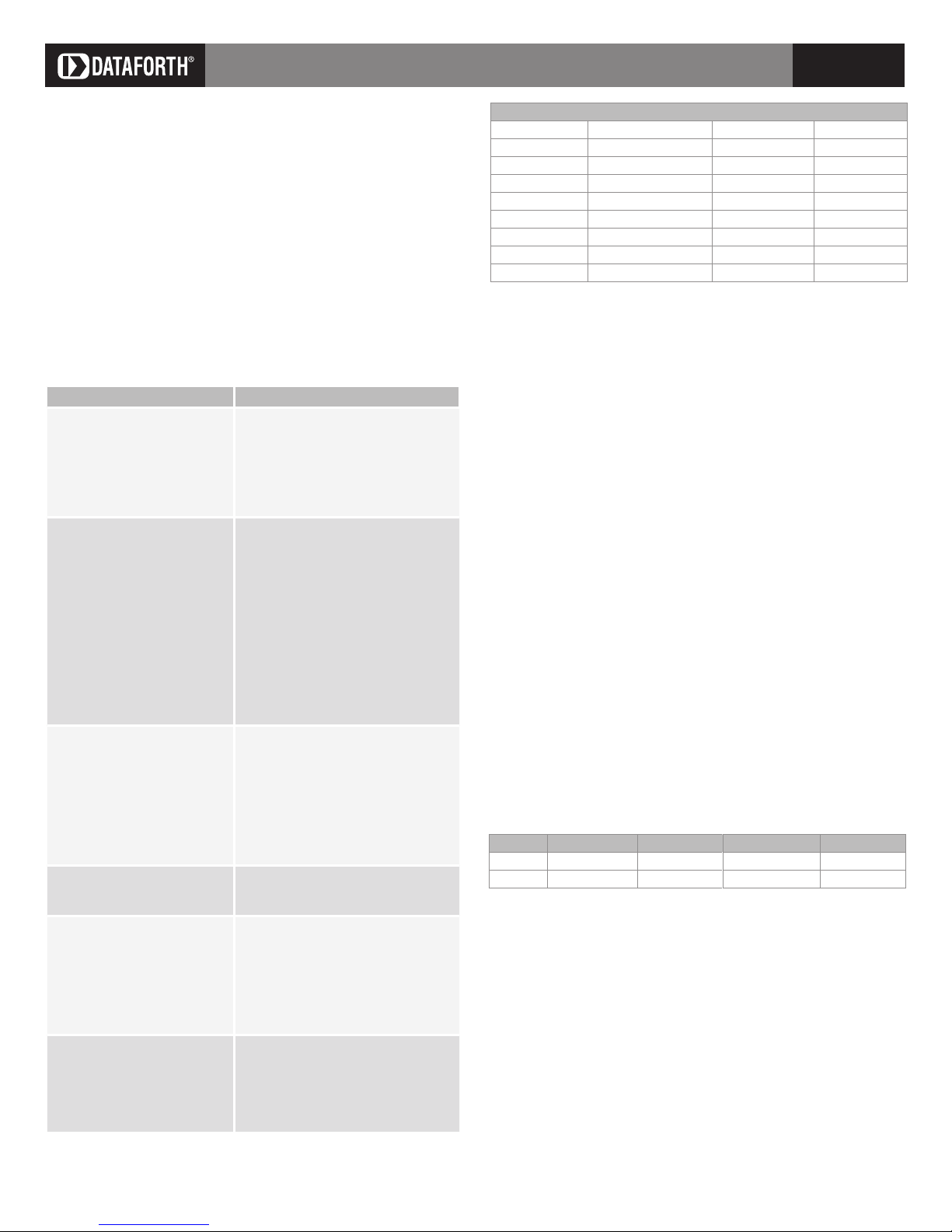
Range and precision of the input
Thermocouple
J –210 to 1200°C 0.025% + 0.29°C 0.12°C
K –200 to 1372°C 0.025% + 0.4°C 0.17°C
E –200 to 1000°C 0.025% + 0.2°C 0.92°C
N –200 to 1300°C 0.025% + 0.42°C 0.19°C
S –50 to 1768°C 0.025% + 1.34°C 0.66°C
R –50 to 1768°C 0.025% + 1.19°C 0.59°C
B 250 to 1820°C * 0.025% + 1.87°C 0.9°C
T –200 to 400°C 0.025% + 0.31°C 0.13°C
* Up to 250°C, the output is considered equivalent to 0°C.
Range Mean error Resolution
Auxiliary Output
The auxiliary output is designed to drive an indicator, a relay of greater
power, or the input of a supervisory control system. Through this output the
DSCP62 module can generate an alarm or be utilized like a thermostat. The
normal state of the output depends on the configuration for the fault of the
primary output.
Setting the threshold
The regulation of the threshold is performed through a button located under
the front cover of the module and accessible through the hole using a small
screwdriver.
• Press and release the button. The primary output will start to represent
the value of threshold and the red LED will flash slowly.
• If the button is not pressed again within 5 seconds, the system will
return to standard functioning.
• Each time the button is pressed there is an increase or decrease of the
primary output of approximately 0.2%; the direction of the variation
depends on the configuration of the output.
• If the button is not released but continues to be pressed, a continuous
3% increase starts after 2 seconds.
• When the maximum/minimum value of the chosen scale is reached, the
cycle starts again.
• During regulation of the threshold, the auxiliary output follows standard
functioning, opening and closing as previously set.
• After 5 seconds of no button pressing, the set value is memorized and
the module continues with standard functioning.
Dip-switch SW2.7 details
SW2.7 Regulation type Fault Standard state Set threshold
OFF Furnace * Upscale Closed (LED ON) Decrease
ON Refrigerator * Downscale Open (LED OFF) Increase
* In case of choice of direct output: 0(4) to 20mA, 0(1) to 5(10)V
Installation rules
This module is designed for assembly on a DIN 46277 rail. Assembly in a
vertical position is recommended to increase the module’s ventilation. Be
sure that no raceways or other objects that compromise aeration are positioned in the vicinity, and do not position the module above equipment that
generates heat. We recommend positioning the module in the lower part of
the control panel or container compartment. We also recommend rail-type
assembly using the Power Bus connector, which eliminates the need to connect the power supply to each module.
Dataforth Corporation
3331 E. Hemisphere Loop • Tucson, AZ 85706 USA • Toll Free: 800-444-7644 • Tel: 520-741-1404 • Fax: 520-741-0762 • Email: sales@dataforth.com • www.dataforth.com
SD1145 02/11 ©2011 Dataforth Corporation, All Rights Reserved ISO9001:2008 Registered QMS 1
Page 2
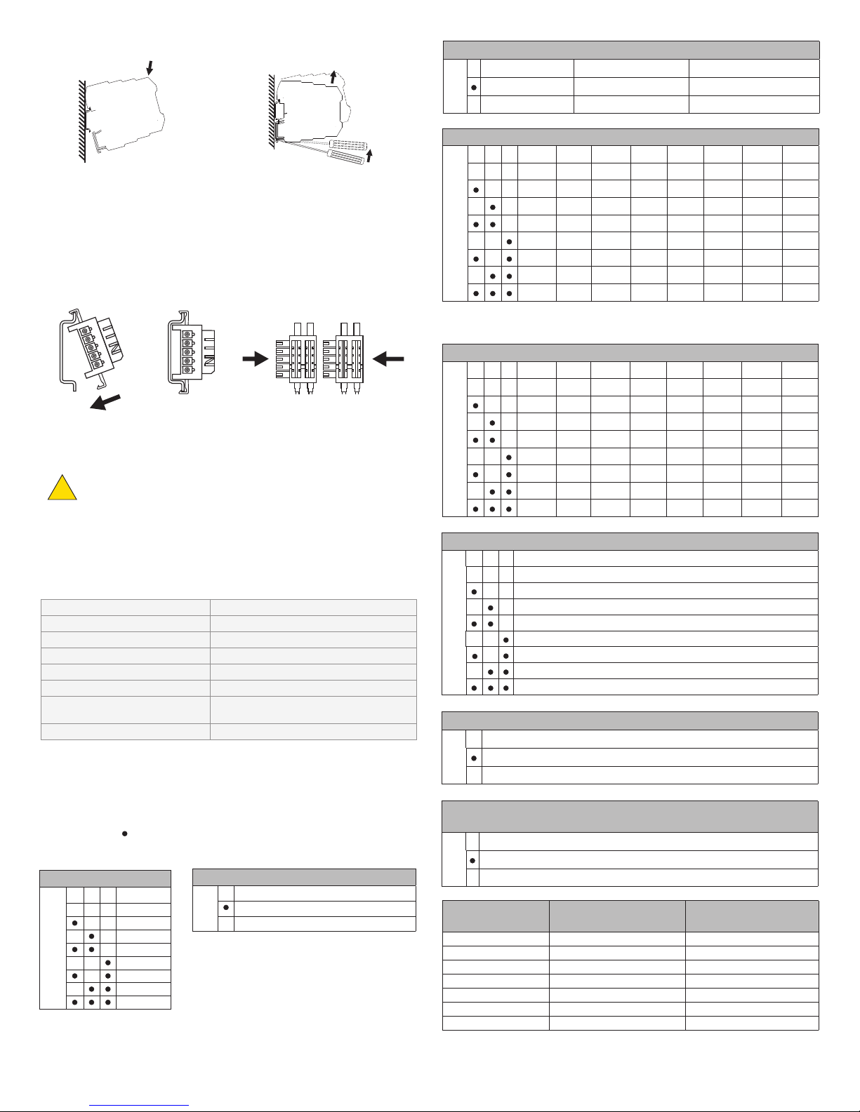
Inserting module in DIN rail Extracting module from DIN rail
1. Attach module in upper part of rail.
2. Press module downward.
1. Apply leverage using a screwdriver
(as shown in figure).
2. Rotate module upward.
Using the Power-Bus connector
Each expandable Power-Bus connector allows insertion of two modules.
Insert Power-Bus connectors into the DIN rail by attaching to upper side of
rail and rotating downward.
NOTE:
The Power-Bus must be inserted with protruding terminals on the left (as
shown in figure above); otherwise the modules are turned upside down.
Never connect power supply directly to the bus connector on
the DIN rail. Never tap power from the bus connector either
!
directly or by using module terminals.
Input filter
SW1 5 10-90% response, 50Hz 10-90% response, 60Hz
Enabled <55ms <55ms
Not enabled <25ms <25ms
Measurement range start
SW1 6 7 8 J type K type R type S type T type B type E type N type
Default * 0°C 0°C 0°C 0°C 0°C 0°C 0°C
0°C 100°C 100°C 100°C 50°C 400°C 100°C 100°C
100°C 200°C 200°C 200°C 100°C 500°C 200°C 200°C
200°C 400°C 300°C 300°C 200°C 600°C 300°C 300°C
300°C 600°C 400°C 400°C –50°C 800°C 400°C 500°C
500°C 800°C 600°C 600°C –150°C 1000°C 500°C 700°C
–100°C –100°C 800°C 800°C –100°C 1200°C –100°C –100°C
–200°C –200°C 1000°C 1000°C –200°C 1400°C –200°C –200°C
* If all the dip-switches are in the OFF position, the default configuration is valid; otherwise the value
of this parameter is 0°C, as for the other thermocouple types.
Measurement range end
SW2 1 2 3 J type K type R type S type T type B type E type N type
1200°C 1350°C 1750°C 1750°C 400°C 1800°C 1000°C 1300°C
1000°C 1200°C 1500°C 1500°C 350°C 1600°C 800°C 1200°C
800°C 1000°C 1300°C 1300°C 300°C 1500°C 600°C 1000°C
600°C 800°C 1100°C 1100°C 250°C 1300°C 500°C 800°C
500°C 700°C 900°C 900°C 200°C 1100°C 400°C 600°C
400°C 500°C 700°C 700°C 150°C 900°C 300°C 500°C
300°C 300°C 500°C 500°C 100°C 700°C 200°C 400°C
200°C 200°C 300°C 300°C 50°C 500°C 100°C 200°C
Factory dip-switch settings
The module leaves the factory with all dip-switches in the OFF position.
The default configuration is as follows:
Thermocouple type
50/60Hz line rejection 50Hz
Input filter Not enabled
Measurement range 0 to 1200°C
Output signal 4 to 20mA
Output signal in case of open input Toward the top of the output range
Input over-range Output signal is limited to +5% of max
Auxiliary output threshold 0% of the nominal scale
J
(or –5% of min) with input over-ranged
This configuration is valid only with all dip-switches in the OFF position. If
even one dip-switch is not in the OFF position, all parameters must be set
SW2 4 5 6
4 to 20mA
0 to 20mA
20 to 4mA
20 to 0mA
0 to 10V
1 to 5V
10 to 0V
0 to 5V
Output signal in case of open input
SW2 7
ON: Toward the bottom of the output range
OFF: Toward the top of the output range
Output signal
as indicated in the following tables.
NOTE:
The indication means the dip-switch is set in the ON position.
No indication means the dip-switch is set in the OFF position.
Thermocouple type
SW1 1 2 3
SW1 4
J
K
R
S
T
B
E
N
50/60Hz line rejection
60Hz
50Hz
SW2 8
ON: Output signal is limited to ±2.5% of full-scale setting with input over- / under-ranged
OFF: Output signal is limited to ±5% of full-scale setting with input over- / under-ranged
Nominal output value
20mA 20.5mA 21mA
4mA 3.5mA 3mA
0mA 0mA 0mA
10VDC 10.25VDC 10.5VDC
5VDC 5.125VDC 5.25VDC
1VDC 0.875VDC 0.75VDC
0VDC 0VDC 0VDC
Over-range / Under-range Options
(See table below for corresponding values)
Over- / Under-range limited to
±2.5% of full-scale setting
Over- / Under-range limited to
±5% of full-scale setting
Dataforth Corporation
3331 E. Hemisphere Loop • Tucson, AZ 85706 USA • Toll Free: 800-444-7644 • Tel: 520-741-1404 • Fax: 520-741-0762 • Email: sales@dataforth.com • www.dataforth.com
SD1145 02/11 ©2011 Dataforth Corporation, All Rights Reserved ISO9001:2008 Registered QMS 2
Page 3

LED indications on front of module
1
2
3
4
5
6
7
8
Output
Input
Power
supply
AUX
AUX
Red LED Meaning Output fault
Internal fault: power supply not
Fast flashing
Slow flashing
Steady light
* In this modality the output signal represents the value of the threshold.
sufficient, out of range offset or
reference. Error on reading or
Yes
writing in flash (at the start or on
threshold setting).
Dip-switch setting error Yes
Set threshold in progress No *
Disconnected thermocouple, out
of range input or temperature
Yes
compensation
Output limiting in progress No
Input
The module accepts input from the following types of thermocouples:
J, K, R, S, T, B, E, N.
The use of shielded cables is recommended for the electronic connections
6
7
8
Power
supply
5
Output
Input
1
2
+
3
TC
4
Yellow LED Meaning
ON The auxiliary output is closed
OFF The auxiliary output is open
Electrical connections
The module is designed for spring cage clamp
electrical connections.
1. Strip cables by 0.8mm.
2. Insert screwdriver in the square hole and press
until the cable lock spring opens.
0.2 to 2.5mm
2
8mm
3. Insert cable in the round hole.
4. Remove screwdriver and ensure cable is tightly
fastened in the terminal.
6
7
8
Power
supply
Red LED
5
Power supply
Set threshold
+
-
Yellow LED
1
2
3
4
Output: Voltage / Current connections
The use of shielded cables is recommended for the electronic connections.
+
V / I
5
6
7
8
Power
supply
Output
Input
1
2
3
4
Auxiliary output
The auxiliary output is designed to drive an indicator, a relay of greater
power, or the input of a supervisory control system.
AUX
AUX
2
3
4
6
7
8
Power
supply
5
Output
1
Input
There are three ways to power the DSCP6x series of signal converters.
1. Connect the 24VDC power supply directly to terminals 7 (+) and 8 (-)
of each module.
2. Connect power to one signal converter and use the expandable PowerBus connector to distribute power to a maximum of 16 adjacent modules.
The bus can be supplied from any of the modules, but the total current
consumption of the bus must be less than 400mA. Higher consumption
values can damage the module. An appropriately sized fuse must be
connected in series with the power supply.
3. Use the DSCP70 Power Supply Connection Module and the expandable
Power-Bus connector to distribute power to a maximum of 75 modules.
The DSCP70 is designed to protect the modules connected via bus against
overvoltage loads. The bus connector can be provided with power using the
DSCP70 module if the total consumption of the bus is less than 1.5A. Higher
consumption values can damage both the module and the bus. An appropriately sized fuse must be connected in series with the power supply.
Dataforth Corporation
3331 E. Hemisphere Loop • Tucson, AZ 85706 USA • Toll Free: 800-444-7644 • Tel: 520-741-1404 • Fax: 520-741-0762 • Email: sales@dataforth.com • www.dataforth.com
SD1145 02/11 ©2011 Dataforth Corporation, All Rights Reserved ISO9001:2008 Registered QMS 3
 Loading...