

Data Flow Systems Hyper SCADA HSS001 Quick Start Manual
HSS Serial Number HSM Serial Number
NIM Serial Number NSM Serial Number
PSM Serial Number
HSM IP Address: _________________________________________________
NIM IP Address: _________________________________________________
Backup Computer IP Address: _____________________________________

NOTICE
Data Flow Systems, Inc. assumes no responsibility for any errors that may
appear in this document, nor does it make any commitment to update the
information contained herein. However, questions regarding the information
contained in this document are welcomed.
Data Flow Systems also reserves the right to make changes to the specifications
of the Hyper SCADA Server, Hyper Server Module, Network Interface
Module, Fiber Interface Module, Network Fiber Module, Network Switch
Module, and the HT3 SCADA software and to the information contained in
this document at any time without notice.
© Data Flow Systems, Inc.
605 N. John Rodes Blvd., Melbourne, FL 32934
Phone 321-259-5009
Fax 321-259-4006
www.dataflowsys.com
DFS-00387-011-01
This document last updated June 4, 2010

HSS001 Quick Start Guide
This document describes the basic procedures for cabling and configuring the
Hyper SCADA Server (HSS001). For detailed cabling and installation
information, see the Hyper SCADA Server Installation and Operation Manual,
available for download from DFS’ web site (www.dataflowsys.com). For
detailed information on configuring the HT3 SCADA software, see the HT3
User Guide (available from within the HT3 software and also available on the
DFS website).
Parts List
Hyper SCADA Server (HSS002-1 or HSS002-2), which includes the following
components:
One Hyper Server Module (HSM)
One 100 W Power Supply Module (PSM)
One on the following: Network Interface Module (NIM); Fiber Interface
Module (FIM); or Network Fiber Module (NFM)
One Network Switch Module (NSM)
One 3.0 AH battery
Two telephone line connectors
Two serial ports
One RCA mono jack
AC power cord (10 feet) (optional power cord plug is available)
4 (four) mounting brackets
4 (four) mounting screws
Hyper SCADA Server Quick Start Guide
What You'll Need
Two (2) static IP addresses - one for the HSM and one for the NIM
(Optional) One (1) static IP address for a Tunnel CTU
CAT5 cables terminated with RJ-45 connectors
Telephone cable terminated with RJ-11 connectors
Computer with Windows operating system installed
PS-2 keyboard and VGA monitor (for connecting to HSM when
configuring IP address)
1

HSS001 Quick Start Guide
Installation Checklist
Mount HSS001 to wall
Connect to network or primary workstation
Connect to serial device(s)
Configure NIM’s IP address
Connect telephone lines for dial in and dial out
Connect audio device (optional)
Connect external alarm light/horn (optional)
Connect power
Connect keyboard and monitor to HSM and configure HSM’s IP address
Configure hosts file on workstation
Connect to HT3 (modify browser settings; install plug-ins and java policy
file; start HT3)
Configure remote system backup location
WARNING
The HSS should only be installed and serviced by DFS personnel or other
qualified technicians.
The HSS must be installed in accordance with all national and local wiring
rules.
The rated voltage and current for the HSS001 are 120 VAC and 2 Amperes
Workstation Specifications
With the HT3 system, you can use Windows-based computers, or workstations,
to access the Hyper SCADA Server (HSS). The HSS is a Linux-based server that
runs the HT3 SCADA software and MySQL database. You can have multiple
Windows workstations connected to the HSS through a local area network. A
Windows-based workstation provides you with access to all HT3 functions.
We recommend that one computer be designated as a dedicated primary
workstation. This computer's main function would be to interface with the HSS
and would remain on at all times.
Minimum Requirements for a Workstation Computer*
Windows XP with SP2
Internet Explorer 8.0
Java 1.5
*Microphone required for recording voice alarm announcements
2

HSS001 Quick Start Guide
Protecting Against Electrostatic Discharge
Static electricity can harm delicate components inside the HSS. To prevent
static damage, put on an electrostatic discharge wrist strap before touching any
of the HSS' electronic components.
In addition to the preceding precautions, the following steps can be taken to
prevent damage from electrostatic discharge (ESD):
When unpacking a static-sensitive component from its shipping carton,
do not remove the component's antistatic packing material until ready to
install the component in the HSS. Be sure to put on an electrostatic
discharge wrist strap before unwrapping the antistatic packaging.
When transporting a sensitive component, first place it in an antistatic
container or packaging.
Handle all sensitive components in a static-safe area. Place the equipment
on a grounded surface. If possible, use antistatic floor pads and
workbench pads.
Note: Contact DFS if electrostatic discharge packaging is needed for return
shipments. See Return Authorization (RA) Procedure, p. 19 for more
information on returning equipment.
Unpack the HSS
IMPORTANT: When handling the HSS001's components, follow the
instructions in "Protecting Against Electrostatic Discharge" (previous section).
1. Carefully open the box in which the HSS001 was shipped and remove the
unit.
2. Your HSS001 is shipped with the modules preinstalled in their appropriate
slots with packing material placed between the modules to help prevent
shipping damage. Before mounting the HSS001, open the enclosure's door
and remove the packing material.
3. Visually inspect the enclosure and the modules. If any equipment appears
damaged, read the information in the Return Authorization (RA)
Procedure (p. 23) for instructions on having the equipment replaced or
repaired.
Mount the HSS
IMPORTANT: The HSS must be mounted to the wall in a vertical position to
ensure proper airflow through the vents in the enclosure. These vents are
used to help keep the unit and its components from overheating. Do not
3
HSS001 Quick Start Guide
install the unit in a horizontal position or lay the unit down on its front, top,
back, or sides.
The HSS is designed to operate in an air conditioned, moisture-free, office-type
environment [41-86°F (5-30°C)]. When selecting an installation site, make sure
that it provides an acceptable environment.
There are four mounting bosses on the back of the unit for attaching the
brackets to the enclosure. Attach the four (4) mounting brackets to the back of
the HSS’ enclosure using the supplied screws. Use all four brackets to ensure
that the unit will be securely mounted. The mounting brackets may be aligned
vertically or horizontally. After attaching the brackets to the enclosure, securely
fasten the HSS to the wall in the desired location.
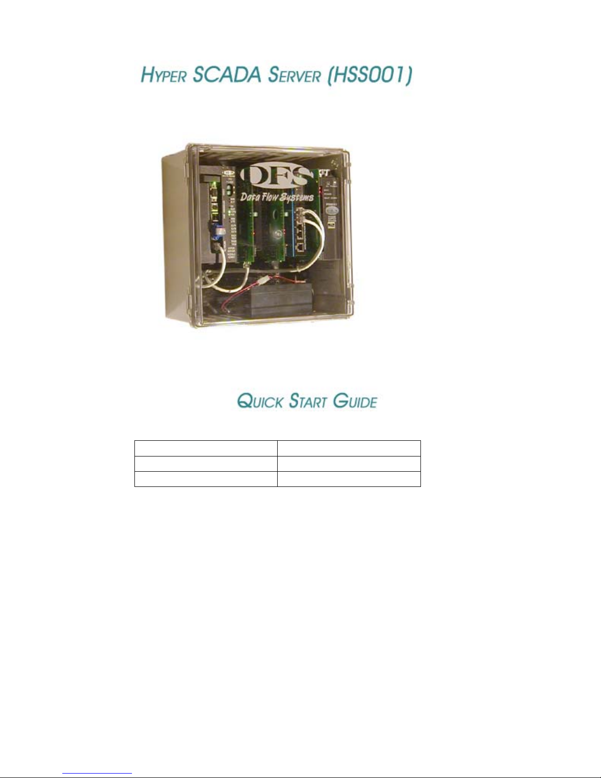
Connect HSS to LAN / Master Workstation
The HSS includes a NIM when using the unit’s COM ports to connect to serialtype devices. A FIM/NFM is required in place of a NIM when the unit is
connected to a Tunnel CTU.
When connecting the HSS to a local area network through a device such as a
hub, switch, or router, or to a dedicated master workstation, connect any
unused port on the NSM to a port on the other device.
HSS with NIM
H
S
M
0
0
1
12
TELEPHONE
LINES
N
I
M
0
0
1
AUDIO
OUT
N
S
M
0
0
1
COM2 COM1
P
4
S
3
M
2
0
1
0
3
AC
POWER
To Local Area Network/
Dedicated Master Workstation
4
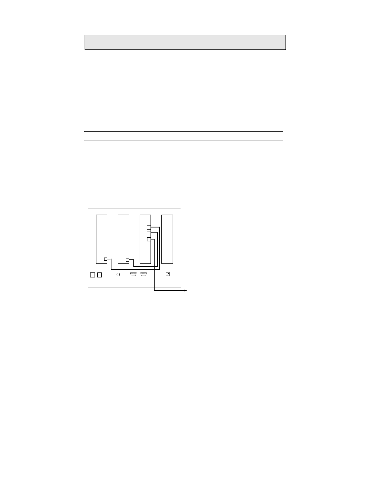
HSS with FIM/NFM
CAT5
HSS001 Quick Start Guide
1
TEL.
LINES
H
S
M
0
0
1
2
F
I
M
0
0
1
AUDIO
COM2 COM1
OUT
To Tunnel CTU
N
S
V
N
M
O
C
0
O
/
F
0
1
E
L
B
A
C
O
/
F
P
4
S
3
M
2
0
1
0
3
AC
POWER
To Local Area Network/
Dedicated Master Workstation
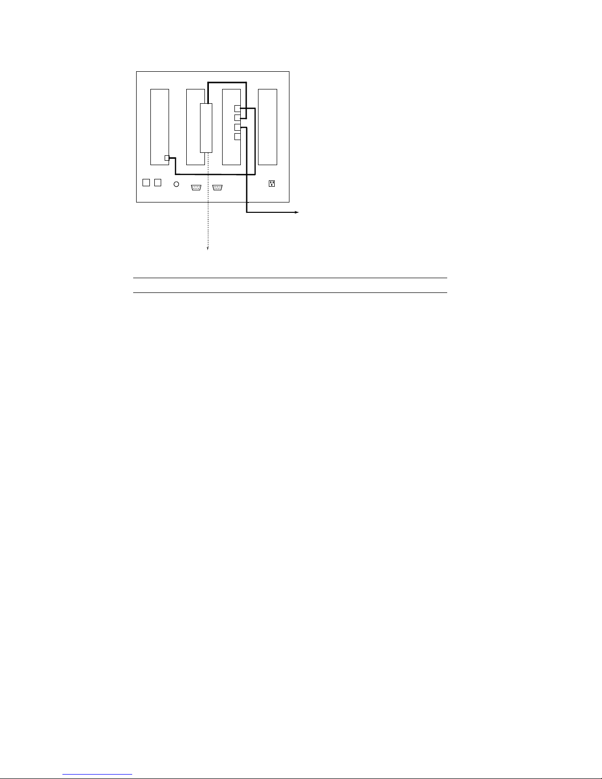
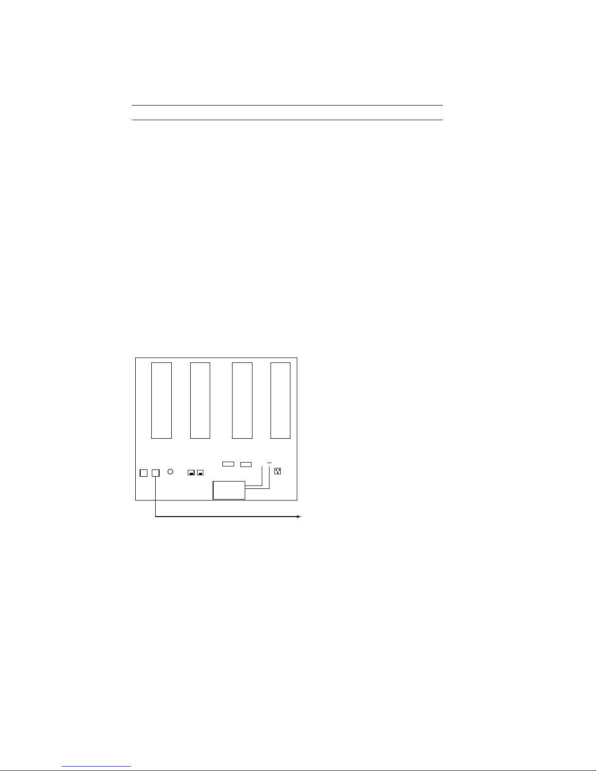
Connect the HSS to a Serial Device
The Hyper SCADA Server (HSS001) features two ports (COM1 and COM2) for
connecting serial-type devices, including Modbus devices. These ports are
connected to the HSS' NIM, which allows the serial devices to pass their data to
network devices. This is accomplished through a process called serial
tunneling. In serial tunneling, the HSM bundles serial data into network
packets and forwards it to the NIM. When the NIM sees an incoming packet, it
switches
to serial tunnel mode, extracts the serial data, and sends the data out the
appropriate COM port. When a serial device sends data to one of the NIM’s
COM ports, the NIM bundles the data into network packets and forwards them
to the HSM.
COM1 and COM2 include RTS and CTS to support connections to equipment
(such as radios and modems) that require hardware handshaking. RTS and
CTS are optionally enabled via configuration of the driver in HT3.
Additionally, both COM1 and COM2 are used as stand-alone serial tunnels
only; there is no bus communication.
5
HSS001 Quick Start Guide
COM1 and COM2:
Pin 2 = RXD
Pin 3 = TXD
Pin 5 = GND
Pin 7 = RTS
Pin 8 = CTS
To Serial Device 1
To Serial Device 2
12
TEL.
LINES
H
S
M
0
0
1
AUDIO
OUT
N
I
M
0
0
1
SOURCE
COM2 COM1
LOAD
BATTERY
N
S
M
0
0
1
P
S
M
0
0
3
+
AC
POWER
Configure the NIM’s IP Address
The HSS' NIM acts as an interface between the serial devices connected to the
HSS and the network. The NIM is referred to as a "tunneling device," because
its function is to pass - or tunnel - serial data through a network. As such, the
NIM requires a valid IP address.
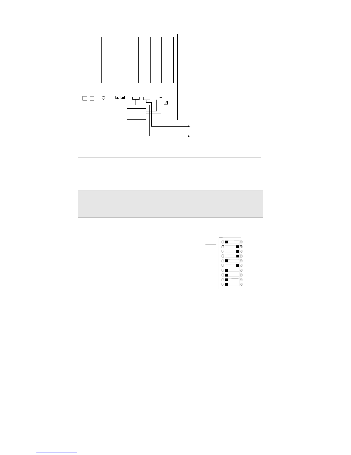
IMPORTANT: (1) The NIM cannot be addressed greater than 250. (2) The
ground (G) switch must remain in the ON position. (3) The BRAIN switch,
when set to the OFF position, allows an IP address to be configured when
using a NIM/FIM. Set the BRAIN switch to ON when using a NFM.
The NIM features automatic IP addressing. It
obtains the first three octets of its network
address from an HSM broadcast (a network
service called NIM Broadcast). The last octet
comes from the NIM Tunneling IP Address
block (located in the HSS to the left of the
NIM). The last octet is configured by placing
each of the DIP switches on the address block
either in the ON or OFF position. The address
is calculated by adding up the bits that are
OFF. The example at right shows the NIM
addressed at 208. The 128, 64, and 16 switches
have been placed in the OFF position (128 + 64
+16 = 208).
6
BRAIN
128
64
32
16
NIM TUNNELING
IP ADDRESS
G
8
4
2
1
ONO
F
F
HSS001 Quick Start Guide
When the NIM boots up, it receives a broadcast from the HSM that says, "This
is your subnet." The NIM reads its subnet, mates it with the tunnel address,
and begins to talk at that IP address.
Connect the HSS to a Telephone Line
Note: By default, HT3 software is configured for two phone lines. If only one
phone line is used for the call-in and call-out functions, HT3‘s configuration
must be changed. (See “Call In and Call Out: Configuring 911 & 411” in the
HT3 User Guide for more information.)
One Telephone Line Setup
This setup requires a configuration change in HT3.
Follow these instructions when using one telephone line for both the Call Out
and Call In functions.
Please note that if you are using only one line for both functions, call out (911)
takes precedence. Therefore, if you are calling in and an alarm occurs (one with
call out enabled), the system will disconnect your call in order to place the 911
call.
1. From your telephone room or telephone wall jack, locate the telephone
line's tip and ring wires and terminate them using an RJ11 modular plug.
2. Insert the plug into the LINE 2 jack. The LINE 2 jack is prewired to the
Line 2 termination points on the HSM’s card edge.
(See wiring diagram on next page.)
H
S
M
0
0
1
TEL.
AUDIO
LINES
OUT
12
CALL OUT (911) / CALL IN (411) LINE
N
I
M
0
0
1
ALARM
TERMINALS
LOAD
SOURCE
N
S
M
0
0
1
COM2 COM1
BATTERY
+
P
S
M
0
0
3
AC
POWER
7
To Wall Jack /
Telephone Room
 Loading...