


DD400 Series Restorer
User Guide
Software Version 3.1.2

Disclaimer
Notices
The information contained in this publication is subject to change without notice. Data Domain,
Incorporated makes no warranty of any kind with regard to this manual, including, but not limited
to, the implied warranties of merchantability and fitness for a particular purpose. Data Domain,
Incorporated shall not be liable for errors contained herein or for incidental or consequential
damages in connection with the furnishing, performance, or use of this manual.
NOTE: Data Domain hardware has been tested and found to comply with the limits for a Class A
digital device, pursuant to Part 15 of the FCC Rules.
This Class A digital apparatus complies with Canadian ICES-003.
Cet appareil numérique de la classe A est conforme à la norme NMB-0003 du Canada.
These limits are designed to provide reasonable protection against harmful interference when the
equipment is operated in a commercial environment. This equipment generates, uses, and can
radiate radio frequency energy and, if not installed and used in accordance with the instruction
manual, may cause harmful interference to radio communications. Operation of this equipment in a
residential area is likely to cause harmful interference in which case the user will be required to
correct the interference at his own expense.
Changes or modifications not expressly approved by Data Domain can void the user's authority to
operate the equipment.
Copyright
Copyright © 2005 Data Domain, Incorporated. All rights reserved. Data Domain, the Data Domain
logo, DD400 Series Restorer, Data Domain OS, Global Compression, Data Invulnerability
Architecture, and all other Data Domain product names and slogans are trademarks or registered
trademarks of Data Domain, Incorporated in the USA and/or other countries. Microsoft and
Windows are either registered trademarks or trademarks of Microsoft Corporation in the United
States and/or other countries. Portions of this product are software covered by the GNU General
Public License Copyright © 1989, 1991 by Free Software Foundation, Inc. Portions of this product
are software covered by the GNU Lesser General Public License Copyright © 1991, 1999 by Free
Software Foundation, Inc. Portions of this product are software covered by the GNU Free
Documentation License Copyright © 2000, 2001, 2002, by Free Software Foundation, Inc. Portions
of this product aresoftware Copyright © 1999 - 2003, by The OpenLDAP Foundation. Portions of
this product are software developed by the OpenSSL Project for use in the OpenSSL Toolkit
(http://www.openssl.org/), Copyright © 1998-2004 The OpenSSL Project, all rights reserved.
Portions of this product are Berkeley Software Distribution software, Copyright © 1988 - 2004 by
the Regents of the University of California, University of California, Berkeley. Portions of this
product are software Copyright © 1990 - 1999 by Sleepycat Software. Portions of this product are
software Copyright © 1985-2004 by the Massachusetts Institute of Technology. All rights reserved.
Portions of this product are LILO program code, Copyright © 1992 - 1998 Werner Almesberger.
All rights reserved. Portions of this product are software Copyright © 1999 - 2004 The Apache
Software Foundation, licensed under the Apache License, Version 2.0
(http://www.apache.org/licenses /LICENSE-2.0). Portions of this product are derived from

software Copyright © 1994, 1995, 1996, 1997, 1998, 1999, 2000, 2001, 2002 by Cold Spring
Harbor Laboratory. Funded under Grant P41-RR02188 by the National Institutes of Health.
Portions of this product are derived from software Copyright © 1996, 1997, 1998, 1999, 2000,
2001, 2002 byBoutell.Com, Inc. Portions of this product relating to GD2 format are derived from
software Copyright © 1999, 2000, 2001, 2002 Philip Warner. Portions of this product relating to
PNG are derived from software Copyright © 1999, 2000, 2001, 2002 Greg Roelofs. Portions of this
product relating to gdttf.c are derived from software Copyright © 1999, 2000, 2001, 2002 John
Ellson (ellson@lucent.com). Portions of this product relating to gdft.c are derived from software
Copyright © 2001, 2002 John Ellson (ellson@lucent.com). Portions of this product relating to
JPEG and to color quantization are derived from software Copyright © 2000,2001, 2002, Doug
Becker and copyright (C) 1994, 1995, 1996, 1997, 1998, 1999, 2000, 2001, 2002, Thomas G. Lane.
This software is based in part on the work of the Independent JPEG Group. Portions of this product
relating to WBMP are derived from software Copyright © 2000, 2001, 2002 Maurice Szmurlo and
Johan Van den Brande. Other product names and/or slogans mentioned herein may be trademarks
or registered trademarks of their respective companies.
Data Domain, Incorporated
3400 Hillview Ave.
Bldg. 3, 2nd Floor
Palo Alto, CA 94304
USA
Phone 650–565-7300
Fax 650–424-1057
www.datadomain.com
DD400 Series Release 3.1.2.0
October 31, 2005
Part number: 760-0301-0200 Rev. A


Contents
About This Guide . . . . . . . . . . . . . . . . . . . . . . . . . . . . . . . . . . . . . . . . . . . . . . . . . . . . . xix
Conventions . . . . . . . . . . . . . . . . . . . . . . . . . . . . . . . . . . . . . . . . . . . . . . . . . . . . . . . . . . . . . . . xx
Audience . . . . . . . . . . . . . . . . . . . . . . . . . . . . . . . . . . . . . . . . . . . . . . . . . . . . . . . . . . . . . . . . . xxi
Contacting Data Domain . . . . . . . . . . . . . . . . . . . . . . . . . . . . . . . . . . . . . . . . . . . . . . . . . . . . . xxi
Safety Warnings . . . . . . . . . . . . . . . . . . . . . . . . . . . . . . . . . . . . . . . . . . . . . . . . . . . . . . . . . . .xxii
Product Disposal Warning . . . . . . . . . . . . . . . . . . . . . . . . . . . . . . . . . . . . . . . . . . . . . . . .xxii
Qualified Personnel Warning . . . . . . . . . . . . . . . . . . . . . . . . . . . . . . . . . . . . . . . . . . . . . xxiii
Circuit Breaker (15A) Warning . . . . . . . . . . . . . . . . . . . . . . . . . . . . . . . . . . . . . . . . . . . xxiv
Grounded Equipment Warning . . . . . . . . . . . . . . . . . . . . . . . . . . . . . . . . . . . . . . . . . . . . .xxv
Ground Conductor Warning . . . . . . . . . . . . . . . . . . . . . . . . . . . . . . . . . . . . . . . . . . . . . .xxvii
Wrist Strap Warning . . . . . . . . . . . . . . . . . . . . . . . . . . . . . . . . . . . . . . . . . . . . . . . . . . . xxviii
Faceplates and Cover Panel Requirement . . . . . . . . . . . . . . . . . . . . . . . . . . . . . . . . . . . . xxix
Jewelry Removal Warning . . . . . . . . . . . . . . . . . . . . . . . . . . . . . . . . . . . . . . . . . . . . . . . xxxi
Class 1 Laser Product Warning . . . . . . . . . . . . . . . . . . . . . . . . . . . . . . . . . . . . . . . . . . . xxxiii
Invisible Laser Radiation Warning . . . . . . . . . . . . . . . . . . . . . . . . . . . . . . . . . . . . . . . . xxxiv
Regulatory Standards Compliance . . . . . . . . . . . . . . . . . . . . . . . . . . . . . . . . . . . . . . . . . . . . xxxv
EMC Environmental Conditions for Product to be Installed in the European Union . . . xxxv
(FCC) Class A Warning . . . . . . . . . . . . . . . . . . . . . . . . . . . . . . . . . . . . . . . . . . . . . . . . xxxvi
Canada Class A Warning . . . . . . . . . . . . . . . . . . . . . . . . . . . . . . . . . . . . . . . . . . . . . . . xxxvi
Japan (VCCI) Class A Warning . . . . . . . . . . . . . . . . . . . . . . . . . . . . . . . . . . . . . . . . . . xxxvi
Taiwan (BSMI) Class A Warning . . . . . . . . . . . . . . . . . . . . . . . . . . . . . . . . . . . . . . . . .xxxvii
v

Chapter 1: Introduction . . . . . . . . . . . . . . . . . . . . . . . . . . . . . . . . . . . . . . . . . . . . . . . . 1
DD400 Restorer Models . . . . . . . . . . . . . . . . . . . . . . . . . . . . . . . . . . . . . . . . . . . . . . . . . . . . . . 2
Applications that Send Data to a Restorer . . . . . . . . . . . . . . . . . . . . . . . . . . . . . . . . . . . . . . . . . 2
Data Integrity . . . . . . . . . . . . . . . . . . . . . . . . . . . . . . . . . . . . . . . . . . . . . . . . . . . . . . . . . . . . . . . 3
Data Compression . . . . . . . . . . . . . . . . . . . . . . . . . . . . . . . . . . . . . . . . . . . . . . . . . . . . . . . . . . . 3
Restore Operations . . . . . . . . . . . . . . . . . . . . . . . . . . . . . . . . . . . . . . . . . . . . . . . . . . . . . . . . . . . 4
Replicator . . . . . . . . . . . . . . . . . . . . . . . . . . . . . . . . . . . . . . . . . . . . . . . . . . . . . . . . . . . . . . . . . . 4
Restorer Hardware Interfaces . . . . . . . . . . . . . . . . . . . . . . . . . . . . . . . . . . . . . . . . . . . . . . . . . . . 4
Licensing . . . . . . . . . . . . . . . . . . . . . . . . . . . . . . . . . . . . . . . . . . . . . . . . . . . . . . . . . . . . . . . . . . 5
User Interfaces . . . . . . . . . . . . . . . . . . . . . . . . . . . . . . . . . . . . . . . . . . . . . . . . . . . . . . . . . . . . . . 5
Related Documentation . . . . . . . . . . . . . . . . . . . . . . . . . . . . . . . . . . . . . . . . . . . . . . . . . . . . . . . 5
Initial System Settings . . . . . . . . . . . . . . . . . . . . . . . . . . . . . . . . . . . . . . . . . . . . . . . . . . . . . . . . 5
Command Line Interface . . . . . . . . . . . . . . . . . . . . . . . . . . . . . . . . . . . . . . . . . . . . . . . . . . . . . . 7
Graphical User Interface . . . . . . . . . . . . . . . . . . . . . . . . . . . . . . . . . . . . . . . . . . . . . . . . . . . . . . 9
Hardware System-Level Interfaces . . . . . . . . . . . . . . . . . . . . . . . . . . . . . . . . . . . . . . . . . . . . . 11
Front Panel . . . . . . . . . . . . . . . . . . . . . . . . . . . . . . . . . . . . . . . . . . . . . . . . . . . . . . . . . . . . . 11
Back Panel . . . . . . . . . . . . . . . . . . . . . . . . . . . . . . . . . . . . . . . . . . . . . . . . . . . . . . . . . . . . . 12
Power Supply LEDs . . . . . . . . . . . . . . . . . . . . . . . . . . . . . . . . . . . . . . . . . . . . . . . . . . . 13
Hardware Interface . . . . . . . . . . . . . . . . . . . . . . . . . . . . . . . . . . . . . . . . . . . . . . . . . . . . 13
System Card Interface . . . . . . . . . . . . . . . . . . . . . . . . . . . . . . . . . . . . . . . . . . . . . . . . . 14
Chapter 2: Disk Space and Backup Software . . . . . . . . . . . . . . . . . . . . . . . . . . . . . . 17
Space Management . . . . . . . . . . . . . . . . . . . . . . . . . . . . . . . . . . . . . . . . . . . . . . . . . . . . . . . . . 17
Estimate Use of Disk Space . . . . . . . . . . . . . . . . . . . . . . . . . . . . . . . . . . . . . . . . . . . . . . . . . . . 18
Reclaim Data Storage Disk Space . . . . . . . . . . . . . . . . . . . . . . . . . . . . . . . . . . . . . . . . . . . . . . 19
Manage File System Use of Disk Space . . . . . . . . . . . . . . . . . . . . . . . . . . . . . . . . . . . . . . . . . 19
Display the Space Usage Graphs . . . . . . . . . . . . . . . . . . . . . . . . . . . . . . . . . . . . . . . . . . . . . . . 21
Chapter 3: Installation . . . . . . . . . . . . . . . . . . . . . . . . . . . . . . . . . . . . . . . . . . . . . . . . 23
Site Requirements . . . . . . . . . . . . . . . . . . . . . . . . . . . . . . . . . . . . . . . . . . . . . . . . . . . . . . . . . . 24
Hardware Installation . . . . . . . . . . . . . . . . . . . . . . . . . . . . . . . . . . . . . . . . . . . . . . . . . . . . . . . . 25
vi DD400 Series Restorer User Guide

Backup Software Requirements . . . . . . . . . . . . . . . . . . . . . . . . . . . . . . . . . . . . . . . . . . . . . . . . 28
CIFS Backup Server Timeout . . . . . . . . . . . . . . . . . . . . . . . . . . . . . . . . . . . . . . . . . . . . . . . . . . 28
DHCP Server . . . . . . . . . . . . . . . . . . . . . . . . . . . . . . . . . . . . . . . . . . . . . . . . . . . . . . . . . . . . . . 28
Login and Configuration . . . . . . . . . . . . . . . . . . . . . . . . . . . . . . . . . . . . . . . . . . . . . . . . . . . . . . 29
Additional Configuration . . . . . . . . . . . . . . . . . . . . . . . . . . . . . . . . . . . . . . . . . . . . . . . . . . . . . 40
Administering a Restorer . . . . . . . . . . . . . . . . . . . . . . . . . . . . . . . . . . . . . . . . . . . . . . . . . . . . .41
Command Line Interface . . . . . . . . . . . . . . . . . . . . . . . . . . . . . . . . . . . . . . . . . . . . . . . . . . . 41
DDR Manager . . . . . . . . . . . . . . . . . . . . . . . . . . . . . . . . . . . . . . . . . . . . . . . . . . . . . . . . . . .41
Chapter 4: DD400g Gateway . . . . . . . . . . . . . . . . . . . . . . . . . . . . . . . . . . . . . . . . . . . .43
Command Changes . . . . . . . . . . . . . . . . . . . . . . . . . . . . . . . . . . . . . . . . . . . . . . . . . . . . . . . . . . 44
Installation . . . . . . . . . . . . . . . . . . . . . . . . . . . . . . . . . . . . . . . . . . . . . . . . . . . . . . . . . . . . . . . . . 47
Troubleshooting . . . . . . . . . . . . . . . . . . . . . . . . . . . . . . . . . . . . . . . . . . . . . . . . . . . . . . . . . . . . 49
Chapter 5: Configuration Management . . . . . . . . . . . . . . . . . . . . . . . . . . . . . . . . . . . 51
The Config Command . . . . . . . . . . . . . . . . . . . . . . . . . . . . . . . . . . . . . . . . . . . . . . . . . . . . . . . .51
Change Configuration Settings . . . . . . . . . . . . . . . . . . . . . . . . . . . . . . . . . . . . . . . . . . . . . . 51
Save and Return a Configuration . . . . . . . . . . . . . . . . . . . . . . . . . . . . . . . . . . . . . . . . . . . . 52
Reset the Location Description . . . . . . . . . . . . . . . . . . . . . . . . . . . . . . . . . . . . . . . . . . . . . . 52
Reset the Mail Server to a Null Entry . . . . . . . . . . . . . . . . . . . . . . . . . . . . . . . . . . . . . . . . . 52
Reset the Time Zone to the Default . . . . . . . . . . . . . . . . . . . . . . . . . . . . . . . . . . . . . . . . . . 53
Set an Administrative Email Address . . . . . . . . . . . . . . . . . . . . . . . . . . . . . . . . . . . . . . . . . 53
Set an Administrative Host Name . . . . . . . . . . . . . . . . . . . . . . . . . . . . . . . . . . . . . . . . . . . .53
Change the System Location Description . . . . . . . . . . . . . . . . . . . . . . . . . . . . . . . . . . . . . . 53
Change the Mail Server Hostname . . . . . . . . . . . . . . . . . . . . . . . . . . . . . . . . . . . . . . . . . . . 54
Set a Time Zone for the System Clock . . . . . . . . . . . . . . . . . . . . . . . . . . . . . . . . . . . . . . . .54
Display the Administrative Email Address . . . . . . . . . . . . . . . . . . . . . . . . . . . . . . . . . . . . .55
Display the Administrative Host Name . . . . . . . . . . . . . . . . . . . . . . . . . . . . . . . . . . . . . . .55
Display the System Location Description . . . . . . . . . . . . . . . . . . . . . . . . . . . . . . . . . . . . . . 55
Display the Mail Server Hostname . . . . . . . . . . . . . . . . . . . . . . . . . . . . . . . . . . . . . . . . . . .55
Display the Time Zone for the System Clock . . . . . . . . . . . . . . . . . . . . . . . . . . . . . . . . . . . 56
Contents vii

The License Command . . . . . . . . . . . . . . . . . . . . . . . . . . . . . . . . . . . . . . . . . . . . . . . . . . . . . . 56
Add a License . . . . . . . . . . . . . . . . . . . . . . . . . . . . . . . . . . . . . . . . . . . . . . . . . . . . . . . . . . . 56
Remove All Feature Licenses . . . . . . . . . . . . . . . . . . . . . . . . . . . . . . . . . . . . . . . . . . . . . . . 56
Remove a License . . . . . . . . . . . . . . . . . . . . . . . . . . . . . . . . . . . . . . . . . . . . . . . . . . . . . . . 57
Display Licenses . . . . . . . . . . . . . . . . . . . . . . . . . . . . . . . . . . . . . . . . . . . . . . . . . . . . . . . . . 57
Chapter 6: Access Control for Administration . . . . . . . . . . . . . . . . . . . . . . . . . . . . . 59
Add a Host . . . . . . . . . . . . . . . . . . . . . . . . . . . . . . . . . . . . . . . . . . . . . . . . . . . . . . . . . . . . . . . . 59
Remove a Host . . . . . . . . . . . . . . . . . . . . . . . . . . . . . . . . . . . . . . . . . . . . . . . . . . . . . . . . . . . . . 59
Enable a Protocol . . . . . . . . . . . . . . . . . . . . . . . . . . . . . . . . . . . . . . . . . . . . . . . . . . . . . . . . . . . 60
Disable a Protocol . . . . . . . . . . . . . . . . . . . . . . . . . . . . . . . . . . . . . . . . . . . . . . . . . . . . . . . . . . 60
Reset System Access . . . . . . . . . . . . . . . . . . . . . . . . . . . . . . . . . . . . . . . . . . . . . . . . . . . . . . . . 60
Add an Authorized SSH Public Key . . . . . . . . . . . . . . . . . . . . . . . . . . . . . . . . . . . . . . . . . . . . 60
Remove an SSH Key File Entry . . . . . . . . . . . . . . . . . . . . . . . . . . . . . . . . . . . . . . . . . . . . . . . 61
Remove the SSH Key File . . . . . . . . . . . . . . . . . . . . . . . . . . . . . . . . . . . . . . . . . . . . . . . . . . . . 61
Create a New HTTPS Certificate . . . . . . . . . . . . . . . . . . . . . . . . . . . . . . . . . . . . . . . . . . . . . . . 61
Display the SSH Key File . . . . . . . . . . . . . . . . . . . . . . . . . . . . . . . . . . . . . . . . . . . . . . . . . . . . 62
Display Hosts and Status . . . . . . . . . . . . . . . . . . . . . . . . . . . . . . . . . . . . . . . . . . . . . . . . . . . . . 62
Return Command Output to a Remote machine . . . . . . . . . . . . . . . . . . . . . . . . . . . . . . . . . . . 62
Chapter 7: User Administration . . . . . . . . . . . . . . . . . . . . . . . . . . . . . . . . . . . . . . . . . 65
Add a User . . . . . . . . . . . . . . . . . . . . . . . . . . . . . . . . . . . . . . . . . . . . . . . . . . . . . . . . . . . . . . . . 65
Remove a User . . . . . . . . . . . . . . . . . . . . . . . . . . . . . . . . . . . . . . . . . . . . . . . . . . . . . . . . . . . . . 65
Change a Password . . . . . . . . . . . . . . . . . . . . . . . . . . . . . . . . . . . . . . . . . . . . . . . . . . . . . . . . . 66
Reset to the Default User . . . . . . . . . . . . . . . . . . . . . . . . . . . . . . . . . . . . . . . . . . . . . . . . . . . . . 66
Display Current Users . . . . . . . . . . . . . . . . . . . . . . . . . . . . . . . . . . . . . . . . . . . . . . . . . . . . . . . 66
Display All Users . . . . . . . . . . . . . . . . . . . . . . . . . . . . . . . . . . . . . . . . . . . . . . . . . . . . . . . . . . . 67
Chapter 8: Alerts and System Reports . . . . . . . . . . . . . . . . . . . . . . . . . . . . . . . . . . . 69
Alerts . . . . . . . . . . . . . . . . . . . . . . . . . . . . . . . . . . . . . . . . . . . . . . . . . . . . . . . . . . . . . . . . . . . . 70
Add to the Email List . . . . . . . . . . . . . . . . . . . . . . . . . . . . . . . . . . . . . . . . . . . . . . . . . . . . . 70
Test the Email List . . . . . . . . . . . . . . . . . . . . . . . . . . . . . . . . . . . . . . . . . . . . . . . . . . . . . . . 70
viii DD400 Series Restorer User Guide

Remove from the Email List . . . . . . . . . . . . . . . . . . . . . . . . . . . . . . . . . . . . . . . . . . . . . . . . 70
Reset the Email List . . . . . . . . . . . . . . . . . . . . . . . . . . . . . . . . . . . . . . . . . . . . . . . . . . . . . .71
Display Current Alerts . . . . . . . . . . . . . . . . . . . . . . . . . . . . . . . . . . . . . . . . . . . . . . . . . . . . 71
Display the Alerts History . . . . . . . . . . . . . . . . . . . . . . . . . . . . . . . . . . . . . . . . . . . . . . . . . . 72
Display the Email List . . . . . . . . . . . . . . . . . . . . . . . . . . . . . . . . . . . . . . . . . . . . . . . . . . . . .72
Display Current Alerts and Recent History . . . . . . . . . . . . . . . . . . . . . . . . . . . . . . . . . . . . 73
Display the Email List and Administrator Email . . . . . . . . . . . . . . . . . . . . . . . . . . . . . . . . 73
Autosupport Reports . . . . . . . . . . . . . . . . . . . . . . . . . . . . . . . . . . . . . . . . . . . . . . . . . . . . . . . . . 74
Add to the Email List . . . . . . . . . . . . . . . . . . . . . . . . . . . . . . . . . . . . . . . . . . . . . . . . . . . . .74
Remove from the Email List . . . . . . . . . . . . . . . . . . . . . . . . . . . . . . . . . . . . . . . . . . . . . . . . 74
Reset the Email List . . . . . . . . . . . . . . . . . . . . . . . . . . . . . . . . . . . . . . . . . . . . . . . . . . . . . .74
Test the Autosupport Report Email List . . . . . . . . . . . . . . . . . . . . . . . . . . . . . . . . . . . . . . . 74
Set the Schedule . . . . . . . . . . . . . . . . . . . . . . . . . . . . . . . . . . . . . . . . . . . . . . . . . . . . . . . . . 75
Reset the Schedule . . . . . . . . . . . . . . . . . . . . . . . . . . . . . . . . . . . . . . . . . . . . . . . . . . . . . . .75
Reset the Schedule and the List . . . . . . . . . . . . . . . . . . . . . . . . . . . . . . . . . . . . . . . . . . . . .76
Run the Autosupport Report . . . . . . . . . . . . . . . . . . . . . . . . . . . . . . . . . . . . . . . . . . . . . . . . 76
Display all Autosupport Parameters . . . . . . . . . . . . . . . . . . . . . . . . . . . . . . . . . . . . . . . . . . 76
Display the Autosupport Report Schedule . . . . . . . . . . . . . . . . . . . . . . . . . . . . . . . . . . . . . 77
Display the Autosupport Email List . . . . . . . . . . . . . . . . . . . . . . . . . . . . . . . . . . . . . . . . . .77
Display the Autosupport History . . . . . . . . . . . . . . . . . . . . . . . . . . . . . . . . . . . . . . . . . . . . 78
Hourly System Status . . . . . . . . . . . . . . . . . . . . . . . . . . . . . . . . . . . . . . . . . . . . . . . . . . . . . . . . 78
Chapter 9: File System Management . . . . . . . . . . . . . . . . . . . . . . . . . . . . . . . . . . . . . 79
Statistics and Basic Operations . . . . . . . . . . . . . . . . . . . . . . . . . . . . . . . . . . . . . . . . . . . . . . . . .79
Start the Restorer File System Process . . . . . . . . . . . . . . . . . . . . . . . . . . . . . . . . . . . . . . . . 79
Stop the Restorer File System Process . . . . . . . . . . . . . . . . . . . . . . . . . . . . . . . . . . . . . . . . 79
Delete All Data in the File System . . . . . . . . . . . . . . . . . . . . . . . . . . . . . . . . . . . . . . . . . . . 79
Display File System Status . . . . . . . . . . . . . . . . . . . . . . . . . . . . . . . . . . . . . . . . . . . . . . . . . 80
Display File System Uptime . . . . . . . . . . . . . . . . . . . . . . . . . . . . . . . . . . . . . . . . . . . . . . . . 80
Display File System Space Utilization . . . . . . . . . . . . . . . . . . . . . . . . . . . . . . . . . . . . . . . . 81
Display Compression . . . . . . . . . . . . . . . . . . . . . . . . . . . . . . . . . . . . . . . . . . . . . . . . . . . . . 82
Contents ix

Clean Operations . . . . . . . . . . . . . . . . . . . . . . . . . . . . . . . . . . . . . . . . . . . . . . . . . . . . . . . . . . . 83
Start Cleaning . . . . . . . . . . . . . . . . . . . . . . . . . . . . . . . . . . . . . . . . . . . . . . . . . . . . . . . . . . . 84
Stop Cleaning . . . . . . . . . . . . . . . . . . . . . . . . . . . . . . . . . . . . . . . . . . . . . . . . . . . . . . . . . . . 85
Change the Schedule . . . . . . . . . . . . . . . . . . . . . . . . . . . . . . . . . . . . . . . . . . . . . . . . . . . . . 85
Set the Schedule or Throttle to the Default . . . . . . . . . . . . . . . . . . . . . . . . . . . . . . . . . . . . 86
Set the Run Time or Gigabytes Cleaned . . . . . . . . . . . . . . . . . . . . . . . . . . . . . . . . . . . . . . 86
Set Network Bandwidth Used . . . . . . . . . . . . . . . . . . . . . . . . . . . . . . . . . . . . . . . . . . . . . . 87
Update Statistics . . . . . . . . . . . . . . . . . . . . . . . . . . . . . . . . . . . . . . . . . . . . . . . . . . . . . . . . . 87
Display the Amount Parameters . . . . . . . . . . . . . . . . . . . . . . . . . . . . . . . . . . . . . . . . . . . . . 87
Display All Clean Parameters . . . . . . . . . . . . . . . . . . . . . . . . . . . . . . . . . . . . . . . . . . . . . . 88
Display the Schedule . . . . . . . . . . . . . . . . . . . . . . . . . . . . . . . . . . . . . . . . . . . . . . . . . . . . . 88
Display the Throttle Setting . . . . . . . . . . . . . . . . . . . . . . . . . . . . . . . . . . . . . . . . . . . . . . . . 88
Display the Clean Operation Status . . . . . . . . . . . . . . . . . . . . . . . . . . . . . . . . . . . . . . . . . . 88
Display Recommended Cleaning Times . . . . . . . . . . . . . . . . . . . . . . . . . . . . . . . . . . . . . . 89
Chapter 10: Disk Management . . . . . . . . . . . . . . . . . . . . . . . . . . . . . . . . . . . . . . . . . . 91
Fail a Disk . . . . . . . . . . . . . . . . . . . . . . . . . . . . . . . . . . . . . . . . . . . . . . . . . . . . . . . . . . . . . . . . 91
Unfail a Disk . . . . . . . . . . . . . . . . . . . . . . . . . . . . . . . . . . . . . . . . . . . . . . . . . . . . . . . . . . . . . . 92
Check All Disks . . . . . . . . . . . . . . . . . . . . . . . . . . . . . . . . . . . . . . . . . . . . . . . . . . . . . . . . . . . . 92
Identify a Physical Disk in the Chassis . . . . . . . . . . . . . . . . . . . . . . . . . . . . . . . . . . . . . . . . . . 92
Display Disk Status . . . . . . . . . . . . . . . . . . . . . . . . . . . . . . . . . . . . . . . . . . . . . . . . . . . . . . . . . 92
Display Disk Type and Capacity Information . . . . . . . . . . . . . . . . . . . . . . . . . . . . . . . . . . . . . 93
Display RAID Status for Disks . . . . . . . . . . . . . . . . . . . . . . . . . . . . . . . . . . . . . . . . . . . . . . . . 94
Display Detailed RAID Information . . . . . . . . . . . . . . . . . . . . . . . . . . . . . . . . . . . . . . . . . . . . 95
Display Disk Performance Details . . . . . . . . . . . . . . . . . . . . . . . . . . . . . . . . . . . . . . . . . . . . . . 97
Reset Disk Performance Statistics . . . . . . . . . . . . . . . . . . . . . . . . . . . . . . . . . . . . . . . . . . . . . . 98
Display Disk Reliability Details . . . . . . . . . . . . . . . . . . . . . . . . . . . . . . . . . . . . . . . . . . . . . . . 98
Display Disk Debug Information . . . . . . . . . . . . . . . . . . . . . . . . . . . . . . . . . . . . . . . . . . . . . . . 99
Display the History of Disk Failures . . . . . . . . . . . . . . . . . . . . . . . . . . . . . . . . . . . . . . . . . . . . 99
x DD400 Series Restorer User Guide

Chapter 11: System Maintenance . . . . . . . . . . . . . . . . . . . . . . . . . . . . . . . . . . . . . . . 101
The System Command . . . . . . . . . . . . . . . . . . . . . . . . . . . . . . . . . . . . . . . . . . . . . . . . . . . . . .101
Shut down the Restorer Hardware . . . . . . . . . . . . . . . . . . . . . . . . . . . . . . . . . . . . . . . . . .101
Reboot the Restorer . . . . . . . . . . . . . . . . . . . . . . . . . . . . . . . . . . . . . . . . . . . . . . . . . . . . . . 102
Upgrade the Restorer Software . . . . . . . . . . . . . . . . . . . . . . . . . . . . . . . . . . . . . . . . . . . . .102
To upgrade from the Data Domain web site . . . . . . . . . . . . . . . . . . . . . . . . . . . . . . . . 102
To upgrade using FTP . . . . . . . . . . . . . . . . . . . . . . . . . . . . . . . . . . . . . . . . . . . . . . . . . 103
Set the Date and Time . . . . . . . . . . . . . . . . . . . . . . . . . . . . . . . . . . . . . . . . . . . . . . . . . . . . 103
Display the Restorer Serial Number . . . . . . . . . . . . . . . . . . . . . . . . . . . . . . . . . . . . . . . . . 104
Display Fan Status . . . . . . . . . . . . . . . . . . . . . . . . . . . . . . . . . . . . . . . . . . . . . . . . . . . . . . .104
Display System Statistics . . . . . . . . . . . . . . . . . . . . . . . . . . . . . . . . . . . . . . . . . . . . . . . . . 105
Display System Uptime . . . . . . . . . . . . . . . . . . . . . . . . . . . . . . . . . . . . . . . . . . . . . . . . . . . 105
Display Detailed System Statistics . . . . . . . . . . . . . . . . . . . . . . . . . . . . . . . . . . . . . . . . . . 106
Display the Restorer Model Number . . . . . . . . . . . . . . . . . . . . . . . . . . . . . . . . . . . . . . . .107
Display System Status . . . . . . . . . . . . . . . . . . . . . . . . . . . . . . . . . . . . . . . . . . . . . . . . . . . .108
Display Data Transfer Performance . . . . . . . . . . . . . . . . . . . . . . . . . . . . . . . . . . . . . . . . . 109
Display the Data Domain OS Version . . . . . . . . . . . . . . . . . . . . . . . . . . . . . . . . . . . . . . . 110
Display the Date and Time . . . . . . . . . . . . . . . . . . . . . . . . . . . . . . . . . . . . . . . . . . . . . . . . 110
Display All System Information . . . . . . . . . . . . . . . . . . . . . . . . . . . . . . . . . . . . . . . . . . . . 111
The Alias Command . . . . . . . . . . . . . . . . . . . . . . . . . . . . . . . . . . . . . . . . . . . . . . . . . . . . . . . .111
Add an Alias . . . . . . . . . . . . . . . . . . . . . . . . . . . . . . . . . . . . . . . . . . . . . . . . . . . . . . . . . . .111
Remove an Alias . . . . . . . . . . . . . . . . . . . . . . . . . . . . . . . . . . . . . . . . . . . . . . . . . . . . . . . . 111
Reset Aliases . . . . . . . . . . . . . . . . . . . . . . . . . . . . . . . . . . . . . . . . . . . . . . . . . . . . . . . . . . . 111
Display Aliases . . . . . . . . . . . . . . . . . . . . . . . . . . . . . . . . . . . . . . . . . . . . . . . . . . . . . . . . .112
Time Servers and the NTP Command . . . . . . . . . . . . . . . . . . . . . . . . . . . . . . . . . . . . . . . . . . 112
Enable NTP Service . . . . . . . . . . . . . . . . . . . . . . . . . . . . . . . . . . . . . . . . . . . . . . . . . . . . .112
Disable NTP Service . . . . . . . . . . . . . . . . . . . . . . . . . . . . . . . . . . . . . . . . . . . . . . . . . . . . . 113
Add a Time Server . . . . . . . . . . . . . . . . . . . . . . . . . . . . . . . . . . . . . . . . . . . . . . . . . . . . . . 113
Delete a Time Server . . . . . . . . . . . . . . . . . . . . . . . . . . . . . . . . . . . . . . . . . . . . . . . . . . . . . 113
Reset the List to Multicast . . . . . . . . . . . . . . . . . . . . . . . . . . . . . . . . . . . . . . . . . . . . . . . . . 113
Contents xi

Reset All NTP Settings . . . . . . . . . . . . . . . . . . . . . . . . . . . . . . . . . . . . . . . . . . . . . . . . . . . 113
Display NTP Status . . . . . . . . . . . . . . . . . . . . . . . . . . . . . . . . . . . . . . . . . . . . . . . . . . . . . 114
Display NTP Settings . . . . . . . . . . . . . . . . . . . . . . . . . . . . . . . . . . . . . . . . . . . . . . . . . . . . 114
Chapter 12: Network Management . . . . . . . . . . . . . . . . . . . . . . . . . . . . . . . . . . . . . 115
The Net Command . . . . . . . . . . . . . . . . . . . . . . . . . . . . . . . . . . . . . . . . . . . . . . . . . . . . . . . . . 115
Enable an Interface . . . . . . . . . . . . . . . . . . . . . . . . . . . . . . . . . . . . . . . . . . . . . . . . . . . . . . 115
Disable an Interface . . . . . . . . . . . . . . . . . . . . . . . . . . . . . . . . . . . . . . . . . . . . . . . . . . . . . 115
Enable DHCP . . . . . . . . . . . . . . . . . . . . . . . . . . . . . . . . . . . . . . . . . . . . . . . . . . . . . . . . . . 116
Disable DHCP . . . . . . . . . . . . . . . . . . . . . . . . . . . . . . . . . . . . . . . . . . . . . . . . . . . . . . . . . 116
Change an Interface Netmask . . . . . . . . . . . . . . . . . . . . . . . . . . . . . . . . . . . . . . . . . . . . . . 116
Change an Interface Transfer Unit Size . . . . . . . . . . . . . . . . . . . . . . . . . . . . . . . . . . . . . . 117
Add or Change DNS servers . . . . . . . . . . . . . . . . . . . . . . . . . . . . . . . . . . . . . . . . . . . . . . 117
Ping a Host . . . . . . . . . . . . . . . . . . . . . . . . . . . . . . . . . . . . . . . . . . . . . . . . . . . . . . . . . . . . 117
Change the Restorer Hostname . . . . . . . . . . . . . . . . . . . . . . . . . . . . . . . . . . . . . . . . . . . . 118
Change an Interface IP Address . . . . . . . . . . . . . . . . . . . . . . . . . . . . . . . . . . . . . . . . . . . . 118
Change the Domain Name . . . . . . . . . . . . . . . . . . . . . . . . . . . . . . . . . . . . . . . . . . . . . . . . 118
Add a Hostname/IP Address to the /etc/hosts File . . . . . . . . . . . . . . . . . . . . . . . . . . . . . . 118
Reset Network Parameters . . . . . . . . . . . . . . . . . . . . . . . . . . . . . . . . . . . . . . . . . . . . . . . . 119
Set Interface Duplex Line Use . . . . . . . . . . . . . . . . . . . . . . . . . . . . . . . . . . . . . . . . . . . . . 119
Set Interface Line Speed . . . . . . . . . . . . . . . . . . . . . . . . . . . . . . . . . . . . . . . . . . . . . . . . . . 119
Set Autonegotiate for an Interface . . . . . . . . . . . . . . . . . . . . . . . . . . . . . . . . . . . . . . . . . . 120
Delete a Hostname/IP address from the /etc/hosts File . . . . . . . . . . . . . . . . . . . . . . . . . . 120
Delete all Hostname/IP addresses from the /etc/hosts File . . . . . . . . . . . . . . . . . . . . . . . 120
Display Hostname/IP addresses from the /etc/hosts File . . . . . . . . . . . . . . . . . . . . . . . . . 120
Display an Ethernet Interface Configuration . . . . . . . . . . . . . . . . . . . . . . . . . . . . . . . . . . 121
Display Interface Settings . . . . . . . . . . . . . . . . . . . . . . . . . . . . . . . . . . . . . . . . . . . . . . . . 121
Display Ethernet Hardware Information . . . . . . . . . . . . . . . . . . . . . . . . . . . . . . . . . . . . . 122
Display the Restorer Hostname . . . . . . . . . . . . . . . . . . . . . . . . . . . . . . . . . . . . . . . . . . . . 123
Display the Domain Name Used for Email . . . . . . . . . . . . . . . . . . . . . . . . . . . . . . . . . . . 123
Display DNS Servers . . . . . . . . . . . . . . . . . . . . . . . . . . . . . . . . . . . . . . . . . . . . . . . . . . . . 124
xii DD400 Series Restorer User Guide

Display Network Statistics . . . . . . . . . . . . . . . . . . . . . . . . . . . . . . . . . . . . . . . . . . . . . . . . 124
Display All Networking Information . . . . . . . . . . . . . . . . . . . . . . . . . . . . . . . . . . . . . . . . 125
The Route Command . . . . . . . . . . . . . . . . . . . . . . . . . . . . . . . . . . . . . . . . . . . . . . . . . . . . . . .125
Add a Routing Rule . . . . . . . . . . . . . . . . . . . . . . . . . . . . . . . . . . . . . . . . . . . . . . . . . . . . . . 125
Remove a Routing Rule . . . . . . . . . . . . . . . . . . . . . . . . . . . . . . . . . . . . . . . . . . . . . . . . . . 126
Change the Routing Default Gateway . . . . . . . . . . . . . . . . . . . . . . . . . . . . . . . . . . . . . . . . 126
Reset the Default Routing Gateway . . . . . . . . . . . . . . . . . . . . . . . . . . . . . . . . . . . . . . . . .126
Display a Route . . . . . . . . . . . . . . . . . . . . . . . . . . . . . . . . . . . . . . . . . . . . . . . . . . . . . . . . .127
Display the Configured Static Routes . . . . . . . . . . . . . . . . . . . . . . . . . . . . . . . . . . . . . . . . 127
Display the Kernel IP Routing Table . . . . . . . . . . . . . . . . . . . . . . . . . . . . . . . . . . . . . . . . 127
Display the Default Routing Gateway . . . . . . . . . . . . . . . . . . . . . . . . . . . . . . . . . . . . . . . 128
Chapter 13: NFS Management . . . . . . . . . . . . . . . . . . . . . . . . . . . . . . . . . . . . . . . . . .129
Add NFS Clients . . . . . . . . . . . . . . . . . . . . . . . . . . . . . . . . . . . . . . . . . . . . . . . . . . . . . . . . . . . 129
Remove Clients . . . . . . . . . . . . . . . . . . . . . . . . . . . . . . . . . . . . . . . . . . . . . . . . . . . . . . . . . . . . 130
Enable Clients . . . . . . . . . . . . . . . . . . . . . . . . . . . . . . . . . . . . . . . . . . . . . . . . . . . . . . . . . . . . . 130
Disable Clients . . . . . . . . . . . . . . . . . . . . . . . . . . . . . . . . . . . . . . . . . . . . . . . . . . . . . . . . . . . .130
Reset Clients to the Default . . . . . . . . . . . . . . . . . . . . . . . . . . . . . . . . . . . . . . . . . . . . . . . . . .131
Clear the NFS Statistics . . . . . . . . . . . . . . . . . . . . . . . . . . . . . . . . . . . . . . . . . . . . . . . . . . . . . 131
Display Active Clients . . . . . . . . . . . . . . . . . . . . . . . . . . . . . . . . . . . . . . . . . . . . . . . . . . . . . . 131
Display Allowed Clients . . . . . . . . . . . . . . . . . . . . . . . . . . . . . . . . . . . . . . . . . . . . . . . . . . . . .131
Display Statistics . . . . . . . . . . . . . . . . . . . . . . . . . . . . . . . . . . . . . . . . . . . . . . . . . . . . . . . . . . .132
Display Detailed Statistics . . . . . . . . . . . . . . . . . . . . . . . . . . . . . . . . . . . . . . . . . . . . . . . . . . . 133
Display Status . . . . . . . . . . . . . . . . . . . . . . . . . . . . . . . . . . . . . . . . . . . . . . . . . . . . . . . . . . . . .133
Display Timing for NFS Operations . . . . . . . . . . . . . . . . . . . . . . . . . . . . . . . . . . . . . . . . . . . . 134
Chapter 14: CIFS Management . . . . . . . . . . . . . . . . . . . . . . . . . . . . . . . . . . . . . . . . .135
Access from Windows to a Restorer . . . . . . . . . . . . . . . . . . . . . . . . . . . . . . . . . . . . . . . . . . . . 135
Add a User . . . . . . . . . . . . . . . . . . . . . . . . . . . . . . . . . . . . . . . . . . . . . . . . . . . . . . . . . . . . . 135
Add a Client . . . . . . . . . . . . . . . . . . . . . . . . . . . . . . . . . . . . . . . . . . . . . . . . . . . . . . . . . . .136
Contents xiii

CIFS Command . . . . . . . . . . . . . . . . . . . . . . . . . . . . . . . . . . . . . . . . . . . . . . . . . . . . . . . . . . . 136
Enable Client Connections . . . . . . . . . . . . . . . . . . . . . . . . . . . . . . . . . . . . . . . . . . . . . . . . 136
Disable Client Connections . . . . . . . . . . . . . . . . . . . . . . . . . . . . . . . . . . . . . . . . . . . . . . . 136
Add a Backup Client . . . . . . . . . . . . . . . . . . . . . . . . . . . . . . . . . . . . . . . . . . . . . . . . . . . . 136
Add an Administrative Client . . . . . . . . . . . . . . . . . . . . . . . . . . . . . . . . . . . . . . . . . . . . . . 137
Remove a Backup Client . . . . . . . . . . . . . . . . . . . . . . . . . . . . . . . . . . . . . . . . . . . . . . . . . 137
Remove an Administrative Client . . . . . . . . . . . . . . . . . . . . . . . . . . . . . . . . . . . . . . . . . . 137
Remove All CIFS Clients . . . . . . . . . . . . . . . . . . . . . . . . . . . . . . . . . . . . . . . . . . . . . . . . . 137
Set a NetBIOS Hostname . . . . . . . . . . . . . . . . . . . . . . . . . . . . . . . . . . . . . . . . . . . . . . . . . 138
Remove the NetBIOS Hostname . . . . . . . . . . . . . . . . . . . . . . . . . . . . . . . . . . . . . . . . . . . 138
Set the Authentication Mode . . . . . . . . . . . . . . . . . . . . . . . . . . . . . . . . . . . . . . . . . . . . . . 138
Remove All IP Address/NetBIOS hostname Mappings . . . . . . . . . . . . . . . . . . . . . . . . . . 138
Add an IP Address/NetBIOS hostname Mapping . . . . . . . . . . . . . . . . . . . . . . . . . . . . . . 139
Remove an IP Address/NetBIOS hostname Mapping . . . . . . . . . . . . . . . . . . . . . . . . . . . 139
Resolve a NetBIOS Name . . . . . . . . . . . . . . . . . . . . . . . . . . . . . . . . . . . . . . . . . . . . . . . . 139
Identify a WINS server . . . . . . . . . . . . . . . . . . . . . . . . . . . . . . . . . . . . . . . . . . . . . . . . . . . 139
Remove the WINS server . . . . . . . . . . . . . . . . . . . . . . . . . . . . . . . . . . . . . . . . . . . . . . . . . 140
Set CIFS Options . . . . . . . . . . . . . . . . . . . . . . . . . . . . . . . . . . . . . . . . . . . . . . . . . . . . . . . 140
Reset CIFS Options . . . . . . . . . . . . . . . . . . . . . . . . . . . . . . . . . . . . . . . . . . . . . . . . . . . . . 140
Display CIFS Options . . . . . . . . . . . . . . . . . . . . . . . . . . . . . . . . . . . . . . . . . . . . . . . . . . . 140
Display CIFS Statistics . . . . . . . . . . . . . . . . . . . . . . . . . . . . . . . . . . . . . . . . . . . . . . . . . . . 141
Display Active Clients . . . . . . . . . . . . . . . . . . . . . . . . . . . . . . . . . . . . . . . . . . . . . . . . . . . 141
Display All Clients . . . . . . . . . . . . . . . . . . . . . . . . . . . . . . . . . . . . . . . . . . . . . . . . . . . . . . 142
Display the CIFS Configuration . . . . . . . . . . . . . . . . . . . . . . . . . . . . . . . . . . . . . . . . . . . . 142
Display Detailed CIFS Statistics . . . . . . . . . . . . . . . . . . . . . . . . . . . . . . . . . . . . . . . . . . . 143
Display CIFS Status . . . . . . . . . . . . . . . . . . . . . . . . . . . . . . . . . . . . . . . . . . . . . . . . . . . . . 143
Display All IP Address/NetBIOS hostname Mappings . . . . . . . . . . . . . . . . . . . . . . . . . . 143
Chapter 15: Replicator . . . . . . . . . . . . . . . . . . . . . . . . . . . . . . . . . . . . . . . . . . . . . . . 145
Configure Replicator . . . . . . . . . . . . . . . . . . . . . . . . . . . . . . . . . . . . . . . . . . . . . . . . . . . . . . . 145
Start Replication . . . . . . . . . . . . . . . . . . . . . . . . . . . . . . . . . . . . . . . . . . . . . . . . . . . . . . . . . . . 146
xiv DD400 Series Restorer User Guide

Suspend Replication . . . . . . . . . . . . . . . . . . . . . . . . . . . . . . . . . . . . . . . . . . . . . . . . . . . . . . . .146
Resume Replication . . . . . . . . . . . . . . . . . . . . . . . . . . . . . . . . . . . . . . . . . . . . . . . . . . . . . . . . 147
Remove Replication . . . . . . . . . . . . . . . . . . . . . . . . . . . . . . . . . . . . . . . . . . . . . . . . . . . . . . . . 147
Reset Authentication between the Restorers . . . . . . . . . . . . . . . . . . . . . . . . . . . . . . . . . . . . . . 147
Move Data to a New Originator . . . . . . . . . . . . . . . . . . . . . . . . . . . . . . . . . . . . . . . . . . . . . . . 147
Change an Originator Hostname . . . . . . . . . . . . . . . . . . . . . . . . . . . . . . . . . . . . . . . . . . . . . . . 148
Change a Replica Hostname . . . . . . . . . . . . . . . . . . . . . . . . . . . . . . . . . . . . . . . . . . . . . . . . . .148
Add a Scheduled Throttle Event . . . . . . . . . . . . . . . . . . . . . . . . . . . . . . . . . . . . . . . . . . . . . . . 148
Delete a Scheduled Throttle Event . . . . . . . . . . . . . . . . . . . . . . . . . . . . . . . . . . . . . . . . . . . . .149
Set a Temporary Throttle Rate . . . . . . . . . . . . . . . . . . . . . . . . . . . . . . . . . . . . . . . . . . . . . . . . 150
Set an Override Throttle Rate . . . . . . . . . . . . . . . . . . . . . . . . . . . . . . . . . . . . . . . . . . . . . . . . . 150
Reset Throttle Settings . . . . . . . . . . . . . . . . . . . . . . . . . . . . . . . . . . . . . . . . . . . . . . . . . . . . . .151
Display Statistics . . . . . . . . . . . . . . . . . . . . . . . . . . . . . . . . . . . . . . . . . . . . . . . . . . . . . . . . . . .151
Display Status . . . . . . . . . . . . . . . . . . . . . . . . . . . . . . . . . . . . . . . . . . . . . . . . . . . . . . . . . . . . .152
Display Replicator Configuration . . . . . . . . . . . . . . . . . . . . . . . . . . . . . . . . . . . . . . . . . . . . . .153
Display Throttle settings . . . . . . . . . . . . . . . . . . . . . . . . . . . . . . . . . . . . . . . . . . . . . . . . . . . . .153
Procedure: Set Up and Start Replication . . . . . . . . . . . . . . . . . . . . . . . . . . . . . . . . . . . . . . . . 154
Procedure: Replace an Originator . . . . . . . . . . . . . . . . . . . . . . . . . . . . . . . . . . . . . . . . . . . . . . 154
Procedure: Replace a Replica . . . . . . . . . . . . . . . . . . . . . . . . . . . . . . . . . . . . . . . . . . . . . . . . . 155
Chapter 16: Backup/Restore Using NDMP . . . . . . . . . . . . . . . . . . . . . . . . . . . . . . . . 157
Add a Filer . . . . . . . . . . . . . . . . . . . . . . . . . . . . . . . . . . . . . . . . . . . . . . . . . . . . . . . . . . . . . . . 157
Remove a Filer . . . . . . . . . . . . . . . . . . . . . . . . . . . . . . . . . . . . . . . . . . . . . . . . . . . . . . . . . . . . 157
Backup from a Filer . . . . . . . . . . . . . . . . . . . . . . . . . . . . . . . . . . . . . . . . . . . . . . . . . . . . . . . .158
Restore to a Filer . . . . . . . . . . . . . . . . . . . . . . . . . . . . . . . . . . . . . . . . . . . . . . . . . . . . . . . . . . . 158
Remove Filer Passwords . . . . . . . . . . . . . . . . . . . . . . . . . . . . . . . . . . . . . . . . . . . . . . . . . . . . .159
Stop an NDMP Process . . . . . . . . . . . . . . . . . . . . . . . . . . . . . . . . . . . . . . . . . . . . . . . . . . . . . .159
Stop All NDMP Processes . . . . . . . . . . . . . . . . . . . . . . . . . . . . . . . . . . . . . . . . . . . . . . . . . . . 159
Display Known Filers . . . . . . . . . . . . . . . . . . . . . . . . . . . . . . . . . . . . . . . . . . . . . . . . . . . . . . . 160
Display NDMP Process Status . . . . . . . . . . . . . . . . . . . . . . . . . . . . . . . . . . . . . . . . . . . . . . . . 160
Contents xv

Chapter 17: SNMP Management and Monitoring . . . . . . . . . . . . . . . . . . . . . . . . . . 161
Enable SNMP . . . . . . . . . . . . . . . . . . . . . . . . . . . . . . . . . . . . . . . . . . . . . . . . . . . . . . . . . . . . . 161
Disable SNMP . . . . . . . . . . . . . . . . . . . . . . . . . . . . . . . . . . . . . . . . . . . . . . . . . . . . . . . . . . . . 161
Set the System Location . . . . . . . . . . . . . . . . . . . . . . . . . . . . . . . . . . . . . . . . . . . . . . . . . . . . . 162
Reset the System Location . . . . . . . . . . . . . . . . . . . . . . . . . . . . . . . . . . . . . . . . . . . . . . . . . . . 162
Set a System Contact . . . . . . . . . . . . . . . . . . . . . . . . . . . . . . . . . . . . . . . . . . . . . . . . . . . . . . . 162
Reset a System Contact . . . . . . . . . . . . . . . . . . . . . . . . . . . . . . . . . . . . . . . . . . . . . . . . . . . . . 162
Add a Trap Host . . . . . . . . . . . . . . . . . . . . . . . . . . . . . . . . . . . . . . . . . . . . . . . . . . . . . . . . . . . 163
Delete a Trap Host . . . . . . . . . . . . . . . . . . . . . . . . . . . . . . . . . . . . . . . . . . . . . . . . . . . . . . . . . 163
Delete All Trap Hosts . . . . . . . . . . . . . . . . . . . . . . . . . . . . . . . . . . . . . . . . . . . . . . . . . . . . . . . 163
Add a Community String . . . . . . . . . . . . . . . . . . . . . . . . . . . . . . . . . . . . . . . . . . . . . . . . . . . . 163
Delete a Community String . . . . . . . . . . . . . . . . . . . . . . . . . . . . . . . . . . . . . . . . . . . . . . . . . . 164
Delete All Community Strings . . . . . . . . . . . . . . . . . . . . . . . . . . . . . . . . . . . . . . . . . . . . . . . . 164
Display SNMP Agent status . . . . . . . . . . . . . . . . . . . . . . . . . . . . . . . . . . . . . . . . . . . . . . . . . 164
Display the System Contact . . . . . . . . . . . . . . . . . . . . . . . . . . . . . . . . . . . . . . . . . . . . . . . . . . 164
Display Trap Hosts . . . . . . . . . . . . . . . . . . . . . . . . . . . . . . . . . . . . . . . . . . . . . . . . . . . . . . . . . 165
Display All Parameters . . . . . . . . . . . . . . . . . . . . . . . . . . . . . . . . . . . . . . . . . . . . . . . . . . . . . 165
Display the System Location . . . . . . . . . . . . . . . . . . . . . . . . . . . . . . . . . . . . . . . . . . . . . . . . . 166
Display Community Strings . . . . . . . . . . . . . . . . . . . . . . . . . . . . . . . . . . . . . . . . . . . . . . . . . . 166
Display the MIB and Traps . . . . . . . . . . . . . . . . . . . . . . . . . . . . . . . . . . . . . . . . . . . . . . . . . . 166
Chapter 18: Log File Management . . . . . . . . . . . . . . . . . . . . . . . . . . . . . . . . . . . . . . 167
Display Log Files . . . . . . . . . . . . . . . . . . . . . . . . . . . . . . . . . . . . . . . . . . . . . . . . . . . . . . . . . . 167
List Log Files . . . . . . . . . . . . . . . . . . . . . . . . . . . . . . . . . . . . . . . . . . . . . . . . . . . . . . . . . . . . . 168
Scroll New Log Entries . . . . . . . . . . . . . . . . . . . . . . . . . . . . . . . . . . . . . . . . . . . . . . . . . . . . . 169
Archive Log Files . . . . . . . . . . . . . . . . . . . . . . . . . . . . . . . . . . . . . . . . . . . . . . . . . . . . . . . . . . 169
Send Log messages to Another System . . . . . . . . . . . . . . . . . . . . . . . . . . . . . . . . . . . . . . . . . 170
Add a Host . . . . . . . . . . . . . . . . . . . . . . . . . . . . . . . . . . . . . . . . . . . . . . . . . . . . . . . . . . . . 170
Remove a Host . . . . . . . . . . . . . . . . . . . . . . . . . . . . . . . . . . . . . . . . . . . . . . . . . . . . . . . . . 170
Enable Sending Log Messages . . . . . . . . . . . . . . . . . . . . . . . . . . . . . . . . . . . . . . . . . . . . . 170
Disable Sending Log Messages . . . . . . . . . . . . . . . . . . . . . . . . . . . . . . . . . . . . . . . . . . . . 170
xvi DD400 Series Restorer User Guide

Reset to Default . . . . . . . . . . . . . . . . . . . . . . . . . . . . . . . . . . . . . . . . . . . . . . . . . . . . . . . . . 171
Display the List and State . . . . . . . . . . . . . . . . . . . . . . . . . . . . . . . . . . . . . . . . . . . . . . . . .171
Chapter 19: Hardware Servicing . . . . . . . . . . . . . . . . . . . . . . . . . . . . . . . . . . . . . . . . 173
Customer Operations . . . . . . . . . . . . . . . . . . . . . . . . . . . . . . . . . . . . . . . . . . . . . . . . . . . . . . . 173
Replace Disks . . . . . . . . . . . . . . . . . . . . . . . . . . . . . . . . . . . . . . . . . . . . . . . . . . . . . . . . . . 174
Replace Power Units . . . . . . . . . . . . . . . . . . . . . . . . . . . . . . . . . . . . . . . . . . . . . . . . . . . . . 177
Operations for Trained Service Personnel . . . . . . . . . . . . . . . . . . . . . . . . . . . . . . . . . . . . . . . 180
Remove/Replace the Top Panel . . . . . . . . . . . . . . . . . . . . . . . . . . . . . . . . . . . . . . . . . . . .180
Replace Fans . . . . . . . . . . . . . . . . . . . . . . . . . . . . . . . . . . . . . . . . . . . . . . . . . . . . . . . . . . . 182
Replace Disk Fans . . . . . . . . . . . . . . . . . . . . . . . . . . . . . . . . . . . . . . . . . . . . . . . . . . . . 183
Replace Back Panel Fans . . . . . . . . . . . . . . . . . . . . . . . . . . . . . . . . . . . . . . . . . . . . . .185
Replace the Motherboard Battery . . . . . . . . . . . . . . . . . . . . . . . . . . . . . . . . . . . . . . . . . . .187
Appendix A Time Zones . . . . . . . . . . . . . . . . . . . . . . . . . . . . . . . . . . . . . . . . . . . . . . . 191
Appendix B Restorer Commands . . . . . . . . . . . . . . . . . . . . . . . . . . . . . . . . . . . . . . . 197
adminaccess . . . . . . . . . . . . . . . . . . . . . . . . . . . . . . . . . . . . . . . . . . . . . . . . . . . . . . . . . . . . 197
alerts . . . . . . . . . . . . . . . . . . . . . . . . . . . . . . . . . . . . . . . . . . . . . . . . . . . . . . . . . . . . . . . . . 199
alias . . . . . . . . . . . . . . . . . . . . . . . . . . . . . . . . . . . . . . . . . . . . . . . . . . . . . . . . . . . . . . . . . . 201
autosupport . . . . . . . . . . . . . . . . . . . . . . . . . . . . . . . . . . . . . . . . . . . . . . . . . . . . . . . . . . . . 203
cifs . . . . . . . . . . . . . . . . . . . . . . . . . . . . . . . . . . . . . . . . . . . . . . . . . . . . . . . . . . . . . . . . . . . 206
config . . . . . . . . . . . . . . . . . . . . . . . . . . . . . . . . . . . . . . . . . . . . . . . . . . . . . . . . . . . . . . . . . 210
disk . . . . . . . . . . . . . . . . . . . . . . . . . . . . . . . . . . . . . . . . . . . . . . . . . . . . . . . . . . . . . . . . . . 213
filesys . . . . . . . . . . . . . . . . . . . . . . . . . . . . . . . . . . . . . . . . . . . . . . . . . . . . . . . . . . . . . . . . 216
help . . . . . . . . . . . . . . . . . . . . . . . . . . . . . . . . . . . . . . . . . . . . . . . . . . . . . . . . . . . . . . . . . . 221
license . . . . . . . . . . . . . . . . . . . . . . . . . . . . . . . . . . . . . . . . . . . . . . . . . . . . . . . . . . . . . . . .222
log . . . . . . . . . . . . . . . . . . . . . . . . . . . . . . . . . . . . . . . . . . . . . . . . . . . . . . . . . . . . . . . . . . .223
ndmp . . . . . . . . . . . . . . . . . . . . . . . . . . . . . . . . . . . . . . . . . . . . . . . . . . . . . . . . . . . . . . . . .226
net . . . . . . . . . . . . . . . . . . . . . . . . . . . . . . . . . . . . . . . . . . . . . . . . . . . . . . . . . . . . . . . . . . .228
nfs . . . . . . . . . . . . . . . . . . . . . . . . . . . . . . . . . . . . . . . . . . . . . . . . . . . . . . . . . . . . . . . . . . . 232
ntp . . . . . . . . . . . . . . . . . . . . . . . . . . . . . . . . . . . . . . . . . . . . . . . . . . . . . . . . . . . . . . . . . . .235
Contents xvii

replication . . . . . . . . . . . . . . . . . . . . . . . . . . . . . . . . . . . . . . . . . . . . . . . . . . . . . . . . . . . . . 237
route . . . . . . . . . . . . . . . . . . . . . . . . . . . . . . . . . . . . . . . . . . . . . . . . . . . . . . . . . . . . . . . . . 245
snmp . . . . . . . . . . . . . . . . . . . . . . . . . . . . . . . . . . . . . . . . . . . . . . . . . . . . . . . . . . . . . . . . . 247
system . . . . . . . . . . . . . . . . . . . . . . . . . . . . . . . . . . . . . . . . . . . . . . . . . . . . . . . . . . . . . . . . 250
user . . . . . . . . . . . . . . . . . . . . . . . . . . . . . . . . . . . . . . . . . . . . . . . . . . . . . . . . . . . . . . . . . . 256
Index . . . . . . . . . . . . . . . . . . . . . . . . . . . . . . . . . . . . . . . . . . . . . . . . . . . . . . . . . . . . . . 257
xviii DD400 Series Restorer User Guide

About This Guide
This guide explains how to use the Data Domain® DD400 series of restorer backup and recovery
appliances.
• The “Introduction” chapter explains what the DD400 series of restorers are and how they
work, details features, lists hardware and software requirements, and gives overviews of
installation and configuration tasks, the default configuration, and user interface commands.
• The “Disk Space and Backup Software” chapter gives guidelines for managing disk space on
DD400 series restorers and for setting up backup servers to get the best performance.
• The “Installation” chapter gives all installation steps and information for setting up backup
software to use a restorer.
The next set of chapters detail the use of all user interface commands and operations. Each chapter
has headings that are a task-oriented list of the operations detailed in that chapter. For any task that
you want to perform, look in the table of contents for the heading that describes the task.
• The “DD400g Gateway” chapter gives installation steps and other information specific to
restorers that use external storage systems instead of internal disks.
• The “Configuration Management” chapter describes how to examine and modify configuration
parameters.
• The “Access Control for Administration” chapter describes how to give HTTP, FTP,
TELNET, and SSH access from remote hosts.
• The “User Administration” chapter explains how to deal with users and passwords.
• The “Alerts and System Reports” chapter details messages that the Data Domain OS
(operating system) sends when monitoring components and details the daily system report.
• The “File System Management” chapter gives details about file system statistics and capacity.
• The “Disk Management” chapter explains how to monitor and manage disks on a restorer.
• The “System Maintenance” chapter describes how to manage the background maintenance
task that continually checks the integrity of backup images, how to connect to time servers, and
how to set up alias commands.
• The “Network Management” chapter describes how to manage network tasks such as routing
rules, the use of DHCP and DNS, and the setting IP addresses.
xix

Conventions
• The “NFS Management” chapter describes how to deal with NFS clients and status.
• The “CIFS Management” chapter details the use of Windows backup servers with a restorer.
• The “Replicator” chapter details use of the Data Domain Replicator product for replication of
data from one restorer to another.
• The “Backup/Restore Using NDMP” chapter explains how to do direct backup and restore
operations between a restorer and an NDMP-type filer.
• The “SNMP Management and Monitoring” chapter details the use of SNMP operations
between a restorer and remote machines.
• The “Log File Management” chapter explains how to view, archive, and clear the log file.
The final chapter, “Hardware Servicing,” explains how to replace disks, fans, power supply units,
and other hardware. The first appendix lists all time zones from around the world. The second
appendix is a collection of help pages for user interface commands.
Conventions
The following table describes the typographic conventions used in this guide.
Typeface Usage Examples
Monospace Commands, computer output, file contents,
files, directories, software elements such as
command options, and parameters
Italic New terms, book titles, variables, and labels
of boxes and windows as seen on a monitor
Monospace
bold
Symbol Usage Examples
# Administrative user prompt
[ ] In a command synopsis, brackets indicate an
| In a command synopsis, a vertical bar
{ } In a command synopsis, curly brackets
User input; the “#” symbol indicates a
command prompt.
optional argument
separates mutually exclusive arguments
indicate that one of the exclusive arguments
is required.
Find the log file under /var/log.
See the net help page for more
information.
The name is a path for the device...
# config setup
log view [filename]
net dhcp [true | false]
adminhost add
{ftp | telnet | ssh}
xx DD400 Series Restorer User Guide

Audience
Audience
This guide is for system administrators who are familiar with standard backup software packages,
such as VERITAS™ NetBackup and Legato™ NetWorker, and with general backup
administration.
Contacting Data Domain
For comments or problems with Data Domain products, contact Data Domain Technical Support:
• 24 hours a day, 7 days a week at 877-207-DATA (3282)
• email: support@datadomain.com
For sales and license information:
• 877-622-2587
• email: sales@datadomain.com
• Fax: 650-424-1057
Data Domain, Incorporated
3400 Hillview Ave.
Bldg. 3, 2nd Floor
Palo Alto, CA 94304
USA
Phone: 650-565-7300
Fax: 650-424-1057
About This Guide xxi
Safety Warnings
Safety Warnings
Product Disposal Warning
Warning Ultimate disposal of this product should be handled according to all national laws
and regulations.
Waarschuwing
Var oi tu s
Attention
Warnung
Tämä tuote on hävitettävä kansallisten lakien ja määräysten mukaisesti.
La mise au rebut ou le recyclage de ce produit sont généralement soumis à des lois et/ou
directives de respect de l'environnement. Renseignez-vous auprès de l'organisme
compétent.
Die Entsorgung dieses Produkts sollte gemäß allen Bestimmungen und Gesetzen des
Landes erfolgen.
Avvertenza
Advarsel
Endelig kassering av dette produktet skal være i henhold til alle relevante nasjonale lover
og bestemmelser.
Het uiteindelijke wegruimen van dit product dient te geschieden in
overeenstemming met alle nationale wetten en reglementen.
Lo smaltimento di questo prodotto deve essere eseguito secondo le leggi e regolazioni
locali.
Aviso
¡Advertencia!
xxii DD400 Series Restorer User Guide
Deitar fora este produto em conformidade com todas as leis e regulamentos nacionais.
Al deshacerse por completo de este producto debe seguir todas las leyes y
reglamentos nacionales.

Safety Warnings
Var ning !
Vid deponering hanteras produkten enligt gällande lagar och bestämmelser.
Qualified Personnel Warning
Warning Only trained and qualified personnel should be allowed to install or replace this
equipment.
Waarschuwing
Var oi tu s
Ainoastaan koulutettu ja pätevä henkilökunta saa asentaa tai vaihtaa tämän laitteen.
Avertissement
Installatie en reparaties mogen uitsluitend door getraind en bevoegd personeel
uitgevoerd worden.
Tout installation ou remplacement de l'appareil doit être réalisé par du personnel
qualifié et compétent.
Achtung
Avvertenza
Advarsel
Aviso
About This Guide xxiii
Gerät nur von geschultem, qualifiziertem Personal installieren oder auswechseln lassen.
Solo personale addestrato e qualificato deve essere autorizzato ad installare o sostituire
questo apparecchio.
Kun kvalifisert personell med riktig opplæring bør montere eller bytte ut dette utstyret.
Este equipamento deverá ser instalado ou substituído apenas por pessoal devidamente treinado e
qualificado.

Safety Warnings
¡Atención!
Var ning
Estos equipos deben ser instalados y reemplazados exclusivamente por personal técnico
adecuadamente preparado y capacitado.
Denna utrustning ska endast installeras och bytas ut av utbildad och kvalificerad personal.
Circuit Breaker (15A) Warning
Warning This product relies on the building's installation for short-circuit (overcurrent)
protection. Ensure that a fuse or circuit breaker no larger than 120 VAC, 15A U.S. (240
VAC, 10A international) is used on the phase conductors (all current-carrying conductors).
Waarschuwing
Dit produkt is afhankelijk van de installatie van het gebouw voor kortsluit(overstroom) beveiliging. Controleer of er een zekering of stroomverbreker van
niet meer dan 120 Volt wisselstroom, 15 A voor de V.S. (240 Volt wisselstroom,
10 A internationaal) gebruikt wordt op de fasegeleiders (alle geleiders die stroom
voeren).
Var oi tu s
Attention
Warnung
xxiv DD400 Series Restorer User Guide
Tämä tuote on riippuvainen rakennukseen asennetusta oikosulkusuojauksesta
(ylivirtasuojauksesta). Varmista, että vaihevirtajohtimissa (kaikissa virroitetuissa
johtimissa) käytetään Yhdysvalloissa alle 120 voltin, 15 ampeerin ja monissa muissa
maissa 240 voltin, 10 ampeerin sulaketta tai suojakytkintä.
Pour ce qui est de la protection contre les courts-circuits (surtension), ce produit dépend
de l'installation électrique du local. Vérifier qu'un fusible ou qu'un disjoncteur de 120 V
alt., 15 A U.S. maximum (240 V alt., 10 A international) est utilisé sur les conducteurs de
phase (conducteurs de charge).
Dieses Produkt ist darauf angewiesen, daß im Gebäude ein Kurzschluß- bzw.
Überstromschutz installiert ist. Stellen Sie sicher, daß eine Sicherung oder ein Unterbrecher
von nicht mehr als 240 V Wechselstrom, 10 A (bzw. in den USA 120 V Wechselstrom, 15
A) an den Phasenleitern (allen stromführenden Leitern) verwendet wird.

Safety Warnings
Avvertenza
Advarsel
Aviso
Dette produktet er avhengig av bygningens installasjoner av kortslutningsbeskyttelse
(overstrøm). Kontroller at det brukes en sikring eller strømbryter som ikke er større enn
120 VAC, 15 A (USA) (240 VAC, 10 A internasjonalt) på faselederne (alle strømførende
ledere).
Este produto depende das instalações existentes para protecção contra curto-circuito
(sobrecarga). Assegure-se de que um fusível ou disjuntor não superior a 240 VAC, 10A é
utilizado nos condutores de fase (todos os condutores de transporte de corrente).
¡Advertencia!
Questo prodotto dipende dall'installazione dell'edificio per quanto riguarda la protezione
contro cortocircuiti (sovracorrente). Verificare che un fusibile o interruttore automatico,
non superiore a 120 VCA, 15 A U.S. (240 VCA, 10 A internazionale) sia stato usato nei
fili di fase (tutti i conduttori portatori di corrente).
Este equipo utiliza el sistema de protección contra cortocircuitos (o sobrecorrientes)
deló propio edificio. Asegurarse de que se utiliza un fusible o interruptor
automático de no más de 240 voltios en corriente alterna (VAC), 10 amperios del
estándar internacional (120 VAC, 15 amperios del estándar USA) en los hilos de
fase (todos aquéllos portadores de corriente).
Var ning !
Denna produkt är beroende av i byggnaden installerat kortslutningsskydd
(överströmsskydd). Kontrollera att säkring eller överspänningsskydd används på fasledarna
(samtliga strömförande ledare) för internationellt bruk max. 240 V växelström, 10 A (i
USA max. 120 V växelström, 15 A).
Grounded Equipment Warning
Warning This equipment is intended to be grounded. Ensure that the host is connected to
earth ground during normal use.
About This Guide xxv

Safety Warnings
Waarschuwing
Var oi tu s
Attention
Warnung
Tämä laitteisto on tarkoitettu maadoitettavaksi. Varmista, että isäntälaite on yhdistetty
maahan normaalikäytön aikana.
Cet équipement doit être relié à la terre. S'assurer que l'appareil hôte est relié à la terre
lors de l'utilisation normale.
Dieses Gerät muß geerdet werden. Stellen Sie sicher, daß das Host-Gerät während des
normalen Betriebs an Erde gelegt ist.
Avvertenza
Advarsel
Aviso
Dette utstyret skal jordes. Forviss deg om vertsterminalen er jordet ved normalt bruk.
Este equipamento deverá estar ligado à terra. Certifique-se que o host se encontra ligado à terra
durante a sua utilização normal.
Deze apparatuur hoort geaard te worden Zorg dat de host-computer tijdens
normaal gebruik met aarde is verbonden.
Questa apparecchiatura deve essere collegata a massa. Accertarsi che il dispositivo host
sia collegato alla massa di terra durante il normale utilizzo.
¡Advertencia!
Var ning !
xxvi DD400 Series Restorer User Guide
Este equipo debe conectarse a tierra. Asegurarse de que el equipo principal esté
conectado a tierra durante el uso normal.
Denna utrustning är avsedd att jordas. Se till att värdenheten är jordad vid normal
användning.

Safety Warnings
Ground Conductor Warning
Warning Never defeat the ground conductor or operate the equipment in the absence of a
suitably installed ground conductor. Contact the appropriate electrical inspection authority
or an electrician if you are uncertain that suitable grounding is available.
Waarschuwing
Var oi tu s
Attention
Warnung
Älä koskaan ohita maajohdinta tai käytä laitteita ilman oikein asennettua maajohdinta. Ota
yhteyttä asianmukaiseen sähkötarkastusviranomaiseen tai sähköasentajaan, jos olet
epävarma maadoituksen sopivuudesta.
Ne jamais rendre inopérant le conducteur de masse ni utiliser l'équipement sans un
conducteur de masse adéquatement installé. En cas de doute sur la mise à la masse
appropriée disponible, s'adresser à l'organisme responsable de la sécurité électrique ou à un
électricien.
Auf keinen Fall den Erdungsleiter unwirksam machen oder das Gerät ohne einen
sachgerecht installierten Erdungsleiter verwenden. Wenn Sie sich nicht sicher sind, ob eine
sachgerechte Erdung vorhanden ist, wenden Sie sich an den zuständigen elektrischen
Fachmann oder einen Elektriker.
De aardingsleiding mag nooit buiten werking gesteld worden en de apparatuur mag
nooit bediend worden zonder dat er een op de juiste wijze geïnstalleerde
aardingsleiding aanwezig is. Neem contact op met de bevoegde instantie voor
elektrische inspecties of met een elektricien als u er niet zeker van bent dat er voor
passende aarding gezorgd is.
Avvertenza
Advarsel
About This Guide xxvii
Non escludere mai il conduttore di protezione né usare l'apparecchiatura in assenza di un
conduttore di protezione installato in modo corretto. Se non si sa con certezza che è
disponibile un collegamento di messa a terra adeguato, esaminare le Norme CEI
pertinenti o rivolgersi a un elettricista qualificato.
Omgå aldri jordingslederen og bruk aldri utstyret uten riktig montert jordingsleder. Ta
kontakt med det riktige organet for elektrisk inspeksjon eller en elektriker hvis du er usikker
på om det finnes velegnet jording.

Safety Warnings
Aviso
¡Advertencia!
Var ning !
Nunca anule o condutor à terra nem opere o equipamento sem ter um condutor à terra
adequadamente instalado. Em caso de dúvida em relação ao sistema de ligação à terra, contacte
os serviços locais de inspecção eléctrica ou um electricista qualificado.
No inhabilitar nunca el conductor de tierra ni hacer funcionar el equipo si no existe un
conductor de tierra instalado correctamente. Póngase en contacto con una autoridad
apropiada de inspección eléctrica o con un electricista competente si no está seguro de
que hay una conexión a tierra adecuada.
Koppla aldrig från jordledningen och använd aldrig utrustningen utan en på lämpligt sätt
installerad jordledning. Om det föreligger osäkerhet huruvida lämplig jordning finns skall
elektrisk besiktningsauktoritet eller elektriker kontaktas.
Wrist Strap Warning
Warning During this procedure, wear grounding wrist straps to avoid ESD damage to the
card. Do not directly touch the backplane with your hand or any metal tool, or you could
shock yourself.
Waarschuwing
Var oi tu s
Attention
xxviii DD400 Series Restorer User Guide
Käytä tämän toimenpiteen aikana maadoitettuja rannesuojia estääksesi kortin vaurioitumisen
sähköstaattisen purkauksen vuoksi. Älä kosketa taustalevyä suoraan kädelläsi tai metallisella
työkalulla sähköiskuvaaran takia.
Lors de cette procédure, toujours porter des bracelets antistatiques pour éviter que des
décharges électriques n'endommagent la carte. Pour éviter l'électrocution, ne pas toucher le
fond de panier directement avec la main ni avec un outil métallique.
Draag tijdens deze procedure aardingspolsbanden om te vermijden dat de kaart
beschadigd wordt door elektrostatische ontlading. Raak het achterbord niet
rechtstreeks aan met uw hand of met een metalen werktuig, omdat u anders een
elektrische schok zou kunnen oplopen.

Safety Warnings
Warnung
Zur Vermeidung einer Beschädigung der Karte durch elektrostatische Entladung während
dieses Verfahrens ein Erdungsband am Handgelenk tragen. Bei Berührung der Rückwand
mit der Hand oder einem metallenen Werkzeug besteht Elektroschockgefahr.
Avvertenza
Advarsel
Aviso
Bruk jordingsarmbånd under prosedyren for å unngå ESD-skader på kortet. Unngå direkte
berøring av bakplanet med hånden eller metallverktøy, slik at di ikke får elektrisk støt.
Durante este procedimento e para evitar danos ESD causados à placa, use fitas de ligação à terra
para os pulsos. Para evitar o risco de choque eléctrico, não toque directamente na parte posterior
com a mão ou com qualquer ferramenta metálica.
¡Advertencia!
Durante questa procedura, indossare bracciali antistatici per evitare danni alla scheda
causati da un'eventuale scarica elettrostatica. Non toccare direttamente il pannello delle
connessioni, né con le mani né con un qualsiasi utensile metallico, perché esiste il
pericolo di folgorazione.
Usartiras conectadas a tierra en las muñecas durante este procedimiento para evitar
daños en la tarjeta causados por descargas electrostáticas. No tocar el plano posterior
con las manos ni con ninguna herramienta metálica, ya que podría producir un choque
eléctrico.
Var ning !
Använd jordade armbandsremmar under denna procedur för att förhindra elektrostatisk skada
på kortet. Rör inte vid baksidan med handen eller metallverktyg då detta kan orsaka elektrisk
stöt.
Faceplates and Cover Panel Requirement
Warning Blank faceplates and cover panels serve three important functions: they prevent
exposure to hazardous voltages and currents inside the chassis; they contain
electromagnetic interference (EMI) that might disrupt other equipment; and they direct the
flow of cooling air through the chassis. Do not operate the system unless all cards,
faceplates, front covers, and rear covers are in place.
About This Guide xxix

Safety Warnings
Waarschuwing
Var oi tu s
Attention
Warnung
Tyhjillä tasolaikoilla ja suojapaneeleilla on kolme tärkeää käyttötarkoitusta: Ne suojaavat
asennuspohjan sisäisille vaarallisille jännitteille ja sähkövirralle altistumiselta; ne pitävät
sisällään elektromagneettisen häiriön (EMI), joka voi häiritä muita laitteita; ja ne suuntaavat
tuuletusilman asennuspohjan läpi. Järjestelmää ei saa käyttää, elleivät kaikki tasolaikat,
etukannet ja takakannet ole kunnolla paikoillaan.
Ne jamais faire fonctionner le système sans que l'intégralité des cartes, des plaques
métalliques et des panneaux avant et arrière ne soient fixés à leur emplacement. Ceux-ci
remplissent trois fonctions essentielles : ils évitent tout risque de contact avec des tensions
et des courants dangereux à l'intérieur du châssis, ils évitent toute diffusion d'interférences
électromagnétiques qui pourraient perturber le fonctionnement des autres équipements, et
ils canalisent le flux d'air de refroidissement dans le châssis.
Blanke Faceplates und Abdeckungen haben drei wichtigen Funktionen: (1) Sie schützen
vor gefährlichen Spannungen und Strom innerhalb des Chassis; (2) sie halten
elektromagnetische Interferenzen (EMI) zurück, die andere Geräte stören könnten; (3) sie
lenken den kühlenden Luftstrom durch das Chassis. Das System darf nur betrieben werden,
wenn alle Karten, Faceplates, Voder- und Rückabdeckungen an Ort und Stelle sind.
Lege vlakplaten en afdekpanelen vervullen drie belangrijke functies: ze voorkomen
blootstelling aan gevaarlijke voltages en stroom binnenin het frame, ze bevatten
elektromagnetische storing (EMI) hetgeen andere apparaten kan verstoren en ze
leiden de stroom van koellucht door het frame. Het systeem niet bedienen tenzij alle
kaarten, vlakplaten en afdekkingen aan de voor- en achterkant zich op hun plaats
bevinden.
Avvertenza
xxx DD400 Series Restorer User Guide
Le piattaforme bianche e i panelli di protezione hanno tre funzioni importanti: Evitano
l'esposizione a voltaggi e correnti elettriche pericolose nello chassis, trattengono le
interferenze elettromagnetiche (EMI) che potrebbero scombussolare altri apparati e
dirigono il flusso di aria per il raffreddamento attraverso lo chassis. Non mettete in
funzione il sistema se le schede, le piattaforme, i panelli frontali e posteriori non sono in
posizione.

Safety Warnings
Advarsel
Aviso
Blanke ytterplater og deksler sørger for tre viktige funksjoner: de forhindrer utsettelse for
farlig spenning og strøm inni kabinettet; de inneholder elektromagnetisk forstyrrelse (EMI)
som kan avbryte annet utstyr, og de dirigerer luftavkjølingsstrømmen gjennom kabinettet.
Betjen ikke systemet med mindre alle kort, ytterplater, frontdeksler og bakdeksler sitter på
plass.
As faces furadas e os painéis de protecção desempenham três importantes funções: previnem
contra uma exposição perigosa a voltagens e correntes existentes no interior do chassis; previnem
contra interferência electromagnética (EMI) que poderá danificar outro equipamento; e
canalizam o fluxo do ar de refrigeração através do chassis. Não deverá operar o sistema sem que
todas as placas, faces, protecções anteriores e posteriores estejam nos seus lugares.
¡Advertencia!
Var ning !
Tomma framplattor och skyddspaneler har tre viktiga funktioner: de förhindrar att personer
utsätts för farlig spänning och ström som finns inuti chassit; de innehåller elektromagnetisk
interferens (EMI) som kan störa annan utrustning; och de styr riktningen på kylluftsflödet
genom chassit. Använd inte systemet om inte alla kort, framplattor, fram- och bakskydd är
på plats.
Las placas frontales y los paneles de relleno cumplen tres funciones importantes:
evitan la exposición a niveles peligrosos de voltaje y corriente dentro del chasis;
reducen la interferencia electromagnética (EMI) que podría perturbar la operación de
otros equipos y dirigen el flujo de aire de enfriamiento a través del chasis. No haga
funcionar el sistema a menos que todas las tarjetas, placas frontales, cubiertas
frontales y cubiertas traseras estén en su lugar.
Jewelry Removal Warning
Warning Before working on equipment that is connected to power lines, remove jewelry
(including rings, necklaces, and watches). Metal objects will heat up when connected to
power and ground and can cause serious burns or weld the metal object to the terminals.
About This Guide xxxi

Safety Warnings
Waarschuwing
Var oi tu s
Attention
Warnung
Ennen kuin työskentelet voimavirtajohtoihin kytkettyjen laitteiden parissa, ota pois kaikki
korut (sormukset, kaulakorut ja kellot mukaan lukien). Metalliesineet kuumenevat, kun ne
ovat yhteydessä sähkövirran ja maan kanssa, ja ne voivat aiheuttaa vakavia palovammoja tai
hitsata metalliesineet kiinni liitäntänapoihin.
Avant d'accéder à cet équipement connecté aux lignes électriques, ôter tout bijou (anneaux,
colliers et montres compris). Lorsqu'ils sont branchés à l'alimentation et reliés à la terre, les
objets métalliques chauffent, ce qui peut provoquer des blessures graves ou souder l'objet
métallique aux bornes.
Vor der Arbeit an Geräten, die an das Netz angeschlossen sind, jeglichen Schmuck
(einschließlich Ringe, Ketten und Uhren) abnehmen. Metallgegenstände erhitzen sich,
wenn sie an das Netz und die Erde angeschlossen werden, und können schwere
Verbrennungen verursachen oder an die Anschlußklemmen angeschweißt werden.
Alvorens aan apparatuur te werken die met elektrische leidingen is verbonden,
sieraden (inclusief ringen, kettingen en horloges) verwijderen. Metalen
voorwerpen worden warm wanneer ze met stroom en aarde zijn verbonden, en
kunnen ernstige brandwonden veroorzaken of het metalen voorwerp aan de
aansluitklemmen lassen.
Avvertenza
Advarsel
Aviso
xxxii DD400 Series Restorer User Guide
Prima di intervenire su apparecchiature collegate alle linee di alimentazione, togliersi
qualsiasi monile (inclusi anelli, collane, braccialetti ed orologi). Gli oggetti metallici si
riscaldano quando sono collegati tra punti di alimentazione e massa: possono causare
ustioni gravi oppure il metallo può saldarsi ai terminali.
Fjern alle smykker (inkludert ringer, halskjeder og klokker) før du skal arbeide på utstyr som
er koblet til kraftledninger. Metallgjenstander som er koblet til kraftledninger og jord blir
svært varme og kan forårsake alvorlige brannskader eller smelte fast til polene.
Antes de trabalhar em equipamento que esteja ligado a linhas de corrente, retire todas as jóias
que estiver a usar (incluindo anéis, fios e relógios). Os objectos metálicos aquecerão em contacto
com a corrente e em contacto com a ligação à terra, podendo causar queimaduras graves ou
ficarem soldados aos terminais.

Safety Warnings
¡Advertencia!
Var ning !
Antes de operar sobre equipos conectados a líneas de alimentación, quitarse las joyas
(incluidos anillos, collares y relojes). Los objetos de metal se calientan cuando se
conectan a la alimentación y a tierra, lo que puede ocasionar quemaduras graves o
que los objetos metálicos queden soldados a los bornes.
Tag av alla smycken (inklusive ringar, halsband och armbandsur) innan du arbetar på
utrustning som är kopplad till kraftledningar. Metallobjekt hettas upp när de kopplas ihop
med ström och jord och kan förorsaka allvarliga brännskador; metallobjekt kan också
sammansvetsas med kontakterna.
Class 1 Laser Product Warning
Warning Class 1 laser product.
Waarschuwing
Klasse-1 laser produkt.
Var oi tu s
Attention
Warnung
Avvertenza
Advarsel
About This Guide xxxiii
Luokan 1 lasertuote.
Produit laser de classe 1.
Laserprodukt der Klasse 1.
Prodotto laser di Classe 1.
Laserprodukt av klasse 1.

Safety Warnings
Aviso
¡Advertencia!
Var ning !
Produto laser de classe 1.
Producto láser Clase I.
Laserprodukt av klass 1.
Invisible Laser Radiation Warning
Warning Because invisible laser radiation may be emitted from the aperture of the port
when no cable is connected, avoid exposure to laser radiation and do not stare into open
apertures.
Waarschuwing
Omdat er onzichtbare laserstraling uit de opening van de poort geëmitteerd kan
worden wanneer er geen kabel aangesloten is, dient men om blootstelling aan
laserstraling te vermijden niet in de open openingen te kijken.
Var oi tu s
Attention
Warnung
xxxiv DD400 Series Restorer User Guide
Kun porttiin ei ole kytketty kaapelia, portin aukosta voi vuotaa näkymätöntä lasersäteilyä.
Älä katso avoimiin aukkoihin, jotta et altistu säteilylle.
Etant donné qu'un rayonnement laser invisible peut être émis par l'ouverture du port quand
aucun câble n'est connecté, ne pas regarder dans les ouvertures béantes afin d'éviter tout
risque d'exposition au rayonnement laser.
Aus der Öffnung des Ports kann unsichtbare Laserstrahlung austreten, wenn kein Kabel
angeschlossen ist. Kontakt mit Laserstrahlung vermeiden und nicht in offene Öffnungen
blicken.

Regulatory Standards Compliance
Avvertenza
Advarsel
Aviso
Usynlige laserstråler kan sendes ut fra åpningen på utgangen når ingen kabel er tilkoblet.
Unngå utsettelse for laserstråling og se ikke inn i åpninger som ikke er tildekket.
Evite uma exposição à radiação laser e não olhe através de aberturas expostas, porque poderá
ocorrer emissão de radiação laser invisível a partir da abertura da porta, quando não estiver
qualquer cabo conectado.
¡Advertencia!
Var ning !
Osynliga laserstrålar kan sändas ut från öppningen i porten när ingen kabel är ansluten.
Undvik exponering för laserstrålning och titta inte in i ej täckta öppningar.
Poiché quando nessun cavo è collegato alla porta, da quest'ultima potrebbe essere emessa
radiazione laser invisibile, evitare l'esposizione a tale radiazione e non fissare con gli
occhi porte a cui non siano collegati cavi.
Cuando no esté conectado ningún cable, pueden emitirse radiaciones láser invisibles
por el orificio del puerto. Evitar la exposición a radiaciones láser y no mirar fijamente
los orificios abiertos.
Regulatory Standards Compliance
EMC Environmental Conditions for Product to be Installed in the European Union
This equipment is intended to operate under the following environmental conditions with respect to
EMC:
1. A separate defined location under user's control.
2. Earthing and bonding shall meet the requirements of ETS 300 253 or CCITT K27.
3. Where applicable, AC power distribution shall be one of the following types: TN-S and TN-C
[as defined in IEC 364-3]
In addition, if equipment is operated in a domestic environment, interference may occur.
About This Guide xxxv

Regulatory Standards Compliance
(FCC) Class A Warning
Modifying the equipment without authorization from Data Domain may result in the equipment no
longer complying with FCC requirements for Class A or Class B digital devices. In that event, your
right to use the equipment may be limited by FCC regulations, and you may be required to correct
any interference to radio or television communications at your own expense.
Note: This equipment has been tested and found to comply with the limits for a Class A digital
device, pursuant to Part 15 of the FCC Rules. These limits are designed to provide reasonable
protection against harmful interference when the equipment is operated in a commercial
environment. This equipment generates, uses, and can radiate radio frequency energy and, if not
installed and used in accordance with the instruction manual, may cause harmful interference to
radio communications. Operation of this equipment in a residential area is likely to cause harmful
interference in which case the user will be required to correct the interference at his own expense.
Canada Class A Warning
This Class 'A' digital apparatus complies with Canadian ICES-003.
Cet appareil numerique de la classe 'A' est conforme á la norme NMB-003 de Canada.
Japan (VCCI) Class A Warning
Translation
This is a Class A product based on the standard of the Voluntary Control Council for Interference
by Information Technology Equipment (VCCI). If this equipment is used in a domestic
environment, radio disturbance may arise. When such trouble occurs, the user may be required to
take corrective actions.
xxxvi DD400 Series Restorer User Guide

Regulatory Standards Compliance
Taiwan (BSMI) Class A Warning
Translation
This is a class A product. In a domestic environment this product may cause radio interference in
which case the user may be required to take adequate measures.
About This Guide xxxvii

Regulatory Standards Compliance
xxxviii DD400 Series Restorer User Guide

Introduction
The Data Domain DD400 series of restorers are disk-based recovery appliances. A restorer makes
backup data available with the performance and reliability of disks at a cost competitive with
tape-based storage. Data integrity is assured with multiple levels of data checking and repair.
A restorer works seamlessly with your existing backup software. To a backup server, the restorer
appears as a file server supporting NFS or CIFS over Gigabit Ethernet. Add a restorer to your site
as a Disk Storage Unit for VERITAS
Exec, or as a Filesystem Device for Legato
restorer, and one restorer can handle multiple simultaneous backup and restore operations. For
additional throughput and capacity, you can attach multiple restorers to one or more backup
servers.
Figure 1 shows a restorer in a basic backup configuration.
Backup
Server
®
NetBackup, a Backup-to-disk device for VERITAS Backup
®
NetWorker. Multiple backup servers can share one
SCSI/
Fiber Channel
1
Ethernet from
primary storage
NFS/CIFS
Management
Data Verification
Restorer File System
Global Compression
Gigabit
Ethernet
Tape
System
RAID
Restorer
Figure 1: A restorer as a file server
1

DD400 Restorer Models
Referring to Figure 1 on page 1, data flows to a restorer through an Ethernet connection.
Immediately, data verification processes begin that follow the data for as long as it is on the
restorer. In the file system, Data Domain OS Global Compression™ algorithms prepare the data for
storage. Data is then sent to the disk RAID subsystem. The algorithms constantly adjust the use of
storage as the restorer receives new data from backup servers. Restore operations flow back from
storage, through decompression algorithms and verification consistency checks, and then through
the Ethernet connection to the backup servers.
DD400 Restorer Models
The DD400 series of restorers includes four platforms. From a high-level viewpoint, the
differences between three platforms are the number of disks and the amount of data storage
capacity. The fourth platform, the DD400g Gateway, has no internal disks, instead storing data on
external disk arrays through a fiber channel connection.
The platforms and their differences are::
Table 1: DD400 series restorers
Platform DD460 DD430 DD410 DD400g
Disks 16 by 400 GB 8 by 400GB 8 by 160 GB Fiber channel
CPU 2 by 3.2 GHz 1 by 3.2 GHz 1 by 3.0 GHz 2 by 3.2 GHz
Raw storage 6.4 TB 3.2 TB 1.3 TB (N.A.)
Space available
for data storage
3.9 TB 1.9 TB 0.7 TB 4.2 TB
Applications that Send Data to a Restorer
The Data Domain OS (operating system) is designed specifically for storing relatively large
streams of sequential data from backup software and is optimized for high throughput, continuous
data verification, and high compression. A restorer makes optimum use of its disk space and
compression algorithms when it backs up file systems of at least 10
Restorer performance when storing data from applications that are not specifically backup software
is best when:
• Data is sent to the restorer as sequential writes (no overwrites).
connection to
external disk arrays
MB.
2 DD400 Series Restorer User Guide

Data Integrity
• Small files are prepackaged with tar (on UNIX-based systems) into units of at least 10 MB in
size.
• No compression or encryption is used before sending the data to the restorer.
Data Integrity
The Data Domain OS Data Invulnerability Architecture™ protects against data loss from hardware
and software failures.
• When writing to disk, the Data Domain OS creates and stores self-describing metadata for all
data received. After writing the data to disk, the Data Domain OS then creates metadata from
the data on the disk and compares it to the original metadata.
• An append-only write policy guards against overwriting valid data.
• After a backup completes, a validation process looks at what was written to disk to see that all
file segments are logically correct within the file system and that the data is the same on the
disk as it was before being written to disk.
• In the background, the Online Verify operation continuously checks that data on the disks is
still correct and that nothing has changed since the earlier validation process.
• The storage disks in a restorer are set up in a double parity RAID 6 configuration (two parity
drives) with a hot spare in 15-disk systems. Eight-disk systems have no hot spare. Each parity
stripe has block checksums to ensure that data is correct. The checksums are constantly used
during the online verify operation and when data is read from the restorer. With double parity,
the system can fix simultaneous errors on up to two disks.
• To keep data synchronized during a hardware or power failure, the restorer uses NVRAM
(non-volatile RAM) to track outstanding I/O operations.
• When reading data back for a restore operation, the Data Domain OS uses multiple layers of
consistency checks to verify that restored data is correct.
Data Compression
The Data Domain OS compression algorithms:
• store only unique data. Through Global Compression, a restorer pools redundant data from
each backup image. Any duplicated data or repeated patterns from multiple backups are stored
only once. The storage of unique data is invisible to backup software, which sees the entire
virtual file system.
• are independent of data format. Data can be structured, such as databases, or unstructured, such
as text files. Data can be from file systems or raw volumes. All forms are compressed.
Chapter 1: Introduction 3

Restore Operations
Typical compression ratios are 20:1 over 20 weeks assuming weekly full and daily incremental
backups. A backup that includes many duplicate or similar files (files copied several times with
minor changes) benefits the most from compression.
Depending on backup volume, size, retention period, and rate of change, the amount of
compression can vary. The best compression happens with backup volume sizes of at least 10
See
“Display File System Space Utilization” on page 81 for details on displaying the amount of
user data stored and the amount of space available.
Global Compression functions within a single restorer. To take full advantage of multiple restorers,
a site that has more than one restorer should consistently backup the same client system or set of
data to the same restorer. For example, if a full backup of all sales data goes to restorerA, the
incremental backups and future full backups for sales data should also go to restorerA.
MB.
Restore Operations
With disk backup through the restorer, incremental backups are always reliable and access time for
files is measured in milliseconds. Furthermore, with a restorer, you can perform full backups more
frequently without the penalty of storing redundant data. With tape backups, a restore operation
may rely on multiple tapes holding incremental backups. Unfortunately, the more incremental
backups a site has on multiple tapes, the more time-consuming and risky the restore process. One
bad tape can kill the restore.
From a restorer, file restores go quickly and create little contention with backup or other restore
operations. Unlike tape drives, multiple processes can access a restorer simultaneously. A restorer
allows your site to offer safe, user-driven, single-file restore operations.
Replicator
The Data Domain OS Replicator product sets up and manages the replication of backup data
between two restorers. After replication is started, the originator automatically sends any new
backup data to the replica.
A Replicator pair is an originator restorer that receives data from backup servers and a replica
restorer that receives data only from the originator. You can mount the replica as read-only for
restoring data through systems other than the originator. A replica can also take the place of a
non-functioning originator in a disaster recovery situation.
Restorer Hardware Interfaces
You can configure and administer a restorer using a directly-connected serial console, an Ethernet
connection from another system, or a monitor and keyboard. All hardware interfaces are on the
back panel of the restorer. See
4 DD400 Series Restorer User Guide
Figure 5 on page 12 and Figure 7 on page 14 for interface locations.

Licensing
Licensing
The licensed features on a restorer are:
• Half-size or full-size use of disk storage space. A half-size system has disk space available for
half as much data storage as a full system. A restorer with a half-size license can move to full
capacity with a license upgrade. No hardware upgrade is necessary.
• Replicator, which sets up and manages the replication of data between two restorers.
The license command allows you to add new licenses, delete current licenses, or display current
licenses. See
Domain representative to purchase licensed features.
“The License Command” on page 56 for command details. Contact your Data
User Interfaces
A restorer has a complete command set available to users in a command line interface. Commands
allow initial system configuration, changes to individual system settings, and give displays of
system states and the state of system operations. The command line interface is available through a
serial console or keyboard and monitor attached directly to the restorer, or through Ethernet
connections.
A web-based graphical user interface, the DDR Manager, is available through Ethernet
connections. Using a DDR Manager, you can do the initial system configuration, make some
configuration updates after initial configuration, and display system states and the state of system
operations.
Related Documentation
• For technical details about how a restorer functions, ask your Data Domain representative for
the Data Domain publication,
Storage Appliance
• See the DD400 Series Restorer Quick Start folder for a simplified list of installation tasks and
the
DD400 Series Restorer Command Reference for restorer command summaries.
.
DD400 Series Restorer, An Online Backup and Recovery
Initial System Settings
A restorer as delivered and installed needs very little configuration. When you first log in through
the command line interface, the restorer automatically starts the
the DDR Manager, you can open the Configuration Wizard for initial system configuration. After
configuration, the following parameters are set in the restorer:
• If using DNS, one to three DNS servers are identified for IP address resolution.
Chapter 1: Introduction 5
config setup command. From

Initial System Settings
• DHCP is enabled or not enabled for each Ethernet interface, as you choose during installation.
• Each active interface has an IP address.
• The restorer hostname is set (for use by the network).
• The IP addresses are set for the backup servers, SMTP server, and administrative hosts.
• An SMTP (mail) server is identified.
• For NFS clients, the restorer is set up to export the /backup and /ddvar directories using
NFSv3 over TCP. For CIFS clients, the restorer has shares set up for
The directories under
/ddvar are:
/backup and /ddvar.
- core — The default destination for core files created by the system.
- log — The destination for all system log files. See “Log File Management” on page 167
for details.
- releases — The default destination for operating system upgrades that are downloaded
from the Data Domain Support web site.
- snmp — The location of the SNMP MIB (management information base).
- traces — The destination for execution traces used in debugging performance issues.
• One or more backup servers are identified as restorer NFS or CIFS clients.
• A host is identified for restorer administration. Administrative users have access to the
partition
• The time zone you select is set.
• The initial user for the system is sysadmin with the password that you give during setup. The
/ddvar. The partition is small and data in the partition is not compressed.
user command allows you to later add administrative and non-administrative users later.
• The SSH service is enabled and the HTTP, FTP, TELNET, and SNMP services are disabled.
Use the
• The user lists for TELNET and FTP are empty, SNMP is not configured, and the protocols are
adminaccess command to enable and disable services.
disabled, meaning that no users can connect through TELNET, FTP, or SNMP.
• A system report runs automatically every day at 3 a.m. The report goes to a Data Domain email
address and an address that you give during set up. You can add addresses to the email list
using the
• An email list for system alerts that are automatically generated has a Data Domain email
autosupport command.
address and a local address that you enter during set up. You can add addresses to the email list
using the
• The clean operation is scheduled for Tuesday at 6:00 a.m. To review or change the schedule,
use the
• The background verification operation that continuously checks backup images is enabled.
6 DD400 Series Restorer User Guide
alerts command
filesys clean commands.

Command Line Interface
Command Line Interface
A restorer is administered through a command line interface. Use the SSH or TELNET (if enabled)
utilities to access the command prompt. The majority of this manual gives details for using the
commands to accomplish specific administration tasks. Each command also has a help page that
gives the complete command syntax. Help pages are available through the restorer
and in an appendix at the back of this manual.
• To list restorer commands, enter a question mark (?) at the prompt.
• To list the options for a particular command, enter the command with no options at the prompt.
• To find a keyword used in a command option when you do not remember which command to
use, enter a question mark (?) or the
help command followed by the keyword. For example,
the question mark followed by the keyword password displays all restorer command options
that include password. If the keyword matches a command, such as
net, then the command
explanation appears.
• To display a detailed explanation of a particular command, enter the help command followed
by a command name.
• Use the up and down arrow keys to move through a displayed command. Use the q key to exit.
Enter a slash character (/) and a pattern to search for and highlight lines of particular interest.
• The Tab key completes a command entry when that entry is unique. Tab completion works for
the first three levels of command components. For example, entering
syst(tab) sh(tab)
st(tab) displays the command system show stats.
help command
• Any restorer command that accepts a list, such as a list of IP addresses, accepts entries as
comma-separated, space-separated, or both.
• Commands that display the use of disk space or the amount of data on disks compute amounts
using the following definitions:
1 KB = 210 bytes = 1024 bytes
1 MB = 220 bytes = 1,048,576 bytes
1 GB = 230 bytes = 1,073,741,824 bytes
1 TB = 240 bytes = 1,099,511,627,776 bytes
The commands are:
adminaccess Manages the HTTP, FTP, TELNET, and SSH services. See “Access Control for
Administration” on page 59.
alerts Creates alerts for system problems. Alerts are emailed to Data Domain and to a
user-configurable list. See
“Alerts” on page 70.
alias Creates aliases for restorer commands See “The Alias Command” on page 111.
autosupport Generates a system status and health report. Reports are emailed to Data Domain
and to a user-configurable list. See
Chapter 1: Introduction 7
“Autosupport Reports” on page 74.

Command Line Interface
cifs Manages Common Internet File System backups and restores on a restorer and displays
CIFS status and statistics for a restorer. See
“CIFS Management” on page 135.
config Shows, resets, copies, and saves restorer configuration settings. See “Configuration
Management” on page 51.
disk Displays disk statistics, status, usage, reliability indicators, and RAID layout and usage.
See
“Disk Management” on page 91.
filesys Displays filesystem status and statistics. See “Statistics and Basic Operations” on
page 79 for details. Manages the clean feature that reclaims physical disk space held by deleted
data. See “Clean Operations” on page 83 for details.
help Displays a list of all restorer commands and detailed explanations for each command.
license Displays current licensed features and allows adding or deleting licenses.
log Displays and administers the restorer log file. See “Log File Management” on page 167.
ndmp Manages direct backup and restore operations between a Network Appliance™ filer and
a restorer using the Network Data Management Protocol Version 2. See
“Backup/Restore
Using NDMP” on page 157.
net Displays network status and set up information. See “Network Management” on page 115.
nfs Displays NFS status and statistics. See “NFS Management” on page 129 for details.
ntp Manages restorer access to one or more time servers. The default setting is multicast. See
“Time Servers and the NTP Command” on page 112.
replication Manages the Replicator for replication of backup data from one restorer to
another. See
“Replicator” on page 145.
route Manages restorer network routing rules. See “The Route Command” on page 125.
snmp Enables or disables SNMP access to a restorer, adds community strings, and gives
contact and location information. See
“SNMP Management and Monitoring” on page 161.
system Displays restorer status, faults, and statistics, enables, disables, halts, and reboots a
restorer. See
“The System Command” on page 101. Also sets and displays the system clock
and calendar and allows the restorer to synchronize the clock with an external time server. See
“Set the Date and Time” on page 103.
user Administers user accounts for the restorer. See “User Administration” on page 65 for
details.
8 DD400 Series Restorer User Guide

Graphical User Interface
Graphical User Interface
Through the browser-based DDR Manager graphical user interface, you can do the initial system
configuration, make a limited set of configuration changes, and display system status, statistics, and
settings. The supported browsers for web-based access are Netscape 7 and above, Microsoft
Internet Explorer 6.0 and above, FireFox 0.9.1 and above, Mozilla 1.6 and above, and Safari 1.2.4.
The console first asks for a login and then displays the Restorer Summary page (see Figure 2 on
page 9). Some of the individual displays on various pages have a Help link to the right of the
display title. Click on the link to bring up detailed online help about the display.
®
Figure 2: Summary screen
To bring up the interface:
1. Open a web browser.
2. Enter a path such as http://rstr01/ for restorer rstr01 on a local network.
3. Enter a login name and password.
Chapter 1: Introduction 9

Graphical User Interface
On the Restorer Summary page:
• The black bar at the top displays the restorer host name.
• The grey bar immediately below the host name displays the file system status, the number of
current alerts, and the system uptime.
• The left panel lists the pages available in the interface. Click on link to display a page.
• Below the list, find the current login, a logout button, and a link to Data Domain Support.
• The main panel shows current alerts and the space used by restorer file system components.
• The line at the bottom of the page displays the DD400 software release and the current date.
The page links in the left panel display the output from restorer commands that are detailed
throughout this manual.
Configuration Wizard gives the same system configuration choices as the config setup
command. See
“Login and Configuration” on page 29.
System Stats Opens a new window and displays continuously updated graphs showing system
usage of various resources. See
“Display Detailed System Statistics” on page 106.
Autosupport shows current alerts, the email lists for alerts and autosupport messages, and a history
of alerts. See
“Display Current Alerts” on page 71, “Display the Email List” on page 72, “Display
the Autosupport Email List” on page 77, and “Display the Alerts History” on page 72.
Admin Access lists available access services, whether or not a service is enabled, and every listed
hostname allowed access through each service. See
“Display Hosts and Status” on page 62.
CIFS displays CIFS configuration choices and the CIFS client list.
Disks shows statistics for disk reliability and performance and lists disk hardware information. See
“Display Disk Reliability Details” on page 98, “Display Disk Performance Details” on page 97,
and “Display Disk Type and Capacity Information” on page 93.
File System displays the amount of space used by restorer file system components. See “Display
File System Space Utilization” on page 81.
Licenses shows the current licenses active on the restorer. See “Display Licenses” on page 57.
Log Files displays information about each system log file.
Network displays settings for the restorer Ethernet ports. See “Display Interface Settings” on
page 121 and “Display Ethernet Hardware Information” on page 122.
NFS lists clients that have access to the restorer. See “Display Allowed Clients” on page 131.
SNMP Displays the status of the local SNMP client and SNMP configuration information.
System Properties shows the state of the six system fans. See “Display Fan Status” on page 104.
Users lists the users currently logged in and all users that are allowed access to the system. See
“Display Current Users” on page 66 and “Display All Users” on page 67.
10 DD400 Series Restorer User Guide

Hardware System-Level Interfaces
Hardware System-Level Interfaces
The front and back panels of a DD400 restorer have a number of LEDs and hardware interfaces.
Front Panel
The upper right corner of the front panel has all of the front-panel interfaces (except for the disk
activity LEDs). See
Figure 3.
System power on/off
Reboot the system
Power supply alarm cutoff
Power on/off indicator
Network activity indicator
Rack screw
Extreme temperature indicator
Power supply failure indicator
Figure 3: Front panel operations functions and indicators
• At the top is the system power on/off button.
• Below the power button is a very small button labelled Reset. The button resets and reboots the
system. Do not press the button unless instructed to by Data Domain Technical Support.
• The next button down is labelled Mute and turns off the power supply alarm that buzzes when
one or more power supplies is not working.
• The top LED is the power on/off indicator that glows green when power is on.
• The second LED is the network activity indicator that flashes green with network activity
through the Ethernet port, eth0. See
• The third LED indicates extreme high temperature for either CPU inside the chassis.
• The last LED glows amber when any one or more of the power supplies fails.
Chapter 1: Introduction 11
“Hardware Interface” on page 13 to identify the port.

Hardware System-Level Interfaces
• The rack screw is to keep the chassis from sliding forward and back when in a rack with slide
rails. Use a 10-32 nut to secure the rack screw to the rack.
The rack screws cannot support
the weight of the chassis in a rack. Use the rack screws only in combination with the slide
rails that are included in the shipping crate with the restorer
.
Each disk has two LEDs at the bottom of the disk carrier. See Figure 4. The right LED on each disk
flashes green whenever the system accesses the disk. The left LED glows red when the disk has
failed. Both LEDs are dark on the disk that is available as a spare.
Disk LEDs
Figure 4: Disk activity LEDs
Back Panel
The back panel has three major functional areas: the power supply units, a hardware interface
panel, and a system card interface area. See
Power
supply
units
Hardware interface panel
Figure 5: Back panel
12 DD400 Series Restorer User Guide
Figure 5 on page 12.
System card interfaces

Hardware System-Level Interfaces
Power Supply LEDs
A restorer has three power supply units. Each power unit has an LED (see Figure 6) that glows
green when the unit is functional. The LED glows amber if the unit has failed, but still has power.
The LED also glows amber when the restorer is turned off but the unit is still plugged in to a live
power source. The LED is dark if the unit has no power. Also, when a unit fails, the power supply
failure LED on the front panel of the system glows red (see
LED locations
Figure 6: Power unit LEDs
Figure 3 on page 11).
Hardware Interface
The hardware interface panel is where you connect to a restorer with a serial console, a monitor and
keyboard, or through an Ethernet connection. See
and eth1 are for data transfer to the restorer or for administrative access over a network. Both
Ethernet interfaces are 1000 Base-T Gigabit copper ports that can accept 10/100 Base-T or Gigabit
connections.
Each Ethernet connection has two LEDs, one on each side. When the LED on the left side is dark,
the port has no live connection. When the LED on the left is green, the connection speed is 10/100
Base-T. When the LED on the left is amber, the connection speed is 1000 Base-T Gigabit. The
LED on the right flashes amber when the connection is active with network traffic.
Chapter 1: Introduction 13
Figure 7 on page 14. The Ethernet interfaces eth0

Hardware System-Level Interfaces
Keyboard
port
Console port
Figure 7: Hardware interface panel
Monitor
(VGA) port
eth0
eth1
System Card Interface
The system card interface area has the NVRAM card LEDs and gives access to an optional
Ethernet card with ports eth2 and eth3. The Ethernet ports are either 1000 Base-T copper or Gigabit
fiber depending on the option chosen.
installed in the same vertical slot, but are somewhat higher in the slot than the copper ports shown.
Figure 8 on page 15 shows copper ports. Fiber ports are
The fiber Ethernet ports each have an LED that glows steadily when the connection is live. The
copper Ethernet ports each have an upper LED that flashes green when the connection is active and
a lower LED that glows green when the connection is 10/100 Base-T or amber when the connection
is Gigabit.
The NVRAM interfaces from the bottom to the top are:
• A Test LED switch that lights the three NVRAM LEDs to test their functionality.
• A power on/off indicator that glows green when powered on.
• A fault indicator for the two batteries on the NVRAM card. If either battery is below
specifications or not working, the indicator glows amber.
• The LED labeled Remove is not used at this time.
14 DD400 Series Restorer User Guide

Hardware System-Level Interfaces
Remove indicator
Fault - bad NVRAM card battery
indicator
Power on/off indicator
Test LED switch
eth2
eth3
Figure 8: System card interfaces
Chapter 1: Introduction 15

Hardware System-Level Interfaces
16 DD400 Series Restorer User Guide

Disk Space and Backup Software
This chapter:
• Gives general guidelines for predicting how much disk space your site may use over time.
• Explains how to deal with restorer components that run out of disk space.
• Describes Data Domain Space Usage graphs.
Note Data Domain offers guidance on setting up third-party backup software and backup servers
for use with a restorer. Because such information tends to change often, it is available on the
Data Domain Support web site (http://support.datadomain.com/). See the Technical Notes
section on the web site.
Space Management
A restorer is designed as a very reliable online cache for backups. As new backups are added to the
system, old backups are removed. Such removals are normally done under the control of backup
software (on the backup server) based on the configured retention period. The process with a
restorer is very similar to tape policies where older backups are retired and the tapes are reused for
new backups.
When backup software removes an old backup from a restorer, the space on the restorer becomes
available only after the restorer internal weekly clean function reclaims disk space. A good way to
manage space on a restorer is to retain as many online backups as possible with some headroom
(about 20% of total space available) to allow for data growth over time.
2
Data growth on a restorer is primarily affected by:
• The size and compressibility of the primary storage that you are backing up.
• The retention period that you specify with the backup software.
If you backup volumes totaling over 4 TB in size or the retention time for volumes that do not
compress well is greater than four months, backups may fill space on a restorer more quickly than
expected.
17

Estimate Use of Disk Space
Estimate Use of Disk Space
The restorer’s use of compression when storing data means that you can look at the use of disk
space in two ways: physical and virtual. (See
compression.) Physical space is the actual disk space used on the restorer. Virtual space is the
amount of space needed if all data and multiple backup images were uncompressed.
• Through the restorer, the filesys show space command (or the alias of df) shows both
physical and virtual space. See
• Directly from clients that mount a restorer, use your usual tools for displaying a file system’s
“Manage File System Use of Disk Space” on page 19.
physical use of space.
The restorer generates log messages as the file system approaches its maximum size. The following
information about data compression gives guidelines for disk use over time.
The amount of disk space used over time by a restorer depends on:
• The size of the initial full backup.
• The number of additional backups (incremental and full) over time.
• The rate of growth for data in the backups.
For data sets with average rates of change and growth, data compression generally matches the
following guidelines:
“Data Compression” on page 3 for details about
• For the first full backup to a restorer, the compression factor is about 3:1. Disk space used on
the restorer is about one-third the size of the data before the backup.
• Each incremental backup to the initial full backup has a compression factor of about 6:1.
• The next full backup has a compression factor of about 60:1. All data that was new or changed
in the incremental backups is already in storage.
• Over time, with a schedule of weekly full and daily incremental backups, the aggregate
compression factor for all the data is about 20:1. The compression factor is lower for
incremental-only data or for backups without much duplicate data. Compression is higher with
only full backups.
18 DD400 Series Restorer User Guide

Reclaim Data Storage Disk Space
Reclaim Data Storage Disk Space
When your backup application (such as NetBackup or NetWorker) expires data, the data is marked
by the restorer for deletion. However, the data is not deleted immediately. The restorer clean
operation deletes expired data from the restorer disks.
• During the clean operation, the restorer file system is available for backup (write) and restore
(read) operations.
• Although cleaning uses a noticeable amount of system resources, cleaning is self-throttling and
gives up system resources in the presence of user traffic.
• Data Domain recommends running a clean operation after the first full backup to a restorer.
The initial local compression on a full backup is generally a factor of 1.5 to 2.5. An immediate
clean operation gives additional compression by another factor of 1.15 to 1.2 and reclaims a
corresponding amount of disk space.
A default schedule runs the clean operation every Tuesday at 6 a.m. (tue 0600) to clean 25% of the
total space available for data. You can change the schedule or you can run the operation manually
with the
restorer is not short on disk space, consider changing the schedule to clean less often. See
Operations” on page 83 for details on changing the schedule.
You can have the clean operation run for a set number of hours or until a set number of gigabytes
are available on the restorer. The default (and maximum allowed in one operation) is 25% of total
space available for data, which takes from two to three hours on a system that is at least 25% full
and that is not otherwise busy. When the operation finishes, it sends a message to the system log
giving the percentage of storage space that was cleaned.
filesys clean commands. If you want to increase file system availability and if the
“Clean
Manage File System Use of Disk Space
The restorer command filesys show space (or the alias command df) displays the amount
of disk space used for data storage and for restorer components.
# filesys show space
Resource Size GB Used GB Avail GB Use%
------------------- ------- ------- -------- ---/ddvar 29.5 16.7 12.8 57%
Pre-compression - 6146.3 - Data 2870.6 881.5 1989.0 31%
If 100% cleaned* - - - Meta-data 19.7 0.1 19.6 0%
Index 120.0 8.7 111.2 7%
------------------- ------- ------- -------- ---Estimated compression factor: 6.9x = 6146.3/(881.5+0.1+8.7
Estimate based on 2004/11/22 cleaning
Chapter 2: Disk Space and Backup Software 19

Manage File System Use of Disk Space
• The /ddvar line gives a rough idea of the amount of space used by and available to the log and
core files. Remove old logs and core files to free space in this area.
• The Pre-compression line shows the amount of virtual data stored on the restorer. Virtual data
is the amount of data sent to the restorer from backup servers.
• The Data line shows the actual physical space used by and available for data storage. Warning
messages go to the system log and an email alert is generated when the Use% figure reaches
90%, 95%, and 100%. At 100%, the restorer accepts no more data from backup servers. You
must run a
filesys clean operation to reclaim disk space. If Use% is always high, use the
filesys clean show-schedule command to see how often the operation runs
automatically, then use
filesys clean schedule to run the operation more often.
Also consider reducing the data retention period or splitting off a portion of the backup to
another restorer.
• The If 100% cleaned line is an estimate of actual physical space used, and physical space
available for data storage if you run the
100% of the file system. The estimate is based on the most recent
filesys clean start all operation to clean
clean operation. On a
replica, no estimate appears.
• The Meta Data line tracks space used for the internal file descriptions that the restorer creates
for all stored files. The space for Meta Data allows for the storage of about 5 million files on a
restorer. Warning messages go to the system log and an email alert is generated when the
Use% figure reaches 90%, 95%, and 100%. At 100%, the restorer accepts no more data from
backup servers. From the backup server, you must expire or purge backup images (backup
server files, not user files) to create free space for meta data.
• The Index line tracks space used for internal restorer operations. Warning messages go to the
system log and an email alert is generated when the Use% figure reaches 90%, 95%, and
100%. At 100%, the restorer accepts no more data from backup servers. To create free space
for the index:
- From the backup server, expire or purge backup images.
- On the restorer, run the filesys clean start operation.
• The Estimated compression factor line gives a rough idea of data compression efficiency. The
estimate is based on the most recent
clean operation and changes if the compressibility of
data sent to the restorer changes. Note that the compression algorithm includes the metadata
and index space as part of the total storage space. On a replica, no estimate appears.
• The Estimate based on line displays the date for the most recent clean operation. The date is in
the format YYYY/MM/DD.
20 DD400 Series Restorer User Guide

Display the Space Usage Graphs
Display the Space Usage Graphs
The Data Domain Support web site includes graphs of disk space usage and compression for every
restorer that sends autosupport reports to Data Domain. The graphs display a history of disk space
usage, a compression ratio, and the total amount of data sent to the restorer. Use the graphs to see
how disk space is used on a restorer with your current data retention policies. Vertical drops in each
line show when one or more clean processes remove expired data. From the Support web site,
select Space Usage Plots.
Figure 9 shows an example of the display.
Cumulative
Virtual
Compression
Ratio
Cumulative
Physical
Figure 9: Space usage graph
• Cumulative Physical The total amount of physical storage in use on the restorer. Look at the
left vertical axis of the graph for the total number of gigabytes used for storage.
• Compression Ratio The amount of compression the restorer has done with all of the data
received. Look at the right vertical axis of the graph for the compression ratio.
• Cumulative Virtual The total amount of data sent to the restorer by backup servers. Virtual data
on a restorer is what a backup server sees as the total un-compressed data held by a
restorer-as-storage-unit. Look at the left vertical axis of the graph for the total number of
gigabytes of data sent to the restorer.
Chapter 2: Disk Space and Backup Software 21

Display the Space Usage Graphs
22 DD400 Series Restorer User Guide

Installation
Installation and site configuration for a restorer consist of the tasks listed below. After
configuration, the restorer is fully functional and ready for backups. For site hardware and backup
software requirements, see
Note Installation and configuration for a Gateway restorer (using external storage systems) is
explained in the chapter “DD400g Gateway.”
• Check the site and backup software requirements.
• To use DHCP with Ethernet interfaces, configure the DHCP server with the appropriate
restorer information. To configure a restorer using an Ethernet interface, DHCP information is
required for at least one interface. The alternative is to use a serial console or a keyboard and
monitor.
• Set up the restorer hardware.
• Set up a serial console or a monitor and keyboard if you are not using an Ethernet interface for
configuration.
• Login to the restorer as sysadmin using a serial console, monitor and keyboard, SSH and an
Ethernet interface, or the DDR Manager through a web browser.
• Answer questions asked by the configuration process. The process starts automatically when
sysadmin first logs in through the command line interface. To start configuration in the DDR
Manager, click on Configuration Wizard. The process requests all of the basic information
needed to use the restorer.
3
“Restorer Hardware Interfaces” on page 4.
• Optionally, after completing the initial configuration, follow the steps in “Additional
Configuration” on page 40 to add to the configuration.
• Configure the backup software and servers. See the Data Domain Support web site
(https://support.datadomain.com), Technical Notes section for details about configuring a
restorer with specific backup servers and software.
To upgrade Data Domain OS software to a new release, see “Upgrade the Restorer Software” on
page 102.
23

Site Requirements
Note Data Domain OS is pre-installed on the restorer. You do not need to install software. In
emergency situations, such as when a restorer fails to boot up by itself, call Data Domain
Technical Support for step-by-step instructions.
Site Requirements
To install a restorer at your site, you need:
• A 3U space in a standard 19 inch rack. A restorer in a rack has the following requirements:
- Air conditioning that can cope with the system’s maximum thermal rating of 1,000 BTUs
an hour.
- Ambient air temperature range of from 5° C to 35° C at the front panel of the chassis.
- Ventilation and air flow through the front and back panels of the restorer is critical. The
restorer requires six inches (16 cm.) of unobstructed clearance for both the front panel and
the back panel. Do not block or cover the openings in the front and back panels.
- In a closed or multi-unit rack, ensure that the unit has adequate airflow and that the
ambient air temperature requirements are met.
• For configuration and administrative tasks, either a serial console, an Ethernet connection, or a
keyboard and monitor.
• An Ethernet connection to a restorer interface for data transfer to and from backup servers.
- You can configure different network interfaces on a restorer to different subnets.
However, multiple interfaces must not be linked to the same LAN or VLAN in the
network.
- Jumbo frames are supported for the Gigabit Ethernet interfaces.
- If the restorer uses Fiber Gigabit Ethernet interfaces, the cables and connecting ports on
the other end must be SX compatible.
• Three grounded power outlets. The restorer is shipped with grounding type (three wire) power
cords. To reduce the risk of electric shock, always use the cords with grounded power outlets.
• Single phase AC power outlets with a grounded neutral conductor. To reduce the risk of
electric shock, do not power a restorer from any other type of power system.
- Voltage: 100 to 240 VAC Full Range.
- Frequency: 50 to 60 Hz.
- Input Current: 7.0 / 3.5 @ 100 - 127 / 200 - 240 VAC.
- Inrush Current: 8.0 / 4.0 @ 100 - 127 / 200 - 240 VAC.
24 DD400 Series Restorer User Guide

Hardware Installation
• Ensure that the circuit used for the restorer is not overloaded. Look for the power ratings on the
nameplates of all equipment on the circuit. The total load on the circuit should not exceed the
maximum circuit rating. Note that the restorer requires about 650W during the first six seconds
after power-on and about 300W during normal operation.
• If a restorer is installed in a rack with limited space above the restorer, use cables that are long
enough to allow sliding the restorer out on the slide rails for servicing.
Hardware Installation
Caution The two side brackets on the restorer’s front faceplate (see Figure 13 on page 27) cannot
support the weight of the restorer in a rack. Support the system with the slide rails that
are delivered with the restorer.
• Mount the restorer in a 3U space in a 19-inch, four-post rack using the slide rails provided by
Data Domain. Any other means of mounting the restorer must be rated for at least 100 pounds
(45 kilograms).
- Open the slide rails package that ships with the restorer.
- Using the slide rail instruction and rack template documents that are included with other
system documentation, mount the inner rails onto the restorer.
- Mount the outer rails onto the rack.
- Slide the restorer into the rails that are in the rack.
- Remove the thin, clear plastic wrap that covers the top panel of the system and the clear
plastic tape that covers the top and bottom surfaces of the trim around the front of the
chassis.
- Slide the restorer all the way into the rack.
• Determine whether your configuration and ongoing administration access for the restorer is to
be through an Ethernet connection, a serial console, or a monitor and keyboard.
- For an Ethernet connection, attach an Ethernet cable to one of the Ethernet interfaces,
eth0, eth1, eth2, or eth3 on the back panel. See
Eth0 and eth1 each have two leds, one on each side of the port. When the LED on the left
side is dark, the port has no active connection. When the LED on the left is green, the
connection speed is 10/100 Base-T. When the LED on the left is amber, the connection
speed is 1000 Base-T gigabit. The LED on the right flashes amber when the connection is
active with network traffic.
- For a serial console, attach an RS232 null modem cable to the DB9 port (labeled “Console
Port”) on the back panel. See
settings of: 9600 baud, 8 data bits, no parity, 1 stop bit.
Chapter 3: Installation 25
Figure 10 on page 26. Use the console communication
Figure 14 for Ethernet interface locations.

Hardware Installation
- For a monitor and keyboard, attach the monitor to the port labeled VGA and the keyboard
to the port nearest the keyboard icon. See
Figure 10 on page 26 for locations.
Keyboard port
Figure 10: Access points
• Attach at least one Ethernet cable to an Ethernet interface on the back panel for backup and
Console port
restore communications between the restorer and your backup servers. See
Monitor (VGA) port
Figure 11 for
Ethernet interface locations.
• Attach the power cords to the three power supplies. See Figure 11.
eth0
Power cord slots
Figure 11: Power cord plug-in slots
eth1
eth2
eth3
26 DD400 Series Restorer User Guide

Hardware Installation
• For each power cord, slide a power cord retainer bracket over the cord.
• Pinch the two “wings” on the bracket and slide the bracket down over the power cord plug and
flush with the back of the power unit so that the wings secure the plug by clicking into the
power unit handle brackets. See
Figure 12.
Power unit handle brackets
Retainer
bracket
wings
Figure 12: Power cord retainer bracket
• Plug in the three power cords to a power source.
• Start the Restorer. Push the power button (the top button) on the right-side control panel on the
front of the system. See
Figure 13 on page 27 for the location.
Power
button
Power-on LED
Power unit
failure
indicator
Side bracket
Figure 13: Restorer front panel
• After the restorer starts, the power-on LED glows green. See Figure 13 for the location.
Chapter 3: Installation 27

Backup Software Requirements
Backup Software Requirements
A restorer accepts data from many combinations of backup software and servers. See the Data
Domain Support web site (https://support.datadomain.com), Compatibility Matrix section for the
latest updates on supported backup software and server combinations.
Note See the Data Domain Support web site, Technical Notes section for configuration details for
using specific backup software and server types with a restorer.
CIFS Backup Server Timeout
Internal activities on a Data Domain restorer can take longer than a default CIFS timeout, leading to
an error message from the media server. The message is similar to: Network name no longer
existed. On all CIFS backup servers using a restorer, change the SESSTIMEOUT value from the
default of 45 (seconds) to 300 (five minutes).
• If you want detailed background information, see the following web page:
http://support.microsoft.com/default.aspx?scid=http://support.mocrosoft.com:80/support/kb/
articles/Q102/0/67.asp&NoWebContent=1
• Open REGEDT32 and navigate to:
HKEY_LOCAL_MACHINE\SYSTEM\CURRENTCONTROLSET\SERVICES\
LANMANWORKSTATION\PARAMTERS
• If the SESSTIMEOUT key does not exist, click in the right panel and select New and DWORD
value. Create a new key, SESSTIMEOUT. Note that the registry is case sensitive. Use all caps
for the new key name.
• Double click on the new (or existing) key and set the value to 300.
DHCP Server
If one or more of the restorer Ethernet interfaces are to use DHCP, the DHCP server needs MAC
addresses for the interfaces and a hostname for the restorer. Data Domain recommends configuring
infinite lease IP addresses for the restorer interfaces. All of the interfaces do not need to use DHCP.
If you set an interface to use DHCP and DHCP is not yet available to the interface, the restorer
attempts to set up the interface without DHCP until DHCP is available. Use the
settings
28 DD400 Series Restorer User Guide
command to display which interfaces are configured for DHCP.
net show

Login and Configuration
Each Ethernet interface on the back of the restorer is labeled with its MAC address. See Figure 14.
Eth0 and eth1 are copper 1000 Base-T gigabit interfaces. The optional eth2 and eth3 are for
additional Fiber or copper Ethernet interfaces. The MAC addresses for eth0 and eth1 are vertical
labels just to the right of each port. The MAC addresses for eth2 and eth3 are vertical labels just
above eth2. The label on the left is for eth2 and the label on the right is for eth3.
eth3
eth2
Figure 14: Ethernet interfaces
eth0
eth1
Login and Configuration
After the hardware is installed and running, configure the system with the config setup
command through the command line interface or use the DDR Manager. The
command starts automatically the first time sysadmin logs in through the command line interface.
The command reappears at each login until configuration is complete.
To bring up the DDR Manager and start the configuration:
1. Open a web browser.
2. Enter a path to the restorer. For example: http://rstr01/ for a restorer named rstr01 on a
local network.
3. Enter a login name and password. The default password for the sysadmin login is the serial
number that appears on the rear panel of the restorer. Note that all characters in a serial number
are numeric except for the third and fourth characters. Other than the third and fourth
characters, all “0” characters are zeros. See
Summary screen appears.
config setup
Figure 17 on page 32 for the location. The Restorer
Chapter 3: Installation 29
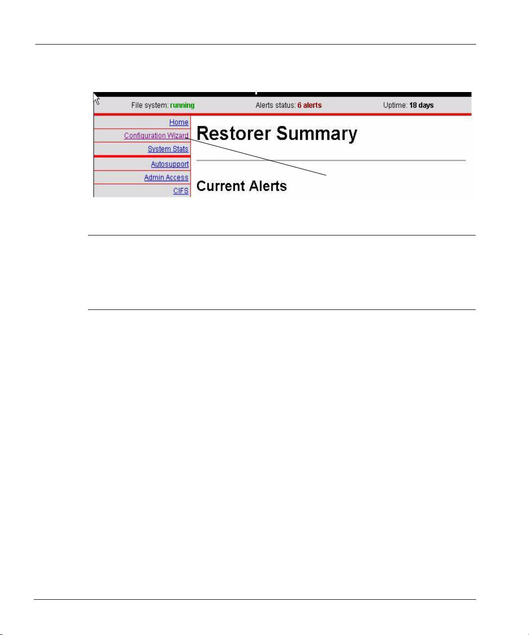
Login and Configuration
4. Click on the Configuration Wizard link as shown in Figure 15.
Configuration link
Figure 15: Configuration Wizard link
Note Most of the installation procedure in this chapter uses the command line interface as an
example. However, the Configuration Wizard of the DDR Manager has the same
configuration groups and sets the same configuration parameters. With the console, click on
links and fill in boxes that correspond to the command line examples that follow. To return
to the list of configuration sections from within one of the sections, click on the Wizard List
link in the top left corner of the Configuration Wizard screen.
If you earlier set up DHCP for one or more restorer Ethernet interfaces, a number of the config
setup
prompts display the values given to the restorer from a DHCP server. DHCP servers
normally supply values for a number of networking parameters. Press Return during the installation
to accept DHCP values. If you do not use DHCP for an interface, determine what you will use for
the following values before starting the configuration:
• Interface IP addresses.
• Interface netmasks.
• Routing gateway.
• DNS server list (if using DNS).
• A site domain name, such as yourcompany.com.
• A fully-qualified hostname for the restorer, such as rstr01.yourcompany.com.
You can configure different network interfaces on a restorer to different subnets. However,
multiple interfaces must not be linked to the same LAN or VLAN in the network.
When configuring restorer software:
• At any prompt, enter a question mark (?) for detailed information about the prompt.
• Press Return to accept a displayed value.
30 DD400 Series Restorer User Guide

Login and Configuration
• Enter either hostnames or IP addresses where ever a prompt mentions a host. Hostnames must
be fully qualified, such as srvr22.yourcompany.com.
• For any entry that accepts a list, the entries in the list can be comma-separated, space-
separated, or both.
• When configuration is complete, the system is ready to accept backup data. For NFS clients,
the restorer is set up to export the
For CIFS clients, the restorer has shares set up for
/backup and /ddvar directories using NFSv3 over TCP.
/backup and /ddvar.
The configuration utility has five sections: Licenses, Network, NFS, CIFS, and System. You can
configure or skip over any section. The command line interface automatically moves from one
section to the next. With the DDR Manager, click on the sections as shown in
Figure 16.
Configuration
sections (wizards)
Figure 16: Configuration sections
Chapter 3: Installation 31

Login and Configuration
1. The first login to the restorer can be from a serial console, keyboard and monitor, through an
Ethernet connection, or through a web browser. Log in as user sysadmin. The default password
is the serial number from the rear panel of the restorer. See
Figure 17 for the location.
Serial number
Figure 17: Serial number location
- From a serial console or keyboard and monitor, log in to the restorer at the login prompt.
- From a remote machine over an Ethernet connection, give the following command (with
the hostname you chose for the restorer) and then give the default password.
# ssh -l sysadmin host-name
sysadmin@host-name’s password:
- From a web browser, enter a path to the restorer. For example: http://rstr01/ for a
restorer named rstr01 on a local network.
2. When using the command line interface, the first prompt after login gives the opportunity to
change the sysadmin password. The prompt appears only once, at the first login to a new
system. You can change the sysadmin password immediately at the prompt or later with the
user change password command.
To improve security, Data Domain recommends that you change the
'sysadmin' password before continuing with the system
configuration.
Change the 'sysadmin' password at this time? (yes|no) [yes]:
3. When using the command line interface, the restorer command config setup starts next.
4. The first configuration section is for licensing. Licenses that you ordered with the restorer are
already installed. At the first prompt, enter yes to configure or view licenses.
- Enter the license characters, including dashes, for each license category.
- Make no entry and press Enter for categories that you have not licensed.
LICENSES Configuration
Configure LICENSES at this time (yes|no) [no]: yes
32 DD400 Series Restorer User Guide

Login and Configuration
CAPACITY License Code
Enter your CAPACITY license code []:
REPLICATION License Code
Enter your REPLICATION license code []:
- A listing of your choices appears. The NFS and CIFS features appear as licenses, but are
now part of the base software. You can accept the settings (Save), reject the settings and
leave the setup process (Abort), or return to the beginning of the current section and
change settings (Retry). A Retry shows your previous choice for each prompt. Press
Return to accept the displayed value or enter a new value.
Pending License Settings.
NFS License: ABCD-ABCD-ABCD-ABCD
CIFS License: ABCD-ABCD-ABCD-ABCD
CAPACITY License: ABCD-ABCD-ABCD-ABCD
REPLICATION License: ABCD-ABCD-ABCD-ABCD
Do you want to save these settings (Save|Abort|Retry):
5. The second section is for network configuration. At the first prompt, enter yes to configure
network parameters.
Note After configuring the restorer to use DNS, the restorer must be rebooted. Also, if DHCP is
disabled for all interfaces and then later enabled for one or more interfaces, the restorer must
be rebooted.
NETWORK Configuration
Configure NETWORK parameters at this time (yes|no) [no]:
a. The first prompt is for a restorer machine name. Enter a fully-qualified name that includes
the domain name. For example: rstr01.yourcompany.com.
Hostname
Enter the hostname for this system (fully-qualified
domain name)[]:
b. Supply a domain name, such as yourcompany.com, for use by restorer utilities, or accept
the display of the domain name used in the hostname.
Domainname
Enter your DNS domainname []:
c. Configure each Ethernet interface that has an active Ethernet connection. If you earlier set
up DHCP for an interface, the IP address and netmask prompts do not appear. You can
accept or not accept DHCP for each interface.
Chapter 3: Installation 33

Login and Configuration
- If you enter yes for DHCP and DHCP is not yet available to the interface, the restorer
attempts to set up the interface with DHCP until DHCP is available. Use the
show settings
command to display which interfaces are configured for DHCP.
net
- If you are on an Ethernet interface and you choose to not use DHCP for the interface,
the connection is lost when you complete the configuration.
- At the last prompt, entering an a (Abort) exits the configuration utility.
- Each interface is a Gigabit Ethernet connection. The same set of prompts appears for
each interface.
Ethernet port eth0:
Enable Ethernet port (yes|no) [ ]:
Use DHCP on Ethernet port eth0 (yes|no) [ ]:
Enter the IP address for eth0 [ ]:
Enter the netmask for eth0 [ ]:
- When not using DHCP on any Ethernet port, you must specify an IP address for a
default routing gateway.
Default Gateway
Enter the default gateway IP address[]:
- When not using DHCP on any Ethernet port, you can enter up to three DNS servers
for a restorer to use for resolving hostnames into IP addresses. Use a commaseparated or space-separated list. Enter a space for no DNS servers. With no DNS
servers, you can use the
net hosts commands to inform the restorer of IP
addresses for relevant hostnames.
DNS Servers
Enter the DNS Server list (zero, one, two or three IP
addresses)[]:
d. A listing of your choices appears. You can accept the settings (Save), reject the settings
and leave the setup process (Abort), or return to the beginning of the current section and
change settings (Retry). A Retry shows your previous choice for each prompt. Press
Return to accept the displayed value or enter a new value.
Pending Network Settings.
--------------- ----------------------Hostname: srvr26.yourcompany.com
Domainname: yourcompany.com
Default Gateway
DNS Server List DNS Server List
--------------- ----Cable Port Enabled DHCP IP Address Netmask
----- ---- ------- ---- --------------- --------------
eth0 yes yes (dhcp-supplied) (dhcp-supplied)
34 DD400 Series Restorer User Guide

Login and Configuration
eth1 yes yes (dhcp-supplied) (dhcp-supplied)
eth2 no n/a n/a n/a
*** eth3 yes yes (dhcp-supplied) (dhcp-supplied)
----- ---- ------- ---- --------------- -------------*** No connection on indicated Ethernet port
Do you want to save these settings (Save|Abort|Retry):
Note An information box also appears in the recap if any interface is set up to use DHCP, but does
not have a live Ethernet connection. After troubleshooting and completing the Ethernet
connection, wait for up to two minutes for the restorer to update the interface. The
column of the
net show hardware command displays whether or not the Ethernet
Cable
connection is live for each interface.
6. The third section is for CIFS (Common Internet File System) configuration and appears only if
the restorer has a CIFS license. At the first prompt, enter yes to configure CIFS parameters.
The default authentication mode is Active Directory.
Note When configuring a replica restorer as part of a Replicator pair, configure the authentication
mode, WINS server (if needed) and other entries as with the originator in the pair. The
exceptions are that a replica does not need a backup user and will probably have a different
backup server list (all machines that can access data that is on the replica).
CIFS Configuration
Configure CIFS at this time (yes|no) [no]: yes
a. Select a user-authentication method for the CIFS user accounts that connect to the
/backup and /ddvar shares on the restorer.
CIFS Authentication
Which authentication method will this system use
(Workgroup|Domain|Active-Directory) [Active Direcctory]:
The Workgroup method has the following prompts. Enter a workgroup, the name of a
CIFS backup account and password, a WINS server name, and backup server names.
Workgroup Name
Enter the workgroup name for this system
[ ]:
Do you want to add a backup user yes|no) [no]:
Backup User
Enter backup user name:
Backup User Password
Enter backup user password:
Chapter 3: Installation 35

Login and Configuration
Enter the WINS server for the restorer to use:
WINS Server
Enter the IP address for the WINS server for this system
[]:
Enter one or more backup servers as restorer clients.
Backup Servers
Enter the Backup Server list (CIFS clients of /backup)
[]:
The Domain method brings the following prompts. Enter a domain name, the name of a
CIFS backup account and optionally, one or more domain controller IP addresses, a WINS
server name, and backup server names. Press Enter with no entry to break out of the
prompts for domain controllers.
Domain Name
Enter the name of the Windows domain for this system
[ ]:
Do you want to add a backup user? (yes|no) [no]:
Backup user
Enter backup user name:
Domain Controller
Enter the IP address of domain controller 1 for this
system
[ ]:
Enter the WINS server for the restorer to use:
WINS Server
Enter the IP address for the WINS server for this system
[]:
Enter one or more backup servers as restorer clients.
Backup Servers
Enter the Backup Server list (CIFS clients of /backup)
[]:
The Active-Directory method brings the following prompts. Enter a fully-qualified realm
name, the name of a CIFS backup account, a WINS server name, and backup server
names. Data Domain
specifying a domain controller, be sure to specify a WINS server. The
recommends not specifying a domain controller. When not
restorer must meet
all active-directory requirements, such as a clock time that is no more than five minutes
different than the domain controller.
Press Enter with no entry to break out of the prompts
for domain controllers.
36 DD400 Series Restorer User Guide

Login and Configuration
Active-Directory Realm
Enter the name of the Active-Directory Realm for this
system [ ]:
Do you want to add a backup user? (yes|no) [no]:
Backup user
Enter backup user name:
Domain Controllers
Enter list of domain controllers for this system [ ]:
Enter the WINS server for the restorer to use:
WINS Server
Enter the IP address for the WINS server for this system
[]:
Enter one or more backup servers as restorer clients. An asterisk (*) is allowed as a wild
card only when used alone to mean “all.”
Backup Server List
Enter the Backup Server list (CIFS clients of /backup)
[]:
b. A listing of your choices appears. You can accept the settings (Save), reject the settings
and leave the setup process (Abort), or return to the beginning of the current section and
change settings (Retry). A Retry shows your previous choice for each prompt. Press
Return to accept the displayed value or enter a new value.
The following example is with an authentication mode of Active-Directory.
Pending CIFS Settings
--------------------- -----------------
Auth Method Active-Directory
Domain domain1
Realm domain1.local
Backup User dsmith
Domain Controllers
WINS Server 192.168.1.10
Backup Server List *
--------------------- -----------------Do you want to save these settings (Save|Abort|Retry):
Chapter 3: Installation 37

Login and Configuration
7. The fourth section is for NFS configuration and appears only if the restorer has an NFS license.
At the first prompt, enter yes to configure NFS parameters.
NFS Configuration
Configure NFS at this time (yes|no) [no]: yes
a. Add backup servers that will access the restorer through NFS. You can enter a list that is
comma-separated, space-separated, or both. An asterisk (*) opens the list to all clients.
The default NFS options are: rw, no_root_squash, no_all_squash, and secure. You can
later use
adminaccess add and nfs add /backup to add backup servers.
Backup Servers
Enter the Backup Server list (NFS clients of /backup)[]:
b. A listing of your choices appears. You can accept the settings (Save), reject the settings
and leave the setup process (Abort), or return to the beginning of the current section and
change settings (Retry). A Retry shows your previous choice for each prompt. Press
Return to accept the displayed value or enter a new value.
Pending NFS Settings.
Backup Server List:
Do you want to save these settings (Save|Abort|Retry):
8. The fifth section is for system parameters. At the first prompt, enter yes to configure system
parameters.
SYSTEM Configuration
Configure SYSTEM Parameters at this time (yes|no) [no]:
a. Add a client host from which you will administer the restorer. The default NFS options
are: rw, no_root_squash, no_all_squash, and secure. You can later use the commands
adminaccess add and nfs add /ddvar to add other administrative hosts.
Admin host
Enter the administrative host []:
b. You can add an email address so that someone at your site receives email for system alerts
and autosupport reports. For example, jsmith@yourcompany.com. By default, the restorer
email lists include an address for the Data Domain support group. You can later use the
restorer commands
alerts and autosupport to add more addresses.
Admin email
Enter an email address for alerts and support emails[]:
38 DD400 Series Restorer User Guide

Login and Configuration
c. You can enter a location description for ease of identifying the physical machine. For
example, Bldg4-rack10. The
alerts and autosupport reports display the location.
System Location
Enter a physical location, to better identify this
system[]:
d. Enter the name of a local SMTP (mail) server for restorer emails. If the server is an
Exchange server, be sure that SMTP is enabled.
SMTP Server
Enter the hostname of a mail server to relay email
alerts[]:
e. The default time zone for each restorer is the factory time zone. For a complete list of time
zones, see
“Time Zones” on page 191.
Timezone Name
Enter your timezone name:[US/Pacific]:
f. To allow the restorer to use one or more Network Time Service (NTP) servers, you can
enter IP addresses for NTP servers. The default is to enable NTP and to use multicast.
Configure NTP
Enable Network Time Service? (yes|no)|? [yes]:
Use multicast for NTP? (yes|no|?) [no]:
Enter the NTP Server list (IP addresses) [ ]:
g. A listing of your choices appears. You can accept the settings (Save), reject the settings
and leave the setup process (Abort), or return to the beginning of the current section and
change settings (Retry). A Retry shows your previous choice for each prompt. Press
Return to accept the displayed value or enter a new value.
Pending System Settings
--------------- ----------------Admin host pls@yourcompany.com
System Location Server Room 52327
SMTP Server mail.yourcompany.com
Timezone name US/Pacific
NTP Servers 123.456.789.33
--------------- -------------------Do you want to save these settings (Save|Abort|Retry):
Chapter 3: Installation 39

Additional Configuration
Note For Tivoli Storage Manager on an AIX backup server to access a restorer, you must re-add
the backup server to the restorer after completing the original configuration setup. On the
restorer, run the following command with the server-name of the AIX backup server:
# nfs add /backup server-name insecure
h. Configure the backup servers. For the most up-to-date information about setting up
backup servers for use with a restorer, go to the Data Domain Support web site
(http://support.datadomain.com/). See the Technical Notes section.
Additional Configuration
The following are common changes to the restorer configuration that users make after the
installation. Changes to the initial configuration settings are all made through the command line
interface. Each change describes the general task and the command used to accomplish the task.
• Add email addresses to the alerts list and the autosupport list. See “Add to the Email List” on
page 74 for details.
alerts add addr1[,addr2,...]
• Give access to additional backup servers. See “NFS Management” on page 129 for details.
nfs add /backup srvr1[,srvr2,...]
• From a remote machine, add an authorized SSH public key to the restorer. See “Add an
Authorized SSH Public Key” on page 60 for details.
ssh-keygen -d
ssh -l sysadmin rstr01 “adminaccess add ssh-keys” \
< ~/.ssh/id_dsa.pub
• Add remote hosts that can use FTP or TELNET on the restorer. See “Add a Host” on page 59
for details.
adminaccess add {ftp | telnet}{all | host1[,host2,...]}
• Enable HTTP, HTTPS, FTP or TELNET. The SSH, HTTP, and HTTPS services are enabled
by default. See
“Enable a Protocol” on page 60 for details.
adminaccess enable {http | https | ftp | telnet | ssh | all}
• Add a standard user. See “User Administration” on page 65 for details.
user add username
• Change a user password. See “User Administration” on page 65 for details.
user change password username
40 DD400 Series Restorer User Guide

Administering a Restorer
Administering a Restorer
To administer a restorer, use either the command line interface or the DDR Manager graphical user
interface.
Command Line Interface
The command line interface gives complete access to a restorer for the initial system configuration,
for making changes to individual system settings, and to display of system states and the state of
system operations. The remaining chapters in this book detail the use of all restorer commands and
operations. The headings in each chapter are a task-oriented list of operations performed by the
featured commands. To find the command for any task that you want to perform, do either of the
following:
• Look in the table of contents at the beginning of this guide for the heading that describes the
task.
• List the restorer commands and operations. To see a list of commands, log in to the restorer
using SSH (or TELNET if that is enabled) and enter a question mark (?) at the prompt. To see
a list of operations available for a particular command, enter the command name. To display a
detailed help page for a command, use the
command. Use the up and down arrow keys to move through a displayed command. Use the
key to exit. Enter a slash character (/) and a pattern to search for and highlight lines of
particular interest.
help command with the name of the target
q
DDR Manager
The web-based graphical user interface, the DDR Manager, is available through Ethernet
connections to a restorer. With the DDR Manager, you can do the initial system configuration,
make some configuration updates after initial configuration, and display system states and the state
of system operations. From the left panel of the DDR Manager, select the Configuration Wizard to
change configuration values or select an area such as File System to display system information.
See
Figure 18 on page 42.
Chapter 3: Installation 41

Administering a Restorer
Selections
on the
left panel
Figure 18: DDR Manager selections
42 DD400 Series Restorer User Guide

DD400g Gateway
The DD400g Gateway restorer stores data in and restores data from externally mounted disk arrays
through fiber channel connections. Currently, the DD400g supports data storage on the following
external disk arrays:
• EMC Clariion CX300/500/700
• NexSAN ATAbeast
A DD400g system has the same chassis and CPUs (two 3.2 GHz CPUs) as a DD460 restorer, but
no disks. Other points to be aware of with a DD400g are:
• Supports a single volume with a single data collection. A data collection is all the files stored
in a single restorer.
• Each LUN (or metaLUN, which is seen as a single LUN) assigned to a restorer must contain
less than 2 TB of data.
• The total amount of storage in a volume can be no more than 4.2 TB.
• The only supported network topology is a private2 GB Fiber-Channel Arbitrated Loop
(FC-AL). SAN features such as zoning and SAN-only data centers are not supported.
• Replication between two DD400g restorers must be between disk arrays that are of the same
type and size.
• With replication between a DD400g restorer and other model Data Domain restorers, the total
amount of storage on the originator must not exceed the total amount of storage on the replica.
4
• Power supplies are the only hardware in a DD400g that a customer would replace.
• A restorer does not support temporary fiber channel disconnection while the restorer is active.
Unplugging the fiber channel cable that connects the restorer and the storage array can lead to
unrecoverable errors at any time that the restorer has I/O activity. Data Domain recommends
shutting down the restorer before removing the cable.
• A restorer does not support fiber channel multipathing (also known as failover) Be sure that the
storage array is not configured as if multipathing is enabled.
• The maximum data size for a LUN that a DD400g can access is 2 TB.
• The minimum data size for a LUN that a DD400g can access is 400 GB.
43

Command Changes
• The maximum total size of all LUNs accessed by a DD400g is 4.2 TB.
• After configuring a DD400g, you cannot grow a LUN or the volume accessed by the DD400g.
• A DD400g writes to all LUNs that are on a disk array and that are available to the DD400g
(not masked).
• A Fiber Channel host bus adapter card (QLogic 2 gigabit class) in the restorer communicates
with the external disk array. See
Figure 19 for a schematic of the peripheral cards in a
DD400g.
Back panel
Restorer
front panel
Figure 19: Peripheral card slots
Command Changes
The following disk commands are not valid for a restorer using external storage. All other
commands in the Data Domain command set are available.
disk beacon
disk fail
disk unfail
disk show debug
disk show failure-history
disk show reliability-data
44 DD400 Series Restorer User Guide

Command Changes
The following disk commands report activity and information only at the LUN level, not for
individual disks in a LUN. Each
disk entry represents a LUN in output from the following
commands.
• disk show raid-info The following example shows two LUNs available to the restorer.
After the drives are “in use” line, the remainder of the drives lines are not valid.
system12# disk show raid-info
Disk State Additional Status
----- ------------ ----------------disk1 in use (dg0)
disk2 in use (dg0)
----- ------------ ----------------2 drives are "in use"
0 drives have "failed"
0 drives are "hot spare(s)"
0 drives are undergoing "reconstruction"
0 drives are undergoing "resynch"
0 drives are "not in use"
0 drives are "missing/absent"
• disk show performance Displays information similar to the following for each LUN.
system12# disk show performance
Disk Read Write Cumul. Busy
sects/s sects/s MBytes/s
----- ------- ------- -------- ---disk1 46 109 0.075 14 %
disk2 0 0 0.000 0 %
----- ------- ------- -------- ---Cumulative 0.075 MB/s, 7 % busy
• disk show detailed-raid-info Displays information similar to the following for
each LUN:
system12# disk show detailed-raid-info
Disk Group (dg0) - Status: normal
Raid Group (ext3):(raid-0)(61.01 GB) - Status: normal
Raid Group (ext3_1):(raid-100)(68.64 GB) - Status:
normal
Slot Disk State Additional Status
---- ----- ------------ ----------------1 disk1 in use (dg0)
---- ----- ------------ -----------------
Raid Group (ppart):(raid-0)(3.04 TB) - Status: normal
Chapter 4: DD400g Gateway 45

Command Changes
Raid Group (ppart_1):(raid-100)(3.04 TB) - Status:
normal
Slot Disk State Additional Status
---- ----- ------------ ----------------1 disk1 in use (dg0)
2 disk2 in use (dg0)
---- ----- ------------ -----------------
Spare Disks
None
Unused Disks
None
• disk show config Displays information similar to the following for each LUN.
- LUN is the LUN number used by the external storage system.
- Port WWN is the world-wide number of the port on the external storage system through
which data is sent to the restorer.
- Manufacturer/Model includes a label that identifies the manufacturer. The display may
include a model ID or RAID type or other information depending on the vendor string sent
by the external storage system.
- Firmware is the firmware level used by the external storage controller.
- Serial No. is the serial number of the external storage system.
- Capacity is the amount of data in a volume sent to the restorer.
system12# disk show config
Disk LUN Port WWN Manufacturer/Model
----- --- ----------------------- ------------------
disk1 0 50:06:01:60:30:20:e2:12 DGC RAID 3
disk2 4 50:06:01:60:30:20:e2:12 DGC RAID 3
----- --- ----------------------- ------------------
Firmware Serial No. Capacity
-------- -------------- --------
0216 APM00045001866 1.56 TB
0216 APM00045001866 1.56 TB
-------- -------------- --------
2 drives present.
46 DD400 Series Restorer User Guide

Installation
• disk show summary Displays information similar to the following. After drives are “in
use”, the remainder of the drives lines are not valid.
system12# disk show summary
Configuration: 2 drives present.
RAID: 2 drives are "in use"
RAID: 0 drives have "failed"
RAID: 0 drives are "hot spare(s)"
RAID: 0 drives are undergoing "reconstruction"
RAID: 0 drives are undergoing "resynch"
RAID: 0 drives are "not in use"
RAID: 0 drives are "missing/absent"
Performance: Cumulative 0.075 MB/s, 7 % busy
Installation
A restorer using external storage must first connect with the external storage and then configure the
use of the storage.
1. For hardware setup (setting up the restorer chassis), see “Hardware Installation” on page 25.
2. On the external disk array system, create the LUNs for use by the restorer.
3. On the external disk array system, configure LUN masking so that the restorer can see only
those LUNs that should be available to the restorer. The restorer writes to every LUN that is
available.
4. Connect the Fiber Channel cable from the Fiber-Channel Arbitrated Loop (FC-AL) to the
Fiber Channel HBA card ports on the back of the restorer. The cable and the external storage
must also be connected to the FC-AL.
5. Press the Power button on the front of the restorer. During the initial system start, the restorer
does not know of the available LUNs. The following menu appears with the Do a New Install
entry selected:
New Install
1. Do a New Install
2. Show Configuration
3. Reboot
Chapter 4: DD400g Gateway 47

Installation
6. Check that the LUNs available from the connected array system are correct. Use the
down-arrow key, select Show Configuration, and press Enter. The configuration menu appears
with Show Storage Information selected:
System Configuration
(Before Installation)
1. Show Storage Information
2. Show Head Information
3. Go to Previous Menu
4. Go to Rescue Menu
5. Reboot
7. Press Enter to display storage information. Each LUN that is available from the array system
appears as a one line entry in the List of SCSI Disks/LUNs. The Valid RAID DiskGroup UUID
List section shows no disk groups until after installation. Use the arrow keys to move up and
down in the display.
Storage Details
Software Version: 3.1.0.0-19112
Valid RAID DiskGroup UUID List:
ID DiskGroup UUID Last Attached Serialno
------------------------------------------------
-- No diskgroup uuids were found --
List of SCSI Disks/LUNs:
(Press ctrl+m for disk size information)
ID UUID tgt lun loop wwpn comments
---------------------------------------------------------------
1 No UUID 0 0 0 500601603020e212
2 No UUID 0 4 0 500601603020e212
Number of Flash disks: 1
----------------------------------------
Errors Encountered:
----------------------------------------
-- No errors to report
8. Press Enter to return to the New Install menu.
9. Use the up-arrow key to select Do a New Install.
10. Press Enter to start the installation. The system automatically configures the use of all LUNs
available from the array.
48 DD400 Series Restorer User Guide

Troubleshooting
11. Press Enter to accept the Yes selection in the New Install? Are you sure? display. No other user
input is required.
A number of displays appear during the reboot. Each one automatically times-out with the
displayed information and the reboot continues.
12. When the reboot completes, the login prompt appears. Login and configure the restorer as
explained in the Installation chapter of this manual beginning with
step 2 on page 32.
Troubleshooting
Problems during installation or loss of access to a configured LUN causes the following menu to
appear. Use the arrow keys to navigate the menu and press Enter to display the next level of
information.
System Misconfigured
(The system has 0 disks/LUNs!)
1. Show Storage Information
2. Show Head Information
3. Show Head Swap Menu
4. Show New Install Menu
5. Go to Rescue Menu
6. Reboot
• Show Storage Information displays the LUNs that are currently available to the restorer. If the
Comments column of the List of SCSI Disks/LUNs section includes an Incomplete, one or more
LUNs configured for the restorer is not available.
• Show Head Information displays informative error messages in the Errors Encountered
section. For example, the version number of the software on the restorer is also stored in a file
on the external storage. If the version number on the restorer does not match the version
number stored on external storage, an error message appears.
Head Details
Software Version: 3.1.0.0-18087
Model Type: DD400G
Serial Number xxxx
Has Flash: YES
Previously Saved RAID DiskGroup UUID List:
ID DiskGroup UUID
--------------------------------------------1 1302c2433dec8025
---------------------------------------------
Chapter 4: DD400g Gateway 49

Troubleshooting
Errors Encountered:
---------------------------------------------
--Version numbers do not match
• Go to Rescue Menu allows you to display the system log.
Rescue Options
1. View Log
2. Go to Bash
3. Go to Previous Menu
4. Reboot
50 DD400 Series Restorer User Guide

Configuration Management
The restorer config command allows you to examine and modify all of the configuration
parameters that are set in the initial system configuration. See
complete command syntax. The license command allows you to add, delete, and display feature
licenses. See
The Config Command
The config setup command brings up the same prompts as the initial system configuration.
You can change any of the configuration parameters as detailed in the section
Configuration” on page 29. All of the config operations are available only to administrative
users.
You can also use other restorer commands to change individual configuration settings. Most of the
remaining chapters of this manual detail using individual commands. An example of an individual
command that sets only one of the
Change Configuration Settings
To change multiple configuration settings with one command, use the config setup operation.
The operation displays the current value for each setting. Press the Return key to retain the current
value for a setting. Administrative users only.
“license” on page 222 for the complete command syntax.
config possibilities is nfs add to add NFS clients.
5
“config” on page 210 for the
“Login and
config setup
See “Login and Configuration” on page 29 for details about using config setup. Enter the
command from a command prompt to change values after the initial setup.
Many other restorer commands change configuration settings. For example, the user command
adds another user account each time a user is added.
Note You can also use the DDR Manager graphical user interface to change all of the same
parameters that are available through the
select Configuration Wizard in the top section of the left panel.
51
config setup command. In the DDR Manager,

The Config Command
Save and Return a Configuration
Using SSH, you can direct output from the restorer config dump command, which returns all
restorer configuration settings, into a file on a remote host from which you do restorer
administration. You can later use SSH to return the file to the restorer, which immediately
recognizes the settings as a configuration and accepts the settings as the current configuration.
For example, the following command connects with the restorer dd10 as user sysadmin, asks for the
password, returns output from the command
the output in the local file (remote from the
# ssh -l sysadmin dd10 config dump > /tmp/config12
sysadmin@dd10’s password:
reg set config.aliases.default_set.root = '1'
reg set config.aliases.default_set.sysadmin = '1'
reg set config.aliases.sysadmin.df = 'filesys show space'
reg set config.aliases.sysadmin.halt = 'system poweroff'
.
.
.
The following command returns the configuration settings from the file /tmp/config12 to the
restorer. The settings immediately become the current configuration for the restorer.
config dump that is run on the restorer, and stores
restorer) /tmp/config12:
# ssh -l sysadmin dd10 < /tmp/config12
sysadmin@dd10’s password:
Reloading configuration: (CHECKED)
Security access lists (from adminaccess) updated
Bringing up DHCP client daemon for eth0...
Bringing up DHCP client daemon for eth2...
Reset the Location Description
To reset the location description to the system default of a null entry, use the config reset
location
command. Administrative users only.
config reset location
Reset the Mail Server to a Null Entry
To reset the mail server used by the restorer to the system default of a null entry, use the config
reset mailserver
config reset mailserver
command. Administrative users only.
52 DD400 Series Restorer User Guide

The Config Command
Reset the Time Zone to the Default
To reset the time zone used by the restorer to the system default of US/Pacific, use the config
reset timezone
config reset timezone
command. Administrative users only.
Set an Administrative Email Address
To give an address to which the restorer sends alerts and autosupport messages, use the config
set admin-email
autosupport and alerts commands to add other email addresses. Administrative users only.
config set admin-email email-address
For example:
# config set admin-email jsmith@company.com
The Admin email is: jsmith@company.com
To check the operation, use the config show admin-email command.
command. The system needs only one administrative email address. Use the
Set an Administrative Host Name
To change the machine from which you can log into the restorer to see system logs and use system
commands, use the
simple host name, a host name with a fully-qualified domain name, or an IP address.
Administrative users only.
config set admin-host host
For example, to set the administrative host to admin12.yourcompany.com:
# config set admin-host admin12.yourcompany.com
To check the operation, use the config show admin-host command.
config set admin-host host operation. The host name can be a
Change the System Location Description
To change the description of a restorer location, use the config set location
“location”
viewing alerts and autosupport emails. If the description contains one or more spaces, the
description must be in double quotes. Administrative users only.
config set location ”location”
Chapter 5: Configuration Management 53
operation. A description of a physical location helps identify the machine when

The Config Command
For example, to set the location description to row2-num4-room221:
# config set location “row2-num4-room221”
To check the operation, use the config show location command.
Change the Mail Server Hostname
To change the SMTP mail server used by the restorer, use the config set mailserver
host
operation. Administrative users only.
config set mailserver host
For example, to set the mail server to mail.yourcompany.com:
# config set mailserver mail.yourcompany.com
To check the operation, use the config show mailserver command.
Set a Time Zone for the System Clock
To set the system clock to a specific time zone, use the config set timezone operation. The
default setting is US/Pacific. See the appendix:
time zones. For the change to take effect for all currently running processes, you must reboot the
restorer. The operation is available to administrative users only.
“Time Zones” on page 191 for a complete list of
config set timezone zone
For example, to set the system clock to the time zone that includes Los Angeles, California, USA:
# config set timezone Los_Angeles
To display time zones, enter a category or a partial zone name. The categories are: Africa, America,
Asia, Atlantic, Australia, Brazil, Canada, Chile, Europe, Indian, Mexico, Mideast, Pacific, and US.
The following examples show the use of a category and the use of a partial zone name:
# config set timezone us
US/Alaska US/Aleutian US/Arizona US/Central
US/Eastern US/East-Indiana US/Hawaii US/Indiana-Starke
US/Michigan US/Mountain US/Pacific US/Samoa
# config set timezone new
Ambiguous timezone name, matching ...
America/New_York Canada/Newfoundland
54 DD400 Series Restorer User Guide

The Config Command
Display the Administrative Email Address
To display the administrative email address that the restorer uses for email from the alerts and
autosupport utilities, use the
config show admin-email
The display is similar to the following:
# config show admin-email
The Admin Email is: rjones@yourcompany.com
config show admin-email operation.
Display the Administrative Host Name
To display the administrative host from which you can log into the restorer to see system logs and
use system commands, use the
config show admin-host
The display is similar to the following:
# config show admin-host
The Admin Host is: admin12.yourcompany.com
config show admin-host operation.
Display the System Location Description
To display the restorer location description, if you gave one, use the config show location
operation. Administrative users only.
config show location
The display is similar to the following:
# config show location
The System Location is: bldg12 rm 120 rack8
Display the Mail Server Hostname
To display the name of the mail server that the restorer uses to send email, use the config show
mailserver
config show mailserver
The display is similar to the following:
# config show mailserver
The Mail (SMTP) server is: mail.yourcompany.com
Chapter 5: Configuration Management 55
operation.

The License Command
Display the Time Zone for the System Clock
To display the time zone used by the system clock, use the config show timezone operation.
config show timezone
The display is similar to the following:
# config show timezone
The Timezone name is: US/Pacific
The License Command
The license command manages licensed features on a restorer.
Add a License
To add a feature license, use the license add operation. The code for each license is a string of
16 letters with dashes. Include the dashes when entering the license code. Administrative users
only.
The licensed features are:
• CAPACITY-FULLSIZE
Use all the disk space on a restorer. When upgrading from HALF to FULL, simply add the
FULL license. The HALF license is automatically replaced and the increased disk space is
immediately available.
• CAPACITY-HALFSIZE
Use only half the disk space on a restorer.
• REPLICATION
Use the Data Domain Replicator for replication of data from one restorer to another.
license add license-code
For example:
# license add ABCD-BCDA-CDAB-DABC
License “ABCE-BCDA-CDAB-DABC” added.
Remove All Feature Licenses
To remove all licenses use the license reset operation. The system then behave as though it
has the single default license of
license reset
56 DD400 Series Restorer User Guide
CAPACITY-HALFSIZE. Administrative users only.

The License Command
Remove a License
To remove a current license, use the license del operation. Enter the license feature name or
code (as shown with the
license del {license-feature | license-code}
For example:
# license del replication
The REPLICATION license is removed.
license show command). Administrative users only.
Display Licenses
The license display shows only those features licensed on the restorer. Administrative users only.
## is the license number of the feature.
License Key is the characters of a valid license key.
Feature is the name of the licensed feature. Current licensed features are disk space for data of full
or half and the Replicator for replication from one restorer to another. NFS and CIFS are default
features included with no license fee.
Display
To display current licenses and default features, use the license show operation. Each line
shows the license code.
license show
For example:
# license show
## License Key Feature
-- ------------------- ----------------1 ABCD-BCDA-CDAB-DABC NFS
2 BCDE-CDEB-DEBC-EBCD CIFS
3 CDEF-DEFC-EFCD-FCDE CAPACITY-FULLSIZE
4 DEFA-EFCD-FCDE-CDEF REPLICATION
-- ------------------ ----------------
Chapter 5: Configuration Management 57

The License Command
58 DD400 Series Restorer User Guide

Access Control for Administration
The restorer adminaccess command allows remote hosts to use the FTP, TELNET, and SSH
administrative protocols on the restorer. The command is available only to restorer administrative
users. See
The FTP and TELNET protocols have host-machine access lists that limit access. The SSH
protocol is open to the default user sysadmin and to all restorer users added with the
command. By default, only the SSH protocol is enabled.
Add a Host
To add a host (IP address or hostname) to the FTP or TELNET protocol access lists, use the
adminaccess add operation. For the FTP list, use an IP address for each host or a class-C
network address that includes the hosts. You can enter a list that is comma-separated,
space-separated, or both. To give access to all hosts, the host-list can be an asterisk (*).
Administrative users only.
For example, to add srvr24 and srvr25 to the list of hosts that can use TELNET on the restorer:
To allow an entire local subnet to use TELNET on the restorer:
“adminaccess” on page 197 for the complete command syntax.
adminaccess add {ftp | telnet} host-list
# adminaccess add telnet srvr24,srvr25
6
user add
# adminaccess add telnet 192.123.45.
Remove a Host
To remove hosts (IP addresses, hostnames, or asterisk (*)) from the FTP or TELNET access lists,
use the
adminaccess del operation. You can enter a list that is comma-separated,
space-separated, or both. Administrative users only.
adminaccess del {ftp | telnet} host-list
For example, to remove srvr24 from the list of hosts that can use TELNET on the restorer:
# adminaccess del telnet srvr24
59

Enable a Protocol
Enable a Protocol
By default, the SSH, HTTP, and HTTPS services are enabled. FTP and TELNET are disabled.
HTTP and HTTPS allow users to log in through the web-based graphical user interface. The
adminaccess enable operation enables a protocol on the restorer. Note that to use FTP and
TELNET, you must also add host machines to the access lists. Administrative users only.
adminaccess enable {http | https | ftp | telnet | ssh | all}
For example, to enable the FTP service:
# adminaccess enable ftp
Disable a Protocol
To disable a service on the restorer, use the adminaccess disable operation. Disabling FTP
or TELNET does not affect entries in the access lists. If all services are disabled, the restorer is
accessible only through a serial console or keyboard and monitor. Administrative users only.
adminaccess disable {http | https | ftp | telnet | ssh | all}
For example, to disable the FTP service:
# adminaccess disable ftp
Reset System Access
By default, FTP and TELNET are disabled and have no entries in their access lists. SSH is enabled.
No one is able to use FTP or TELNET unless the appropriate access list has one or more host
entries. The
default state of disabled with no entries and sets SSH to enabled. Administrative users only.
adminaccess reset {ftp | telnet | ssh | all}
For example, to reset the FTP list to an empty list and reset FTP to disabled:
# adminaccess reset ftp
adminaccess reset operation returns the FTP and TELNET protocols to the
Add an Authorized SSH Public Key
Adding an authorized SSH public key to the SSH key file on a restorer is done from a machine that
will access the restorer. Adding a key allows a user to log in from the remote machine to the
restorer without entering a password. After creating a key on the remote machine, use the
adminaccess add ssh-keys operation. Administrative users only.
adminaccess add ssh-keys
60 DD400 Series Restorer User Guide

Remove an SSH Key File Entry
For example, the following steps create a key and then write the key to a restorer:
1. On the remote machine, create the public and private SSH keys.
jsmith > ssh-keygen -d
Generating public/private dsa key pair.
Enter file in which to save the key (/home/jsmith/.ssh/id_dsa):
.
.
2. Press Enter to accept the file location and other defaults. The public key created under
/home/jsmith/.ssh (in this example) is id_dsa.pub.
3. On the remote machine, write the public key to the restorer, dd10 in this example. The restorer
asks for the sysadmin password before accepting the key:
jsmith > ssh -l sysadmin dd10 “adminaccess add ssh-keys” \
< ~/.ssh/id_dsa.pub
Remove an SSH Key File Entry
To remove one entry from the SSH key file, use the adminaccess del ssh_keys lineno
operation. The
ssh-keys
lineno variable is the line number as displayed by the adminaccess show
command. Available only to administrative users.
adminaccess del ssh-keys lineno
For example, to remove the third entry in the SSH key file:
# adminaccess del ssh-keys 3
Remove the SSH Key File
To remove the entire SSH key file, use the adminaccess reset ssh-keys operation.
Available only to administrative users.
adminaccess reset ssh-keys
Create a New HTTPS Certificate
To generate a new HTTPS certificate for the restorer, use the adminaccess https
generate certificate
adminaccess https generate certificate
Chapter 6: Access Control for Administration 61
command. Available only to administrative users.

Display the SSH Key File
Display the SSH Key File
To display all entries in the SSH key file, use the adminaccess show ssh-keys operation.
The output gives a line number to each entry. Available only to administrative users.
adminaccess show ssh-keys
Display Hosts and Status
The display shows every access service available on a restorer, whether or not the service is
enabled, and a list of hostnames that are allowed access through each service that uses a list. An
N/A in the Allowed Hosts column means that the service does not use a list. A - (dash) means that
the service can have a list, but currently has no hosts in the list. Administrative users only.
Display
To display protocol access lists and status, use the adminaccess show operation or click
Admin Access in the left panel of the DDR Manager.
adminaccess show
For example, to show the status and lists for all services:
# adminaccess show
Service Enabled Allowed Hosts
-------- -------- -----------------------ssh yes N/A
telnet no -
ftp yes admin10.yourcompany.com
admin22.yourcompany.com
http yes N/A
https no N/A
-------- -------- ------------------------
Return Command Output to a Remote machine
Using SSH, you can have output from restorer commands return to a remote machine at login and
then automatically log out. Available only to the user sysadmin. For example, the following
command connects with the machine dd10 as user sysadmin, asks for the password, and returns
output from the command
# ssh -l sysadmin dd10 filesys status
sysadmin@dd10’s password:
The filesystem is enabled
62 DD400 Series Restorer User Guide
filesys status.
 Loading...